Embed Size (px)
Citation preview

_______________________
Cable Burial Risk Assessment Methodology Guidance for the Preparation of Cable Burial Depth of Lowering Specification CTC835, February 2015
_______________________

Cable Burial Risk Assessment Methodology: Guidance for the Preparation of Cable Burial Depth of Lowering Specification
2
Table of Contents
Table of Contents 2
Foreword 4
1 Introduction 5
1.1 Background 5 1.2 Why is a CBRA method required? 6 1.3 Objectives 7 1.4 Extents/Limitations 8 1.5 Abbreviations and definitions 9
2 Relevant regulations and existing guidance 10
3 Methodology 12
4 Cable routeing 14
5 Data collation and review 15
6 Assessment of seabed conditions 17
7 Risk Register / Threat Assessment 18
7.1 Natural 18 7.1.1 Sediment Mobility 18 7.1.2 Seismic Activity 18 7.1.3 Submarine Landslide 18 7.2 Anthropogenic 19 7.2.1 Dredging/Aggregate Extraction/Subsea Mining/Dumping 19 7.2.2 Other Cables, Umbilical, Pipelines 19 7.2.3 Benthic Fishing 19 7.2.4 Shipping 20 7.2.5 Exclusions 20 7.3 Risk Mitigation 20
8 Probabilistic risk assessment process 21
8.1 Protection from Shipping 21 8.1.1 Interconnector, Export or Inter Array Cables? 21 8.2 Protection from all vessels? 23 8.3 Probabilistic Method 24 8.4 Ptraffic 25 8.5 Pwd 26 8.6 Vship and Dship 26 8.7 Pincident 28

Cable Burial Risk Assessment Methodology: Guidance for the Preparation of Cable Burial Depth of Lowering Specification
3
8.8 Exclusions and Limitations 32 8.8.1 Prevailing Metocean Conditions 32 8.8.2 Human Factor 33 8.9 Acceptable Risk 33
9 Specifying Depth of Lowering 34
9.1 Depth of Lowering Definition 34 9.2 Anchor Size 35 9.3 Anchor Penetration 37 9.4 Protection from Sediment Mobility 38 9.5 Protection from Fishing 38 9.6 Factor of Safety (FoS) 40 9.7 Consultation with Trenching Contractors 41
10 References 42
Appendix A 43
Appendix B 47
Conclusions 61
Cable Burial Risk Assessment Methodology: Guidance for the Preparation of Cable Burial Depth of Lowering Specification
4
Foreword
The Burial Protection Index has been in use for over a decade. Originally developed for fibre optic communication cables, it has been widely applied to the first and second generation offshore wind farms.
This first and second generation of wind farms have seen significant cost overruns and schedule delays. A review of the insurance claims indicates that issues with cabling have been disproportionate to their capital cost. Optimising the specified Depth of Lowering and therefore, reducing cable handling and widening the choice of tools and methods capable of trenching the cables is considered an approach that will contribute to reducing these problems.
The purpose of this document is to present a new ‘open source’ Cable Burial Risk Assessment Method which advances the BPI method. Using probabilistic analysis the new method can be used to optimise the specified depth of lowering.
The new method has been developed by a consortium of UTEC Geomarine, Cathie Associates and Xodus Ltd on behalf of the Carbon Trust Offshore Wind Accelerator (OWA). The OWA is a joint industry project involving nine developers who represent approximately three‐quarters of the UK’s licenced capacity – DONG Energy, E.ON, Mainstream Renewable Power, RWE Innogy, Scottish Power Renewables, SSE Renewables, Statkraft, Statoil and Vattenfall.
The OWA partners are of the consistent opinion that significant cost savings can be made by optimising the specified cable Depth of Lowering.
This guidance is intended to offer a standardised, repeatable and qualitative method that can be used by all stakeholders involved in the development of a wind farm.
Cable Burial Risk Assessment Methodology: Guidance for the Preparation of Cable Burial Depth of Lowering Specification
5
1 Introduction
1.1 Background
The Offshore Wind Accelerator (OWA) is a world leading industry‐led collaborative programme between the UK government, Scottish Government and industry, designed and managed by the Carbon Trust. The multi‐million pound programme has been running since 2008 with the aim of bringing down the costs of low carbon electricity produced by offshore wind farms.
The typical cost of cable supply and installation is in the order of 8‐12% of overall CAPEX costs. Information from insurance brokers and underwriters indicate that 80% of European offshore wind farm insurance claims were cable related – of these 62% related to cable damage during construction, although not all attributable to cable burial operations. In addition, to the knowledge of the OWA partners there is no evidence of anchor strikes and/or dragging of either export or inter‐array cables, during operations within offshore wind farms in UK waters. This skew of threats to cable integrity towards construction activities and away from external threats reinforced the need to reconsider how the Depth of Lowering was specified; optimising the Depth of Lowering potentially improves the economics of the installation and minimises the risk, whilst still keeping cables safely separated from other seabed users, particularly fishermen.
It is anticipated, and experience suggests, that the optimisation of the Depth of Lowering specification in terms of external threats will result in a reduction in the Depth of Lowering specification in many ground conditions and external risk scenarios. As such, it may be anticipated that a number of potential benefits arise:
Reduction in costs associated with less time and, possibly, alternative vessels and equipment required for conducting burial operations
Increase in the potential for vessel / tool selection options – most efficient and effective
Easier access for cable recovery and repairs
Reduction in cable handling during burial operations reduces potential risk of damage
In late 2013 the Cable Installation OWA Technical Working Group (TWG) contracted UTEC Geomarine, Cathie Associates and Xodus Group to complete a wide ranging study into the site investigations, trenching assessments and burial risk assessments that are completed in the design stage of wind farm projects. The study included significant consultation with trenching contractors, consultancies involved in the development of wind farms and the wind farm developers of the OWA.
The study included the following subjects:
A detailed review of site investigation and survey methods used for cable route design, including a review of alternative methods that could improve cable installation;
A detailed review of the state of the market for trenching tools and contractors available to European wind farm developers. At the time of the study 97 trenching tools operated by 20 different contractors were identified;
A review of the applicability and suitability of the BPI/Threatline method for use on subsea power cables;

Cable Burial Risk Assessment Methodology: Guidance for the Preparation of Cable Burial Depth of Lowering Specification
6
A new Cable Burial Risk Assessment Methodology (CBRA), as presented in this document; and,
A high level cost benefit analysis that can be used to review the new CBRA and different survey methods.
The OWA partners decided to publish the new CBRA Method for use by anyone involved in wind farm development; however, the remainder of the study is confidential to the OWA partners.
1.2 Why is a CBRA method required?
Completing installation of power cables in a cost effective manner is essential for future wind farm developments. One way this can be completed is by optimising the required Depth of Lowering, which may either increase the number of cable burial assets available for depth of lowering during installation or allow use of an alternative trenching method, increasing competition, expanding the supply chain and therefore reducing costs.
Nevertheless, adequate protection for the power cables is required; damage to cables can result in a potentially significant loss of revenue and increased insurance premiums. If an export cable is damaged, complete loss is possible for a significant time because power cables are difficult and costly to repair. In addition allowing other users of the seabed to have free access without danger of snagging or fouling is essential where possible. Understanding the actual threat to a cable is essential in assessing the lifetime risk to the system.
Understanding the whole life cost of the system including insurance, cable repairs or loss of revenue is essential for development decisions and critical for the sale of export cables under the UK OFTO regime, or otherwise. Array cables are not influenced by OFTO processes, but all the other factors apply.
The Burial Protection Index (BPI) concept was developed in the 1990’s to assess the protection given to submarine fibre optic cables in varying seabed conditions, and used to set optimum Depth of Lowering for adequate protection from external threats. The method was first proposed by Mole et al (1997)1 and further discussed by Allan (1999)2 it was extended to include the concept of threat lines by Jongergouw (2001)3.
The BPI method has been used on thousands of kilometres of fibre optic communications cable. It has been modified by developers and contractors to suit the needs of wind farms; however, it is recognised that it is not necessarily fit for purpose. There are a number of limitations in the method including but not limited to:
No longer widely used – Risk based approaches are being developed by individual developers and consultancies
It only covers anchors of limited sizes
It is conservative with regards to protection from fishing gear and soft clay sea beds
1 Mole, P., Featherstone, J. and Winter, S. (1997) Cable Protection – Solutions Through New Installation and Burial Approaches. SubOptic ’97. San Francisco. 2 Allan, PG. (1999), Selecting Appropriate Cable Burial Depths – A Methodology, Submarine
Communications, Cannes 3 Jongergouw, M. et al (2001), Industry developments in Burial Assessment surveying, SubOptic 2001, Kyoto
Cable Burial Risk Assessment Methodology: Guidance for the Preparation of Cable Burial Depth of Lowering Specification
7
It ignores:
- Water depth
- Probability of incidents involving anchors
- Frequency and size of vessels in transit
- Coastal erosion and changes in the seabed profile
It does not provide a means of quantifying the residual risk post installation of assessing whole life costs of the cable.
If Depth of Lowering is not achieved it provides no means to estimate the type and amount of remedial protection.
A number of these limitations are dealt with through the engineering judgement of the design team; however, this limits the standardisation of specifications and can lead to significant conservatism from perceived threats.
A number of developers, contractors and consultancies have turned to guidance from the oil and gas industry, particularly DNV (Ref 3, 4, 5). This recommended practice is well established and has been applied to a number of cable installation projects; however, due to the focus on safety and significant consequences of a damaged oil pipeline the output is very conservative, and not necessarily proportionate for wind farm power cables.
The use of probabilistic methods has become widespread to try to limit the amount of qualitative assessment that is required. This allows for repeatability of assessments by different engineers and more reliable comparisons of different mitigation approaches. An industry review as part of the Carbon Trust OWA highlighted the variations and similarities of different methods being employed. These methods all vary subtly and it was deemed appropriate to provide a unifying method that might be used by all stakeholders in wind farm development, construction and operation.
This guidance is presented as a unifying method in order to allow all stakeholders in the development, specification, installation and operation of subsea power cables to compare risks to cables, and complete cost benefit analyses for the whole life operation of cables.
1.3 Objectives
The key objective of the CBRA methodology is to have a repeatable process that defines a target Depth of Lowering which is practically and economically achievable whilst providing adequate protection.
The CBRA method can be used by any stakeholder involved in a wind farm, from development, installation, operation to decommissioning. When applied by different engineers the results should be very similar or the steps taken clearly traceable so that reasoned debate can be enabled.
It was agreed that the new method would not provide a series of lookup tables for different soil conditions, trenching tools and anticipated threats. The variation in site conditions at different wind farms and the engineering judgement for intermediate conditions would not allow the clarity required. As such the new method is not an extension of the BPI/Threatline method but a completely different approach.
Cable Burial Risk Assessment Methodology: Guidance for the Preparation of Cable Burial Depth of Lowering Specification
8
The new CBRA Method starts with the assumption that it is impractical to protect a subsea cable from all possible threats; e.g. it is not sensible to specify a Depth of Lowering to protect from a 20 tonne anchor if that threat occurs only once in every ten thousand vessel crossings.
The CBRA method produces a probability of a strike on the cable given this selected Depth of Lowering. The method should then be used iteratively to find the optimum Depth of Lowering that results in a probability of a strike which is acceptable to the developer, operator and stakeholders as appropriate.
It is anticipated that where stakeholders and consenting bodies have requested a significant Depth of Lowering on existing wind farms due to a perceived threat, the probabilistic method shown here can be used to support the safe reduction of specified depths based on actual site conditions.
The CBRA method can be used multiple times during the wind farm development. During design stages the target depth of lowering for trenching operations will be determined. After trenching operations it can be used to determine the change in risk profile and requirement for post trench mitigation if the depth of lowering is not achieved. Once the cable is in operation, by updating the survey data CBRA can be used to assess the impact of changes in the seabed profile. At the point of decommissioning it can be used to assess the viability of leaving cables in place long term.
The CBRA method, whilst designed for offshore wind farms, may be equally applicable to interconnectors or any other subsea power cable. After all an interconnector is the same as a wind farm export cable, except there is landfall at each end.
1.4 Extents/Limitations
The CBRA method does not cover:
Detailed rules on how to design an appropriate cable route; it is a tool to be used during this process to help decision making;
Protection from hazards which cannot be mitigated against using cable burial, e.g. UXO;
The requirements of regulatory bodies who might prescribe a minimum Depth of Lowering; however, it might be used as a tool to offer a justified optimisation;
The method does not specify the methods or extent of survey data that should be acquired. A number of other guidelines and specifications already exist for this;
The risk to the cable during installation is not specifically covered. By optimising the Depth of Lowering, cable handling is reduced and trenching is potentially completed faster with alternate machinery that are of a reduced threat to the cable; and,
The selection of an appropriate trenching tool is not discussed in the CBRA method. Early engagement with trenching contractors is recommended to ascertain the limitations and capabilities of different tools in the site specific conditions. This should lead to the selection of the practically and economically achievable depth that starts the analysis.
The proposed new method is not intended as the only means of cost reduction, nor is the CBRA method intended to replace good engineering judgement which is always vital.
Cable Burial Risk Assessment Methodology: Guidance for the Preparation of Cable Burial Depth of Lowering Specification
9
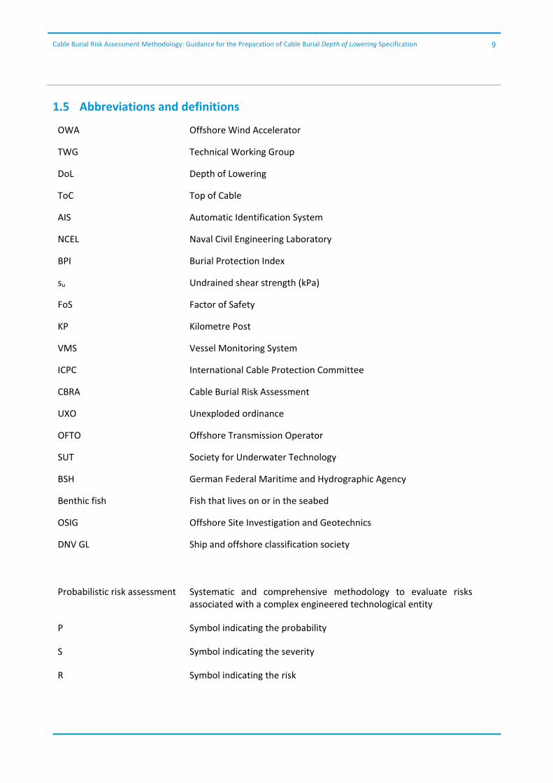
1.5 Abbreviations and definitions
OWA Offshore Wind Accelerator
TWG Technical Working Group
DoL Depth of Lowering
ToC Top of Cable
AIS Automatic Identification System
NCEL Naval Civil Engineering Laboratory
BPI Burial Protection Index
su Undrained shear strength (kPa)
FoS Factor of Safety
KP Kilometre Post
VMS Vessel Monitoring System
ICPC International Cable Protection Committee
CBRA Cable Burial Risk Assessment
UXO Unexploded ordinance
OFTO Offshore Transmission Operator
SUT Society for Underwater Technology
BSH German Federal Maritime and Hydrographic Agency
Benthic fish Fish that lives on or in the seabed
OSIG Offshore Site Investigation and Geotechnics
DNV GL Ship and offshore classification society
Probabilistic risk assessment Systematic and comprehensive methodology to evaluate risks associated with a complex engineered technological entity
P Symbol indicating the probability
S Symbol indicating the severity
R Symbol indicating the risk
Cable Burial Risk Assessment Methodology: Guidance for the Preparation of Cable Burial Depth of Lowering Specification
10
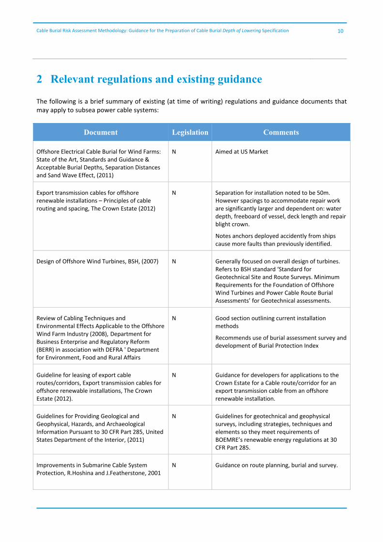
2 Relevant regulations and existing guidance
The following is a brief summary of existing (at time of writing) regulations and guidance documents that may apply to subsea power cable systems:
Document Legislation Comments
Offshore Electrical Cable Burial for Wind Farms: State of the Art, Standards and Guidance & Acceptable Burial Depths, Separation Distances and Sand Wave Effect, (2011)
N Aimed at US Market
Export transmission cables for offshore renewable installations – Principles of cable routing and spacing, The Crown Estate (2012)
N Separation for installation noted to be 50m. However spacings to accommodate repair work are significantly larger and dependent on: water depth, freeboard of vessel, deck length and repair blight crown.
Notes anchors deployed accidently from ships cause more faults than previously identified.
Design of Offshore Wind Turbines, BSH, (2007)
N Generally focused on overall design of turbines. Refers to BSH standard ‘Standard for Geotechnical Site and Route Surveys. Minimum Requirements for the Foundation of Offshore Wind Turbines and Power Cable Route Burial Assessments’ for Geotechnical assessments.
Review of Cabling Techniques and Environmental Effects Applicable to the Offshore Wind Farm Industry (2008), Department for Business Enterprise and Regulatory Reform (BERR) in association with DEFRA ' Department for Environment, Food and Rural Affairs
N Good section outlining current installation methods
Recommends use of burial assessment survey and development of Burial Protection Index
Guideline for leasing of export cable routes/corridors, Export transmission cables for offshore renewable installations, The Crown Estate (2012).
N Guidance for developers for applications to the Crown Estate for a Cable route/corridor for an export transmission cable from an offshore renewable installation.
Guidelines for Providing Geological and Geophysical, Hazards, and Archaeological Information Pursuant to 30 CFR Part 285, United States Department of the Interior, (2011)
N Guidelines for geotechnical and geophysical surveys, including strategies, techniques and elements so they meet requirements of BOEMRE’s renewable energy regulations at 30 CFR Part 285.
Improvements in Submarine Cable System Protection, R.Hoshina and J.Featherstone, 2001
N Guidance on route planning, burial and survey.

Cable Burial Risk Assessment Methodology: Guidance for the Preparation of Cable Burial Depth of Lowering Specification
11
Document Legislation Comments
Procedure for Sub Sea Cable Route Selection, Scottish and Southern Energy, (2004)
N Outlines procedures to be followed for submarine cable route selection and survey
Risk Assessment of Pipeline Protection, DNV‐RP‐F107 (2010)
N Procedure for risk based analysis of potential damage from accidental external loads. Could be applicable to wind farms and their installation
Interference Between Trawl Gear and Pipelines, DNV‐RP‐F111 (2010)
N Recommended practice for design of pipelines which may interact with fishing gear.
The United Nations Convention on the Law of the Sea (1982)
Y Legislation governing submarine cables and pipelines.
The Geneva Convention on the High Seas (1958) Y Legislation governing submarine cables and pipelines.
The Geneva Convention on the Continental Shelf (1958)
Y Legislation governing submarine cables and pipelines.
International Convention for the Protection of Submarine Telegraph Cables (1884)
Y Legislation governing submarine telegraph cables.
Third‐Party Damage to Underground and Submarine Cables, CIGRE 2009
N Recommendations for onshore and offshore cables.
DNV‐RP‐J301 Subsea Power Cables (2014) N DNV document for subsea power cables. It is intended to provide guidance and advice for the design and installation of subsea power cables
Guidance Notes for the Planning and Execution of a geophysics and geotechnical ground Investigation for Offshore Renewable Energy Developments, SUT, 2014, Offshore site investigation and Geotechnical Committee,
N Guidance on planning and executing geophysical and geotechnical surveys for both wind farm areas and export cables.
International Guideline on the risk management of offshore wind farms – Offshore Code of Practice, German Insurance Association (2014)
N Guidance on the importance of implementation of risk management procedures during offshore wind farm construction. It focuses primarily on the construction phase not the design, development or operational phases.
Cable Burial Risk Assessment Methodology: Guidance for the Preparation of Cable Burial Depth of Lowering Specification
12
3 Methodology
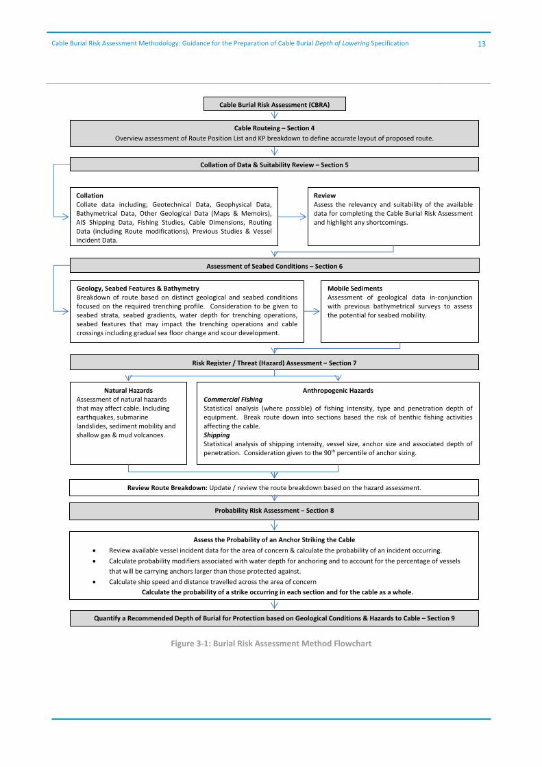
An outline of the proposed method is given in Figure 3‐1 with references to the appropriate sections which contain further detail.
The new CBRA method works in the opposite direction to the BPI method. Once the site conditions have been determined and a risk register developed, the target depth of lowering is specified. The number of vessels carrying anchors large enough to exceed this than this is then determined and the probability of a strike on the cable calculated.
The calculated probability is then assessed by key stakeholders, including a review of the implications on the whole life cost of the cable. Defining the acceptable level of risk is difficult and will be an area were significant discussion and review should be anticipated. A discussion on acceptable risks is included in Section 8.9.
Cable Burial Risk Assessment Methodology: Guidance for the Preparation of Cable Burial Depth of Lowering Specification
13
Figure 3‐1: Burial Risk Assessment Method Flowchart
Cable Burial Risk Assessment (CBRA)
Cable Routeing – Section 4
Overview assessment of Route Position List and KP breakdown to define accurate layout of proposed route.
Collation of Data & Suitability Review – Section 5
Collation Collate data including; Geotechnical Data, Geophysical Data, Bathymetrical Data, Other Geological Data (Maps & Memoirs), AIS Shipping Data, Fishing Studies, Cable Dimensions, Routing Data (including Route modifications), Previous Studies & Vessel Incident Data.
Review Assess the relevancy and suitability of the available data for completing the Cable Burial Risk Assessment and highlight any shortcomings.
Assessment of Seabed Conditions – Section 6
Geology, Seabed Features & Bathymetry Breakdown of route based on distinct geological and seabed conditions focused on the required trenching profile. Consideration to be given to seabed strata, seabed gradients, water depth for trenching operations, seabed features that may impact the trenching operations and cable crossings including gradual sea floor change and scour development.
Mobile Sediments Assessment of geological data in‐conjunction with previous bathymetrical surveys to assess the potential for seabed mobility.
Risk Register / Threat (Hazard) Assessment – Section 7
Natural Hazards Assessment of natural hazards that may affect cable. Including earthquakes, submarine landslides, sediment mobility and shallow gas & mud volcanoes.
Anthropogenic Hazards Commercial Fishing Statistical analysis (where possible) of fishing intensity, type and penetration depth of equipment. Break route down into sections based the risk of benthic fishing activities affecting the cable. Shipping Statistical analysis of shipping intensity, vessel size, anchor size and associated depth of penetration. Consideration given to the 90th percentile of anchor sizing.
Review Route Breakdown: Update / review the route breakdown based on the hazard assessment.
Probability Risk Assessment – Section 8
Quantify a Recommended Depth of Burial for Protection based on Geological Conditions & Hazards to Cable – Section 9
Assess the Probability of an Anchor Striking the Cable
Review available vessel incident data for the area of concern & calculate the probability of an incident occurring.
Calculate probability modifiers associated with water depth for anchoring and to account for the percentage of vessels
that will be carrying anchors larger than those protected against.
Calculate ship speed and distance travelled across the area of concern
Calculate the probability of a strike occurring in each section and for the cable as a whole.
Cable Burial Risk Assessment Methodology: Guidance for the Preparation of Cable Burial Depth of Lowering Specification
14
4 Cable routeing
Cable routeing is the first and most efficient method for mitigating threats to a subsea cable. A balance will have to be maintained between minimising the cable length and avoiding hazards. During routeing, avoiding seabed features that might make burial operations difficult, anchorages, or major shipping lanes etc. or following features that can be easily trenched should both be considered.
It is not considered appropriate to present a detailed methodology on how to route a cable. The CBRA method document should be used at each stage of cable routeing to check that the selected route can be economically and practically installed and to assist in the cost benefit analysis of different route options.
The importance of ensuring that any risk assessment is completed along the final design route cannot be understated. Survey data, shipping information and fishing studies for cable route installation are usually acquired in the early stages of conceptual design and for the preparation of environmental statements. The final cable routeing may not be along the original survey route centreline, it is therefore important that all engineers involved in the cable installation design are fully aware of the data extents and how they relate to the final cable route.
Cable Burial Risk Study: Guidance for Preparation of Cable Burial Specification
15
5 Data collation and review
Acquisition of survey data, particularly for wind farm array cables, has been found to be of variable quality, within wind farms there is likely to be a significant investment in acquiring data for turbine foundation design, including deep boreholes and detailed geological models. The power cables will be installed in the top 1m to 2m and data suitable for foundation design will rarely provide the required data resolution in the near surface. Evidence from wind farms already constructed indicates that significant delays have occurred during cable trenching operations and this may be partially attributed to poor survey specification.
The objective of the site survey for offshore cable projects is to obtain sufficient reliable seabed information on the site conditions to permit the safe and economic design and installation of permanent works. Detailed data needs to be obtained for the total length of the planned cable route, covering a corridor of sufficient width to provide adequate information for the design of the cable route as well as installation and operation related activities, taking into account possible route adjustments due to subsequent findings. With the aim of meeting this objective there are a number of industry guidelines which have been produced, such as SUT4 and DNV5.
Offshore surveys are required at varying stages of the project. These stages are as follows:
Project Planning/feasibility survey
Engineering survey for detailed design
Installation and commissioning (both pre‐installation and post installation)
Operational maintenance survey
Due to the requirements of each stage, the survey scope will differ with the engineering survey being typically more detailed than the feasibility survey and including specialist surveys such as UXO. Although the scope of the surveys may differ the key drivers will be similar. These key drivers for the survey can be divided into 3 categories; man‐made features, natural features and subsurface geological features.
A review of burial and survey techniques for telecommunications, oil and gas, as well as interconnector cables has been undertaken with the objective of identifying any potential alternative techniques suitable for offshore wind farm projects. With regard to surveys, a number of key differences were noted (as well as many similarities), of particular interest is the approach to geotechnical sample spacing. Telecommunications’ cable sample frequency is generally quite wide, in the order of 5‐10 km between samples; however, in contrast the sample frequency for trenched pipelines has an average spacing of 0.5 km to 1 km, with additional tests for features. It is noted that offshore wind farm surveys are moving towards this targeted testing regime, to provide the advantage required to gain the most from the surveys.
In addition to the geophysical and geotechnical surveys which give information on the physical properties of the cable route, other information is required for a thorough risk assessment, this includes fishing intensity, fishing methods, commercial shipping traffic, leisure activities, dredging and historical records of
4 SUT, 2014, Offshore site investigation and Geotechnical Committee, Guidance Notes for the Planning and Execution of a geophysics and geotechnical ground Investigation for Offshore Renewable Energy Developments 5 DNV, 2014, Subsea Power Cables in Shallow Water Renewable Energy Applications, recommended practice DNV‐RP‐J301
Cable Burial Risk Assessment Methodology: Guidance for the Preparation of Cable Burial Depth of Lowering Specification
16
incidents in the area. Acquiring data over a longer time period should also be considered in order to better understand changes to the seabed from mobile sediments, and changes in ship and fishing patterns.
The following information is considered essential for a complete and thorough review:
Route Specific Geotechnical Data, targeted at depth for cable burial - PCPT to nominal 5m depth below seabed at appropriate intervals along the proposed route
and/or where subbottom profiling show differences in soil condition and within the array area (subject to array geometry and cable routing).
- Direct sampling to nominal 5m depth below seabed at appropriate intervals along the proposed route and within array area (subject to array geometry and cable routing), might be Vibrocore, Gravity Core, Piston Core, Borehole or similar.
- Geotechnical laboratory testing on selected samples to confirm engineering properties of sediments.
Geophysical Data targeted at depth for cable burial - High Resolution Multi‐beam Swathe (MBES) Survey to establish the bathymetry and identify
seabed morphology along and within the route corridor for the export cable and within the array area.
- Side Scan Sonar to locate and determine the nature and geometry of seabed features - Magnetometer survey to locate metallic obstructions - Sub‐bottom profiling to detail on the structure of sediments and differentiate between
sediment units within the top 5m of the seabed.
Burial Assessment Surveys,
Bathymetric Data,
Regional Geological Data (Maps & Memoirs),
AIS Shipping Data,
Fishing Studies,
Cable Dimensions,
Routeing Data (including Route modifications),
Previous Studies,
Vessel Incident Data.
Cable Burial Risk Assessment Methodology: Guidance for the Preparation of Cable Burial Depth of Lowering Specification
17
6 Assessment of seabed conditions
With the cable route confirmed and appropriate survey data acquired, any Burial Risk Assessment begins with a detailed analysis of the seabed conditions along the route. The route should be broken down into sections based on distinct geological and seabed conditions with a focus on the trenchability of the conditions and the potential penetration of anchors and fishing gear. Consideration should be given to:
Soil Profile, to an appropriate depth for cable installation
Seabed gradients, which may affect trenchability or, when associated with sandwaves and megaripples, can cause cable free spans
Water depth which can affect the selection of trenching too and the likelihood of anchoring or fishing operations
Seabed features such as sand waves and ripples, patterned ground, clay, mud hard rock platforms and boulder fields.
Annex 1 habitats such as Sabellaria reef, cobble reef, sand banks etc
Potential mobile features, such as sandwaves, sandbanks etc, which may affect the cable later in its operational life.
Gradual sea floor change, scour development and geo‐hazards like seabed slides etc.
Crossing with other subsea infrastructure
The geological conditions along the cable route will determine the depth and method of burial, whilst some conditions will present a hazard to the cable and these are addressed in the Burial Risk Assessment.
Cable Burial Risk Assessment Methodology: Guidance for the Preparation of Cable Burial Depth of Lowering Specification
18
7 Risk Register / Threat Assessment
In order to specify an appropriate Depth of Lowering for subsea power cables a threat assessment should be conducted, this is best done by the preparation of a risk register which considers both the likelihood and consequence of external threats to the cable. An example risk register for a UK Round 3 offshore wind farm project is included in Appendix A, this should be revisited for the particular cable being considered. Threats to the cable which might use cable burial as mitigation are briefly discussed in the following sections.
7.1 Natural
7.1.1 Sediment Mobility
Sediment mobility is not in itself a threat to cable integrity. However, where cable burial has been used as mitigation against another external threat; for example, fishing activity; sediment mobility can result in exposure or additional covering of the cable over time, therefore the risk profile will change over time with increased risk from snagging or cable failure due to strumming of cable spans. Most underwater areas are exposed to a net sediment deposition and the seabed can therefore not be regarded as a static floor with mobile sand moving across. Often it will be the situation that a dune or ripple moves laterally as well as vertically when it progress. This means that the natural development of a cable on a relatively flat seabed will be to bury itself rather than be exposed. This will of course depend on local conditions, but this could be the base assumption.
Sediment mobility along a cable route can be determined; however, it requires multiple accurate bathymetric surveys to be completed and presented relevant to the same datum. The surveys should ideally be completed a number of times, at the same and different times of year recording if possible significant weather events between surveys.
7.1.2 Seismic Activity
Although not considered a significant risk around the UK, where cables are installed in seismically active areas, bathymetric and sub‐bottom profile data should be inspected for evidence of surface expressions of faulting. Fault movement might increase the length of cable required, causing tension or spanning of the cable.
Cable burial cannot normally be used to protect from damage due to ground movement, additional slack cannot normally be laid into a trench, and the constraint of backfill material will not allow the cable to move across a fault.
Alternative cable routing should be considered in order to avoid active faults.
Where the risk from seismic activity cannot be fully avoided, any future damage is likely to be treated as Force Majeure.
7.1.3 Submarine Landslide
Where evidence of submarine landslides is identified on survey data, cable routeing should be carefully considered. Dedicated geohazard studies should be completed. Cable burial can only protect from

Cable Burial Risk Assessment Methodology: Guidance for the Preparation of Cable Burial Depth of Lowering Specification
19
submarine landslides where the base of the potential slide can be identified and the cable buried below this level.
Particular care should be taken when burying cable at the top of a slope that shows evidence of previous slides. The trenching operations may remove material which results in slope instability.
Where the risk from submarine landslides cannot be fully avoided, any future damage is likely to be treated as Force Majeure.
7.2 Anthropogenic
7.2.1 Dredging/Aggregate Extraction/Subsea Mining/Dumping
Dredging and aggregate extraction can pose a threat to submarine cables; however, cable burial is not recommended for risk reduction. Within UK waters, all active and historical dredging are known and are covered by very detailed surveys to allow a certain amount of sediment to remain once a certain point is reached. All disposal sites are also known, these should be avoided (if possible) due to heavy metal contamination from port dredging disposal.
Where aggregate extraction is occurring, cable routes should avoid these areas; alternatively a suitable exclusion zone should be agreed with consenting authorities and the owners of the extraction license. This is more likely to be achieved for future extraction sites.
Where a cable crosses a shipping lane or harbour approach that will be dredged to maintain access, it is recommended that cable installation is conducted immediately after the channel is dredged to its maximum depth. Port authorities should also be consulted over plans for future expansion and allowance made for burial below any future dredging depths.
Historical dumping grounds can also present a hazard to cables and the environment due to the potential for contamination and unknown obstructions. They should generally be avoided.
7.2.2 Other Cables, Umbilical, Pipelines
Where it is possible to foresee the requirement for other cables, pipelines or umbilicals to cross the proposed cable, it may be possible to increase the burial depth of the cable with the available tools in order to allow the future products to also be buried. Whilst the onus is on the future cable or pipeline owner to provide appropriate protection, a collaborative approach is recommended using suitable crossing agreements which include appropriate risk assessments, as suggested by the ICPC Recommendations.
7.2.3 Benthic Fishing
Using AIS, Maritime and Coastguard Agency vessel traffic information and VMS data (noting that vessels of less than 15m are not presently required to carry AIS transponders) and with consultation of local and national fisheries organisations, it is possible to ascertain the size of the fishing fleet working along a proposed cable route. The size of fishing vessels and their fishing methods can be estimated.
Cable Burial is considered an effective means of protecting a cable from fishing activity. Consideration should also be made to changes in fishing patterns once the wind farm and associated cables are constructed.
Cable Burial Risk Assessment Methodology: Guidance for the Preparation of Cable Burial Depth of Lowering Specification
20
7.2.4 Shipping
Errant anchoring from shipping is perceived as a significant threat to unburied or shallow buried cables. However the magnitude of this risk is often exaggerated and the method used in this document will attempt to quantify it. As for fishing, even shallow cable burial is often considered the most cost effective mitigation against this external threat. Consideration should also be made to changes in shipping patterns once the wind farm is constructed. Grounding of ships in shallow water may also present a hazard.
7.2.5 Exclusions
As this document is focused on the mitigation of risk by burial, there are a number of hazards to cables that are not covered by this Guidance, but will, however, need to be addressed on a project by project basis. For example, unexploded ordnance (UXO) is a particular hazard to marine projects around the UK and specific risk assessments and mitigations (avoidance or removal) need to be considered. Similarly, construction activity also presents a significant hazard to installed cables with the vast majority of cable insurance claims relating to damage during construction. Project specific working procedures and protocols need to be developed to ensure that damage to cables is avoided.
7.3 Risk Mitigation
Once all hazards to the cable have been identified, an assessment on the suitability of cable burial as a mitigation of the risk should be made.
In most situations cable burial is anticipated to be the most effective mitigation method for fishing and shipping with route modification or exclusion zones for mitigating the risk from dredging/subsea mining and environmental threats.
Cable Burial Risk Study: Guidance for Preparation of Cable Burial Specification
21
8 Probabilistic risk assessment process
8.1 Protection from Shipping
Ships in transit do not anchor under normal conditions; planned anchoring is normally within a designated anchorage area. A vessel anchoring outside a designated anchorage would normally be expected to inspect charts and select a location free of seabed infrastructure; therefore, the risk from anchoring lies in the occasions where a vessel is forced to anchor due to a mechanical failure or the need to prevent a collision.
8.1.1 Interconnector, Export or Inter Array Cables?
The type of cable should be carefully considered when conducting a risk assessment, particularly if the process of construction is likely to affect the pattern of vessel movement.
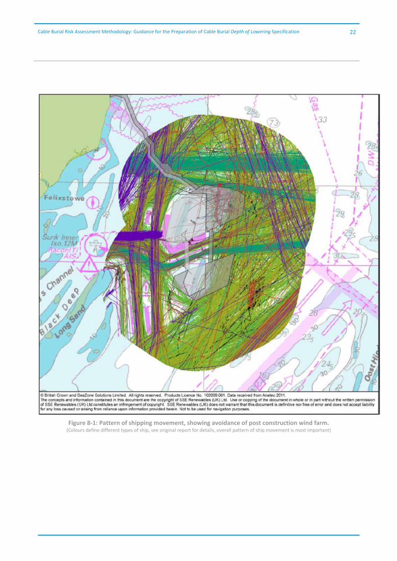
After the construction phase, offshore wind farms are protected by exclusion zones according to local legislation which should be taken into consideration in making the burial risk assessment; however, evidence from the Greater Gabbard Wind Farm in the UK waters of the North Sea, where no exclusion zones are in place, indicates that commercial shipping has been avoiding the wind farm. Figure 8‐1, taken from the Galloper Offshore Wind farm Environmental Statement6 shows an AIS data set acquired after completion of the Greater Gabbard wind farm. It can be seen that all significant traffic is now avoiding the site.
Based on this observation, it could be reasonable to assume that all commercial shipping may routinely avoid wind farms; therefore, the risk assessment should consider this and account for the potential re‐routeing of large vessels away from the area. For inter‐array cables this might mean that no threat from commercial shipping is anticipated. However, it should also be highlighted that most Round 1 and Round 2 sites were selected by the Crown Estate in areas where there was no or little shipping activity to avoid conflict i.e. between Traffic Separation Schemes (TSS). The only craft that will stray out of the TSS areas are that of service boats, fishing vessels and pleasure craft, which do not have the anchoring capabilities of the larger vessels which are contained within the TSS scheme. Therefore for Round 3 wind farms or for other sites in Europe, it could be that the commercial shipping pattern is significantly different compared to Round 1 and Round 2 wind farms.
Interconnector and Export cables will probably not benefit from this protection, in fact an export cable might be subject to a greater threat due to the routeing of vessels around the wind farm area. It is recognised that the wind farms built to date, have been sited to avoid conflict with major shipping lanes where possible; however, some of the proposed Round 3 sites are of a significant size and it remains to be seen if commercial vessels will pass through the sites rather than route around them.
6 Royal Haskoning (2011), Galloper Wind Farm Project Environmental Statement – Chapter 16: Shipping and Navigation, Galloper Wind Farm Limited
Cable Burial Risk Assessment Methodology: Guidance for the Preparation of Cable Burial Depth of Lowering Specification
22
Figure 8‐1: Pattern of shipping movement, showing avoidance of post construction wind farm. (Colours define different types of ship, see original report for details, overall pattern of ship movement is most important)
Cable Burial Risk Assessment Methodology: Guidance for the Preparation of Cable Burial Depth of Lowering Specification
23
8.2 Protection from all vessels?
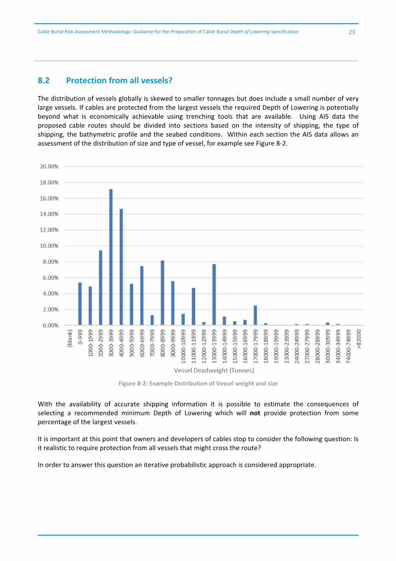
The distribution of vessels globally is skewed to smaller tonnages but does include a small number of very large vessels. If cables are protected from the largest vessels the required Depth of Lowering is potentially beyond what is economically achievable using trenching tools that are available. Using AIS data the proposed cable routes should be divided into sections based on the intensity of shipping, the type of shipping, the bathymetric profile and the seabed conditions. Within each section the AIS data allows an assessment of the distribution of size and type of vessel, for example see Figure 8‐2.
Figure 8‐2: Example Distribution of Vessel weight and size
With the availability of accurate shipping information it is possible to estimate the consequences of selecting a recommended minimum Depth of Lowering which will not provide protection from some percentage of the largest vessels.
It is important at this point that owners and developers of cables stop to consider the following question: Is it realistic to require protection from all vessels that might cross the route?
In order to answer this question an iterative probabilistic approach is considered appropriate.

Cable Burial Risk Assessment Methodology: Guidance for the Preparation of Cable Burial Depth of Lowering Specification
24
8.3 Probabilistic Method
In order to determine an acceptable, economically and practically achievable Depth of Lowering it is important to be able to quantify the risk to the cable from all vessels.
The probabilistic method proposed is a variation of a method originally proposed by DNV as part of the draft version of Ref 6, it has not been included as part of the final version. A variation of the method was also presented by Dr Claus F. Christensen in 2006, for DNV as part of a presentation on security of cables in the Baltic.
The method has been modified to remove as far as possible any qualitative input. This results in the method potentially being very conservative; the impact of choice of factors is discussed in the following sections. The method evaluates the exposure of the cable to external threats by considering the amount of time a vessel spends within a critical distance of the cable and the probability that a vessel might have an incident that requires the deployment of an anchor. The effect of water depth and bathymetric profile is considered very important and is included as a qualitative factor.
The calculation for the probability of a cable strike is given by:
Where:
Ptraffic : probability modifier based on the tolerable level of risk
Pwd : probability modifier for nature and depth of seabed Vship : ship speed (metre/hr) Dship : distance travelled by ship in area under consideration (metre)
Pincident : probability of incident occurring for that vessel size and type
8670 hrs : factor to annualise the results.
The determinations of the variables are discussed in more detail in the following sections.
It is highlighted that this assessment only identifies the probability of an anchor striking a cable. An anchor strike will not necessarily result in damage to the cable. Cables are constructed with additional armour protection to protect from external aggression. It may be possible for a cable to be struck a number of times without instantaneous critical damage occurring; however, the strike may drag the cable, reducing the depth of burial thus exposing the cable to a higher probability of further strikes. It may also lead to internal weaknesses that result in a future failure.
A worked example, illustrating the use of the method is included for reference in Appendix B.

Cable Burial Risk Assessment Methodology: Guidance for the Preparation of Cable Burial Depth of Lowering Specification
25
8.4 Ptraffic
The probabilistic approach is intended to be iterative; in order to identify a burial depth which results in a
tolerable residual risk it is the value of Ptraffic which is modified as follows:
1. Calculate the value of Pstrike for all vessels (Ptraffic = 1) 2. Agree the value of Pstrike that would be acceptable to the stakeholders 3. Calculate the value of Ptraffic (Scale 0 to 1) which achieves this tolerable level 4. The value of (1‐ Ptraffic) x 100% is the percentage of vessels for which cable burial is required for
protection. 5. The anchor/vessel size required for this percentage of vessels is taken from the appropriate distribution
curve, Figure 8‐3. 6. The required depth of lowering is derived as given in Section 9. 7. If the depth of lowering is considered impractical the acceptable level of risk should be re‐considered.
Note, if the cable burial depth exceeds the penetration depth of the largest anchors identified in the vicinity
of the cable then the probability of a strike is zero (Ptraffic = 0), within the error of the source data. Similarly,
if no shipping is anticipated in the area the probability of a strike is zero (Ptraffic = 0).If the cable is not buried the results of the assessment represent the worst case scenario for cable strikes from any anchoring vessel,
i.e. a cable not buried (Ptraffic = 1).
Figure 8‐3: Selection of Ptraffic
The probabilistic analysis should be completed iteratively, changing the value of Ptraffic to determine the minimum Depth of Lowering which results in a probability of cable strike which is acceptable to the developers/owners, or determines the risk at an economically achievable Depth of Lowering.
Cable Burial Risk Assessment Methodology: Guidance for the Preparation of Cable Burial Depth of Lowering Specification
26
The selection of the factor will be driven by the risk profile which is acceptable to the developer or cable owner. Where a third party will take over the cable once it is installed the residual risk can be used to inform the potential for incidents during the life span of the cable and hence an estimate of whole life costs. As mentioned above the very limited infield shipping traffic (Ptraffic≈0) in many cases would make further analysis on array cables redundant.
In addition the risk calculation may be repeated after cable installation and burial, or later in the life time of the cable when seabed levels may have changed. The depth of the cable below seabed should be used to inform the percentage of vessels which carry anchors large enough to hit the cable. This defines the value of Ptraffic; therefore, the actual residual risk to the cable can be calculated. This can inform the requirement for or specification of any remedial operations on the cable.
8.5 Pwd
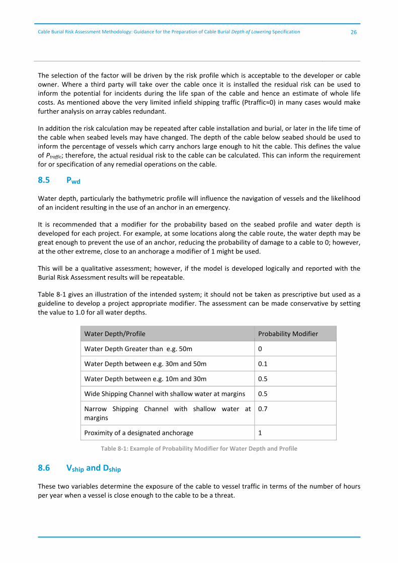
Water depth, particularly the bathymetric profile will influence the navigation of vessels and the likelihood of an incident resulting in the use of an anchor in an emergency.
It is recommended that a modifier for the probability based on the seabed profile and water depth is developed for each project. For example, at some locations along the cable route, the water depth may be great enough to prevent the use of an anchor, reducing the probability of damage to a cable to 0; however, at the other extreme, close to an anchorage a modifier of 1 might be used.
This will be a qualitative assessment; however, if the model is developed logically and reported with the Burial Risk Assessment results will be repeatable.
Table 8‐1 gives an illustration of the intended system; it should not be taken as prescriptive but used as a guideline to develop a project appropriate modifier. The assessment can be made conservative by setting the value to 1.0 for all water depths.
Water Depth/Profile Probability Modifier
Water Depth Greater than e.g. 50m 0
Water Depth between e.g. 30m and 50m 0.1
Water Depth between e.g. 10m and 30m 0.5
Wide Shipping Channel with shallow water at margins 0.5
Narrow Shipping Channel with shallow water at margins
0.7
Proximity of a designated anchorage 1
Table 8‐1: Example of Probability Modifier for Water Depth and Profile
8.6 Vship and Dship
These two variables determine the exposure of the cable to vessel traffic in terms of the number of hours per year when a vessel is close enough to the cable to be a threat.
Cable Burial Risk Assessment Methodology: Guidance for the Preparation of Cable Burial Depth of Lowering Specification
27
Vship is calculated using one of two methods. Either from the AIS data as the average vessel speed in metres per hour, taken from the nearest AIS point. Alternatively, it could be based on the overall average speed of all vessels in the area. Where no suitable data is available a speed of 4 knots might be used, vessels travelling faster than this are unlikely to deploy an anchor, using this value for all vessels crossing the cable route will give a conservatively large exposure time.
Dship is the distance travelled by the vessel when it is close enough to the cable to be a threat. A ship is only a threat if it deploys an anchor and drags it on to the cable. The drag distance can be estimated using an energy absorption calculation based on the vessel’s weight, speed and anchor holding capacity in the anticipated conditions. Once a vessel is beyond this distance from the cable it no longer poses a threat to
the cable. Two alternatives are proposed to determine Dship.
Firstly, the anchor size for each vessel track could be determined, and then the anchor drag distance calculated. From this, the duration that the vessel spends within the drag distance of the cable can be calculated. The duration for all vessels would be summed for each section of the cable route. This method requires intensive calculation for each AIS track, even a short route may be crossed by several thousand tracks each month.
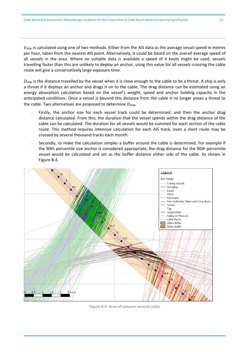
Secondly, to make the calculation simpler a buffer around the cable is determined. For example if the 90th percentile size anchor is considered appropriate, the drag distance for the 90th percentile vessel would be calculated and set as the buffer distance either side of the cable. As shown in Figure 8‐4.
Figure 8‐4: Area of concern around cable

Cable Burial Risk Assessment Methodology: Guidance for the Preparation of Cable Burial Depth of Lowering Specification
28
Choosing the area of concern can affect the results of the risk calculation significantly. The selection of a larger buffer is more conservative, increasing the exposure time for the cable.
Vship and Dship together give a time of exposure for the cable for one vessel, when summed for every vessel and the entire cable route (or the section being considered) the exposure time per year for the cable is calculated.
8.7 Pincident
Pincident has the greatest influence on the outcome of the probabilistic assessment. It is critical that sufficient time is spent reviewing the probability that a vessel may have an incident which might require the use of an anchor or involves an anchor.
It is recognised that developing an accurate value for the number of incidents is complex and that the availability of information varies significantly from location to location.
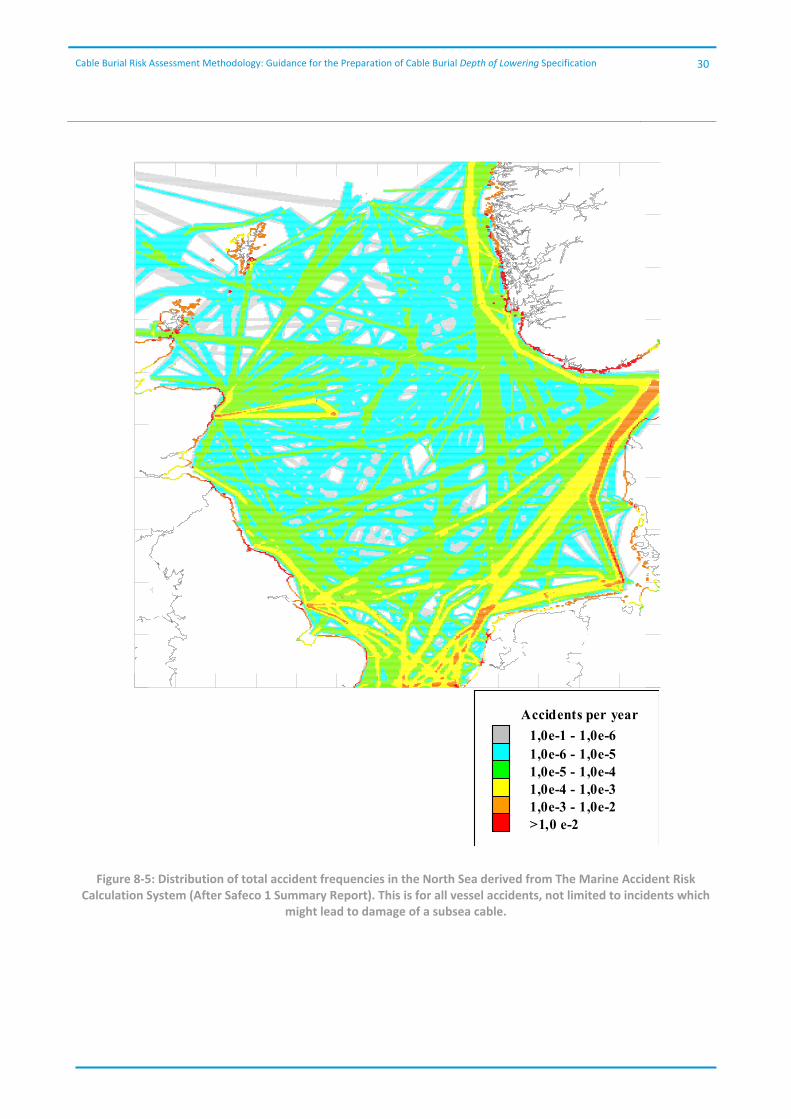
In some locations the availability of incident data from National Authorities allows assessment of the number of incidents for a certain vessel type or class. For example, incidents investigated by the Marine Accident Investigation Board (UK) between 1995 and 2012 which might have led to use of an anchor are illustrated in Table 8‐2 and Figure 8‐6, these incidents include machinery failures, groundings and fires. The publically available information includes the size of vessel, its type and the nature of the incident. From this, the probability of a vessel of certain size and certain type having an incident that might cause damage to a cable can be estimated.
Alternatively, Lloyds Register annually publish both World Casualty Statistics and World Fleet Statistics which can be used to determine a frequency rate for a given region.
Where statistical data on the number of incidents is not available, figures from literature might be used; however, careful consideration is recommended to ensure unrealistically low or high values are not artificially created.
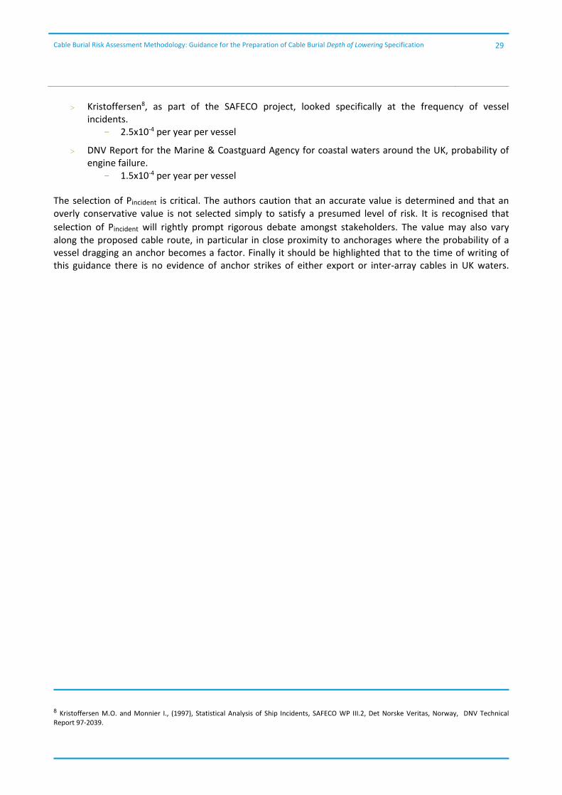
Figure 8‐5 taken from the SAFECO 1 Summary report illustrates the distribution of total accident frequencies in the North Sea; this is for all accidents, it is not limited to those that might lead to damage of a subsea cable. Further, this figure illustrates that the number of accidents increases where shipping intensity is highest; however, with regard to the selection of Pincident care should be taken that the value represents the probability of an accident occurring for any one vessel. The shipping intensity is handled by the count of ships in the method.
Some examples of values from literature are given here:
DNV‐RP‐F1077, gives a figure for the Probability of loss of control on board a ship, this figure is reportedly confirmed by two other papers.
- 2.0x10‐4 per year per vessel
The same document also gives a more conservative value based on the frequency of machinery breakdown of 2.0x10‐5 per hour of operation per vessel
7 DNV, October 2010, Recommended Practice DNV‐RP‐F107, Risk Assessment of Pipeline Protection
Cable Burial Risk Assessment Methodology: Guidance for the Preparation of Cable Burial Depth of Lowering Specification
29
Kristoffersen8, as part of the SAFECO project, looked specifically at the frequency of vessel incidents.
- 2.5x10‐4 per year per vessel
DNV Report for the Marine & Coastguard Agency for coastal waters around the UK, probability of engine failure.
- 1.5x10‐4 per year per vessel
8 Kristoffersen M.O. and Monnier I., (1997), Statistical Analysis of Ship Incidents, SAFECO WP III.2, Det Norske Veritas, Norway, DNV Technical Report 97‐2039.
The selection of Pincident is critical. The authors caution that an accurate value is determined and that an overly conservative value is not selected simply to satisfy a presumed level of risk. It is recognised that
selection of Pincident will rightly prompt rigorous debate amongst stakeholders. The value may also vary along the proposed cable route, in particular in close proximity to anchorages where the probability of a vessel dragging an anchor becomes a factor. Finally it should be highlighted that to the time of writing of this guidance there is no evidence of anchor strikes of either export or inter‐array cables in UK waters.
Cable Burial Risk Assessment Methodology: Guidance for the Preparation of Cable Burial Depth of Lowering Specification
30
1,0e-1 - 1,0e-6
Accidents per year
1,0e-6 - 1,0e-51,0e-5 - 1,0e-41,0e-4 - 1,0e-31,0e-3 - 1,0e-2>1,0 e-2
Figure 8‐5: Distribution of total accident frequencies in the North Sea derived from The Marine Accident Risk Calculation System (After Safeco 1 Summary Report). This is for all vessel accidents, not limited to incidents which
might lead to damage of a subsea cable.

Cable Burial Risk Assessment Methodology: Guidance for the Preparation of Cable Burial Depth of Lowering Specification
31
Vessel Deadweight
Cargo
ship
Other type of ship
Passenger ship
Search and rescue
vessel
Tanker
Tug
Unknown type of ship
Vessel ‐ Engaged in
diving operations
Vessel ‐ Engaged in
dredging or
underwater
operations
Vessel ‐ Engaged in
military operations
Vessel ‐ Fishing
Vessel ‐ Towing
Vessel ‐ Towing and
tow‐len
gth > 200m or
tow‐breadth
>25m
(blank) 0.0% 0.0% 0.0% 0.0% 0.0% 0.0% 0.0% 0.0% 0.0% 0.0% 0.0% 0.0% 0.0%
0‐2499 7.4% 1.1% 0.0% 2.5% 1.5% 0.3% 0.5% 0.0% 0.1% 0.1% 0.1% 0.2% 0.3%
2500‐4999 26.6% 0.5% 0.2% 0.0% 9.4% 0.0% 0.3% 0.0% 0.3% 0.0% 0.0% 0.0% 0.0%
5000‐7499 5.1% 0.0% 3.9% 0.0% 4.2% 0.0% 0.0% 0.0% 0.2% 0.0% 0.0% 0.0% 0.0%
7500‐9999 6.2% 1.2% 5.9% 0.0% 1.0% 0.0% 0.0% 0.1% 0.0% 0.0% 0.0% 0.0% 0.0%
10000‐12499 5.2% 0.0% 0.9% 0.0% 0.2% 0.0% 0.0% 0.0% 0.0% 0.0% 0.0% 0.0% 0.0%
12500‐14999 8.3% 0.0% 0.0% 0.0% 0.9% 0.0% 0.0% 0.0% 0.0% 0.0% 0.0% 0.0% 0.0%
15000‐17499 2.7% 0.0% 0.0% 0.0% 0.9% 0.0% 0.0% 0.0% 0.0% 0.0% 0.0% 0.0% 0.0%
17500‐19999 0.3% 0.0% 0.0% 0.0% 0.2% 0.0% 0.0% 0.0% 0.0% 0.0% 0.0% 0.0% 0.0%
22500‐24999 0.0% 0.0% 0.0% 0.0% 0.3% 0.0% 0.0% 0.0% 0.0% 0.0% 0.0% 0.0% 0.0%
25000‐27499 0.2% 0.0% 0.0% 0.0% 0.0% 0.0% 0.0% 0.0% 0.0% 0.0% 0.0% 0.0% 0.0%
27500‐29999 0.0% 0.0% 0.0% 0.0% 0.0% 0.0% 0.1% 0.0% 0.0% 0.0% 0.0% 0.0% 0.0%
30000‐32499 0.1% 0.0% 0.0% 0.0% 0.3% 0.0% 0.0% 0.0% 0.0% 0.0% 0.0% 0.0% 0.0%
32500‐34999 0.2% 0.0% 0.0% 0.0% 0.0% 0.0% 0.0% 0.0% 0.0% 0.0% 0.0% 0.0% 0.0%
72500‐74999 0.0% 0.0% 0.0% 0.0% 0.1% 0.0% 0.0% 0.0% 0.0% 0.0% 0.0% 0.0% 0.0%
80000‐82499 0.1% 0.0% 0.0% 0.0% 0.0% 0.0% 0.0% 0.0% 0.0% 0.0% 0.0% 0.0% 0.0%
Table 8‐2: Example Vessel Type and Size Distribution
Cable Burial Risk Assessment Methodology: Guidance for the Preparation of Cable Burial Depth of Lowering Specification
32
Figure 8‐6: MAIB Incident Data 1995 to 2012 for incidents that might result in use of anchor (but did not necessarily do so).
8.8 Exclusions and Limitations
The probabilistic assessment as presented is a simplified method; it excludes a number of variables that have been used by other authors in the assessment of risk to cables. It also contains a number of limitations. The following is a summary:
8.8.1 Prevailing Metocean Conditions
Other authors have included a variable in the risk assessment calculation to account for the anticipated weather conditions such that if the incident occurs on one side of the cable the vessel may either be blown onto or away from the cable.
This has been omitted from the proposed methods, making the results more conservative. It is felt that due to the statistical basis of metocean data and because directionality of vessel movement is not otherwise considered in the assessment, it would be too inaccurate to include.
Cable Burial Risk Assessment Methodology: Guidance for the Preparation of Cable Burial Depth of Lowering Specification
33
8.8.2 Human Factor
Other authors have considered a variable based on a human factor. The factor is used to indicate that every occurrence of a vessel incident involving an anchor does not result in uncontrolled anchoring without regard to subsea infrastructure. It is very difficult to determine this variable, as such it has been omitted. This makes the method as proposed more conservative by assuming the worst case in every anchor incident.
8.9 Acceptable Risk
The probabilistic risk assessment as presented gives only an indication of the residual risk to the cable from shipping after the cable has been buried.
The risk from fishing is considered negligible where the minimum burial depth is achieved against the blanket Depth of Lowering where fishing is anticipated.
The change in risk due to sediment mobility will be determined separately.
The level of risk that is acceptable is primarily a decision for the developer and the selection of an appropriate Depth of Lowering which provides adequate protection will reflect the cable owners/operators attitude to risk.
A number of other guidelines give suggested levels for acceptable risk; however, these have tended to focus on oil and gas installations where damage to subsea infrastructure has the potential to cause significant environmental damage. Damage to a power cable may have significant economic consequences to the owner/operator or any third party using the cable for export purposes; however, environmental damage is highly unlikely.
The target levels as proposed by DNV in OS‐F1019 are considered a conservative starting point; they have been determined with a focus on safety and potentially significant environmental impacts not on quality or service continuity. Owner/operators and developers should review these levels with regard to their own requirements.
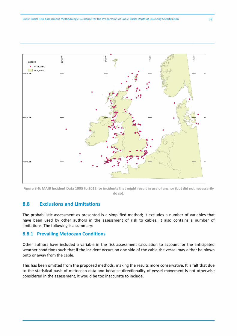
DNV recommend the target annual return probabilities, with a conservative focus on human and environmental safety, for different consequence levels as described in Table 8‐3.
Consequence Level Low Medium High Very High
Target annual probability for acceptance
10‐2 10‐3 10‐3 10‐4
Table 8‐3: Nominal annual target failure probabilities (after DNV‐OS‐F101, Section 2, 500, Table 2‐5)
9 DNV, August 2012, Offshore Standard DNV‐OS‐F101, Submarine Pipeline Systems
Cable Burial Risk Assessment Methodology: Guidance for the Preparation of Cable Burial Depth of Lowering Specification
34
9 Specifying Depth of Lowering
Having identified the size of vessel, larger than which the risk to the cable is tolerable, the potential depth of penetration of the associated anchor must be determined. This must be combined with the required Depth of Lowering from other factors such as fishing and changes to the seabed in order to specify the Depth of Lowering.
9.1 Depth of Lowering Definition
The authors have noted that the terms burial depth, depth of cover, target depth and trench depth are often used interchangeably by different operators, developers, consultants and contractors. For clarity the following definitions as shown in Figure 9‐1, all referenced from mean seabed, are used in this document and are suggested for cable burial risk assessments. Note that the two target depths are installation parameters based on known protection method and site conditions, and as such are not covered by this document.
Recommended Minimum Depth of Lowering – This is the minimum depth recommended for protection from the external threats, it is the direct output of the risk assessment.
Target Depth of Lowering – This is the depth that cable installers should target; specified by the developer. Target Depth of Lowering should be equal to or greater than the recommended minimum Depth of Lowering and may include a factor of safety; it may also be prudent to increase the target Depth of Lowering where the recommended minimum Depth of Lowering is relatively shallow. This will account for instability in burial tools. Where the target Depth of Lowering is not achieved no remedial action would be required as long as the recommended Minimum Depth of Lowering is achieved.
Target Trench Depth ‐ Cable installers should determine the trench depth that they require based on the cable properties and the trenching tool selected to complete the works. This is usually the diameter of the cable plus between 0.1 m and 0.4 m beyond the Target Depth of Lowering.
Depth of Cover ‐ the thickness of material on top of the cable after trenching. It is not normally required for cable protection; however, it may be required by some consenting authorities e.g. BSH in the German Sector where the 2 K10 rule is imposed.
10 A Specification imposed by the Bundesamt für Seeschifffahrt und Hydrographie (BSH) on power cables in the German Sector of the North Sea and Baltic Sea. It stipulates that post cable installation the temperature 0.2m below seabed cannot be more than 2 Kelvin higher than ambient. BSH (2007), Standard, Design of Offshore Wind Turbines, Federal Maritime and Hydrographic Agency, Hamburg and Rostock 2007.

Cable Burial Risk Assessment Methodology: Guidance for the Preparation of Cable Burial Depth of Lowering Specification
35
Figure 9‐1: Definition of Trench Parameters
9.2 Anchor Size
Being designed to penetrate the seabed to achieve a holding capacity, anchors have the potential to be damaging to cable systems. All ships are fitted with anchors that may be deployed either as a temporary mooring as part of a planned procedure, or for safety, should the ship be at risk for some reason (for example loss of power). Anchor size requirements are based on various regulations including those published by Lloyds, American Bureau of Shipping and the International Association of Classification Societies (IACS).
Using the IACS11 rules it is possible to determine the approximate size of anchors that might be used by the vessels crossing the cable routes. The holding power of an anchor is normally determined by the weight of the anchor, which is proportional to the fluke length. The size of anchor required by law on a vessel is determined by the Equipment Number of the vessel, given below:
Where: DWT: Vessel Deadweight B: Moulded breadth, in metres H: Effective height, in metres, from the Summer Load Waterline to the top of the uppermost house A: Area, in square metres, in profile view, of the hull, superstructure and houses above the Summer Load Waterline
11 International Association of Classification Societies (2007); Requirements Concerning Mooring, Anchoring and Towing
Cable Burial Risk Assessment Methodology: Guidance for the Preparation of Cable Burial Depth of Lowering Specification
36
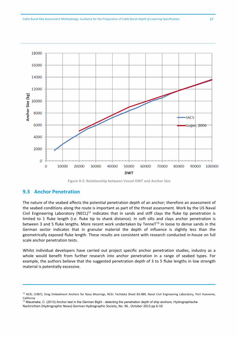
The equipment number is related to the displacement and sail area both above and below the waterline. The calculation includes parameters for breadth and effective height and therefore, the analysis should be considered an approximation; however DWT represents approximately 2/3 of the classification value. Figure 9‐2 illustrates the relationship between vessel DWT and anchor size. It is relevant to note that this relationship correlates well with anchor sizing proposed by Luger (Ref 42) and that IACS rules result in broadly similar anchor sizes to Lloyds and DNV.
Using this relationship and the distribution of vessels crossing the cable route, the distribution of anchor weights can be estimated.
From the commonly available anchor catalogues it is possible to identify the distribution of the fluke length of anchors on vessels crossing the cable route; it should be noted that the fluke length can vary significantly depending on the manufacturer and type of anchor being used, particularly where high holding power anchors (HHP) such as the Pool TW are in use. HHP anchors have been designed to be much smaller in weight for the same performance; however, the penetration depths do not vary with equipment number.
Having identified the fluke length of anchors anticipated in an area the potential penetration depth can be determined.
Cable Burial Risk Assessment Methodology: Guidance for the Preparation of Cable Burial Depth of Lowering Specification
37
Figure 9‐2: Relationship between Vessel DWT and Anchor Size
9.3 Anchor Penetration
The nature of the seabed affects the potential penetration depth of an anchor; therefore an assessment of the seabed conditions along the route is important as part of the threat assessment. Work by the US Naval Civil Engineering Laboratory (NECL)12 indicates that in sands and stiff clays the fluke tip penetration is limited to 1 fluke length (i.e. fluke tip to shank distance). In soft silts and clays anchor penetration is between 3 and 5 fluke lengths. More recent work undertaken by TenneT13 in loose to dense sands in the German sector indicates that in granular material the depth of influence is slightly less than the geometrically exposed fluke length. These results are consistent with research conducted in‐house on full scale anchor penetration tests.
Whilst individual developers have carried out project specific anchor penetration studies, industry as a whole would benefit from further research into anchor penetration in a range of seabed types. For example, the authors believe that the suggested penetration depth of 3 to 5 fluke lengths in low strength material is potentially excessive.
12 NCEL (1987), Drag Embedment Anchors for Navy Moorings, NCEL Techdata Sheet 83‐08R, Naval Civil Engineering Laboratory, Port Hueneme, California 13 Maushake, C. (2013) Anchor test in the German Bight ‐ detecting the penetration depth of ship anchors, Hydrographische Nachrichten (Hydrographic News) German Hydrographic Society, No. 96 , October 2013 pp 6‐10
Cable Burial Risk Assessment Methodology: Guidance for the Preparation of Cable Burial Depth of Lowering Specification
38
9.4 Protection from Sediment Mobility
There are a number of well documented examples where sediment mobility has not been adequately determined resulting in cable exposures and ultimately cable failure due to snagging or abrasion.
Sediment mobility along a cable route can be determined; however, it requires multiple accurate bathymetric surveys to be completed and presented relevant to the same datum. The surveys should ideally be completed a number of times, at the same and different times of year. If possible significant weather events between surveys should also be recorded.
This data can then be used to inform the thickness of mobile sediment and rate of movement.
Where multiple surveys are not available inspection of the bathymetric and sub‐bottom profile data can indicate the thickness of the mobile layer; i.e. the presence of megaripples, sand waves and sandbanks clearly indicate that sediment is mobile, however, assessment of the rate of movement will be difficult and there will be a low confidence in evaluating the impact during the life of the cable.
Ideally cables will be buried below mobile sediment layers; with the mobile layer excluded from the measured Depth of Lowering. This may not be practical in the case of large megaripples, sandwaves or sandbanks.
Where Depth of Lowering below sandwaves is not possible a number of mitigation options are available:
Sympathetic cable routing or micro routing in regards to the feature orientation
Dredging of mobile feature; this is not normally acceptable on a large scale; it may be required in exceptional circumstances
Rock or mattress protection in order to keep the cable protected as mobile features move across the seabed; for installation this may require dredging initially; the presence of rock berms and mattresses may also change the sediment mobility pattern
Repeat cable inspection and remedial trenching; may introduce significant lifetime costs for the cable. It may not be practical where the material underlying the mobile sediment is high strength
It is recognised that multiple surveys across large areas might be costly. If mobile features are identified in the first survey a cost benefit analysis of survey vs. increased burial depth may be required.
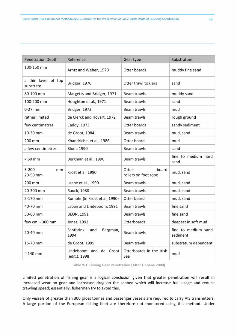
9.5 Protection from Fishing
The penetration of fishing gear into the seabed has been studied in detail by a number of authors. Work by Linnane et al (2000)14 indicates that fishing gear penetration is limited to a maximum of 0.3 m penetration even in soft sediment. Table 9‐1 replicates the summary produced by Linnane. It is recognised that this research is 14 years old and there have been developments in the trawlboard and beam trawl design. A literature review for this project indicates that the focus of research into the impacts of fishing has changed; from the physical impacts to the impact on, and recovery of, biota in the shallow section. This research appears to be focused on the top 0.1 m of seabed.
14 Linnane et al (2000) A Review of Potential Techniques to Reduce the Environmental Impact of Demersal Trawls, Irish Fisheries Investigations (New Series) No. 7.
Cable Burial Risk Assessment Methodology: Guidance for the Preparation of Cable Burial Depth of Lowering Specification
39
Penetration Depth Reference Gear type Substratum
100‐150 mm
Arntz and Weber, 1970 Otter boards muddy fine sand
a thin layer of top substrate
Bridger, 1970 Otter trawl ticklers sand
80‐100 mm Margetts and Bridger, 1971 Beam trawls muddy sand
100‐200 mm Houghton et al., 1971 Beam trawls sand
0‐27 mm Bridger, 1972 Beam trawls mud
rather limited de Clerck and Hovart, 1972 Beam trawls rough ground
few centimetres Caddy, 1973 Otter boards sandy sediment
10‐30 mm de Groot, 1984 Beam trawls mud, sand
200 mm Khandriche, et al., 1986 Otter board mud
a few centimetres Blom, 1990 Beam trawls sand
= 60 mm Bergman et al., 1990 Beam trawls fine to medium hard sand
5‐200 mm 20‐50 mm
Krost et al, 1990 Otter board rollers on foot rope
mud, sand
200 mm Laane et al., 1990 Beam trawls mud, sand
20‐300 mm Rauck, 1988 Beam trawls mud, sand
5‐170 mm Rumohr (in Krost et al, 1990) Otter board mud, sand
40‐70 mm Laban and Lindeboom, 1991 Beam trawls fine sand
50‐60 mm BEON, 1991 Beam trawls fine sand
few cm. ‐ 300 mm Jones, 1992 Otterboards deepest in soft mud
20‐40 mm Santbrink and Bergman, 1994
Beam trawls fine to medium sand sediment
15‐70 mm de Groot, 1995 Beam trawls substratum dependant
~ 140 mm Lindeboom and de Groot (edit.), 1998
Otterboards in the Irish Sea
mud
Table 9‐1: Fishing Gear Penetration (After Linnane 2000)
Limited penetration of fishing gear is a logical conclusion given that greater penetration will result in increased wear on gear and increased drag on the seabed which will increase fuel usage and reduce trawling speed; essentially, fishermen try to avoid this.
Only vessels of greater than 300 gross tonnes and passenger vessels are required to carry AIS transmitters. A large portion of the European fishing fleet are therefore not monitored using this method. Under
Cable Burial Risk Assessment Methodology: Guidance for the Preparation of Cable Burial Depth of Lowering Specification
40
European Union legislation, VMS (Vessel Monitoring System) is a legal requirement for vessels in excess of 15 metres. Vessels automatically transmit vessel identification, date, time, position, course and speed at least every 2 hours. This information can be gathered but only gives an indication of fishing intensity in an area.
Vessels less than 15m are not required to carry tracking devices but are required to report the locations from which they take their catch.
The lack of detailed information on the movement and intensity of smaller fishing vessels limits the effectiveness of any probabilistic approach.
Where sufficiently detailed information on fishing grounds is available or in areas where fishing is excluded, it may be possible to remove the requirement for burial for protection from fishing activity.
Recommendation: Given the limited information on fishing intensity it is recommended that a fixed Depth of Lowering be applied to provide protection from fishing gear based on the seabed strength and the types of fishing gear in use in the region.
9.6 Factor of Safety (FoS)
Having identified the potential penetration depth, the application of a factor of safety to the calculated fishing gear or anchor fluke tip penetration depths is recommended. The reasons for FoS application are as follows:
There will always be an inherent uncertainty in the soil profile along the cable route due to the variability of soil properties from single site investigation points.
The inherent inaccuracies in positioning and resolution of shallow geophysical surveys.
Shipping data is normally based on limited sampling that may not be fully representative of the lifetime of the cable, e.g. with AIS data it is possible to identify a significant drop in shipping activity after the global credit crisis in 2008.
The approximate manner in which anchor sizes are estimated.
The inaccuracy of measurement of Depth of Lowering
The FoS may vary between projects and consideration should be given to the validity of a constant FoS particularly along long export or interconnector cables.
Some of the factors that should be given consideration when selecting appropriate Factors of Safety are given below; the following is given as an example of some areas of thought; it is not comprehensive nor does it indicate the minimum that should be considered.
Where shipping density is relatively high the uncertainty in anchor sizing increases, therefore an increased FoS may be appropriate.
The FoS should be varied based on the quality, appropriateness and distribution of the route survey data.
FoS may vary based on sensitivity and variability checks of seabed strength.
No specific FoS are suggested; it is recommended that stakeholders review their own acceptable risk profile based upon the accuracy of the data utilised for assessment; however indicative values of FoS can be seen
Cable Burial Risk Assessment Methodology: Guidance for the Preparation of Cable Burial Depth of Lowering Specification
41
throughout the worked example in Appendix B. These are based upon the experience and engineering judgement of the persons performing the CBRA.
Where the recommended minimum Depth of Lowering is limited e.g. less than 0.3 m where only fishing is assessed as a threat, a minimum additional clearance of 0.3 m is recommended to avoid a target Depth of Lowering of less than 0.5 m which are difficult to achieve in practice.
In all cases care should be taken not to specify a FoS which results in a target Depth of Lowering which is not economically achievable using the trenching assets available to the market in the anticipated ground conditions.
9.7 Consultation with Trenching Contractors
It is strongly recommended that early engagement with trenching contractors and cable installers is sought during any project development. Use of alternative trenching methodologies, alternative routeing to avoid untrenchable areas and identification of economically and practically achievable Depth of Lowering may save delays later on.
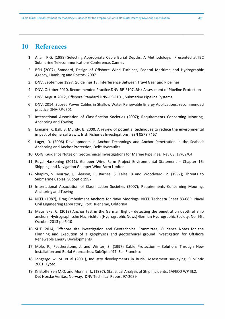
Cable Burial Risk Assessment Methodology: Guidance for the Preparation of Cable Burial Depth of Lowering Specification
42
10 References
1. Allan, P.G. (1998) Selecting Appropriate Cable Burial Depths: A Methodology. Presented at IBC Submarine Telecommunications Conference, Cannes
2. BSH (2007), Standard, Design of Offshore Wind Turbines, Federal Maritime and Hydrographic Agency, Hamburg and Rostock 2007
3. DNV, September 1997, Guidelines 13, Interference Between Trawl Gear and Pipelines
4. DNV, October 2010, Recommended Practice DNV‐RP‐F107, Risk Assessment of Pipeline Protection
5. DNV, August 2012, Offshore Standard DNV‐OS‐F101, Submarine Pipeline Systems
6. DNV, 2014, Subsea Power Cables in Shallow Water Renewable Energy Applications, recommended practice DNV‐RP‐J301
7. International Association of Classification Societies (2007); Requirements Concerning Mooring, Anchoring and Towing
8. Linnane, K, Ball, B, Mundy. B. 2000. A review of potential techniques to reduce the environmental impact of demersal trawls. Irish Fisheries Investigations. ISSN 0578 7467
9. Luger, D. (2006) Developments in Anchor Technology and Anchor Penetration in the Seabed; Anchoring and Anchor Protection, Delft Hydraulics
10. OSIG: Guidance Notes on Geotechnical Investigations for Marine Pipelines. Rev 03, 17/09/04
11. Royal Haskoning (2011), Galloper Wind Farm Project Environmental Statement – Chapter 16: Shipping and Navigation Galloper Wind Farm Limited
12. Shapiro, S. Murray, J, Gleason, R, Barnes, S. Eales, B and Woodward, P. (1997); Threats to Submarine Cables; Suboptic 1997
13. International Association of Classification Societies (2007); Requirements Concerning Mooring, Anchoring and Towing
14. NCEL (1987), Drag Embedment Anchors for Navy Moorings, NCEL Techdata Sheet 83‐08R, Naval Civil Engineering Laboratory, Port Hueneme, California
15. Maushake, C. (2013) Anchor test in the German Bight ‐ detecting the penetration depth of ship anchors, Hydrographische Nachrichten (Hydrographic News) German Hydrographic Society, No. 96 , October 2013 pp 6‐10
16. SUT, 2014, Offshore site investigation and Geotechnical Committee, Guidance Notes for the Planning and Execution of a geophysics and geotechnical ground Investigation for Offshore Renewable Energy Developments
17. Mole, P., Featherstone, J. and Winter, S. (1997) Cable Protection – Solutions Through New Installation and Burial Approaches. SubOptic ’97. San Francisco
18. Jongergouw, M. et al (2001), Industry developments in Burial Assessment surveying, SubOptic 2001, Kyoto
19. Kristoffersen M.O. and Monnier I., (1997), Statistical Analysis of Ship Incidents, SAFECO WP III.2, Det Norske Veritas, Norway, DNV Technical Report 97‐2039
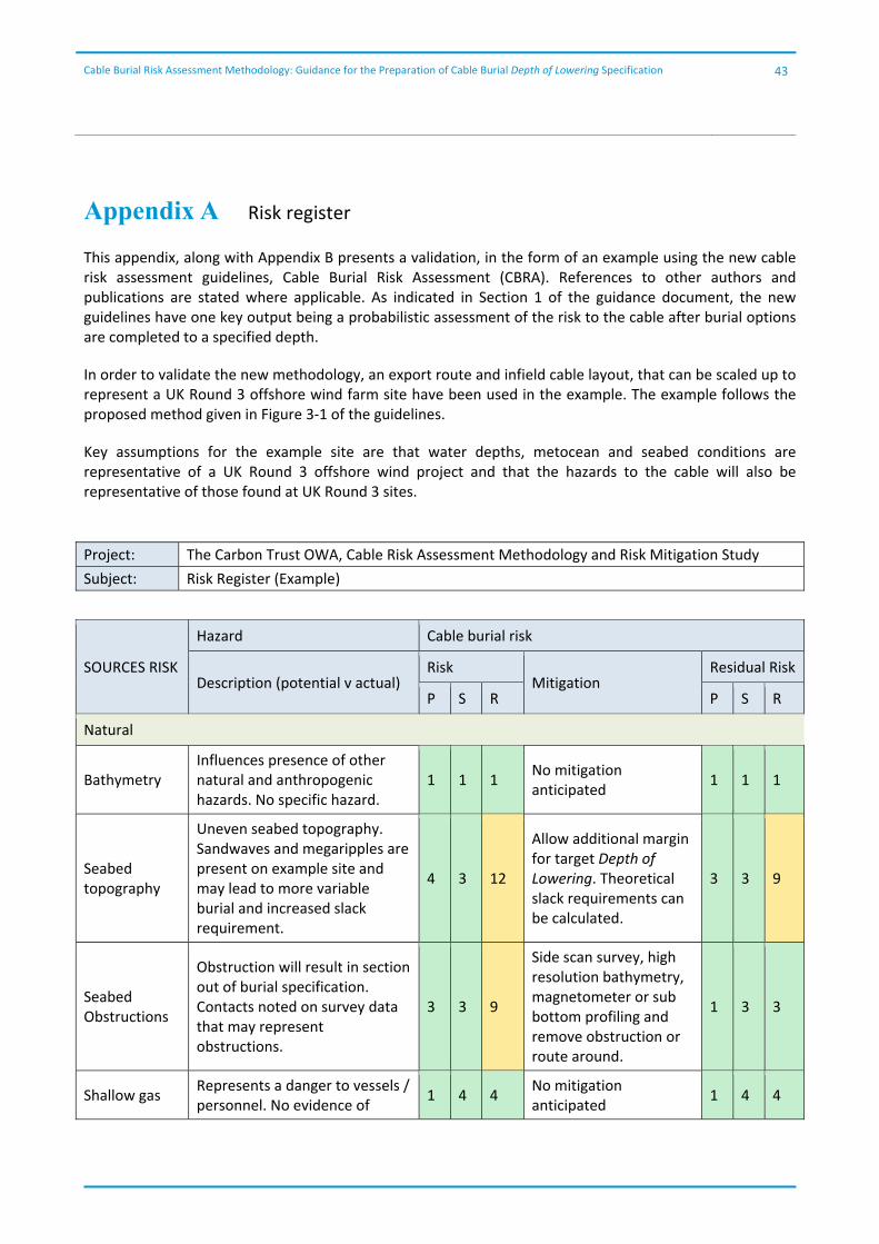
Cable Burial Risk Assessment Methodology: Guidance for the Preparation of Cable Burial Depth of Lowering Specification
43
Appendix A Risk register
This appendix, along with Appendix B presents a validation, in the form of an example using the new cable risk assessment guidelines, Cable Burial Risk Assessment (CBRA). References to other authors and publications are stated where applicable. As indicated in Section 1 of the guidance document, the new guidelines have one key output being a probabilistic assessment of the risk to the cable after burial options are completed to a specified depth.
In order to validate the new methodology, an export route and infield cable layout, that can be scaled up to represent a UK Round 3 offshore wind farm site have been used in the example. The example follows the proposed method given in Figure 3‐1 of the guidelines.
Key assumptions for the example site are that water depths, metocean and seabed conditions are representative of a UK Round 3 offshore wind project and that the hazards to the cable will also be representative of those found at UK Round 3 sites.
Project: The Carbon Trust OWA, Cable Risk Assessment Methodology and Risk Mitigation Study
Subject: Risk Register (Example)
SOURCES RISK
Hazard Cable burial risk
Description (potential v actual) Risk
Mitigation Residual Risk
P S R P S R
Natural
Bathymetry Influences presence of other natural and anthropogenic hazards. No specific hazard.
1 1 1 No mitigation anticipated
1 1 1
Seabed topography
Uneven seabed topography. Sandwaves and megaripples are present on example site and may lead to more variable burial and increased slack requirement.
4 3 12
Allow additional margin for target Depth of Lowering. Theoretical slack requirements can be calculated.
3 3 9
Seabed Obstructions
Obstruction will result in section out of burial specification. Contacts noted on survey data that may represent obstructions.
3 3 9
Side scan survey, high resolution bathymetry, magnetometer or sub bottom profiling and remove obstruction or route around.
1 3 3
Shallow gas Represents a danger to vessels / personnel. No evidence of
1 4 4 No mitigation anticipated
1 4 4

Cable Burial Risk Assessment Methodology: Guidance for the Preparation of Cable Burial Depth of Lowering Specification
44
SOURCES RISK
Hazard Cable burial risk
Description (potential v actual) Risk
Mitigation Residual Risk
P S R P S R
shallow gas on survey data.
Currents / waves
Abrasion, stress and fatigue where cables cross rock/rough terrain. Can induce loading on cable connectors. Can mobilise sediment exposing cables to further primary hazards. Metocean conditions likely to impact on surface laid cable and also influence sediment mobility.
3 3 9
Adequate burial, remedial protective measures or cable pinning to prevent movement.
2 2 4
Density / turbidity currents
These may result from a number of phenomena and can travel at speed over great distances to significant depths. Can cause tensional breaks, abrasions or may bury cables. Not anticipated at example site.
1 3 3 No mitigation required 1 3 3
Fish Bites
Can damage insulation; historically mainly occurred with telegraph cables but recent occurrences have been noted occasionally. Considered unlikely at example site.
1 3 3 No mitigation required 1 3 3
Extreme Weather
An increase in current and wave strength, can increase sediment input and bury cables deeper than designed. Metocean conditions modelled for design life of project.
1 4 4 No mitigation required 1 4 4
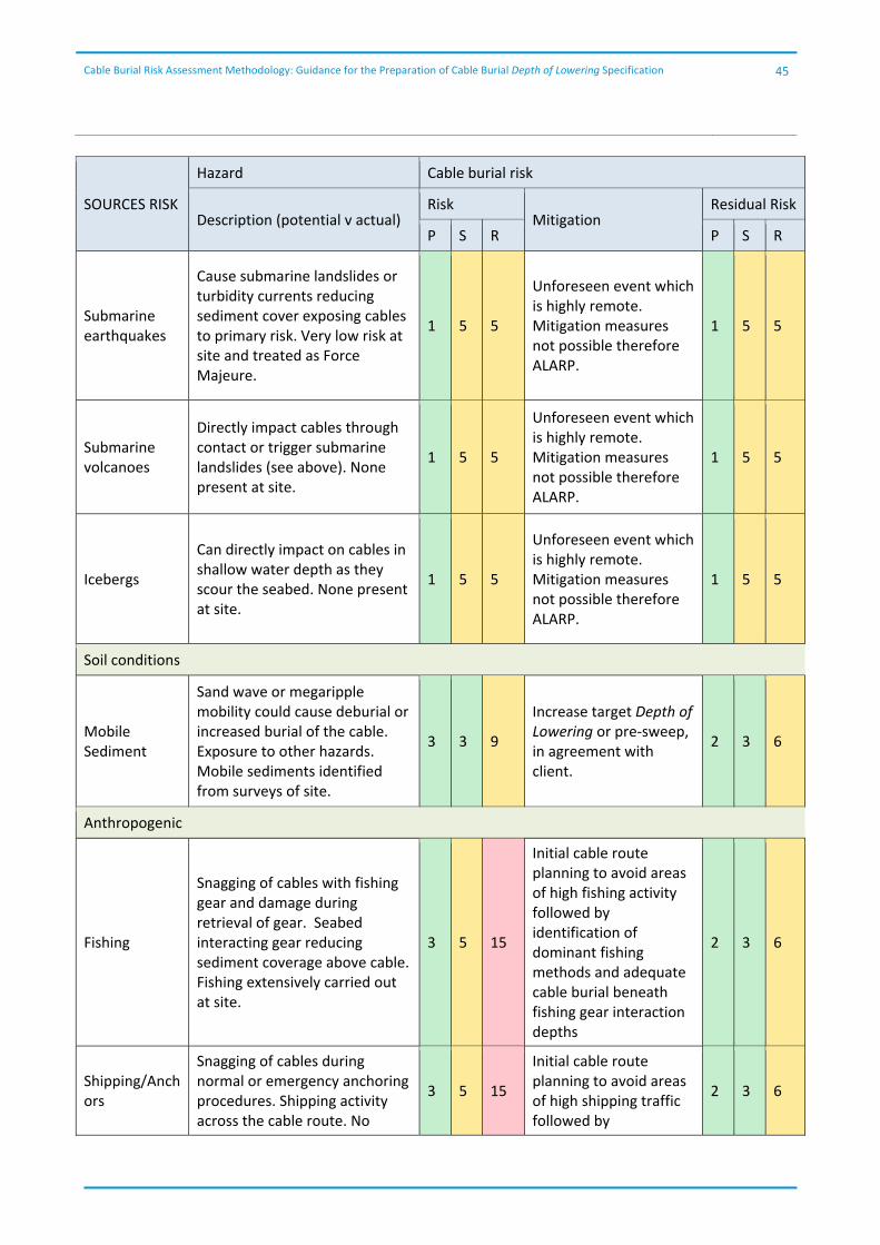
Cable Burial Risk Assessment Methodology: Guidance for the Preparation of Cable Burial Depth of Lowering Specification
45
SOURCES RISK
Hazard Cable burial risk
Description (potential v actual) Risk
Mitigation Residual Risk
P S R P S R
Submarine earthquakes
Cause submarine landslides or turbidity currents reducing sediment cover exposing cables to primary risk. Very low risk at site and treated as Force Majeure.
1 5 5
Unforeseen event which is highly remote. Mitigation measures not possible therefore ALARP.
1 5 5
Submarine volcanoes
Directly impact cables through contact or trigger submarine landslides (see above). None present at site.
1 5 5
Unforeseen event which is highly remote. Mitigation measures not possible therefore ALARP.
1 5 5
Icebergs
Can directly impact on cables in shallow water depth as they scour the seabed. None present at site.
1 5 5
Unforeseen event which is highly remote. Mitigation measures not possible therefore ALARP.
1 5 5
Soil conditions
Mobile Sediment
Sand wave or megaripple mobility could cause deburial or increased burial of the cable. Exposure to other hazards. Mobile sediments identified from surveys of site.
3 3 9
Increase target Depth of Lowering or pre‐sweep, in agreement with client.
2 3 6
Anthropogenic
Fishing
Snagging of cables with fishing gear and damage during retrieval of gear. Seabed interacting gear reducing sediment coverage above cable. Fishing extensively carried out at site.
3 5 15
Initial cable route planning to avoid areas of high fishing activity followed by identification of dominant fishing methods and adequate cable burial beneath fishing gear interaction depths
2 3 6
Shipping/Anchors
Snagging of cables during normal or emergency anchoring procedures. Shipping activity across the cable route. No
3 5 15
Initial cable route planning to avoid areas of high shipping traffic followed by
2 3 6
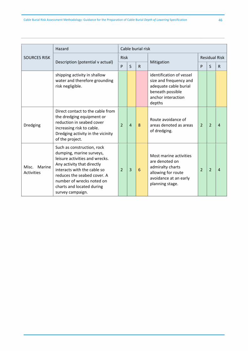
Cable Burial Risk Assessment Methodology: Guidance for the Preparation of Cable Burial Depth of Lowering Specification
46
SOURCES RISK
Hazard Cable burial risk
Description (potential v actual) Risk
Mitigation Residual Risk
P S R P S R
shipping activity in shallow water and therefore grounding risk negligible.
identification of vessel size and frequency and adequate cable burial beneath possible anchor interaction depths
Dredging
Direct contact to the cable from the dredging equipment or reduction in seabed cover increasing risk to cable. Dredging activity in the vicinity of the project.
2 4 8 Route avoidance of areas denoted as areas of dredging.
2 2 4
Misc. Marine Activities
Such as construction, rock dumping, marine surveys, leisure activities and wrecks. Any activity that directly interacts with the cable so reduces the seabed cover. A number of wrecks noted on charts and located during survey campaign.
2 3 6
Most marine activities are denoted on admiralty charts allowing for route avoidance at an early planning stage.
2 2 4

Cable Burial Risk Assessment Methodology: Guidance for the Preparation of Cable Burial Depth of Lowering Specification
47
Appendix B Worked CBRA example
This Appendix, along with Appendix A presents a validation in the form of an example using the new cable risk assessment guidelines, Cable Burial Risk Assessment (CBRA). The example follows the proposed method given in Figure 3‐1 of the new guidelines.
Key elements of the idealised export and infield cable routes are water depth, seabed profile, geology and seabed features and hazard type and distribution. The hazard type and distribution has been determined in the risk register presented in Appendix A.
Cable Routeing – Section 4
For the CBRA example, it is assumed that cable routeing has been undertaken as part of the planning process and that those hazards that can be avoided by routeing, for example, dredging areas or ships anchor zones have been avoided.
Collation of Data and Suitability Review – Section 5
Appropriate survey data has been collected, relevant to the planned development, site / route conditions and installation techniques.
Assessment of Seabed Conditions – Section 6
Seabed conditions for an export route and infield cable arrays are presented in Figure B. 1 and Figure B. 2 below. The water depth and seabed conditions are considered typical of a UK Round 3 Offshore Wind Farm with variable water depths from 0 m (landfall) to >50 m and seabed geology which in turn will result in a variable hazard distribution and depth of interaction.
Figure B. 1 Export Route
Seabed conditions were selected to demonstrate the use of burial to protect against a range of hazards. However, there are certain conditions, for example rock at shallow depth, where alternative protection methods would need to be considered/adopted. The presence of layered or mixed sediments also represent complex conditions that require site specific assessment and engineering judgement.
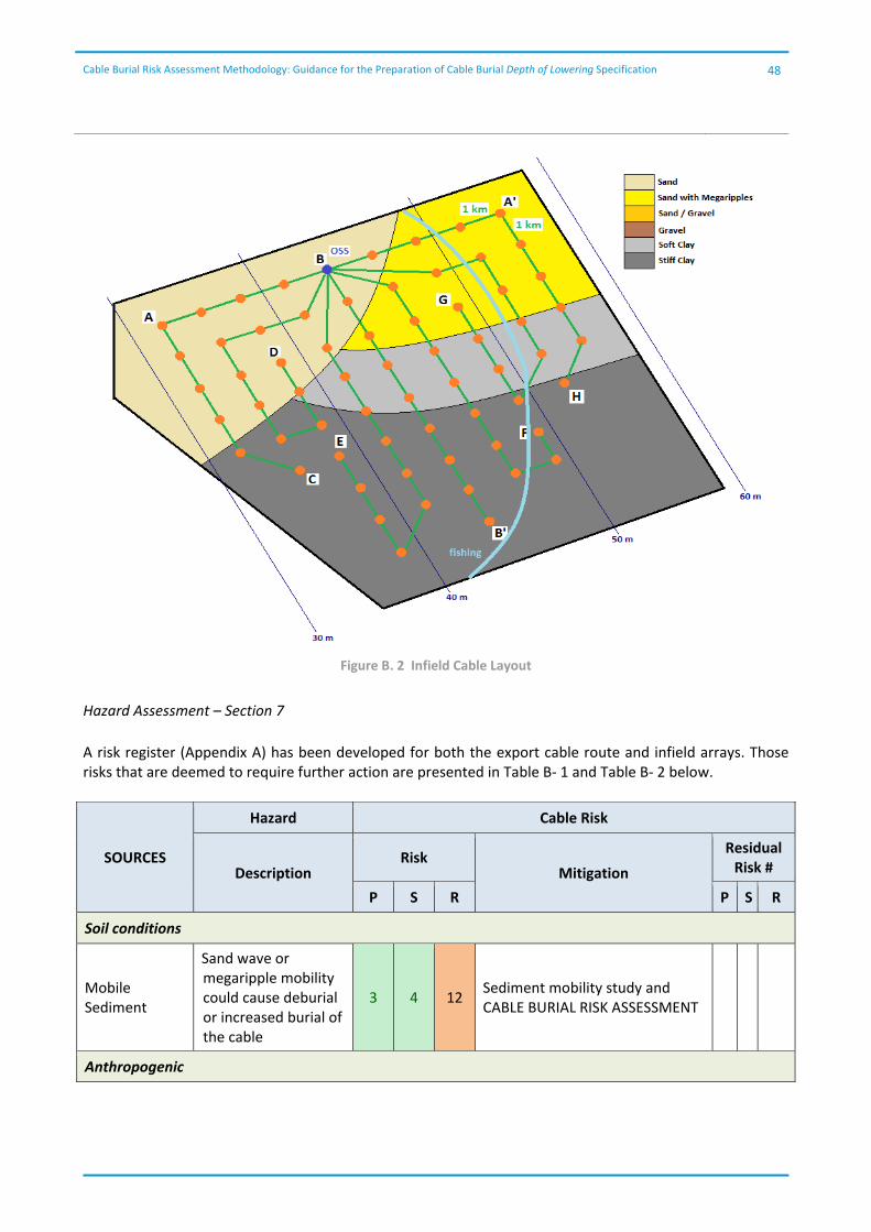
Cable Burial Risk Assessment Methodology: Guidance for the Preparation of Cable Burial Depth of Lowering Specification
48
Figure B. 2 Infield Cable Layout
Hazard Assessment – Section 7
A risk register (Appendix A) has been developed for both the export cable route and infield arrays. Those risks that are deemed to require further action are presented in Table B‐ 1 and Table B‐ 2 below.
SOURCES
Hazard Cable Risk
Description Risk
Mitigation
Residual Risk #
P S R P S R
Soil conditions
Mobile Sediment
Sand wave or megaripple mobility could cause deburial or increased burial of the cable
3 4 12 Sediment mobility study and CABLE BURIAL RISK ASSESSMENT
Anthropogenic
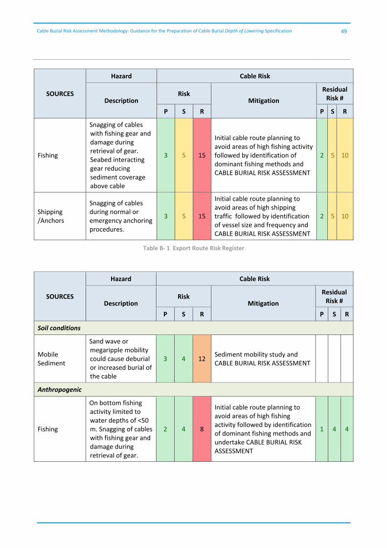
Cable Burial Risk Assessment Methodology: Guidance for the Preparation of Cable Burial Depth of Lowering Specification
49
SOURCES
Hazard Cable Risk
Description Risk
Mitigation
Residual Risk #
P S R P S R
Fishing
Snagging of cables with fishing gear and damage during retrieval of gear. Seabed interacting gear reducing sediment coverage above cable
3 5 15
Initial cable route planning to avoid areas of high fishing activity followed by identification of dominant fishing methods and CABLE BURIAL RISK ASSESSMENT
2 5 10
Shipping /Anchors
Snagging of cables during normal or emergency anchoring procedures.
3 5 15
Initial cable route planning to avoid areas of high shipping traffic followed by identification of vessel size and frequency and CABLE BURIAL RISK ASSESSMENT
2 5 10
Table B‐ 1 Export Route Risk Register
SOURCES
Hazard Cable Risk
Description Risk
Mitigation
Residual Risk #
P S R P S R
Soil conditions
Mobile Sediment
Sand wave or megaripple mobility could cause deburial or increased burial of the cable
3 4 12 Sediment mobility study and CABLE BURIAL RISK ASSESSMENT
Anthropogenic
Fishing
On bottom fishing activity limited to water depths of <50 m. Snagging of cables with fishing gear and damage during retrieval of gear.
2 4 8
Initial cable route planning to avoid areas of high fishing activity followed by identification of dominant fishing methods and undertake CABLE BURIAL RISK ASSESSMENT
1 4 4
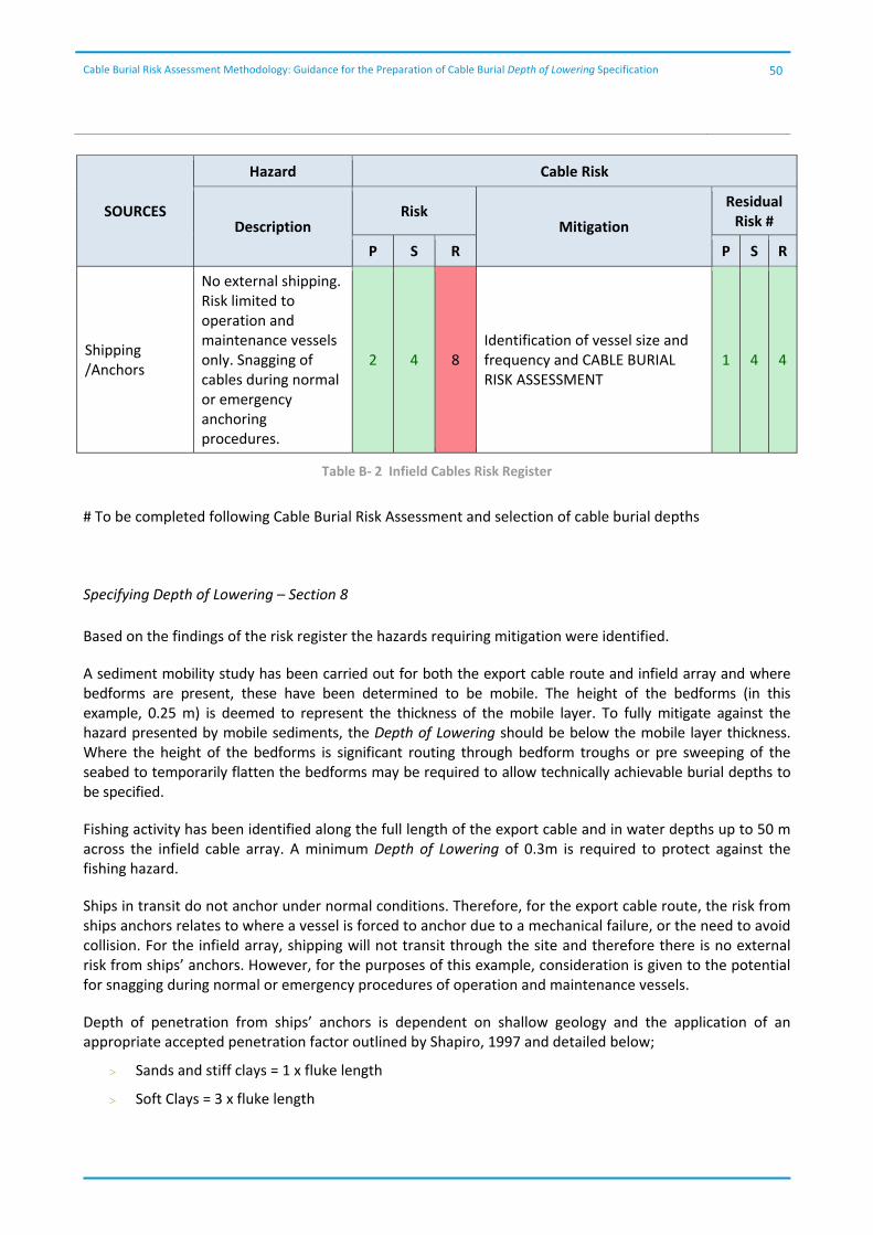
Cable Burial Risk Assessment Methodology: Guidance for the Preparation of Cable Burial Depth of Lowering Specification
50
SOURCES
Hazard Cable Risk
Description Risk
Mitigation
Residual Risk #
P S R P S R
Shipping /Anchors
No external shipping. Risk limited to operation and maintenance vessels only. Snagging of cables during normal or emergency anchoring procedures.
2 4 8 Identification of vessel size and frequency and CABLE BURIAL RISK ASSESSMENT
1 4 4
Table B‐ 2 Infield Cables Risk Register
# To be completed following Cable Burial Risk Assessment and selection of cable burial depths
Specifying Depth of Lowering – Section 8
Based on the findings of the risk register the hazards requiring mitigation were identified.
A sediment mobility study has been carried out for both the export cable route and infield array and where bedforms are present, these have been determined to be mobile. The height of the bedforms (in this example, 0.25 m) is deemed to represent the thickness of the mobile layer. To fully mitigate against the hazard presented by mobile sediments, the Depth of Lowering should be below the mobile layer thickness. Where the height of the bedforms is significant routing through bedform troughs or pre sweeping of the seabed to temporarily flatten the bedforms may be required to allow technically achievable burial depths to be specified.
Fishing activity has been identified along the full length of the export cable and in water depths up to 50 m across the infield cable array. A minimum Depth of Lowering of 0.3m is required to protect against the fishing hazard.
Ships in transit do not anchor under normal conditions. Therefore, for the export cable route, the risk from ships anchors relates to where a vessel is forced to anchor due to a mechanical failure, or the need to avoid collision. For the infield array, shipping will not transit through the site and therefore there is no external risk from ships’ anchors. However, for the purposes of this example, consideration is given to the potential for snagging during normal or emergency procedures of operation and maintenance vessels.
Depth of penetration from ships’ anchors is dependent on shallow geology and the application of an appropriate accepted penetration factor outlined by Shapiro, 1997 and detailed below;
Sands and stiff clays = 1 x fluke length
Soft Clays = 3 x fluke length
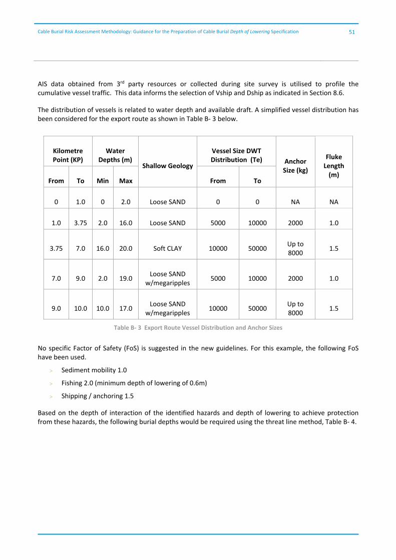
Cable Burial Risk Assessment Methodology: Guidance for the Preparation of Cable Burial Depth of Lowering Specification
51
AIS data obtained from 3rd party resources or collected during site survey is utilised to profile the cumulative vessel traffic. This data informs the selection of Vship and Dship as indicated in Section 8.6.
The distribution of vessels is related to water depth and available draft. A simplified vessel distribution has been considered for the export route as shown in Table B‐ 3 below.
Kilometre Point (KP)
Water Depths (m)
Shallow Geology
Vessel Size DWT Distribution (Te) Anchor
Size (kg)
Fluke Length (m)
From To Min Max From To
0 1.0 0 2.0 Loose SAND 0 0 NA NA
1.0 3.75 2.0 16.0 Loose SAND 5000 10000 2000 1.0
3.75 7.0 16.0 20.0 Soft CLAY 10000 50000 Up to 8000
1.5
7.0 9.0 2.0 19.0 Loose SAND
w/megaripples 5000 10000 2000 1.0
9.0 10.0 10.0 17.0 Loose SAND
w/megaripples 10000 50000
Up to 8000
1.5
Table B‐ 3 Export Route Vessel Distribution and Anchor Sizes
No specific Factor of Safety (FoS) is suggested in the new guidelines. For this example, the following FoS have been used.
Sediment mobility 1.0
Fishing 2.0 (minimum depth of lowering of 0.6m)
Shipping / anchoring 1.5
Based on the depth of interaction of the identified hazards and depth of lowering to achieve protection from these hazards, the following burial depths would be required using the threat line method, Table B‐ 4.
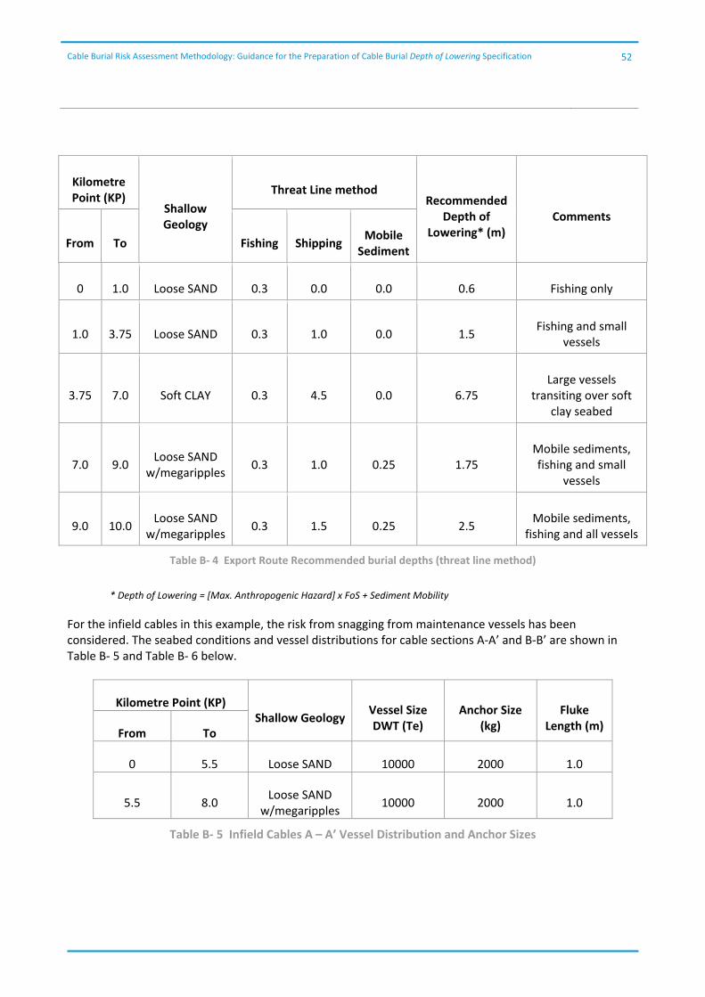
Cable Burial Risk Assessment Methodology: Guidance for the Preparation of Cable Burial Depth of Lowering Specification
52
Kilometre Point (KP)
Shallow Geology
Threat Line method Recommended
Depth of Lowering* (m)
Comments
From To Fishing Shipping Mobile
Sediment
0 1.0 Loose SAND 0.3 0.0 0.0 0.6 Fishing only
1.0 3.75 Loose SAND 0.3 1.0 0.0 1.5 Fishing and small
vessels
3.75 7.0 Soft CLAY 0.3 4.5 0.0 6.75 Large vessels
transiting over soft clay seabed
7.0 9.0 Loose SAND
w/megaripples 0.3 1.0 0.25 1.75
Mobile sediments, fishing and small
vessels
9.0 10.0 Loose SAND
w/megaripples 0.3 1.5 0.25 2.5
Mobile sediments, fishing and all vessels
Table B‐ 4 Export Route Recommended burial depths (threat line method)
* Depth of Lowering = [Max. Anthropogenic Hazard] x FoS + Sediment Mobility
For the infield cables in this example, the risk from snagging from maintenance vessels has been considered. The seabed conditions and vessel distributions for cable sections A‐A’ and B‐B’ are shown in Table B‐ 5 and Table B‐ 6 below.
Kilometre Point (KP) Shallow Geology
Vessel Size DWT (Te)
Anchor Size (kg)
Fluke Length (m)
From To
0 5.5 Loose SAND 10000 2000 1.0
5.5 8.0 Loose SAND
w/megaripples 10000 2000 1.0
Table B‐ 5 Infield Cables A – A’ Vessel Distribution and Anchor Sizes
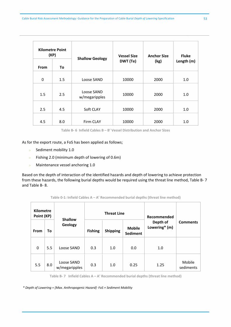
Cable Burial Risk Assessment Methodology: Guidance for the Preparation of Cable Burial Depth of Lowering Specification
53
Kilometre Point (KP)
Shallow Geology Vessel Size DWT (Te)
Anchor Size (kg)
Fluke Length (m)
From To
0 1.5 Loose SAND 10000 2000 1.0
1.5 2.5 Loose SAND
w/megaripples 10000 2000 1.0
2.5 4.5 Soft CLAY 10000 2000 1.0
4.5 8.0 Firm CLAY 10000 2000 1.0
Table B‐ 6 Infield Cables B – B’ Vessel Distribution and Anchor Sizes
As for the export route, a FoS has been applied as follows;
Sediment mobility 1.0
Fishing 2.0 (minimum depth of lowering of 0.6m)
Maintenance vessel anchoring 1.0
Based on the depth of interaction of the identified hazards and depth of lowering to achieve protection from these hazards, the following burial depths would be required using the threat line method, Table B‐ 7 and Table B‐ 8.
Table 0‐1: Infield Cables A – A’ Recommended burial depths (threat line method)
Kilometre Point (KP)
Shallow Geology
Threat Line Recommended
Depth of Lowering* (m)
Comments
From To Fishing Shipping Mobile
Sediment
0 5.5 Loose SAND 0.3 1.0 0.0 1.0
5.5 8.0 Loose SAND
w/megaripples 0.3 1.0 0.25 1.25
Mobile sediments
Table B‐ 7 Infield Cables A – A’ Recommended burial depths (threat line method)
* Depth of Lowering = [Max. Anthropogenic Hazard]∙ FoS + Sediment Mobility
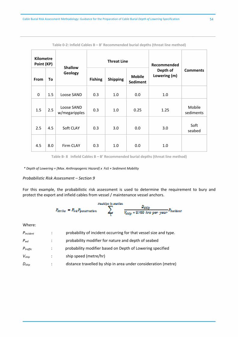
Cable Burial Risk Assessment Methodology: Guidance for the Preparation of Cable Burial Depth of Lowering Specification
54
Table 0‐2: Infield Cables B – B’ Recommended burial depths (threat line method)
Kilometre Point (KP)
Shallow Geology
Threat Line Recommended
Depth of Lowering (m)
Comments
From To Fishing Shipping Mobile
Sediment
0 1.5 Loose SAND 0.3 1.0 0.0 1.0
1.5 2.5 Loose SAND
w/megaripples 0.3 1.0 0.25 1.25
Mobile sediments
2.5 4.5 Soft CLAY 0.3 3.0 0.0 3.0 Soft
seabed
4.5 8.0 Firm CLAY 0.3 1.0 0.0 1.0
Table B‐ 8 Infield Cables B – B’ Recommended burial depths (threat line method)
* Depth of Lowering = [Max. Anthropogenic Hazard] x FoS + Sediment Mobility
Probabilistic Risk Assessment – Section 9
For this example, the probabilistic risk assessment is used to determine the requirement to bury and protect the export and infield cables from vessel / maintenance vessel anchors.
Where:
Pincident : probability of incident occurring for that vessel size and type.
Pwd : probability modifier for nature and depth of seabed
Ptraffic : probability modifier based on Depth of Lowering specified
Vship : ship speed (metre/hr)
Dship : distance travelled by ship in area under consideration (metre)
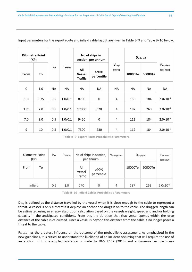
Cable Burial Risk Assessment Methodology: Guidance for the Preparation of Cable Burial Depth of Lowering Specification
55
Input parameters for the export route and infield cable layout are given in Table B‐ 9 and Table B‐ 10 below.
Kilometre Point (KP)
Pwd P traffic
No of ships in section, per annum
Vship
(knots)
Dship (m)
Pincident (per hour)
From To All
Vessel Traffic
>90% percentile
10000Te 50000Te
0 1.0 NA NA NA NA NA NA NA NA
1.0 3.75 0.5 1.0/0.1 8700 0 4 150 184 2.0x10‐5
3.75 7.0 0.5 1.0/0.1 12000 620 4 187 263 2.0x10‐5
7.0 9.0 0.5 1.0/0.1 9450 0 4 112 184 2.0x10‐5
9 10 0.5 1.0/0.1 7300 230 4 112 184 2.0x10‐5
Table B‐ 9 Export Route Probabilistic Parameters
Kilometre Point (KP)
Pwd P traffic No of ships in section, per annum
Vship (knots) Dship (m) Pincident (per hour)
From To All Vessel Traffic
>90% percentile
10000Te 50000Te
Infield 0.5 1.0 270 0 4 187 263 2.0x10‐5
Table B‐ 10 Infield Cables Probabilistic Parameters
Dship is defined as the distance travelled by the vessel when it is close enough to the cable to represent a threat. A vessel is only a threat if it deploys an anchor and drags it on to the cable. The dragged length can be estimated using an energy absorption calculation based on the vessels weight, speed and anchor holding capacity in the anticipated conditions. From this the duration that that vessel spends within the drag distance of the cable is calculated. Once a vessel is beyond this distance from the cable it no longer poses a threat to the cable.
Pincident has the greatest influence on the outcome of the probabilistic assessment. As emphasized in the new guidelines, it is critical to understand the likelihood of an incident occurring that will require the use of an anchor. In this example, reference is made to DNV F107 (2010) and a conservative machinery
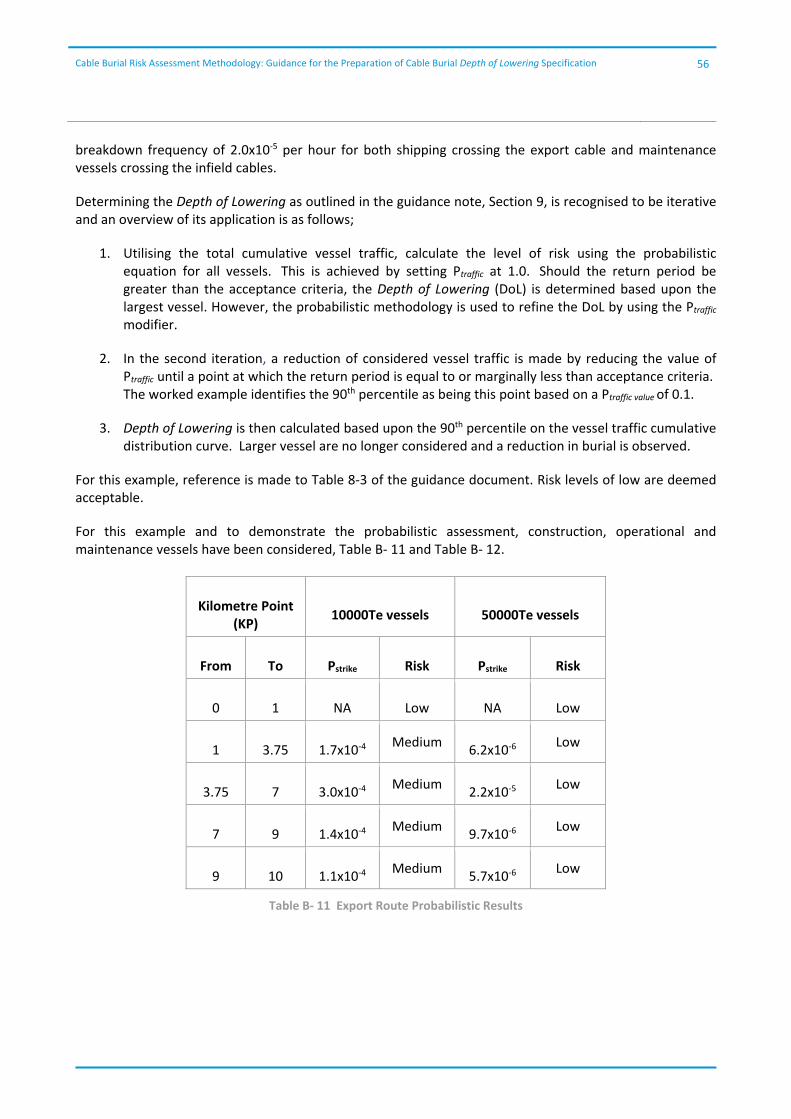
Cable Burial Risk Assessment Methodology: Guidance for the Preparation of Cable Burial Depth of Lowering Specification
56
breakdown frequency of 2.0x10‐5 per hour for both shipping crossing the export cable and maintenance vessels crossing the infield cables.
Determining the Depth of Lowering as outlined in the guidance note, Section 9, is recognised to be iterative and an overview of its application is as follows;
1. Utilising the total cumulative vessel traffic, calculate the level of risk using the probabilistic equation for all vessels. This is achieved by setting Ptraffic at 1.0. Should the return period be greater than the acceptance criteria, the Depth of Lowering (DoL) is determined based upon the largest vessel. However, the probabilistic methodology is used to refine the DoL by using the Ptraffic modifier.
2. In the second iteration, a reduction of considered vessel traffic is made by reducing the value of Ptraffic until a point at which the return period is equal to or marginally less than acceptance criteria. The worked example identifies the 90th percentile as being this point based on a Ptraffic value of 0.1.
3. Depth of Lowering is then calculated based upon the 90th percentile on the vessel traffic cumulative distribution curve. Larger vessel are no longer considered and a reduction in burial is observed.
For this example, reference is made to Table 8‐3 of the guidance document. Risk levels of low are deemed acceptable.
For this example and to demonstrate the probabilistic assessment, construction, operational and maintenance vessels have been considered, Table B‐ 11 and Table B‐ 12.
Kilometre Point (KP)
10000Te vessels 50000Te vessels
From To Pstrike Risk Pstrike Risk
0 1 NA Low NA Low
1 3.75 1.7x10‐4 Medium
6.2x10‐6 Low
3.75 7 3.0x10‐4 Medium
2.2x10‐5 Low
7 9 1.4x10‐4 Medium
9.7x10‐6 Low
9 10 1.1x10‐4 Medium
5.7x10‐6 Low
Table B‐ 11 Export Route Probabilistic Results
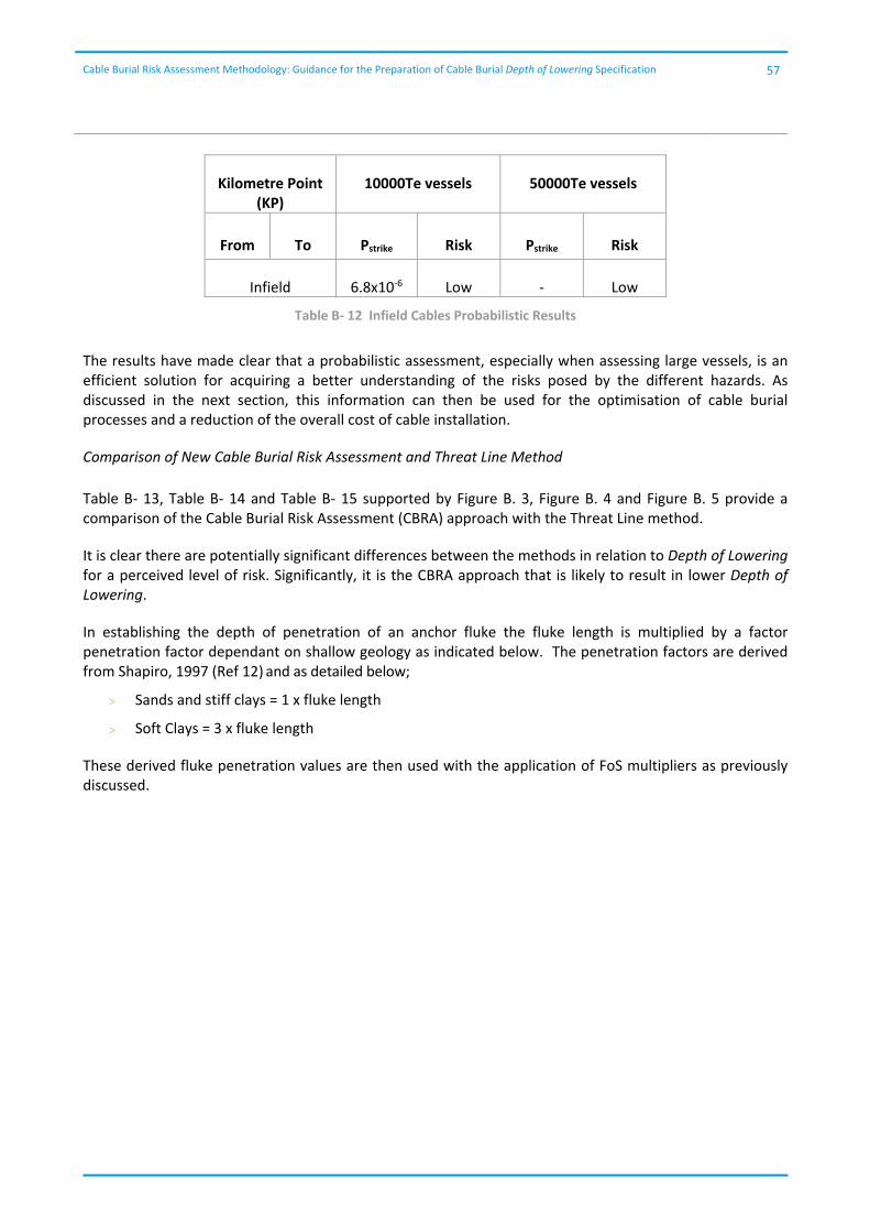
Cable Burial Risk Assessment Methodology: Guidance for the Preparation of Cable Burial Depth of Lowering Specification
57
Kilometre Point (KP)
10000Te vessels 50000Te vessels
From To Pstrike Risk Pstrike Risk
Infield 6.8x10‐6 Low ‐ Low
Table B‐ 12 Infield Cables Probabilistic Results
The results have made clear that a probabilistic assessment, especially when assessing large vessels, is an efficient solution for acquiring a better understanding of the risks posed by the different hazards. As discussed in the next section, this information can then be used for the optimisation of cable burial processes and a reduction of the overall cost of cable installation.
Comparison of New Cable Burial Risk Assessment and Threat Line Method
Table B‐ 13, Table B‐ 14 and Table B‐ 15 supported by Figure B. 3, Figure B. 4 and Figure B. 5 provide a comparison of the Cable Burial Risk Assessment (CBRA) approach with the Threat Line method.
It is clear there are potentially significant differences between the methods in relation to Depth of Lowering for a perceived level of risk. Significantly, it is the CBRA approach that is likely to result in lower Depth of Lowering.
In establishing the depth of penetration of an anchor fluke the fluke length is multiplied by a factor penetration factor dependant on shallow geology as indicated below. The penetration factors are derived from Shapiro, 1997 (Ref 12) and as detailed below;
Sands and stiff clays = 1 x fluke length
Soft Clays = 3 x fluke length
These derived fluke penetration values are then used with the application of FoS multipliers as previously discussed.
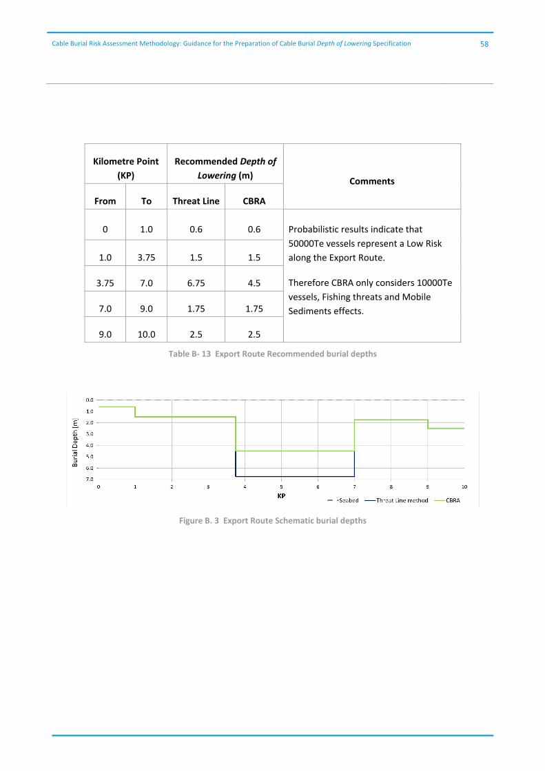
Cable Burial Risk Assessment Methodology: Guidance for the Preparation of Cable Burial Depth of Lowering Specification
58
Kilometre Point
(KP)
Recommended Depth of
Lowering (m) Comments
From To Threat Line CBRA
0 1.0 0.6 0.6 Probabilistic results indicate that
50000Te vessels represent a Low Risk
along the Export Route.
Therefore CBRA only considers 10000Te
vessels, Fishing threats and Mobile
Sediments effects.
1.0 3.75 1.5 1.5
3.75 7.0 6.75 4.5
7.0 9.0 1.75 1.75
9.0 10.0 2.5 2.5
Table B‐ 13 Export Route Recommended burial depths
Figure B. 3 Export Route Schematic burial depths
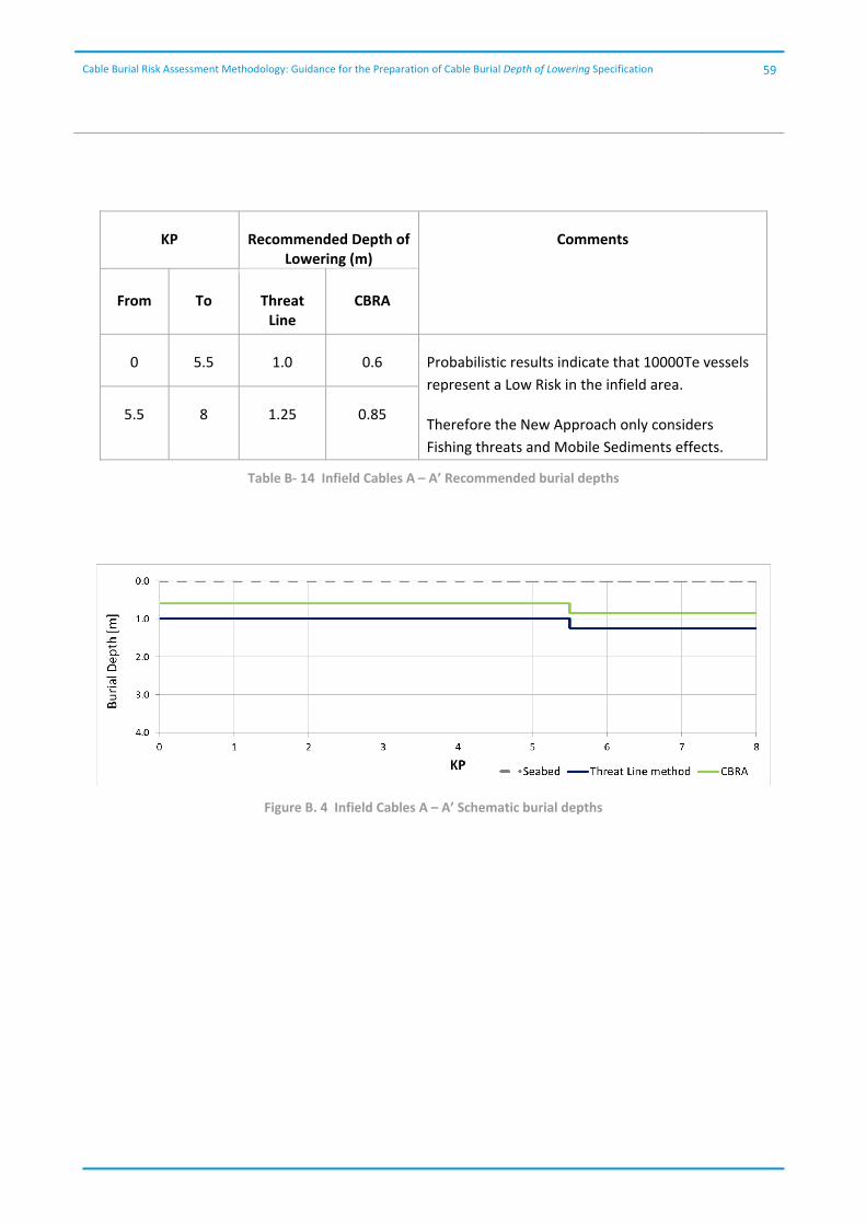
Cable Burial Risk Assessment Methodology: Guidance for the Preparation of Cable Burial Depth of Lowering Specification
59
KP Recommended Depth of Lowering (m)
Comments
From To Threat Line
CBRA
0 5.5 1.0 0.6 Probabilistic results indicate that 10000Te vessels
represent a Low Risk in the infield area.
Therefore the New Approach only considers
Fishing threats and Mobile Sediments effects.
5.5 8 1.25 0.85
Table B‐ 14 Infield Cables A – A’ Recommended burial depths
Figure B. 4 Infield Cables A – A’ Schematic burial depths
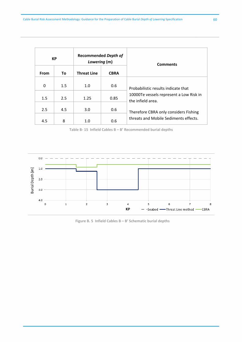
Cable Burial Risk Assessment Methodology: Guidance for the Preparation of Cable Burial Depth of Lowering Specification
60
KP Recommended Depth of
Lowering (m) Comments
From To Threat Line CBRA
0 1.5 1.0 0.6 Probabilistic results indicate that
10000Te vessels represent a Low Risk in
the infield area.
Therefore CBRA only considers Fishing
threats and Mobile Sediments effects.
1.5 2.5 1.25 0.85
2.5 4.5 3.0 0.6
4.5 8 1.0 0.6
Table B‐ 15 Infield Cables B – B’ Recommended burial depths
Figure B. 5 Infield Cables B – B’ Schematic burial depths

Cable Burial Risk Assessment Methodology: Guidance for the Preparation of Cable Burial Depth of Lowering Specification
61
Conclusions
The validation of the Cable Burial Risk Assessment (CBRA) has made clear that a probabilistic assessment of the risk optimises the burial process and provides greater assurance to developers, insurers, cable installer and the industry as a whole, as well as potentially reducing the overall cost of cable installation. Hence, it is anticipated that where stakeholders and consenting bodies have requested significant burial depths on existing wind farms due to a perceived threat, the probabilistic method shown here can be used to support the safe reduction of specified depths based on actual site conditions.
When comparing the Threat Line method vs CBRA it is noted that;
The most significant reductions in required burial given by the CBRA were observed in this instance when assessing large vessels. Protection from all anchors that might cross the route is not realistic and a probabilistic method is hence needed
The CBRA method is more reliant on quality and specific nature of shipping data. To perform a probabilistic assessment the density and frequency of vessels as well as the specific vessel details (or if not available dead weight tonnage) is required
The methods are comparative in regards to fishing.
Several additional considerations are summarised as follows:
1. The developed guidance considers only the burial depth required to protect the cable from external threats. Requirements specified for environmental reasons, or for operational/construction reasons are not considered.
2. Survey data, shipping Information and fishing studies are usually acquired in the early stages of conceptual design and for the preparation of environmental statements. The final cable routeing will be rarely along the original design route.
3. When taking into account the Probability of an Anchor Striking the cable (probabilistic approach), it is essential to understand the scale of the residual risk to the cable; i.e. what is the residual risk posed by the 10% of larger vessels (assuming the 90th percentile was selected).
4. When undertaking the Risk Assessment an objective evaluation of 'Risk' should be presented, in which assumptions and uncertainties are clearly considered. When assessing the potential loss and probability of occurrence, the measuring these two concepts can be difficult. Therefore taking into account the criteria of assessing risks within this document. A practical approach to assessment shall be adopted based on known site conditions, together with statistical historical and current data being taken into account.
5. A clear distinction should be made when assessing the risks, between that of Export and Array Cabling. Any assessment should separately consider Export Cables and Array Cables due to the changes in shipping before and after construction.
The Carbon Trust is an independent company with a mission to accelerate the move to a sustainable, low carbon economy.
We advise businesses, governments and the public sector on their opportunities in a sustainable low‐carbon world
We measure and certify the environmental footprint of organisations, products and services
We help develop and deploy low‐carbon technologies and solutions, from energy efficiency to renewable power
Acknowledgements
The OWA wishes to thank all the contributors who actively participated in the development of the methodology guidelines with special acknowledgements to the following members of the Consortium of Consultants: Scott Gooding (UTEC Geomarine), Paul Errington (Cathie Associates) and James Hunt (Xodus Group). Further special acknowledgement is given to the all the members of the Cable Installation Technical Working Group of the OWA and to all the employees of the OWA partners that have reviewed the document. In addition, the OWA would like to thank Mr. Claus F. Christensen who initially developed and presented the first version of this methodology back in 2006. Finally the OWA would like to thank Mr. Jeremy Featherstone and all the parties from the industry that have provided invaluable feedback on this guidance document namely 4C Offshore, ABS group, Codan, Deepocean, DNV‐GL, Helix offshore, Intertek, Reef subsea, SIEM Offshore, Subsea 7, Tideway, Van Oord, VBMS.
www.carbontrust.com
+44 20 7170 7000
CTC835
Whilst reasonable steps have been taken to ensure that the information contained within this publication is correct, the authors, the Carbon Trust, its agents, contractors and sub‐contractors give no warranty and make no representation as to its accuracy and accept no liability for any errors or omissions. Any trademarks, service marks or logos used in this publication, and copyright in it, are the property of the Carbon Trust. Nothing in this publication shall be construed as granting any licence or right to use or reproduce any of the trademarks, service marks, logos, copyright or any proprietary information in any way without the Carbon Trust’s prior written permission. The Carbon Trust enforces infringements of its intellectual property rights to the full extent permitted by law. The Carbon Trust is a company limited by guarantee and registered in England and Wales under Company number 4190230 with its Registered Office at: 4th Floor, Dorset House, 27‐45 Stamford Street, London SE1 9NT
Published in the UK: February 2015.
© The Carbon Trust 2015. All rights reserved.