Embed Size (px)
Citation preview

Distribution Statement “A”
GUIDANCE INTEGRATED FUZE DEMONSTRATION PROGRAM
Presented By: Wayne Worrell GIF Project Manager
Naval Surface Warfare Center, Dahlgren Division Precision and Advanced Systems Branch, G33
540-653-6025, [email protected]
Distribution Statement A: Approved for Public Release; Distribution is Unlimited.

Distribution Statement “A”
22
BACKGROUND• The Guidance Integrated Fuze "GIF" program is in its last year
of Demonstration Development.
• The Naval Surface Warfare Center was given two tasks:– Produce a self contained NATO standard fuze with
integrated guidance to increase the accuracy of existing gun projectile inventories.
– Produce a SAASM P(Y) GPS receiver with reduced cost/power requirements and sized to fit within a NATO standard fuze contour.
• This presentation will review fuze subsystems developed during the “GIF” program, final system test results, and the development of the 40mm SAASM GPS receiver and “VIPER” fuze.

Distribution Statement “A”
33
GIF - Major Component Development
Roll Brake
CR2 Battery Cells Power Fuze
Waffle Canards
HOB Sensor & Setter Coil
GPS Antennas
Guidance Electronic Unit - GEUCanard Actuation System

Distribution Statement “A”
44
Guidance Electronic Unit - GEU
J0008-E0024 & E0025 Semi-Conductor Bridge (SCB) Interface
Height Of Burst (HOB) Interface
Pad ConnectionsTest
Connector
J0008-E0017 Motor Connector
J0008-E0021 TM Power Connector
U.FL-2LP-068N1-A(50) Cable Assembly UFL
• Developed by Syntronics, Inc. for use in the GuidanceIntegrated Fuze “GIF”.
• The GEU successfully controlled: gun fire sensing, boot up,GPS receiver function, guidance computations, powerregulation, roll brake control, canard deployment and control,HOB sensor control, fire pulse generation, and telemetrymodulation data.

Distribution Statement “A”
55
Waffle CANARD
• Waffle canards were modeled, designed, analyzed, and wind tunnel tested by NSWCDD for our GIF fuze.
• Design gives more lift and less stalling than solidcontrol surfaces of similar size.
• Design easily conforms to the fuze contour and required less hinge moments to deflect and hold canards.

Distribution Statement “A”
66
CANARD ACTUATION SYSTEM
Page 1
GIF-12 76mm Gun Test OBR Data
-10000
-8000
-6000
-4000
-2000
0
2000
4000
6000
8000
10000
0 0.01 0.02 0.03 0.04 0.05 0.06 0.07 0.08 0.09 0.1
Time
Acc
eler
atio
n
Lateral #1 G's Calibrated
Lateral #2 G's Calibrated
Axial G's Calibrated
30 per. Mov. Avg. (Axial G's Calibrated)
• A motor driven gear train was developed by CAES Corp.
• The CAS performed robustly. One system was tested fivetimes to the gun G levels inthe graph to the left and continued to perform without degradation.

Distribution Statement “A”
77
• Small aperture GPS antennas were developed to fit withinNATO Standard Fuze dimensions by TOYON Research Corp.
• GIF uses two element active antennas.
• Four element linear and RHCP antennas were also developed.
GPS ANTENNAS

Distribution Statement “A”
88
TOYON Antenna Design Passive Four Element
90o
.572
Tapered Profile Formed by:• Bottom Radius – 1.208”• Top Radius – 1.039”• Thickness - .203”• Axial Height – 1”• Arc Width – 50o
Base of antenna sits .25” above the fuze shoulder.
50o
0.906”
1.054”
1”

Distribution Statement “A”
99
ROLL BRAKE
Roll Brake Torque (oz-in)
-8
-6
-4
-2
0
2
4
6
8
10
12
14
16
18
20
22
24
26
28
30
0 2 4 6 8 10 12 14 16 18 20 22 24 26 28 30 32 34 36 38 40 42 44 46 48 50 52 54 56 58 60
Torque30 per. Mov. Avg. (Torque)
• Designed & produced by CAES Corp.
• The fuze is decoupled from the projectile body and a constantroll is induced in the oppositespin direction of the projectile.
• The roll brake is used to couplethe fuze back to the projectile body by modulating the brake tohold the nose steady.

Distribution Statement “A”
1010
CR2 BATTERY POWER
• Used commercial off the shelf batteries.• G switch activated and used to power all fuze
functions. • The batteries survive gun shock.• Artificial aging tests predicted a minimum shelf
life of 7 years.

Distribution Statement “A”
1111
• Repackaged the MOFA signal processor into a single 1.075” diameter board solution.
• Coil form was shortened and coil modified to work with the EPIAFS setter.
• The standard MOFA antenna and MMIC was used.
Height of Burst & Inductive Set Repackaging
HOB Sensor & Inductive Set

Distribution Statement “A”
1212
Electronic Test Fuze (ETF)
IR Link
FPGA BoardFPGA BoardFPGA I/OFPGA I/OSensor BoardSensor BoardPower BoardPower BoardBatteriesBatteries

Distribution Statement “A”
1313
Telemetry Projectiles
M795 TM Projectile
• M 795
• M483
• M549 RAP

Distribution Statement “A”
1414
GIFFLIGHT PERFORMANCE

Distribution Statement “A”
1515
GIF FLIGHT SEQUENCE
Unguided Impact
• Ballistic Solution• Initialize Fuze
• Predict Miss• Deploy Controls• Steer to Target
Guided Impact At Target
GPS Satellites
• DeSpin Nose • Acquire GPS
Distribution Statement “A”
1616
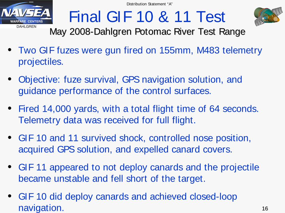
Final GIF 10 & 11 Test May 2008May 2008--Dahlgren Potomac River Test RangeDahlgren Potomac River Test Range
• Two GIF fuzes were gun fired on 155mm, M483 telemetry projectiles.
• Objective: fuze survival, GPS navigation solution, and guidance performance of the control surfaces.
• Fired 14,000 yards, with a total flight time of 64 seconds. Telemetry data was received for full flight.
• GIF 10 and 11 survived shock, controlled nose position, acquired GPS solution, and expelled canard covers.
• GIF 11 appeared to not deploy canards and the projectile became unstable and fell short of the target.
• GIF 10 did deploy canards and achieved closed-loop navigation.

Distribution Statement “A”
1717
GIF10 Test Summary
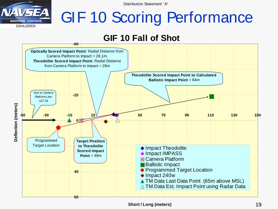
• GIF10 achieved closed-loop Navigation of a NATO-Standard Fuze eliminating ~84m of miss and splashing~48m from the programmed target coordinates.
• Launch Conditions should have resulted in an unguided miss in excess of 132m so the GIF fuze steered out about 64% of the error.
• Loss of nose roll control and (apparently) limited controlsurface deflections (<7 deg) adversely impacted thefinal accuracy.
• The guidance algorithm was properly estimating the final miss distance to within 2 m when nose control waslost.

Distribution Statement “A”
1818
Photo of GIF 10 Splash (48 M from target coordinate)
Barge
GIF10 Splash
48 meter Miss Distance Confirmed by Theodolites, IMPASS, Optical Cameras, and GIF Navigation System.
Distribution Statement “A”
1919
GIF 10 Scoring PerformanceGIF 10 Fall of Shot
-60
-40
-20
0
20
40
60
-50 -30 -10 10 30 50 70 90 110 130 150
Short / Long (meters)
Def
lect
ion
(met
ers)
Impact TheodoliteImpact IMPASSCamera PlatformBallistic ImpactProgrammed Target LocationImpact 240wTM Data Last Data Point (65m above MSL)TM Data Est. Impact Point using Radar Data
Optically Scored Impact Point: Radial Distance from Camera Platform to Impact = 28.1m.
Theodolite Scored Impact Point: Radial Distance from Camera Platform to Impact = 28m
Target Position to Theodolite
Scored Impact Point = 48m
Theodolite Scored Impact Point to Calculated Ballistic Impact Point = 84m
Programmed Target Location
Gun to Camera Platform Line
127.33

Distribution Statement “A”
2020
– Produce a SAASM P(Y) GPS receiver with reduced cost/ power requirements and sized to fit within a NATO standard fuze contour.
GPS SAASM Receiver Development

Distribution Statement “A”
2121
• No Existing Product Could Meet GIF Requirements
• Awarded Contract to Mayflower Communications Company, Inc. to Develop a SAASM GPS Receiver
– Low Cost (< $500)– Low Power (< 1W)– Small Size (< 2 in2)
GPS SAASM Receiver
C/A Version40mm dia.

Distribution Statement “A”
2222
• Phased approach:
– C/A Version w/ FPGA available now!
– ASICs developed:
• MAGIC C/A
• VANGUARD AJ
• BEACON RF
• INTEGRITY SAASM
- KDP-III-B
– P(Y) SAASM Receiver Available Mar. 2010
GPS SAASM Receiver Cont’d
P(Y) SAASM Version
40mmMMCX MMCX
INTEGRITY SAASM
VANGUARD AJ 7.5mm
BEACON RF

Distribution Statement “A”
2323
Up-Find & Anti-Jam Work• Under our existing Navy contract, Mayflower Communications
is tasked to:– Enhance the SAASM GPS receiver with an up determination
capability using Satellite phasing alone (no sensors needed).
– Complete the Anti-Jam module developed under a previous Navy contract.
– The Army has funded these two tasks.
• Mayflower and NSWCDD are working toward:– Proof of Up-Finding in a jammed environment, up to three
jammers, during 0 to 300Hz spin rates. – This testing will be done at Holloman AFB in mid May 09.

Distribution Statement “A”
2424
VIPER FUZE DESIGN

Distribution Statement “A”
2525
VIPER DESIGN, WHY?
• In FY 2006:– The Army’s 155mm, M549 RAP projectile became the
primary proof of concept projectile type (was M795). – CEP defined at 30-50 Meters– Design need not conform to a NATO standard
contour.
• The GIF fuze had marginal control authority on a M549 projectile body per wind tunnel data.
• The Navy decided to pursue an in house guided fuze design which performed independent of the projectile body.

Distribution Statement “A”
2626
“VIPER” Sectioned View
Power & Motor Control, Battery, S&A
HOB SensorElectrelease
Panel ReleaseFlight ComputerSAASM ReceiverAnti-Jam Module
GPS Antennas (4)
Panel Actuation

Distribution Statement “A”
2727
Mode 110% Drag Increase
All Drag Modes Have Spin
Control
Spin Maintenance
Anti-Roll Spin
Pro-Roll Spin
50% Drag Increase
60% Drag Increase
100% Drag Increase
Mode 1 Mode 1
Drag PanelsDon’t Rotate
Control PanelsThat Rotate
Drag “Throttled”At 10% to 50% (Modes 1 to 2)
Drag “Throttled” at 60% to 100% Between Modes 3 and 4
VIPER Control Modes(Momentum Method – Aimed Long of Target)
Drag Mode States Generally Increase as the Time to Impact Decreases
Mode 3Mode 2 Mode 4
Drag Maintenance

Distribution Statement “A”
2828
• All Fin-Stabilized munitions roll continuously due to fin cant. VIPER can shift to it’s “Lift Mode” Configuration.
0 deg Deflection +15 deg Deflection -15 deg Deflection
Control surfaces move together in a sinusoidal pattern as the airframe rolls. Drag panels can be deployed if necessary.
Airframe Rolls Continually
VIPER Control Modes(Lift Method)
Optional SAL Seeker

Distribution Statement “A”
2929
• In this mode, the VIPER control system modulates itscontrol surfaces in phase with the desired maneuver correcting both range and cross range errors.
• A CEP of less than 10m using GPS and approximately 1m with an Optional Semi-Active Laser (SAL) Seeker canbe achieved.
0 deg Deflection +15 deg Deflection -15 deg Deflection
Airframe Rolls Continually
VIPER Control Modes(Lift Method) Cont’d
Optional SAL Seeker

Distribution Statement “A”
3030
VIPER
QUESTIONSQUESTIONS