Embed Size (px)
Citation preview

Guidance for Industry and FDA Staff
Non-Clinical Engineering Tests and Recommended Labeling for
Intravascular Stents and Associated Delivery Systems Document issued on: April 18, 2010
This document supersedes the guidance “Non-Clinical Engineering Tests and Recommended Labeling for Intravascular Stents and Associated Delivery Systems” dated January 13, 2005.
For questions regarding this document, contact the Interventional Cardiology Devices Branch at or the Peripheral Interventional Devices Branch at (301) 796-7000.
U.S. Department of Health and Human Services Food and Drug Administration
Center for Devices and Radiological Health
Interventional Cardiology Devices Branch Peripheral Vascular Devices Branch
Division of Cardiovascular Devices Office of Device Evaluation
On August 18, 2015 FDA issued a guidance Select Updates for Non-Clinical Engineering Tests and Recommended Labeling for Intravascular Stents and Associated Delivery Systems. That guidance document updates and augments (but does not replace) this guidance.

Contains Nonbinding Recommendations
Preface
Public Comment Comments and suggestions may be submitted at any time for Agency consideration to Dockets Management Branch, Division of Management Systems and Policy, Office of Human Resources and Management Services, Food and Drug Administration, 5630 Fishers Lane, Room 1061, (HFA-305), Rockville, MD, 20852. When submitting comments, please refer to the exact title of this guidance document. Comments may not be acted upon by the Agency until the document is next revised or updated. Additional Copies Additional copies are available from the Internet at: http://www.fda.gov/MedicalDevices/DeviceRegulationandGuidance/GuidanceDocuments/ucm071863.htm. You may also send an e-mail request to [email protected] to receive an electronic copy of the guidance or send a fax request to 240-276-3151 to receive a hard copy. Please use the document number (1545) to identify the guidance you are requesting.

Contains Nonbinding Recommendations
Table of Contents I. INTRODUCTION............................................................................................................. 1
II. SCOPE ............................................................................................................................... 2
III. CONTENT AND FORMAT OF TEST DATA .............................................................. 4
A. Summary Reports .......................................................................................................................... 4
B. Test Reports.................................................................................................................................... 5
C. Test Protocols ................................................................................................................................. 6
IV. NON-CLINICAL ENGINEERING TESTS................................................................... 8
A. Material Characterization............................................................................................................. 8 1. Material Composition ...................................................................................................................... 8 2. Shape Memory and Superelasticity of Intravascular Stents............................................................. 9 3. Stent Corrosion Resistance .............................................................................................................. 9
B. Stent Dimensional and Functional Attributes ........................................................................... 11 1. Dimensional Verification............................................................................................................... 11 2. Percent Surface Area...................................................................................................................... 12 3. Foreshortening ............................................................................................................................... 12 4. Recoil for Balloon Expandable Stents ........................................................................................... 13 5. Stent Integrity ................................................................................................................................ 13 6. Radial Stiffness and Radial Strength ............................................................................................. 14 7. Radial Outward Force .................................................................................................................... 14 8. Mechanical Properties.................................................................................................................... 15 9. Stress /Strain Analysis ................................................................................................................... 16 10. Fatigue Analysis ............................................................................................................................ 19 11. Accelerated Durability Testing ...................................................................................................... 20 12. Particulate Evaluation .................................................................................................................... 21 13. Magnetic Resonance Imaging (MRI) Safety and Compatibility.................................................... 23 14. Radiopacity .................................................................................................................................... 25 15. Crush Resistance (Peripheral Indications Only) ............................................................................ 25 16. Kink Resistance (Peripheral Indications Only).............................................................................. 26 17. Additional Tests for Stents Intended for In-Stent Restenosis ........................................................ 26 18. Additional Tests for Stents Intended for Bifurcation Lesions ....................................................... 26
C. Delivery System Dimensional and Functional Attributes ........................................................ 27 1. Dimensional Verification............................................................................................................... 27 2. Delivery, Deployment, and Retraction .......................................................................................... 28 3. Balloon Rated Burst Pressure (Balloon Expandable Stents Only)................................................. 29 4. Balloon Fatigue (Repeat Balloon Inflations; Balloon Expandable Stents Only) ........................... 29 5. Balloon Compliance (Stent Diameter vs. Balloon Pressure; Balloon Expandable Stents Only)... 30 6. Balloon Inflation and Deflation Time (Balloon Expandable Stents Only) .................................... 31

Contains Nonbinding Recommendations
7. Catheter Bond Strength.................................................................................................................. 31 8. Tip Pull Test................................................................................................................................... 32 9. Flexibility and Kink Test ............................................................................................................... 32 10. Torque Strength ............................................................................................................................. 32 11. Coating Integrity ............................................................................................................................ 33 12. Stent Securement for Unsheathed Stents ....................................................................................... 34
D. Shelf Life....................................................................................................................................... 35
E. Biocompatibility ........................................................................................................................... 36
V. LABELING ..................................................................................................................... 39
A. Device Description ....................................................................................................................... 39
B. Indications for Use ....................................................................................................................... 40
C. Contraindications......................................................................................................................... 40
D. Warnings....................................................................................................................................... 40
E. Precautions ................................................................................................................................... 40
F. MR Environment ......................................................................................................................... 41
G. Overview of Clinical Studies ....................................................................................................... 41
H. Adverse Events ............................................................................................................................. 42
I. Clinical Studies............................................................................................................................. 44
J. Principal Safety and Effectiveness Table................................................................................... 45
K. Patient Selection and Treatment ................................................................................................ 46
L. Directions for Use......................................................................................................................... 46
M. Patient Materials.......................................................................................................................... 47
APPENDIX A: TEST SUMMARY CHECKLIST .................................................................. 48
APPENDIX B: APPLICABLE STANDARDS......................................................................... 51

Contains Nonbinding Recommendations
Guidance for Industry and FDA Staff
Non-Clinical Engineering Tests and Recommended Labeling for Intravascular
Stents and Associated Delivery Systems
This guidance represents the Food and Drug Administration's (FDA's) current thinking on this topic. It does not create or confer any rights for or on any person and does not operate to bind FDA or the public. You can use an alternative approach if the approach satisfies the requirements of the applicable statutes and regulations. If you want to discuss an alternative approach, contact the FDA staff responsible for implementing this guidance. If you cannot identify the appropriate FDA staff, call the appropriate number listed on the title page of this guidance.
I. Introduction
This guidance provides FDA’s current thinking on non-clinical engineering tests that are submitted in investigational device exemption applications (IDEs) and premarket approval applications (PMAs) to support the safety and effectiveness of intravascular stents and their associated delivery systems. This guidance also provides recommendations for labeling for these devices. FDA's guidance documents, including this guidance, do not establish legally enforceable responsibilities. Instead, guidances describe the Agency's current thinking on a topic and should be viewed only as recommendations, unless specific regulatory or statutory requirements are cited. The use of the word should in Agency guidances means that something is suggested or recommended, but not required.
Definition of Terms Used in this Guidance Intravascular Stent Intravascular stents are also known as endovascular stents or vascular stents. This document uses the term “intravascular stent” to refer to intravascular, endovascular, and vascular stents. An intravascular stent is a synthetic tubular structure intended for permanent implant in native or graft vasculature. The stent is designed to provide mechanical radial support after deployment; this support is meant to enhance vessel patency over the life of the device. Once the stent reaches the intended location, it is expanded by a balloon or self-expanding mechanisms defined below.
1
Contains Nonbinding Recommendations
Balloon Expandable Stent A balloon expandable stent is expanded by a balloon catheter. The diameter of the stent increases as the balloon diameter increases. The stent remains expanded after deflation of the balloon. Self-expanding Stent A self-expanding stent’s diameter increases from its pre-deployed size to its post-deployed size in the absence of balloon inflation or other mechanical assistance. The self-expanding quality can result from material properties or geometry or both. Stent Delivery System A stent delivery system delivers a stent to a target site and then deploys the stent. A stent delivery system for a balloon expandable stent consists of a balloon catheter. Self-expanding stent delivery systems may or may not include a balloon.
II. Scope This guidance document addresses self-expanding and balloon expandable extracranial intravascular stents and their associated delivery systems. The scope includes extracranial intravascular stents placed in coronary or peripheral arteries and saphenous vein grafts but is not limited to stents used in these locations; other vascular indications outside of the intracranial vasculature are also included. Intravascular stents, including balloon expandable and self-expanding stents, are class III devices whose product codes are given in the table below.
Table 1: Product Codes for Stents Addressed in this Guidance
Product Code Device
MAF Stent, Coronary
NIM Stent, Carotid
NIN Stent, Renal
NIO Stent, Iliac
NIP Stent, Superficial Femoral Artery
These devices require a premarket approval (PMA) application before marketing. See sections 513(a) and 515 of the Federal Food, Drug, and Cosmetic Act (the Act) and 21 CFR Part 814. Clinical studies conducted in the United States in support of a PMA approval must be conducted under the Investigational Device Exemptions (IDE) regulation, 21 CFR Part 812. FDA believes that the intravascular stents addressed by this guidance document are significant risk devices as defined in 21 CFR 812.3(m),1 and as such, are not exempt from the requirement to submit an 1 Refer to http://www.fda.gov/oc/ohrt/irbs/devices.html#risk.
2

Contains Nonbinding Recommendations
investigational device exemption (IDE) application (21 CFR 812.2(b), 812.20(a)(1). When an IDE application is required, a sponsor must not begin a clinical trial in humans in the United States until FDA has approved the application (21 CFR 812.20(a)(2), 812.42). Sponsors of such studies must comply with the following:
• IDE regulations (21 CFR 812) • Regulations governing institutional review boards (IRB) (21 CFR 56) • Informed consent (21 CFR 50). 2
After FDA has approved a device, clinical studies conducted in accordance with the indications in the approved PMA, including clinical design validation studies conducted in accordance with the quality systems regulation, are exempt from the investigational device exemptions (IDE) requirements. However, such studies must be performed in conformance with the regulations governing institutional review boards (21 CFR Part 56) and informed consent (21 CFR Part 50).
Non-vascular stents meant for use outside the vasculature are not included in the scope of this document. This document also does not include stents used in the intracranial vasculature. You should contact the Division of Reproductive, Abdominal, and Radiological Devices for information about biliary stents, the Division of Anesthesiology, General Hospital, and Infection Control Devices for information about non-vascular stents, or the Division of Ophthalmic, Neurological, and Ear, Nose, and Throat Devices for information about stents used in the intracranial vasculature. Some of the tests (and labeling recommendations) in this guidance are relevant to covered (NIV), drug-eluting (NIQ), and biodegradable stents, and stents used to treat aneurysms or dissections. However, FDA recommends additional testing to fully characterize these devices. For drug-eluting stents, please refer to the draft document Coronary Drug-Eluting Stents— Nonclinical and Clinical Studies.3 For other coated stents, FDA recommends that you assess the need for additional testing to address coating characterization, coating integrity, and coating durability. The Interventional Cardiology Devices Branch and the Peripheral Vascular Devices Branch are available to discuss additional testing details for these stents and indications. This guidance document supplements other FDA publications on PMA, PDP, and IDE applications and should not be construed as a replacement for those documents. For general information about these applications, see the CDRH Device Advice web site given below:
• PMAs (21 CFR Part 814): http://www.fda.gov/MedicalDevices/DeviceRegulationandGuidance/HowtoMarketYourDevice/PremarketSubmissions/PremarketApprovalPMA/default.htm
2 You should review the statutory definition of applicable clinical trial to determine if your trial must be registered to comply with the law. See PL 110-85, Section 801(a), (adding new 42 U.S.C. 282(j)(1)(A)). http://frwebgate.access.gpo.gov/cgi-bin/getdoc.cgi?dbname=110_cong_public_laws&docid=f:publ085.110.pdf Information can be submitted to ClinicalTrials.gov using the Protocol Registration System (PRS). For more information visit the PRS Information Page. 3 http://www.fda.gov/downloads/Drugs/GuidanceComplianceRegulatoryInformation/Guidances/UCM072193.pdf and http://www.fda.gov/downloads/Drugs/GuidanceComplianceRegulatoryInformation/Guidances/UCM072196.pdf
3

Contains Nonbinding Recommendations
• PDPs (21 CFR Part 814.19):http://www.fda.gov/MedicalDevices/DeviceRegulationandGuidance/HowtoMarketYourDevice/PremarketSubmissions/PremarketApprovalPMA/ucm048168.htm#pdp
• IDEs (21 CFR Part 812):http://www.fda.gov/MedicalDevices/DeviceRegulationandGuidance/HowtoMarketYourDevice/InvestigationalDeviceExemptionIDE/default.htm
This guidance also cites a number of voluntary standards, many of which are recognized by FDA. You may access a list of the FDA-recognized standards from the CDRH web site, http://www.accessdata.fda.gov/scripts/cdrh/cfdocs/cfStandards/search.cfm. See also the guidance, Recognition and Use of Consensus Standards, https://www.fda.gov/downloads/MedicalDevices/DeviceRegulationandGuidance/GuidanceDocuments/ucm077295.pdf
III. Content and Format of Test Data
A. Summary ReportsWe recommend that you present test data in a summary that includes the elements described below.
Table of Contents You should place a table of contents at the front of the document. Each line listing in the table of contents should refer to major section titles and the page numbers where each section can be found.
Test Summaries You should briefly describe all tests performed.
Test Data Summaries You should include test data summaries for all tests. The summaries should contain:
• minimum measured value (min)• maximum measured value (max)• mean• standard deviation of the test data (std. dev.).
Summary of Conclusions You should summarize your conclusions regarding whether the results support the safety and effectiveness of your device for each test.
4

Contains Nonbinding Recommendations
B. Test ReportsYou should include full test reports for all tests performed. Your test reports should include the sections described below.
Test Specimen Information Your test specimen description should include:
• number of test specimens• size (diameter, length, or other relevant dimensions) of all test specimens• rationale for the number of test specimens and sizes tested• whether the specimens represent the finished product• sterilization parameters and number of sterilization cycles applied to the test specimens.
Test Protocol You should submit your test method or protocol. It should contain enough detail that an individual familiar with intravascular stent testing will be able to interpret the test results.
Protocol Deviations You should describe any protocol deviations and their effect on the ability of the test data to support the safety and effectiveness of the device.
Test Parameters and Acceptance Criteria You should report the test parameters and acceptance criteria that you use, including:
• an explanation of and rationale for critical test parameters• specifications or acceptance and rejection criteria• a rationale for the specification or acceptance and rejection criteria based on the
clinical requirements of the device.
Raw Data We recommend that you include all raw data in appendices or on a CD-ROM, or make the raw data available for our review upon request.
Test Results You should summarize your test results and include statistical analysis when it is appropriate.
Data Analysis You should analyze the data, including any outlying points and anomalous results, and explain whether the data meet the given acceptance criteria.
Conclusions We recommend that you describe the conclusions drawn from the test results, and the clinical significance of the conclusions.
5

Contains Nonbinding Recommendations
C. Test ProtocolsYou should establish protocols for all experiments or computational analyses, including acceptance criteria when applicable, before you perform the tests. Established test protocols help to ensure consistent repetition of tests and allow comparison of data between test runs.
We are willing to informally review and provide comments on test protocols prior to conduct of a test, if there are aspects of a particular test that you feel might benefit from FDA input. While FDA does not approve test protocols, our input before testing may improve your ability to demonstrate the performance characteristics of your device.
Your test protocols should assess device performance when exposed to the most extreme clinical conditions that your device is likely to experience. Both device configuration and physiologic conditions affect the performance of devices in the human body. We recommend that you evaluate extreme device dimensions, tolerances, sizes, and any other important device parameters in your testing program. We also recommend that you examine the outer limits of physiologic variables such as blood pressure, vascular compliance, and anatomic types. You should clearly state all test conditions in the test protocol and support them with references to applicable literature, standards, or both.
Occasionally, the worst performing combination of device configuration and physiologic conditions occurs in the mid-range of the relevant variables. You should check for this situation when developing your protocols to ensure that you test the worst performing combination.
Several of the tests listed in this guidance do not apply to all intravascular stents and delivery systems. The designs or clinical indications to which these tests do apply are noted in their descriptions. We believe that each test helps to support the safety and effectiveness of intravascular stents for their stated indication. Each test’s clinical or engineering significance is described in Section V.
If you believe a test recommended in this guidance does not apply to your device, you should include a heading for the test in your test summary, followed by an explanation of why the test is not applicable. We will then be aware that you did not inadvertently omit it from your application.
Your explanation should include a rationale for why you do not think the test should be performed in order to support the safety and effectiveness of your device. Your rationale should clearly demonstrate, by reference to a Failure Modes and Effects Analysis (FMEA) or other risk analysis method, that the particular test or data set is not necessary or appropriate to support the safety and effectiveness of your device. Alternatively, you may identify measures you have taken to mitigate the risks associated with the device in the failure mode that would usually be evaluated using the test that you have not performed.
Intravascular stents have been in clinical use for over a decade and some designs are in their fourth or fifth generation. Some attributes may not be modified when changes are made in the design of a next-generation device. For a particular attribute, rather than providing original data for a next-generation design, it may be appropriate to reference previously tested stents in the
6
Contains Nonbinding Recommendations
same device family. However, a reference to previous generic device experience, for example, “alloy X has been used in stents,” generally is not adequate. If you choose to reference testing previously performed on already marketed stents, you should explain why the previous testing is relevant. If a particular attribute of the next-generation device is re-evaluated, a comparison of the results to those of the previous generation may be helpful.
Sample Selection
You should use a statistically significant sample size whenever possible. When using a statistically significant number of samples is not possible, you should provide a scientific rationale to support the number of samples tested in your test summary and test protocols, and provide reasonable assurance that the test results support the safety and effectiveness of the device.
All test samples should represent the finished product. Your devices should be sterilized by the final production process, including repeat sterilization cycles. You should note any tests that use samples that are not finished, sterilized product in the test summary and test protocols, and explain why doing so does not affect the applicability of the test results to the evaluation of safety and effectiveness of the device.
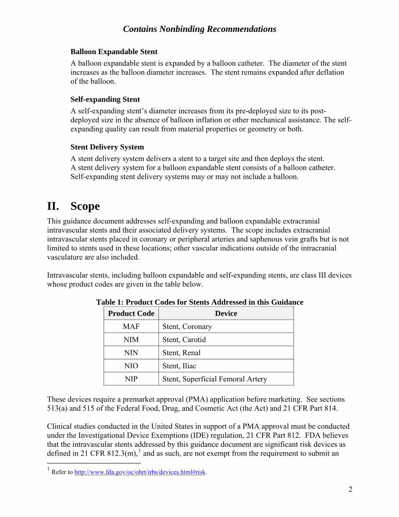
You should test the full range of sizes that you intend to commercially distribute. The recommended default paradigm is a 2 x 2 factorial of the largest and smallest diameters and lengths, also known as the “four corners” paradigm for each different stent design. We recommend a different set of sizes for some of the tests in Section V. Table 2 illustrates the four corners concept for a typical coronary stent. If you do not test a device using the four corners paradigm or the recommended sizes for a particular test, you should provide a scientific rationale to support the sizes that you do test in the test summary and test protocols. For some tests, we may recommend that you perform an analysis to identify the size or sizes that represent the worst case.
Table 2: Four Corners Test Paradigm Example
Stent Length (mm)
Stent Diameter (mm) 8 12 18 242.5 X X 3.0 3.5 4.0 X X
X = Recommended sizes for testing
7

Contains Nonbinding Recommendations
IV. Non-Clinical Engineering TestsA. Material Characterization
1. Material Composition
SignificanceMaterial composition testing documents a baseline for evaluation of the effects offuture changes in materials.
RecommendationWe recommend that you specify the device characteristics described below. If yourstent material is identical to your previously marketed stents, we recommend that youidentify the stent(s) and material(s) to which it is identical.
Stent and Delivery System Materials We recommend that you list materials by trade or common name, for example, 316L stainless steel.
Generic Chemical Formulation We recommend that you list formulations of all materials by generic name, for example, 18 Cr-14 Ni-2.5 Mo stainless steel. We recommend that you reference any applicable standard designations such as ASTM F138.4
Chemical Composition and Formulation We recommend that you provide detailed specifications for the chemical composition or formulation of materials (or both) for any new materials, alloys, or formulations with no history of use in intravascular stents or PTCA catheters.
Surface finish is known to affect other material properties for nitinol (e.g. corrosion, nickel ion release). Therefore, for stents containing nitinol, we recommend that you characterize the material surface of your finished product in terms of passivation layer microstructure vs. depth. Special attention should be paid to surfaces which might include heat-affected zones (e.g., from laser cutting), or to geometric areas which may be affected differently by finishing (e.g., internal angles).
Material Certification We recommend that you provide documentation to certify that incoming raw material conforms to specifications. We recommend that you submit supplier certification, incoming quality control test results, or equivalent documentation.
4 ASTM F138 Standard Specification for Wrought 18Chromium-14Nickel-2.5Molybdenum Stainless Steel Bar and Wire for Surgical Implants
8

Contains Nonbinding Recommendations
2. Shape Memory and Superelasticity of Intravascular Stents
SignificanceThe transition temperature of nitinol or other shape memory and superelasticmaterials determines specific shape memory and superelastic properties.
RecommendationWe recommend that you document the following properties for any shape memory orsuperelastic materials present in your stent.
Austenite Finish Transition Temperature (Af) We recommend using the methods described in ASTM F2004,5 ASTM F2082,6 or equivalent methods.
Mode of Action We recommend that you describe the mode of action (e.g., thermal shape memory or superelasticity) by which the stent transitions to the specified size and shape.
3. Stent Corrosion Resistance
SignificanceStent corrosion can cause or contribute to premature stent failure. In addition,corrosion byproducts may be toxic or cause other adverse biological and tissueresponses.
RecommendationWe recommend that you address the corrosion properties of your device describedbelow. If some of these characteristics do not apply to your device, we recommendthat you explain this in your application.
Fretting Corrosion We recommend that you address the potential for fretting corrosion between two stents since there is a reasonable expectation of stent overlap during clinical use for most indications. We recommend that the examination of samples for fretting corrosion be incorporated as part of fatigue/durability testing (see Section B.11. Accelerated Durability Testing). You should ensure that overlapping stents are in contact with one another and that the setup does not preclude micromotion between strut elements. For coronary stents, because tortuosity of a target deployment site could result in increased micromotion between components or multiple stents, the mock deployment site should be bent to a worst-case clinically relevant radius of curvature, which should be smaller than most anatomical
5 ASTM F2004 Standard Test Method for Determination of Transformation Temperature of Nickel-Titanium Alloys by Thermal Analysis 6 ASTM F2082 Standard Test Method for Determination of Transformation Temperature of Nickel-Titanium Shape Memory Alloys by Bend and Free Recovery
9

Contains Nonbinding Recommendations
situations encountered in clinical use. For example, for most coronary indications, FDA recommends a 15mm radius of curvature as this represents worst case for 90% of the population based on published angiographic measurements.7 For other indications such as use in coronary bifurcations, please provide a similarly robust clinical rationale for the radius of curvature selected.
We recommend conducting a visual (e.g., SEM) inspection of samples after fatigue/durability testing for evidence of corrosion.
Results from testing through one year time equivalent should be provided in support of an IDE application. Results from testing through ten years time equivalent should be provided when they are available, but not later than at the time of PMA submission. A scientific rationale for the number of samples evaluated for fretting corrosion should be provided.
Pitting and Crevice Corrosion Potential We recommend that you characterize the corrosion potential of your stent with any potential surface damage that may result from fatigue. We recommend testing the same samples used in the fretting corrosion evaluation described above according to the method in ASTM F2129.8 Specifically, one stent from each overlapping pair subjected to fatigue cycling should be evaluated for pitting and crevice corrosion potential while the other stent from each pair is evaluated for fretting corrosion as described above. Test reports for pitting and crevice corrosion potential testing should include the recorded potentials as well as the polarization curves.
Results from testing through one year time equivalent should be provided in support of an IDE application. Results from testing through ten years time equivalent should be provided when they are available, but not later than at the time of PMA submission.
If results do not indicate an acceptable pitting and crevice corrosion potential, you should consider characterizing the corrosion potential of the finished, as manufactured stent to determine if the corrosion potential of your stent is affected by fatigue.
You may use literature citations or previous experience with stents to address this issue; however, the materials, design, and fabrication processes specific to your stent may reduce or eliminate the applicability of generic literature. For example, the pitting corrosion resistance of nitinol is sensitive to processing variables such as heat treatment and electropolishing; therefore, for a nitinol stent, you should characterize the corrosion potential of the finished stent.
7 Liao R, Green NE, Chen SY, Messenger JC, Hansgen AR, Groves BM, Carroll JD. Three – dimensional analysis of in vivo coronary stent – coronary artery interactions. International Journal of Cardiovascular Imaging. 2004 Aug;20(4):305-13. 8 ASTM F2129 Standard Test Method for Conducting Cyclic Potentiodynamic Polarization Measurements to Determine the Corrosion Susceptibility of Small Implant Devices
10

Contains Nonbinding Recommendations
Galvanic Corrosion If your stent contains more than one type of metal, such as a base stent material with added marker bands, we recommend that you demonstrate the design’s resistance to galvanic corrosion. If you expect that your stents will be overlapped during clinical procedures, and the contacting or overlapping stents may be made of different materials, we recommend that you address the potential for galvanic corrosion between stents. In this case, we recommend that you use the marketed stent with the highest galvanic coupling with your stent material in your evaluation. We recommend the methods described in ASTM G719 or their equivalents. These methods may be modified to provide for testing of finished stents, for example, by incorporating the experimental setup described in Appendix X3 of ASTM F2129.
Testing should be conducted even if an alloy conforms to a specific standard because manufacturing processes can affect the galvanic corrosion potential of the finished product.
B. Stent Dimensional and Functional Attributes1. Dimensional Verification
SignificanceAccurate stent dimensions help the physician to achieve proper stent sizing andaccurate placement in the body. They also affect the functional behavior of the stent.
RecommendationFDA recommends that you provide the information described below that applies toyour stent. We recommend the methods used in ASTM F208110 or their equivalents.At a minimum, you should take measurements at each end and in the middle of thestent and at two circumferential points 90˚ apart (for a total of six measurements).You should take additional measurements as appropriate based on device design.
Un-expanded Stents We recommend that you provide dimensional specifications and tolerances for un-expanded stents.
Balloon Expandable Stents We recommend that you measure and report the expanded diameter of balloon expandable stents. You may do this as part of the process of creating a compliance chart. See Section C. Delivery System Dimensional and Functional Attributes, 5. Balloon Compliance.
9 ASTM G71 Standard Guide for Conducting and Evaluating Galvanic Corrosion Tests in Electrolytes. 10 ASTM F2081 Standard Guide for Characterization and Presentation of the Dimensional Attributes of Vascular Stents
11
Contains Nonbinding Recommendations
Self-Expanding Stents We recommend that you verify the unconstrained expanded diameter of self-expanding stents with measurement data.
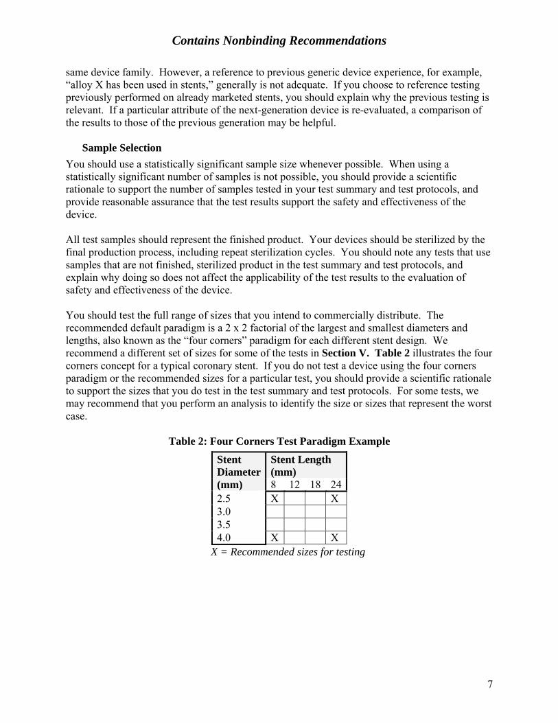
2. Percent Surface Area
SignificanceThe area over which a stent contacts a vessel may affect the biologic response of thevessel. The amount of open, non-contact area may influence tissue prolapse oringrowth.
RecommendationWe recommend that you report the percent surface area of the stent for both thesmallest and largest nominal expanded diameters for each stent design. Werecommend that you evaluate different lengths only if you expect that the percentsurface area varies significantly with stent length. We recommend that you measureor calculate the contact area of the stent structure, and express the final value as apercentage of the reference area, as shown below:
Percent Surface Area = 100 x (Area in Contact with Vessel ÷ Full Cylindrical SurfaceArea)
(The reference area is defined as the full cylindrical surface area at the expanded stent diameter.) We recommend that you apply the methods described in ASTM F2081 or their equivalents.
3. Foreshortening
SignificanceForeshortening, i.e., dimensional changes that may occur when deploying a stent,influences final stent length. Knowledge of the foreshortening characteristics aids inproper stent length selection and proper placement in the body.
RecommendationFDA recommends that you report the decrease in length of the stent between thecatheter-loaded condition and the deployed diameters up to the maximum labeleddiameter.
We recommend that the reported value reflect the maximum nominal diameter. Werecommend that you report the results in terms of a percentage of the loaded length asshown below:
Percent Foreshortening = 100 x (Change in Length ÷ Loaded Length).
We recommend that you apply the methods described in ASTM F2081 or their equivalents.
12
Contains Nonbinding Recommendations
See Section VIII. Labeling for recommendations on data presentation of the percent foreshortening of self-expanding stents.
4. Recoil for Balloon Expandable Stents
Significance The recoil behavior of balloon expandable stents influences proper device selection, sizing, acute post-implant results, and long-term clinical outcomes. Recoil is a function of stent design and material selection; therefore, knowledge of stent recoil helps to characterize the behavior of a particular stent design. Recommendation We recommend that you report the measured change in diameter of your stent between post-balloon expansion and after balloon deflation. We recommend that you measure and report values for each labeled stent diameter. If you expect that the percent recoil varies significantly with length, we recommend that you evaluate recoil for different stent lengths at various points along the length of the stent, including the ends. The number of locations along the length of the stent at which recoil is measured should be determined by initial assessment of the stent geometry. We recommend that you present the results as a percentage of the expanded diameter. We recommend the methods described in ASTM F207911 or their equivalents.
5. Stent Integrity
Significance Stent defects, whether a result of manufacturing flaws or subsequent damage, can contribute to clinical complications. Laser cutting or other manufacturing processes may induce flaws that are not completely removed by polishing. Plastic deformation during loading or balloon expansion may cause cracks or other damage. Self-expanding stents that are stored loaded in a delivery system may exhibit permanent set or changes in expansion characteristics as a result of time or sterilization or both. Recommendation We recommend that you examine your deployed stent and report any evidence of stent defects such as, but not limited to:
• cracks • scratches • permanent set • coating delamination.
11 ASTM F2079 Standard Test Method for Measuring Intrinsic Elastic Recoil of Balloon expandable Stents
13

Contains Nonbinding Recommendations
We recommend that you use optical or electron microscopy, or both to look for defects. We recommend that you support the level of magnification that you use on the basis of the size of the defect that your inspection attempts to detect. When you are looking for post-deployment damage, we recommend that you examine or inspect:
• balloon expandable stents, after expansion to the largest diameter listed in your labeling
• self-expanding stents, after expansion to the unconstrained diameter. 6. Radial Stiffness and Radial Strength
Significance Radial stiffness and stent recoil determine the diameter of balloon expandable stents deployed in compliant vessels. Radial stiffness and radial strength characterize the ability of the stent to resist collapse under short-term or long-term external loads. Recommendation We recommend that you report a value for the following:
• radial stiffness, i.e., the change in stent diameter as a function of uniformly applied external radial pressure; and
• radial strength, i.e., the pressure at which your stent experiences irrecoverable deformation.
FDA recommends that you measure and report values for each labeled stent diameter. If you expect that the radial stiffness varies significantly with length, we recommend that you also evaluate different stent lengths. We recommend that you support the diameter or pressure range used in your tests for radial stiffness. The diameter and pressure range will probably vary depending on your stent’s intended target site.
7. Radial Outward Force
Significance It is important to characterize the radial outward force of self-expanding stents. Excessive radial force could injure the surrounding tissue, while a radial force that is too low can result in incomplete apposition of the stent to the vessel wall. Recommendation We recommend that you measure the radial force exerted by self-expanding stents against the vessel wall after deployment. If a particular stent size or model is indicated for use in a range of vessel sizes, your assessment should cover the range of possible vessel sizes, or should include a rationale for not assessing the entire size range to be marketed. We recommend that you evaluate different stent lengths if you expect that the radial force varies as a function of the total stent length. In addition, if
14

Contains Nonbinding Recommendations
you expect that the radial force of your stent is not axially uniform (for example, if your stent has a tapered length), we recommend that you measure the radial force at multiple locations along the length of the stent. The specifications for radial outward force should include both minimum and maximum values.
8. Mechanical Properties
Significance Raw material properties determine incoming material quality and uniformity, and predict subsequent thermomechanical effects. Thermomechanical properties of the implanted stent affect clinical performance, as well as stress and fatigue behavior. Recommendation We recommend that you specify the mechanical properties listed below for the stent raw material(s).
Mechanical Properties of the Raw Material(s) • ultimate tensile strength (UTS) • yield strength (YS) • elongation • plateau stresses, for nitinol • elastic strain limits, for nitinol.
Post-Processing Mechanical Properties FDA also recommends that you report the stress-strain response of the stent after deployment. We recommend that you present the stress-strain behavior in a plot or graph that shows both loading and unloading. We recommend that you report the following post-processing mechanical properties of your stent:
• UTS • YS • elongation • elastic modulus • Poisson ratio • endurance limit • plateau stresses, for nitinol • elastic strain limits, for nitinol.
In addition, reporting other mechanical properties at previous stages of manufacture, may allow characterization of your material for use in your stress/strain analysis. See Section 9. Stress/strain Analysis. We recommend that you determine the stress-strain response, endurance limit, and post-processing mechanical properties through physical experiments or computational models that simulate stent material properties, manufacturing, and deployment processes. If you cite any quoted literature or
15

Contains Nonbinding Recommendations
handbook values, we recommend that you explain how they are relevant to your device. Since the material properties of nitinol are widely variable depending on processing, we recommend for nitinol devices that you perform physical experiments on actual post-processing samples to determine the mechanical properties of your stent. We also recommend that you use and reference standard test methods whenever possible, and describe any nonstandard test methods in detail.
9. Stress /Strain Analysis
Significance Failure of a loaded stent may result in loss of radial support of the stented vessel or in perforation of the vessel by the stent struts. Stress/strain analysis, combined with fatigue analysis and accelerated durability testing, provides an indication of device durability. Recommendation FDA recommends that you include the following elements in your stress/strain analysis and test report for each stent design.
Computational Model and Inputs We recommend that you clearly identify and explain the sources and values of all inputs and assumptions used to create the stress/strain analysis model. You should identify any software used for analysis. We recommend that finite element analysis reports include the element types used to model the stent, loading surfaces, and boundary conditions. We also recommend that you indicate if mesh refinement analysis was performed and clearly describe how you model the surrounding vessel/tissue and the type of contact elements used. Specifically, we recommend that you consider the following:
• Model Geometry We recommend that you clearly describe the stent and vessel geometry used. If symmetry is used, we recommend that you explain why this is appropriate for your model. If you do not model all of your stent sizes, we recommend that you explain why the modeled stent size is the worst case with respect to critical stresses. We recommend that you address the effect of dimensional variation within allowable tolerances on the results of the stress/strain analysis (i.e., maximum critical stress). We recommend that you provide a justification for the physiological relevance of your vessel model parameters (e.g., vessel compliance).
16
Contains Nonbinding Recommendations
• Type of Element & Mesh Refinement Analysis We recommend that you specify the number and type of elements used in your mesh, including any mesh refinement in transition regions or regions of complex geometry. We recommend that you perform a mesh refinement analysis to ensure that the solution is independent of element size. If you do not believe mesh refinement analysis is necessary for your model, we recommend that you provide a justification for not conducting such an analysis.
• Contact Elements
We recommend that you specify the type of contact defined between any 2 contacting bodies modeled in your analysis; e.g., the vessel and outer surface of your stent.
• Material Properties (Constitutive Model)
We recommend that you clearly describe the material stress/strain behavior of your stent in graphical and equation form. This discussion should include, but is not limited to the following considerations:
o Linear vs. non-linear o Isotropic vs. anisotropic o Temperature-dependent behavior o Raw vs. processed material.
• Finite Element Analysis (FEA) Validation We recommend that you validate your FEA (material properties, geometry, and boundary conditions) with experimental bench testing. For example, you could perform radial loading of your device and compare the force-displacement results with FEA of a simulated radial loading experiment.
Stress/Strain History
FDA recommends that you include the entire stress history of the device in each loading step in order to incorporate the effects of residual stresses. The entire stress history may include, but is not limited to:
• manufacturing (fabrication, annealing, electropolishing, heat-setting, etc.) • loading onto the delivery system and/or crimping • expansion/deployment (including over- or underexpansion into an elastic
vessel, if applicable) • stent recoil • physiologic loading conditions.
If you believe that you do not need to model the entire stress history, we recommend that you use material properties that are consistent with the starting point of your analysis. We recommend that the material properties accurately
17

Contains Nonbinding Recommendations
reflect the processing history of the stent as described in Section 8. Mechanical Properties. We also recommend that you explain why the omitted loading steps either do not affect the stent fatigue life or are accounted for in your model. Physiologic Loading Conditions The modeled physiologic loading mode will depend on the implantation site and may include, but is not limited to the following:
• radial dilation • torsion • bending • axial tension • axial compression • crushing, including focal, non-focal, or uniform radial compression.
We recommend that you address the list above as well as any other relevant loading conditions when you develop the model for your stent. If you expect that your stents will be overlapped during clinical procedures, then we recommend that you address the possibility of the additional stress concentrations caused by overlapping stents. We believe that most coronary stents indicated for use in non-bifurcated vessels should be modeled using radial dilation in a static bend to represent potential tortuosity of the target lesion. We recommend that you perform your stress/strain analysis such that the stent is in a mock deployment site bent to a clinically relevant radius of curvature as described in Section IV. Non-Clinical Engineering Tests A. Material Characterization 3. Stent Corrosion Resistance – Fretting Corrosion. You may also wish to consider dynamic bending to better evaluate the performance of your stent in clinical use conditions. For non-coronary stents, long stents, and coronary stents used in other vessel configurations such as bifurcation lesions, we recommend that you determine the relevant loading conditions. Results: Stress or Strain Critical Locations and Magnitude We recommend that you identify the critical locations of stress or strain on the stent using finite element analysis and address the effect of dimensional variation within allowable tolerances on the results. We recommend that you report the location and magnitude of all maximum tensile and compressive stresses or strains as well as the stress-strain distribution using graphics. The stress or strain measure used should be clearly defined (e.g., principal stresses, Von Mises stresses, etc.). We recommend that you explain why the measure used is reasonable considering your constitutive model. Additionally, we recommend that you explain what safety issues may arise if the stent fails in the region of maximum stress or strain.
18

Contains Nonbinding Recommendations
If you choose to perform a strain-based analysis instead of a stress-based analysis, we recommend that you explain why the strain-based analysis is more appropriate for your device.
10. Fatigue Analysis
Significance Failure of a stent due to fatigue may result in loss of radial support of the stented vessel, thrombus formation or focal restenosis, or in perforation of the vessel by the stent struts. Fatigue analysis, combined with stress/strain analysis and accelerated durability testing, provides an indication of device durability. Recommendation FDA recommends that you determine the fatigue resistance of the stent to physiologic loading using a Goodman analysis or another fatigue life analysis method. We recommend that your test report include the following elements.
Modeled Stent Sizes If you do not analyze all stent sizes, we recommend that you explain why the modeled stent size is the worst case for fatigue life. Inputs and Assumptions FDA recommends that you use the mean and alternating stresses/strains obtained from the stress/strain analysis as input for the fatigue life determination. We recommend that you clearly identify and support all inputs and assumptions used in your analysis. If you use literature values for any material properties, we recommend that you identify the source of the data and support that your values correspond to the as-implanted condition of the material. If you expect that your stents will be overlapped during clinical procedures, we recommend that you address the possibility of the additional stress concentrations caused by overlapping stents. We believe that most coronary stents indicated for use in non-bifurcated vessels should be modeled using radial dilation in a static bend to represent potential tortuosity of the target lesion. We recommend that you perform your stress/strain analysis such that the stent is in a mock deployment site bent to a clinically relevant radius of curvature as described in Section IV. Non-Clinical Engineering Tests A. Material Characterization 3. Stent Corrosion Resistance – Fretting Corrosion. Since the material properties of nitinol are widely variable depending on processing, we recommend for nitinol devices that you perform physical experiments on actual post-processed samples to determine the mechanical properties of your stent, and use these values in your analysis.
19

Contains Nonbinding Recommendations
Results We recommend that you provide a Goodman diagram or other graphic that compares the stresses at critical locations in the stent to the mechanical properties of the stent material. We recommend that you report fatigue safety factors in a table and explain how the safety factors were calculated.
If you choose to perform a strain-based analysis instead of a stress-based analysis, we recommend that you explain why the strain-based analysis is more appropriate for your device.
11. Accelerated Durability Testing
SignificanceAccelerated durability testing validates fatigue analysis. It evaluates failure modessuch as fretting, abrasion, wear, and fracture. Durability testing can help in theidentification of device conditions, such as manufacturing anomalies, that were notmodeled using analytical or computational methods.
RecommendationFDA recommends that accelerated durability testing of your stent address thefollowing issues.
Sample Size We recommend that you determine sample size based on your fatigue analysis, including boundary conditions, loading conditions, safety factors, and any other relevant factors.
We recommend that you consider a stent as one test specimen when you report reliability calculations and results. We recommend that you consider the stent as one test specimen regardless of the symmetries present in apices, repeat units, or struts of the stent.
Sizes Tested We recommend that you select and support the stent size or sizes tested based on the stress and fatigue analyses or other factors. We recommend that the sizes tested represent the worst case fatigue life of your device.
Test Duration We recommend that you test the durability of your stent to the equivalent of ten years of real-time use under pulsatile flow and physiologic loading that simulates blood pressure conditions in the human body. We believe that ten years of durability data provides sufficient proof of safety of the device for most patients. If you perform a rigorous and conservative fatigue analysis that indicates an acceptable analytical safety factor, you may propose to complete long-term durability testing concurrent with clinical trials and to submit the final results
20

Contains Nonbinding Recommendations
when they are available, but not later than at the time of PMA submission. In this case, results from testing through a minimum of one year time equivalent should be provided in support of an IDE application.
Loading and Boundary Conditions FDA recommends that you perform long-term durability testing that models the physiological loads and boundary conditions that your stent is likely to experience under its intended use.
We recommend that you address any other types of cyclic loading, such as bending, that you anticipate your stent will experience when used as intended, and incorporate these types of loading into your testing where possible. We recommend that you explain the clinical relevance of the loading conditions used for the accelerated durability testing. If the conditions you choose differ from the loading conditions that you modeled in the stress and fatigue analyses, we recommend that you report and explain the differences.
Stent systems should be tracked through a clinically relevant test fixture prior to deployment.
Overlapping Stents If you expect that your stents will be overlapped during clinical procedures, we recommend that you address the possibility of the additional risk of stent failure caused by wear or other factors. Therefore, you should test overlapping stents as part of the durability experiment.
Deployment Site The testing should be relevant for your intended clinical use and condition. For example, we believe that most coronary stents indicated for use in non-bifurcation vessels should be deployed in a mock vessel bent to a clinically relevant radius of curvature as described in Section IV. Non-Clinical Engineering Tests A. Material Characterization 3. Stent Corrosion Resistance – Fretting Corrosion.
Results We recommend that you relate the outcome of your test to the stress and fatigue analysis results.
12. Particulate Evaluation
SignificanceParticulate matter can be generated by the manufacturing process or from thebreakdown of any coating (e.g., hydrophilic coating) or from the stent platform, stentdelivery system, or product packaging. If particles are introduced in the bloodstreamduring stent delivery or deployment, they may present an embolic risk to the patient.
21

Contains Nonbinding Recommendations
Measurement of the total quantity and size of particulates a device system may generate is an indication of embolic risk. Therefore, evaluation of particulate generation, size, and its potential impact on the end organ served by the stented vessels is critical.
Recommendation We recommend that you measure the total number of particulates and size of the particulates generated during the simulated delivery and deployment of all coronary stents and any other stents that are determined to be high particulate risk based on a risk analysis that takes into account the clinical setting and susceptibility of the end organ to damage from emboli.
Test Samples You should conduct all testing on the finished product subject to all manufacturing processes including sterilization. You should evaluate a robust number of stents from multiple stent lots (minimum of 3 batches) and specify the number of samples (we recommend that a sample equals one stent, not a strut or portion of a stent) used, the stent size(s), and the number of stent lots for each test. We recommend that you implement a sampling plan to examine multiple lots of product to assess both inter- and intra- lot variability. You should perform testing on sizes that represent four corners of the stent design (see Table 2 above) as well as an intermediate size. You should provide a scientific or statistical justification for the selection of samples.
It may be possible to combine the Particulate Evaluation with Delivery, Deployment and Retraction testing (see Section IV. Non-Clinical Engineering Tests C. Delivery System Dimensional and Functional Attributes 2. Delivery Deployment and Retraction) and/or with Coating Integrity testing (see Section IV. Non-Clinical Engineering Tests C. Delivery System Dimensional and Functional Attributes 11. Coating Integrity) but you should take care to ensure that only minimal additional handling of the test samples is required for the coating integrity evaluation such that particulates are neither lost nor generated.
Test Methods We recommend using an in vitro model intended to mimic in vivo physiologic and anatomic worst-case conditions (e.g., tortuous path, aqueous environment) to evaluate particulates. For coronary indications, FDA recommends the tortuous path described by Figure X2.4 of ASTM F239412. If you expect your stents may be deployed in an overlapped configuration during clinical procedures, we recommend that you measure particulates generated during deployment of two overlapping stents in a mock vessel. For coronary stents, the mock vessel should be bent to a clinically relevant radius of curvature as described in Section IV. Non-Clinical Engineering Tests A. Material Characterization 3. Stent
12 ASTM F2394 Standard Guide for Measuring Securement of Balloon Expandable Vascular Stent Mounted on Delivery System
22

Contains Nonbinding Recommendations
Corrosion Resistance – Fretting Corrosion. The stent should be in direct contact with the simulated vessel without the use of other coatings, lubricants, sheaths, or protective wraps between the stent and the simulated vessel. To ensure measurement of the total number of particles that could be potentially introduced into the bloodstream, the stent delivery system should be inserted into the text fixture to the extent which it would be inserted in clinical use and expanded to rated burst pressure (for balloon-expandable stents) or the maximum labeled diameter (for self-expanding stents). Additionally, any accessory devices required for the placement of the product should be used in this evaluation. The total number of particulates including those from the stent, delivery system, and accessory devices should be reported in each of three size ranges: ≥10µm, ≥25µm, and at the largest size for which validation yields ≥75% recovery. At a minimum, the largest size should be ≥50µm. Appropriate precautions should be implemented to ensure that the particles are suspended during sampling for particle counting and sizing to minimize artifacts from the test system. Validation You should describe and validate particle counting and sizing methods. We recommend that a known amount of various particle sizes be introduced into the test setup and the amount of particles recovered quantified. The number of particles recovered should closely approximate the number artificially introduced into the system. For a system to be considered validated, ≥90% recovery should be demonstrated for the ≥10µm and ≥25µm size ranges.
13. Magnetic Resonance Imaging (MRI) Safety and Compatibility
Significance MRI of patients with stents poses the following potential hazards:
• movement of the implant, resulting in tissue damage or misplacement • heating of the implant and subsequent tissue damage • image artifacts that may render the MR images uninterpretable or misleading.
Recommendation FDA recommends that you address the issues affecting safety and compatibility of your stent in the MRI environment as described in the Guidance for Industry and FDA Staff: Establishing Safety and Compatibility of Passive Implants in the MR (Magnetic Resonance) Environment.13
Test Environment We recommend that you report details of the test environment, such as, but not limited to:
• magnetic field strength in Tesla (T) • maximum spatial gradient
13 http://www.fda.gov/MedicalDevices/DeviceRegulationandGuidance/GuidanceDocuments/ucm107705.htm
23

Contains Nonbinding Recommendations
• maximum time rate of change of magnetic field (dB/dt) • local specific absorption rate (SAR) at the position of the stent in the
phantom • calorimetric assessed phantom averaged whole body specific absorption
rate. • heating data versus time • close-up photos of temperature probe placement • overview photos of the placement of the stent in the phantom • details about the phantom gel • details about the pulse sequence • temperature increase at the location of the stent but without placing the
stent in the gel • close-up photo of the stent including the stent dimensions • B1rms according to IEC 60601-2-33.
We recommend that the magnetically induced deflection force for a stent composed of ferromagnetic material be determined at the location where the spatial gradient of the magnetic field is a maximum. The magnetically induced deflection force for a stent composed of paramagnetic material should be determined at the location where the product of the magnitudes of the magnetic field and the spatial gradient of the magnetic field ( B B∇ ) is a maximum. (It is possible that this location is off the central axis of the bore of the scanner.) The magnetically induced torque is a function of the field strength, and so should be measured where the static magnetic field is the greatest, within the bore of the magnet. Note that the physical locations of the maximum torque and displacement force will almost certainly be different. You should perform all testing on finished devices.
Please note that for radiofrequency (RF) heating testing using the phantom described in ASTM F2182 or equivalent, anatomical positioning of the stent in the phantom does not reliably predict the implant heating in the patient. Therefore, you should provide calorimetry data to demonstrate that your test conditions are applicable to reasonable worst-case clinical conditions for heating. Because the potential for device heating is impacted by the relationship between the conductive length of the device and the wavelength of the RF, higher magnetic field strengths do not necessarily result in worst-case test conditions for a particular device. Therefore, we recommend that you test your device at all field strengths for which you are seeking MR Conditional labeling. Given the prevalence of 1.5 T and 3.0T MR systems, we recommend that, at a minimum, you test your device using both of these systems unless you are able to provide compelling evidence that a particular system represents a worst-case situation for your device. If you anticipate that your stents will be overlapped during clinical procedures, we recommend that you consider the total length of overlapping stents in your determination of worst case test conditions and test accordingly.
24
Contains Nonbinding Recommendations
There is a large variability across available MR scanners of the actual specific absorption rate (SAR) delivered. In general, the actual SAR delivered is much lower than the value displayed on the scanner console. Therefore, we recommend that you determine the actual SAR delivered to your stent during testing by calorimetry and report this in the labeling. We recommend that your labeling contain information for the patient and medical personnel about any potential hazards associated with MRI as a result of the presence of the implanted stent. See Section VIII. Labeling for examples of language describing the MRI compatibility of stents in labeling.
14. Radiopacity
Significance Stent visibility using angiographic or radiographic imaging or both generally assures proper stent placement and allows follow-up and secondary treatment. Recommendation FDA recommends that you evaluate the radiopacity of your stent at the smallest diameter and the shortest length during the following stages in the life of the stent:
• delivery • deployment, if separate from delivery • after implantation.
We recommend that you provide a qualitative or quantitative indication of the visibility of the stent on real-time and plane film x-ray. It is acceptable to use data from images of animal implants, in vitro phantoms, or equivalent models.
15. Crush Resistance (Peripheral Indications Only)
Significance Peripheral stents in some anatomic locations may experience external, non-cardiac, focal, or distributed loads. These loads could cause stent deformation and, possibly, adverse clinical consequences. Recommendation FDA recommends that you demonstrate the ability of your stent to recover its desired size and shape after application and removal of external loads, deformations, or both. We recommend that you support the nature, location, and extent of all external loads and deformations based on the intended implantation site, for example, the carotid or femoral arteries. Testing may include the application of focal loads, axially distributed loads, or both, depending on the target vasculature. We recommend that you report the change in unloaded stent dimensions after the application and removal of all of the specified loads and displacements.
25

Contains Nonbinding Recommendations
26
16. Kink Resistance (Peripheral Indications Only)
Significance Peripheral stents used in some anatomic locations will bend during normal body motion, such as knee flexion. Such bends could cause stent deformation and possible adverse clinical consequences. Recommendation We recommend that you determine the smallest radius of curvature that your stent can withstand without kinking, and demonstrate that the stent recovers its original size and shape after testing. We recommend that you support the nature, location, and extent of all external loads and deformations based on the intended implantation site, for example, the carotid or femoral arteries.
17. Additional Tests for Stents Intended for In-Stent Restenosis
Significance Deployment of stents within previously implanted stents to treat in-stent restenosis could result in increased corrosion potential, stress, fatigue, wear, coating damage, and particulate generation due to stent to stent interactions. Recommendation If you intend to label your stent for in-stent restenosis, we recommend you repeat the following tests within an expanded stent (i.e., with 100% overlapped stent pairs):
• Fretting Corrosion (refer to Section A.3) • Stress/Strain Analysis (refer to Section B.9) • Fatigue Analysis (refer to Section B.10) • Accelerated Durability Testing (refer to Section B.11) • Particulate Evaluation, if appropriate for the indications for use (refer to
Section B.12).
18. Additional Tests for Stents Intended for Coronary Bifurcation Lesions
Significance Stents designed for placement in coronary bifurcation lesions may be subjected to different loading conditions which could result in different corrosion potential, stress, fatigue, wear, coating damage, and particulate generation due to anatomical constraints and stent to stent interactions. Recommendation If you intend to label your stent for use in bifurcation lesions, we recommend that you simulate the target deployment site with a mock vessel which includes the following features:
• parent vessel bend at a clinically relevant radius of curvature (as described in Section A. 3),
Contains Nonbinding Recommendations
• a bifurcation angle representative of the most challenging anatomical situation likely to be encountered in clinical use, and
• additional treatment of parent and/or side-branch vessels per expected clinical use, with simulated angioplasty and/or stenting if the bifurcation stent allows side-branch access.
The selection of the radius of curvature of the mock vessel and of the bifurcation angle should be supported by an analysis of clinical images from representative target vessels or referenced literature. The following test methods should be updated to include the alternative target deployment site described above:
• Fretting Corrosion (refer to Section A.3) • Stress/Strain Analysis (refer to Section B.9) • Fatigue Analysis (refer to Section B.10) • Accelerated Durability Testing (refer to Section B.11) • Particulate Evaluation (refer to Section B.12) • Delivery, Deployment, and Retraction (refer to Section C.2).
Additionally, if the bifurcation stent allows for side-branch access, compatibility testing should be performed to ensure the stent does not cause balloon rupture of a PTCA catheter. We recommend you evaluate the Balloon Rated Burst Pressure and Balloon Fatigue of PTCA catheters within your expanded stent. For more information, please refer to Section IX.C. Additional Tests for Catheters Intended for In-Stent Restenosis or for Stent Expansion following Stent Deployment from the Class II Special Controls Guidance Document for Certain Percutaneous Transluminal Coronary Angioplasty (PTCA) Catheters.14
C. Delivery System Dimensional and Functional Attributes 1. Dimensional Verification
Significance Stent delivery system dimensions influence the ability of the device to track to and across lesions.
Recommendation We recommend that you provide dimensional specifications and tolerances for your device as manufactured. At a minimum, we recommend that you report effective length, shaft inner and outer diameter, and crossing profile. The crossing profile is defined as the maximum diameter found between the proximal end of the mounted stent and the distal tip of the delivery system. Testing should address potential differences in crossing profile that may exist in the circumferential
14 http://www.fda.gov/MedicalDevices/DeviceRegulationandGuidance/GuidanceDocuments/ucm070984.htm
27

Contains Nonbinding Recommendations
direction. For these situations, we recommend that you evaluate the crossing profile of your delivery system along different longitudinal paths (e.g., rotating test sample 90 degrees for measurements). We recommend that you report the crossing profile in the instructions for use, the outside package labeling, or both. We recommend the methods described in ASTM F2081 or their equivalents.
2. Delivery, Deployment, and Retraction
Significance The delivery catheter should safely and reliably deliver the stent to the intended location according to the instructions for use, without damage to the stent. Recommendation FDA recommends that you conduct testing to demonstrate that the delivery catheter can safely and reliably deliver the stent to the intended location and that the stent is not adversely affected by the delivery catheter, both during deployment and withdrawal. We recommend that this simulated use testing be performed by tracking the device through an in vitro fixture that mimics challenging in vivo physiologic and anatomic conditions (e.g., a tortuous path, aqueous environment), to the extent that the device would enter a patient in clinical use. For coronary indications, FDA recommends the tortuous path described by Figure X2.4 of ASTM F2394. For peripheral indications, please provide an appropriate justification for your final model, including schematics of the fixture and a clinically-based discussion of why it provides a sufficiently challenging model for device tracking. We recommend that you conduct all testing on complete sterilized assemblies with mounted stents and any accessory devices that would be used in a typical clinical procedure (e.g., introducer or guiding catheter), using worst-case sizes (e.g., smallest guiding catheter ID). We also recommend that you thermally equilibrate all test samples in a 37°C saline bath. You should report any abnormality or difficulty observed during the simulated procedure, as well as any damage observed on the stent, delivery system, or any of the accessory devices. We recommend that you measure and report the diameter and axial location of the largest deflated balloon profile (including the inner member or wire). This information can be used to determine the extreme dimensions of compatible accessory devices (i.e., minimum internal diameter), which should be identified in the labeling. It may be possible to combine Delivery, Deployment and Retraction testing with Particulate Evaluation (see Section IV. Non-Clinical Engineering Tests B. Stent Dimensional and Functional Attributes 12. Particulate Evaluation) and/or with Coating Integrity (see Section IV. Non-Clinical Engineering Tests C. Delivery System Dimensional and Functional Attributes 11. Coating Integrity), but you should take care to ensure that only minimal additional handling of the test samples is required for the coating integrity evaluation such that particulates are neither lost nor generated.
28

Contains Nonbinding Recommendations
3. Balloon Rated Burst Pressure (Balloon Expandable Stents Only)
Significance The rated burst pressure (RBP) is the pressure at which 99.9% of balloons can survive with 95% confidence. Failure of a balloon to survive at the RBP could result in device failure or vessel damage. Recommendation We recommend that you test balloons with mounted stents that are not constrained by any test fixture, such as tubing. If the entire range of device sizes will have a single labeled RBP; we recommend that you conduct testing on the longest length of every balloon diameter, plus the smallest diameter at the shortest length and the largest diameter at the shortest length. Table 3 illustrates the recommended test matrix for a stent design that ranges in diameter from 2.5 to 4.0 mm and ranges in length from 8 to 24 mm.
Table 3: Stent Delivery Sizes to Test for RBP
Stent Length (mm)
Stent Diameter (mm) 8 12 18 24 2.5 X X 3.0 X 3.5 X 4.0 X X
We recommend that you test according to the example in Table 3 for each balloon size with a different labeled RBP. We recommend that you test balloons that are not constrained by any test fixture such as tubing, and that you inflate the balloons incrementally until failure. We recommend that you record as test failures any loss of:
• integrity of the balloon, such as a rupture or leak • pressure due to failure of the balloon, shaft, or seals.
We recommend that you record the pressure at which the device failed and the failure mode. We also recommend that you calculate RBP as the pressure at which 99.9% of the balloons will survive with 95% confidence based on statistical analysis of the test data. We recommend that you specify RBP in the device labeling.
4. Balloon Fatigue (Repeat Balloon Inflations; Balloon Expandable Stents Only)
Significance Balloons on stent delivery systems are often inflated multiple times during clinical use. Failure of the balloon to withstand multiple inflations could lead to device failure or vessel damage.
29

Contains Nonbinding Recommendations
Recommendation FDA recommends that you determine the repeatability, to 10 inflations, of successful balloon inflation to the RBP. We recommend that your sample dimensions follow the four corners paradigm:
• largest diameter/longest length • largest diameter/shortest length • smallest diameter/longest length • smallest diameter/shortest length.
We recommend that you test balloons with mounted stents that are not constrained by any test fixture such as tubing and that you inflate the balloons in increments until they reach the RBP. For each sample we recommend that you hold the RBP for 30 seconds (or the time specified in the instructions for use), deflate the balloon, and inflate it again to the RBP, for a total of 10 cycles. Note that the number of cycles recommended for this testing is different from our recommendations for balloon catheters indicated for angioplasty (PTCA catheters). This difference is intentional and reflects the likely number of inflations that would occur with use of a stent delivery system versus a stand-alone PTCA catheter. We recommend that you report any loss of pressure, whether due to failure of the balloon, shaft, or proximal or distal seals, as a test failure. We recommend that you record all failure modes, and that your results demonstrate that 90% of the balloons will survive the test with 95% confidence.
5. Balloon Compliance (Stent Diameter vs. Balloon Pressure; Balloon Expandable Stents Only)
Significance The diameter of a deployed balloon expandable stent varies with the balloon inflation pressure. A compliance chart in the labeling that relates stent diameter to balloon pressure guides selection of stent size to fit the target lesion. Incorrect selection of stent size may lead to device failure or vessel damage. Recommendation FDA recommends that you test balloon sizes as illustrated in Table 3, and that you test multiple product lots. We recommend that you explain why you chose the test sample size. We recommend that you include data showing inflation pressure versus balloon diameter over the full range of recommended inflation diameters, and report the final results in the instructions for use, the outside package labeling, or both. A graphical or tabular presentation (i.e., a compliance chart) is desirable. We recommend that you identify the nominal inflation pressure and RBP, as shown in the example below. The compliance chart may include pressures up to (but not exceeding) 25% above the RBP, if you provide data and statistics demonstrating that 99% of the balloons will not fail at the listed pressure with 95% confidence. We also recommend that you describe how you performed any data rounding and show all instances. Table 4 below shows an example of a compliance chart for a stent with
30

Contains Nonbinding Recommendations
3.0 mm, 3.5 mm, and 4.0 mm diameters, with a RBP of 16 atmospheres (atm). The nominal diameter occurs at 9.0 atm. Table 4: Sample Compliance Chart for a Balloon Expandable Stent
Stent Nominal Diameter where x = stent inner diameter at the given pressure Pressure
(atm) 3.0 mm Stent Inner Diameter (mm)
3.5 mm Stent Inner Diameter (mm)
4.00 mm Stent Inner Diameter (mm)
9.0 x x x 10.0 x x x 11.0 x x x 12.0 x x x 13.0 x x x 14.0 x x x 15.0 x x x 16.0* x x x
*RBP
6. Balloon Inflation and Deflation Time (Balloon Expandable Stents Only)
Significance Balloons occlude the target vessel and obstruct blood flow while inflated. Inflation and deflation times affect occlusion time. Excessively slow inflation or deflation of a balloon could lead to prolonged ischemia and damage to the end organ. Recommendation FDA recommends that you demonstrate, using techniques recommended in your instruction manual (e.g., pre-dilation), that the balloon inflates and deflates within acceptable times, and provide the clinical basis for your acceptance criteria. We recommend that you test the largest diameter at the longest balloon length, and evaluate which other sizes to test. We also recommend you specify the balloon deflation times in your labeling. Please observe and describe any interference with balloon deflation or delivery system extraction from the deployed stent.
7. Catheter Bond Strength
Significance Failure of bonds in the delivery catheter could lead to device failure or vessel damage. Recommendation We recommend that you test the bond strength at locations where adhesives, thermal fusion, or other joining methods are used for bonding components of the delivery system. Prior to evaluating tensile strength, we recommend you precondition catheters by tracking through a tortuous path fixture, as described above in Section 2. Delivery, Deployment and Retraction). We recommend that testing demonstrate
31
Contains Nonbinding Recommendations
that all bonds can withstand tensile forces greater than those that may be experienced during clinical use. We also recommend you provide the clinical basis for your acceptance criteria.
8. Tip Pull Test
Significance Failure of bonds in the distal tip could lead to device failure or vessel damage.
Recommendation For devices with one or more joints in the distal tip (e.g., spring or nose-cone tips), FDA recommends that you determine the tensile force that will separate the distal tip from the catheter. We recommend that you precondition catheters prior to tip pull testing by tracking through a tortuous path fixture, as described above in Section 2. Delivery, Deployment and Retraction.
9. Flexibility and Kink Test
Significance Stent delivery systems may be subjected to tight angulations in tortuous vasculature during use. Inability to withstand flexural forces that are typical of clinical use could lead to device failure or vessel damage.
Recommendation FDA recommends that you conduct testing which demonstrates that the stent delivery system will not kink at a bend radius that is appropriate for the intended anatomy. We recommend that you consider wrapping the catheter around a series of mandrels with successively smaller radii until the catheter kinks or the lumen collapses. We also recommend you provide the clinical basis for your acceptance criteria.
10. Torque Strength
Significance Stent delivery systems may be subjected to torsional forces during use. Even non-fixed wire delivery systems could be subject to torsional forces if the tip is inadvertently caught on a previously deployed stent, calcified lesion, etc. Inability to withstand torsional forces that are typical of clinical use could lead to device failure or vessel damage.
Recommendation FDA recommends that you measure the torque strength of the stent delivery system when the distal tip is not free to rotate, by rotating the proximal end of the catheter until failure. We recommend that you precondition delivery systems prior to evaluating torque strength by tracking through a tortuous path fixture, as described above in Section 2. Delivery, Deployment and Retraction. We recommend that you report the number of rotations to failure and the failure mode for each sample tested. Additionally, we recommend that you test the delivery system in a fixture that
32

Contains Nonbinding Recommendations
simulates the anatomy of the aortic arch and coronary arteries. We also recommend you provide the clinical basis for your acceptance criteria.
11. Coating Integrity
Significance Unintended delamination or degradation of a coating may lessen its benefit or otherwise negatively impact its clinical performance. Recommendation FDA recommends that you address the aspects described below for any coatings applied to the surfaces of your product.
Coating Description We recommend that you describe the clinical purpose and intended function of the coating, such as enhanced radiopacity, thromboresistance, or lubricity. We also recommend that you describe the physical structure of the coating, such as coating thickness, and indicate its chemical identity. Test Samples You should conduct all testing on the finished product subject to all manufacturing processes including sterilization. You should provide a scientific or statistical justification for the sample size for each test. We recommend that you implement a sampling plan to examine multiple lots of product (≥3) to assess both inter- and intra-lot variability. You should perform testing on sizes that represent four corners of the stent design (see Table 2 above) as well as an intermediate size.
It may be possible to combine the Coating Integrity Evaluation with Delivery, Deployment and Retraction testing (see Section IV. Non-Clinical Engineering Tests C. Delivery System Dimensional and Functional Attributes 2. Delivery Deployment and Retraction) and/or with Particulate Evaluation (see Section IV. Non-Clinical Engineering Tests B. Stent Dimensional and Functional Attributes 12. Particulate Evaluation) but you should take care to ensure that only minimal additional handling of the test samples is required for the coating integrity evaluation such that particulates are neither lost nor generated. Interpretation of Data Coating integrity is considered a characterization test. Acceptance criteria are not required; however, you should provide an interpretation of the data. In your coating integrity test reports you should include a detailed discussion of the surfaces using any practical methods to quantify defects. This may include counting the number of total defects per unit area, measuring representative defect areas, and measuring worst-case defect areas. You should support your
33
Contains Nonbinding Recommendations
discussion with representative images (including worst-case) at a sufficient magnification to characterize the defects. Multiple magnifications may be needed to visualize and adequately characterize the product. The discussion of acceptable coating integrity should include a justification that the number and size of defects observed will not impact clinical performance. We recommend that you address the aspects described below for any coatings applied to the surfaces of your product.
Baseline Coating Integrity We recommend that you conduct a visual assessment of the coating integrity on all appropriate surfaces of the delivery system before stent deployment to establish a baseline for comparison to coating characteristics after testing performed under other conditions. We recommend that you appropriately quantify characteristics such as continuity and voids in the coating, as described above. Simulated Use Coating Integrity We also recommend that you evaluate the coating integrity after simulated use, via visual assessment. Devices should be tracked through a tortuous path fixture (as described above in Section 2. Delivery, Deployment and Retraction) and then expanded in air or an aqueous medium to the maximum labeled diameter described in the Instructions for Use prior to visual inspection. You should also assess the impact of simulated use on the functional aspects of the coating.
12. Stent Securement for Unsheathed Stents
Significance Dislodgment of the stent prior to deployment can result in stent embolization. Stents without sheaths may dislodge if they catch on tortuous anatomy, guide catheters, or other devices. Recommendation FDA recommends that you measure the force that will dislodge the stent from the delivery system under clinically relevant conditions. We recommend that the test simulate the intended use, including insertion through a tortuous path that simulates the vasculature proximal to and including the lesion site. We recommend that the tortuous path be sized appropriately for the stent size being tested. We recommend that you submit a photo, diagram, or description of the tortuous path, including dimensions. For coronary indications, FDA recommends the tortuous path described by Figure X2.4 of ASTM F2394. For peripheral indications, please provide the clinical basis for your final model. We recommend that the stent sizes tested represent the worst case stent securement for your design. We recommend that you explain why your results are applicable to all sizes of your stent, including those not tested for stent securement.
34

Contains Nonbinding Recommendations
FDA recommends that you address the modes of dislodgement as described below:
Dislodgement by Forward Motion Advancing a stent delivery system across a tight lesion could result in stent dislodgement. We recommend testing the stent by passing it through a simulated tight lesion in the tortuous path. Dislodgement by Reverse Motion Withdrawing a stent delivery system into a guiding catheter, arterial sheath, or hemostasis valve could result in stent dislodgement. We recommend testing the stent by attempting to withdraw the un-deployed stent into a guide catheter or other opening of the smallest size for an accessory device recommended in the instructions for use.
D. Shelf Life
Significance Aging can potentially affect the performance of the materials of construction for the stent and delivery system.
Recommendation We recommend that shelf life testing address package integrity to ensure sterility, as well as stable device functionality over the expected life cycle.
To evaluate device functionality, we recommend that you repeat the following bench tests on aged devices:
• Stent Dimensional Verification (refer to Section B.1) • Stent Foreshortening* (refer to Section B.3) • Radial Outward Force* (refer to Section B.7) • Particulate Evaluation (refer to Section B.12) • Delivery System Dimensional Verification (refer to Section C.1) • Delivery, Deployment, and Retraction (refer to Section C.2) • Balloon Rated Burst Pressure (refer to Section C.3) • Balloon Fatigue (refer to Section C.4) • Balloon Compliance (refer to Section C.5) • Balloon Inflation and Deflation Time (refer to Section C.6) • Catheter Bond Strength (refer to Section C.7) • Tip Pull Test (refer to Section C.8) • Flexibility and Kink Test (refer to Section C.9) • Torque Strength (refer to Section C.10) • Coating Integrity (refer to Section C.11)
35

Contains Nonbinding Recommendations
• Stent Securement for Unsheathed Stents (refer to Section C.12)*only repeat testing on aged stents if self-expanding
Additional tests may be recommended for certain devices, depending on their design, materials (alloys), or manufacturing processes.
We recommend that you provide the protocol used for your shelf life testing, the results of the testing, and the conclusions drawn from your results. If you use devices subjected to accelerated aging for shelf life testing, we recommend that you specify the way in which the device was aged. Since stent delivery systems contain polymeric materials, you should plan to conduct testing on real-time aged samples to confirm that accelerated aging is reflective of real-time aging. This testing should be conducted in parallel with PMA review and approval, with results submitted in a post-approval annual report.
E. BiocompatibilitySignificance Stents and delivery systems contain patient-contacting materials, which when used for their intended purpose, i.e., contact type and duration, may induce a harmful biological response.
Recommendation We recommend that you determine the biocompatibility of all patient-contacting materials present in your device. If your materials are identical in composition and processing methods to materials with a history of successful use in cardiovascular product applications, you may reference the appropriate literature or previous testing experience. We recommend that you test novel materials, i.e., those with no history of successful prior use according to the methods in the FDA-recognized version of relevant ASTM, USP, and ISO standards. In addition, we recommend that you follow the guidance Use of International Standard ISO-10993, 'Biological Evaluation of Medical Devices Part 1: Evaluation and Testing15 to identify the types of tests that should be considered.
Differences in formulation, processing or sterilization that could affect biocompatibility of the final product may warrant additional biocompatibility testing.
Sample Preparation It is important to understand how the test samples compare to the final sterilized product. For biocompatibility testing conducted using extraction samples, we recommend that you:
• determine the appropriate amount of test material as outlined in ISO 10993-12or an equivalent method, using surface area to extractant volume ratios (mass
15 https://www.fda.gov/downloads/medicaldevices/deviceregulationandguidance/guidancedocuments/ucm348890.pdf
36

Contains Nonbinding Recommendations
to extractant volume ratios should only be used if surface area cannot be calculated)
• use both polar and nonpolar extractants• describe the condition of the extraction vehicle (e.g., color, presence of any
particles)• explain any changes in the post-extraction vehicle (compared to pre-
extraction)• describe the details of storage conditions, if applicable.
If extraction samples are not used immediately, we recommend that you follow the storage conditions described in ISO 10993-12 or an equivalent method. We also recommend that you explain how storage does not affect your test results.
Stents Because stents are implanted products in contact with cardiovascular tissue and circulating blood, with a permanent duration of contact (>30 days), we recommend the following tests be considered:
• cytotoxicity• sensitization (guinea pig maximization with both polar and non-polar extracts)• irritation (or intracutaneous reactivity)• acute systemic toxicity• material-mediated pyrogenicity• hemocompatibility [hemolysis, in vivo thrombogenicity, and direct contact
complement activation (C3a and SC5b-9)]• sub-chronic toxicity• genotoxicity (bacterial reverse mutation assay, mammalian cell in vitro assay,
and in vivo cytogenetics assay in rodents)• chronic toxicity• implantation• carcinogenicity.
Delivery Systems Because delivery catheters are externally communicating products in contact with cardiovascular tissue and circulating blood, with a temporary duration of contact (<24 hrs), we recommend the following tests be considered:
• cytotoxicity• sensitization (guinea pig maximization with both polar and non-polar extracts)• irritation (or intracutaneous reactivity)• acute systemic toxicity• material-mediated pyrogenicity
37

Contains Nonbinding Recommendations
• hemocompatibility [hemolysis, in vivo thrombogenicity, and direct contactcomplement activation (C3a and SC5b-9))
• genotoxicity (bacterial reverse mutation assay, mammalian cell in vitro assay,and in vivo cytogenetics assay in rodents).
Additional testing may be requested to fully characterize the toxicology profile, depending on the materials of use.
Additional Considerations • CytotoxicityWe recommend that extractions be conducted at 37°C for 24 hours using a vehicle with both mammalian cell culture media (MEM) and 5% serum, as these materials will allow for extraction of both polar and nonpolar constituents from the test sample.
• Sensitization (Guinea Pig Maximization Method)We recommend that test reports confirm that all female animals used in the testing are not pregnant, as pregnancy can reduce the ability of a female animal to detect a sensitization response.
We recommend either that you run concurrent controls, or that the test laboratory run controls within 3 months of the test samples. We also recommend you provide protocols and results from positive control testing to confirm that you used the same methods for both the positive control testing and the test samples.
• HemocompatibilityFor blood-contacting devices (regardless of contact duration), we recommend that you consider hemolysis, immunology (complement activation), and in vivo thromboresistance.
Immunology testing should appropriately address the various complement activation pathways. We recommend that you assess in vitro C3a and SC5b-9 fragment activation using standard testing methods, such as those outlined in ASTM F2065-00e116 and ASTM F1984-99 (2003)17, or an equivalent method. Alternatively, you may provide a rationale for omitting this testing, if all the materials used in the formulation and processing of the device have a history of previous use in blood-contacting devices with similar contact duration.
In addition, you may assess in vivo thrombogenicity during preclinical animal testing in lieu of a separate canine in vivo thrombogenicity test. If a 4 hour canine in vivo thrombogenicity study is needed (e.g., due to the use of novel materials never before used in a medical devices or questionable findings from the vascular
16 ASTM F2065-00e1 Alternative Pathway Complement Activation in Serum by Solid Materials. 17 ASTM F1984-99 (2003) Whole Complement Activation in Serum by Solid Materials.
38

Contains Nonbinding Recommendations
animal studies), we recommend the study be conducted in a venous, unheparinized model.
• Material-mediated PyrogenicityWe recommend that you assess pyrogenic responses to chemical leachants over the duration of device contact with the patient. We recommend that you assess material-mediated pyrogenicity using traditional biocompatibility extraction methods, such as those outlined in the USP 28 <151> Rabbit Pyrogen Test (e.g., 50°C for 72 hours; 70°C for 24 hours; or 120°C for 2 hours) or an equivalent method. You should consider that temperatures above 37°C may result in toxicities not representative of the final product.
• Nickel ion releaseFor devices containing nitinol, we recommend that you consider the potential for nickel ion release from your device. Specifically, if you cannot demonstrate that your nitinol device exhibits sufficient corrosion resistance as well as an adequate passivation layer, we recommend that you quantify nickel ion release from your device over time. Testing can be performed by measuring concentrations of nickel leached from the device into a fluid with physiologic temperature and pH.
V. LabelingGeneral labeling requirements for medical devices are described in 21 CFR Part 801.Additional information may be obtained from Device Advice.18 You must submit allproposed labeling in your PMA [21 CFR 814.20(b)(10)].
FDA recommends that labeling for extracranial intravascular stents include the sectionsdescribed below. Some of these recommendations may also be relevant to covered, drug-eluting, and biodegradable stents; however, FDA recommends additional labeling, notdescribed in this document, for those devices. The Interventional Cardiology DevicesBranch and the Peripheral Vascular Devices Branch are available to discuss labeling forthose stents and indications.
A. Device DescriptionWe recommend that you describe the stent and delivery catheter, including the stentmaterial, whether the stent is balloon expandable or self-expanding, etc. You shouldconsider including a table with the following attributes, as appropriate:
• available stent diameters and lengths• guiding catheter/sheath compatibility• deployment and RBPs• percent stent free area.
18 http://www.fda.gov/MedicalDevices/DeviceRegulationandGuidance/default.htm
39
Contains Nonbinding Recommendations
We recommend that you describe any ancillary or accessory devices that are packaged with your stent system when no separate labeling is available. An example would be a description of an embolic protection system that is packaged with your stent delivery system. You may add additional information where appropriate.
B. Indications for Use
We recommend that proposed labeling reflect the precise indications for use statement that is the subject of the application. The general statement of the “Indications for Use” identifies the target population in which sufficient valid scientific evidence has demonstrated that the device as labeled will provide clinically significant results and at the same time does not present an unreasonable risk of illness or injury associated with the use of the device.
C. Contraindications
We recommend that you include contraindications to the use of the device. Contraindications describe situations in which the device should not be used because the risk of use clearly outweighs any possible benefit.
D. Warnings
We recommend that you include an appropriate warning if there is reasonable evidence of an association of a serious hazard with the use of the device. A causal relationship need not have been proved. We believe a warning is also appropriate when the device is commonly used for a disease or condition for which there is a lack of valid scientific evidence of effectiveness for that disease or condition or use of the device is associated with a serious risk or hazard. We also recommend that you include warnings to address the:
• need for appropriate anticoagulation or antiplatelet therapy or both
• recommendation that when multiple stents are used, they should be of similar composition
• fact that long-term outcomes following repeat dilatation of endothelialized stents are unknown.
E. Precautions
You should include as precautions information regarding any special care physicians or others should exercise for the safe and effective use of the device. Additionally, you should include any limitations on the use of a device for reasons including, but not limited to:
• lack of long-term safety and effectiveness data • lack of safety and effectiveness data for special patient populations • need for appropriate physician training • anatomical or physiological limitations on the effectiveness of the device.
40
Contains Nonbinding Recommendations
Stent handling, stent placement, stent system removal, and any post-implant precautions are appropriate for inclusion in this section. Additionally, you should address length of follow-up or use in special patient populations, for example:
The safety and effectiveness of the ABC (coronary or peripheral) stent system has not been established in patients beyond x (months/years) of follow-up.
or The safety and effectiveness of the XYZ coronary stent system has not been established in patients with recent acute myocardial infarction.
F. MR EnvironmentWe recommend you follow the labeling guidelines given in Guidance for Industry and FDA Staff: Establishing Safety and Compatibility of Passive Implants in the MR (Magnetic Resonance) Environment19
Overlapping Stents or Stents with Fractured Struts In addition to the labeling recommendations in the Guidance for Industry and FDA Staff: Establishing Safety and Compatibility of Passive Implants in the MR (Magnetic Resonance) Environment, FDA recommends that your labeling also describe whether you determined the effect of heating in the MRI environment for overlapping stents or stents with fractured struts. If you have not determined what those effects are, we recommend that your labeling reflect this, for example:
The effect of heating in the MRI environment for overlapping stents or stents with fractured struts is not known.
G. Overview of Clinical StudiesYou should provide a narrative description of the pivotal study or studies and anysupporting or feasibility studies relevant to the stent. The narrative should be brief, andshould include the following information for each study:
• whether the study was a pivotal, supporting, or feasibility study• the design of the study, including any randomization, blinding, and the control or
controls used• the number of patients enrolled• the number of investigational sites both inside the United States (US) and outside
the United States (OUS)• the primary study endpoint or endpoints• the amount of available follow-up• the total planned follow-up.
19 http://www.fda.gov/MedicalDevices/DeviceRegulationandGuidance/GuidanceDocuments/ucm107705.htm
41

Contains Nonbinding Recommendations
H. Adverse EventsObserved Adverse Events You should provide a brief narrative statement about the source or sources of the adverse event experience followed by results in a tabular format. In the table, we recommend that you present adverse events using a “per protocol” (also known as an “evaluable”) approach.
In this approach, the numerator consists of the number of patients presenting with the adverse event during or before the analysis window. For each adverse event, the denominator consists of:
The number of patients evaluated during the analysis
window
+ Any patients not evaluated during the analysis window, but that had the specified adverse event between treatment and the analysis window
The numerator consists of the number of patients presenting with the adverse event during or before the analysis window.
You may also use an alternative approach known as “intent-to-treat” analysis, in which any patients not evaluated during the analysis window are assumed to have had an adverse event. If your trial involves substantial numbers of crossover patients, an intent-to-treat analysis may be more appropriate. In this analysis, adverse events would be assigned to the original treatment group regardless of actual treatment received or time at which the adverse event occurred.
You should include an adverse events table that captures data through the longest available follow-up for the study. You should also provide protocol definitions for adverse events as footnotes, or a reference to definitions included with the Principal Safety and Effectiveness Table.
We have provided a list of suggested elements for inclusion, below. Additional elements may be appropriate given the specific vessel or vessels to be stented.
Coronary Indications You should separate in-hospital events from out-of-hospital events (through X days or months), for categories such as:
• major adverse cardiac events (MACE), which includes:o deatho Q-wave myocardial infarction (MI)o non-Q-wave MIo emergent coronary artery bypass grafting (CABG)o target lesion revascularization (TLR)
42

Contains Nonbinding Recommendations
• target lesion failure (TLF)• target vessel failure (TVF)• target vessel revascularization (TVR)• TVR, non-TLR• stent thrombosis (acute, subacute, late)• cerebro-vascular accident (CVA)• bleeding complications• vascular complications
Peripheral Indications You should separate events at specific time points (e.g. 30 days, 1 year) and cumulative events for categories such as:
• major adverse event (MAE) – may be study specifico deatho strokeo Q-wave MI (in-hospital)o non-Q-wave MIo end organ injury or ischemia or botho TLRo target limb amputation
• TVF• TVR• TVR, non-TLR• stent thrombosis (acute, subacute, late)• bleeding complications
o access siteo non-access site
• vascular complicationso perforationo aneurysmo pseudo-aneurysmo dissection
Potential Adverse Events You should include potential adverse events associated with stenting of the intended coronary or peripheral vessel or vessels.
43

Contains Nonbinding Recommendations
I. Clinical StudiesYou should include additional specifics about the clinical studies described in the sectiontitled “Overview of Clinical Studies,” above. We suggest the following format:
Purpose/Objective You should state the intent of the study, including the primary endpoint or endpoints.
Conclusions You should briefly state the study outcome or outcomes.
Design You should describe your study design. The following is a partial list of elements that may be appropriate to your design:
• whether the design is randomized or non-randomized• whether the study is controlled• which type of controls were used• if the study results were compared to a performance goal• how any performance goals were derived.
You should also describe the success criteria for the trial (i.e., superiority or non-inferiority when compared to the control).
You should include a brief description of patient entry criteria, such as: • vessel location• vessel size• vessel type, (i.e., de novo or restenotic)• type of evaluations (clinical, telephone, angiographic/intravascular ultrasound
follow-up).
Demographics You should describe characteristics of your patient populations that could affect the results of the study, including:
• age• race• gender• percentage of smokers• incidence of hyperlipidemia• previous MI• diabetes
44

Contains Nonbinding Recommendations
• any other important covariates.
Methods You should describe any use of a Clinical Events Committee, a Data and Safety Monitoring Board, and/or a core laboratory for adverse event adjudication, as appropriate.
Results You should briefly describe the results of the study, including whether the primary endpoint or endpoints were met, for example:
The X stent demonstrated a lower rate of TVF as compared to the control group (X% vs. Y%, P<0.001).
You should refer to the Principal Safety and Effectiveness Table, which is described in the next section of this guidance.
J. Principal Safety and Effectiveness TableWe recommend that you present the clinical outcomes in a tabular format as“effectiveness measures” and “safety measures,” separately or combined. Your datapresentation should follow the same approach used for adverse event reporting (forexample, per protocol or intent-to-treat). You should include protocol definitions forterms used in the table.
You should provide Kaplan-Meier estimates for relevant endpoints in your safety andeffectiveness table, which may include, but are not limited to:
• MACE-free survival• MAE-free survival• TVF-free survival• TVR-free survival• TLR-free survival• primary, primary assisted, and secondary patency survival.
In some instances, it may be appropriate to provide a graphical presentation of the most appropriate Kaplan-Meier survival endpoints (see examples of these endpoints below) and accompanying life tables. We believe that statistical comparisons between groups, as presented in a Kaplan-Meier presentation, are only appropriate for randomized trials. The review branches are available to advise you on this issue.
Examples of Kaplan-Meier survival endpoints • “Freedom from MACE” for coronary and peripheral stenting studies
• “Patency survival” for peripheral stenting studies
45

Contains Nonbinding Recommendations
If you provide a survival graph, it should include error bars representing a standard error (SE) of ± 1.5. The scale should either begin on the y-axis at a value greater than zero – we recommend using a value around 50 - 60% – or indicating a break in the scale to illustrate the differences in survival curves, if applicable.
Updates to Principal Safety and Effectiveness Table For some devices, updates to the Principal Safety and Effectiveness Table to reflect additional clinical follow-up beyond the primary follow-up interval are identified as a condition of PMA approval. In this case, the updated labeling should be submitted as a PMA supplement.
If such an update is not listed as a condition of approval, you may provide the updated labeling in your annual report, as long as the updated information is based on the endpoints and follow-up schedule prospectively defined in your clinical study protocol. For updates that relate to new indications, see 21 CFR 814.39. The labeling should indicate which data were added or updated after the initial device approval.
If clinical results in the updates raise a safety or effectiveness concern when compared to the initial results of your study, we recommend that you update the labeling to reflect this new information.
K. Patient Selection and TreatmentWe recommend that this section provide information related to individualization oftreatment.
L. Directions for UseYou should include directions for proper preparation and use of the device in this sectionof the labeling. If multiple delivery systems are available, you should clearly indicatedifferences specific to the delivery system. An example would be to indicate thedifference between an over-the-wire (OTW) and a rapid exchange (RX) delivery system.
Compliance Chart (Balloon Expandable Stents Only) Pre-mounted Balloon Expandable Stents You should include a compliance chart that provides the average stent inner diameter following deployment at various pressures derived from bench testing. You should display the data as determined from testing. However, if you round the data, you should footnote the chart to indicate that the data is rounded. We recommend the format presented in Table 4 (see Section IV. Non-Clinical Engineering Tests, B. Stent Dimensional And Functional Attributes, 4. Recoil For Balloon Expandable Stents).
46

Contains Nonbinding Recommendations
47
Percent Foreshortening (Self-Expanding Stents Only) You should provide a table that shows:
• vessel lumen diameter• unconstrained stent diameter• percent foreshortening.
If you base your values on mathematical calculations, you should indicate this in a footnote to the table. See Section IV. Non-Clinical Engineering Tests, B. Stent Dimensional And Functional Attributes, 3. Foreshortening, for information on testing stent percent foreshortening.
M. Patient MaterialsYou should provide all patient materials, such as the patient guide and implant card, that youwill make available. See also Guidance on Medical Device Patient Labeling,20
For MR Conditional stents, we recommend you include the bulleted points from theGuidance for Industry and FDA Staff: Establishing Safety and Compatibility of PassiveImplants in the MR (Magnetic Resonance) Environment. In addition, we recommendyou include the following:
• the appropriate MR safety icon and term from ASTM F250321
• if applicable, a statement similar to the following: Patients with the device maysafely undergo MRI for (insert appropriate term: "Normal Operating Mode" or"First Level Controlled Operating Mode") of the MR System as defined in IEC60601-2-3322
• a statement about the image artifact• a recommendation that patients register the conditions under which the implant can
be scanned safely with the MedicAlert Foundation (www.medicalert.org) orequivalent organization.
20 http://www.fda.gov/MedicalDevices/DeviceRegulationandGuidance/GuidanceDocuments/ucm070782.htm21 ASTM F2503 Standard Practice for Marking Medical Devices and Other Items for Safety in the Magnetic Resonance Environment 22 IEC 60601 Medical electrical equipment – Part 2-33: Particular requirements for the safety of magnetic resonanceequipment for medical diagnosis

Appendix A: Test Summary Checklist (continued on next page)
Test Sizes Tested and Sample
Sizes
Test Method or Standard Reference
Accept/Reject Criteria Results
Material Composition Shape Memory and Superelasticity
Mechanical Properties
Material
Characterization Corrosion Resistance
Dimensional VerificationPercent Surface Area of the Stent
Foreshortening Recoil for Balloon Expandable Stents
Stent Integrity Radial Stiffness and Radial Strength
Radial Outward Force Stress/strain analysis
Fatigue Analysis Accelerated Durability Testing
Particulate Evaluation MRI Safety and Compatibility
Radiopacity Coating Durability (coated stents only)
Crush Resistance (peripheral indications only)
Stent
Dimensional and Functional Attributes
Kink Resistance (peripheral indications only)
Page 48

Appendix A: Test Summary Checklist (continued from previous page)
Test Sizes Tested and Sample
Sizes
Test Method or Standard Reference
Accept/Reject Criteria Results
Dimensional Verification
Delivery, Deployment, and Retraction
Balloon Rated Burst Pressure (balloon expandable stents only)
Balloon Fatigue (balloon expandable stents only)
Balloon Compliance (Stent Diameter vs. Balloon Pressure) (balloon expandable
stents only)
Balloon Inflation and Deflation Time (balloon expandable stents only)
Catheter Bond Strength
Tip Pull Test
Flexibility and Kink Test
Torque Strength
Coating Integrity
Delivery System Dimensional and
Functional Attributes
Stent Securement for Unsheathed Stents
Packaging
Stent Dimensional Verification
Stent Foreshortening
Stent Recoil
Particulate Evaluation
Shelf Life
Delivery System Dimensional Verification
Page 49

Page 50
Delivery, Deployment, and Retraction
Balloon Rated Burst Pressure
Balloon Fatigue
Balloon Compliance
Balloon Inflation and Deflation Time
Catheter Bond Strength
Tip Pull Test
Flexibility and Kink Test
Torque Strength
Coating Integrity
Stent Securement for Unsheathed Stents
Biocompatibility Biocompatibility

Appendix B: Applicable Standards A list of FDA-recognized standards is available at http://www.accessdata.fda.gov/scripts/cdrh/cfdocs/cfStandards/search.cfm
ISO Standard
10993 Biological Evaluation of Medical Devices
IEC Standard
IEC 60601 Medical electrical equipment – Part 2-33: Particular requirements for the safety of magnetic resonance equipment for medical diagnosis
ASTM Standards
F138 Standard Specification for Wrought 18Chromium-14Nickel-2.5Molybdenum Stainless Steel Bar and Wire for Surgical Implants
F1984 Whole Complement Activation in Serum by Solid Materials
F2004 Standard Test Method for Determination of Transformation Temperature of Nickel-Titanium Alloys by Thermal Analysis
F2065 Alternative Pathway Complement Activation in Serum by Solid Materials
F2079 Standard Test Method for Measuring Intrinsic Elastic Recoil of Balloon expandable Stents
F2081 Standard Guide for Characterization and Presentation of the Dimensional Attributes of Vascular Stents
F2082 Standard Test Method for Determination of Transformation Temperature of Nickel-Titanium Shape Memory Alloys by Bend and Free Recovery
F2129 Standard Test Method for Conducting Cyclic Potentiodynamic Polarization Measurements to Determine the Corrosion Susceptibility of Small Implant Devices
F2182 Standard Test Method for Measurement of Radio Frequency Induced Heating Near Passive Implants During Magnetic Resonance Imaging
F2394 Standard Guide for Measuring Securement of Balloon Expandable Vascular Stent Mounted on Delivery System
F2503 Standard Practice for Marking Medical Devices and Other Items for Safety in the Magnetic Resonance Environment
G71 Standard Guide for Conducting and Evaluating Galvanic Corrosion Tests in Electrolytes
Page 51