Embed Size (px)
Citation preview

GS15 plus
USER'S MANUAL


COPYRIGHT NOTICE
COPYRIGHT 1995 Gerber Scientific Products, Inc. All Rights Reserved.
This document may not be reproduced by any means, in whole or in part, without written permission of the copyright owner.
This document is furnished to support the GS15 plus. In consideration of the furnishing of the information contained in this document, the party to whom it is given assumes its custody and control and agrees to the following:
1. The information herein contained is given in confidence, and any part thereof shall not be copied or reproduced without written consent of Gerber Scientific Products, Inc.
2. This document or the contents herein under no circumstances shall be used in the manufacture or reproduction of the article shown and the delivery of this document shall not constitute any right or license to do so.
PRINTED IN USA
GS15 plus
, Knife Mode Switching, Corner Correcting Technology, IP Plus, Gerber Mask, and GERBER EDGE are trademarks of Gerber Scientific Products, Inc. GRAPHIX ADVANTAGE is a registered trademark of Gerber Scientific Products, Inc. 3-in-1 is a registered trademark of Boyle-Midway, Inc. HP-GL is a registered trademark of Hewlett Packard. 3M, ScotchCal, and Scotchlite are trademarks of 3M.


FCC NOTICE
This equipment has been tested and found to comply with the limits for a Class A digital device, pursuant to Part 15 of the FCC rules. These limits are designed to provide reasonable protection against harmful interference when the equipment is operated in a commercial environment. This equipment generates, uses, and can radiate radio frequency energy and, if not installed and used in accordance with the instruction manual, may cause harmful interference to radio communications. Operation of this equipment in a residential area is likely to cause harmful interference in which case the user will be required to correct the interference at his own risk.
This digital apparatus does not exceed the Class B limits for radio noise emissions from digital apparatus set out in the Radio Interference Regulations of the Canadian Department of Communications.
Le present appareil numerique n'emet pas de bruits radioelectriques depassant les limites applicables aux appareils numeriques de la classe B prescrites dans les Reglements sur le brouillage radioelectrique edicte par le Ministere des Communications du Canada.


TABLE OF CONTENTS
INTRODUCTION .............................................................................................................. 1 Description ............................................................................................... 1 Performance.............................................................................................. 1 Convenience ............................................................................................. 2 Support Information ................................................................................. 2
PACKAGE CONTENTS ................................................................................................... 5
INSTALLATION ............................................................................................................... 7 Plotter Work Area .................................................................................... 7 Connect to the Plotter............................................................................... 8 Communication Parameters...................................................................... 8 Power Cords ............................................................................................. 9 Power-Up Sequence ............................................................................... 10
SETUP.............................................................................................................................. 11 Plotter Selection ..................................................................................... 11 Add Plotters............................................................................................ 12 Delete Plotters ........................................................................................ 12 Assign Default Plotter ............................................................................ 13
MATERIALS AND TOOLS............................................................................................ 15 Materials................................................................................................. 15
Helpful Hints.................................................................................... 18 Tool Force Dial ...................................................................................... 19
Settings............................................................................................. 19 Adjustments ..................................................................................... 20
TOOLS AND TOOL HANDLING .................................................................................. 21 Storage.................................................................................................... 21 Tool Holders........................................................................................... 21 Pen Holder and Pens............................................................................... 22
Pen Replacement.............................................................................. 23 Pounce Wheel Holder............................................................................. 25
Aligned Holes .................................................................................. 25 Off-Center Holes.............................................................................. 25 Plotter Speed .................................................................................... 25 Pounce Wheel Holder Installation ................................................... 25

Pounce Wheel Replacement ............................................................ 26 Knife Holder and Blades ........................................................................ 27
Blade Wear ...................................................................................... 27 Blade Damage.................................................................................. 27 Knife Holder Installation ................................................................. 28 Blade Replacement .......................................................................... 30
OPERATION.................................................................................................................... 33 Power-Up................................................................................................ 33 Front Panel ............................................................................................. 34
SLEW Keys ..................................................................................... 35 SLOW Key....................................................................................... 35 SWIVEL KNIFE.............................................................................. 36 INIT KNIFE..................................................................................... 36 RUN SINGLE.................................................................................. 37 RUN CONT ..................................................................................... 38 RESET ............................................................................................. 40
SPECIAL DIAGNOSTICS............................................................................................... 41 Diagnostic Options ................................................................................. 42
Wagon Wheel Test Plot ................................................................... 43 Square/Circle Test Plot .................................................................... 44 X08 Cut Test.................................................................................... 45
ERROR CONDITIONS.................................................................................................... 47 Error Codes ...................................................................................... 48
SERVICE AND MAINTENANCE.................................................................................. 49 Cleaning and Lubrication ....................................................................... 49
Tool Holders and Carriage Spindle Bore......................................... 49 Carriage and Ball Bushing............................................................... 50 Sprockets and Bail Arms ................................................................. 52
Fuse Replacement................................................................................... 53
PLOTTER ADJUSTMENTS ........................................................................................... 55 Troubleshooting Guide........................................................................... 56 Z Axis (Tool Height) Adjustment .......................................................... 57
Symptoms......................................................................................... 57 Objective.......................................................................................... 57 Adjustment Procedure...................................................................... 57
Theta Axis (Tool Rotation) Adjustment ................................................ 61
Symptoms......................................................................................... 61

Objective.......................................................................................... 61 Adjustment Procedure...................................................................... 61
X Axis Belt Adjustment ......................................................................... 66 Symptoms......................................................................................... 66 Objective.......................................................................................... 66 Adjustment Procedure...................................................................... 66
Y Axis Backlash Adjustment ................................................................. 69 Symptoms......................................................................................... 69 Objective.......................................................................................... 69 Adjustment Procedure...................................................................... 69
Drum End Play Adjustment.................................................................... 73 Symptoms......................................................................................... 73 Objective.......................................................................................... 73 Adjustment Procedure...................................................................... 73


1
INTRODUCTION
Description
The GS15 plus is a state of the art 15-inch (38.1 cm) plotter designed for use with the GRAPHIX ADVANTAGE system and other sign design systems.
Note: When used with GRAPHIX ADVANTAGE systems, the GS15 plus requires GRAPHIX ADVANTAGE 4.3 or higher. When GS15 plus is used with other sign design systems, contact the system manufacturer to obtain a driver for the GS15 plus.
The GS15 plus features Gerber's exclusive Knife Mode Switching™ Technology, which offers the operator a choice of two cutting modes selectable from the plotter keypad:
! Tangential Knife Mode keeps the blade aligned with the direction of plotting motion for cutting thick materials such as sandblast stencil and for pouncing patterns.
! Swivel Knife Mode is used for rapid cutting of all but the most demanding materials such as sandblast stencil. Gerber's exclusive Corner Correcting Technology™ assures sharp, easy-to-weed corners in swivel knife mode.
Performance
The GS15 plus is designed to precisely register graphics up to 50 yards (45.7 meters) long using carbide blades for crisp, sharp cuts.
When used with the GRAPHIX ADVANTAGE, the GS15 plus uses the Plot Spooler feature to receive and plot files while the operator continues to design at the system.

2 GS15 plus
Convenience
GS15 plus has many features that make it easy and convenient to use:
! Accepts any standard Gerber materials in 15-inch (38.1 cm) wide rolls.
! Draws, cuts and pounces up to 12.75 inches (32.4 cm) high. Using the GRAPHIX ADVANTAGE system Panel feature, the GS15 plus can cut text or graphics in strips up to 96 feet (29.3 meters) long and 12.75 inches (32.4 cm) wide.
! Adjustable tool force for uniform cutting with the turn of a dial.
! Stepper motor drive for consistent performance and easy maintenance.
! On-board 4K buffer in addition to GRAPHIX ADVANTAGE buffers.
! Quick installation.
! Simple to use keypad requires minimum training.
Support Information
Gerber pioneered plotter technology with quality engineering designs that consider operator convenience. Performance of the GS15 plus plotter is assured by:
! 24 hours of finished product testing before shipment, in addition to testing during the manufacturing process.
! Customer support through Gerber Field Service Department.
! Step-by-step user's manual.
"
If you require assistance installing or operating the GS15 plus plotter, contact your distributor or GSP Field Service Department at 800-828-5406 (in the USA), or fax at 203-645-2448.

Introduction 3
About This Manual
This manual explains the installation and operation of the GS15 plus plotter. It tells you how to assemble, install, operate, and maintain your GS15 plus as follows:
! The "Introduction" provides information about the GS15 plus and a list of contents of the shipping crates.
! "Installation" contains instructions for plotter assembly, installation, and connection to the GRAPHIX ADVANTAGE.
! "Setup" contains instructions for adding the plotter to the GRAPHIX ADVANTAGE.
! "Materials and Tools" gives information about materials, loading the vinyl, and using the tool force dial.
! "Tools and Tool Handling" discusses procedures on using and replacing the pens, knives, and pounce wheel.
! "Operation" provides information about plotter operation and slew key functions.
! "Special Diagnostics" presents examples and instructions for diagnostic tests.
! "Error Conditions" lists common error conditions and corrective procedures.
! "Service and Maintenance" provides cleaning, lubricating, and fuse replacement instructions.
! "Plotter Adjustments" includes a troubleshooting guide as well as symptoms of plotter adjustment problems.

4 GS15 plus
Conventions
The following conventions are used in this manual:
Note: A note contains important information which could affect successful completion of a task.
CAUTION: A caution statement contains information which, if not observed, could result in damage to the equipment.
WARNING: A warning statement contains information which, if not observed, could result in personal injury.

5
PACKAGE CONTENTS
This section lists the contents of the GS15 plus shipping container. As you unpack the GS15 plus plotter, inspect all items for damage that may have occurred during shipping. Report any damage to your dealer at once. Save all packaging materials in case it becomes necessary to transport the plotter at a future date.
The GS15 plus package contains the following:
! GS15 plus plotter assembly ! Roll holder ! Small components consisting of:
1 10-yard roll vinyl (US only) 1 Plotter power cord 1 10-foot RS-232 cable 2 fuses 1 Vinyl letter squeegee 1 User's manual 1 Warranty card 1 Service contract 1 Swivel knife holder with blade 1 Spare swivel knife blade 1 Tool kit 1 Paper sample (International only)

6 GS15 plus
Contents: Tool Kit
1 Pen holder with pen 1 Tangential knife holder with blade 1 Pounce wheel holder 3 Tool lift washers (on tool holders) 1 Allen wrench 1 Pair tweezers 1 Spare red pen 1 Spare blue pen 1 Envelope containing 2 spare lift washers 3 Spare cone-shaped tool caps 1 Capsule containing:
2 Spare knife blades 1 Spare pounce wheel 1 Pen height gage
7
INSTALLATION
Please unpack the plotter boxes and inventory the contents before you begin to assemble the plotter. Follow these instructions to install the GS15 plus plotter to any GRAPHIX ADVANTAGE. Installation of the GS15 plus to other sign design systems is described separately.
Note: Should you experience difficulty during installation of the GS15 plus to the GRAPHIX ADVANTAGE system, contact Gerber Field Service Department at 800-828-5406.
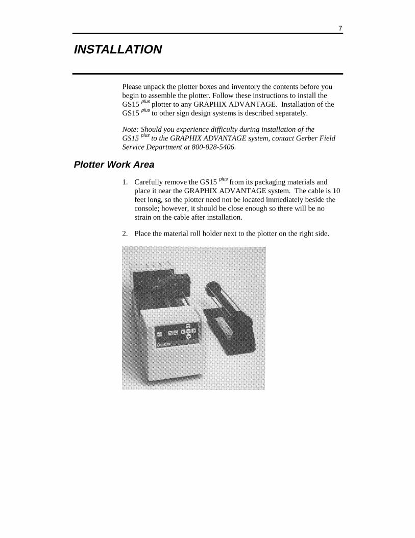
Plotter Work Area
1. Carefully remove the GS15 plus from its packaging materials and place it near the GRAPHIX ADVANTAGE system. The cable is 10 feet long, so the plotter need not be located immediately beside the console; however, it should be close enough so there will be no strain on the cable after installation.
2. Place the material roll holder next to the plotter on the right side.

8 GS15 plus
Connect to the Plotter
CAUTION: Be sure power is turned off and the power cord is unplugged at both the GRAPHIX ADVANTAGE and the plotter.
1. Insert the 9-pin connector at the end of the RS-232 cable into the 9-pin RS-232 connector on the back of the GRAPHIX ADVANTAGE. This connector is normally labeled Plotter or COM Port 2.
2. Carefully align all pins. Use the connector thumb screws to secure the cable to the system.
3. Insert the 25-pin connector at the end of the RS-232 cable into the 25-pin RS-232 connector on the back of the plotter.
4. Carefully align all pins. Secure the cable to the plotter with the connector thumb screws.
Note: If a plotter is already installed in the PLOTTER port on the GRAPHIX ADVANTAGE, use the TABLET port to install a second plotter.
Communication Parameters
If you are connecting the GS750 plus to a system other than the GRAPHIX ADVANTAGE, the plotter uses these RS-232 communication parameters:
Communication Parameters
9600 Baud
No Parity
8 Data Bits
1 Stop Bit
Xon/Xoff Flow Control
Installation 9
The plotter has a 25DB female connector with these pin assignments:
Pin Signal
2 Tx
3 Rx
4 RTS
5 CTS
7 Sig Gnd
All other pins are not connected.
Power Cords
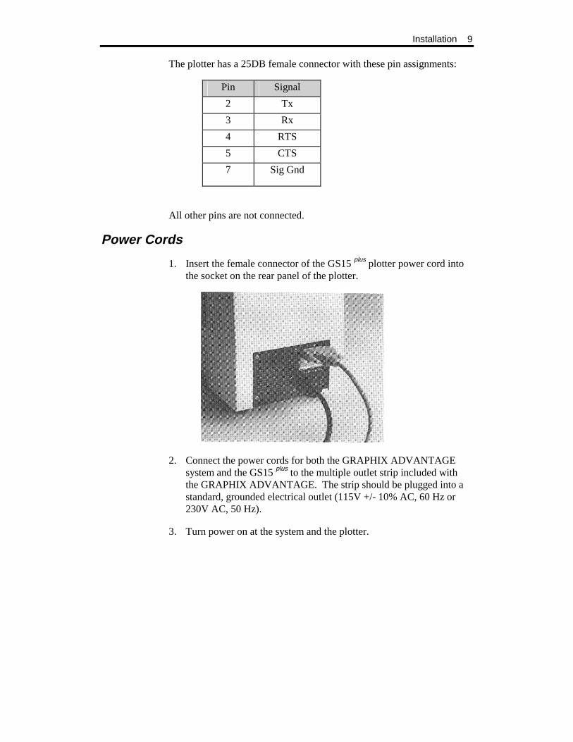
1. Insert the female connector of the GS15 plus plotter power cord into the socket on the rear panel of the plotter.
2. Connect the power cords for both the GRAPHIX ADVANTAGE system and the GS15 plus to the multiple outlet strip included with the GRAPHIX ADVANTAGE. The strip should be plugged into a standard, grounded electrical outlet (115V +/- 10% AC, 60 Hz or 230V AC, 50 Hz).
3. Turn power on at the system and the plotter.

10 GS15 plus
CAUTION: When the power is on, never try to manually move the carriage, move the drum, rotate the tool, or force the tool up or down. Attempting to manually move the GS15 plus in any axis of movement while the power is on may damage the plotter.
Power-Up Sequence
When the GS15 plus is turned on, the following sequence occurs:
1. A short beep sounds, the Power light comes on, and the RUN CONT, RUN SING, and SWIVEL KNIFE lights blink.
2. As the GS15 plus performs self-check tests, the lights over the RUN and SWIVEL KNIFE keys flash, and one additional beep sounds.
3. When the self-check is complete, the lights blink and a beep sounds.
4. The plotter goes off-line in tangential knife mode. Only the Power light remains on. This is the initial setting at power-up.
Note: Rapid, continuous beeping and flashing lights may signal a self-check error. See the "Error Conditions" section for more information.
11
SETUP
After connecting the plotter to the GRAPHIX ADVANTAGE, you will use the GSP Setup program in GRAPHIX ADVANTAGE to make the GS15 plus accessible.
Note: When the GS15 plus is used with sign design systems other than GRAPHIX ADVANTAGE, contact the system manufacturer to obtain a driver for the GS15 plus and for setup information.
Plotter Selection
1. Double-click on the GSP Setup icon to open GSP Setup.
2. Click on Setup. The Setup drop-down menu appears.
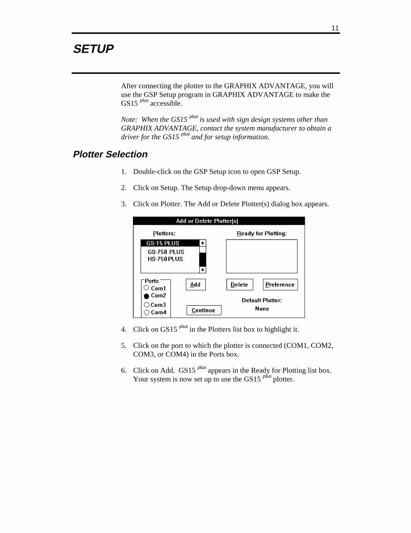
3. Click on Plotter. The Add or Delete Plotter(s) dialog box appears.
4. Click on GS15 plus in the Plotters list box to highlight it.
5. Click on the port to which the plotter is connected (COM1, COM2, COM3, or COM4) in the Ports box.
6. Click on Add. GS15 plus appears in the Ready for Plotting list box. Your system is now set up to use the GS15 plus plotter.

12 GS15 plus
Note: The Default Plotter note in the lower right corner of the dialog box tells you the name of the plotter your jobs will be sent to unless otherwise specified in the Plot program.
7. Click on Continue. The screen will return to the GSP Setup Menu.
8. Double-click on the Control Bar to exit the GSP Setup Menu. The system will return to the GSP GRAPHIX ADVANTAGE program group and you can now access the GS15 plus plotter.
Add Plotters
Multiple plotters can be added to your system. They must be added one by one.
1. Click on the plotter you wish to add from the plotters list box.
2. Click on the port it will be connected to.
3. Click on Add. The highlighted plotter is added to the Ready for Plotting list box.
Note: For each plotter you add, a number is added after the plotter model number (for example, GS 15-1 for the first plotter added, GS 15-2 for the second).
Delete Plotters
To remove plotters from the system:
1. In the Ready for Plotting box, click on the name of the plotter to be deleted.
2. Click on Delete.

Setup 13
Assign Default Plotter
A default plotter can be assigned if more than one plotter is connected to the GRAPHIX ADVANTAGE.
Note: There must be two or more plotter names in the Ready for Plotting box to select a default plotter. If only one plotter is installed to the GRAPHIX ADVANTAGE system, that plotter will automatically be assigned as the default plotter.
1. Highlight the name of the desired default plotter in the Plotters box.
2. Click on Preference.
3. Click on OK. The name of the default plotter selected will appear below the words Default Plotter.
4. Click on Continue. The screen returns to the GSP Setup menu.
5. Double-click on the Control Bar to exit the GSP Setup menu. The system will return to the GSP GRAPHIX ADVANTAGE program group.

15
MATERIALS AND TOOLS
Materials
The GS15 plus uses the same plotting materials as all Gerber plotters. Gerber vinyl products in high performance or intermediate grades are available in translucent, reflective, or metallic finishes and come in a wide range of colors. Also available are direct-cut screenprint stencil, ruby photo film, paint masking material, rubber sandblast stencil material and heat transfer materials. Consult your Gerber distributor for further information about available materials, colors and prices. Always insist on Gerber authorized materials for highest quality results.
To load material
CAUTION: it is recommended that you load material without a tool in the carriage to prevent damaging the knife blade.
1. Slide the roll of material to be used onto the roll holder. Pull the end of the material away from and over the top of the roll holder toward the plotter.
CAUTION: when power is on, the carriage spindle must be moved only by using the slew keys. attempts to manually move the plotter drum, rotate or force the tool up or down will damage the plotter.
CAUTION: While power is off, center the carriage by gently pushing toward the center of its travel. Take care to move the carriage slowly and firmly by gripping the right end of the carriage housing, not by gripping the carriage spindle.
CAUTION: Do not use the way shafts to lift or turn the GS15 plus. This will damage the system and reduce plotting accuracy.

16 GS15 plus
2. Center the carriage spindle preferably by using the slew keys (see "Front Panel" section) or manually, with certain precautions as outlined here. Be sure that the carriage spindle is not located at either extreme end of its travel and that both ends of the rubber drum can be reached easily.
3. Open the bail arms at either end of the drum by pulling them up and away from the drum.
4. Using the slew (arrow) keys, rotate the drum until three closely spaced pins are visible. These three sprocket pins are used to align the material.
Materials and Tools 17
To feed and align material
1. Feed material under the black cam shaft and over the rubber drum. See the illustration below.
2. Place the holes in the material over the sliding sprocket pins first. Match the three closely spaced sprocket pins and holes.
3. Slide the material and the sliding sprocket to reach the fixed sprocket and place the material over these sprocket pins.
4. Center the bail arms over the sprockets. Move the adjustable bail arm at the rear of the plotter slightly forward or backward to accommodate small differences in the material width. Securely close the front bail arm first and then the rear bail arm.
18 GS15 plus
HELPFUL HINTS
! When you change materials, open the bail arms and roll the material back onto the roll. Tape the ends securely to prevent the roll from unraveling.
! Before unrolling vinyl for a job, determine how much material you need. Check the length of the longest line in the job, or the width of an automatically laid out sign or digitized design. Remember that if you are plotting in the Axis Swap mode, you need to consider the height of the job rather than its width.
! The most practical way to unroll material for a job is to use the slew keys on the plotter. It is best to unroll more than enough material, rather than "just enough," in case your estimate is not accurate. You may also pull material from the roll by hand. This may be the simplest method if you are plotting relatively small jobs.
! When you have advanced enough material for the job, feed it back through the plotter, or otherwise position it appropriately according to the tool start position selected from GRAPHIX ADVANTAGE. If you have a large quantity of material piling up on the table, be sure to arrange the material in loose accordion folds so it can feed easily. Make sure the material is positioned to feed straight into the plotter rather than at an angle.
Materials and Tools 19
Tool Force Dial
The tool force dial on the front of the housing indicates the tool force setting and the amount of tool force, or pressure, that is applied to the tool during operation. This pressure ensures uniform cuts and pen lines. Tool force can be adjusted by turning the small knob on the end of the tool force housing, as shown in the illustration below.
SETTINGS
The Plotter User Reference Card at the end of this manual lists approximate tool force settings. Be sure to refer to this list of settings when changing materials or applications. Below are some initial suggestions:
! For drawing, start with a tool force setting of about .5. If your pen does not make a clear dark line, you may wish to increase the tool force setting.
! For pouncing, start with a setting between 5 and 6.
! When cutting regular vinyl in tangential knife mode, try a tool force setting of 1.
! When cutting regular vinyl in swivel knife mode, set the tool force setting at 1. The swivel knife will not pivot at corners and will begin to cut through the material if the pressure is set too high.
! Heavier material, such as reflective vinyl, requires increased tool force settings.

20 GS15 plus
! Worn blades require increased tool force settings.
! Before cutting, refer to the Plotter User Reference Card at the back of this manual for suggested tool force settings for different tools and materials. Set the tool force accordingly. If you find that different tool force settings produce more satisfactory results with your particular system, tools, and materials, be sure to mark the preferred settings on your card for future use.
ADJUSTMENTS
Several factors affect tool force and require setting changes:
! Type of material — See Plotter User Reference Card.
! Knife mode and tool — Drawing, pouncing, and cutting, knife mode, and blade angle all affect the tool force setting
! Blade wear — Increase tool force after several thousand cuts.
Gerber recommends experimenting with tool force settings as well as keeping a logbook of the settings. Refer to the Plotter User Reference Card for guidelines.
21
TOOLS AND TOOL HANDLING
Storage
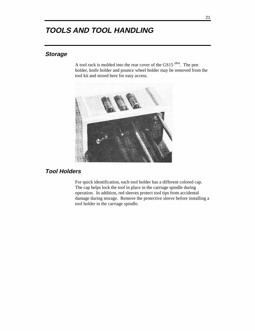
A tool rack is molded into the rear cover of the GS15 plus. The pen holder, knife holder and pounce wheel holder may be removed from the tool kit and stored here for easy access.
Tool Holders
For quick identification, each tool holder has a different colored cap. The cap helps lock the tool in place in the carriage spindle during operation. In addition, red sleeves protect tool tips from accidental damage during storage. Remove the protective sleeve before installing a tool holder in the carriage spindle.
22 GS15 plus
Pen Holder and Pens
The pen holder is shipped with a black pen installed. After loading the plotting paper, install the pen holder in the carriage spindle as follows:
To install the pen holder
1. Select the pen holder with pen installed from the tool rack molded in the rear cover.
2. A plastic lift washer is used to reduce friction between the tool holder and the lift fork of the carriage spindle during operation. There should be one installed on the pen holder. If not, slip a lift washer from the tool kit over the barrel and slide the washer to the top of the holder.
3. Drop the pen holder into the carriage spindle. A slot, or keyway, in the barrel of the pen holder ensures proper orientation. If necessary, rotate the pen holder until it drops completely into the carriage spindle.
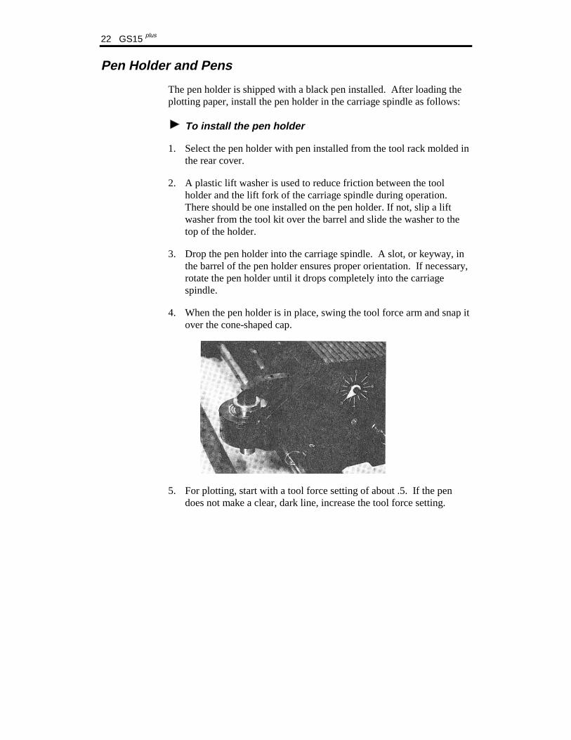
4. When the pen holder is in place, swing the tool force arm and snap it over the cone-shaped cap.
5. For plotting, start with a tool force setting of about .5. If the pen does not make a clear, dark line, increase the tool force setting.
Tools and Tool Handling 23
PEN REPLACEMENT
Spare pens in blue and red are included in the tool kit. Additional pens are available through a Gerber distributor.
To replace a pen
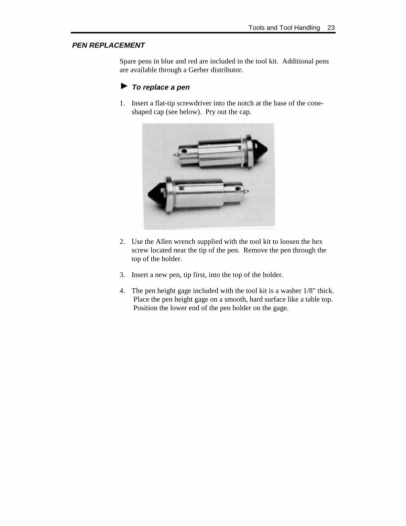
1. Insert a flat-tip screwdriver into the notch at the base of the cone-shaped cap (see below). Pry out the cap.
2. Use the Allen wrench supplied with the tool kit to loosen the hex screw located near the tip of the pen. Remove the pen through the top of the holder.
3. Insert a new pen, tip first, into the top of the holder.
4. The pen height gage included with the tool kit is a washer 1/8" thick. Place the pen height gage on a smooth, hard surface like a table top. Position the lower end of the pen holder on the gage.

24 GS15 plus
5. Push down on the upper end of the pen until the point just touches the table surface.
6. Use the Allen wrench to tighten the set screw near the tip of the pen. Do not over-tighten the set screw or the pen could be crushed.
7. Replace the cap in the barrel.
Tools and Tool Handling 25
Pounce Wheel Holder
Pouncing is a technique used to create an outline for a sign that will later be hand-painted. Pouncing can also be used to align vinyl letters on a large job. The pounce wheel is designed to pounce (perforate) holes either perfectly aligned or off-center to the direction of travel.
CAUTION: The pounce wheel may be used only in tangential knife mode. Pouncing in swivel knife mode will tear the paper.
ALIGNED HOLES
There are two keyway slots on the barrel of the pounce wheel holder. The standard keyway aligns the pounce with the drum axes. Use this position to produce small holes in lightweight paper or for light dusting applications.
OFF-CENTER HOLES
The second keyway holds the tool at 11 degrees off-center to the direction of tool travel. Using the pounce wheel in the angled position causes the points to drag slightly as the wheel moves forward. This produces larger, slightly elongated holes suited for heavy or clay-coated paper and for bold dusting applications.
PLOTTER SPEED
In the straight (aligned) position, the pounce wheel works best at reduced plotter speeds. The angled (off-center) position produces distinct holes at any plotting rate up to full speed. See the GRAPHIX ADVANTAGE Reference for more information on controlling the plotter speed.
POUNCE WHEEL HOLDER INSTALLATION
To install the pounce wheel holder
1. Select the pounce wheel holder from the molded tool rack in the rear cover.
26 GS15 plus
2. A plastic lift washer is used to reduce friction between the tool and the lift fork of the carriage spindle during operation. There should be one installed on the pounce wheel holder. If not, slip a lift washer from the tool kit over the barrel and slide the washer to the top of the holder.
3. Hold the pounce wheel holder upright over the carriage spindle. Rotate the barrel until the desired keyway is oriented above the protruding key inside the carriage spindle. Lower the pounce wheel holder into the carriage spindle.
4. When the pounce wheel holder is in place, swing the tool force arm and snap it over the cone-shaped cap.
5. Check the pounce wheel position by looking under the carriage to make sure the wheel is oriented at the desired angle.
6. Pouncing generally requires higher tool force settings than drawing or cutting. To begin, set the tool force dial between 5 and 6. Adjust, if necessary, for paper thickness or desired hole size. Reduce plotter speed if pouncing small holes.
POUNCE WHEEL REPLACEMENT
One pounce wheel supplied is installed in the tool holder, and a spare is included in the tool kit.
To replace the pounce wheel
1. Using the Allen wrench from the tool kit, remove the hex screw that serves as the wheel's axle.
2. Remove the old wheel. Position the new wheel in the holder.
3. Slide hex screw through holder and wheel (as an axle) and tighten.

Tools and Tool Handling 27
Knife Holder and Blades
Gerber blades are extremely wear-resistant. In testing, over 10,000 one-inch letters were cut using a single blade before testing was discontinued with the blade still cutting satisfactorily. Other blade manufacturers have attempted, unsuccessfully, to duplicate this cutting precision and durability. Gerber warrants cutting quality of the GS15 plus only when Gerber blades are used.
BLADE WEAR
The knife blade will dull slightly after cutting thousands of characters. Blade wear is always a gradual change. Adjusting tool force will extend blade life for a period of many days and even weeks of use.
BLADE DAMAGE
CAUTION: Carbide blades are brittle and can be ruined by the slightest chip of the cutting tip.
Because they are ground to a controlled length, the blades cannot be resharpened. A sudden decline in cutting quality indicates that the knife blade is chipped. Replace and discard any chipped blade.
28 GS15 plus
KNIFE HOLDER INSTALLATION
The GS15 plus comes with two different types of knife holder:
! Swivel Knife - Used to cut all but the thickest materials, such as sandblast stencil, at high speed.
! Tangential Knife - Used to cut all materials, including sandblast stencil. The tangential knife can be used with either 30°, 45° or 60° blades.
To install a knife holder
1. Load vinyl or other material.
2. Select the knife holder that matches the knife mode you want to use.
3. A plastic lift washer is used to reduce friction between the tool holder and the lift fork of the carriage spindle during operation. There should be one installed on the knife holder. If not, slip a lift washer from the tool kit over the barrel and slide the washer to the top of the holder.
CAUTION: Carefully install the knife holder, taking care not to strike the tip of the blade against the bore of the carriage spindle.
4. A slot, or keyway, in the barrel of the knife holder ensures proper orientation. If necessary, rotate the knife holder until it drops completely into the carriage spindle.
5. When the knife holder is in place, swing the tool force arm and snap it into place over the cone-shaped cap.
6. Select a tool force setting appropriate for material and blade. Approximate tool force settings for cutting other vinyl materials are listed in the following chart. (See Plotter User Reference Card.)
Tools and Tool Handling 29
Suggested Tool Force Settings
Material Recommended Starting Tool Force
Tangential Knife Blade
Swivel Knife Blade
Controltac 180 Delux 210 Gold/Silver Dusted Crystal 210 .05-1 30 ° GS 35° Florescent 210 Scotchcal™ 220 Translucent 230 Gerber Cal® Gerber IP Plus GerberMask™ I & II 1 30° GS 35° Heat Transfer Flock Hot Split Plastisol Metalized Polyester Screen Print .05 30° GS 35° Static Cling Sandblast 521 4-5 45° or 60° Sandblast 522
To determine if adjustment of the tool force setting is required, consider that:
! The weed should peel off easily. ! There should be no cuts through the backing material.
When in swivel knife mode, use the minimum tool force setting that cuts satisfactorily. Too much force will reduce edge quality.
30 GS15 plus
BLADE REPLACEMENT
Five carbide knife blades are included with the GS15 plus:
! one installed in the tangential knife holder ! two tangential knife spares ! one installed in the swivel knife holder ! one swivel knife spare
Extra blades and special angled blades for sandblast vinyls are available from your Gerber distributor.
WARNING: The blade is very sharp. Take care when handling the knife holder and blade.
CAUTION: Blades are fragile and can break. Do not use tools to handle new blades.
The replacement procedures for the tangential and swivel knife blades are different.
To replace the tangential knife blade
1. Loosen the hex screw with the Allen wrench from the tool kit.
2. Carefully remove the old blade.
3. Install the replacement blade in the slot provided, not riding up on either edge.
Gently seat the flat end of the blade against the pin stop with the blade point toward the center of the tool. Retighten the hex screw.
Tools and Tool Handling 31
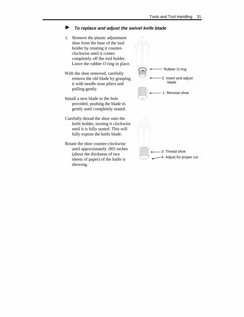
To replace and adjust the swivel knife blade
1. Remove the plastic adjustment shoe from the base of the tool holder by rotating it counter-clockwise until it comes completely off the tool holder. Leave the rubber O ring in place.
With the shoe removed, carefully remove the old blade by grasping it with needle nose pliers and pulling gently.
Install a new blade in the hole provided, pushing the blade in gently until completely seated.
Carefully thread the shoe onto the knife holder, turning it clockwise until it is fully seated. This will fully expose the knife blade.
Rotate the shoe counter-clockwise until approximately .005 inches (about the thickness of two sheets of paper) of the knife is showing.
1. Remove shoe
3. Thread shoe
4. Adjust for proper cut
Rubber O ring
2. Insert and adjustblade


33
OPERATION
Power-Up
When the GS15 plus is turned on, the following sequence occurs:
1. A short beep sounds, the Power light comes on, and the RUN CONT, RUN SING, and SWIVEL KNIFE lights blink.
2. As the GS15 plus performs self-check tests, the lights over the RUN and SWIVEL KNIFE keys flash, and one additional beep sounds.
3. When the self-check is complete, the lights blink and one beep sounds.
4. The plotter goes off-line in tangential knife mode. Only the Power light remains on. This is the initial setting at power-up.
Note: Rapid, continuous beeping and flashing lights may signal a self-check error. See the "Error Conditions" section for more information.
34 GS15 plus
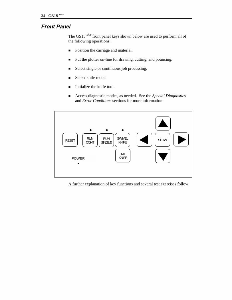
Front Panel
The GS15 plus front panel keys shown below are used to perform all of the following operations:
! Position the carriage and material.
! Put the plotter on-line for drawing, cutting, and pouncing.
! Select single or continuous job processing.
! Select knife mode.
! Initialize the knife tool.
! Access diagnostic modes, as needed. See the Special Diagnostics and Error Conditions sections for more information.
A further explanation of key functions and several test exercises follow.
RESET RUNCONT
RUNSINGLE
SWIVELKNIFE
SLOW
INITKNIFEPOWER
Operation 35
SLEW KEYS
Use the left and right slew keys to unroll material before plotting, to position the tool for plotting, and to position the carriage and material between jobs.
Press the up or down slew keys to move the carriage between the rear and the front of the plotter.
Press the left or right slew keys to rotate the drum and feed material through the plotter or back toward the roll holder.
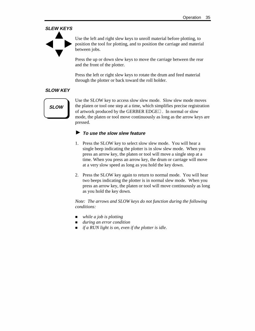
SLOW KEY
Use the SLOW key to access slow slew mode. Slow slew mode moves the platen or tool one step at a time, which simplifies precise registration of artwork produced by the GERBER EDGE . In normal or slow mode, the platen or tool move continuously as long as the arrow keys are pressed.
To use the slow slew feature
1. Press the SLOW key to select slow slew mode. You will hear a single beep indicating the plotter is in slow slew mode. When you press an arrow key, the platen or tool will move a single step at a time. When you press an arrow key, the drum or carriage will move at a very slow speed as long as you hold the key down.
2. Press the SLOW key again to return to normal mode. You will hear two beeps indicating the plotter is in normal slew mode. When you press an arrow key, the platen or tool will move continuously as long as you hold the key down.
Note: The arrows and SLOW keys do not function during the following conditions:
! while a job is plotting ! during an error condition ! if a RUN light is on, even if the plotter is idle.
SLOW
36 GS15 plus
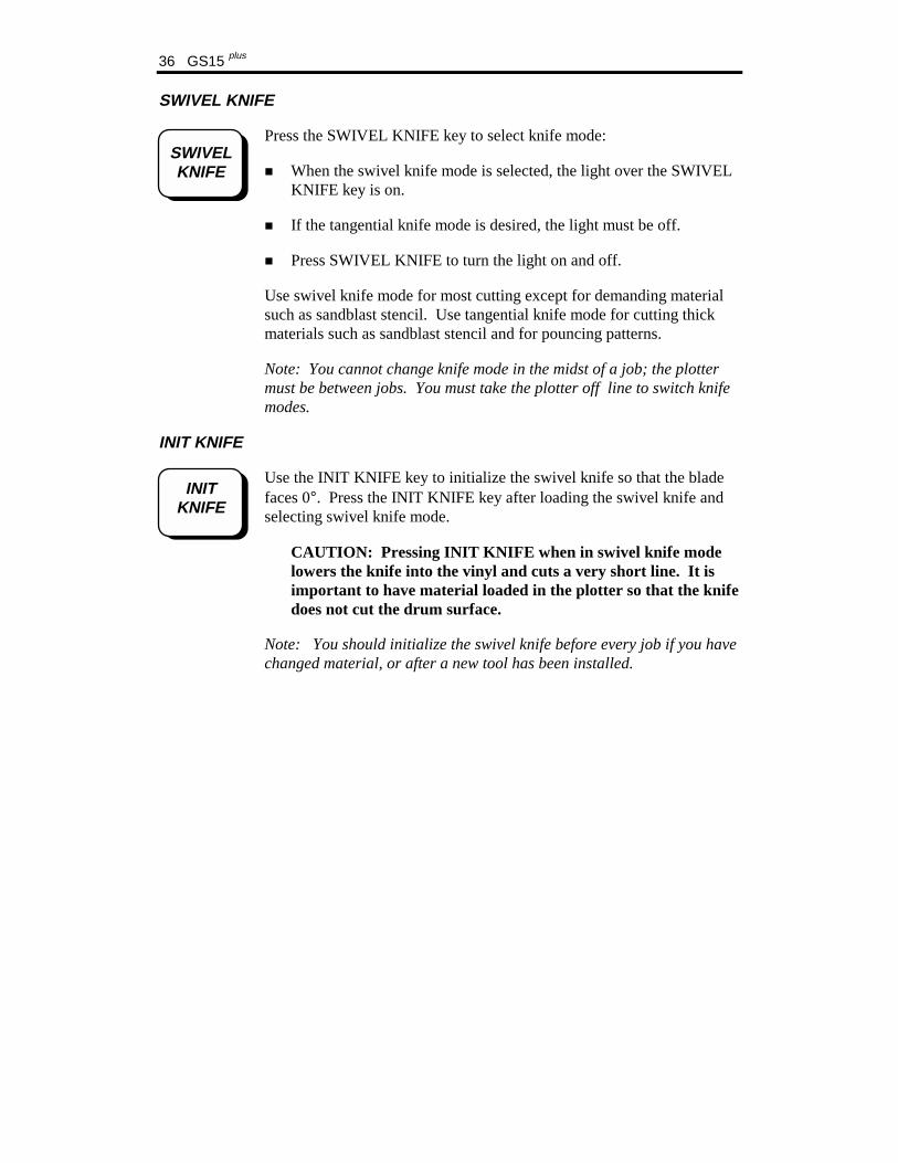
SWIVEL KNIFE
Press the SWIVEL KNIFE key to select knife mode:
! When the swivel knife mode is selected, the light over the SWIVEL KNIFE key is on.
! If the tangential knife mode is desired, the light must be off.
! Press SWIVEL KNIFE to turn the light on and off.
Use swivel knife mode for most cutting except for demanding material such as sandblast stencil. Use tangential knife mode for cutting thick materials such as sandblast stencil and for pouncing patterns.
Note: You cannot change knife mode in the midst of a job; the plotter must be between jobs. You must take the plotter off line to switch knife modes.
INIT KNIFE
Use the INIT KNIFE key to initialize the swivel knife so that the blade faces 0°. Press the INIT KNIFE key after loading the swivel knife and selecting swivel knife mode.
CAUTION: Pressing INIT KNIFE when in swivel knife mode lowers the knife into the vinyl and cuts a very short line. It is important to have material loaded in the plotter so that the knife does not cut the drum surface.
Note: You should initialize the swivel knife before every job if you have changed material, or after a new tool has been installed.
SWIVELKNIFE
INITKNIFE

Operation 37
RUN SINGLE
Plot
Use RUN SINGLE to plot a single job. This plot mode allows the operator to reposition material between jobs and/or to pen plot using paper before cutting vinyl. RUN SINGLE may be used with either swivel knife mode or tangential knife mode.
1. Press SWIVEL KNIFE to select a knife mode. (For swivel knife mode, the light over the SWIVEL KNIFE key is on. For tangential knife mode, the light is off.
2. Press RUN SINGLE. The light over the RUN SINGLE key comes on and the GS15 plus plots a single job. If other plot files are received from the GRAPHIX ADVANTAGE while the first job plots, then a waiting list, or queue, of these jobs is created.
3. The GS15 plus returns to the off-line status after the job plots. It remains in the knife mode selected.
4. The GS15 plus waits for the operator to press the RUN SINGLE key again to plot the next job. If other jobs are lined up in the queue, the green lights above the two RUN keys will flash.
Controlled Stop
Use RUN SINGLE (or RUN CONT) to pause plotting and check the current job.
1. Press the currently selected RUN key during a job to pause the job. The GS15 plus stops the job at the next logical break in the program.
Note: Do not use slew keys or orientation for the current job will be lost.
2. Press either RUN key to resume plotting at the exact same point.
RUNSINGLE
38 GS15 plus
Single Plot Exercise
1. Turn on the GS15 plus. Load plotting paper, test the pen manually, install the pen holder, and set the tool force to .5.
2. Using the slew keys, position the carriage spindle approximately 1" from the front edge of the plotting paper. Also, be sure that there are several inches of paper extending past the carriage spindle and to the left of the plotter.
3. Send a plot file to the GS15 plus plotter.
4. Press the RUN SINGLE key to plot the test exercise.
RUN CONT
Use RUN CONT to access the continuous plotting mode and maximize the plotter's productivity.
To plot in continuous mode
1. Select either swivel or tangential knife mode by pressing the SWIVEL KNIFE key. When swivel knife mode is selected, the light above the SWIVEL KNIFE key is on.
2. Press RUN CONT. The light above the RUN CONT key comes on and the GS15 plus plots one job after the other without waiting for user prompting between the jobs.
3. The GS15 plus creates a waiting list, or queue, of jobs to be plotted. When one job finishes plotting, the next job waiting in the queue begins immediately.
4. When all jobs in the queue are plotted, the GS15 plus remains on-line until the operator presses either RUN key or the RESET key to return to off-line status.
RUNCONT

Operation 39
Controlled Stop
Use RUN CONT (or RUN SINGLE) to pause plotting and check the current job.
To stop a continuous mode plot
1. Press either RUN key. The GS15 plus stops the plot at the next logical break in the program. Do not use slew keys or orientation for the current job will be lost.
2. Press either RUN key to resume plotting at the exact same point.
Continuous Plot Exercise
1. Turn on the GS15 plus. Load plotting paper, install the pen holder, and set the tool force to .5.
2. Select either swivel or tangential knife mode by pressing the SWIVEL KNIFE key. When swivel knife mode is selected, the light above the SWIVEL KNIFE key is on.
3. Using the slew keys, position the carriage spindle approximately 1" from the front edge of the plotting paper. Be sure that there are several inches of paper extending past the carriage spindle and to the left of the plotter.
4. Prepare two plot files. If using a GRAPHIX ADVANTAGE to prepare the files, in the Plot Program choose a left Start Position and a right End Position for both plots before sending them to the plotter. This will prevent the files from plotting on top of each other. If using another layout program, be sure to position the files so they will not plot on top of each other.
Note: Entering an X,Y pre-position in the Plot Program is another way to be sure that plots done in the RUN CONT mode will not plot on top of each other. (See GRAPHIX ADVANTAGE Reference.)
5. Press the RUN CONT key. Both jobs will plot without a pause between them.

40 GS15 plus
RESET
Use the RESET key to stop plotter operation in case of emergency, to clear error signals, and to access Special Diagnostics.
To cause an emergency stop
Press the RESET key while a job is plotting. The following sequence occurs:
1. GS15 plus operation stops immediately.
2. The current job is cleared. All other jobs in the queue remain intact.
3. The GS15 plus returns to off-line status, as at power-up.
To clear an error signal
Press the RESET key to clear an error (steady tone and flashing lights) after a power-up or plotting failure. (See the "Error Conditions" section.)
To access diagnostics
Hold the RESET key at power-up to access additional diagnostics. (See the "Special Diagnostics" section.)
RESET

41
SPECIAL DIAGNOSTICS
In addition to the self-check tests that are part of the power-up sequence, the GS15 plus plotter can perform other special diagnostics. The steps to access these diagnostics and their functions are outlined below.
To access special diagnostics
1. Hold down the RESET key during power-up.
2. When a steady tone sounds, release the RESET key. There will be two beeps followed by three beeps as the self-check tests are completed. Then the lights above the RUN CONT and RUN SINGLE keys will alternate. These alternating lights mean that RESET was held at power-up and that a special diagnostic can now be performed.
3. Access one of the special diagnostics described next by pressing the slew key noted in the description.
Note: Only one special diagnostic can be accessed at each power-up sequence. To access another diagnostic, turn the plotter power off and then on again (as described above).

42 GS15 plus
Diagnostic Options
The following diagnostics are available:
! RS-232 Loop Back – Press the up arrow key to access. Use to check internal workings of the communications hardware. Beeps indicate a communications error. (A special loop-back test connector is needed for this test. See your Gerber distributor.)
! Wagon Wheel Test Plot − Press the left arrow key to access. Used to check X,Y,Z axes in plot mode and to verify operation after adjustments are made.
! Square/Circle Test Plot − Press the SLOW key. Use to check X, Y, Z, theta axes in cut mode and to verify operation after adjustments are made.
! X08 Cut Test - Press the down arrow key to access. Use to test cut quality.
If the plotter consistently fails a special diagnostic, contact Gerber Field Service Department at 800-828-5406, or fax at 203-645-2448.
Special Diagnostics 43
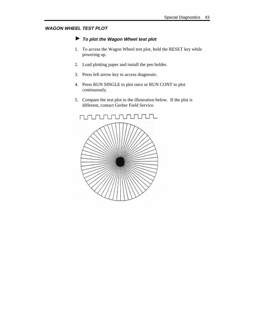
WAGON WHEEL TEST PLOT
To plot the Wagon Wheel test plot
1. To access the Wagon Wheel test plot, hold the RESET key while powering up.
2. Load plotting paper and install the pen holder.
3. Press left arrow key to access diagnostic.
4. Press RUN SINGLE to plot once or RUN CONT to plot continuously.
5. Compare the test plot to the illustration below. If the plot is different, contact Gerber Field Service.

44 GS15 plus
SQUARE/CIRCLE TEST PLOT
To plot the Square/Circle test plot
1. To access the Square/Circle test plot, hold the RESET key while powering up.
2. Load vinyl and install the knife holder.
3. Press SLOW key to access diagnostic.
4. Press RUN SINGLE to plot once or RUN CONT to plot continuously.
5. Compare the test plot to the illustration below. If the plot is different, contact Gerber Field Service.

Special Diagnostics 45
X08 CUT TEST
To plot the X08 cut test
1. To access the X08 cut test plot, hold the RESET key while powering up.
2. Load vinyl and install the knife holder.
3. Press the down arrow.
4. Press RUN SINGLE to plot once or RUN CONT to plot continuously.
5. Compare the test plot to the illustration below. If the plot is different, contact Gerber Field Service.


47
ERROR CONDITIONS
The GS15 plus is programmed to detect several mechanical/electrical error conditions at power-up or during operation. When an error condition occurs, the plotter will turn off power to the stepper motors, flash the RUN lights, and sound a steady tone.
To determine the error condition that stopped plotter operation, follow these steps.
1. Press the RESET key to clear the error signal (flashing lights and steady tone).
2. Press the RUN SINGLE key to display the error code number. The RUN lights flash the same number of times as the error number (once for Error 1, twice for Error 2, etc.). A short beep indicates the end of the error message. Press the RUN SINGLE key again to repeat the message, if desired.
3. Press the RESET key to clear the error display mode and return to the initial off-line status.

48 GS15 plus
ERROR CODES
The error code numbers and suggested operator responses are listed below. Error code numbers are also listed on the User Reference Card.
Error Number
Description
Operator Response
1 Program checksum failure Try power-up again.
2 RAM memory failure Try power-up again.
3 RS-232 test failure Try power-up again.
4 Illegal plot data command Check plot data; resubmit job.
5 Corrupt data Check plot data; resubmit job.
6 Buffer overflow Contact Gerber Field Service.
7 UART error Only occurs as part of self-test; try power-up again.
8 *Z axes lock time-out Power-up again, holding RESET key
9 Z axis error Turn off system; check connectors.
10 Theta home failure Turn off system; check connectors
*Error code occurs in Special Diagnostic mode, if axes remain locked more than 30 minutes.
If the plotter consistently fails the self-check tests, contact Gerber Field Service Department at 800-828-5406, or fax at 203-645-2448.
49
SERVICE AND MAINTENANCE
This section includes instructions for routine cleaning and lubrication, fuse replacement, and adjustments to keep the GS15 plus plotter in good working order.
Cleaning and Lubrication
Routine cleaning and lubrication should be done monthly or after every 160 hours of use, whichever occurs first. Isopropyl alcohol should be used to clean dirty parts.
Note: When alcohol is used, lubricate the parts immediately to prevent corrosion.
Use a light oil such as 3-in-1
Oil for all lubrication, except as noted.
TOOL HOLDERS AND CARRIAGE SPINDLE BORE
Note: The spindle bore should be cleaned daily.
CAUTION: Do not use oil to lubricate tool holders or spindle bore.
There is a very close fit between the pen, knife and pounce wheel holders and the carriage spindle bore. Any dirt or build-up in the bore or on the tool holder restricts motion and can produce inconsistent results.
1. Once a day clean the spindle bore and tool holders with isopropyl alcohol using a clean, dry, lint-free cloth on the tool holders and a clean, dry cotton swab in the bore.
2. Wipe the tool spindle with a soft, lint-free, dry cloth. Dust, hair, silicon, and other debris can greatly affect tool performance and letter quality.

50 GS15 plus
CARRIAGE AND BALL BUSHING
1. Use a lint-free cloth and alcohol to clean any dust or debris from the front way, drive shaft, cam shaft and rear way. Rotate the cam shaft and rear way (the front way does not turn) and move the carriage spindle for access to the entire length of these shafts.
2. The rear way and front way should be given a light coat of oil. This is best done by applying with a lint-free cloth.
Service and Maintenance 51
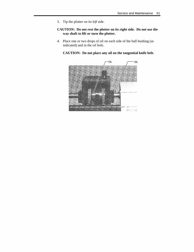
3. Tip the plotter on its left side.
CAUTION: Do not rest the plotter on its right side. Do not use the way shaft to lift or turn the plotter.
4. Place one or two drops of oil on each side of the ball bushing (as indicated) and in the oil hole.
CAUTION: Do not place any oil on the tangential knife belt.

52 GS15 plus
SPROCKETS AND BAIL ARMS
1. Inspect the teeth of the drum sprockets for adhesive buildup from the use of vinyl films.
2. Use a small stiff brush (such as a toothbrush) dipped in alcohol to clean the sprockets.
3. After using alcohol to clean them, immediately dry the sprockets and drum with a lint-free cloth.
4. Place one drop of oil in each pin of the sliding sprocket at the front of the plotter.
5. Slide the sprocket back and forth to work the oil into the bushing.
6. Oil the bail arm pins. Do not oil excessively.
Service and Maintenance 53
Fuse Replacement
Two spare fuses are included with the GS15 plus plotter. The fuse holder is located between the on/off switch and the power cord connector on the rear panel of the plotter.
To replace the fuse
WARNING: turn off power at the plotter and the system and disconnect from the power supply.
1. Unscrew and remove the RS-232 cable from the rear panel of the GS15 plus.
2. Remove the plotter power cord from the socket.
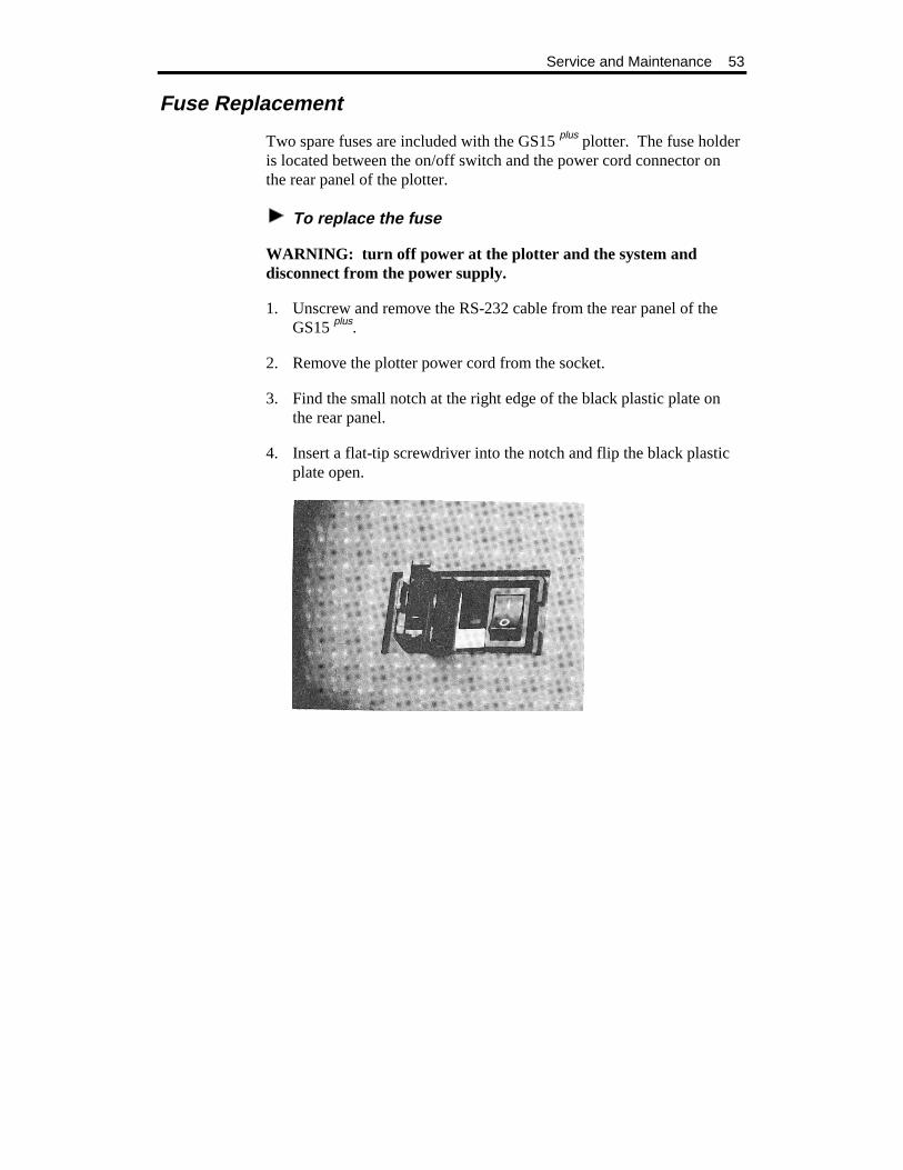
3. Find the small notch at the right edge of the black plastic plate on the rear panel.
4. Insert a flat-tip screwdriver into the notch and flip the black plastic plate open.

54 GS15 plus
5. Pull out the light gray fuse carriers one at a time. Note that each carrier has a white arrow on it and that the arrow points downward (as do the two arrows on the black plastic plate).
6. Examine each fuse. Remove any blown fuse. Install a new fuse of the same type and rating in the same place.
7. Reinsert each carrier, with the arrow pointing downward. Be sure the carriers are inserted all the way. Close the black plastic plate firmly.
8. Reinstall the power cord and the cable connector. Turn the power on at the system and at the plotter.
55
PLOTTER ADJUSTMENTS
The section contains a troubleshooting guide to help identify possible error conditions according to the symptoms displayed and the recom-mended adjustment procedures.
It also contains a brief description of plotter adjustment problems that should be handled by contacting Gerber Field Service Department at 800-828-5406.
Note: Gerber warranties do not cover unauthorized repair. Some service procedures require delicate adjustment of plotter parts. If damage to your GS15 plus plotter results from improper unauthorized service, repair will NOT be covered by any Gerber warranty.
56 GS15 plus
Troubleshooting Guide
This chart of Z Axis (Tool Height) Adjustment symptoms is designed to help identify the possible problem and the probable adjustment procedure.
CAUTION: Turn off GS15 plus plotter and GRAPHIX ADVANTAGE or other sign design system before checking connections or attempting to make any adjustments, unless otherwise directed.
Symptom Recommended Procedure
No power 1. Check power cable and plugs. 2. Check on/off switches. 3. Check fuse.
Poor Performance Perform routine cleaning and lubrication.
Plotter Error Press Reset on the plotter. Verify and resend the job.
Inconsistent Tool/ Material Contact
1. Clean spindle bore and tool holder. 2. Change knife blade. 3. Check for proper Z home. 4. Perform Z Axis Adjustment for Tool Height.
Jagged or Serrated Cutting Edges
1. Replace the knife blade. 2. Check for proper theta home. If improper, do theta
adjustment
Closure Problem Check in this order: 1. Material alignment in sprockets 2. Blade position in knife holder.
If the condition still occurs in NORMAL mode (see GRAPHIX ADVANTAGE Reference), make adjustments in this order:
Y Axis Backlash Adjustment. Drum End Play Adjustment.
If the condition occurs when AXIS SWAP in the GRAPHIX ADVANTAGE is on, perform the X Axis Adjustment.
Plotter Adjustment 57
Z Axis (Tool Height) Adjustment
SYMPTOMS
! The tool does not touch the material or touches only between characters.
! The knife does not cut deeply enough. ! The tool height changes in the middle of a job.
OBJECTIVE
To set the height of the lift fork for consistent contact of tool holder with material.
ADJUSTMENT PROCEDURE
1. Turn off power at the plotter.
2. Adjust the pen using the pen height gage. (See “Pen Holder and Pens”).
3. Install the pen holder in the carriage spindle.
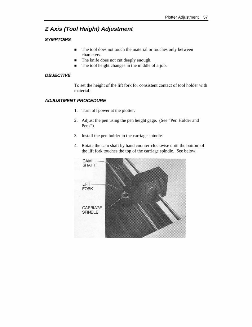
4. Rotate the cam shaft by hand counter-clockwise until the bottom of the lift fork touches the top of the carriage spindle. See below.
58 GS15 plus
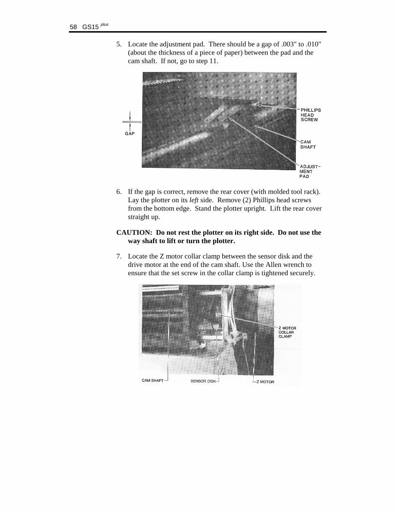
5. Locate the adjustment pad. There should be a gap of .003" to .010" (about the thickness of a piece of paper) between the pad and the cam shaft. If not, go to step 11.
6. If the gap is correct, remove the rear cover (with molded tool rack). Lay the plotter on its left side. Remove (2) Phillips head screws from the bottom edge. Stand the plotter upright. Lift the rear cover straight up.
CAUTION: Do not rest the plotter on its right side. Do not use the way shaft to lift or turn the plotter.
7. Locate the Z motor collar clamp between the sensor disk and the drive motor at the end of the cam shaft. Use the Allen wrench to ensure that the set screw in the collar clamp is tightened securely.
Plotter Adjustment 59
8. Replace the rear cover.
9. Load paper in the plotter.
10. Turn on power. Run a multiple line test plot.
11. If symptoms persist, turn the plotter power off.
12. Rotate the cam shaft by hand until the lift fork is at its lowest position. Continue to rotate the cam shaft in the same direction. Do this until the lift fork starts to lift upward from the spindle. Then rotate the cam shaft back until it is approximately halfway between the highest and lowest positions.
13. At its lowest position, the lift fork should touch the top of the spindle. If the lift fork appears to be adjusted correctly, go to step 17.
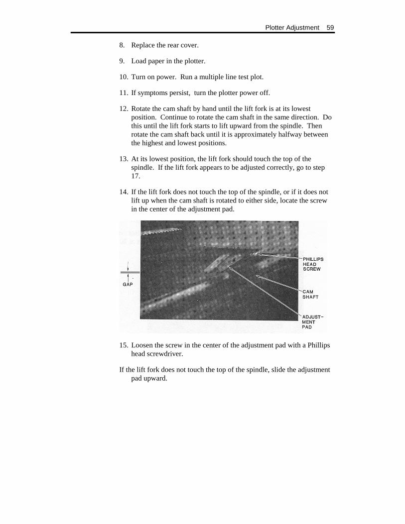
14. If the lift fork does not touch the top of the spindle, or if it does not lift up when the cam shaft is rotated to either side, locate the screw in the center of the adjustment pad.
15. Loosen the screw in the center of the adjustment pad with a Phillips head screwdriver.
If the lift fork does not touch the top of the spindle, slide the adjustment pad upward.

60 GS15 plus
If the lift fork remains touching the spindle when you rotate the cam shaft in either direction from its lowest position, slide the adjustment pad downward.
16. Retighten the adjustment pad screw.
17. Turn off power at the plotter.
18. Power-up the plotter while holding the RESET key. Load paper and install pen holder.
19. Press the left arrow key to access the Wagon Wheel Test Plot. Press either RUN key to plot. Inspect your test plot by comparing to the Wagon Wheel Test Plot illustration.
20. Turn off power at the plotter.
21. Power-up the plotter while holding the RESET key. Load vinyl and install knife holder.
22. Press the SLOW key to access the Square/Circle Test Plot. Press either RUN key to plot. Inspect your test plot by comparing to the Square/Circle Test Plot illustration.
23. If symptoms persist, return to step 1 or contact the Gerber Field Service Department at 800-828-5406, or fax at 203-645-2448.
Plotter Adjustment 61
Theta Axis (Tool Rotation) Adjustment
SYMPTOMS
! Letters have jagged edges. ! Letters have closure problems of less than 1/32". ! The tool loses position in the middle of a job.
OBJECTIVE
To center lift fork over carriage spindle bore; to align tool holder in carriage spindle.
ADJUSTMENT PROCEDURE
1. Remove any tool from the carriage spindle.
2. Turn on power at the plotter.
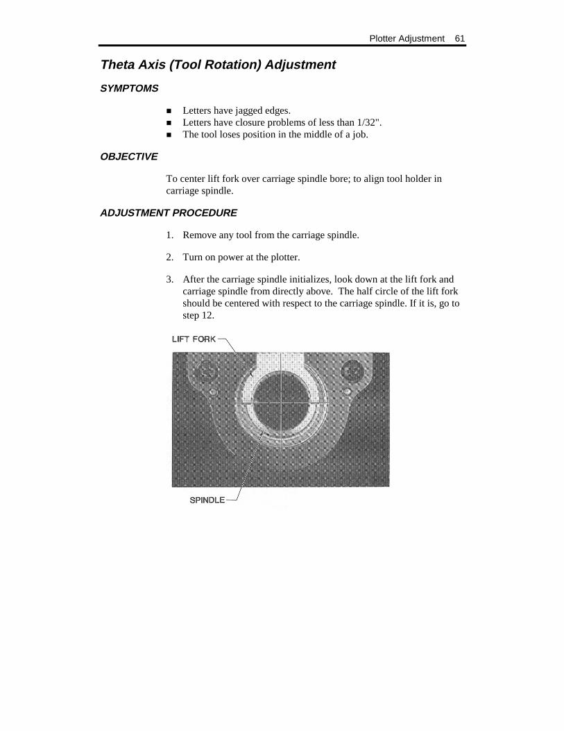
3. After the carriage spindle initializes, look down at the lift fork and carriage spindle from directly above. The half circle of the lift fork should be centered with respect to the carriage spindle. If it is, go to step 12.
62 GS15 plus
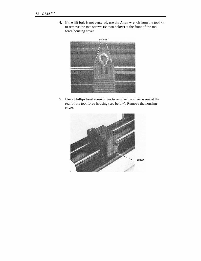
4. If the lift fork is not centered, use the Allen wrench from the tool kit to remove the two screws (shown below) at the front of the tool force housing cover.
5. Use a Phillips head screwdriver to remove the cover screw at the rear of the tool force housing (see below). Remove the housing cover.
Plotter Adjustment 63
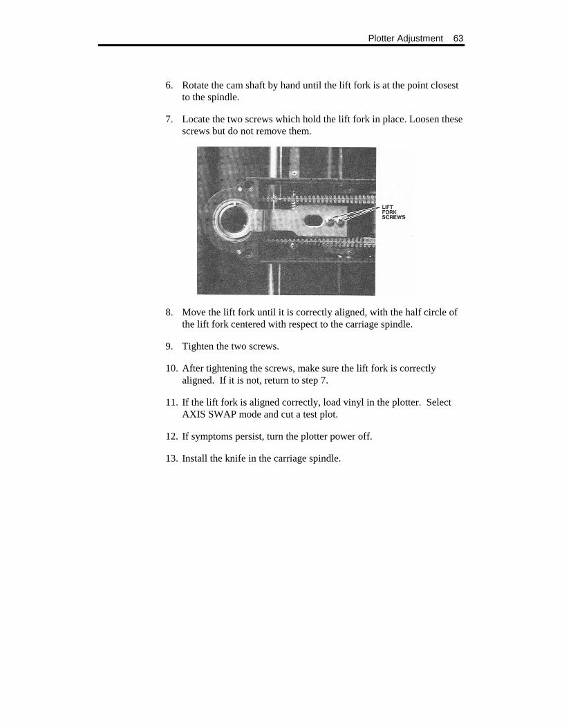
6. Rotate the cam shaft by hand until the lift fork is at the point closest to the spindle.
7. Locate the two screws which hold the lift fork in place. Loosen these screws but do not remove them.
8. Move the lift fork until it is correctly aligned, with the half circle of the lift fork centered with respect to the carriage spindle.
9. Tighten the two screws.
10. After tightening the screws, make sure the lift fork is correctly aligned. If it is not, return to step 7.
11. If the lift fork is aligned correctly, load vinyl in the plotter. Select AXIS SWAP mode and cut a test plot.
12. If symptoms persist, turn the plotter power off.
13. Install the knife in the carriage spindle.

64 GS15 plus
14. Turn on the plotter power.
After the spindle initializes, look under the carriage to note the position of the blade as it sits in the carriage spindle.
! The blade should be parallel with the two forks of the lift fork. ! The tip of the blade should point toward the left side of the plotter. ! The spindle pin should be at 12:00 relative to the front of the plotter.
15. If the tool is aligned correctly, go to step 25.
16. If the tool is not aligned correctly, turn off the plotter power.
17. Remove all tools and materials from the plotter.
18. To remove the rear cover (with molded tool rack), lay the plotter on its left side. Remove (2) Phillips head screws from the bottom edge. Stand the plotter upright. Lift the rear cover straight up.
CAUTION: Do not rest the plotter on its right side. Do not use the way shaft to lift or turn the plotter.
19. Locate the theta motor collar clamp. Use the Allen wrench to ensure that the set screw in the collar clamp is tightened securely.

Plotter Adjustment 65
20. Power on the plotter. The Theta axis is locked for approximately 3 minutes.
21. Locate the rear way collar clamp. Use the Allen wrench to loosen the collar clamp.
22. Rotate the knife holder by hand until the blade is properly aligned, as explained in step 15. Tighten the clamp.
23. Turn the power off to unlock the theta axis.
24. Press and turn the knife holder out of alignment. Power-up the plotter to the normal off-line state. The blade in the knife holder must return to the correct alignment. If not, turn the plotter power off. Return to step 20.
Note: You may need to repeat steps 20 through 24 several times to obtain correct alignment.
25. When the blade is correctly adjusted, power-up the plotter while holding the RESET key. Load paper and install knife holder.
26. Press the down arrow to run the X08 test cut. Press either RUN key to cut. Inspect your test cut.
If symptoms persist, call Gerber Field Service Department at 800-828-5406, or fax at 203-645-2448.
66 GS15 plus
X Axis Belt Adjustment
SYMPTOMS
Text cut in AXIS SWAP mode has closure problems.
OBJECTIVE
To adjust the tension of the X motor belt to produce good letter quality in AXIS SWAP mode.
ADJUSTMENT PROCEDURE
1. Turn the plotter power off.
2. Remove all tools and material from the plotter.
3. Open the bail arms.
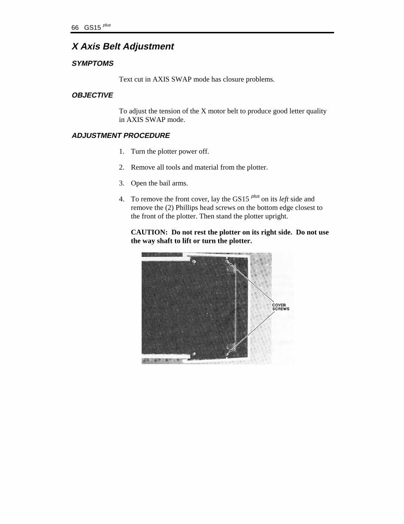
4. To remove the front cover, lay the GS15 plus on its left side and remove the (2) Phillips head screws on the bottom edge closest to the front of the plotter. Then stand the plotter upright.
CAUTION: Do not rest the plotter on its right side. Do not use the way shaft to lift or turn the plotter.
Plotter Adjustment 67
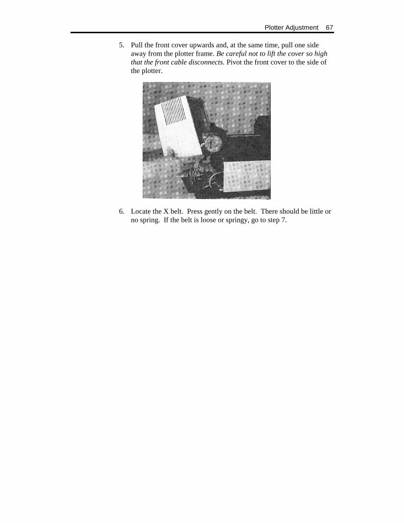
5. Pull the front cover upwards and, at the same time, pull one side away from the plotter frame. Be careful not to lift the cover so high that the front cable disconnects. Pivot the front cover to the side of the plotter.
6. Locate the X belt. Press gently on the belt. There should be little or no spring. If the belt is loose or springy, go to step 7.
68 GS15 plus
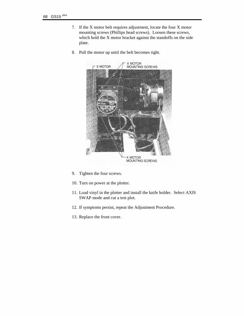
7. If the X motor belt requires adjustment, locate the four X motor mounting screws (Phillips head screws). Loosen these screws, which hold the X motor bracket against the standoffs on the side plate.
8. Pull the motor up until the belt becomes tight.
9. Tighten the four screws.
10. Turn on power at the plotter.
11. Load vinyl in the plotter and install the knife holder. Select AXIS SWAP mode and cut a test plot.
12. If symptoms persist, repeat the Adjustment Procedure.
13. Replace the front cover.

Plotter Adjustment 69
Y Axis Backlash Adjustment
SYMPTOMS
Text cut in NORMAL mode has closure problems.
OBJECTIVE
To adjust the mesh of the jack shaft gear with the Y motor pinion to produce good letter quality in NORMAL mode.
ADJUSTMENT PROCEDURE
1. Turn the plotter power off.
2. Remove all tools and material from the plotter.
3. To remove the front cover, lay the GS15 plus on its side and remove the (2) Phillips head screws on the bottom edge closest to the front of the plotter. Then stand the plotter upright.
70 GS15 plus
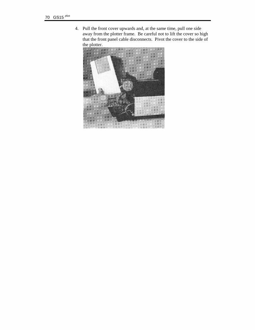
4. Pull the front cover upwards and, at the same time, pull one side away from the plotter frame. Be careful not to lift the cover so high that the front panel cable disconnects. Pivot the cover to the side of the plotter.
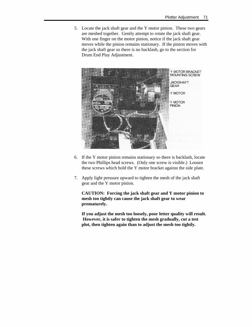
Plotter Adjustment 71
5. Locate the jack shaft gear and the Y motor pinion. These two gears are meshed together. Gently attempt to rotate the jack shaft gear. With one finger on the motor pinion, notice if the jack shaft gear moves while the pinion remains stationary. If the pinion moves with the jack shaft gear so there is no backlash, go to the section for Drum End Play Adjustment.
6. If the Y motor pinion remains stationary so there is backlash, locate the two Phillips head screws. (Only one screw is visible.) Loosen these screws which hold the Y motor bracket against the side plate.
7. Apply light pressure upward to tighten the mesh of the jack shaft gear and the Y motor pinion.
CAUTION: Forcing the jack shaft gear and Y motor pinion to mesh too tightly can cause the jack shaft gear to wear prematurely.
If you adjust the mesh too loosely, poor letter quality will result. However, it is safer to tighten the mesh gradually, cut a test plot, then tighten again than to adjust the mesh too tightly.

72 GS15 plus
8. While holding the motor bracket in place, tighten the two bracket screws.
9. Turn the plotter power on.
10. Load vinyl in the plotter, install the knife holder and cut a test plot.
11. If symptoms persist, return to step 1.
12. Replace the front cover.
Plotter Adjustment 73
Drum End Play Adjustment
SYMPTOMS
! Text cut in NORMAL mode has closure problems. ! Y axis backlash check procedure shows no problem.
OBJECTIVE
To slide the plotter drum and X Axis gear toward each other and clamp them in position to remove end play; to make sure the drum still rotates without binding.
ADJUSTMENT PROCEDURE
1. Turn the plotter power off.
2. Remove all tools and material from the plotter.
3. Open the bail arms to free drum.
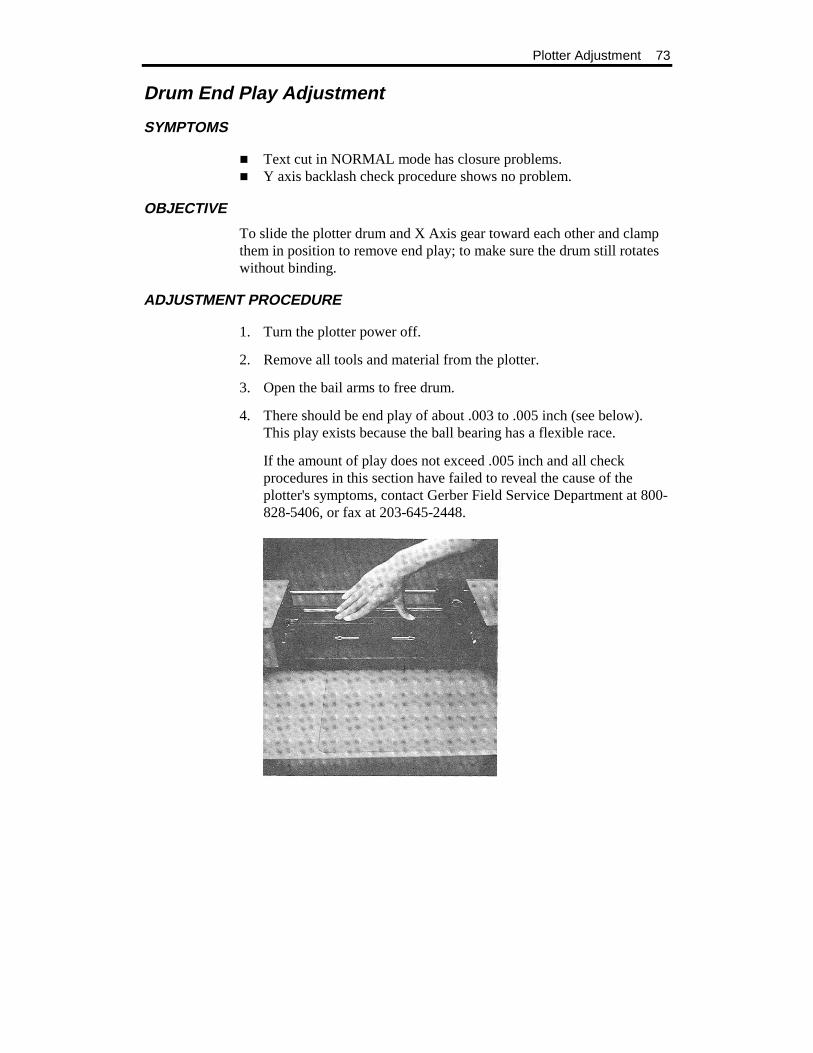
4. There should be end play of about .003 to .005 inch (see below). This play exists because the ball bearing has a flexible race.
If the amount of play does not exceed .005 inch and all check procedures in this section have failed to reveal the cause of the plotter's symptoms, contact Gerber Field Service Department at 800-828-5406, or fax at 203-645-2448.
74 GS15 plus
5. If there is more than .003 to .005 inch of play, remove the front cover. Lay the GS15 plus on its left side and remove the (2) Phillips head screws on the bottom edge closest to the front of the plotter. Then stand the plotter upright.
CAUTION: Do not rest the plotter on its right side. Do not use the way shaft to lift or turn the plotter.
6. Pull the front cover upwards and, at the same time, pull one side away from the plotter frame. Be careful not to lift the cover so high that the front panel cable disconnects. Pivot the cover to the side of the plotter.
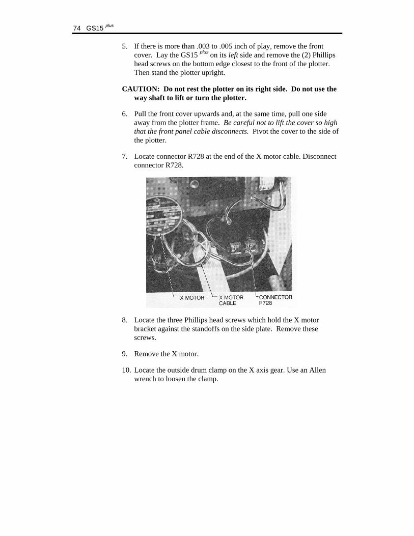
7. Locate connector R728 at the end of the X motor cable. Disconnect connector R728.
8. Locate the three Phillips head screws which hold the X motor bracket against the standoffs on the side plate. Remove these screws.
9. Remove the X motor.
10. Locate the outside drum clamp on the X axis gear. Use an Allen wrench to loosen the clamp.

Plotter Adjustment 75
11. Locate the centerline of the frame. Slide the plotter drum and the X axis gear toward the centerline of the frame and each other. Tighten the X axis drum clamp.
12. Slowly rotate the X axis gear two revolutions. Then rotate the X axis gear a quarter turn in the opposite direction.
13. Gently try to push the drum from end to end. If the adjustment is correct, the play will be between .003 and .005 inch.
14. Spin the drum. If the adjustment is correct, the drum will spin without binding.
15. If the tests in either step 13 or 14 fail, repeat steps 10 through 13 until the drum spins without binding and there is no end play.
Note: You may need to repeat this procedure several times to obtain correct adjustment.
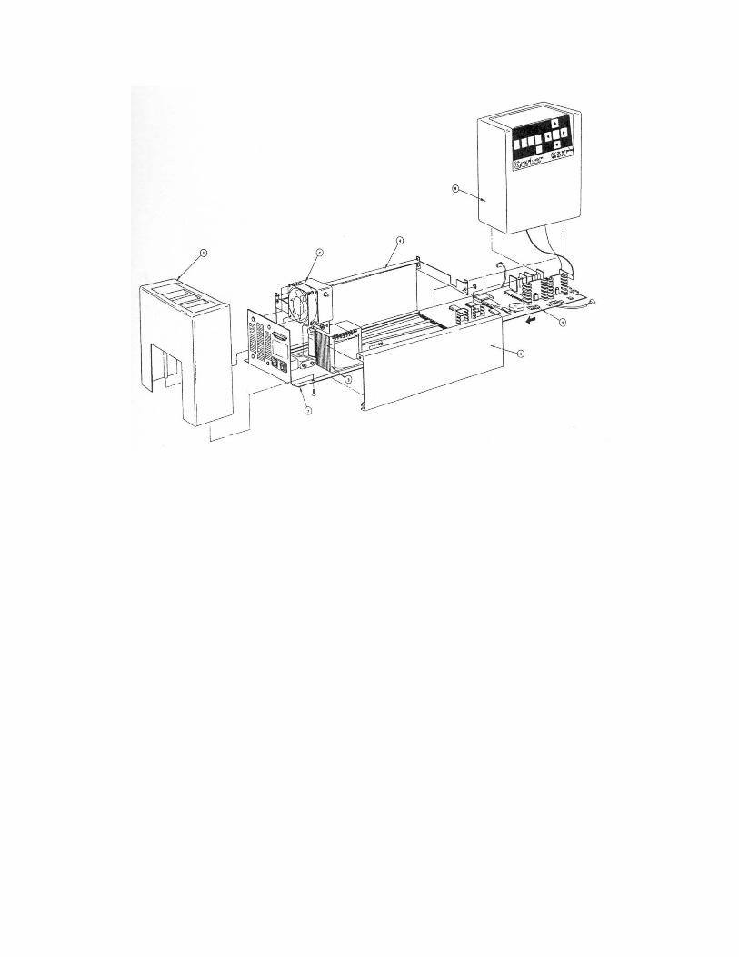
76 GS15 plus
16. After the adjustment is correct, reinstall the X motor. To do so, place the X motor on its standoff. Make sure the cable extends upward toward the ceiling.
17. Loosely install the three screws removed in step 8. Each must have a #8 lock washer and #8 flat washer. The lock washer must be closest to the screw head.
18. While applying pressure, tighten the three screws.
19. Turn on power to the plotter.
20. Load vinyl in the plotter, install the knife holder and cut a test plot. If closure problems persist, repeat the Adjustment Procedure from step 1.
21. If no closure problem appears, select AXIS SWAP mode. Cut a test plot. If closure problems persist, repeat the X Axis Backlash Adjustment Procedure.
22. If no closure problem appears, reinstall the front cover.


)


Plotter Adjustment 81
GS15 plus PLOTTER USER REFERENCE CARD
KEY/FUNCTION DESCRIPTION
RUN SINGLE Key
Plot Press RUN SINGLE to plot single jobs. The GS15 plus returns to the off-line status (as at power-up) after each job and waits for the operator to press RUN SINGLE key again to plot the next job.
Controlled Stop Press either RUN key to stop plotting at the next logical break in the program and check current job. Do not use slew keys or the orientation for the current job will be lost.
RUN CONT Key
Plot Press RUN CONT to plot two or more jobs continuously. The GS15 plus plots one job after the other without pausing between them and remains on-line until either RUN key is pressed.
Controlled Stop Press either RUN key to stop plotting at the next logical break in the program and check current job. Do not use slew keys or the orientation for current job will be lost.
Slew Keys (Arrow Keys) The arrow and SLOW keys do not function while a job is plotting, during an error condition, or while a RUN light is on, even if the plotter is idle.
Press arrow keys to position carriage and material between jobs:
! Up and down arrow keys move the carriage spindle between the rear and the front of the plotter.
! Left and right arrow keys rotate the drum and feed material through the plotter or back toward the roll holder.
Slow Key Hold the SLOW key while simultaneously pressing any Arrow key. This slows carriage movement for exact positioning.
Reset Key
Emergency Stop Press RESET key to stop GS15 plus operation, clear the current job from the buffer, and return the plotter to off-line status.
Clear Press the RESET key to stop the error signal after a power-up or plotting failure. (See Error Conditions Section.)
Access Hold the RESET key at power-up to access additional diagnostics. (See Special Diagnostics Section.)
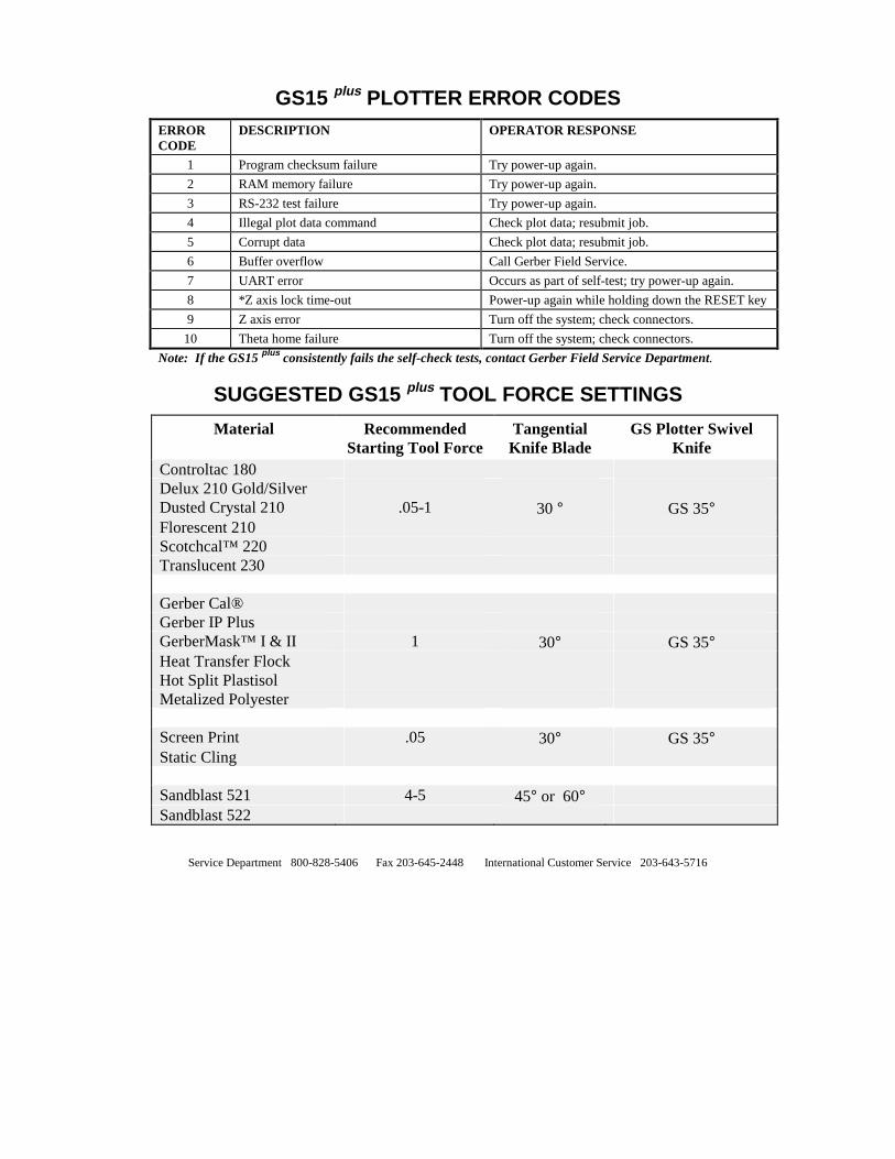
GS15 plus PLOTTER ERROR CODESERROR CODE
DESCRIPTION OPERATOR RESPONSE
1 Program checksum failure Try power-up again.
2 RAM memory failure Try power-up again.
3 RS-232 test failure Try power-up again.
4 Illegal plot data command Check plot data; resubmit job.
5 Corrupt data Check plot data; resubmit job.
6 Buffer overflow Call Gerber Field Service.
7 UART error Occurs as part of self-test; try power-up again.
8 *Z axis lock time-out Power-up again while holding down the RESET key
9 Z axis error Turn off the system; check connectors.
10 Theta home failure Turn off the system; check connectors.
Note: If the GS15 plus consistently fails the self-check tests, contact Gerber Field Service Department.
SUGGESTED GS15 plus TOOL FORCE SETTINGS
Material Recommended Starting Tool Force
Tangential Knife Blade
GS Plotter Swivel Knife
Controltac 180 Delux 210 Gold/Silver Dusted Crystal 210 .05-1 30 ° GS 35° Florescent 210 Scotchcal™ 220 Translucent 230 Gerber Cal® Gerber IP Plus GerberMask™ I & II 1 30° GS 35° Heat Transfer Flock Hot Split Plastisol Metalized Polyester Screen Print .05 30° GS 35° Static Cling Sandblast 521 4-5 45° or 60° Sandblast 522
Service Department 800-828-5406 Fax 203-645-2448 International Customer Service 203-643-5716

Plotter Adjustment 3
INDEX
Add Plotter ...................................12 Adjustment
drum end play ...........................73 theta axis (tool rotation) ...........61 X axis backlash.........................66 Y axis backlash.........................69 Z axis (tool height) ...................56
Arrow keys ...................................35 Axis belt adjustment.....................66 Axis blacklash adjustment............69 Bail arms.......................................52 Blade.......................................27, 30
damage......................................27 replacement...............................30 replacement .............................31 wear ..........................................27
Cap, tool .......................................21 Carriage spindle
bore .....................................49, 61 Cleaning, routine ..........................50 Closure problems........61, 66, 69, 73 Communication parameters............8 Conventions....................................4 Cover, plotter
front removal ................66, 69, 74 rear removal..............................58
Customer Support ...........................2 Cut test, X08.................................45 Delete plotter ................................12 Diagnostic options........................42 Diagnostics .............................40, 41 Drum end play adjustment............73 Drum, rubber ................................15 Error
codes .........................................48 signal...................................33, 47
Front panel....................................34 Fuse replacement ..........................53
INIT KNIFE key...........................36 Initial setting at power-up ......10, 33 Installation
pen holder.................................22 plotter .........................................7 pounce wheel holder ................25
Jagged edges, character ................61 Key, front panel............................34
Arrow keys ...............................35 INIT ..........................................36 RESET......................................40 RUN CONT........................38, 43 RUN SINGLE ..............37, 38, 43 SLEW (Also see Arrow keys) ...35 SLOW.......................................42 SLOW.......................................35 SWIVEL...................................36
Keyway.........................................22 Knife blades
changing ...................................30 Knife blades, changing.................29 Knife holder .................................56 Lift washer, tool ...........................22 Light (s), front panel ....................38 Lubrication, routine................50, 51 Material
inconsistent tool contact with...57 loading......................................15 tool force settings .....................19
Package Contents ...........................5 Pen
height gage ...............................23 replacement ........................23, 24
Pen holder...............................22, 23 Pen Holder
installation................................22 Perforate (See Pounce).................25 Plot

continuous exercise ..................39 single exercise ..........................38 Square/Circle test plot42, 44, 45, 60 Wagon Wheel test plot .......43, 60
Plotter ...........................................56 adding plotter............................12 assign default plotter ................13 delete plotter .............................12 installation ..................................7 speed ...................................25, 26
Plotter adjustment.57, 61, 66, 69, 73 Pounce wheel................................25
holes, aligned............................25 holes, off-center........................25 replacement...............................26
Pounce wheel holder ....................25 Pounce Wheel Holder
installation ................................25 Power cord................................9, 53 Power-up.......................................10
RESET key held at ...................40 RESET key ...................................40 Roll holder, material.....................15 RS-232 loop-back .........................42 RUN CONT key ...........................38 RUN SINGLE key........................37 Slew keys................................35, 39 SLOW key ....................................35 Sprockets ................................16, 52 Square/Circle test plot ......42, 44, 60 Stop, controlled ......................37, 39 Stop, emergency ...........................40 Swivel knife..................1, 28, 31, 36 Tangential knife..................1, 28, 36 Theta axis
adjustment ................................61 Tone..............................................33 Tool force
adjustment ..........................19, 20 dial ............................................19 housing .....................................62 pouncing ...................................26
settings......................................29 Tool height adjustment.................57 Tool rack, molded ..................21, 25 Tool rotation adjustment ..............61 Troubleshooting ...........................56 Vinyl.............................................15 Wagon Wheel test plot ...........43, 60 X axis
backlash adjustment .................69 X, Y, theta axes
lock time-out ............................48 X, Y, Z axes
lock time-out ............................48 Y axis
backlash adjustment .................69 Z axis
tool height adjustment ..............56 tool height adjustment ..............57

151 Batson Drive Manchester, CT 06040
U SA
P57347A Rev B