Embed Size (px)
Citation preview

LIBRETTO ISTRUZIONI
INSTRUCTIONS BOOKLET
GEBRAUCHSANWEISUNG
MODE D'EMPLOI
MANUAL DE INSTRUCCIONES
ИНСТРУКЦИИ
INSTRUKCJA OBSŁUGI
MANUAL DE INSTRUÇÕES
BRUGSANIVSNINGER
INSTRUKTIONSBOK
OHJEKIRJA
BRUKSANVISNING
gruppo incasso
Használati útmutató

2 32
262
1029
150
105
3
294
93
101
7 7
80
263
259
319
FORA
TURA
PER
INCA
SSO
/ H
OLE
SIZ
ES: 1
029x
262
min 12/max 20
GRUPPO INCASSO 100
GRUPPO INCASSO 100: 15 KG
800m3/h

2 33
751
262 7
76
294
120
74
739
5
02
259
263
337
FORA
TURA
PER
INCA
SSO
/ H
OLE
SIZ
ES: 7
51x2
62
min 12/max 20
GRUPPO INCASSO 70
GRUPPO INCASSO 70: 12 KG
600m3/h
Nyílá
s mér
ete:
751x
262

4 54
751
262 7
76
294
93
150
739
5
02
319
259
263
FORA
TURA
PER
INCA
SSO
/ H
OLE
SIZ
ES: 7
51x2
62
min 12/max 20
GRUPPO INCASSO 70: 12 KG
800m3/h
GRUPPO INCASSO 70
Az oldalsó kivezető nyílás csak álmennyezettel használható
Nyílá
s mér
ete:
751x
262

4 55
506
262
494
2
57
120
531
294
74
337
min 12/max 20
259
263
FORA
TURA
PER
INCA
SSO
/ H
OLE
SIZ
ES: 5
06x2
62
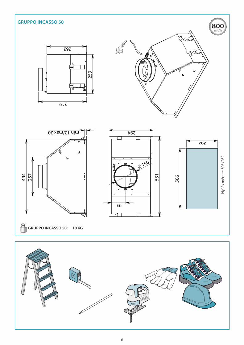
GRUPPO INCASSO 50: 10 KG
600m3/h
GRUPPO INCASSO 50
Nyílá
s mér
ete:
506x
262
6 76
506
262
494
2
57
531
294
150
93
259
263
319
FORA
TURA
PER
INCA
SSO
/ H
OLE
SIZ
ES: 5
06x2
62
min 12/max 20
GRUPPO INCASSO 50: 10 KG
800m3/h
GRUPPO INCASSO 50
Nyílá
s mér
ete:
506x
262

6 77
620
mm
(m
in)
4
2
MERM
ERM
3
5
6
1
1
MO
3
MO
Max 20 mmMin 12 mm
2
A
C
B
D

8 98
MO
V1 (x4)
Smontaggio!Disassembly!
1
V1 (x4)V1 (x4)
OK!
2 3
ø 15ø 12600
m3/h
150mm122mm
800m3/h
E
F G
szétszerelés

8 99
1
5
2 3 4
3
1 2
12V
1
2
3
600m3/h
800m3/h
H
I
M L
MAGNETE - MAGNET mágnes

10 11
Biztonsági figyelmeztetések és utasítások
Beüzemelésre vonatkozó figyelmeztetésekMűszAki kivitelezésre voNAtkozó figyelMeztetések
a telepítést képzett és a megfelelő gyakorlattal bíró telepítő személyzet végezheti el az útmutatóban foglalt utasítások és az érvényes előírások betartása mellett.
• az elszívó beüzemelése előtt ellenőrizzük az összetevő alkatrészek sértetlen állapotát. amennyiben sérülést, rendellenességet észlelünk, ne folytassuk a beüzemelési eljárást, ehelyett forduljunk a forgalmazóhoz.
• ne folytassuk a beüzemelést, ha az elszívón külső, esztétikai jellegű sérülést észlelünk. Helyezzük vissza a készüléket a gyá-ri csomagolásba, majd forduljunk a forgalmazóhoz. a beüzemelést követően esztétikai sérülés miatti bárminemű követelési igény érvényét veszti.
• A telepítés során mindig használjunk megfelelő védőfelszerelést (pl. munkavédelmi cipőt), ügyeljünk a tiszta környezetre, munka-végzésre.
• a rögzítő készlet elemei (tartozékként járnak az elszívóhoz), melyek a biztonsági lánc rögzítésére szolgálnak, téglafalhoz törté-nő rögzítésre szolgálnak. eltérő anyagú, szerkezetű fal esetén szerezzünk be megfelelő rögzítőelemeket, figyelembe véve a fal erősségét és az elszívó súlyát (utóbbit lásd az útmutató műszaki adatokat tartalmazó részében).
• Ne feledjük, hogy a tartozékként kapott rögzítőelemektől eltérő rögzítőelemekkel történő szerelés elektromos és szerkezeti szige-telési veszélyeket hordoz magában.
• Ne módosítsuk a berendezés elektromos, mechanikai és funkcionális rendszereit.• Ne telepítsük a készüléket szabadtérben, ne tegyük ki környezeti hatásoknak (esőnek, szélnek stb.).• Miután a rozsdamentes acél elszívó beüzemelésre került, azonnal távolítsuk a védőfólia után esetleges megmaradó maradékanya-
gokat, valamint zsír- és olajfoltokat, melyek ha nem kerülnek eltávolításra, visszafordíthatatlanul károsíthatják az elszívó felületét. ehhez a gyártó külön nedves törlőkendőt ajánl, amely külön megvásárolható.
elektroMos bekötésre voNAtkozó biztoNsági figyelMeztetések az elektromos rendszer, melyre az elszívó csatlakoztatásra kerül, meg kell feleljen az érvényes szabályoknak, előírások-nak, valamint a telepítési országban érvényes szabályozásnak megfelelő földeléssel kell rendelkezzen. emellett az eu-rópai uniós elektromágneses kompatibilitásra vonatkozó előírásoknak is meg kell feleljen.
• Az elszívó telepítését megelőzően ellenőrizzük, hogy a hálózati áram megfeleljen a készülék belsejében található típustábláján je-lölt paraméterekkel.
• A csatlakozó aljzat, melyhez a készüléket csatlakoztatjuk, elérhető közelségben legyen: amennyiben ez nem megoldható, megsza-kítón keresztül csatlakoztassuk a készüléket, melyet lekapcsolva a készülék azonnal áramtalanítható.
• Az elektromos hálózatban, az elszívó csatlakoztatása érdekében végrehajtott bárminemű módosítást kizárólag képzett szakember (villanyszerelő) hajthat végre.
• A készülék tulajdonságainak módosítása veszélyes. Amennyiben a készülék meghibásodna, ne kíséreljük meg magunk megjavítani, ehelyett forduljunk márkaszervizhez vagy a forgalmazóhoz.
• az elszívó beüzemelésekor húzzuk ki a dugvillát a csatlakozó aljzatból, vagy kapcsoljuk le a megszakítót.füstgáz kivezetésre voNAtkozó biztoNsági figyelMeztetések• A készüléket ne csatlakoztassuk égéstermék kivezetésére szolgáló (pl. bojlertől, kandallótól jövő) füstcsőhöz, kéményhez.• Mielőtt telepítjük az elszívót, ellenőrizzük, hogy a levegő szabadtérbe történő kivezetésére vonatkozó összes előírás betartásra ke-
rült.
felHasználóra vonatkozó figyelmeztetésekáltAláNos figyelMeztetések
ezen figyelmeztetések a felhasználó és más személyek személyes biztonságának megőrzésére szolgálnak. nagyon fon-tos, hogy mielőtt a telepítést megkezdjük, vagy tisztítást hajtunk végre, az útmutatót teljes terjedelmében gondosan olvassuk át.
• a gyártó elhárít mindennemű felelősséget, amely a jelen útmutatóban foglalt utasítások, illetve ezen belül is kiemelten a be-üzemelésre, használatra, karbantartásra vonatkozó biztonsági figyelmeztetések figyelmen kívül hagyásából eredően, közvet-lenül vagy közvetett módon emberben, állatban dologi tárgyban esett kárra vonatkozik.
• fontos, hogy az útmutatót a készülékkel együtt őrizzük meg egy esetleges későbbi tájékozódás céljából. amennyiben a ké-szülék eladásra, átadásra kerül, gondoskodjunk róla, hogy az útmutató is átadásra kerüljön az új tulajdonos számára, hogy ő is megismerhesse a vonatkozó veszélyeket és a használat módját.
• a telepítést kizárólag képzett szakember végezheti, betartva a vonatkozó előírásokat és az útmutatóban foglalt utasításokat.• ne használjuk az elszívót úgy, hogy a tápkábel sérült vagy egyéb alkatrész hibás, károsodott. áramtalanítsuk a készüléket, majd
forduljunk a forgalmazóhoz, márkaszervizhez. kizárólag eredeti gyári alkatrészeket használjunk. Ne kíséreljük magunk megjavítani a készüléket. A képzetlen személy által végrehajtott beavatkozások kárt tehetnek a készülékben (melyre a gyártói jótállás nem vo-natkozik), illetve személyi sérülés következhet be.
• Ne módosítsuk a készülék elektromos, mechanikus, funkcionális rendszereit. Az elektromos hálózatban, az elszívó csatlakoztatása érdekében végrehajtott bárminemű módosítást kizárólag képzett szakember (villanyszerelő) hajthat végre.
reNdeltetésszerű hAszNálAt• A készülék kizárólag a főzés során keletkező szagok, pára elszívására szolgál nem professzionális háztartási jellegű konyhákban: bár-
milyen ettől eltérő használati mód helytelennek minősül, és emberi személy, háziállat sérüléséhez, anyagi kárhoz vezethet.• A készüléket kizárólag 8 év feletti személyek használhatják, illetve csökkentett szellemi, fizikai, érzékszervi képességekkel bíró sze-
mélyek mindaddig, amíg a használat egy, az ő biztonságukért felelős személy felügyelete mellett történik vagy a készülék biz-tonságos használatára és a kapcsolódó veszélyekre vonatkozóan megfelelő utasításokat kaptak. felügyelet nélkül gyermek tisztítási vagy karbantartási műveletet nem végezhet.

10 11
tisztításrA, hAszNálAtrA voNAtkozó figyelMeztetések• tisztítást, karbantartási műveletet megelőzően áramtalanítsuk a készüléket a dugvilla fali aljzatból történő kihúzásával vagy a
megszakító lekapcsolásával.• Ne használjuk az elszívót nedves kézzel vagy mezítláb.• Mindig ellenőrizzük, hogy amikor a készülék ki van kapcsolva, az összes elektromos elem (ventilátor, lámpák) ki legyenek kapcsolva.• Az elszívóra helyezett vagy akasztott (amennyiben ez lehetséges) tárgy tömege nem haladhatja meg a 1,5 kg-ot.• bő zsírban, olajban történő sütésnél körültekintően járjunk el: a felforrósított olaj könnyen lángra lobban.• Nyílt lánggal ne főzzünk az elszívó alatt.• Az elszívó alatt ne flambírozzunk.• A fém zsírszűrők nélkül ne használjuk az elszívót: zsír és kosz gyűlik fel enélkül a készülékben, amely meghibásodáshoz vezethet.• A tűzhely használata során az elszívó külső elemei is átforrósodhatnak. • tisztítási műveletet ne hajtsunk úgy végre, hogy az elszívó egyes elemei még forrók.• A tisztítást kizárólag az útmutatóban foglaltaknak megfelelőn hajtsuk végre, eltérő esetben tűzveszély áll fenn.• Amikor a készülék tartósan használaton kívül lesz, a megszakítót kapcsoljuk le.
Amennyiben az elszívóval egyidejűleg gázzal vagy egyéb üzemanyaggal működő készüléket (pl. bojlert, kandallót, kályhát stb. használunk), ügyeljünk, hogy a helyiség, melynek levegője elszívásra kerül, megfelelően szellőzzön (a vonatkozó előírá-sok betartásával).
Meghibásodás esetére voNAtkozó figyelMeztetések• ne használjuk a készüléket úgy, hogy a tápkábel vagy egyéb alkatrész károsodott. áramtalanítsuk a készüléket, majd forduljunk
a forgalmazóhoz, márkaszervizhez. kizárólag eredeti gyári alkatrészeket használjunk. ne kíséreljük magunk megjavítani a készülé-ket. a képzetlen személy által végrehajtott beavatkozások kárt tehetnek a készülékben (melyre a gyártói jótállás nem vonatko-zik), illetve személyi sérülés következhet be.
A gyártó fenntartja a jogot, hogy külön értesítés nélkül módosításokat eszközöljön a készüléken. Jelen útmutató mind részleges, mind teljes körű nyomtatása, fordítása, többszörösítése a gyártó külön engedélyével történhet.Az útmutatóban szereplő műszaki adatok, grafikus ábrák kizárólag tájékoztató jellegűek. Az útmutató eredetileg olasz nyelven ké-szült. A gyártó átírási, fordítási hibákért felelősséget nem vállal.
Beüzemelés (kizárólag szakképzett személynek szól)
a telepítést megelőzően gondosan olvassuk át az előző oldalon szereplő biztonsági utasításokat.
műszaki adatokA műszaki adatok a készülék belsejében található típustáblán olvashatók.
elHelyezésa főzésre szolgáló berendezés legmagasabb pontja, illetve az elszívó legalsó pontja közötti minimális távolság a 7. oldalon, az ábrán került feltüntetésre.általánosságban gáztűzhely legmagasabb pontja és az elszívó legalacsonyabb pontja közötti ajánlott távolság 65 cm. Azonban a 2002.07.11-én született tC61-es eN60335-2-31szabvány (7.12.1. pont szerint, 15-ös értekezlet 10.11. elem) értelmezése szerint a je-lölt mértékig a távolság lecsökkenthető.Amennyiben a gáztűzhely gyártói útmutatója nagyobb távolságot ír elő, akkor az az irányadó.Ne telepítsük a készüléket szabadtérbe, ne tegyük ki környezeti hatásoknak (eső, szél stb.).
elektromos csatlakoztatás (kizárólag szakképzett személynek szól) mielőtt bármilyen műveletet végrehajtanánk a készüléken, áramtalanítsuk azt, csatlakoztassuk le a hálózati áramkör-ről. ellenőrizzük, hogy a készülék belsejében a vezetékek nem lazultak-e ki, nem szakadtak-e el, ilyen esetben mindig forduljunk a legközelebbi márkaszervizhez. az elektromos bekötéseket kizárólag képzett szakember végezheti. a csat-lakoztatás kizárólag az érvényes előírások betartása mellett történhet
A hálózati áramkörhöz történő csatlakoztatást megelőzően ellenőrizzük az alábbiakat:• a tápfeszültség megfelel-e a készülék belsejében található típustáblán jelölt paraméterekkel,• ellenőrizzük, hogy az elektromos hálózat elbírja a készülék okozta terhelést (a műszaki paramétereket a készülék belsejében lévő tí-
pustáblán találjuk).,• csatlakoztatás követően a tápkábel és a dugvilla ne érjen 70°C-nál magasabb hőmérsékletű alkatrészhez,• a hálózati áramkör megfelelően csatlakozik a földelővezetékhez a hatályos előírások szerint,• azon csatlakozó aljzat, melyhez a készüléket csatlakoztatni kívánjuk, elérhető közelségben legyen.egyes készülékeknél a tápkábelhez nem jár dugasz, itt mindig „szabványos” dugaszt kell alkalmaznunk a következő szempontok fi-gyelembevétele mellett: a sárga és zöld színű vezeték mindig a földelővezeték, a kék vagy fehér színű vezeték a nulla vezeték, a bar-na vezeték a fázis. A tápkábelre eső terhelésnek megfelelő dugvillát alkalmazzunk, melyet az ehhez való hálózati aljzathoz csatlakoz-tassunk. Amennyiben a készülékhez nem jár tápkábel és dugvilla, a hálózati áramkörről történő leválasztáshoz olyan megszakító be-rendezést alkalmazzunk, ahol az érintkezők között rés iii-as kategóriájú túlfeszültség esetén is teljes leválasztást biztosítanak, illetve ezen megszakító berendezést az érvényes előírásoknak megfelelően kell a hálózati áramkörbe beiktatni.A sárga/zöld földelővezetéket a megszakító nem bonthatja.A gyártó elhárít minden felelősséget, amely a biztonsági előírások be nem tartásából ered.

12 13
pára kivezetés (kizárólag szakképzett személynek szól)külső kivezetéses változAt (elszívás)ezen változat esetén a konyhai gőzök és pára egy csövön keresztül a szabadtérbe kerül kivezetésre.A készülék tetején található motor levegő kivezető nyílásához egy csövet kell csatlakoztatni, amely egy külső nyílás felé vezeti a gőzöket, párát.tartsuk be a levegő külső, szabadtérbe történő kivezetésére szolgáló előírásokat, illetve ne csatla-koztassuk a készüléket égéstermék (bojleré, kandallóé stb.) elvezetésére szolgáló kéményhez, lég-csatornához.A pára kivezetésére szolgáló cső:- átmérője ne legyen kisebb a készülék csatlakozó szerelvényének átmérőjénél,- a vízszintes szakaszokon enyhén lejtsen lefelé, így a kicsapódó nedvesség nem folyhat vissza a készü-
lék felé,- a lehető legkevesebb ívet, könyököt alkalmazzuk,- a lehető legrövidebb legyen (a számos ívvel rendelkező, hosszú csövek az elszívási teljesítményt ront-
hatják és a visszacsapószelep beremeghet)Amennyiben a kivezető cső hideg légtéren át fut (pl. padlástéren át), előfordulhat, hogy víz csapódik ki a
hirtelen hőmérséklet változások okán. ez esetben a csövet szigetelnünk kell.A 800 m/ó-s teljesítményű motorral ellátott készülék egy visszacsapószeleppel van ellátva, melynek feladata, hogy megakadályozza a külső levegő beáramlását, amikor a készülék nem működik: részletesen lásd a 7. oldalon a
20
FUMES DISCHARGE (only intended for personnel qualified to assemble the hood)
EXTERNAL EXHAUST HOOD VERSION (SUCTION)In this version, the kitchen fumes and vapours are conveyed outside through an exhaust pipe.The air outlet fitting that extends from the upper part of the hood must be connected with the pipe that conducts the fumes and vapours to an external output.Do not connect the equipment to discharge pipes of fumes produced from combustion (for example boil-ers, fireplaces, etc) and you are to comply with the regulations in force regarding external air discharge.The fumes outlet pipe must have:- a diameter not less than that of the hood fitting;- a slight slope downwards (drop) in the horizontal sections to prevent any formation of condensation from flowing back to the hood;- the minimum required number of bends;- minimum required length (long pipes with various bends can reduce suction performance of the hood and trigger vibrations of the check valve).If the fumes outlet pipe passes through cold environments such as attics, etc., it is possible that water condensation forms due to sudden changes in temperature. In this case, you are required to insulate the pipes.
The hood supplied with an 800 m3/h motor is equipped with a check valve whose function is to prevent external air exchange when the hood is not
operating: refer to the instructions C on page 7 for assembly.When the kitchen hood is used simultaneously with other appliances that use gas or other fuels, the room must have sufficient ventila-tion, in accordance with regulations in force.
The active carbon filters in this version are to be removed. Refer to the instructions L on page 9 for removal.
Deviation for Germany: when the kitchen hood is used at the same time as appliances that are powered by energy other than electricity, the negative pressure in the room must not exceed 4 Pa (4 x 10⁻⁵ bar).
HOOD VERSION WITH INTERNAL RECIRCULATION (FILTERING)In this model, air passes through the active carbon filters to be purified and is then recycled into the kitchen environ-ment.
Check that the active carbon filters are assembled onto the hood, if not, install them as indicated in the in-
structions L on page 9.
If the hood is set up with a filtering version, the check valve must not be assembled: remove it if it is on the air outlet
fitting of the motor (carry out operations described in the instructions C on page 7 in reverse order).
If you wish to install the filtering version hood, drill a hole in the wall structure where it will be moun-ted, of a suitable size to allow purified air to exit the structure. This hole should be connected to the hood's air outlet fitting with a suitable pipe to protect the inside of the structure from humidity and
residues of fat particles.
ASSEMBLY INSTRUCTIONS (only intended for personnel qualified to assemble the hood)
Before installing the hood, make sure the structure in which it will be fixed can safely support the device: the weight of the hood, in various configurations, is reported in the technical sheets at the beginning of this booklet.
Phase B page 7 • Drill the hole intended for recessing (for the size of the hole, see the technical sheets at the beginning of this booklet).
Phase C page 7• Only for the external exhaust (suction) version with an 800m3/h motor: if you wish, install the check valve (M); if the fitting
(ERM) is installed, remove it (Fig. 1 ), install the check valve (M) as illustrated in the figures (Fig. 2 - 3 - 4 - 5 ) and put the previously removed fitting (ERM) back in (Fig. 6 ).
Phase D page 7• Insert the hood at the bottom of the wall unit (Fig. 1 ): the springs (MO) open and temporarily support the hood on the structure (Fig. 2
- 3 ).
Phase E page 8
• Open the perimeter suction panel (see instructions H page 9), tighten the 4 screws (V1) to open the springs (MO) (Fig. 2 ) and block the hood at the bottom of the wall unit (Fig. 3 )..
Make sure that the springs (MO) grip the bottom of the wall unit.Avoid using force to block the hood: use the provided tool as indicated.
• Make sure that the hood is well secured to the structure and close the perimeter suction panel.
EXTERNAL EXHAUST HOOD VERSION (SUCTION)
• Connect the hood’s air outlet fitting to the external exhaust with a suitable pipe (Phase F page 8).
HOOD VERSION WITH INTERNAL RECIRCULATION (FILTERING)
• Check that the active carbon filters are assembled onto the hood; if not, install them as instructed L page 9.• If installed, remove the fitting (ERM) and any check valve (M) installed on the hood’s air outlet fitting (perform, in reverse order, the oper-
ation described in the instructions C page 7).
ábrán.a szabványoknak megfelelően amennyiben a helyiségben egyidejűleg más, gázt vagy egyéb üzemanyagot égető berendezések működnek, biztosítani kell a megfelelő szellőzést.
Az aktív szénszűrőt a fenti esetben ki kell szerelni. lásd a 9. oldalon az
20
FUMES DISCHARGE (only intended for personnel qualified to assemble the hood)
EXTERNAL EXHAUST HOOD VERSION (SUCTION)In this version, the kitchen fumes and vapours are conveyed outside through an exhaust pipe.The air outlet fitting that extends from the upper part of the hood must be connected with the pipe that conducts the fumes and vapours to an external output.Do not connect the equipment to discharge pipes of fumes produced from combustion (for example boil-ers, fireplaces, etc) and you are to comply with the regulations in force regarding external air discharge.The fumes outlet pipe must have:- a diameter not less than that of the hood fitting;- a slight slope downwards (drop) in the horizontal sections to prevent any formation of condensation from flowing back to the hood;- the minimum required number of bends;- minimum required length (long pipes with various bends can reduce suction performance of the hood and trigger vibrations of the check valve).If the fumes outlet pipe passes through cold environments such as attics, etc., it is possible that water condensation forms due to sudden changes in temperature. In this case, you are required to insulate the pipes.
The hood supplied with an 800 m3/h motor is equipped with a check valve whose function is to prevent external air exchange when the hood is not
operating: refer to the instructions C on page 7 for assembly.When the kitchen hood is used simultaneously with other appliances that use gas or other fuels, the room must have sufficient ventila-tion, in accordance with regulations in force.
The active carbon filters in this version are to be removed. Refer to the instructions L on page 9 for removal.
Deviation for Germany: when the kitchen hood is used at the same time as appliances that are powered by energy other than electricity, the negative pressure in the room must not exceed 4 Pa (4 x 10⁻⁵ bar).
HOOD VERSION WITH INTERNAL RECIRCULATION (FILTERING)In this model, air passes through the active carbon filters to be purified and is then recycled into the kitchen environ-ment.
Check that the active carbon filters are assembled onto the hood, if not, install them as indicated in the in-
structions L on page 9.
If the hood is set up with a filtering version, the check valve must not be assembled: remove it if it is on the air outlet
fitting of the motor (carry out operations described in the instructions C on page 7 in reverse order).
If you wish to install the filtering version hood, drill a hole in the wall structure where it will be moun-ted, of a suitable size to allow purified air to exit the structure. This hole should be connected to the hood's air outlet fitting with a suitable pipe to protect the inside of the structure from humidity and
residues of fat particles.
ASSEMBLY INSTRUCTIONS (only intended for personnel qualified to assemble the hood)
Before installing the hood, make sure the structure in which it will be fixed can safely support the device: the weight of the hood, in various configurations, is reported in the technical sheets at the beginning of this booklet.
Phase B page 7 • Drill the hole intended for recessing (for the size of the hole, see the technical sheets at the beginning of this booklet).
Phase C page 7• Only for the external exhaust (suction) version with an 800m3/h motor: if you wish, install the check valve (M); if the fitting
(ERM) is installed, remove it (Fig. 1 ), install the check valve (M) as illustrated in the figures (Fig. 2 - 3 - 4 - 5 ) and put the previously removed fitting (ERM) back in (Fig. 6 ).
Phase D page 7• Insert the hood at the bottom of the wall unit (Fig. 1 ): the springs (MO) open and temporarily support the hood on the structure (Fig. 2
- 3 ).
Phase E page 8
• Open the perimeter suction panel (see instructions H page 9), tighten the 4 screws (V1) to open the springs (MO) (Fig. 2 ) and block the hood at the bottom of the wall unit (Fig. 3 )..
Make sure that the springs (MO) grip the bottom of the wall unit.Avoid using force to block the hood: use the provided tool as indicated.
• Make sure that the hood is well secured to the structure and close the perimeter suction panel.
EXTERNAL EXHAUST HOOD VERSION (SUCTION)
• Connect the hood’s air outlet fitting to the external exhaust with a suitable pipe (Phase F page 8).
HOOD VERSION WITH INTERNAL RECIRCULATION (FILTERING)
• Check that the active carbon filters are assembled onto the hood; if not, install them as instructed L page 9.• If installed, remove the fitting (ERM) and any check valve (M) installed on the hood’s air outlet fitting (perform, in reverse order, the oper-
ation described in the instructions C page 7).
ábrán.Németországra vonatkozó külön előírás: amennyiben a páraelszívóval egyidejűleg más, nem elektromos árammal működő berende-zés is üzemel, a helyiségben a negatív nyomás nem haladhatja meg a 4 Pa-t (4x10e-5 bar).belső keriNgtetéses változAt (szűrés)
ebben a változatnál a levegő áthalad az aktív szénszűrőkön, majd visszaforgatásra kerül a konyha helyiségbe. ellenőrizzük, hogy az aktív szénszűrők be legyenek szerelve az elszívóba, ellenkező esetben a 9. oldalon szereplő
20
FUMES DISCHARGE (only intended for personnel qualified to assemble the hood)
EXTERNAL EXHAUST HOOD VERSION (SUCTION)In this version, the kitchen fumes and vapours are conveyed outside through an exhaust pipe.The air outlet fitting that extends from the upper part of the hood must be connected with the pipe that conducts the fumes and vapours to an external output.Do not connect the equipment to discharge pipes of fumes produced from combustion (for example boil-ers, fireplaces, etc) and you are to comply with the regulations in force regarding external air discharge.The fumes outlet pipe must have:- a diameter not less than that of the hood fitting;- a slight slope downwards (drop) in the horizontal sections to prevent any formation of condensation from flowing back to the hood;- the minimum required number of bends;- minimum required length (long pipes with various bends can reduce suction performance of the hood and trigger vibrations of the check valve).If the fumes outlet pipe passes through cold environments such as attics, etc., it is possible that water condensation forms due to sudden changes in temperature. In this case, you are required to insulate the pipes.
The hood supplied with an 800 m3/h motor is equipped with a check valve whose function is to prevent external air exchange when the hood is not
operating: refer to the instructions C on page 7 for assembly.When the kitchen hood is used simultaneously with other appliances that use gas or other fuels, the room must have sufficient ventila-tion, in accordance with regulations in force.
The active carbon filters in this version are to be removed. Refer to the instructions L on page 9 for removal.
Deviation for Germany: when the kitchen hood is used at the same time as appliances that are powered by energy other than electricity, the negative pressure in the room must not exceed 4 Pa (4 x 10⁻⁵ bar).
HOOD VERSION WITH INTERNAL RECIRCULATION (FILTERING)In this model, air passes through the active carbon filters to be purified and is then recycled into the kitchen environ-ment.
Check that the active carbon filters are assembled onto the hood, if not, install them as indicated in the in-
structions L on page 9.
If the hood is set up with a filtering version, the check valve must not be assembled: remove it if it is on the air outlet
fitting of the motor (carry out operations described in the instructions C on page 7 in reverse order).
If you wish to install the filtering version hood, drill a hole in the wall structure where it will be moun-ted, of a suitable size to allow purified air to exit the structure. This hole should be connected to the hood's air outlet fitting with a suitable pipe to protect the inside of the structure from humidity and
residues of fat particles.
ASSEMBLY INSTRUCTIONS (only intended for personnel qualified to assemble the hood)
Before installing the hood, make sure the structure in which it will be fixed can safely support the device: the weight of the hood, in various configurations, is reported in the technical sheets at the beginning of this booklet.
Phase B page 7 • Drill the hole intended for recessing (for the size of the hole, see the technical sheets at the beginning of this booklet).
Phase C page 7• Only for the external exhaust (suction) version with an 800m3/h motor: if you wish, install the check valve (M); if the fitting
(ERM) is installed, remove it (Fig. 1 ), install the check valve (M) as illustrated in the figures (Fig. 2 - 3 - 4 - 5 ) and put the previously removed fitting (ERM) back in (Fig. 6 ).
Phase D page 7• Insert the hood at the bottom of the wall unit (Fig. 1 ): the springs (MO) open and temporarily support the hood on the structure (Fig. 2
- 3 ).
Phase E page 8
• Open the perimeter suction panel (see instructions H page 9), tighten the 4 screws (V1) to open the springs (MO) (Fig. 2 ) and block the hood at the bottom of the wall unit (Fig. 3 )..
Make sure that the springs (MO) grip the bottom of the wall unit.Avoid using force to block the hood: use the provided tool as indicated.
• Make sure that the hood is well secured to the structure and close the perimeter suction panel.
EXTERNAL EXHAUST HOOD VERSION (SUCTION)
• Connect the hood’s air outlet fitting to the external exhaust with a suitable pipe (Phase F page 8).
HOOD VERSION WITH INTERNAL RECIRCULATION (FILTERING)
• Check that the active carbon filters are assembled onto the hood; if not, install them as instructed L page 9.• If installed, remove the fitting (ERM) and any check valve (M) installed on the hood’s air outlet fitting (perform, in reverse order, the oper-
ation described in the instructions C page 7).
ábra alapján szereljük be ezeket.Amennyiben az elszívót belső keringtetéses (szűrős) kivitelben telepítjük, a visszacsapószelepre (huzatgátló) nincs szükség: amennyiben a motor kivezető nyílására felszerelésre került, szereljük ezt le (fordított sorrend-ben hajtsuk végre a 7. oldalon a
20
FUMES DISCHARGE (only intended for personnel qualified to assemble the hood)
EXTERNAL EXHAUST HOOD VERSION (SUCTION)In this version, the kitchen fumes and vapours are conveyed outside through an exhaust pipe.The air outlet fitting that extends from the upper part of the hood must be connected with the pipe that conducts the fumes and vapours to an external output.Do not connect the equipment to discharge pipes of fumes produced from combustion (for example boil-ers, fireplaces, etc) and you are to comply with the regulations in force regarding external air discharge.The fumes outlet pipe must have:- a diameter not less than that of the hood fitting;- a slight slope downwards (drop) in the horizontal sections to prevent any formation of condensation from flowing back to the hood;- the minimum required number of bends;- minimum required length (long pipes with various bends can reduce suction performance of the hood and trigger vibrations of the check valve).If the fumes outlet pipe passes through cold environments such as attics, etc., it is possible that water condensation forms due to sudden changes in temperature. In this case, you are required to insulate the pipes.
The hood supplied with an 800 m3/h motor is equipped with a check valve whose function is to prevent external air exchange when the hood is not
operating: refer to the instructions C on page 7 for assembly.When the kitchen hood is used simultaneously with other appliances that use gas or other fuels, the room must have sufficient ventila-tion, in accordance with regulations in force.
The active carbon filters in this version are to be removed. Refer to the instructions L on page 9 for removal.
Deviation for Germany: when the kitchen hood is used at the same time as appliances that are powered by energy other than electricity, the negative pressure in the room must not exceed 4 Pa (4 x 10⁻⁵ bar).
HOOD VERSION WITH INTERNAL RECIRCULATION (FILTERING)In this model, air passes through the active carbon filters to be purified and is then recycled into the kitchen environ-ment.
Check that the active carbon filters are assembled onto the hood, if not, install them as indicated in the in-
structions L on page 9.
If the hood is set up with a filtering version, the check valve must not be assembled: remove it if it is on the air outlet
fitting of the motor (carry out operations described in the instructions C on page 7 in reverse order).
If you wish to install the filtering version hood, drill a hole in the wall structure where it will be moun-ted, of a suitable size to allow purified air to exit the structure. This hole should be connected to the hood's air outlet fitting with a suitable pipe to protect the inside of the structure from humidity and
residues of fat particles.
ASSEMBLY INSTRUCTIONS (only intended for personnel qualified to assemble the hood)
Before installing the hood, make sure the structure in which it will be fixed can safely support the device: the weight of the hood, in various configurations, is reported in the technical sheets at the beginning of this booklet.
Phase B page 7 • Drill the hole intended for recessing (for the size of the hole, see the technical sheets at the beginning of this booklet).
Phase C page 7• Only for the external exhaust (suction) version with an 800m3/h motor: if you wish, install the check valve (M); if the fitting
(ERM) is installed, remove it (Fig. 1 ), install the check valve (M) as illustrated in the figures (Fig. 2 - 3 - 4 - 5 ) and put the previously removed fitting (ERM) back in (Fig. 6 ).
Phase D page 7• Insert the hood at the bottom of the wall unit (Fig. 1 ): the springs (MO) open and temporarily support the hood on the structure (Fig. 2
- 3 ).
Phase E page 8
• Open the perimeter suction panel (see instructions H page 9), tighten the 4 screws (V1) to open the springs (MO) (Fig. 2 ) and block the hood at the bottom of the wall unit (Fig. 3 )..
Make sure that the springs (MO) grip the bottom of the wall unit.Avoid using force to block the hood: use the provided tool as indicated.
• Make sure that the hood is well secured to the structure and close the perimeter suction panel.
EXTERNAL EXHAUST HOOD VERSION (SUCTION)
• Connect the hood’s air outlet fitting to the external exhaust with a suitable pipe (Phase F page 8).
HOOD VERSION WITH INTERNAL RECIRCULATION (FILTERING)
• Check that the active carbon filters are assembled onto the hood; if not, install them as instructed L page 9.• If installed, remove the fitting (ERM) and any check valve (M) installed on the hood’s air outlet fitting (perform, in reverse order, the oper-
ation described in the instructions C page 7).
ábrán szereplő utasításokat). amennyiben a készüléket belső keringtetéses (szűrős) módban telepítjük, azon részre, ahol a ké-szülék telepítésre kerül, fúrjunk egy lyukat a szekrényelembe. a lyuk elég nagy méretű legyen ah-hoz, hogy a megtisztított levegő ki tudjon lépni a szekrényből. a lyukat megfelelő légcsatornával kössük össze az elszívó levegő kimeneti nyílásával, ezzel megakadályozzuk, hogy a szekrény bel-sejében pára és maradék zsírszemek csapódjanak ki.
szerelési útmutató (kizárólag szakképzett személynek szól) a készülék telepítése előtt győződjünk meg arról, hogy a szekrényelem, amelybe a készüléket beszereljük, biztonság-gal meg tudja tartani a készüléket. az elszívó különféle változatainak megfelelő össztömegek az útmutató elején fel-tüntetésre kerültek.
7. oldal – lépés• készítsünk egy nyílást a felső szekrényelem alján (a méreteket illetően az útmutató első részében szereplő műszaki adatok között
tájékozódhatunk).7. oldal – lépés• kizárólag 800 m3/ó-s motorral ellátott, külső kivezetéses (elszívásos) változat esetén – igény esetén helyezzük be a
visszacsapószelepet (m). amennyiben a csőcsonk (erm) felszerelése megtörtént, szereljük azt le ( . ábra), helyezzük fel a visszacsapószelepet (m) ( - - -
22
Phase C1 page 6
Only for version with external exhaust (suction): if required by the selected height (H1), it is possible to install the hood using only the trellis (T1) and the flue (G). • Attach the extension supporting elements (SP) to the trellis (T1) using the 8 self-threading screws (V4) through the pre-drilled holes (Fig. 1 )• Mark 4 drilling points on the ceiling (also identified on page 3 and 4), drill (Fig. 2 ) Put in 4 x ø 8mm expansion bolts and secure the
extension supporting elements (SP) to the ceiling by the relative screws (V1) (Fig. 3 ). With false ceilings, the extension supporting elements (SP) must always be bolted to the false ceiling: said false ceiling must be reinforced or somehow fitted with a solution that can guarantee safely attaching the hood to it, taking into account the strength of the used materi-als and the weight of the hood (reported on page. 2).The fixing kit (screws and plugs) supplied with the hood can only be used on masonry walls: should it be necessary to install the hood onto walls in a different material, assess other fixing systems keeping the wall resistance and weight of the hood in mind (indicated on page 2).
EXTERNAL EXHAUST HOOD VERSION (SUCTION)
• Phase D page 6 - Only for the version with an 800m3/h motor: if you wish, install the check valve (M); if the connection is installed take it down (Fig. 1 ), install the check valve (M) as illustrated in the figures (Fig. 2 - 3 - 4 - 5 ) and put the previously removed connection back in (ERM) (Fig. 6 ).
• Find the best length for the flexible (recommended) or rigid pipe to discharge the fumes and connect it suitably to the connection (Phase E page 6).
HOOD VERSION WITH INTERNAL RECIRCULATION (FILTERING)
• Ensure that the active carbon filters are assembled onto the hood, if not, install them as indicated in the instructions P on page 10. • If installed, remove the connection (ERM) and any check valve (M) installed on the hood's air outlet fitting (perform, in reverse order, the opera-
tion described in the instructions D page 6).
INSTALLATION ON CEILING Phases F - G1 - H - I - LINSTALLATION ON CEILING WITH FALSE CEILING Phases F - G2 - H - I - LINSTALLATION ON CEILING WITHOUT EXTENSION (H) AND TRELLIS (T) Phases M - NPhase F page 7• Insert the extension (H) into the flue (G) and secure them together with masking tape.• With external exhaust (suction) versions, it is possible to insert extension (H) with the slots facing downwards so that they are not visible when
the installation height allows it.
Phase G1 page 7 (only for installations on ceiling WITHOUT false ceiling)• Raise the assembly (H+G) until it is touching the ceiling (Fig. 1 ). • Attach the assembly (H+G) to the trellis (T) with 4 screws (V3) without tightening them all the way (Fig. 2 ).
Phase G2 page 7 (only for installations on ceiling WITH false ceiling)Attach the extension supporting elements (SP) to the trellis (T) with 8 self-threading screws (V4) being sure to press it up against the false ceiling Fig. 1 ).• Raise the assembly (H+G) until it is touching the false ceiling (Fig. 2 ). • Attach the assembly (H+G) to the extension supporting elements (SP) with 4 screws (V3) without tightening them all the way (Fig. 3 ).
Phase H page 8• Raise the hood so that it is near the trellis that is already attached to the ceiling (Fig. 1 ).• Centre the 4 metric screws, (V5) that are pre-screwed onto the trellis, (T1) (Fig. 2A ) on the holes on the hood; shift the hood sideways and tighten
the 4 metric screws definitively (V5) (Fig. 2B ).
Phase I page 8• Remove the masking tape that was temporarily holding the flue (G) and extension (H) (Fig. 1 )• Take out the 4 screws (V3) that attach the extension (H) to the trellis (T) (Fig. 2A ) or, with false ceilings, to the extension supporting elements (SP)
(Fig. 2B ) and slide the extension (H) downwards (Fig. 3 ). Keep the removed (V3) screws.• By lowering the extension (H) it is possible to connect the pipe (F) to the external discharge pipe (with the suction version)(Fig. 4 ).• Set up the electric connection only once the electric power supply has been cut off.
Phase L page 8• When the electrical connection is set up, as well as the discharge connection, raise the extension (H) (Fig. 1 ) and re-attach it to the trellis (T) (Fig.
2A ) or, with false ceilings, to the extension supporting elements (SP) (Fig. 2B ) by the 4 screws (V3).• Attach the flue (G) to the hood by 2 self-threading screws (V6) (Fig. 3 ).
INSTALLATION ON CEILING WITHOUT EXTENSION (H) AND TRELLIS (T)
Phase M page 9• Attach the flue (G) to the hood by 2 self-threading screws (V6) (Fig. 1 ).
Phase N page 9• Raise the hood towards the trellis (Fig. 1 ).• Set up the connection with the external discharge pipe and the electrical connection, performing the latter after disconnecting the electrical
power supply.• Centre the 4 metric screws, (V5) that are pre-screwed onto the trellis, (T1) (Fig. 2A ) on the holes on the hood; shift the hood sideways and tighten
the 4 metric screws definitively (V5) (Fig. 2B ).
. ábra), majd helyezzük vissza az imént leszerelt csőcsonkot (erm) ( .ábra). 7. oldal – lépés• helyezzük a készüléket a konyhaszekrény aljába ( . ábra, a rugók (Mo) kinyílnak, és ideiglenesen a szekrényhez rögzítik a készü-
léket ( - . ábra).8. oldal –
20
FUMES DISCHARGE (only intended for personnel qualified to assemble the hood)
EXTERNAL EXHAUST HOOD VERSION (SUCTION)In this version, the kitchen fumes and vapours are conveyed outside through an exhaust pipe.The air outlet fitting that extends from the upper part of the hood must be connected with the pipe that conducts the fumes and vapours to an external output.Do not connect the equipment to discharge pipes of fumes produced from combustion (for example boil-ers, fireplaces, etc) and you are to comply with the regulations in force regarding external air discharge.The fumes outlet pipe must have:- a diameter not less than that of the hood fitting;- a slight slope downwards (drop) in the horizontal sections to prevent any formation of condensation from flowing back to the hood;- the minimum required number of bends;- minimum required length (long pipes with various bends can reduce suction performance of the hood and trigger vibrations of the check valve).If the fumes outlet pipe passes through cold environments such as attics, etc., it is possible that water condensation forms due to sudden changes in temperature. In this case, you are required to insulate the pipes.
The hood supplied with an 800 m3/h motor is equipped with a check valve whose function is to prevent external air exchange when the hood is not
operating: refer to the instructions C on page 7 for assembly.When the kitchen hood is used simultaneously with other appliances that use gas or other fuels, the room must have sufficient ventila-tion, in accordance with regulations in force.
The active carbon filters in this version are to be removed. Refer to the instructions L on page 9 for removal.
Deviation for Germany: when the kitchen hood is used at the same time as appliances that are powered by energy other than electricity, the negative pressure in the room must not exceed 4 Pa (4 x 10⁻⁵ bar).
HOOD VERSION WITH INTERNAL RECIRCULATION (FILTERING)In this model, air passes through the active carbon filters to be purified and is then recycled into the kitchen environ-ment.
Check that the active carbon filters are assembled onto the hood, if not, install them as indicated in the in-
structions L on page 9.
If the hood is set up with a filtering version, the check valve must not be assembled: remove it if it is on the air outlet
fitting of the motor (carry out operations described in the instructions C on page 7 in reverse order).
If you wish to install the filtering version hood, drill a hole in the wall structure where it will be moun-ted, of a suitable size to allow purified air to exit the structure. This hole should be connected to the hood's air outlet fitting with a suitable pipe to protect the inside of the structure from humidity and
residues of fat particles.
ASSEMBLY INSTRUCTIONS (only intended for personnel qualified to assemble the hood)
Before installing the hood, make sure the structure in which it will be fixed can safely support the device: the weight of the hood, in various configurations, is reported in the technical sheets at the beginning of this booklet.
Phase B page 7 • Drill the hole intended for recessing (for the size of the hole, see the technical sheets at the beginning of this booklet).
Phase C page 7• Only for the external exhaust (suction) version with an 800m3/h motor: if you wish, install the check valve (M); if the fitting
(ERM) is installed, remove it (Fig. 1 ), install the check valve (M) as illustrated in the figures (Fig. 2 - 3 - 4 - 5 ) and put the previously removed fitting (ERM) back in (Fig. 6 ).
Phase D page 7• Insert the hood at the bottom of the wall unit (Fig. 1 ): the springs (MO) open and temporarily support the hood on the structure (Fig. 2
- 3 ).
Phase E page 8
• Open the perimeter suction panel (see instructions H page 9), tighten the 4 screws (V1) to open the springs (MO) (Fig. 2 ) and block the hood at the bottom of the wall unit (Fig. 3 )..
Make sure that the springs (MO) grip the bottom of the wall unit.Avoid using force to block the hood: use the provided tool as indicated.
• Make sure that the hood is well secured to the structure and close the perimeter suction panel.
EXTERNAL EXHAUST HOOD VERSION (SUCTION)
• Connect the hood’s air outlet fitting to the external exhaust with a suitable pipe (Phase F page 8).
HOOD VERSION WITH INTERNAL RECIRCULATION (FILTERING)
• Check that the active carbon filters are assembled onto the hood; if not, install them as instructed L page 9.• If installed, remove the fitting (ERM) and any check valve (M) installed on the hood’s air outlet fitting (perform, in reverse order, the oper-
ation described in the instructions C page 7).
lépés• Nyissuk fel a külső elszívó panelt (lásd a 9. oldalon a
22
Phase C1 page 6
Only for version with external exhaust (suction): if required by the selected height (H1), it is possible to install the hood using only the trellis (T1) and the flue (G). • Attach the extension supporting elements (SP) to the trellis (T1) using the 8 self-threading screws (V4) through the pre-drilled holes (Fig. 1 )• Mark 4 drilling points on the ceiling (also identified on page 3 and 4), drill (Fig. 2 ) Put in 4 x ø 8mm expansion bolts and secure the
extension supporting elements (SP) to the ceiling by the relative screws (V1) (Fig. 3 ). With false ceilings, the extension supporting elements (SP) must always be bolted to the false ceiling: said false ceiling must be reinforced or somehow fitted with a solution that can guarantee safely attaching the hood to it, taking into account the strength of the used materi-als and the weight of the hood (reported on page. 2).The fixing kit (screws and plugs) supplied with the hood can only be used on masonry walls: should it be necessary to install the hood onto walls in a different material, assess other fixing systems keeping the wall resistance and weight of the hood in mind (indicated on page 2).
EXTERNAL EXHAUST HOOD VERSION (SUCTION)
• Phase D page 6 - Only for the version with an 800m3/h motor: if you wish, install the check valve (M); if the connection is installed take it down (Fig. 1 ), install the check valve (M) as illustrated in the figures (Fig. 2 - 3 - 4 - 5 ) and put the previously removed connection back in (ERM) (Fig. 6 ).
• Find the best length for the flexible (recommended) or rigid pipe to discharge the fumes and connect it suitably to the connection (Phase E page 6).
HOOD VERSION WITH INTERNAL RECIRCULATION (FILTERING)
• Ensure that the active carbon filters are assembled onto the hood, if not, install them as indicated in the instructions P on page 10. • If installed, remove the connection (ERM) and any check valve (M) installed on the hood's air outlet fitting (perform, in reverse order, the opera-
tion described in the instructions D page 6).
INSTALLATION ON CEILING Phases F - G1 - H - I - LINSTALLATION ON CEILING WITH FALSE CEILING Phases F - G2 - H - I - LINSTALLATION ON CEILING WITHOUT EXTENSION (H) AND TRELLIS (T) Phases M - NPhase F page 7• Insert the extension (H) into the flue (G) and secure them together with masking tape.• With external exhaust (suction) versions, it is possible to insert extension (H) with the slots facing downwards so that they are not visible when
the installation height allows it.
Phase G1 page 7 (only for installations on ceiling WITHOUT false ceiling)• Raise the assembly (H+G) until it is touching the ceiling (Fig. 1 ). • Attach the assembly (H+G) to the trellis (T) with 4 screws (V3) without tightening them all the way (Fig. 2 ).
Phase G2 page 7 (only for installations on ceiling WITH false ceiling)Attach the extension supporting elements (SP) to the trellis (T) with 8 self-threading screws (V4) being sure to press it up against the false ceiling Fig. 1 ).• Raise the assembly (H+G) until it is touching the false ceiling (Fig. 2 ). • Attach the assembly (H+G) to the extension supporting elements (SP) with 4 screws (V3) without tightening them all the way (Fig. 3 ).
Phase H page 8• Raise the hood so that it is near the trellis that is already attached to the ceiling (Fig. 1 ).• Centre the 4 metric screws, (V5) that are pre-screwed onto the trellis, (T1) (Fig. 2A ) on the holes on the hood; shift the hood sideways and tighten
the 4 metric screws definitively (V5) (Fig. 2B ).
Phase I page 8• Remove the masking tape that was temporarily holding the flue (G) and extension (H) (Fig. 1 )• Take out the 4 screws (V3) that attach the extension (H) to the trellis (T) (Fig. 2A ) or, with false ceilings, to the extension supporting elements (SP)
(Fig. 2B ) and slide the extension (H) downwards (Fig. 3 ). Keep the removed (V3) screws.• By lowering the extension (H) it is possible to connect the pipe (F) to the external discharge pipe (with the suction version)(Fig. 4 ).• Set up the electric connection only once the electric power supply has been cut off.
Phase L page 8• When the electrical connection is set up, as well as the discharge connection, raise the extension (H) (Fig. 1 ) and re-attach it to the trellis (T) (Fig.
2A ) or, with false ceilings, to the extension supporting elements (SP) (Fig. 2B ) by the 4 screws (V3).• Attach the flue (G) to the hood by 2 self-threading screws (V6) (Fig. 3 ).
INSTALLATION ON CEILING WITHOUT EXTENSION (H) AND TRELLIS (T)
Phase M page 9• Attach the flue (G) to the hood by 2 self-threading screws (V6) (Fig. 1 ).
Phase N page 9• Raise the hood towards the trellis (Fig. 1 ).• Set up the connection with the external discharge pipe and the electrical connection, performing the latter after disconnecting the electrical
power supply.• Centre the 4 metric screws, (V5) that are pre-screwed onto the trellis, (T1) (Fig. 2A ) on the holes on the hood; shift the hood sideways and tighten
the 4 metric screws definitively (V5) (Fig. 2B ).
ábrán), húzzuk meg a 4 db (v1) csavart a rugók kinyitásához (mo) ( . ábra), és a készüléknek a fali szekrényhez történő stabil rögzítéséhez ( . ábra).
ellenőrizzük, hogy a rugók (mo) stabilan rögzítsék a szekrényhez a készüléket. ne próbáljuk erővel megoldani a készülék rögzítését: a tartozékként járó eszközt használjuk.
• ellenőrizzük, hogy a készülék stabilan rögzüljön a szekrényhez, majd zárjuk be a külső elszívó panelt.külső kivezetéses változAt (elszívás)• A megfelelő légcsatornával csatlakoztassuk a készülék levegő kimeneti nyílását a külső légtérbe történő kivezetésre szolgáló idom-
mal (lásd a 8. oldalon az
22
Phase C1 page 6
Only for version with external exhaust (suction): if required by the selected height (H1), it is possible to install the hood using only the trellis (T1) and the flue (G). • Attach the extension supporting elements (SP) to the trellis (T1) using the 8 self-threading screws (V4) through the pre-drilled holes (Fig. 1 )• Mark 4 drilling points on the ceiling (also identified on page 3 and 4), drill (Fig. 2 ) Put in 4 x ø 8mm expansion bolts and secure the
extension supporting elements (SP) to the ceiling by the relative screws (V1) (Fig. 3 ). With false ceilings, the extension supporting elements (SP) must always be bolted to the false ceiling: said false ceiling must be reinforced or somehow fitted with a solution that can guarantee safely attaching the hood to it, taking into account the strength of the used materi-als and the weight of the hood (reported on page. 2).The fixing kit (screws and plugs) supplied with the hood can only be used on masonry walls: should it be necessary to install the hood onto walls in a different material, assess other fixing systems keeping the wall resistance and weight of the hood in mind (indicated on page 2).
EXTERNAL EXHAUST HOOD VERSION (SUCTION)
• Phase D page 6 - Only for the version with an 800m3/h motor: if you wish, install the check valve (M); if the connection is installed take it down (Fig. 1 ), install the check valve (M) as illustrated in the figures (Fig. 2 - 3 - 4 - 5 ) and put the previously removed connection back in (ERM) (Fig. 6 ).
• Find the best length for the flexible (recommended) or rigid pipe to discharge the fumes and connect it suitably to the connection (Phase E page 6).
HOOD VERSION WITH INTERNAL RECIRCULATION (FILTERING)
• Ensure that the active carbon filters are assembled onto the hood, if not, install them as indicated in the instructions P on page 10. • If installed, remove the connection (ERM) and any check valve (M) installed on the hood's air outlet fitting (perform, in reverse order, the opera-
tion described in the instructions D page 6).
INSTALLATION ON CEILING Phases F - G1 - H - I - LINSTALLATION ON CEILING WITH FALSE CEILING Phases F - G2 - H - I - LINSTALLATION ON CEILING WITHOUT EXTENSION (H) AND TRELLIS (T) Phases M - NPhase F page 7• Insert the extension (H) into the flue (G) and secure them together with masking tape.• With external exhaust (suction) versions, it is possible to insert extension (H) with the slots facing downwards so that they are not visible when
the installation height allows it.
Phase G1 page 7 (only for installations on ceiling WITHOUT false ceiling)• Raise the assembly (H+G) until it is touching the ceiling (Fig. 1 ). • Attach the assembly (H+G) to the trellis (T) with 4 screws (V3) without tightening them all the way (Fig. 2 ).
Phase G2 page 7 (only for installations on ceiling WITH false ceiling)Attach the extension supporting elements (SP) to the trellis (T) with 8 self-threading screws (V4) being sure to press it up against the false ceiling Fig. 1 ).• Raise the assembly (H+G) until it is touching the false ceiling (Fig. 2 ). • Attach the assembly (H+G) to the extension supporting elements (SP) with 4 screws (V3) without tightening them all the way (Fig. 3 ).
Phase H page 8• Raise the hood so that it is near the trellis that is already attached to the ceiling (Fig. 1 ).• Centre the 4 metric screws, (V5) that are pre-screwed onto the trellis, (T1) (Fig. 2A ) on the holes on the hood; shift the hood sideways and tighten
the 4 metric screws definitively (V5) (Fig. 2B ).
Phase I page 8• Remove the masking tape that was temporarily holding the flue (G) and extension (H) (Fig. 1 )• Take out the 4 screws (V3) that attach the extension (H) to the trellis (T) (Fig. 2A ) or, with false ceilings, to the extension supporting elements (SP)
(Fig. 2B ) and slide the extension (H) downwards (Fig. 3 ). Keep the removed (V3) screws.• By lowering the extension (H) it is possible to connect the pipe (F) to the external discharge pipe (with the suction version)(Fig. 4 ).• Set up the electric connection only once the electric power supply has been cut off.
Phase L page 8• When the electrical connection is set up, as well as the discharge connection, raise the extension (H) (Fig. 1 ) and re-attach it to the trellis (T) (Fig.
2A ) or, with false ceilings, to the extension supporting elements (SP) (Fig. 2B ) by the 4 screws (V3).• Attach the flue (G) to the hood by 2 self-threading screws (V6) (Fig. 3 ).
INSTALLATION ON CEILING WITHOUT EXTENSION (H) AND TRELLIS (T)
Phase M page 9• Attach the flue (G) to the hood by 2 self-threading screws (V6) (Fig. 1 ).
Phase N page 9• Raise the hood towards the trellis (Fig. 1 ).• Set up the connection with the external discharge pipe and the electrical connection, performing the latter after disconnecting the electrical
power supply.• Centre the 4 metric screws, (V5) that are pre-screwed onto the trellis, (T1) (Fig. 2A ) on the holes on the hood; shift the hood sideways and tighten
the 4 metric screws definitively (V5) (Fig. 2B ).
ábrán).belső keriNgtetéses változAt (szűrés)• ellenőrizzük, hogy az aktív szénszűrők be legyenek szerelve az elszívóba. Amennyiben nincsenek, a 9. oldalon szereplő
22
Phase C1 page 6
Only for version with external exhaust (suction): if required by the selected height (H1), it is possible to install the hood using only the trellis (T1) and the flue (G). • Attach the extension supporting elements (SP) to the trellis (T1) using the 8 self-threading screws (V4) through the pre-drilled holes (Fig. 1 )• Mark 4 drilling points on the ceiling (also identified on page 3 and 4), drill (Fig. 2 ) Put in 4 x ø 8mm expansion bolts and secure the
extension supporting elements (SP) to the ceiling by the relative screws (V1) (Fig. 3 ). With false ceilings, the extension supporting elements (SP) must always be bolted to the false ceiling: said false ceiling must be reinforced or somehow fitted with a solution that can guarantee safely attaching the hood to it, taking into account the strength of the used materi-als and the weight of the hood (reported on page. 2).The fixing kit (screws and plugs) supplied with the hood can only be used on masonry walls: should it be necessary to install the hood onto walls in a different material, assess other fixing systems keeping the wall resistance and weight of the hood in mind (indicated on page 2).
EXTERNAL EXHAUST HOOD VERSION (SUCTION)
• Phase D page 6 - Only for the version with an 800m3/h motor: if you wish, install the check valve (M); if the connection is installed take it down (Fig. 1 ), install the check valve (M) as illustrated in the figures (Fig. 2 - 3 - 4 - 5 ) and put the previously removed connection back in (ERM) (Fig. 6 ).
• Find the best length for the flexible (recommended) or rigid pipe to discharge the fumes and connect it suitably to the connection (Phase E page 6).
HOOD VERSION WITH INTERNAL RECIRCULATION (FILTERING)
• Ensure that the active carbon filters are assembled onto the hood, if not, install them as indicated in the instructions P on page 10. • If installed, remove the connection (ERM) and any check valve (M) installed on the hood's air outlet fitting (perform, in reverse order, the opera-
tion described in the instructions D page 6).
INSTALLATION ON CEILING Phases F - G1 - H - I - LINSTALLATION ON CEILING WITH FALSE CEILING Phases F - G2 - H - I - LINSTALLATION ON CEILING WITHOUT EXTENSION (H) AND TRELLIS (T) Phases M - NPhase F page 7• Insert the extension (H) into the flue (G) and secure them together with masking tape.• With external exhaust (suction) versions, it is possible to insert extension (H) with the slots facing downwards so that they are not visible when
the installation height allows it.
Phase G1 page 7 (only for installations on ceiling WITHOUT false ceiling)• Raise the assembly (H+G) until it is touching the ceiling (Fig. 1 ). • Attach the assembly (H+G) to the trellis (T) with 4 screws (V3) without tightening them all the way (Fig. 2 ).
Phase G2 page 7 (only for installations on ceiling WITH false ceiling)Attach the extension supporting elements (SP) to the trellis (T) with 8 self-threading screws (V4) being sure to press it up against the false ceiling Fig. 1 ).• Raise the assembly (H+G) until it is touching the false ceiling (Fig. 2 ). • Attach the assembly (H+G) to the extension supporting elements (SP) with 4 screws (V3) without tightening them all the way (Fig. 3 ).
Phase H page 8• Raise the hood so that it is near the trellis that is already attached to the ceiling (Fig. 1 ).• Centre the 4 metric screws, (V5) that are pre-screwed onto the trellis, (T1) (Fig. 2A ) on the holes on the hood; shift the hood sideways and tighten
the 4 metric screws definitively (V5) (Fig. 2B ).
Phase I page 8• Remove the masking tape that was temporarily holding the flue (G) and extension (H) (Fig. 1 )• Take out the 4 screws (V3) that attach the extension (H) to the trellis (T) (Fig. 2A ) or, with false ceilings, to the extension supporting elements (SP)
(Fig. 2B ) and slide the extension (H) downwards (Fig. 3 ). Keep the removed (V3) screws.• By lowering the extension (H) it is possible to connect the pipe (F) to the external discharge pipe (with the suction version)(Fig. 4 ).• Set up the electric connection only once the electric power supply has been cut off.
Phase L page 8• When the electrical connection is set up, as well as the discharge connection, raise the extension (H) (Fig. 1 ) and re-attach it to the trellis (T) (Fig.
2A ) or, with false ceilings, to the extension supporting elements (SP) (Fig. 2B ) by the 4 screws (V3).• Attach the flue (G) to the hood by 2 self-threading screws (V6) (Fig. 3 ).
INSTALLATION ON CEILING WITHOUT EXTENSION (H) AND TRELLIS (T)
Phase M page 9• Attach the flue (G) to the hood by 2 self-threading screws (V6) (Fig. 1 ).
Phase N page 9• Raise the hood towards the trellis (Fig. 1 ).• Set up the connection with the external discharge pipe and the electrical connection, performing the latter after disconnecting the electrical
power supply.• Centre the 4 metric screws, (V5) that are pre-screwed onto the trellis, (T1) (Fig. 2A ) on the holes on the hood; shift the hood sideways and tighten
the 4 metric screws definitively (V5) (Fig. 2B ).
ábra alap-ján szereljük be ezeket.
• Amennyiben a motor kivezető nyílására visszacsapószelep (m) felszerelésre került, szereljük le a csatlakozást (erm) (fordított sorrendben hajtsuk végre a 7. oldalon a ábrán szereplő utasításokat).
20
FUMES DISCHARGE (only intended for personnel qualified to assemble the hood)
EXTERNAL EXHAUST HOOD VERSION (SUCTION)In this version, the kitchen fumes and vapours are conveyed outside through an exhaust pipe.The air outlet fitting that extends from the upper part of the hood must be connected with the pipe that conducts the fumes and vapours to an external output.Do not connect the equipment to discharge pipes of fumes produced from combustion (for example boil-ers, fireplaces, etc) and you are to comply with the regulations in force regarding external air discharge.The fumes outlet pipe must have:- a diameter not less than that of the hood fitting;- a slight slope downwards (drop) in the horizontal sections to prevent any formation of condensation from flowing back to the hood;- the minimum required number of bends;- minimum required length (long pipes with various bends can reduce suction performance of the hood and trigger vibrations of the check valve).If the fumes outlet pipe passes through cold environments such as attics, etc., it is possible that water condensation forms due to sudden changes in temperature. In this case, you are required to insulate the pipes.
The hood supplied with an 800 m3/h motor is equipped with a check valve whose function is to prevent external air exchange when the hood is not
operating: refer to the instructions C on page 7 for assembly.When the kitchen hood is used simultaneously with other appliances that use gas or other fuels, the room must have sufficient ventila-tion, in accordance with regulations in force.
The active carbon filters in this version are to be removed. Refer to the instructions L on page 9 for removal.
Deviation for Germany: when the kitchen hood is used at the same time as appliances that are powered by energy other than electricity, the negative pressure in the room must not exceed 4 Pa (4 x 10⁻⁵ bar).
HOOD VERSION WITH INTERNAL RECIRCULATION (FILTERING)In this model, air passes through the active carbon filters to be purified and is then recycled into the kitchen environ-ment.
Check that the active carbon filters are assembled onto the hood, if not, install them as indicated in the in-
structions L on page 9.
If the hood is set up with a filtering version, the check valve must not be assembled: remove it if it is on the air outlet
fitting of the motor (carry out operations described in the instructions C on page 7 in reverse order).
If you wish to install the filtering version hood, drill a hole in the wall structure where it will be moun-ted, of a suitable size to allow purified air to exit the structure. This hole should be connected to the hood's air outlet fitting with a suitable pipe to protect the inside of the structure from humidity and
residues of fat particles.
ASSEMBLY INSTRUCTIONS (only intended for personnel qualified to assemble the hood)
Before installing the hood, make sure the structure in which it will be fixed can safely support the device: the weight of the hood, in various configurations, is reported in the technical sheets at the beginning of this booklet.
Phase B page 7 • Drill the hole intended for recessing (for the size of the hole, see the technical sheets at the beginning of this booklet).
Phase C page 7• Only for the external exhaust (suction) version with an 800m3/h motor: if you wish, install the check valve (M); if the fitting
(ERM) is installed, remove it (Fig. 1 ), install the check valve (M) as illustrated in the figures (Fig. 2 - 3 - 4 - 5 ) and put the previously removed fitting (ERM) back in (Fig. 6 ).
Phase D page 7• Insert the hood at the bottom of the wall unit (Fig. 1 ): the springs (MO) open and temporarily support the hood on the structure (Fig. 2
- 3 ).
Phase E page 8
• Open the perimeter suction panel (see instructions H page 9), tighten the 4 screws (V1) to open the springs (MO) (Fig. 2 ) and block the hood at the bottom of the wall unit (Fig. 3 )..
Make sure that the springs (MO) grip the bottom of the wall unit.Avoid using force to block the hood: use the provided tool as indicated.
• Make sure that the hood is well secured to the structure and close the perimeter suction panel.
EXTERNAL EXHAUST HOOD VERSION (SUCTION)
• Connect the hood’s air outlet fitting to the external exhaust with a suitable pipe (Phase F page 8).
HOOD VERSION WITH INTERNAL RECIRCULATION (FILTERING)
• Check that the active carbon filters are assembled onto the hood; if not, install them as instructed L page 9.• If installed, remove the fitting (ERM) and any check valve (M) installed on the hood’s air outlet fitting (perform, in reverse order, the oper-
ation described in the instructions C page 7).

12 13
amennyiben a készüléket belső keringtetéses (szűrős) módban telepítjük, azon részre, ahol a készülék telepítésre kerül, fúrjunk egy lyukat a szekrényelembe. a lyuk elég nagy méretű legyen ahhoz, hogy a megtisztított levegő ki tudjon lép-ni a szekrényből. a lyukat megfelelő légcsatornával kössük össze az elszívó levegő kimeneti nyílásával, ezzel megaka-dályozzuk, hogy a szekrény belsejében pára és maradék zsírszemek csapódjanak ki.
8. oldal –
22
Phase C1 page 6
Only for version with external exhaust (suction): if required by the selected height (H1), it is possible to install the hood using only the trellis (T1) and the flue (G). • Attach the extension supporting elements (SP) to the trellis (T1) using the 8 self-threading screws (V4) through the pre-drilled holes (Fig. 1 )• Mark 4 drilling points on the ceiling (also identified on page 3 and 4), drill (Fig. 2 ) Put in 4 x ø 8mm expansion bolts and secure the
extension supporting elements (SP) to the ceiling by the relative screws (V1) (Fig. 3 ). With false ceilings, the extension supporting elements (SP) must always be bolted to the false ceiling: said false ceiling must be reinforced or somehow fitted with a solution that can guarantee safely attaching the hood to it, taking into account the strength of the used materi-als and the weight of the hood (reported on page. 2).The fixing kit (screws and plugs) supplied with the hood can only be used on masonry walls: should it be necessary to install the hood onto walls in a different material, assess other fixing systems keeping the wall resistance and weight of the hood in mind (indicated on page 2).
EXTERNAL EXHAUST HOOD VERSION (SUCTION)
• Phase D page 6 - Only for the version with an 800m3/h motor: if you wish, install the check valve (M); if the connection is installed take it down (Fig. 1 ), install the check valve (M) as illustrated in the figures (Fig. 2 - 3 - 4 - 5 ) and put the previously removed connection back in (ERM) (Fig. 6 ).
• Find the best length for the flexible (recommended) or rigid pipe to discharge the fumes and connect it suitably to the connection (Phase E page 6).
HOOD VERSION WITH INTERNAL RECIRCULATION (FILTERING)
• Ensure that the active carbon filters are assembled onto the hood, if not, install them as indicated in the instructions P on page 10. • If installed, remove the connection (ERM) and any check valve (M) installed on the hood's air outlet fitting (perform, in reverse order, the opera-
tion described in the instructions D page 6).
INSTALLATION ON CEILING Phases F - G1 - H - I - LINSTALLATION ON CEILING WITH FALSE CEILING Phases F - G2 - H - I - LINSTALLATION ON CEILING WITHOUT EXTENSION (H) AND TRELLIS (T) Phases M - NPhase F page 7• Insert the extension (H) into the flue (G) and secure them together with masking tape.• With external exhaust (suction) versions, it is possible to insert extension (H) with the slots facing downwards so that they are not visible when
the installation height allows it.
Phase G1 page 7 (only for installations on ceiling WITHOUT false ceiling)• Raise the assembly (H+G) until it is touching the ceiling (Fig. 1 ). • Attach the assembly (H+G) to the trellis (T) with 4 screws (V3) without tightening them all the way (Fig. 2 ).
Phase G2 page 7 (only for installations on ceiling WITH false ceiling)Attach the extension supporting elements (SP) to the trellis (T) with 8 self-threading screws (V4) being sure to press it up against the false ceiling Fig. 1 ).• Raise the assembly (H+G) until it is touching the false ceiling (Fig. 2 ). • Attach the assembly (H+G) to the extension supporting elements (SP) with 4 screws (V3) without tightening them all the way (Fig. 3 ).
Phase H page 8• Raise the hood so that it is near the trellis that is already attached to the ceiling (Fig. 1 ).• Centre the 4 metric screws, (V5) that are pre-screwed onto the trellis, (T1) (Fig. 2A ) on the holes on the hood; shift the hood sideways and tighten
the 4 metric screws definitively (V5) (Fig. 2B ).
Phase I page 8• Remove the masking tape that was temporarily holding the flue (G) and extension (H) (Fig. 1 )• Take out the 4 screws (V3) that attach the extension (H) to the trellis (T) (Fig. 2A ) or, with false ceilings, to the extension supporting elements (SP)
(Fig. 2B ) and slide the extension (H) downwards (Fig. 3 ). Keep the removed (V3) screws.• By lowering the extension (H) it is possible to connect the pipe (F) to the external discharge pipe (with the suction version)(Fig. 4 ).• Set up the electric connection only once the electric power supply has been cut off.
Phase L page 8• When the electrical connection is set up, as well as the discharge connection, raise the extension (H) (Fig. 1 ) and re-attach it to the trellis (T) (Fig.
2A ) or, with false ceilings, to the extension supporting elements (SP) (Fig. 2B ) by the 4 screws (V3).• Attach the flue (G) to the hood by 2 self-threading screws (V6) (Fig. 3 ).
INSTALLATION ON CEILING WITHOUT EXTENSION (H) AND TRELLIS (T)
Phase M page 9• Attach the flue (G) to the hood by 2 self-threading screws (V6) (Fig. 1 ).
Phase N page 9• Raise the hood towards the trellis (Fig. 1 ).• Set up the connection with the external discharge pipe and the electrical connection, performing the latter after disconnecting the electrical
power supply.• Centre the 4 metric screws, (V5) that are pre-screwed onto the trellis, (T1) (Fig. 2A ) on the holes on the hood; shift the hood sideways and tighten
the 4 metric screws definitively (V5) (Fig. 2B ).
lépés• Az érvényes szabályozásnak megfelelően helyezzük áram alá a készüléket.
HasználatMikor JAvAsolt be- és kikAPCsolNuNk Az elszívót?A főzést megelőzően legalább 1 perccel kapcsoljuk be az elszívót: ezzel elérjük, hogy a légáramlás az elszívási felület felé terelje a pá-rát, gőzöket. főzést követően hagyjuk addig működni a készüléket, amíg a teljes páramennyiség eltűnik, és a szagok megszűnnek. Amennyiben szükséges, az elektronikus nyomógombos panelen az időzítő gombbal elérhetjük, hogy 15 perces működést követően a készülék automatikusan kikapcsoljon.MilyeN sebességfokozAtot AlkAlMAzzuNk?Az első fokozat kis áramfelvételű, energiatakarékos mód a levegő tisztán, frissen tartására, a második fokozat normál körülmények közötti elszívásra szolgál, a harmadik fokozat erős pára, szagok esetén alkalmazandó.Mikor tisztítsuk, CserélJük A szűrőket?Az elszívó két eltérő típusú szűrővel van ellátva: fém zsírszűrőkkel (moshatók) és aktív szénszűrőkkel (nem moshatók). Az előzőt 30 üzemóránként tisztítsuk (a
18
• With external exhaust (suction) versions, it is possible to insert extension (H) with the slots facing downwards so that they are not visible when the installation height allows it.
Phase F page 5• Slide the extension (H) until it is positioned at the desired height (Fig. 1 ).• Following what is indicated in Fig. 2 , draw a line on the wall that will be used to position the bracket (L) correctly. • Place the bracket (L) on the wall by following the line drawn on it. With a spirit level, check the horizontal alignment and mark the 2 drilling points
at the ends (Fig. 3 ). • Drill the holes, insert 2 expansion plugs (ø 6mm) and fasten the bracket (L) with the relative screws (V4) (Fig. 4 ).• Tighten the extension (H) to the bracket (L) using screws (V5) (Fig. 5 ).• Electrically power the hood in accordance with regulations in force.
OPERATION
WHEN SHOULD THE HOOD BE SWITCHED ON AND OFF?Switch on the hood at least one minute before starting to cook: this enhances the airflow to convey fumes and vapours towards the suction surface. After cooking, leave the hood operating until complete extraction of all vapours and odours. If required, by means of the Timer function, it is possible to set hood auto switch-off after 15 minutes of operation.
WHICH SPEED IS TO BE SELECTED?The first speed is a low consumption energy-saving way of keeping the air clean, the second speed is used in normal conditions, and the third speed is used when there are strong odours and vapours.
WHEN SHOULD THE FILTERS BE WASHED OR REPLACED?The hood is assembled with two different types of filters: metal ones (washable) and active carbon ones (non-washable). The former must be cleaned every 30 hours of use (the fixed light indicates that they need to be washed), the latter are to be replaced every 3-4 months, depending on the use of the hood. For further information, please read the chapter regarding "Maintenance" on page 20.
WHEN AND WHY TO USE THE RECIRCULATION FUNCTION The recirculation function can be used to improve the quality of the air in the home.When the function is switched on, the hood recirculates the air in the room through an operating cycle at the 1st speed for 1 hour, followed by 3 hours, during which time the motor is down. This cycle is repeated for 24 hours, until timeout.This function is useful with hoods installed with the external exhaust (suction) version.
TOUCH BUTTON PANEL OPERATION
24h
Touch keyboard operationThe hood's touch keyboard is used by pressing the screen printed keys with dry, clean fingers: use fingers only and not other objects such as ladles, cutlery, etc.The use of a touch keyboard makes it much easier to clean the glass panel and also guarantees maximum, long-lasting reliability, avoiding any type of mechanical problem. Key pressure management :Long press: finger pressed on key for at least 3 seconds, the function comes on while it is pressed.Short press: finger pressed on key for less than 3 seconds, the function comes on when the key is released.
Timer/Filters alarmPressing the key with the motor active at any speed switches the Timer function on and off: this function determines the auto switch-off of the hood after 15 minutes of operation. When the function is on the relative LED will start flashing, red or blue depending on the model. With the Timer function active, the hood can still be switched off by the user at any time by pressing the "speed 1" key: the function will be automatically disabled and the relative light will turn off. With some models this also happens when the speed is changed while the Timer function is running.On the other hand, lights up steady indicating the grease filter alarm: this alarm reports that it is time to wash the metal anti-grease filters (the alarm is triggered after approximately 30 hours of use). After cleaning the filters, disable the alarm and reset the counters by keeping the key pressed for 3 seconds.
To disassemble and assemble the anti-grease metal filters, refer to the instructions G on page 6.
lámpa folyamatosan világít, jelezve, hogy a szűrők tisztítása esedékes), az utóbbit 3-4 havonta cserél-ni kell, az elszívó használatától függően. részletesen lásd a 15. oldalon a karbantartás szakaszban.
elektronikus nyomógomBos vezérlőpanel Használata
ENG
LISH
21
OPERATION
WHEN SHOULD THE HOOD BE SWITCHED ON AND OFF?Switch on the hood at least one minute before starting to cook: this enhances the airflow to convey fumes and vapours towards the suction surface. After cooking, leave the hood operating until complete extraction of all vapours and odours. If required, by means of the Timer function, it is possible to set hood auto switch-off after 15 minutes of operation.
WHICH SPEED IS TO BE SELECTED?The first speed is a low consumption energy-saving way of keeping the air clean, the second speed is used in normal conditions, and the third speed is used when there are strong odours and vapours.
WHEN SHOULD THE FILTERS BE WASHED OR REPLACED?The hood is assembled with two different types of filters: metal ones (washable) and active carbon ones (non-washable). The former must be cleaned every 30 hours of use, the latter are to be replaced every 3-4 months, depending on the use of the hood. For further information, please read the chapter regarding "Maintenance" on page 23.
USE OF ELECTRONIC PUSH BUTTON CONTROL PANEL
Timer/Filters alarmPressing the key with the motor active at any speed activates the Timer function: this function determines the auto switch-off of the hood after 15 minutes of operation. Activation of the function is signalled by a RED flashing light. With the Timer function active, the hood can still be switched off by the user at any time by pressing the key : the function will be automatically disabled and the RED light will turn off. Should the speed be changed with the Timer function active, the latter will be automatically disabled.
To disassemble and assemble the anti-grease metal filters, refer to the instructions on drawing I on page 9.
Mode button (ON/OFF)Pressing the key switches on (or off ) the hood motor: it starts at the previously selected speed prior to switching it off (desired speed function). Should you wish to use a different speed, set if by using the + and - keys.
Button +By pressing the key, the motor speed increases. Speeds 1, 2 and 3 are displayed by the number of LEDs switched on, excluding the light and timer LEDs. The + key in the version with 4 speeds has an intermittent light: the 4th speed or intensity is timed and after approximate-ly 7 minutes the motor automatically switches to 3rd speed.
Button -By pressing the key, the motor speed reduces. Speeds 1, 2 and 3 are displayed by the number of LEDs switched on, excluding the lightand timer LEDs.
Light buttonON: light on (lit button) OFF: light off
USING THE RADIO CONTROL (OPTIONAL)
ACTIVATING RECEIVER BOARD FOR RADIO CONTROLThe hood is supplied with a receiving card for the 4-channel remote control: this receiver is disabled by default in order to prevent any electroma-gnetic interference between other devices from causing hood malfunction.If the remote control (optional) is purchased, you must activate the receiver by following the procedure hereunder:
• Simultaneously press the and keys on the hood push-button control panel for at least 2 seconds, until all push-button control panel LEDs start flashing
• Release the two keys and, within 5 seconds, press the key on the push-button control panel for at least 2 seconds. Correct execution of the
procedure is confirmed when all LEDs have fixed lights, until releasing the keyIf required, the above-mentioned procedure also applies to disabling the receiver.WARNINGS WHEN USING THE RADIO CONTROLPlace the hood away from sources of electromagnetic waves (e.g. microwave ovens), which could interfere with the radio control and, consequently, with the hood electronics. The maximum operating distance is 5 metres; the distance may vary according to the presence of electromagnetic inter-ference from other devices. Radio control operated at 433.92MHz.
If you wish to install the filtering version hood, drill a hole in the wall structure where it will be mounted, of a suitable size to allow purified air to exit the structure. This hole should be connected to the hood’s air outlet fitting with a suitable pipe to protect the inside of the struc-ture from humidity and residues of fat particles.
Phase G page 8• Electrically power the hood in accordance with regulations in force.
ENG
LISH
17
• With external exhaust (suction) versions, it is possible to insert extension (H) with the slots facing downwards so that they are not visible when the installation height allows it.
Phase F page 5• Slide the extension (H) until it is positioned at the desired height (Fig. 1 ).• Following what is indicated in Fig. 2 , draw a line on the wall that will be used to position the bracket (L) correctly. • Place the bracket (L) on the wall by following the line drawn on it. With a spirit level, check the horizontal alignment and mark the 2 drilling points
at the ends (Fig. 3 ). • Drill the holes, insert 2 expansion plugs (ø 6mm) and fasten the bracket (L) with the relative screws (V4) (Fig. 4 ).• Tighten the extension (H) to the bracket (L) using screws (V5) (Fig. 5 ).• Electrically power the hood in accordance with regulations in force.
OPERATION
WHEN SHOULD THE HOOD BE SWITCHED ON AND OFF?Switch on the hood at least one minute before starting to cook: this enhances the airflow to convey fumes and vapours towards the suction surface. After cooking, leave the hood operating until complete extraction of all vapours and odours. If required, by means of the Timer function, it is possible to set hood auto switch-off after 15 minutes of operation.
WHICH SPEED IS TO BE SELECTED?The first speed is a low consumption energy-saving way of keeping the air clean, the second speed is used in normal conditions, and the third speed is used when there are strong odours and vapours.
WHEN SHOULD THE FILTERS BE WASHED OR REPLACED?The hood is assembled with two different types of filters: metal ones (washable) and active carbon ones (non-washable). The former must be cleaned every 30 hours of use (for versions with electronic push button control panel, the fixed red light indicates that they need to be washed), the latter are to be replaced every 3-4 months, depending on the use of the hood. For further information, please read the chapter regarding "Maintenance" on page 18.
USE OF MECHANICAL PUSH BUTTON CONTROL PANEL
OFF 1 2 3
Light buttonPress this button to turn the hood light on (button pressed in) or off (button out)
1 Button 1: Press this button (button in) to start or set the motor at minimum speed
2 Button 2: Press this button (button in) to start or set the motor at medium speed
OFF OFF buttonPress this button to switch the motor off
3 Button 3: Press this button (button in) to start or set the motor at maximum speed
USE OF ELECTRONIC PUSH BUTTON CONTROL PANEL
Timer/Filters alarmPressing the key with the motor active at any speed activates the Timer function: this function determines the auto switch-off of the hood after 15 minutes of operation. Activation of the function is signalled by a RED flashing light. With the Timer function active, the hood can still be switched off by the user at any time by pressing the key : the function will be automatically disabled and the RED light will turn off. Should the speed be changed with the Timer function active, the latter will be automatically disabled.On the other hand, ignition of the fixed RED light indicates a grease filter alarm: this alarm notifies that it is time to wash the metal anti-grease filters (the alarm is triggered after approx-imately 30 hours of use). After cleaning the filters, disable the alarm and reset the counters by keeping the key pressed for 3 seconds.
To disassemble and assemble the anti-grease metal filters,
refer to the instructions on drawing G on page 6.
Mode button (ON/OFF)Pressing the key switches on (or off ) the hood motor: it starts at the previously selected speed prior to switching it off (desired speed function). Should you wish to use a different speed, set if by using the + and - keys.
Button +By pressing the key, the motor speed increases. Speeds 1, 2 and 3 are displayed by the number of LEDs switched on, excluding the light and timer LEDs.The + key in the version with 4 speeds has an intermittent light: the 4th speed or intensity is timed and after approximately 7 minutes the motor automatically switches to 3rd speed.
Button -By pressing the key, the motor speed reduces. Speeds 1, 2 and 3 are displayed by the number of LEDs switched on, excluding the light and timer LEDs.
Light buttonON: light on (lit button) OFF: light off
600m3/h
800m3/h
időzítő / szűrő figyelmeztetésNyomjuk meg akkor, amikor a motor jár (fokozattól függetlenül): az időzítő funkciót be- és kikapcsoljuk. a funkcióval a ké-szülék 15 perc működés után automatikusan kikapcsol. A funkciót bekapcsolva a piros led-lámpa villogni kezd. Amikor az időzítő funkció aktív, az elszívó még bármikor kikapcsolható a gomb lenyomásával: az időzítő funkció auto-matikusan kikapcsol, és a Piros led-lámpa kialszik. Amennyiben a sebességet úgy módosítjuk, hogy az időzítő funkció ak-tív, az időzítő automatikus elvetésre kerül.
A fém zsírszűrők leszerelését és visszaszerelését lásd a 9. oldalon az
ENG
LISH
21
OPERATION
WHEN SHOULD THE HOOD BE SWITCHED ON AND OFF?Switch on the hood at least one minute before starting to cook: this enhances the airflow to convey fumes and vapours towards the suction surface. After cooking, leave the hood operating until complete extraction of all vapours and odours. If required, by means of the Timer function, it is possible to set hood auto switch-off after 15 minutes of operation.
WHICH SPEED IS TO BE SELECTED?The first speed is a low consumption energy-saving way of keeping the air clean, the second speed is used in normal conditions, and the third speed is used when there are strong odours and vapours.
WHEN SHOULD THE FILTERS BE WASHED OR REPLACED?The hood is assembled with two different types of filters: metal ones (washable) and active carbon ones (non-washable). The former must be cleaned every 30 hours of use, the latter are to be replaced every 3-4 months, depending on the use of the hood. For further information, please read the chapter regarding "Maintenance" on page 23.
USE OF ELECTRONIC PUSH BUTTON CONTROL PANEL
Timer/Filters alarmPressing the key with the motor active at any speed activates the Timer function: this function determines the auto switch-off of the hood after 15 minutes of operation. Activation of the function is signalled by a RED flashing light. With the Timer function active, the hood can still be switched off by the user at any time by pressing the key : the function will be automatically disabled and the RED light will turn off. Should the speed be changed with the Timer function active, the latter will be automatically disabled.
To disassemble and assemble the anti-grease metal filters, refer to the instructions on drawing I on page 9.
Mode button (ON/OFF)Pressing the key switches on (or off ) the hood motor: it starts at the previously selected speed prior to switching it off (desired speed function). Should you wish to use a different speed, set if by using the + and - keys.
Button +By pressing the key, the motor speed increases. Speeds 1, 2 and 3 are displayed by the number of LEDs switched on, excluding the light and timer LEDs. The + key in the version with 4 speeds has an intermittent light: the 4th speed or intensity is timed and after approximate-ly 7 minutes the motor automatically switches to 3rd speed.
Button -By pressing the key, the motor speed reduces. Speeds 1, 2 and 3 are displayed by the number of LEDs switched on, excluding the lightand timer LEDs.
Light buttonON: light on (lit button) OFF: light off
USING THE RADIO CONTROL (OPTIONAL)
ACTIVATING RECEIVER BOARD FOR RADIO CONTROLThe hood is supplied with a receiving card for the 4-channel remote control: this receiver is disabled by default in order to prevent any electroma-gnetic interference between other devices from causing hood malfunction.If the remote control (optional) is purchased, you must activate the receiver by following the procedure hereunder:
• Simultaneously press the and keys on the hood push-button control panel for at least 2 seconds, until all push-button control panel LEDs start flashing
• Release the two keys and, within 5 seconds, press the key on the push-button control panel for at least 2 seconds. Correct execution of the
procedure is confirmed when all LEDs have fixed lights, until releasing the keyIf required, the above-mentioned procedure also applies to disabling the receiver.WARNINGS WHEN USING THE RADIO CONTROLPlace the hood away from sources of electromagnetic waves (e.g. microwave ovens), which could interfere with the radio control and, consequently, with the hood electronics. The maximum operating distance is 5 metres; the distance may vary according to the presence of electromagnetic inter-ference from other devices. Radio control operated at 433.92MHz.
If you wish to install the filtering version hood, drill a hole in the wall structure where it will be mounted, of a suitable size to allow purified air to exit the structure. This hole should be connected to the hood’s air outlet fitting with a suitable pipe to protect the inside of the struc-ture from humidity and residues of fat particles.
Phase G page 8• Electrically power the hood in accordance with regulations in force.
ábrán.
ENG
LISH
17
• With external exhaust (suction) versions, it is possible to insert extension (H) with the slots facing downwards so that they are not visible when the installation height allows it.
Phase F page 5• Slide the extension (H) until it is positioned at the desired height (Fig. 1 ).• Following what is indicated in Fig. 2 , draw a line on the wall that will be used to position the bracket (L) correctly. • Place the bracket (L) on the wall by following the line drawn on it. With a spirit level, check the horizontal alignment and mark the 2 drilling points
at the ends (Fig. 3 ). • Drill the holes, insert 2 expansion plugs (ø 6mm) and fasten the bracket (L) with the relative screws (V4) (Fig. 4 ).• Tighten the extension (H) to the bracket (L) using screws (V5) (Fig. 5 ).• Electrically power the hood in accordance with regulations in force.
OPERATION
WHEN SHOULD THE HOOD BE SWITCHED ON AND OFF?Switch on the hood at least one minute before starting to cook: this enhances the airflow to convey fumes and vapours towards the suction surface. After cooking, leave the hood operating until complete extraction of all vapours and odours. If required, by means of the Timer function, it is possible to set hood auto switch-off after 15 minutes of operation.
WHICH SPEED IS TO BE SELECTED?The first speed is a low consumption energy-saving way of keeping the air clean, the second speed is used in normal conditions, and the third speed is used when there are strong odours and vapours.
WHEN SHOULD THE FILTERS BE WASHED OR REPLACED?The hood is assembled with two different types of filters: metal ones (washable) and active carbon ones (non-washable). The former must be cleaned every 30 hours of use (for versions with electronic push button control panel, the fixed red light indicates that they need to be washed), the latter are to be replaced every 3-4 months, depending on the use of the hood. For further information, please read the chapter regarding "Maintenance" on page 18.
USE OF MECHANICAL PUSH BUTTON CONTROL PANEL
OFF 1 2 3
Light buttonPress this button to turn the hood light on (button pressed in) or off (button out)
1 Button 1: Press this button (button in) to start or set the motor at minimum speed
2 Button 2: Press this button (button in) to start or set the motor at medium speed
OFF OFF buttonPress this button to switch the motor off
3 Button 3: Press this button (button in) to start or set the motor at maximum speed
USE OF ELECTRONIC PUSH BUTTON CONTROL PANEL
Timer/Filters alarmPressing the key with the motor active at any speed activates the Timer function: this function determines the auto switch-off of the hood after 15 minutes of operation. Activation of the function is signalled by a RED flashing light. With the Timer function active, the hood can still be switched off by the user at any time by pressing the key : the function will be automatically disabled and the RED light will turn off. Should the speed be changed with the Timer function active, the latter will be automatically disabled.On the other hand, ignition of the fixed RED light indicates a grease filter alarm: this alarm notifies that it is time to wash the metal anti-grease filters (the alarm is triggered after approx-imately 30 hours of use). After cleaning the filters, disable the alarm and reset the counters by keeping the key pressed for 3 seconds.
To disassemble and assemble the anti-grease metal filters,
refer to the instructions on drawing G on page 6.
Mode button (ON/OFF)Pressing the key switches on (or off ) the hood motor: it starts at the previously selected speed prior to switching it off (desired speed function). Should you wish to use a different speed, set if by using the + and - keys.
Button +By pressing the key, the motor speed increases. Speeds 1, 2 and 3 are displayed by the number of LEDs switched on, excluding the light and timer LEDs.The + key in the version with 4 speeds has an intermittent light: the 4th speed or intensity is timed and after approximately 7 minutes the motor automatically switches to 3rd speed.
Button -By pressing the key, the motor speed reduces. Speeds 1, 2 and 3 are displayed by the number of LEDs switched on, excluding the light and timer LEDs.
Light buttonON: light on (lit button) OFF: light off
600m3/h
800m3/h
mód gomb (Be/ki)A gombot lenyomva be- és kikapcsoljuk a készüléket: az előző lekapcsoláskor jellemző sebességen kezd működni a készülék (kívánt sebesség funkció). A + és – gombokkal válthatunk másik sebességre.
ENG
LISH
17
• With external exhaust (suction) versions, it is possible to insert extension (H) with the slots facing downwards so that they are not visible when the installation height allows it.
Phase F page 5• Slide the extension (H) until it is positioned at the desired height (Fig. 1 ).• Following what is indicated in Fig. 2 , draw a line on the wall that will be used to position the bracket (L) correctly. • Place the bracket (L) on the wall by following the line drawn on it. With a spirit level, check the horizontal alignment and mark the 2 drilling points
at the ends (Fig. 3 ). • Drill the holes, insert 2 expansion plugs (ø 6mm) and fasten the bracket (L) with the relative screws (V4) (Fig. 4 ).• Tighten the extension (H) to the bracket (L) using screws (V5) (Fig. 5 ).• Electrically power the hood in accordance with regulations in force.
OPERATION
WHEN SHOULD THE HOOD BE SWITCHED ON AND OFF?Switch on the hood at least one minute before starting to cook: this enhances the airflow to convey fumes and vapours towards the suction surface. After cooking, leave the hood operating until complete extraction of all vapours and odours. If required, by means of the Timer function, it is possible to set hood auto switch-off after 15 minutes of operation.
WHICH SPEED IS TO BE SELECTED?The first speed is a low consumption energy-saving way of keeping the air clean, the second speed is used in normal conditions, and the third speed is used when there are strong odours and vapours.
WHEN SHOULD THE FILTERS BE WASHED OR REPLACED?The hood is assembled with two different types of filters: metal ones (washable) and active carbon ones (non-washable). The former must be cleaned every 30 hours of use (for versions with electronic push button control panel, the fixed red light indicates that they need to be washed), the latter are to be replaced every 3-4 months, depending on the use of the hood. For further information, please read the chapter regarding "Maintenance" on page 18.
USE OF MECHANICAL PUSH BUTTON CONTROL PANEL
OFF 1 2 3
Light buttonPress this button to turn the hood light on (button pressed in) or off (button out)
1 Button 1: Press this button (button in) to start or set the motor at minimum speed
2 Button 2: Press this button (button in) to start or set the motor at medium speed
OFF OFF buttonPress this button to switch the motor off
3 Button 3: Press this button (button in) to start or set the motor at maximum speed
USE OF ELECTRONIC PUSH BUTTON CONTROL PANEL
Timer/Filters alarmPressing the key with the motor active at any speed activates the Timer function: this function determines the auto switch-off of the hood after 15 minutes of operation. Activation of the function is signalled by a RED flashing light. With the Timer function active, the hood can still be switched off by the user at any time by pressing the key : the function will be automatically disabled and the RED light will turn off. Should the speed be changed with the Timer function active, the latter will be automatically disabled.On the other hand, ignition of the fixed RED light indicates a grease filter alarm: this alarm notifies that it is time to wash the metal anti-grease filters (the alarm is triggered after approx-imately 30 hours of use). After cleaning the filters, disable the alarm and reset the counters by keeping the key pressed for 3 seconds.
To disassemble and assemble the anti-grease metal filters,
refer to the instructions on drawing G on page 6.
Mode button (ON/OFF)Pressing the key switches on (or off ) the hood motor: it starts at the previously selected speed prior to switching it off (desired speed function). Should you wish to use a different speed, set if by using the + and - keys.
Button +By pressing the key, the motor speed increases. Speeds 1, 2 and 3 are displayed by the number of LEDs switched on, excluding the light and timer LEDs.The + key in the version with 4 speeds has an intermittent light: the 4th speed or intensity is timed and after approximately 7 minutes the motor automatically switches to 3rd speed.
Button -By pressing the key, the motor speed reduces. Speeds 1, 2 and 3 are displayed by the number of LEDs switched on, excluding the light and timer LEDs.
Light buttonON: light on (lit button) OFF: light off
600m3/h
800m3/h
„+” gombA gomb megnyomásával növeljük a sebességet. Az 1., 2. és 3. fokozatot a kigyulladó led-lámpák száma jelzi (kivéve a világítás és az időzítő led-lámpáit). Négy sebességfokozatú változatoknál a 4. fokozatot villogó fény jelzi: a 4. sebesség időzített, vagyis 7 perc után a motor au-tomatikusan visszavált 3. fokozatra.
ENG
LISH
17
• With external exhaust (suction) versions, it is possible to insert extension (H) with the slots facing downwards so that they are not visible when the installation height allows it.
Phase F page 5• Slide the extension (H) until it is positioned at the desired height (Fig. 1 ).• Following what is indicated in Fig. 2 , draw a line on the wall that will be used to position the bracket (L) correctly. • Place the bracket (L) on the wall by following the line drawn on it. With a spirit level, check the horizontal alignment and mark the 2 drilling points
at the ends (Fig. 3 ). • Drill the holes, insert 2 expansion plugs (ø 6mm) and fasten the bracket (L) with the relative screws (V4) (Fig. 4 ).• Tighten the extension (H) to the bracket (L) using screws (V5) (Fig. 5 ).• Electrically power the hood in accordance with regulations in force.
OPERATION
WHEN SHOULD THE HOOD BE SWITCHED ON AND OFF?Switch on the hood at least one minute before starting to cook: this enhances the airflow to convey fumes and vapours towards the suction surface. After cooking, leave the hood operating until complete extraction of all vapours and odours. If required, by means of the Timer function, it is possible to set hood auto switch-off after 15 minutes of operation.
WHICH SPEED IS TO BE SELECTED?The first speed is a low consumption energy-saving way of keeping the air clean, the second speed is used in normal conditions, and the third speed is used when there are strong odours and vapours.
WHEN SHOULD THE FILTERS BE WASHED OR REPLACED?The hood is assembled with two different types of filters: metal ones (washable) and active carbon ones (non-washable). The former must be cleaned every 30 hours of use (for versions with electronic push button control panel, the fixed red light indicates that they need to be washed), the latter are to be replaced every 3-4 months, depending on the use of the hood. For further information, please read the chapter regarding "Maintenance" on page 18.
USE OF MECHANICAL PUSH BUTTON CONTROL PANEL
OFF 1 2 3
Light buttonPress this button to turn the hood light on (button pressed in) or off (button out)
1 Button 1: Press this button (button in) to start or set the motor at minimum speed
2 Button 2: Press this button (button in) to start or set the motor at medium speed
OFF OFF buttonPress this button to switch the motor off
3 Button 3: Press this button (button in) to start or set the motor at maximum speed
USE OF ELECTRONIC PUSH BUTTON CONTROL PANEL
Timer/Filters alarmPressing the key with the motor active at any speed activates the Timer function: this function determines the auto switch-off of the hood after 15 minutes of operation. Activation of the function is signalled by a RED flashing light. With the Timer function active, the hood can still be switched off by the user at any time by pressing the key : the function will be automatically disabled and the RED light will turn off. Should the speed be changed with the Timer function active, the latter will be automatically disabled.On the other hand, ignition of the fixed RED light indicates a grease filter alarm: this alarm notifies that it is time to wash the metal anti-grease filters (the alarm is triggered after approx-imately 30 hours of use). After cleaning the filters, disable the alarm and reset the counters by keeping the key pressed for 3 seconds.
To disassemble and assemble the anti-grease metal filters,
refer to the instructions on drawing G on page 6.
Mode button (ON/OFF)Pressing the key switches on (or off ) the hood motor: it starts at the previously selected speed prior to switching it off (desired speed function). Should you wish to use a different speed, set if by using the + and - keys.
Button +By pressing the key, the motor speed increases. Speeds 1, 2 and 3 are displayed by the number of LEDs switched on, excluding the light and timer LEDs.The + key in the version with 4 speeds has an intermittent light: the 4th speed or intensity is timed and after approximately 7 minutes the motor automatically switches to 3rd speed.
Button -By pressing the key, the motor speed reduces. Speeds 1, 2 and 3 are displayed by the number of LEDs switched on, excluding the light and timer LEDs.
Light buttonON: light on (lit button) OFF: light off
600m3/h
800m3/h
„–” gombA gomb megnyomásával csökkentjük a sebességet. Az 1., 2. és 3. fokozatot a kigyulladó led-lámpák száma jelzi (kivéve a világítás és az időzítő led-lámpáit).
ENG
LISH
17
• With external exhaust (suction) versions, it is possible to insert extension (H) with the slots facing downwards so that they are not visible when the installation height allows it.
Phase F page 5• Slide the extension (H) until it is positioned at the desired height (Fig. 1 ).• Following what is indicated in Fig. 2 , draw a line on the wall that will be used to position the bracket (L) correctly. • Place the bracket (L) on the wall by following the line drawn on it. With a spirit level, check the horizontal alignment and mark the 2 drilling points
at the ends (Fig. 3 ). • Drill the holes, insert 2 expansion plugs (ø 6mm) and fasten the bracket (L) with the relative screws (V4) (Fig. 4 ).• Tighten the extension (H) to the bracket (L) using screws (V5) (Fig. 5 ).• Electrically power the hood in accordance with regulations in force.
OPERATION
WHEN SHOULD THE HOOD BE SWITCHED ON AND OFF?Switch on the hood at least one minute before starting to cook: this enhances the airflow to convey fumes and vapours towards the suction surface. After cooking, leave the hood operating until complete extraction of all vapours and odours. If required, by means of the Timer function, it is possible to set hood auto switch-off after 15 minutes of operation.
WHICH SPEED IS TO BE SELECTED?The first speed is a low consumption energy-saving way of keeping the air clean, the second speed is used in normal conditions, and the third speed is used when there are strong odours and vapours.
WHEN SHOULD THE FILTERS BE WASHED OR REPLACED?The hood is assembled with two different types of filters: metal ones (washable) and active carbon ones (non-washable). The former must be cleaned every 30 hours of use (for versions with electronic push button control panel, the fixed red light indicates that they need to be washed), the latter are to be replaced every 3-4 months, depending on the use of the hood. For further information, please read the chapter regarding "Maintenance" on page 18.
USE OF MECHANICAL PUSH BUTTON CONTROL PANEL
OFF 1 2 3
Light buttonPress this button to turn the hood light on (button pressed in) or off (button out)
1 Button 1: Press this button (button in) to start or set the motor at minimum speed
2 Button 2: Press this button (button in) to start or set the motor at medium speed
OFF OFF buttonPress this button to switch the motor off
3 Button 3: Press this button (button in) to start or set the motor at maximum speed
USE OF ELECTRONIC PUSH BUTTON CONTROL PANEL
Timer/Filters alarmPressing the key with the motor active at any speed activates the Timer function: this function determines the auto switch-off of the hood after 15 minutes of operation. Activation of the function is signalled by a RED flashing light. With the Timer function active, the hood can still be switched off by the user at any time by pressing the key : the function will be automatically disabled and the RED light will turn off. Should the speed be changed with the Timer function active, the latter will be automatically disabled.On the other hand, ignition of the fixed RED light indicates a grease filter alarm: this alarm notifies that it is time to wash the metal anti-grease filters (the alarm is triggered after approx-imately 30 hours of use). After cleaning the filters, disable the alarm and reset the counters by keeping the key pressed for 3 seconds.
To disassemble and assemble the anti-grease metal filters,
refer to the instructions on drawing G on page 6.
Mode button (ON/OFF)Pressing the key switches on (or off ) the hood motor: it starts at the previously selected speed prior to switching it off (desired speed function). Should you wish to use a different speed, set if by using the + and - keys.
Button +By pressing the key, the motor speed increases. Speeds 1, 2 and 3 are displayed by the number of LEDs switched on, excluding the light and timer LEDs.The + key in the version with 4 speeds has an intermittent light: the 4th speed or intensity is timed and after approximately 7 minutes the motor automatically switches to 3rd speed.
Button -By pressing the key, the motor speed reduces. Speeds 1, 2 and 3 are displayed by the number of LEDs switched on, excluding the light and timer LEDs.
Light buttonON: light on (lit button) OFF: light off
600m3/h
800m3/h
világítás gombbe: világítás bekapcsolva; ki: világítás kikapcsolva.
távvezérlő Használata (opcionális)távvezérlő vevő kártyA bekAPCsolásAAz elszívó a 4 csatornás távvezérlő használatához egy vevő kártyával van ellátva: ez a vevő kártya gyári alapbeállítás szerint ki van kap-csolva, megelőzendő, hogy a készülék és más berendezések között elektromágneses zavar (interferencia) jöjjön létre, és ez az elszí-vó működésében problémákat okozzon. távvezérlő beszerzése esetén aktiválnunk kell a vevő kártyát. ehhez tegyük a következőket:
• Az elszívó nyomógombos paneljén két másodperc hosszan egyidejűleg nyomjuk le a
ENG
LISH
21
OPERATION
WHEN SHOULD THE HOOD BE SWITCHED ON AND OFF?Switch on the hood at least one minute before starting to cook: this enhances the airflow to convey fumes and vapours towards the suction surface. After cooking, leave the hood operating until complete extraction of all vapours and odours. If required, by means of the Timer function, it is possible to set hood auto switch-off after 15 minutes of operation.
WHICH SPEED IS TO BE SELECTED?The first speed is a low consumption energy-saving way of keeping the air clean, the second speed is used in normal conditions, and the third speed is used when there are strong odours and vapours.
WHEN SHOULD THE FILTERS BE WASHED OR REPLACED?The hood is assembled with two different types of filters: metal ones (washable) and active carbon ones (non-washable). The former must be cleaned every 30 hours of use, the latter are to be replaced every 3-4 months, depending on the use of the hood. For further information, please read the chapter regarding "Maintenance" on page 23.
USE OF ELECTRONIC PUSH BUTTON CONTROL PANEL
Timer/Filters alarmPressing the key with the motor active at any speed activates the Timer function: this function determines the auto switch-off of the hood after 15 minutes of operation. Activation of the function is signalled by a RED flashing light. With the Timer function active, the hood can still be switched off by the user at any time by pressing the key : the function will be automatically disabled and the RED light will turn off. Should the speed be changed with the Timer function active, the latter will be automatically disabled.
To disassemble and assemble the anti-grease metal filters, refer to the instructions on drawing I on page 9.
Mode button (ON/OFF)Pressing the key switches on (or off ) the hood motor: it starts at the previously selected speed prior to switching it off (desired speed function). Should you wish to use a different speed, set if by using the + and - keys.
Button +By pressing the key, the motor speed increases. Speeds 1, 2 and 3 are displayed by the number of LEDs switched on, excluding the light and timer LEDs. The + key in the version with 4 speeds has an intermittent light: the 4th speed or intensity is timed and after approximate-ly 7 minutes the motor automatically switches to 3rd speed.
Button -By pressing the key, the motor speed reduces. Speeds 1, 2 and 3 are displayed by the number of LEDs switched on, excluding the lightand timer LEDs.
Light buttonON: light on (lit button) OFF: light off
USING THE RADIO CONTROL (OPTIONAL)
ACTIVATING RECEIVER BOARD FOR RADIO CONTROLThe hood is supplied with a receiving card for the 4-channel remote control: this receiver is disabled by default in order to prevent any electroma-gnetic interference between other devices from causing hood malfunction.If the remote control (optional) is purchased, you must activate the receiver by following the procedure hereunder:
• Simultaneously press the and keys on the hood push-button control panel for at least 2 seconds, until all push-button control panel LEDs start flashing
• Release the two keys and, within 5 seconds, press the key on the push-button control panel for at least 2 seconds. Correct execution of the
procedure is confirmed when all LEDs have fixed lights, until releasing the keyIf required, the above-mentioned procedure also applies to disabling the receiver.WARNINGS WHEN USING THE RADIO CONTROLPlace the hood away from sources of electromagnetic waves (e.g. microwave ovens), which could interfere with the radio control and, consequently, with the hood electronics. The maximum operating distance is 5 metres; the distance may vary according to the presence of electromagnetic inter-ference from other devices. Radio control operated at 433.92MHz.
If you wish to install the filtering version hood, drill a hole in the wall structure where it will be mounted, of a suitable size to allow purified air to exit the structure. This hole should be connected to the hood’s air outlet fitting with a suitable pipe to protect the inside of the struc-ture from humidity and residues of fat particles.
Phase G page 8• Electrically power the hood in accordance with regulations in force.
és
ENG
LISH
21
OPERATION
WHEN SHOULD THE HOOD BE SWITCHED ON AND OFF?Switch on the hood at least one minute before starting to cook: this enhances the airflow to convey fumes and vapours towards the suction surface. After cooking, leave the hood operating until complete extraction of all vapours and odours. If required, by means of the Timer function, it is possible to set hood auto switch-off after 15 minutes of operation.
WHICH SPEED IS TO BE SELECTED?The first speed is a low consumption energy-saving way of keeping the air clean, the second speed is used in normal conditions, and the third speed is used when there are strong odours and vapours.
WHEN SHOULD THE FILTERS BE WASHED OR REPLACED?The hood is assembled with two different types of filters: metal ones (washable) and active carbon ones (non-washable). The former must be cleaned every 30 hours of use, the latter are to be replaced every 3-4 months, depending on the use of the hood. For further information, please read the chapter regarding "Maintenance" on page 23.
USE OF ELECTRONIC PUSH BUTTON CONTROL PANEL
Timer/Filters alarmPressing the key with the motor active at any speed activates the Timer function: this function determines the auto switch-off of the hood after 15 minutes of operation. Activation of the function is signalled by a RED flashing light. With the Timer function active, the hood can still be switched off by the user at any time by pressing the key : the function will be automatically disabled and the RED light will turn off. Should the speed be changed with the Timer function active, the latter will be automatically disabled.
To disassemble and assemble the anti-grease metal filters, refer to the instructions on drawing I on page 9.
Mode button (ON/OFF)Pressing the key switches on (or off ) the hood motor: it starts at the previously selected speed prior to switching it off (desired speed function). Should you wish to use a different speed, set if by using the + and - keys.
Button +By pressing the key, the motor speed increases. Speeds 1, 2 and 3 are displayed by the number of LEDs switched on, excluding the light and timer LEDs. The + key in the version with 4 speeds has an intermittent light: the 4th speed or intensity is timed and after approximate-ly 7 minutes the motor automatically switches to 3rd speed.
Button -By pressing the key, the motor speed reduces. Speeds 1, 2 and 3 are displayed by the number of LEDs switched on, excluding the lightand timer LEDs.
Light buttonON: light on (lit button) OFF: light off
USING THE RADIO CONTROL (OPTIONAL)
ACTIVATING RECEIVER BOARD FOR RADIO CONTROLThe hood is supplied with a receiving card for the 4-channel remote control: this receiver is disabled by default in order to prevent any electroma-gnetic interference between other devices from causing hood malfunction.If the remote control (optional) is purchased, you must activate the receiver by following the procedure hereunder:
• Simultaneously press the and keys on the hood push-button control panel for at least 2 seconds, until all push-button control panel LEDs start flashing
• Release the two keys and, within 5 seconds, press the key on the push-button control panel for at least 2 seconds. Correct execution of the
procedure is confirmed when all LEDs have fixed lights, until releasing the keyIf required, the above-mentioned procedure also applies to disabling the receiver.WARNINGS WHEN USING THE RADIO CONTROLPlace the hood away from sources of electromagnetic waves (e.g. microwave ovens), which could interfere with the radio control and, consequently, with the hood electronics. The maximum operating distance is 5 metres; the distance may vary according to the presence of electromagnetic inter-ference from other devices. Radio control operated at 433.92MHz.
If you wish to install the filtering version hood, drill a hole in the wall structure where it will be mounted, of a suitable size to allow purified air to exit the structure. This hole should be connected to the hood’s air outlet fitting with a suitable pipe to protect the inside of the struc-ture from humidity and residues of fat particles.
Phase G page 8• Electrically power the hood in accordance with regulations in force.
gombokat legalább 2 másodperc hosszan, de egészen addig, amíg a nyomógombos panelen az összes led-lámpa el nem kezd villogni.
• engedjük fel a gombokat: öt másodpercen belül az elszívó nyomógombos paneljén nyomjuk meg a
ENG
LISH
21
OPERATION
WHEN SHOULD THE HOOD BE SWITCHED ON AND OFF?Switch on the hood at least one minute before starting to cook: this enhances the airflow to convey fumes and vapours towards the suction surface. After cooking, leave the hood operating until complete extraction of all vapours and odours. If required, by means of the Timer function, it is possible to set hood auto switch-off after 15 minutes of operation.
WHICH SPEED IS TO BE SELECTED?The first speed is a low consumption energy-saving way of keeping the air clean, the second speed is used in normal conditions, and the third speed is used when there are strong odours and vapours.
WHEN SHOULD THE FILTERS BE WASHED OR REPLACED?The hood is assembled with two different types of filters: metal ones (washable) and active carbon ones (non-washable). The former must be cleaned every 30 hours of use, the latter are to be replaced every 3-4 months, depending on the use of the hood. For further information, please read the chapter regarding "Maintenance" on page 23.
USE OF ELECTRONIC PUSH BUTTON CONTROL PANEL
Timer/Filters alarmPressing the key with the motor active at any speed activates the Timer function: this function determines the auto switch-off of the hood after 15 minutes of operation. Activation of the function is signalled by a RED flashing light. With the Timer function active, the hood can still be switched off by the user at any time by pressing the key : the function will be automatically disabled and the RED light will turn off. Should the speed be changed with the Timer function active, the latter will be automatically disabled.
To disassemble and assemble the anti-grease metal filters, refer to the instructions on drawing I on page 9.
Mode button (ON/OFF)Pressing the key switches on (or off ) the hood motor: it starts at the previously selected speed prior to switching it off (desired speed function). Should you wish to use a different speed, set if by using the + and - keys.
Button +By pressing the key, the motor speed increases. Speeds 1, 2 and 3 are displayed by the number of LEDs switched on, excluding the light and timer LEDs. The + key in the version with 4 speeds has an intermittent light: the 4th speed or intensity is timed and after approximate-ly 7 minutes the motor automatically switches to 3rd speed.
Button -By pressing the key, the motor speed reduces. Speeds 1, 2 and 3 are displayed by the number of LEDs switched on, excluding the lightand timer LEDs.
Light buttonON: light on (lit button) OFF: light off
USING THE RADIO CONTROL (OPTIONAL)
ACTIVATING RECEIVER BOARD FOR RADIO CONTROLThe hood is supplied with a receiving card for the 4-channel remote control: this receiver is disabled by default in order to prevent any electroma-gnetic interference between other devices from causing hood malfunction.If the remote control (optional) is purchased, you must activate the receiver by following the procedure hereunder:
• Simultaneously press the and keys on the hood push-button control panel for at least 2 seconds, until all push-button control panel LEDs start flashing
• Release the two keys and, within 5 seconds, press the key on the push-button control panel for at least 2 seconds. Correct execution of the
procedure is confirmed when all LEDs have fixed lights, until releasing the keyIf required, the above-mentioned procedure also applies to disabling the receiver.WARNINGS WHEN USING THE RADIO CONTROLPlace the hood away from sources of electromagnetic waves (e.g. microwave ovens), which could interfere with the radio control and, consequently, with the hood electronics. The maximum operating distance is 5 metres; the distance may vary according to the presence of electromagnetic inter-ference from other devices. Radio control operated at 433.92MHz.
If you wish to install the filtering version hood, drill a hole in the wall structure where it will be mounted, of a suitable size to allow purified air to exit the structure. This hole should be connected to the hood’s air outlet fitting with a suitable pipe to protect the inside of the struc-ture from humidity and residues of fat particles.
Phase G page 8• Electrically power the hood in accordance with regulations in force.
gombot legalább 2 másod-perc hosszan. Amennyiben a művelet sikeres volt, a nyomógombos panel összes led-lámpája egészen addig folyamatosan világít,
amíg fel nem engedjük a
ENG
LISH
21
OPERATION
WHEN SHOULD THE HOOD BE SWITCHED ON AND OFF?Switch on the hood at least one minute before starting to cook: this enhances the airflow to convey fumes and vapours towards the suction surface. After cooking, leave the hood operating until complete extraction of all vapours and odours. If required, by means of the Timer function, it is possible to set hood auto switch-off after 15 minutes of operation.
WHICH SPEED IS TO BE SELECTED?The first speed is a low consumption energy-saving way of keeping the air clean, the second speed is used in normal conditions, and the third speed is used when there are strong odours and vapours.
WHEN SHOULD THE FILTERS BE WASHED OR REPLACED?The hood is assembled with two different types of filters: metal ones (washable) and active carbon ones (non-washable). The former must be cleaned every 30 hours of use, the latter are to be replaced every 3-4 months, depending on the use of the hood. For further information, please read the chapter regarding "Maintenance" on page 23.
USE OF ELECTRONIC PUSH BUTTON CONTROL PANEL
Timer/Filters alarmPressing the key with the motor active at any speed activates the Timer function: this function determines the auto switch-off of the hood after 15 minutes of operation. Activation of the function is signalled by a RED flashing light. With the Timer function active, the hood can still be switched off by the user at any time by pressing the key : the function will be automatically disabled and the RED light will turn off. Should the speed be changed with the Timer function active, the latter will be automatically disabled.
To disassemble and assemble the anti-grease metal filters, refer to the instructions on drawing I on page 9.
Mode button (ON/OFF)Pressing the key switches on (or off ) the hood motor: it starts at the previously selected speed prior to switching it off (desired speed function). Should you wish to use a different speed, set if by using the + and - keys.
Button +By pressing the key, the motor speed increases. Speeds 1, 2 and 3 are displayed by the number of LEDs switched on, excluding the light and timer LEDs. The + key in the version with 4 speeds has an intermittent light: the 4th speed or intensity is timed and after approximate-ly 7 minutes the motor automatically switches to 3rd speed.
Button -By pressing the key, the motor speed reduces. Speeds 1, 2 and 3 are displayed by the number of LEDs switched on, excluding the lightand timer LEDs.
Light buttonON: light on (lit button) OFF: light off
USING THE RADIO CONTROL (OPTIONAL)
ACTIVATING RECEIVER BOARD FOR RADIO CONTROLThe hood is supplied with a receiving card for the 4-channel remote control: this receiver is disabled by default in order to prevent any electroma-gnetic interference between other devices from causing hood malfunction.If the remote control (optional) is purchased, you must activate the receiver by following the procedure hereunder:
• Simultaneously press the and keys on the hood push-button control panel for at least 2 seconds, until all push-button control panel LEDs start flashing
• Release the two keys and, within 5 seconds, press the key on the push-button control panel for at least 2 seconds. Correct execution of the
procedure is confirmed when all LEDs have fixed lights, until releasing the keyIf required, the above-mentioned procedure also applies to disabling the receiver.WARNINGS WHEN USING THE RADIO CONTROLPlace the hood away from sources of electromagnetic waves (e.g. microwave ovens), which could interfere with the radio control and, consequently, with the hood electronics. The maximum operating distance is 5 metres; the distance may vary according to the presence of electromagnetic inter-ference from other devices. Radio control operated at 433.92MHz.
If you wish to install the filtering version hood, drill a hole in the wall structure where it will be mounted, of a suitable size to allow purified air to exit the structure. This hole should be connected to the hood’s air outlet fitting with a suitable pipe to protect the inside of the struc-ture from humidity and residues of fat particles.
Phase G page 8• Electrically power the hood in accordance with regulations in force.
gombot.Amennyiben szükséges, a fenti eljárással ki is kapcsolhatjuk a vevő kártyát.távvezérlő hAszNálAtávAl kAPCsolAtos figyelMeztetésekAz elszívót helyezzük távol más, elektromágneses hullámokat (pl. mikrohullámú sütő) kibocsátó berendezésektől, melyek zavart kelt-hetnek a távvezérlésben, illetve a készülék elektronikus funkcióiban. A maximális hatótávolság 5 méter, ahol a távolság függ az egyéb eszközök keltette elektromágneses interferenciától. a távvezérlő 433,92 mHz-es frekvencián működik.

14 15
távvezérlő kódjának módosítása (kizárólag interferencia okozta, nem megfelelő működés esetén)Az alapértelmezett jelátviteli kód gyárilag beállításra és mentésre kerül: ez a kód szükséges a vezérlőparancsok eljuttatásához a táv-vezérlőtől a készülékig. Amennyiben az egyéb eszközökkel fellépő elektromágneses interferencia miatt a távvezérlő nem működne megfelelően, új kódot hozhatunk létre az és pontokban szereplő műveletsor végrahajtásával.
úJ kód létrehozásA• áramtalanítsuk a készüléket a dugvilla kihúzásával vagy a megszakító lekapcsolásával.• „kód csere” módba történő belépéshez nyomjuk le egyszerre a és gombokat a távvezérlőn egészen addig, amíg a kijelző
villogni nem kezd (lassan, kb. 4/5 másodperces gyakorisággal).• A villogás kezdetét követő 5 másodpercen belül nyomjuk le a gombot egy új kód létrehozásához és elmentéséhez: a mentést
a kijelző három rövid felvillanással jelzi. Az új kód felülírja a korábbi gyári kódot. • Csatlakoztassuk az elszívót a hálózati áramkörhöz, ügyelve, hogy a világítás és a motor kikapcsolva legyen.
távvezérlő összehANgolásA A készülékkel
Az új kód mentéséhez nyomjuk le a gombot az elszívó nyomógombos kezelőpaneljén úgy 2 másodperc hosszan, majd miután a piros led-lámpa kigyulladt a panelen, 10 másodpercen belül nyomjunk le bármilyen gombot a távvezérlőn.
gyári kód visszAállításA• Amennyiben az alapértelmezett kódot vissza kell állítanunk, áramtalanítsuk az elszívót, majd a távvezérlőn egyszerre nyomjuk meg
a és gombot több mint 5 másodperc hosszan. ezzel visszaállítjuk a gyári kódot: a visszaállítást a kijelző három rövid fel-villanással jelzi.
• hajtsuk végre a távvezérlő és az elszívó összehangolását ismertető szakaszt.• Csatlakoztassuk az elszívót a hálózati áramkörhöz.
távvezérlő Használata
világításA készülék nagy hatásfokú, kis áramfelvételű led spotlámpával van ellátva, amely normál használat estén rendkívül hosszú élettartammal bír.
Amennyiben mégis cserélnünk kell a spotlámpát, a 9. oldalon található
22
LIGHTING
The range hood is equipped with high efficiency, low consumption LED spotlights with extremely long duration under normal use conditions.
Should the LED spotlight need to be replaced, proceed as shown in the figure M on page 9.
Light Button
ON: light on (the symbol is displayed on the screen)
OFF: light off (the symbol is not displayed)
Plus buttonPress this key with the motor off (no symbol on the display) to switch the hood on with speed 1.If the motor is running, pressing this key increases the motor speed.Speed 1, 2, 3, and 4 are displayed on the screen by their equivalent symbol number
. The 4th speed or intensive setting is timed and after about 7 minutes the mo-tor automatically switches to the 3rd speed.
Minus buttonPress this key with the motor off (no symbol on the display) to switch the hood motor on with speed 1 (minimum).If the motor is running, pressing this key decreases the motor speed.Speed 1, 2, 3, and 4 are displayed on the screen by their equivalent symbol number
. If the motor is running at speed 1, pressing the key switches the hood motor off.
TimerPressing the key with the motor active at any speed switches the Timer function on and off: this function determines the auto switch-off of the hood after 15 minutes
of operation. Activation of this function is signalled by the symbol (Hourglass) on the display. With the Timer function active, the hood can still be switched off by
the user at any time by reducing the speed with the key until the motor switch-
es off: the function will be automatically disabled and the symbol (Hourglass) will disappear from the display.
USING THE RADIO CONTROL
RADIO CONTROL CODE CHANGE (TO BE USED ONLY IN CASE OF MALFUNCTION DUE TO INTERFERENCE)
A default transmission code is factory installed and stored, which is required to transmit controls from the radio control to the hood. Should electromagnetic interference with other devices cause a radio control malfunction, a new transmission code can be created by following the procedure indicated in points 1 and 2 .
1 CREATING A NEW TRANSMISSION CODE• Disconnect the hood from the electrical mains power supply by unplugging it or by turning off the main switch.
• To access the "code change" mode, simultaneously press the (light) and (timer) keys on the radio control until the display starts flashing slowly (approximately 4/5 seconds).
• If, within 5 seconds from when the display starts flashing the radio control (minus) key is pressed, a random transmission code is created and saved: saving is confirmed by three brief flashes of the display. The new code cancels and replaces the previous factory default transmission code.
• Reconnect the hood to the electric power supply, making sure that the lights and motor are off.
2 ASSOCIATING THE RADIO CONTROL WITH THE HOOD
To save the new transmission code created in the hood, press the (timer) key on the push-button control panel of the hood for 2 seconds and, after the corresponding red LED has lit up on the push-button control panel, press any key on the radio control within 10 seconds.
RESTORE THE DEFAULT CODE (FACTORY DEFAULT CODE)• Should it be necessary to restore the default transmission code, disconnect the hood from electric power supply and simultaneously press the
(minus) and (plus) keys on the radio control for more than 5 seconds. This restores the radio control default transmission code factory setting: three brief flashes on the display are issued as a confirmation that it has been saved.
• Proceed with associating the hood and radio control, as described in point 2 .• Connect the hood to the electric power supply.
ábra szerint járjunk el.
22
LIGHTING
The range hood is equipped with high efficiency, low consumption LED spotlights with extremely long duration under normal use conditions.
Should the LED spotlight need to be replaced, proceed as shown in the figure M on page 9.
Light Button
ON: light on (the symbol is displayed on the screen)
OFF: light off (the symbol is not displayed)
Plus buttonPress this key with the motor off (no symbol on the display) to switch the hood on with speed 1.If the motor is running, pressing this key increases the motor speed.Speed 1, 2, 3, and 4 are displayed on the screen by their equivalent symbol number
. The 4th speed or intensive setting is timed and after about 7 minutes the mo-tor automatically switches to the 3rd speed.
Minus buttonPress this key with the motor off (no symbol on the display) to switch the hood motor on with speed 1 (minimum).If the motor is running, pressing this key decreases the motor speed.Speed 1, 2, 3, and 4 are displayed on the screen by their equivalent symbol number
. If the motor is running at speed 1, pressing the key switches the hood motor off.
TimerPressing the key with the motor active at any speed switches the Timer function on and off: this function determines the auto switch-off of the hood after 15 minutes
of operation. Activation of this function is signalled by the symbol (Hourglass) on the display. With the Timer function active, the hood can still be switched off by
the user at any time by reducing the speed with the key until the motor switch-
es off: the function will be automatically disabled and the symbol (Hourglass) will disappear from the display.
USING THE RADIO CONTROL
RADIO CONTROL CODE CHANGE (TO BE USED ONLY IN CASE OF MALFUNCTION DUE TO INTERFERENCE)
A default transmission code is factory installed and stored, which is required to transmit controls from the radio control to the hood. Should electromagnetic interference with other devices cause a radio control malfunction, a new transmission code can be created by following the procedure indicated in points 1 and 2 .
1 CREATING A NEW TRANSMISSION CODE• Disconnect the hood from the electrical mains power supply by unplugging it or by turning off the main switch.
• To access the "code change" mode, simultaneously press the (light) and (timer) keys on the radio control until the display starts flashing slowly (approximately 4/5 seconds).
• If, within 5 seconds from when the display starts flashing the radio control (minus) key is pressed, a random transmission code is created and saved: saving is confirmed by three brief flashes of the display. The new code cancels and replaces the previous factory default transmission code.
• Reconnect the hood to the electric power supply, making sure that the lights and motor are off.
2 ASSOCIATING THE RADIO CONTROL WITH THE HOOD
To save the new transmission code created in the hood, press the (timer) key on the push-button control panel of the hood for 2 seconds and, after the corresponding red LED has lit up on the push-button control panel, press any key on the radio control within 10 seconds.
RESTORE THE DEFAULT CODE (FACTORY DEFAULT CODE)• Should it be necessary to restore the default transmission code, disconnect the hood from electric power supply and simultaneously press the
(minus) and (plus) keys on the radio control for more than 5 seconds. This restores the radio control default transmission code factory setting: three brief flashes on the display are issued as a confirmation that it has been saved.
• Proceed with associating the hood and radio control, as described in point 2 .• Connect the hood to the electric power supply.
világítás gombbe: világítás ég (a kijelzőn a jel látható)ki: világítás ki (a kijelzőn a jel nem látható)
plusz gombNyomjuk meg a motor kikapcsolt állapota mellett (a kijelző üres)a készülék első fokozatban történő elindításához.Amennyiben a motor jár, a gomb megnyomásával növeljük a sebességet.Az 1., 2. és 3. és 4. fokozat ezek megfelelő számaival jelennek meg a kijel-zőn: . A motor 4. fokozatban hét percen át üzemel, majd visszavált 3. fokozatra.
mínusz gombNyomjuk meg a motor kikapcsolt állapota mellett (a kijelző üres)a készü-lék első fokozatban történő elindításához. Amennyiben a motor jár, a gomb megnyomásával csökkentjük a sebességet.Az 1., 2. és 3. és 4. fokozat ezek megfelelő számaival jelennek meg a kijel-zőn: . Amennyiben a motor 1. fokozatban jár, nyomjuk meg a gombot az elszívó ki-kapcsolásához.időzítőNyomjuk meg akkor, amikor a motor jár (fokozattól függetlenül): az időzítő funkciót be- és kikapcsoljuk. A funkcióval a készülék 15 perc működés után automatikusan kikapcsol. A funkció bekapcsolását a (homokóra) jel mu-tatja a kijelzőn. Amikor az időzítő funkció aktív, az elszívó még bármikor ki-kapcsolható a sebesség gombbal történő csökkentésével egészen ad-dig, amíg a motor kikapcsol: az időzítő funkció automatikusan kikapcsol, és a
jel eltűnik a kijelzőről.
ENG
LISH
17
• With external exhaust (suction) versions, it is possible to insert extension (H) with the slots facing downwards so that they are not visible when the installation height allows it.
Phase F page 5• Slide the extension (H) until it is positioned at the desired height (Fig. 1 ).• Following what is indicated in Fig. 2 , draw a line on the wall that will be used to position the bracket (L) correctly. • Place the bracket (L) on the wall by following the line drawn on it. With a spirit level, check the horizontal alignment and mark the 2 drilling points
at the ends (Fig. 3 ). • Drill the holes, insert 2 expansion plugs (ø 6mm) and fasten the bracket (L) with the relative screws (V4) (Fig. 4 ).• Tighten the extension (H) to the bracket (L) using screws (V5) (Fig. 5 ).• Electrically power the hood in accordance with regulations in force.
OPERATION
WHEN SHOULD THE HOOD BE SWITCHED ON AND OFF?Switch on the hood at least one minute before starting to cook: this enhances the airflow to convey fumes and vapours towards the suction surface. After cooking, leave the hood operating until complete extraction of all vapours and odours. If required, by means of the Timer function, it is possible to set hood auto switch-off after 15 minutes of operation.
WHICH SPEED IS TO BE SELECTED?The first speed is a low consumption energy-saving way of keeping the air clean, the second speed is used in normal conditions, and the third speed is used when there are strong odours and vapours.
WHEN SHOULD THE FILTERS BE WASHED OR REPLACED?The hood is assembled with two different types of filters: metal ones (washable) and active carbon ones (non-washable). The former must be cleaned every 30 hours of use (the fixed red light indicates that they need to be washed), the latter are to be replaced every 3-4 months, de-pending on the use of the hood. For further information, please read the chapter regarding "Maintenance" on page 18.
USE OF ELECTRONIC PUSH BUTTON CONTROL PANEL
Timer/Filters alarmPressing the key with the motor active at any speed activates the Timer function: this function determines the auto switch-off of the hood after 15 minutes of operation. Activation of the function is signalled by a RED flashing light. With the Timer function active, the hood can still be switched off by the user at any time by pressing the key : the function will be automatically disabled and the RED light will turn off. Should the speed be changed with the Timer function active, the latter will be automatically disabled.On the other hand, ignition of the fixed RED light indicates a grease filter alarm: this alarm notifies that it is time to wash the metal anti-grease filters (the alarm is triggered after approximately 30 hours of use). After cleaning the filters, disable the alarm and reset the counters by keeping the key pressed for 3 seconds.
To disassemble and assemble the anti-grease metal filters, refer to the instructions on drawing H on page 6.
Mode button (ON/OFF)Pressing the key switches on (or off ) the hood motor: it starts at the previously selected speed prior to switching it off (desired speed function). Should you wish to use a different speed, set if by using the + and - keys.
Button +By pressing the key, the motor speed increases. Speeds 1, 2 and 3 are displayed by the number of LEDs switched on, excluding the light and timer LEDs.The + key in the version with 4 speeds has an intermittent light: the 4th speed or intensity is timed and after approximately 7 minutes the motor automatically switches to 3rd speed.
Button -By pressing the key, the motor speed reduces. Speeds 1, 2 and 3 are displayed by the number of LEDs switched on, excluding the lightand timer LEDs.
Light buttonON: light on (lit button) OFF: light off
LIGHTING
The range hood is equipped with high efficiency, low consumption LED spotlights with extremely long duration under normal use conditions.
Should the LED spotlight need to be replaced, proceed as shown in the figure L on page 6.

14 15
karBantartás Bárminemű tisztítás és karbantartási művelet végrehajtása előtt áramtalanítsuk a készüléket a dugvilla kihúzásával
vagy a megszakító lekapcsolásával. A rendszeres karbantartás megfelelő működést és hosszú élettartamot biztosít a készülék számára.külön ügyeljünk a fém zsírszűrőkre és az aktív szénszűrőkre. ezek rendszeres tisztítása elősegíti, hogy zsír ne tudjon felgyűlni a készü-lékben (amely tűzveszélyt jelenthet.)
külső tisztításJavasolt, hogy kéthetente (15 naponta) tisztítsuk meg a készülék külső felületét, így megelőzhetjük, hogy a lerakódó zsír, olaj kárt te-gyen a külső felületben.A szálkorcolt rozsdamentes acél felület tisztításához a gyártó a „Magic steel” törlőkendőket ajánlja. ennek hiányában egy nedves (semleges, folyékony mosószerrel vagy denaturált szesszel megnedvesített) kendővel töröljük át a felületet. ezt követően sima vízzel öblítsük át a felületet, majd puha ruhával szárítsuk azt meg.
ne használjunk túl sok vizet a nyomógombos panel és a világító berendezések tisztításakor, nehogy nedvesség érje az elektronikus alkatrészeket.
ne használjunk savas, súroló hatású, maró jellegű anyagokat, kendőket: ezt az utasítást figyelmen kívül hagyva a ké-szülék felülete súlyosan károsodhat.
A gyártó nem vállal felelősséget olyan károkért, melyek a fenti utasítások be nem tartásából erednek. A tisztítás hatékonyabbá tétele érdekében a külső elszívó panelek teljes mértékben levehetőek (lásd a 9. oldalon a
ENG
LISH
23
MAINTENANCEBefore cleaning or carrying out maintenance operations, disconnect the equipment by removing the plug or switching off the main switch. Regular maintenance guarantees proper operation and good performance over time.
Special attention is to be paid to the metal anti-grease filters and active carbon filters. In fact, frequent cleaning of the filters and their supports ensures that no grease is accumulated on the hood, which is dangerous and can cause fires.
EXTERNAL CLEANING
You are advised to clean the external surfaces of the hood at least once every 15 days to prevent oily substances and grease from sticking to them.
To clean the brushed stainless steel hood, the Manufacturer recommends using "Magic Steel" wipes. Alternatively, it can be cleaned using a damp cloth, slightly moistened with neutral, liquid detergent or denatured alcohol. Finish off cleaning by rinsing well and drying with soft cloths.
Do not use too much water next to the push button control panel and lighting devices in order to prevent humidity from reach-ing electronic parts. You must not use detergents containing abrasive, acid or corrosive substances or abrasive cloths: a direct consequence of not complying with these warnings will result in irreversible deterioration of the hood's surface.
It is possible to remove the external suction panel completely in order to facilitate its cleaning (refer to the instructions H on page 9).
CLEANING OF INTERNAL PARTS
It is forbidden to clean electrical parts, or parts related to the motor inside the hood, with liquids or solvents.Do not use abrasive products. All these operations are to be carried out after having disconnected the equipment from the electrical mains power supply.
METAL ANTI-GREASE FILTERS
The metal anti-grease filters are there to contain suspended grease particles: deposited on the filters, these feed on any flames released when cooking, generate unpleasant odours, and compromise the passage of air, thus reducing suction performance of the hood. For this reason, it is advised to frequently wash the metal filters (at least once a month) leaving them to soak in boiling water and dish washing liquid for 1 hour, taking care not to bend them. Do not use corrosive, acid or alkaline detergents. Rinse them well and wait for them to be completely dry before reassembling them.Washing in a dishwasher is permitted, however, it may cause the filter material to darken: to reduce the possibility of this problem from happening, use low-temperature washes (55°C max.).
Open the external suction panel to remove the metal anti-grease filters (refer to the instructions H on page 9), then operate the handle
(refer to the instructions I on page 9). Carry out operations in reverse order to insert them.
ACTIVE CARBON FILTERS
Active carbon filters have the function of retaining odours in the air flow passing through them. The air, purified by running many times through the filter, is recirculated into the kitchen. Active carbon filters cannot be washed and are to be immediately replaced every 3-4 months (depending on the fre-quency of use of the hood).Dispose of the active carbon filters in compliance with the regulations in force in the country of use.
To replace the active carbon filters, open the external suction panel (refer to the instructions H on page 9),
remove the metal anti-grease filters (refer to the instructions I on page 9) and follow the instructions L on page 9.
DISPOSAL AFTER END OF USEFUL LIFE
The crossed-out wheeled bin symbol on the appliance means that the product is WEEE, i.e. "waste electrical and electronic equipment", according-ly it must not be thrown out with unsorted waste (i.e. with "mixed household waste"), but it must be disposed of separately so that it can undergo specific operations for its re-use, or a specific treatment, to remove and safely dispose of any substances that may be harmful to the environment and remove the raw materials that can be recycled. Correct disposal of this product contributes to saving precious resources and avoiding potential negative effects on human health and the environment, which could be caused by inappropriate waste disposal. You are kindly asked to contact your local authorities for further information regarding the designated waste collection points nearest to you. Penalties for improper disposal of such waste can be applied in compliance with national regulations.
INFORMATION ON DISPOSAL IN EUROPEAN UNION COUNTRIESThe EU WEEE Directive was implemented differently in each country, accordingly, if you wish to dispose of this appliance we suggest contacting your local authorities or dealer to find out what the correct method of disposal is.
INFORMATION ON DISPOSAL IN NON-EUROPEAN UNION COUNTRIESThe crossed-out wheeled bin symbol is only valid in the European Union: if you wish to dispose of this appliance in other countries, we suggest contacting your local authorities or dealer to find out what the correct method of disposal is.
ábrán).
Belső alkatrészek tisztítása az elektronikus alkatrészeket, a motor alkatrészeit hígítóval, folyadékkal ne tisztítsuk.
ne használjunk savas, súroló hatású, maró jellegű anyagokat. ezen műveleteket csak úgy végezzük, hogy a készülék áramtalanítva van: húzzuk ki a dugvillát az aljzatból, vagy a meg-
szakítót kapcsoljuk le.
fém zsírszűrők tisztításaA zsírszűrők a levegőben szálló zsír-részecskéket kötik le, melyek felgyűlve a főzés közben esetlegesen kelet-kező lángokat táplálhatják, kellemetlen szagokat kelthetnek, illetve korlátozzák a levegő áthaladását, ezzel a készülék elszívási teljesítményét csökkentik.ezen okból a zsírszűrőket rendszeresen, legalább havonta át kell mosnunk: áztassuk forró víz és mosogató-szer elegyében 1 órán át, ügyelve, hogy közben ne hajlítsuk meg a szűrőket. Ne használjuk maró hatású, sa-vas vagy alkáli tisztítószereket.Mosogatógépben is moshatjuk a szűrőket, azonban előfordulhat, hogy ennek hatására a szűrők elsötétednek: ezt elkerülendő kis hőmérsékletű (max. 55°C).
A zsírszűrők levételéhez először nyissuk le a külső elszívó paneleket (lásd a 9. oldalon a
ENG
LISH
23
MAINTENANCEBefore cleaning or carrying out maintenance operations, disconnect the equipment by removing the plug or switching off the main switch. Regular maintenance guarantees proper operation and good performance over time.
Special attention is to be paid to the metal anti-grease filters and active carbon filters. In fact, frequent cleaning of the filters and their supports ensures that no grease is accumulated on the hood, which is dangerous and can cause fires.
EXTERNAL CLEANING
You are advised to clean the external surfaces of the hood at least once every 15 days to prevent oily substances and grease from sticking to them.
To clean the brushed stainless steel hood, the Manufacturer recommends using "Magic Steel" wipes. Alternatively, it can be cleaned using a damp cloth, slightly moistened with neutral, liquid detergent or denatured alcohol. Finish off cleaning by rinsing well and drying with soft cloths.
Do not use too much water next to the push button control panel and lighting devices in order to prevent humidity from reach-ing electronic parts. You must not use detergents containing abrasive, acid or corrosive substances or abrasive cloths: a direct consequence of not complying with these warnings will result in irreversible deterioration of the hood's surface.
It is possible to remove the external suction panel completely in order to facilitate its cleaning (refer to the instructions H on page 9).
CLEANING OF INTERNAL PARTS
It is forbidden to clean electrical parts, or parts related to the motor inside the hood, with liquids or solvents.Do not use abrasive products. All these operations are to be carried out after having disconnected the equipment from the electrical mains power supply.
METAL ANTI-GREASE FILTERS
The metal anti-grease filters are there to contain suspended grease particles: deposited on the filters, these feed on any flames released when cooking, generate unpleasant odours, and compromise the passage of air, thus reducing suction performance of the hood. For this reason, it is advised to frequently wash the metal filters (at least once a month) leaving them to soak in boiling water and dish washing liquid for 1 hour, taking care not to bend them. Do not use corrosive, acid or alkaline detergents. Rinse them well and wait for them to be completely dry before reassembling them.Washing in a dishwasher is permitted, however, it may cause the filter material to darken: to reduce the possibility of this problem from happening, use low-temperature washes (55°C max.).
Open the external suction panel to remove the metal anti-grease filters (refer to the instructions H on page 9), then operate the handle
(refer to the instructions I on page 9). Carry out operations in reverse order to insert them.
ACTIVE CARBON FILTERS
Active carbon filters have the function of retaining odours in the air flow passing through them. The air, purified by running many times through the filter, is recirculated into the kitchen. Active carbon filters cannot be washed and are to be immediately replaced every 3-4 months (depending on the fre-quency of use of the hood).Dispose of the active carbon filters in compliance with the regulations in force in the country of use.
To replace the active carbon filters, open the external suction panel (refer to the instructions H on page 9),
remove the metal anti-grease filters (refer to the instructions I on page 9) and follow the instructions L on page 9.
DISPOSAL AFTER END OF USEFUL LIFE
The crossed-out wheeled bin symbol on the appliance means that the product is WEEE, i.e. "waste electrical and electronic equipment", according-ly it must not be thrown out with unsorted waste (i.e. with "mixed household waste"), but it must be disposed of separately so that it can undergo specific operations for its re-use, or a specific treatment, to remove and safely dispose of any substances that may be harmful to the environment and remove the raw materials that can be recycled. Correct disposal of this product contributes to saving precious resources and avoiding potential negative effects on human health and the environment, which could be caused by inappropriate waste disposal. You are kindly asked to contact your local authorities for further information regarding the designated waste collection points nearest to you. Penalties for improper disposal of such waste can be applied in compliance with national regulations.
INFORMATION ON DISPOSAL IN EUROPEAN UNION COUNTRIESThe EU WEEE Directive was implemented differently in each country, accordingly, if you wish to dispose of this appliance we suggest contacting your local authorities or dealer to find out what the correct method of disposal is.
INFORMATION ON DISPOSAL IN NON-EUROPEAN UNION COUNTRIESThe crossed-out wheeled bin symbol is only valid in the European Union: if you wish to dispose of this appliance in other countries, we suggest contacting your local authorities or dealer to find out what the correct method of disposal is.
ábrán). ezután a zsírszűrőket azok fogantyúinál fogva vehetjük ki (lásd a 9. oldalon a
ENG
LISH
23
MAINTENANCEBefore cleaning or carrying out maintenance operations, disconnect the equipment by removing the plug or switching off the main switch. Regular maintenance guarantees proper operation and good performance over time.
Special attention is to be paid to the metal anti-grease filters and active carbon filters. In fact, frequent cleaning of the filters and their supports ensures that no grease is accumulated on the hood, which is dangerous and can cause fires.
EXTERNAL CLEANING
You are advised to clean the external surfaces of the hood at least once every 15 days to prevent oily substances and grease from sticking to them.
To clean the brushed stainless steel hood, the Manufacturer recommends using "Magic Steel" wipes. Alternatively, it can be cleaned using a damp cloth, slightly moistened with neutral, liquid detergent or denatured alcohol. Finish off cleaning by rinsing well and drying with soft cloths.
Do not use too much water next to the push button control panel and lighting devices in order to prevent humidity from reach-ing electronic parts. You must not use detergents containing abrasive, acid or corrosive substances or abrasive cloths: a direct consequence of not complying with these warnings will result in irreversible deterioration of the hood's surface.
It is possible to remove the external suction panel completely in order to facilitate its cleaning (refer to the instructions H on page 9).
CLEANING OF INTERNAL PARTS
It is forbidden to clean electrical parts, or parts related to the motor inside the hood, with liquids or solvents.Do not use abrasive products. All these operations are to be carried out after having disconnected the equipment from the electrical mains power supply.
METAL ANTI-GREASE FILTERS
The metal anti-grease filters are there to contain suspended grease particles: deposited on the filters, these feed on any flames released when cooking, generate unpleasant odours, and compromise the passage of air, thus reducing suction performance of the hood. For this reason, it is advised to frequently wash the metal filters (at least once a month) leaving them to soak in boiling water and dish washing liquid for 1 hour, taking care not to bend them. Do not use corrosive, acid or alkaline detergents. Rinse them well and wait for them to be completely dry before reassembling them.Washing in a dishwasher is permitted, however, it may cause the filter material to darken: to reduce the possibility of this problem from happening, use low-temperature washes (55°C max.).
Open the external suction panel to remove the metal anti-grease filters (refer to the instructions H on page 9), then operate the handle
(refer to the instructions I on page 9). Carry out operations in reverse order to insert them.
ACTIVE CARBON FILTERS
Active carbon filters have the function of retaining odours in the air flow passing through them. The air, purified by running many times through the filter, is recirculated into the kitchen. Active carbon filters cannot be washed and are to be immediately replaced every 3-4 months (depending on the fre-quency of use of the hood).Dispose of the active carbon filters in compliance with the regulations in force in the country of use.
To replace the active carbon filters, open the external suction panel (refer to the instructions H on page 9),
remove the metal anti-grease filters (refer to the instructions I on page 9) and follow the instructions L on page 9.
DISPOSAL AFTER END OF USEFUL LIFE
The crossed-out wheeled bin symbol on the appliance means that the product is WEEE, i.e. "waste electrical and electronic equipment", according-ly it must not be thrown out with unsorted waste (i.e. with "mixed household waste"), but it must be disposed of separately so that it can undergo specific operations for its re-use, or a specific treatment, to remove and safely dispose of any substances that may be harmful to the environment and remove the raw materials that can be recycled. Correct disposal of this product contributes to saving precious resources and avoiding potential negative effects on human health and the environment, which could be caused by inappropriate waste disposal. You are kindly asked to contact your local authorities for further information regarding the designated waste collection points nearest to you. Penalties for improper disposal of such waste can be applied in compliance with national regulations.
INFORMATION ON DISPOSAL IN EUROPEAN UNION COUNTRIESThe EU WEEE Directive was implemented differently in each country, accordingly, if you wish to dispose of this appliance we suggest contacting your local authorities or dealer to find out what the correct method of disposal is.
INFORMATION ON DISPOSAL IN NON-EUROPEAN UNION COUNTRIESThe crossed-out wheeled bin symbol is only valid in the European Union: if you wish to dispose of this appliance in other countries, we suggest contacting your local authorities or dealer to find out what the correct method of disposal is.
ábrán). visszahelyezésükhöz fordított sorrendben hajtsuk végre az ábrán szereplő utasításokat.
aktív szénszűrők tisztításaAhogy a levegő áthalad az aktív szénszűrőkön, a kellemetlen szagokat okozó elemeket a szűrő visszatartja, ma-gában tartja. Miután a levegő többször is áthalad a szűrőn, visszajuttásra kerül a konyhába.Az aktív szénszűrők nem moshatók ki és 3-4 havonta cserélendő (a készülék használatának gyakoriságától függően).Az aktív szénszűrők selejtezésekor az adott országban érvényes előírásoknak megfelelően járjunk el.
Az aktív szénszűrők kivételéhez először nyissuk le a külső elszívó panelt (lásd a 9. oldalon a
ENG
LISH
23
MAINTENANCEBefore cleaning or carrying out maintenance operations, disconnect the equipment by removing the plug or switching off the main switch. Regular maintenance guarantees proper operation and good performance over time.
Special attention is to be paid to the metal anti-grease filters and active carbon filters. In fact, frequent cleaning of the filters and their supports ensures that no grease is accumulated on the hood, which is dangerous and can cause fires.
EXTERNAL CLEANING
You are advised to clean the external surfaces of the hood at least once every 15 days to prevent oily substances and grease from sticking to them.
To clean the brushed stainless steel hood, the Manufacturer recommends using "Magic Steel" wipes. Alternatively, it can be cleaned using a damp cloth, slightly moistened with neutral, liquid detergent or denatured alcohol. Finish off cleaning by rinsing well and drying with soft cloths.
Do not use too much water next to the push button control panel and lighting devices in order to prevent humidity from reach-ing electronic parts. You must not use detergents containing abrasive, acid or corrosive substances or abrasive cloths: a direct consequence of not complying with these warnings will result in irreversible deterioration of the hood's surface.
It is possible to remove the external suction panel completely in order to facilitate its cleaning (refer to the instructions H on page 9).
CLEANING OF INTERNAL PARTS
It is forbidden to clean electrical parts, or parts related to the motor inside the hood, with liquids or solvents.Do not use abrasive products. All these operations are to be carried out after having disconnected the equipment from the electrical mains power supply.
METAL ANTI-GREASE FILTERS
The metal anti-grease filters are there to contain suspended grease particles: deposited on the filters, these feed on any flames released when cooking, generate unpleasant odours, and compromise the passage of air, thus reducing suction performance of the hood. For this reason, it is advised to frequently wash the metal filters (at least once a month) leaving them to soak in boiling water and dish washing liquid for 1 hour, taking care not to bend them. Do not use corrosive, acid or alkaline detergents. Rinse them well and wait for them to be completely dry before reassembling them.Washing in a dishwasher is permitted, however, it may cause the filter material to darken: to reduce the possibility of this problem from happening, use low-temperature washes (55°C max.).
Open the external suction panel to remove the metal anti-grease filters (refer to the instructions H on page 9), then operate the handle
(refer to the instructions I on page 9). Carry out operations in reverse order to insert them.
ACTIVE CARBON FILTERS
Active carbon filters have the function of retaining odours in the air flow passing through them. The air, purified by running many times through the filter, is recirculated into the kitchen. Active carbon filters cannot be washed and are to be immediately replaced every 3-4 months (depending on the fre-quency of use of the hood).Dispose of the active carbon filters in compliance with the regulations in force in the country of use.
To replace the active carbon filters, open the external suction panel (refer to the instructions H on page 9),
remove the metal anti-grease filters (refer to the instructions I on page 9) and follow the instructions L on page 9.
DISPOSAL AFTER END OF USEFUL LIFE
The crossed-out wheeled bin symbol on the appliance means that the product is WEEE, i.e. "waste electrical and electronic equipment", according-ly it must not be thrown out with unsorted waste (i.e. with "mixed household waste"), but it must be disposed of separately so that it can undergo specific operations for its re-use, or a specific treatment, to remove and safely dispose of any substances that may be harmful to the environment and remove the raw materials that can be recycled. Correct disposal of this product contributes to saving precious resources and avoiding potential negative effects on human health and the environment, which could be caused by inappropriate waste disposal. You are kindly asked to contact your local authorities for further information regarding the designated waste collection points nearest to you. Penalties for improper disposal of such waste can be applied in compliance with national regulations.
INFORMATION ON DISPOSAL IN EUROPEAN UNION COUNTRIESThe EU WEEE Directive was implemented differently in each country, accordingly, if you wish to dispose of this appliance we suggest contacting your local authorities or dealer to find out what the correct method of disposal is.
INFORMATION ON DISPOSAL IN NON-EUROPEAN UNION COUNTRIESThe crossed-out wheeled bin symbol is only valid in the European Union: if you wish to dispose of this appliance in other countries, we suggest contacting your local authorities or dealer to find out what the correct method of disposal is.
ábrán), ve-gyük ki a zsírszűrőket (lásd a 9. oldalon a
ENG
LISH
23
MAINTENANCEBefore cleaning or carrying out maintenance operations, disconnect the equipment by removing the plug or switching off the main switch. Regular maintenance guarantees proper operation and good performance over time.
Special attention is to be paid to the metal anti-grease filters and active carbon filters. In fact, frequent cleaning of the filters and their supports ensures that no grease is accumulated on the hood, which is dangerous and can cause fires.
EXTERNAL CLEANING
You are advised to clean the external surfaces of the hood at least once every 15 days to prevent oily substances and grease from sticking to them.
To clean the brushed stainless steel hood, the Manufacturer recommends using "Magic Steel" wipes. Alternatively, it can be cleaned using a damp cloth, slightly moistened with neutral, liquid detergent or denatured alcohol. Finish off cleaning by rinsing well and drying with soft cloths.
Do not use too much water next to the push button control panel and lighting devices in order to prevent humidity from reach-ing electronic parts. You must not use detergents containing abrasive, acid or corrosive substances or abrasive cloths: a direct consequence of not complying with these warnings will result in irreversible deterioration of the hood's surface.
It is possible to remove the external suction panel completely in order to facilitate its cleaning (refer to the instructions H on page 9).
CLEANING OF INTERNAL PARTS
It is forbidden to clean electrical parts, or parts related to the motor inside the hood, with liquids or solvents.Do not use abrasive products. All these operations are to be carried out after having disconnected the equipment from the electrical mains power supply.
METAL ANTI-GREASE FILTERS
The metal anti-grease filters are there to contain suspended grease particles: deposited on the filters, these feed on any flames released when cooking, generate unpleasant odours, and compromise the passage of air, thus reducing suction performance of the hood. For this reason, it is advised to frequently wash the metal filters (at least once a month) leaving them to soak in boiling water and dish washing liquid for 1 hour, taking care not to bend them. Do not use corrosive, acid or alkaline detergents. Rinse them well and wait for them to be completely dry before reassembling them.Washing in a dishwasher is permitted, however, it may cause the filter material to darken: to reduce the possibility of this problem from happening, use low-temperature washes (55°C max.).
Open the external suction panel to remove the metal anti-grease filters (refer to the instructions H on page 9), then operate the handle
(refer to the instructions I on page 9). Carry out operations in reverse order to insert them.
ACTIVE CARBON FILTERS
Active carbon filters have the function of retaining odours in the air flow passing through them. The air, purified by running many times through the filter, is recirculated into the kitchen. Active carbon filters cannot be washed and are to be immediately replaced every 3-4 months (depending on the fre-quency of use of the hood).Dispose of the active carbon filters in compliance with the regulations in force in the country of use.
To replace the active carbon filters, open the external suction panel (refer to the instructions H on page 9),
remove the metal anti-grease filters (refer to the instructions I on page 9) and follow the instructions L on page 9.
DISPOSAL AFTER END OF USEFUL LIFE
The crossed-out wheeled bin symbol on the appliance means that the product is WEEE, i.e. "waste electrical and electronic equipment", according-ly it must not be thrown out with unsorted waste (i.e. with "mixed household waste"), but it must be disposed of separately so that it can undergo specific operations for its re-use, or a specific treatment, to remove and safely dispose of any substances that may be harmful to the environment and remove the raw materials that can be recycled. Correct disposal of this product contributes to saving precious resources and avoiding potential negative effects on human health and the environment, which could be caused by inappropriate waste disposal. You are kindly asked to contact your local authorities for further information regarding the designated waste collection points nearest to you. Penalties for improper disposal of such waste can be applied in compliance with national regulations.
INFORMATION ON DISPOSAL IN EUROPEAN UNION COUNTRIESThe EU WEEE Directive was implemented differently in each country, accordingly, if you wish to dispose of this appliance we suggest contacting your local authorities or dealer to find out what the correct method of disposal is.
INFORMATION ON DISPOSAL IN NON-EUROPEAN UNION COUNTRIESThe crossed-out wheeled bin symbol is only valid in the European Union: if you wish to dispose of this appliance in other countries, we suggest contacting your local authorities or dealer to find out what the correct method of disposal is.
ábrán), majd kövessük a 9. oldalon a
ENG
LISH
23
MAINTENANCEBefore cleaning or carrying out maintenance operations, disconnect the equipment by removing the plug or switching off the main switch. Regular maintenance guarantees proper operation and good performance over time.
Special attention is to be paid to the metal anti-grease filters and active carbon filters. In fact, frequent cleaning of the filters and their supports ensures that no grease is accumulated on the hood, which is dangerous and can cause fires.
EXTERNAL CLEANING
You are advised to clean the external surfaces of the hood at least once every 15 days to prevent oily substances and grease from sticking to them.
To clean the brushed stainless steel hood, the Manufacturer recommends using "Magic Steel" wipes. Alternatively, it can be cleaned using a damp cloth, slightly moistened with neutral, liquid detergent or denatured alcohol. Finish off cleaning by rinsing well and drying with soft cloths.
Do not use too much water next to the push button control panel and lighting devices in order to prevent humidity from reach-ing electronic parts. You must not use detergents containing abrasive, acid or corrosive substances or abrasive cloths: a direct consequence of not complying with these warnings will result in irreversible deterioration of the hood's surface.
It is possible to remove the external suction panel completely in order to facilitate its cleaning (refer to the instructions H on page 9).
CLEANING OF INTERNAL PARTS
It is forbidden to clean electrical parts, or parts related to the motor inside the hood, with liquids or solvents.Do not use abrasive products. All these operations are to be carried out after having disconnected the equipment from the electrical mains power supply.
METAL ANTI-GREASE FILTERS
The metal anti-grease filters are there to contain suspended grease particles: deposited on the filters, these feed on any flames released when cooking, generate unpleasant odours, and compromise the passage of air, thus reducing suction performance of the hood. For this reason, it is advised to frequently wash the metal filters (at least once a month) leaving them to soak in boiling water and dish washing liquid for 1 hour, taking care not to bend them. Do not use corrosive, acid or alkaline detergents. Rinse them well and wait for them to be completely dry before reassembling them.Washing in a dishwasher is permitted, however, it may cause the filter material to darken: to reduce the possibility of this problem from happening, use low-temperature washes (55°C max.).
Open the external suction panel to remove the metal anti-grease filters (refer to the instructions H on page 9), then operate the handle
(refer to the instructions I on page 9). Carry out operations in reverse order to insert them.
ACTIVE CARBON FILTERS
Active carbon filters have the function of retaining odours in the air flow passing through them. The air, purified by running many times through the filter, is recirculated into the kitchen. Active carbon filters cannot be washed and are to be immediately replaced every 3-4 months (depending on the fre-quency of use of the hood).Dispose of the active carbon filters in compliance with the regulations in force in the country of use.
To replace the active carbon filters, open the external suction panel (refer to the instructions H on page 9),
remove the metal anti-grease filters (refer to the instructions I on page 9) and follow the instructions L on page 9.
DISPOSAL AFTER END OF USEFUL LIFE
The crossed-out wheeled bin symbol on the appliance means that the product is WEEE, i.e. "waste electrical and electronic equipment", according-ly it must not be thrown out with unsorted waste (i.e. with "mixed household waste"), but it must be disposed of separately so that it can undergo specific operations for its re-use, or a specific treatment, to remove and safely dispose of any substances that may be harmful to the environment and remove the raw materials that can be recycled. Correct disposal of this product contributes to saving precious resources and avoiding potential negative effects on human health and the environment, which could be caused by inappropriate waste disposal. You are kindly asked to contact your local authorities for further information regarding the designated waste collection points nearest to you. Penalties for improper disposal of such waste can be applied in compliance with national regulations.
INFORMATION ON DISPOSAL IN EUROPEAN UNION COUNTRIESThe EU WEEE Directive was implemented differently in each country, accordingly, if you wish to dispose of this appliance we suggest contacting your local authorities or dealer to find out what the correct method of disposal is.
INFORMATION ON DISPOSAL IN NON-EUROPEAN UNION COUNTRIESThe crossed-out wheeled bin symbol is only valid in the European Union: if you wish to dispose of this appliance in other countries, we suggest contacting your local authorities or dealer to find out what the correct method of disposal is.
ábrát.
készülék selejtezése élettartamának végénA keresztben áthúzott szeméttároló jelzi, hogy a készülékre a Weee kategóriába tartozik, azaz elektronikus és elektromos készülé-kek azon kategóriájába, mely alá tartozó készülékeket közönséges háztartási szeméttel együtt nem selejtezhetünk le, hanem olyan speciális gyűjtőkonténerben, gyűjtőtelepen kell leadnunk, ahol speciális kezelés céljából továbbítják majd a készüléket. ezen speci-ális kezelés a készülék újból használható állapotba történő hozatalát jelentheti, vagy a környezetre káros anyagok biztonságos meg-semmisítését, valamint az újrahasznosítható anyagok kinyerését. ezzel az értékes nyersanyagokat takarítunk meg, illetve megelőz-zünk egészségünk és környezetünk károsodását. kérjük a felhasználókat, hogy a közelükben elérhető gyűjtőtelepekkel kapcsolato-san forduljanak a helyi illetékes hatóságokhoz. A nem megfelelő selejtezésre vonatkozó büntetéseket a helyi, nemzeti rendelkezé-sek írják elő.
euróPAi uNiós országokbAN törtéNő seleJtezésAz eu Weee direktívája eltérő módon kerül megvalósításra az egyes országokban, így kérdés esetén a helyi illetékes hatóságokhoz érdemes fordulni.
ENG
LISH
23
MAINTENANCEBefore cleaning or carrying out maintenance operations, disconnect the equipment by removing the plug or switching off the main switch. Regular maintenance guarantees proper operation and good performance over time.
Special attention is to be paid to the metal anti-grease filters and active carbon filters. In fact, frequent cleaning of the filters and their supports ensures that no grease is accumulated on the hood, which is dangerous and can cause fires.
EXTERNAL CLEANING
You are advised to clean the external surfaces of the hood at least once every 15 days to prevent oily substances and grease from sticking to them.
To clean the brushed stainless steel hood, the Manufacturer recommends using "Magic Steel" wipes. Alternatively, it can be cleaned using a damp cloth, slightly moistened with neutral, liquid detergent or denatured alcohol. Finish off cleaning by rinsing well and drying with soft cloths.
Do not use too much water next to the push button control panel and lighting devices in order to prevent humidity from reach-ing electronic parts. You must not use detergents containing abrasive, acid or corrosive substances or abrasive cloths: a direct consequence of not complying with these warnings will result in irreversible deterioration of the hood's surface.
It is possible to remove the external suction panel completely in order to facilitate its cleaning (refer to the instructions H on page 9).
CLEANING OF INTERNAL PARTS
It is forbidden to clean electrical parts, or parts related to the motor inside the hood, with liquids or solvents.Do not use abrasive products. All these operations are to be carried out after having disconnected the equipment from the electrical mains power supply.
METAL ANTI-GREASE FILTERS
The metal anti-grease filters are there to contain suspended grease particles: deposited on the filters, these feed on any flames released when cooking, generate unpleasant odours, and compromise the passage of air, thus reducing suction performance of the hood. For this reason, it is advised to frequently wash the metal filters (at least once a month) leaving them to soak in boiling water and dish washing liquid for 1 hour, taking care not to bend them. Do not use corrosive, acid or alkaline detergents. Rinse them well and wait for them to be completely dry before reassembling them.Washing in a dishwasher is permitted, however, it may cause the filter material to darken: to reduce the possibility of this problem from happening, use low-temperature washes (55°C max.).
Open the external suction panel to remove the metal anti-grease filters (refer to the instructions H on page 9), then operate the handle
(refer to the instructions I on page 9). Carry out operations in reverse order to insert them.
ACTIVE CARBON FILTERS
Active carbon filters have the function of retaining odours in the air flow passing through them. The air, purified by running many times through the filter, is recirculated into the kitchen. Active carbon filters cannot be washed and are to be immediately replaced every 3-4 months (depending on the fre-quency of use of the hood).Dispose of the active carbon filters in compliance with the regulations in force in the country of use.
To replace the active carbon filters, open the external suction panel (refer to the instructions H on page 9),
remove the metal anti-grease filters (refer to the instructions I on page 9) and follow the instructions L on page 9.
DISPOSAL AFTER END OF USEFUL LIFE
The crossed-out wheeled bin symbol on the appliance means that the product is WEEE, i.e. "waste electrical and electronic equipment", according-ly it must not be thrown out with unsorted waste (i.e. with "mixed household waste"), but it must be disposed of separately so that it can undergo specific operations for its re-use, or a specific treatment, to remove and safely dispose of any substances that may be harmful to the environment and remove the raw materials that can be recycled. Correct disposal of this product contributes to saving precious resources and avoiding potential negative effects on human health and the environment, which could be caused by inappropriate waste disposal. You are kindly asked to contact your local authorities for further information regarding the designated waste collection points nearest to you. Penalties for improper disposal of such waste can be applied in compliance with national regulations.
INFORMATION ON DISPOSAL IN EUROPEAN UNION COUNTRIESThe EU WEEE Directive was implemented differently in each country, accordingly, if you wish to dispose of this appliance we suggest contacting your local authorities or dealer to find out what the correct method of disposal is.
INFORMATION ON DISPOSAL IN NON-EUROPEAN UNION COUNTRIESThe crossed-out wheeled bin symbol is only valid in the European Union: if you wish to dispose of this appliance in other countries, we suggest contacting your local authorities or dealer to find out what the correct method of disposal is.

FALMEC S.p.A.31029 VITTORIO VENETO (Treviso) - ITALY - Zona Industriale - Via dell’Artigianato, 42
www.falmec.com
Cod.
110
0310
21
ED. 0
0/20
15
Codice / CodeMatricola / Serial Number
Importőr:
MULTIKOMPLEX BUDAPEST KFT. a páraelszívók szakértője... 1995 óta
H - 1211 Budapest, Mansfeld Péter u. 27 (volt Bajáki Ferenc utca)
tel.: +(36-1) 427 0325, +(36-1) 427-0326; fax: +(36-1)427 0327
www.multikomplex.hu