Embed Size (px)
Citation preview

GRUNDFOS INSTRUCTIONS
Grundfos Remote Management (GRM)CIM 500, CIU 500, CIU 501
Installation and operating instructions

En
glis
h (U
S)
English (US) Installation and operating instructions
Original installation and operating instructions.
CONTENTSPage
1. Symbols used in this document
2. Definitions and abbreviations
1. Symbols used in this document 2
2. Definitions and abbreviations 2
3. Introduction 3
4. Preparing for installation 5
5. Log-on to the GRM 65.1 Navigation 6
6. GRM data communication 9
7. Overview 10
8. Schedule for alarm distribution 11
9. Reports 13
10. Event log 14
11. Service 15
12. Admin, user administration 16
13. Alarms 1713.1 Heartbeat 17
14. Multi-purpose IO module 18
15. Ethernet LED on CIM/CIU 500 (left) 20
16. GENIbus LED of the CIM/CIU500 (right) 21
17. Fault finding 21
18. Disposal 21
Warning
If these safety instructions are not observed, it may result in personal injury.
CautionIf these safety instructions are not observed, it may result in malfunction or damage to the equipment.
Note Notes or instructions that make the job easier and ensure safe operation.
CIMCommunication Interface Module (GPRS data logger)
CIU Communication Interface Unit
GENIbusProprietary Grundfos fieldbus standard
GRM Grundfos Remote Management
IO moduleMulti-purpose IO module in CIU 50X unit
LED Light-Emitting Diode
MAC Media Access Control
SIM Subscriber Identity Module
2
En
gli
sh
(U
S)
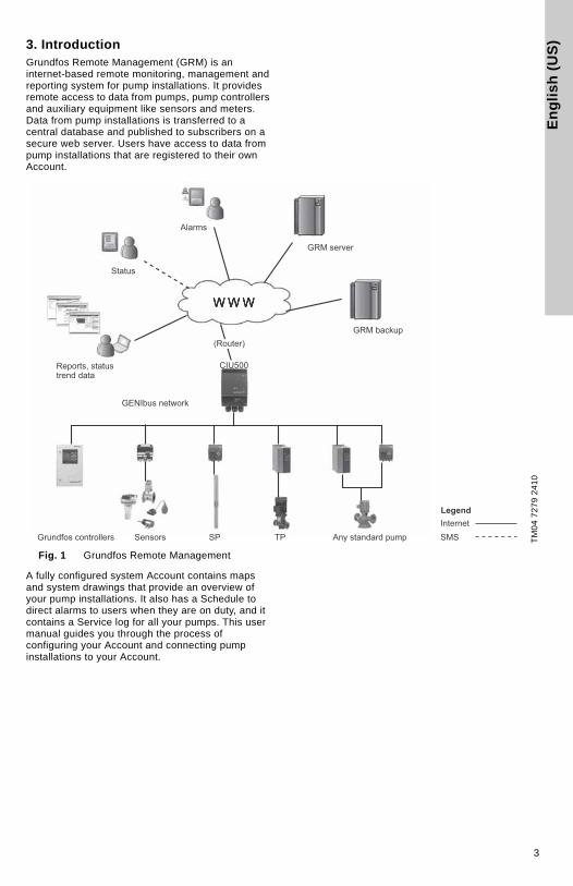
3. IntroductionGrundfos Remote Management (GRM) is an internet-based remote monitoring, management and reporting system for pump installations. It provides remote access to data from pumps, pump controllers and auxiliary equipment like sensors and meters. Data from pump installations is transferred to a central database and published to subscribers on a secure web server. Users have access to data from pump installations that are registered to their own Account.
Fig. 1 Grundfos Remote Management
A fully configured system Account contains maps and system drawings that provide an overview of your pump installations. It also has a Schedule to direct alarms to users when they are on duty, and it contains a Service log for all your pumps. This user manual guides you through the process of configuring your Account and connecting pump installations to your Account.
TM
04
72
79
24
10
Alarms
GRM server
GRM backup
GENIbus network
Grundfos controllers Sensors SP TP Any standard pump
Reports, statustrend data
Status
CIU500
(Router)
LegendInternetSMS
3

En
glis
h (U
S)
A fully configured Grundfos Remote Management system appears from fig. 2.
Fig. 2 Example of an Account in Grundfos Remote Management
In the following, the tabs at the top of the user interface will be described in the order that the system is to be set up.
To get started using the system, we recommend you to read these instructions and carefully follow the setup procedure.
Other relevant documentation
Separate installation and operating instructions are available for the hardware:
• CIM 500 Ethernet module: http://net.grundfos.com/qr/i/98407037
• CIU 500 Communication Interface Unit: http://net.grundfos.com/qr/i/96846337
• CIU 500 Communication Interface Unit (quick guide): http://net.grundfos.com/qr/i/96846333
• Multi-purpose IO module: http://net.grundfos.com/qr/i/98470828
The functionality of Grundfos Remote Management is continually improved and enhanced. Information about new features is found online in the system.
This manual contains all the information you need for initial setup of your user Account in Grundfos Remote Management.
TM
04
72
80
24
10
Note
We recommend you not to use Grundfos Remote Management as the only means of monitoring and control in systems where malfunction for a short period of time has severe consequences. The system is never more reliable than the network used for data communication.
4
En
gli
sh
(U
S)
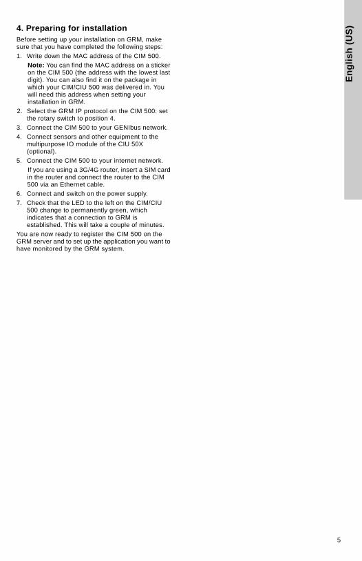
4. Preparing for installationBefore setting up your installation on GRM, make sure that you have completed the following steps:
1. Write down the MAC address of the CIM 500.
Note: You can find the MAC address on a sticker on the CIM 500 (the address with the lowest last digit). You can also find it on the package in which your CIM/CIU 500 was delivered in. You will need this address when setting your installation in GRM.
2. Select the GRM IP protocol on the CIM 500: set the rotary switch to position 4.
3. Connect the CIM 500 to your GENIbus network.
4. Connect sensors and other equipment to the multipurpose IO module of the CIU 50X (optional).
5. Connect the CIM 500 to your internet network.
If you are using a 3G/4G router, insert a SIM card in the router and connect the router to the CIM 500 via an Ethernet cable.
6. Connect and switch on the power supply.
7. Check that the LED to the left on the CIM/CIU 500 change to permanently green, which indicates that a connection to GRM is established. This will take a couple of minutes.
You are now ready to register the CIM 500 on the GRM server and to set up the application you want to have monitored by the GRM system.
5

En
glis
h (U
S)
5. Log-on to the GRMTo log on to the GRM server system, go to
https://remotemanagement.grundfos.com.
You will be prompted for user name and password.
Current users of the Grundfos Extranet can log on with their Extranet user name and password. New users will receive an e-mail with log-on details.
If you do not have a user name and a password, contact your local Grundfos company, or send an e-mail to [email protected].
When you log on for the first time, a navigation tree will appear. See fig. 3.
The basic steps in setting up an Account are described in the following section.
5.1 Navigation
To provide an overview of the installations monitored by the GRM system, a navigation tree is used.
Fig. 3 Navigation tree
The navigation tree is divided into three levels:
5.1.1 Account level
At the Account level, you will find the name and details of your Account.
5.1.2 Section level
At the Section level, it is possible to create several Sections. Sections are logical groups of one or more Installations.
At the Installation level, you will find the devices that are monitored. An Installation is defined by a modem monitoring one or more bus devices or sensors.
Adding a Section
Right-click the Account name, and click Add to add a Section.
Fig. 4 Adding a Section
When the Section is created, you can add an Installation to the Section.
5.1.3 Installation level
An Installation is always added to a Section and consists of a communication device and a number of monitored devices, normally a CIM 500 and at least one GENIbus device (Grundfos pump, pump controller or IO module).
Adding an Installation
Right-click the Section name, and click Add to add an Installation.
Fig. 5 Adding an Installation
The setup of an Installation is a four-step procedure:
1. Create Installation.
2. Set up Installation.
3. Configure and connect Installation.
4. Configure alarms and warnings.
TM
04
72
82
24
10
Pos. Level
1 Account
2 Section
3 Installation
1
2
3
Note
Sections could, for example, reflect a geographical segmentation of the entire monitored network or segmentation according to area of expertise or responsibility of a group of persons.
TM
04
72
83
24
10
TM
04
72
84
24
10
6

En
gli
sh
(U
S)
Step 1: Create Installation• Select "Register a new Grundfos CIM 500 or CIU 50X based Communication Device".
Fig. 6 Registering a communication device
• Enter the MAC address of the CIM 500
Fig. 7 Entering the MAC address
• Click "Test connection". The test will take a few minutes. The server configures the CIM interface for use in the GRM system.
If the server has connected successfully, you are notified and can proceed to Step 2: Name and type.
If the server does not get a response from the CIM interface within two minutes, the attempt to connect will time out, and you will get a fault notification. See section 17. Fault finding.
Step 2: Name and type
Enter a name for your Installation, and select the application type that best characterizes the Installation. This will provide the system with information on, for example, the type of report that is relevant for this Installation.
Fig. 8 Name and type of installation
TM
06
47
66
29
15
TM
06
47
67
29
15
TM
04
72
86
24
10
7
En
glis
h (U
S)
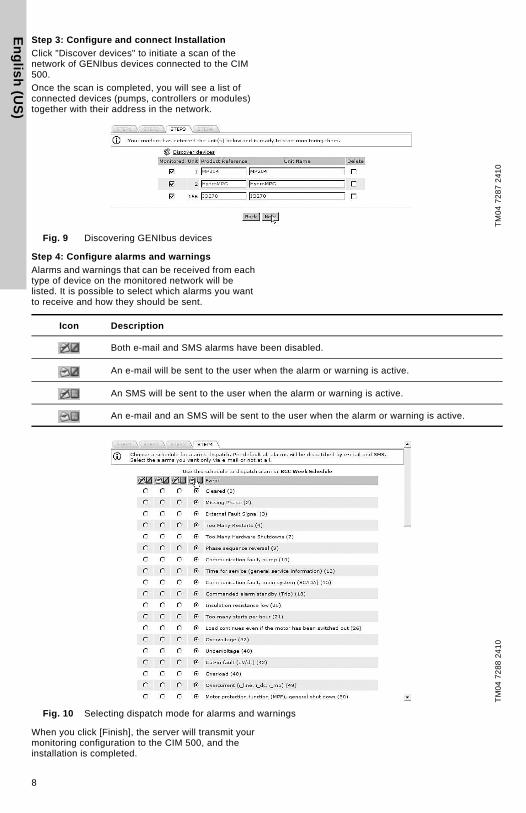
Step 3: Configure and connect Installation
Click "Discover devices" to initiate a scan of the network of GENIbus devices connected to the CIM 500.
Once the scan is completed, you will see a list of connected devices (pumps, controllers or modules) together with their address in the network.
Fig. 9 Discovering GENIbus devices
Step 4: Configure alarms and warnings
Alarms and warnings that can be received from each type of device on the monitored network will be listed. It is possible to select which alarms you want to receive and how they should be sent.
Fig. 10 Selecting dispatch mode for alarms and warnings
When you click [Finish], the server will transmit your monitoring configuration to the CIM 500, and the installation is completed.
TM
04
72
87
24
10
Icon Description
Both e-mail and SMS alarms have been disabled.
An e-mail will be sent to the user when the alarm or warning is active.
An SMS will be sent to the user when the alarm or warning is active.
An e-mail and an SMS will be sent to the user when the alarm or warning is active.
TM
04
72
88
24
10
8

En
gli
sh
(U
S)
6. GRM data communicationThis section describes how data communication and data collection work in Grundfos Remote Management.
We distinguish between four different types of data:
Data type Description
Sample Data
Sample data is used to create trend curves and reports.It is stored in the CIM 500 and sent every 30 minutes to the server. Sample data can be minimum, maximum and average value of system characteristics, such as flow, head, temperature, etc.
Event DataEvent Data is real-time data. This data tells you what is going on in the installation right now.Event Data is collected and displayed when you establish a connection to the installation. It is updated approximately every 5 minutes.
Alarm DataAlarm Data is a special type of Event Data. When a CIM 500 sends an alarm to the central server, it will also deliver a snapshot of Event Data present for that installation at the time the event occurred.
Manage Commands
You can send configuration and control commands to a GENIbus device directly via the GRM user interface.
9

En
glis
h (U
S)
7. Overview
Fig. 11 Overview
In this view, it is possible to insert images at Account and Section levels, for example maps and system drawings displaying the location and layout of pump installations.
Supported formats are *.png, *.jpg and *.gif. We recommend file sizes below 250 kb to optimize the performance of the web server. Largest permissible file size is 10 Mb.
Fig. 12 Uploading an image and placing Sections on the imageT
M0
4 7
28
9 2
41
0T
M0
4 7
29
1 2
41
0
10

En
gli
sh
(U
S)
8. Schedule for alarm distributionFig. 13 Schedule
One of the key features of GRM is the ability to distribute alarms from monitored pumps and controllers according to a centrally maintained Schedule.
The distribution of alarms from the GRM server is based on Week Schedules and alarm teams. It is possible to create any number of Week Schedules in the system.
Once the Week Schedule has been assigned to a Section, all alarms and warnings from Installations in that Section will be distributed to users according to the assigned Schedule.
The first thing to do is to create your alarm team(s).
Fig. 14 Alarm team
TM
04
72
92
24
10
Note A Week Schedule is not active until it has been assigned to a Section.
TM
04
72
93
24
10
11

En
glis
h (U
S)
To assign a Week Schedule to a Section, right-click the Section name, and select the Week Schedule from the drop-down list.
Fig. 15 Assigning a Week Schedule
Fig. 16 Example of Week Schedule
All GRM users are potential members of an alarm team. Users that have entered a mobile phone number on their Account details are able to receive alarms via SMS.
If there is no mobile phone number registered for a user, the e-mail address is the only way of delivering alarms.
TM
04
72
94
24
10
TM
04
72
96
24
10
Note
You can make as many Week Schedules as you like. They are not activated until you assign them to a Section.
Different Sections may operate on different Week Schedules.
12
En
gli
sh
(U
S)
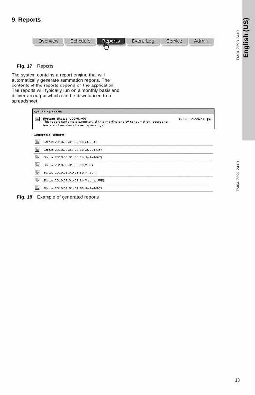
9. ReportsFig. 17 Reports
The system contains a report engine that will automatically generate summation reports. The contents of the reports depend on the application. The reports will typically run on a monthly basis and deliver an output which can be downloaded to a spreadsheet.
Fig. 18 Example of generated reports
TM
04
72
98
24
10
TM
04
72
99
24
10
13

En
glis
h (U
S)
10. Event log
Fig. 19 Event log
The Event log provides a full history of events and interactions related to each monitored device.
The Event log provides a record of the following:
• alarms
• warnings
• cleared alarms and warnings
• user acknowledgement of alarms and warnings
• remote-control commands issued by a user
• service warnings
• comments entered manually by a user.
All events are time-stamped when they are received by the server, and user-initiated events are stamped with the user’s system ID. The Event log can be downloaded to a spreadsheet.
Fig. 20 Event log
TM
04
73
00
24
10
TM
04
73
01
24
10
14

En
gli
sh
(U
S)
11. ServiceFig. 21 Service
The Service tab provides a tool to manage service of pump installations. The basic functionality keeps track of the total number of operating hours for each of the pumps monitored by the system. For some products, the number of starts is also monitored.
You can set thresholds for each service parameter and be notified automatically via e-mail when a threshold is met. It is also possible to set a date on which you want to be notified if your service strategy is based on a time interval.
When a new pump is detected by the CIM interface, an entry for that pump is automatically created under the Service tab.
If you enter the product number of the monitored Grundfos pump, you will have direct online access to documentation, including service videos, pump curves, etc.
Fig. 22 Example of a Service log entry
TM
04
73
02
24
10
TM
04
73
03
24
10
15
En
glis
h (U
S)
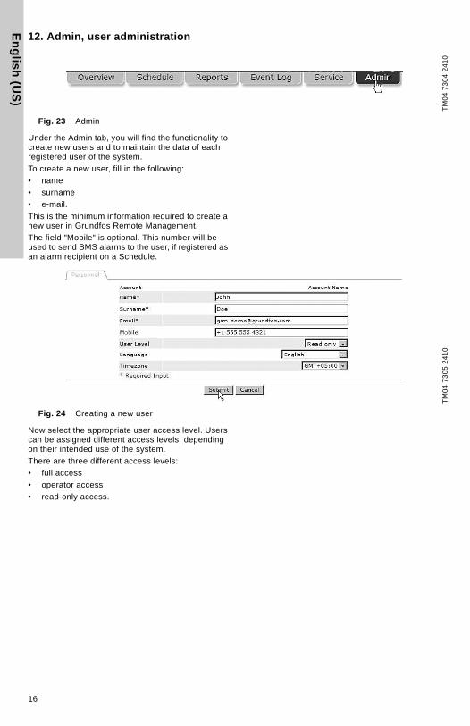
12. Admin, user administration
Fig. 23 Admin
Under the Admin tab, you will find the functionality to create new users and to maintain the data of each registered user of the system.
To create a new user, fill in the following:
• name
• surname
• e-mail.
This is the minimum information required to create a new user in Grundfos Remote Management.
The field "Mobile" is optional. This number will be used to send SMS alarms to the user, if registered as an alarm recipient on a Schedule.
Fig. 24 Creating a new user
Now select the appropriate user access level. Users can be assigned different access levels, depending on their intended use of the system.
There are three different access levels:
• full access
• operator access
• read-only access.
TM
04
73
04
24
10
TM
04
73
05
24
10
16

En
gli
sh
(U
S)
Full accessA full-access user has access to all features of the system, for example to view the following:
• current status of the system
• trend curves
• reports
• event log
• service log.
A full-access user can operate the system via remote access, i.e.
• reset the system
• perform remote start/stop
• change settings
• manage administration rights.
A full-access user can create, change or delete a Section, an Installation, a user Account, etc.
We recommend you only to have one or two full-access users.
Operator access
An operator is able to remote-control installations, for example perform the following:
• remote resetting
• remote start/stop of a pump
• change of setpoint for system pressure.
Operators are users that you would normally also trust with physical access to the monitored systems.
Read-only access
Read-only users can view the following:
• current status of the system
• trend curves
• reports
• event log
• service log.
This group of users cannot change settings and affect the operation of an installation.
Read-only users would normally access the system in order to analyze the performance. Users who are intended to receive SMS alarms only, not to access the system, should be created as read-only users.
Language
Select the user’s preferred language from the list of available languages.
Time zone
Enter the time zone in which an alarm schedule is used. This feature of the system makes it easy to work with alarm teams in different time zones.
Observe the following:
• Place Installations in the same time zone in the same folder.
• Set the right time zone for the alarm schedule you assign to the Section.
If you do not operate with service teams across different time zones, just use the default setting.
13. AlarmsBy default the CIM interface will transmit alarms generated by a monitored GENIbus device to the central server. There are, however, also some other alarms available.
13.1 Heartbeat
The alarm text "Communication fault, missing heartbeat" is a server-generated alarm message that informs you that a CIM interface has failed to routinely contact the central server.
Recommended actions to take when this alarm is received:
1. Log on to the GRM, and attempt to connect to the Installation.
2. Check the status of the Ethernet connection on the port of your CIM 500 and any connected router or network device.
3. Check the power supply to the installation.
17
En
glis
h (U
S)
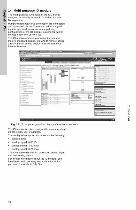
14. Multi-purpose IO moduleThe multi-purpose IO module in the CIU 50X is designed especially for use in Grundfos Remote Management.
Pumps without GENIbus connection are connected and monitored via the IO module. When a digital input is specified to monitor a pump during configuration of the IO module, a pump log will be created under the Service tab.
The IO module enables you to monitor sensors, meters, standard pumps, etc. and to remote-control a relay and an analog output (0-10 V) from your internet browser.
Fig. 25 Example of graphical display of monitored sensors
The IO module has two configurable inputs (analog/digital) set by use of jumpers.
The configurable inputs can be set as the following:
• digital signal
• analog signal (0-10 V)
• analog signal (4-20 mA)
• analog signal (0-20 mA).
The IO module has one Pt100/Pt1000 sensor input and one analog output.
For further information about the IO module, see installation and operating instructions for Multi-purpose IO module in CIU 50X.
TM
04
74
40
24
10
18

En
gli
sh
(U
S)
Once you are online with your application, you canperform the following actions:
• Set up names for all input types.
• Scale information for the analog inputs.
• Set alarm thresholds for analog inputs.
• Define digital inputs for alarm detection.
• Define digital inputs to count pulse signals.
• Define digital inputs to monitor operations, i.e. log operating hours and number of starts of a connected pump.
On the basis of the above definitions, a graphical user interface is generated complete with the option of seeing trend data for the monitored I/O devices.
Fig. 26 Example of graphical display of data from monitored sensors
GENIbus I/O modules are available from Grundfos if you should need additional I/O functionality.
TM
04
74
41
24
10
19

En
glis
h (U
S)
15. Ethernet LED on CIM/CIU 500 (left)
LED status Location Description
Flashing red No connection to GRM.
Flashing greenStartup period (120 sec). The CIM 500 initiates communication with GRM.
Permanently green Connection to GRM established.
Flashing green... ... ... ... (3-second intervals)
Data transmitting to GRM server.
20

En
gli
sh
(U
S)
16. GENIbus LED of the CIM/CIU500 (right)17. Fault finding
18. DisposalThis product or parts of it must be disposed of in an environmentally sound way:
1. Use the public or private waste collection service.
2. If this is not possible, contact the nearest Grundfos company or service workshop.
Subject to alterations.
LED status Location Description
CIM 500 (factory default).Permanently red LED.
• The CIM 500 has not been connected to any GENIbus device yet.
The CIM 500 has loaded a GENIbus device, but there is a problem on the GENIbus network.Red LED:. . . . (1-second intervals)
• A GENIbus device expected by the CIM 500 has been removed, switched off or its address has been changed.
• There is a cable or connector problem on the GENIbus network.
• The device detected is not supported by the CIM 500.
The GENIbus network is configured correctly.Permanently green LED.
GENIbus status OK.
Fault Possible cause Remedy
1. No response from the CIM 500
a) The CIM 500 is not connected to a 3G/4G Router
Check Cables, Router, power supply
b) The 3G/4G Router is not configured
Check 3G/4G Router setup
c) The SIM card is not put into Router
Check that SIM card is put in proper into Router and PIN code is empty
d) You have not entered a correct MAC address
You can find the MAC address on a sticker on the CIM 500 (the address with the lowest last digit).
e) No communication Follow instruction manuals of CIM 500 and your Router
21

22

Gru
nd
fos
com
pan
iesGRUNDFOS Kansas City
17100 West 118th TerraceOlathe, Kansas 66061Phone: (913) 227-3400Fax: (913) 227-3500
www.grundfos.us
GRUNDFOS Canada2941 Brighton Road Oakville, Ontario L6H 6C9 CanadaPhone: +1-905 829 9533Telefax: +1-905 829 9512
www.grundfos.ca
GRUNDFOS MéxicoBoulevard TLC No. 15Parque Industrial Stiva AeropuertoC.P. 66600 Apodaca, N.L. MéxicoPhone: 011-52-81-8144 4000Fax: 011-52-81-8144 4010
www.grundfos.mx

98963177 1015
ECM: 1168732
www.grundfos.com
The
nam
e G
run
dfos
, the
Gru
ndf
os lo
go, a
nd
be
thin
k in
no
vate
are
reg
iste
red
trad
emar
ks
own
ed b
y G
rund
fos
Ho
ldin
g A
/S o
r G
run
dfos
A/S
, Den
mar
k. A
ll rig
hts
rese
rved
wo
rldw
ide.
© C
opyr
ight
Gru
ndfo
s H
oldi
ng A
/S


![GRUNDFOS ALPHA+net.grundfos.com/Appl/ccmsservices/public/... · Uputstvo za montažu i upotrebu 170 ... uct GRUNDFOS ALPHA+, to which this declaration relates, is in ... [°C] Liquid](https://img.dokumen.tips/doc/110x75/5e50725de29b1a0feb3efab8/grundfos-alphanet-uputstvo-za-montau-i-upotrebu-170-uct-grundfos-alpha.jpg)