Embed Size (px)
Citation preview
Tech. Specification NESCO Utility/ CT,PT & VCB/12/01.08.16 Page 1
SECTION –IV
TECHNICAL SPECIFICATION OF
11KV /33KV CT & PT
“GROUP – A”
TENDER N O T I C E NO- NESCO Utility/ CT , PT & VCB / 12/ 8558 Date: 01.08.16
Tech. Specification NESCO Utility/ CT,PT & VCB/12/01.08.16 Page 2
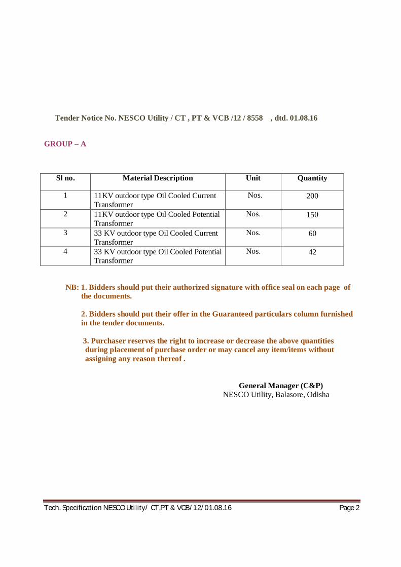
Tender Notice No. NESCO Utility / CT , PT & VCB /12 / 8558 , dtd. 01.08.16
GROUP – A
Sl no. Material Description Unit Quantity
1 11KV outdoor type Oil Cooled Current Transformer
Nos. 200
2 11KV outdoor type Oil Cooled Potential Transformer
Nos. 150
3 33 KV outdoor type Oil Cooled Current Transformer
Nos. 60
4 33 KV outdoor type Oil Cooled Potential Transformer
Nos. 42
NB: 1. Bidders should put their authorized signature with office seal on each page of the documents.
2. Bidders should put their offer in the Guaranteed particulars column furnished
in the tender documents. 3. Purchaser reserves the right to increase or decrease the above quantities during placement of purchase order or may cancel any item/items without assigning any reason thereof .
General Manager (C&P) NESCO Utility, Balasore, Odisha
Tech. Specification NESCO Utility/ CT,PT & VCB/12/01.08.16 Page 3
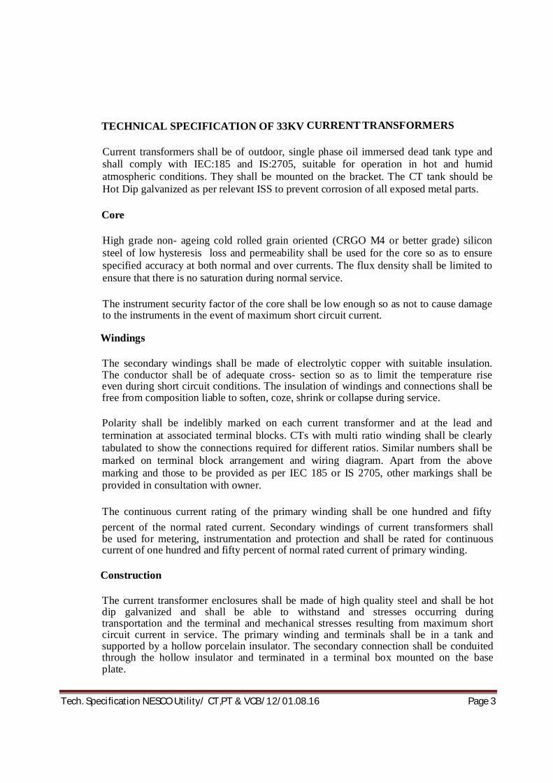
TECHNICAL SPECIFICATION OF 33KV CURRENT TRANSFORMERS
Current transformers shall be of outdoor, single phase oil immersed dead tank type and shall comply with IEC:185 and IS:2705, suitable for operation in hot and humid atmospheric conditions. They shall be mounted on the bracket. The CT tank should be Hot Dip galvanized as per relevant ISS to prevent corrosion of all exposed metal parts.
Core
High grade non- ageing cold rolled grain oriented (CRGO M4 or better grade) silicon steel of low hysteresis loss and permeability shall be used for the core so as to ensure specified accuracy at both normal and over currents. The flux density shall be limited to ensure that there is no saturation during normal service.
The instrument security factor of the core shall be low enough so as not to cause damage to the instruments in the event of maximum short circuit current.
Windings
The secondary windings shall be made of electrolytic copper with suitable insulation. The conductor shall be of adequate cross- section so as to limit the temperature rise even during short circuit conditions. The insulation of windings and connections shall be free from composition liable to soften, coze, shrink or collapse during service.
Polarity shall be indelibly marked on each current transformer and at the lead and termination at associated terminal blocks. CTs with multi ratio winding shall be clearly tabulated to show the connections required for different ratios. Similar numbers shall be marked on terminal block arrangement and wiring diagram. Apart from the above marking and those to be provided as per IEC 185 or IS 2705, other markings shall be provided in consultation with owner.
The continuous current rating of the primary winding shall be one hundred and fifty percent of the normal rated current. Secondary windings of current transformers shall be used for metering, instrumentation and protection and shall be rated for continuous current of one hundred and fifty percent of normal rated current of primary winding.
Construction
The current transformer enclosures shall be made of high quality steel and shall be hot dip galvanized and shall be able to withstand and stresses occurring during transportation and the terminal and mechanical stresses resulting from maximum short circuit current in service. The primary winding and terminals shall be in a tank and supported by a hollow porcelain insulator. The secondary connection shall be conduited through the hollow insulator and terminated in a terminal box mounted on the base plate.

Tech. Specification NESCO Utility/ CT,PT & VCB/12/01.08.16 Page 4
Hermetic sealing Each current transformer shall be supplied filled with insulating oil complying with IEC:296 or IS:335 and shall be hermetically sealed to prevent atmosphere coming in contact with oil, avoiding frequent filtration and change of oil. Nitrogen or any oil inert gas above the oil level shall be provided to permit expansion and contraction of oil without any contract with the atmosphere.
The current transformers shall have provision for draining and re-filling insulation oil after drying.
Insulating oil
The Current transformer shall be complete with new insulating oil. The quantity of insulating oil for first filling of the equipment and complete specification of oil proposed to be used shall be stated in the bid. The oil shall conform to the requirements of latest issue of IEC:296 or IS:335.
Fittings and accessories
Fittings and accessories listed below shall be supplied with each current transformer:
o Oil level gauge
o Oil filling hole and cap;
o Pressure relief device;
o HV terminal connectors;
o Two earthing terminals and strips with necessary nut, bolts and washers;
o Name and rating plate;
o Terminal box with LV terminal connections;
o Mounting nuts, bolts and washers;
Any other fittings deemed essential by the Supplier shall also be supplied with each current transformer.
The oil level gauge shall be mounted in such a way that the oil level can be clearly seen from ground level.
A dust, vermin and weather proof terminal box shall be provided at the lower end of the current transformer for terminating the secondary windings. The box shall have a bolted cover plate complete with gaskets. The terminal box shall have terminal blocks, cable gland plate and cable glands with shrouds suitable for different sizes of PVC insulated control cables 650/1100V grade as per IEC:227 or IS:1554. The terminal blocks shall

Tech. Specification NESCO Utility/ CT,PT & VCB/12/01.08.16 Page 5
have covering of moulded insulation materials complete with brass studs, washers, nuts and lock nuts suitable for termination of 2X2.5 sqmm wires. The termination shall be made by crimping lugs or bare wire with insulating sleeves at ends.
The terminal box enclosure shall have protection as per class IP 55 as defined in IEC:529 or IS:13947.
CT Junction Box/Console Box
Each set of 3 current transformers for three phase shall be provided with a common junction box mounted on the circuit breaker supporting structure at a convenient position to accommodate the secondary wire of CT and other control cables of Purchaser. Separate terminals for testing the relays and instruments and short circuiting of each current transformer secondary wires shall be provided in it. The junction box enclosure shall have the same protection features as for the terminal box. It shall be provided with terminal blocks, gland plates and glands suitable for different sizes of cables. Facilities shall be provided for earthing the CT secondary wires in the junction box.
Hollow porcelain insulators
The insulators of the current transformers shall conform to latest edition of IS:5621 and shall be subjected to and successfully pass the tests listed in this standard and in IEC:233. The hollow porcelain insulators shall be brown glazed and shall meet the requirements indicated in this specification. The insulators shall be cemented with Portland cement to the flanges resulting in high mechanical, tensile and breaking strength.
Insulation level
The current transformers shall be designed to withstand impulse test voltages and power frequency test voltages as specified in this specification.
Terminal connections
The CTs shall be provided with bi-metallic solderless clamp and rigid type terminal connectors on the top tank for connection to the HV terminals. The other requirements shall be same as for the terminal connectors of the circuit breaker described in this specification. They shall be universal type suitable for both horizontal and vertical connections. Two earthing terminals complete with necessary hardware shall be provided on each CT for connecting to earth continuity conductor to be provided. The earthing terminals shall be identified by means of appropriate symbol marked in a legible and indelible manner adjacent to the terminals. The terminals shall be adequately sized to meet the full earth fault current envisaged.

Tech. Specification NESCO Utility/ CT,PT & VCB/12/01.08.16 Page 6
Basic technical requirement Ratings: The CTs shall conform to the following ratings and other particulars of the circuit breakers:
Technical Requirements – For 2 Core CT
Sl. No
Particulars
Requirements
1 Function
For 33 KV Feeder control in 33/11 KV primary substations.
2 Requirement
Core-1:Instrumentation and Metering Core-2:Combined over current and earth fault protection
3 Transformation Ratio
400-200-100 /1-1 A
4 Rated Burden (VA)
Core:1:15 Core:2:15
5 Class of Accuracy
Core- 1:0.5 Core- 2:5P
6 Instrument Security Factor
Core-1 < 5
7 Accuracy Limit Factor
Core-2 : 20
8 Rated Voltage
36KV
9 Short Time Rating
31KA rms for 3 seconds
10 Creepage distance Protected creepage distance
900mm minimum 450mm minimum
11 Insulation Level: -Impulse Voltage1.2/50 s wave withstand level -Power frequency 1 min voltage withstand level
170KV
70KV
Tests and inspection The CTs shall be tested in accordance with the requirements of the type tests and routine tests as per the latest issues IEC:185 or IS:2705. The tests to be conducted shall include:

Tech. Specification NESCO Utility/ CT,PT & VCB/12/01.08.16 Page 7
Type Tests: o Lightning impulse voltage;
o Power frequency wet withstand voltage ;
o Temperature rise;
o Short time current;
o Composite error;
o Accuracy test (for measuring core);
o Instrument security current (for measuring core);
o Current error and phase displacement (for protection core) Routine tests
i. Verification of terminal marking and polarity;
ii. Power frequency dry withstand test on primary windings;
iii. Power frequency dry withstand test on secondary windings;
iv. Power frequency dry withstand test between sections;
v. Over voltage inter-turn test;
vi. Composite error;
vii. Turn ratio;
viii. Accuracy test (for measuring core);
ix. Current error and phase displacement (for protection core);
x. Knee point voltage and magnetizing current test (for PS class);
xi. Secondary winding resistance (for PS class).
xii. Insulation Resistance Test.

Tech. Specification NESCO Utility/ CT,PT & VCB/12/01.08.16 Page 8
TECHNICAL SPECIFICATION OF 33KV POTENTIAL TRANSFORMERS BASIC TECHNICAL REQIREMENTS
The 33KV outdoor voltage transformers are required to meet the following basic technical requirements (Reference standards: IEC:186, IS:3156 and associated standards listed in the specification):
Sl. No
Particulars
Requirements
1 Type
Single phase
2 Nominal system voltage, phase to phase
33KV
3 Application
Instrumentation, Metering and Protection
4 Number of secondary windings
1
5 Rated normal burden*
200VA
6 Rated primary voltage
33KV/ √ 3
7 Rated secondary voltage
110V/ √ 3
8 Class of accuracy
0.5
9 Rated insulation level: (Primary winding) (Phase to earth)
i) One minute power frequency withstand voltage to earth (wet and dry) rms
70KV
ii) Impulse withstand voltage to earth with 1.2/50 sec wave of +ve and –ve polarity (peak)
170KV
10 One minute power frequency withstand voltage of secondary winding (rms)
i) Between phase to earth
3KV
ii) Between sections
3KV

Tech. Specification NESCO Utility/ CT,PT & VCB/12/01.08.16 Page 9
11 Rated voltage factor
i) Continuous
1.2
ii) For 30 seconds
1.5
12 Creepage distance to earth in mm per KV of highest phase to phase system voltage
25
* The burden indicated is the minimum acceptable to the Employer. The Contractor shall ensure that the rated output of the voltage transformers are adequate to meet at least 120 percent of the connected load (burden). GENERAL The voltage transformers to be supplied under this specification shall be of outdoor, single phase dead tank double wound, oil immersed type, complying with IEC:185 and IS:3156 suitable for operation in hot and humid atmospheric conditions. To prevent corrosion of the exposed surfaces, the tank should be not dip galvanized. They shall have separate HV and LV windings and shall be suitable for use as bus VTs in 33/11KV primary substations. Duty requirement 33KV Voltage transformer for all the indicating instruments and measuring meters in the primary substation on 33KV side. Porcelain Insulator External parts of the voltage transformers which are under continuous electrical stress shall be of hollow porcelain insulators complying with latest edition of IS:6521 tested as per IEC:233. The creepage and flashover distance of the insulators shall be dimensioned and the type and profile designed in accordance with IEC:815 or IS:13134 and shall be suitable for the worst environmental conditions for heavily polluted atmosphere and shall be not less than 25mm per KV of highest phase to phase system voltage with protected creepage distance minimum 50 percent of the total. Internal surfaces of hollow insulators shall also be glazed. The insulators shall be cemented with Portland cement to the flanges resulting in high mechanical, tensile and breaking strength. All porcelain used on the voltage transformers shall have the following properties high strength, homogeneity, uniform glaze, free from cavities and other flaws and a high quality uniform finish porcelain components shall withstand the maximum expected static and dynamic loads to which the voltage transformers may be subjected during their service life. The insulation of the hollow porcelain insulators shall be coordinated with that of the voltage transformers to ensure that any flash over occurs only externally. Core
Tech. Specification NESCO Utility/ CT,PT & VCB/12/01.08.16 Page 10
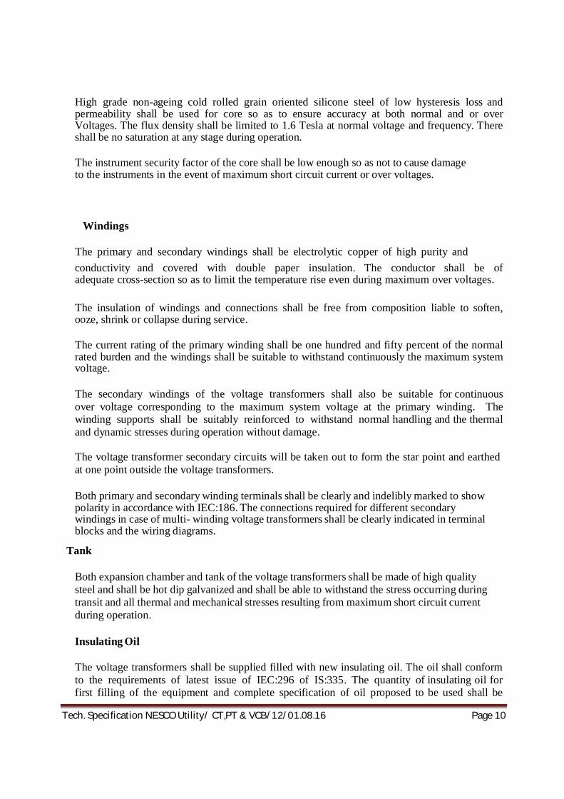
High grade non-ageing cold rolled grain oriented silicone steel of low hysteresis loss and permeability shall be used for core so as to ensure accuracy at both normal and or over Voltages. The flux density shall be limited to 1.6 Tesla at normal voltage and frequency. There shall be no saturation at any stage during operation. The instrument security factor of the core shall be low enough so as not to cause damage to the instruments in the event of maximum short circuit current or over voltages.
Windings The primary and secondary windings shall be electrolytic copper of high purity and conductivity and covered with double paper insulation. The conductor shall be of adequate cross-section so as to limit the temperature rise even during maximum over voltages. The insulation of windings and connections shall be free from composition liable to soften, ooze, shrink or collapse during service. The current rating of the primary winding shall be one hundred and fifty percent of the normal rated burden and the windings shall be suitable to withstand continuously the maximum system voltage. The secondary windings of the voltage transformers shall also be suitable for continuous over voltage corresponding to the maximum system voltage at the primary winding. The winding supports shall be suitably reinforced to withstand normal handling and the thermal and dynamic stresses during operation without damage. The voltage transformer secondary circuits will be taken out to form the star point and earthed at one point outside the voltage transformers. Both primary and secondary winding terminals shall be clearly and indelibly marked to show polarity in accordance with IEC:186. The connections required for different secondary windings in case of multi- winding voltage transformers shall be clearly indicated in terminal blocks and the wiring diagrams.
Tank
Both expansion chamber and tank of the voltage transformers shall be made of high quality steel and shall be hot dip galvanized and shall be able to withstand the stress occurring during transit and all thermal and mechanical stresses resulting from maximum short circuit current during operation. Insulating Oil The voltage transformers shall be supplied filled with new insulating oil. The oil shall conform to the requirements of latest issue of IEC:296 of IS:335. The quantity of insulating oil for first filling of the equipment and complete specification of oil proposed to be used shall be

Tech. Specification NESCO Utility/ CT,PT & VCB/12/01.08.16 Page 11
stated in the bid. Hermetic Sealing The voltage transformers shall be supplied filled with insulating oil and shall be hermetically sealed to prevent atmosphere coming in contact with oil, avoiding filtration and change of oil. Nitrogen or other inert gas shall be provided above the oil surface to permit expansion and contraction of oil. Provision shall be made for draining and re- filling the insulating oil.
Fitting and Accessories Fittings and accessories listed below shall be supplied with each voltage transformer: i. Oil level gauge. ii. Oil drain, sampling and filling hole with cap; iii. Pressure relief device;
iv. HV terminals; v. Two earthing terminals with necessary nuts, bolts and washers; vi. Name and rating plate; vii. Secondary terminal box with LV terminal connections; viii. Mounting nuts, bolts and washers;
ix. L.V HRC cartridge fuses for the protection of secondary winding; Any other fitting
deemed essential by the contractor shall also be supplied along with each voltage transformer: The oil level gauge shall be mounted in such a way that the oil level can be clearly seen from the ground level. The name and rating plate shall contain all the particulars as provided in IEC:186 and also the name of the employer and year of manufacture. They shall comply with the clause termed label in this specification. SECONDARY TERMINAL BOX A dust, vermin and weather proof terminal box shall be provided at the lower end of each voltage transformer for terminating the secondary windings. The box shall have a bolted removable cover plate complete with gaskets. The terminal box shall have cable gland plate and cable glands with shrouds suitable for entry of 4 core x2.5mm2 PVC insulated control cables as per IEC:227 or IS:1554.
Tech. Specification NESCO Utility/ CT,PT & VCB/12/01.08.16 Page 12
For 33KV Voltage Transformer one 4 core 2.5mm2 The terminal box enclosure shall have protection of class IP 55 as defined in IEC:529 or IS:13947 and shall be painted or galvanized in accordance with specification of Surface Treatment.
Terminal blocks Terminal blocks of brass studs rated for 10 Amps continuous current, 650 Volt grade enclosed in moulded insulating materials shall be provided with adequate electrical clearance for terminating the secondary wiring and outgoing connections. The terminal blocks shall be suitable for termination of 2.5mm2 wires. The termination shall be made by crimping Jugs or bare wire with insulating sleeves at ends. All terminals must be marked with numbers and wire termination provided with numbered ferrules for identification. Fuse protection The secondary windings shall be protected by HRC cartridge fuses in fuse holder consisting of carriers and bases. The carriers and bases shall be of high grade flame retarding and non hygroscopic moulded insulating materials with hard glass surface. Each fuse shall be identified with engraved plastic label. Circuit diagram A durable copy of the circuit wiring diagram shall be affixed to the inner side of the terminal box cover. Labels shall be provided inside the cover to describe the functions of various items of equipments. TERMINATION The equipment shall be supplied with HV electrical connection terminals of a size and rating appropriate for all the duties, including overload duty specified for the equipment. The terminals shall be of the bi-metallic type, suitable for connection of all aluminium alloy conductor (AAAC) or aluminium conductor steel reinforced (ACSR). In general connections using palm type solderless sockets shall be preferred. The proposed method of connections shall be stated in the offer and shall be subject to approval by the Purchaser, NESCO. Where the terminals are of the clamp type, they shall be suitable for taking a range of conductors appropriate to the rating of the equipment. All nuts, bolts, washers and spring washers required to complete the connection shall be supplied with the equipment. EARTHING TERMINAL Two earthing terminals complete with necessary hardware shall be provided on each voltage transformer for connecting to earth continuity conductors of the Employer. They shall be of electroplated brass and of adequate size to carry the earth fault current. The earthing terminals shall be identified by means of appropriate symbol marked in a legible and indelible manner adjacent to the terminals.
Tech. Specification NESCO Utility/ CT,PT & VCB/12/01.08.16 Page 13
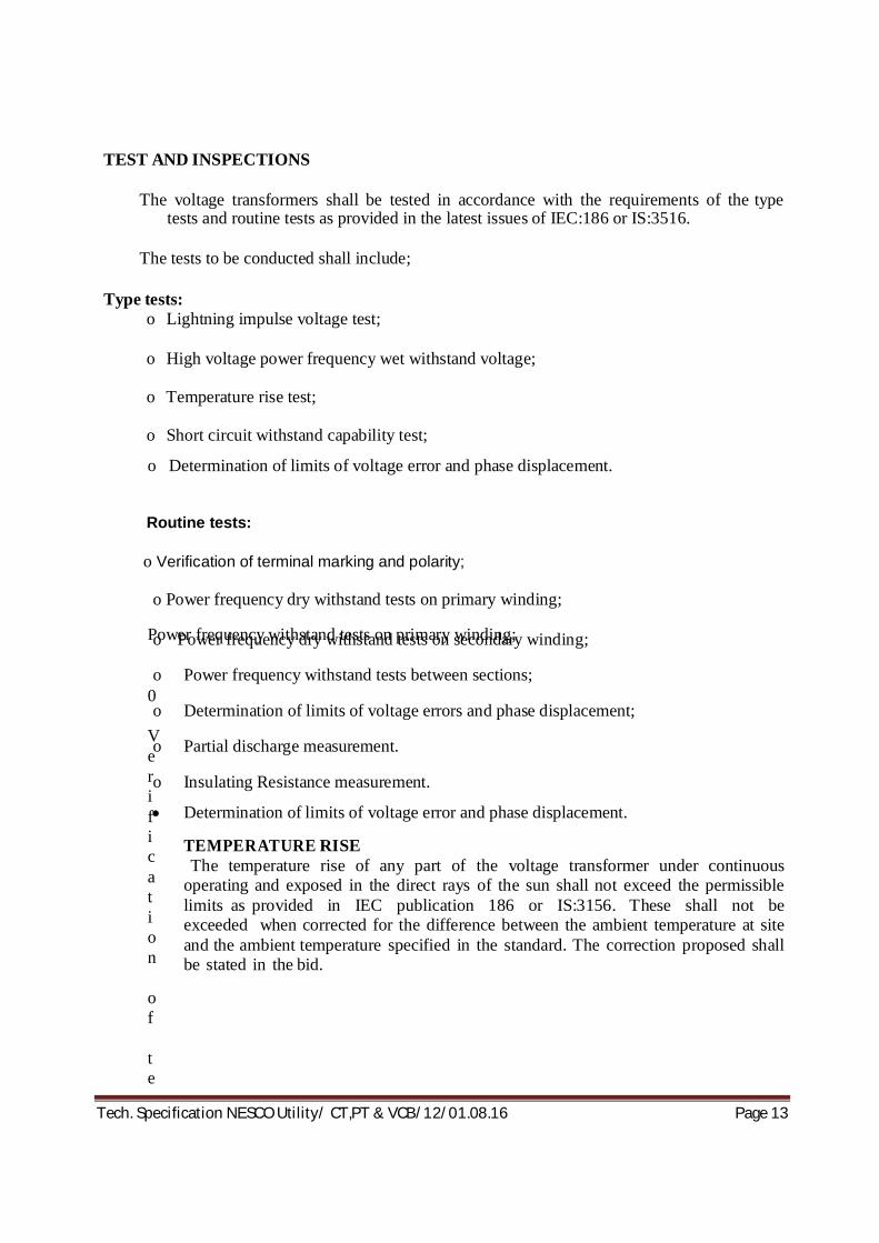
TEST AND INSPECTIONS
The voltage transformers shall be tested in accordance with the requirements of the type
tests and routine tests as provided in the latest issues of IEC:186 or IS:3516.
The tests to be conducted shall include; Type tests:
o Lightning impulse voltage test;
o High voltage power frequency wet withstand voltage;
o Temperature rise test;
o Short circuit withstand capability test; o Determination of limits of voltage error and phase displacement. Routine tests:
o Verification of terminal marking and polarity;
Power frequency withstand tests on primary winding;
0 Verification of te
o Power frequency dry withstand tests on primary winding; o Power frequency dry withstand tests on secondary winding;
o Power frequency withstand tests between sections;
o Determination of limits of voltage errors and phase displacement; o Partial discharge measurement. o Insulating Resistance measurement. Determination of limits of voltage error and phase displacement.
TEMPERATURE RISE The temperature rise of any part of the voltage transformer under continuous
operating and exposed in the direct rays of the sun shall not exceed the permissible limits as provided in IEC publication 186 or IS:3156. These shall not be exceeded when corrected for the difference between the ambient temperature at site and the ambient temperature specified in the standard. The correction proposed shall be stated in the bid.

14
TECHINICAL DATA SCHEDULE FOR 33 KV CURRENT TRANSFORMER
SL No.
DESCRIPTION As Per
Specification UNITS
BIDDER's OFFER
33KV CURRENT TRANSFORMER
Make of Manufacturer for transformer protection
Make and type of transformer
Outdoor, Oil-Cooled
(i)
Ratio 400-200-100/ 1- 1
Core1. Burden
15
VA
Accuracy class
0.5
Saturation factor
NA
Instrument security factor <5
Accuracy limit factor
Knee point voltage
5
Volts
Magnetizing current at Vk/2 Milli amps.
Secondary resistance Rct ≤ 2
ohms
Core 2. Burden
15
VA
Accuracy class
5P
Saturation factor
≤ 10
Accuracy limit factor
20
Short time current rating : Current
31
KA
Time 3 Sec. Impulse voltage
withstand level
170
KV
Power frequency voltage withstand level
Primary winding 70 KV Secondary winding 3 KV Specification of oil IS : 335
Quantity of oil 20-25 Liters
Creepage distance 900 mm
Protected creepage distance
450
mm

15
Tank (high grade steel) hot dip galvanized
Thickness 3 mm
Weight of CT complete with oil
kg
2 Corrosion Prevention System for CTs
Hot Dip Galvanised
Surface preparation Hot Dip Galvanised Rust in inhibition Hot Dip Galvanised Paint thickness As per IS micron Treatment of fasteners
Hot Dip Galvanised Oil resistance varnish For inside the tank
Drawing To be furnished by bidder
NB- Every CT should bear the marking of manufacturer’s name , Purchaser’s name , Sl. No., Rating etc.
Name & Signature of Bidder with seal

16
TECHINICAL DATA SCHEDULE FOR 33 KV POTENTIAL TRANSFORMER
SL No.
DESCRIPTION As Per
Specification Units
BIDDER's OFFER
33 KV VOLTAGE TRANSFORMER a. GENERAL.
Make
Type of transformer Single-Phase Outdoor, Oil-Cooled, Dead
Rated normal voltage 33 / √3 KV Rated maximum voltage 36 / √3 KV
Rated primary voltage
33 / √3
KV
Rated secondary voltage
110 / √3
Volts
V A burden 200 VA Accuracy class 0.5 Ratio error Minute Phase displacement
positive or negative
Saturation factor
Instrument security factor
Short time current rating
Rms value KV Period Sec Peak value KA Impulse voltage withstand
level
170
KV
One minute power frequency voltage withstand level of primary winding
70
KV
Specification of oil IS : 335
Weight of oil Kg Weight of core and
winding
Kg
Total weight Kg
Overall dimensions
Mm

17
Rated voltage factor
Continuous 1.2 For 30 seconds 1.5
Temperature rise above the ambient of 500C
40
0C
Correction factor
Partial discharge level pC
b. TANK Composition of metal
Hot Dip Galvanised
Thickness 3 mm
c. CORE Material composition CRGO Flux density at normal voltage and frequency
< 1.2
Telsa
Lamination thickness 0.27 mm d. WINDINGS
Purity of copper used Electrolytic copper Percent Type of insulation DPC Power frequency
withstand level
Secondary winding to earth
3
KV
Between sections 3 KV
e. SECONDARY TERMINAL
Degree of protection IP55 Vermin proof provision Yes/no
Weather proof provision Yes/no Dust proof provision Yes/no
Thickness of metal used mm
Overall dimensions mm Mounting arrangement
f. H V TERMINAL Material Bi-metallic or not Bi-Metallic Yes/no
Dimensions, mm
Size and type of conductor it can accommodate
Sq. mm
g. CORROSION PREVENTION SYSTEM
Hot Dip Galvanised
18
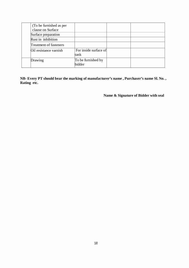
(To be furnished as per clause on Surface Treatment)
Surface preparation Rust in inhibition Treatment of fasteners
Oil resistance varnish For inside surface of tank
Drawing To be furnished by bidder
NB- Every PT should bear the marking of manufacturer’s name , Purchaser’s name Sl. No. , Rating etc.
Name & Signature of Bidder with seal

19
TECHNICAL SPECIFICATION FOR 11 KV CURRENT TRANSFORMER CURRENT TRANSFORMERS
11KV Current transformers shall be of outdoor, single phase oil immersed dead tank type and shall comply with IEC:185 and IS:2705, suitable for operation in hot and humid atmospheric conditions. They shall be mounted on the bracket. The CT tank should be Hot Dip galvanized as per relevant ISS to prevent corrosion of all exposed metal parts.
Core
High grade non- ageing cold rolled grain oriented (CRGO M4 or better grade) silicon steel of low hysteresis loss and permeability shall be used for the core so as to ensure specified accuracy at both normal and over currents. The flux density shall be limited to ensure that there is no saturation during normal service.
The instrument security factor of the core shall be low enough so as not to cause damage to the instruments in the event of maximum short circuit current.
Windings
The secondary windings shall be made of electrolytic copper with suitable insulation. The conductor shall be of adequate cross- section so as to limit the temperature rise even during short circuit conditions. The insulation of windings and connections shall be free from composition liable to soften core, shrink or collapse during service. Polarity shall be indelibly marked on each current transformer and at the lead and termination at associated terminal blocks. CTs with multi ratio winding shall be clearly tabulated to show the connections required for different ratios. Similar numbers shall be marked on terminal block arrangement and wiring diagram. Apart from the above marking and those to be provided as per IEC 185 or IS 2705, other markings shall be provided in consultation with owner.
The continuous current rating of the primary winding shall be one hundred and fifty percent of the normal rated current. Secondary windings of current transformers shall be used for metering, instrumentation and protection and shall be rated for continuous current of one hundred and fifty percent of normal rated current of primary winding.
Tank & Construction The current transformer enclosures shall be made of high quality steel and shall be hot dip galvanized and shall be able to withstand and stresses occurring during transportation and the terminal and mechanical stresses resulting from maximum short circuit current in service. The primary winding and terminals shall be in a tank and supported by a hollow porcelain insulator. The secondary connection shall be conduited through the hollow insulator and terminated in a terminal box mounted on the base plate.
Hermetic sealing
Each current transformer shall be supplied filled with insulating oil complying with IEC:296 or IS:335 and shall be hermetically sealed to prevent atmosphere coming in contact with oil, avoiding frequent filtration and change of oil. Nitrogen or any oil inert gas above the oil level shall be provided to permit expansion and contraction of oil without any contract with the atmosphere.

20
The current transformers shall have provision for draining and re-filling insulation oil after drying.
Insulating oil
The current transformer shall be complete with new insulating oil. The quantity of insulating oil for first filling of the equipment and complete specification of oil proposed to be used shall be stated in the bid. The oil shall conform to the requirements of latest issue of IEC:296 or IS:335.
Fittings and accessories
Fittings and accessories listed below shall be supplied with each current transformer:
Oil level gauge;
* Oil filling hole and cap;
* Pressure relief device;
* HV terminal connectors;
* Two earthing terminals and strips with necessary nut, bolts and washers;
* Name and rating plate;
* Terminal box with LV terminal connections; * Mounting nuts, bolts and washers Any other fittings deemed essential by the Supplier shall also be supplied with each current transformer.
The oil level gauge shall be mounted in such a way that the oil level can be clearly seen from ground level.
A dust, vermin and weather proof terminal box shall be provided at the lower end of the current transformer for terminating the secondary windings. The box shall have a bolted cover plate complete with gaskets. The terminal box shall have terminal blocks, cable gland plate and cable glands with shrouds suitable for different sizes of PVC insulated control cables 650/1100V grade as per IEC:227 or IS:1554. The terminal blocks shall have covering of moulded insulation materials complete with brass studs, washers, nuts and lock nuts suitable for termination of 2X2.5 sqmm wires. The termination shall be made by crimping lugs or bare wire with insulating sleeves at ends.
The terminal box enclosure shall have protection as per class IP 55 as defined in IEC:529 or IS:13947.
CT Junction Box/Console Box
Each set of 3 current transformers for three phase shall be provided with a common

21
junction box mounted on the circuit breaker supporting structure at a convenient position to accommodate the secondary wire of CT and other control cables of Purchaser. Separate terminals for testing the relays and instruments and short circuiting of each current transformer secondary wires shall be provided in it. The junction box enclosure shall have the same protection features as for the terminal box. It shall be provided with terminal blocks, gland plates and glands suitable for different sizes of cables. Facilities shall be provided for earthing the CT secondary wires in the junction box.
Hollow porcelain insulators
The insulators of the current transformers shall conform to latest edition of IS:5621 and shall be subjected to and successfully pass the tests listed in this standard and in IEC:233. The hollow porcelain insulators shall be brown glazed and shall meet the requirements indicated in this specification. The insulators shall be cemented with Portland cement to the flanges resulting in high mechanical, tensile and breaking strength.
Insulation level
The current transformers shall be designed to withstand impulse test voltages and power frequency test voltages as specified in this specification.
Terminal connections
The CTs shall be provided with bi-metallic solderless clamp and rigid type terminal connectors on the top tank for connection to the HV terminals. The other requirements shall be same as for the terminal connectors of the circuit breaker described in this specification. They shall be universal type suitable for both horizontal and vertical connections. Two earthing terminals complete with necessary hardware shall be provided on each CT for connecting to earth continuity conductor to be provided. The earthing terminals shall be identified by means of appropriate symbol marked in a legible and indelible manner adjacent to the terminals. The terminals shall be adequately sized to meet the full earth fault current envisaged.
Basic technical requirement
Ratings: The CTs shall conform to the following ratings and other particulars of the circuit breakers:
Technical Requirements Sl. No
Description
Requirements
1
Rated voltage
:
12 KV
2
Insulation level
:
a)
Impulse withstand voltage
:
75 KVP
b)
One minute power frequency with voltage on
:

22
i)
Primary winding
:
28KV rms
ii)
Secondary winding
:
3KV rms
3
Frequency
:
50Hz
4
Rated continuous thermal current
:
120% of rated primary current
5
Short time thermal rating and its duration
:
25KA for 3 sec.
6
Transformation ratio of CTs
i)
Category- A: 800-400-200/-1-1
Core-I Core-II
a)
Rated output
15VA 15VA
b)
Class of accuracy
0.5 5P
c)
Accuracy limit factor
- 20
d)
Purpose
Metering Protection
e)
Maximum exciting current at Vk/2
f)
Max. Instrument Security Factor
10 - -
7
Type
:
Single phase, outdoor, Dead tank, oil filled & hermetically sealed
Tests and inspection The CTs shall be tested in accordance with the requirements of the type tests and routine tests as per the latest issues IEC:185 or IS:2705.
The tests to be conducted shall include:
Type Tests: i) Lightning impulse voltage: ii) Power frequency wet withstand voltage; iii) Temperature rise; iv) Short time current; Composite error; v) Accuracy test (for measuring core); vi) Instrument security current (for measuring core); vii) Current error and phase displacement (for protection core)
Routine tests
i) Verification of terminal marking and polarity; ii) Power frequency dry withstand test on primary windings; iii) Power frequency dry withstand test on secondary windings;

23
iv) Power frequency dry withstand test between sections; v) Over voltage inter-turn test; vi) Composite error; vii) Turn ratio; viii) Accuracy test (for measuring core); ix) Current error and phase displacement (for protection core); x) Knee point voltage and magnetizing current test (for PS class); xi) Secondary winding resistance (for PS class) xii) Insulation Resistance Test.
24
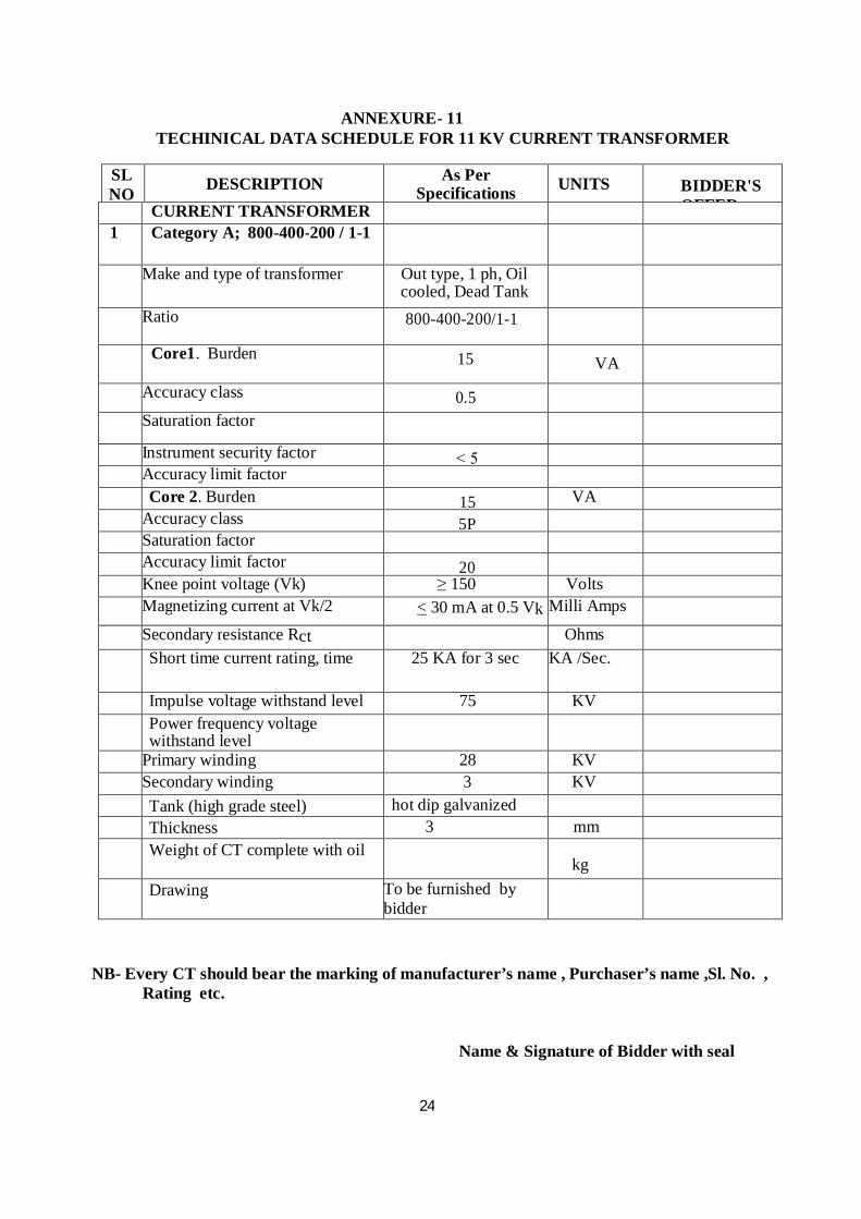
ANNEXURE- 11 TECHINICAL DATA SCHEDULE FOR 11 KV CURRENT TRANSFORMER
SL NO
DESCRIPTION As Per
Specifications
UNITS
BIDDER'S OFFER CURRENT TRANSFORMER
1 Category A; 800-400-200 / 1-1
Make and type of transformer Out type, 1 ph, Oil cooled, Dead Tank
Ratio 800-400-200/1-1
Core1. Burden 15 VA
Accuracy class 0.5
Saturation factor
Instrument security factor ˂ 5 Accuracy limit factor Core 2. Burden 15 VA Accuracy class 5P Saturation factor Accuracy limit factor 20 Knee point voltage (Vk) ≥ 150 Volts Magnetizing current at Vk/2 < 30 mA at 0.5 Vk Milli Amps
Secondary resistance Rct Ohms Short time current rating, time 25 KA for 3 sec KA /Sec.
Impulse voltage withstand level 75 KV Power frequency voltage
withstand level
Primary winding 28 KV Secondary winding 3 KV Tank (high grade steel) hot dip galvanized Thickness 3 mm Weight of CT complete with oil
kg
Drawing To be furnished by bidder
NB- Every CT should bear the marking of manufacturer’s name , Purchaser’s name ,Sl. No. , Rating etc.
Name & Signature of Bidder with seal

25
TECHNICAL SPECIFICATION FOR 11 KV POTENTIAL TRANSFORMER
BASIC TECHNICAL REQIREMENTS
The 11 KV outdoor voltage transformers are required to meet the following basic technical requirements (Reference standards: IEC:186, IS:3156 and associated standards listed in the specification):
Sl. No
Particulars
Requirements
1 Type Single phase, outdoor, oil filled & hermetically sealed
2 Nominal system voltage, phase to phase 11 KV 3 Application Instrumentation, Metering and Protection 4 Number of secondary windings 1 5 Rated normal burden* 100VA 6 Rated primary voltage 12 KV/√3 7 Rated secondary voltage 110V/√3 8 Class of accuracy 0.5 9 One min. power frequency withstand
voltage for primary 70 KV (rms)
10 One minute power frequency withstand voltage of secondary winding (rms)
3 KV (rms)
11 Rated voltage factor i) Continuous 1.2 ii) For 30 seconds 1.5 12 Creepage distance to earth in mm per KV of
highest phase to phase system voltage 25
* The burden indicated is the minimum acceptable to the Employer. The supplier shall ensure that the rated output of the voltage transformers is adequate to meet at least 120 percent of the connected load (burden).
GENERAL
The voltage transformers to be supplied under this specification shall be of outdoor, single phase dead tank double wound, oil immersed type, complying with IEC:185 and IS:3156 suitable for operation in hot and humid atmospheric conditions described in this document. To prevent corrosion of the exposed surfaces, the tank should be not dip galvanized. They shall have separate HV and LV windings and shall be suitable for use as bus VTs in 33/11KV primary substations.
Duty requirement
11 KV Voltage transformer for all the indicating instruments and measuring meters
in the primary substation on 11 KV side.
26
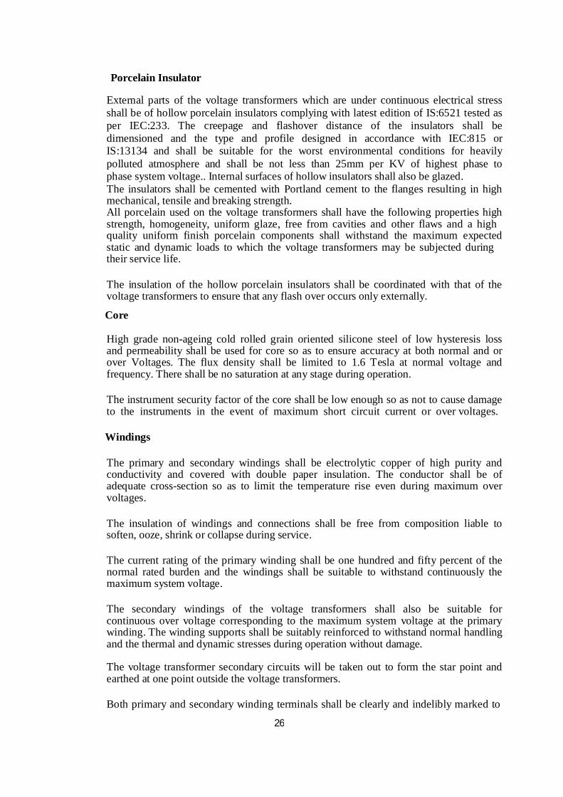
Porcelain Insulator
External parts of the voltage transformers which are under continuous electrical stress shall be of hollow porcelain insulators complying with latest edition of IS:6521 tested as per IEC:233. The creepage and flashover distance of the insulators shall be dimensioned and the type and profile designed in accordance with IEC:815 or IS:13134 and shall be suitable for the worst environmental conditions for heavily polluted atmosphere and shall be not less than 25mm per KV of highest phase to phase system voltage.. Internal surfaces of hollow insulators shall also be glazed. The insulators shall be cemented with Portland cement to the flanges resulting in high mechanical, tensile and breaking strength. All porcelain used on the voltage transformers shall have the following properties high strength, homogeneity, uniform glaze, free from cavities and other flaws and a high quality uniform finish porcelain components shall withstand the maximum expected static and dynamic loads to which the voltage transformers may be subjected during their service life.
The insulation of the hollow porcelain insulators shall be coordinated with that of the voltage transformers to ensure that any flash over occurs only externally.
Core
High grade non-ageing cold rolled grain oriented silicone steel of low hysteresis loss and permeability shall be used for core so as to ensure accuracy at both normal and or over Voltages. The flux density shall be limited to 1.6 Tesla at normal voltage and frequency. There shall be no saturation at any stage during operation.
The instrument security factor of the core shall be low enough so as not to cause damage to the instruments in the event of maximum short circuit current or over voltages.
Windings
The primary and secondary windings shall be electrolytic copper of high purity and conductivity and covered with double paper insulation. The conductor shall be of adequate cross-section so as to limit the temperature rise even during maximum over voltages.
The insulation of windings and connections shall be free from composition liable to soften, ooze, shrink or collapse during service.
The current rating of the primary winding shall be one hundred and fifty percent of the normal rated burden and the windings shall be suitable to withstand continuously the maximum system voltage.
The secondary windings of the voltage transformers shall also be suitable for continuous over voltage corresponding to the maximum system voltage at the primary winding. The winding supports shall be suitably reinforced to withstand normal handling and the thermal and dynamic stresses during operation without damage.
The voltage transformer secondary circuits will be taken out to form the star point and earthed at one point outside the voltage transformers.
Both primary and secondary winding terminals shall be clearly and indelibly marked to
27
show polarity in accordance with IEC:186. The connections required for different secondary windings in case of multi-winding voltage transformers shall be clearly indicated in terminal blocks and the wiring diagrams.
Tank
Both expansion chamber and tank of the voltage transformers shall be made of high quality steel and shall be hot dip galvanized and shall be able to withstand the stress occurring during transit and all thermal and mechanical stresses resulting from maximum short circuit current during operation.
Insulating Oil
The voltage transformers shall be supplied filled with new insulating oil. The oil shall conform to the requirements of latest issue of IEC:296 of IS:335. The quantity of insulating oil for first filling of the equipment and complete specification of oil proposed to be used shall be stated in the bid.
Hermetic Sealing
The voltage transformers shall be supplied filled with insulating oil and shall be hermetically sealed to prevent atmosphere coming in contact with oil, avoiding filtration and change of oil. Nitrogen or other inert gas shall be provided above the oil surface to permit expansion and contraction of oil. Provision shall be made for draining and re- filling the insulating oil.
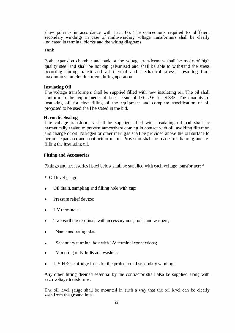
Fitting and Accessories
Fittings and accessories listed below shall be supplied with each voltage transformer: *
* Oil level gauge.
Oil drain, sampling and filling hole with cap;
Pressure relief device;
HV terminals;
Two earthing terminals with necessary nuts, bolts and washers;
Name and rating plate;
Secondary terminal box with LV terminal connections;
Mounting nuts, bolts and washers;
L.V HRC cartridge fuses for the protection of secondary winding;
Any other fitting deemed essential by the contractor shall also be supplied along with each voltage transformer:
The oil level gauge shall be mounted in such a way that the oil level can be clearly seen from the ground level.

28
The name and rating plate shall contain all the particulars as provided in IEC:186 and also the name of the employer and year of manufacture. They shall comply with the clause termed label in this specification.
SECONDARY TERMINAL BOX
A dust, vermin and weather proof terminal box shall be provided at the lower end of each voltage transformer for terminating the secondary windings. The box shall have a bolted removable cover plate complete with gaskets. The terminal box shall have cable gland plate and cable glands with shrouds suitable for entry of 4 core x2.5mm2 PVC insulated control cables as per IEC:227 or IS:1554. The terminal box enclosure shall have protection of class IP 55 as defined in IEC:529 or IS:13947 and shall be painted or galvanized in accordance with specification of Surface Treatment.
Terminal blocks
Terminal blocks of brass studs rated for 10 Amps continuous current, 650 Volt grade enclosed in moulded insulating materials shall be provided with adequate electrical clearance for terminating the secondary wiring and outgoing connections. The terminal blocks shall be suitable for termination of 2.5mm2 wires. The termination shall be made by crimping Jugs or bare wire with insulating sleeves at ends. All terminals must be marked with numbers and wire termination provided with numbered ferrules for identification.
Fuse protection
The secondary windings shall be protected by HRC cartridge fuses in fuse holder consisting of carriers and bases. The carriers and bases shall be of high grade flame retarding and non hygroscopic molded insulating materials with hard glass surface. Each fuse shall be identified with engraved plastic label.
Circuit diagram
A durable copy of the circuit wiring diagram shall be affixed to the inner side of the terminal box cover. Labels shall be provided inside the cover to describe the functions of various items of equipments.
TERMINATION
The equipment shall be supplied with HV electrical connection terminals of a size and rating appropriate for all the duties, including overload duty specified for the equipment. The terminals shall be of the bi-metallic type, suitable for connection of all aluminium alloy conductor (AAAC) or aluminium conductor steel reinforced (ACSR). In general connections using palm type solder less sockets shall be preferred. The proposed method of connections shall be stated in the offer and shall be subject to approval by the Purchaser. W here the terminals are of the clamp type, they shall be suitable for taking a range of conductors appropriate to the rating of the equipment.
All nuts, bolts, washers and spring washers required to complete the connection shall be supplied with the equipment.
29
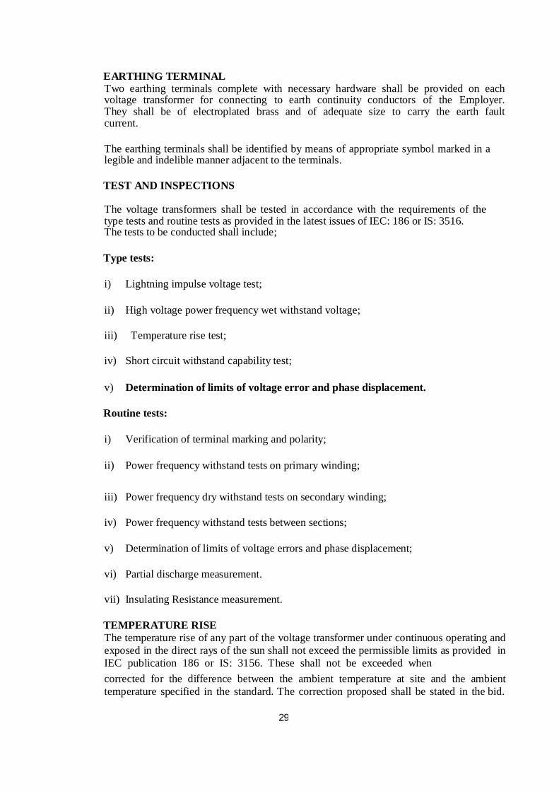
EARTHING TERMINAL Two earthing terminals complete with necessary hardware shall be provided on each voltage transformer for connecting to earth continuity conductors of the Employer. They shall be of electroplated brass and of adequate size to carry the earth fault current.
The earthing terminals shall be identified by means of appropriate symbol marked in a legible and indelible manner adjacent to the terminals.
TEST AND INSPECTIONS
The voltage transformers shall be tested in accordance with the requirements of the type tests and routine tests as provided in the latest issues of IEC: 186 or IS: 3516. The tests to be conducted shall include;
Type tests:
i) Lightning impulse voltage test;
ii) High voltage power frequency wet withstand voltage;
iii) Temperature rise test;
iv) Short circuit withstand capability test;
v) Determination of limits of voltage error and phase displacement. Routine tests:
i) Verification of terminal marking and polarity;
ii) Power frequency withstand tests on primary winding;
iii) Power frequency dry withstand tests on secondary winding;
iv) Power frequency withstand tests between sections;
v) Determination of limits of voltage errors and phase displacement;
vi) Partial discharge measurement.
vii) Insulating Resistance measurement. TEMPERATURE RISE
The temperature rise of any part of the voltage transformer under continuous operating and exposed in the direct rays of the sun shall not exceed the permissible limits as provided in IEC publication 186 or IS: 3156. These shall not be exceeded when corrected for the difference between the ambient temperature at site and the ambient temperature specified in the standard. The correction proposed shall be stated in the bid.
30
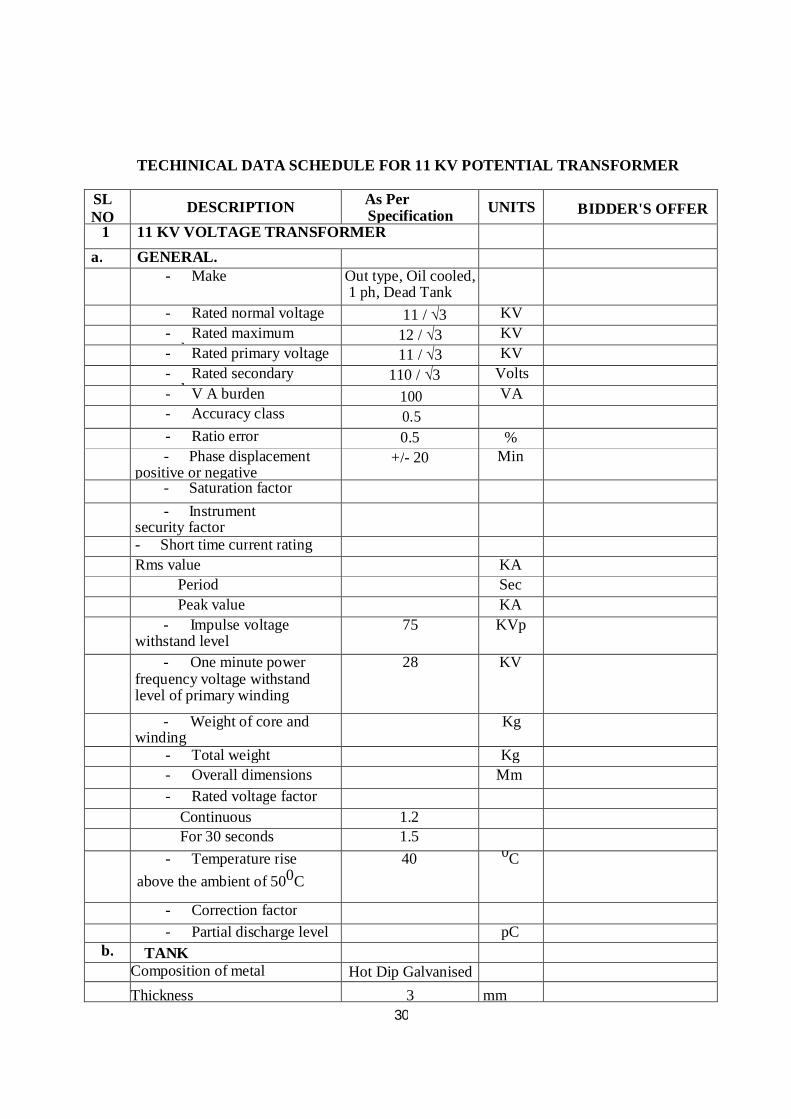
TECHINICAL DATA SCHEDULE FOR 11 KV POTENTIAL TRANSFORMER
SL NO
DESCRIPTION As Per
Specifications
UNITS
BIDDER'S OFFER
1 11 KV VOLTAGE TRANSFORMER a. GENERAL.
- Make Out type, Oil cooled, 1 ph, Dead Tank
- Rated normal voltage 11 / √3 KV - Rated maximum
voltage 12 / √3 KV
- Rated primary voltage 11 / √3 KV - Rated secondary
voltage 110 / √3 Volts
- V A burden 100 VA - Accuracy class 0.5 - Ratio error 0.5 % - Phase displacement
positive or negative +/- 20 Min
- Saturation factor - Instrument
security factor
- Short time current rating Rms value KA Period Sec Peak value KA - Impulse voltage
withstand level 75 KVp
- One minute power frequency voltage withstand level of primary winding
28 KV
- Weight of core and winding
Kg
- Total weight Kg - Overall dimensions Mm - Rated voltage factor Continuous 1.2 For 30 seconds 1.5 - Temperature rise
above the ambient of 500C 40 0C
- Correction factor - Partial discharge level pC
b. TANK Composition of metal Hot Dip Galvanised Thickness 3 mm

31
c. CORE - Material composition
(CRGO-M4 or better)
- Flux density at normal voltage and frequency
<1.2 Telsa
- Lamination thickness 0.27 mm d. WINDINGS
- Purity of copper used Electrolytic Percent - Type of insulation - Power frequency
withstand level
Secondary winding to earth
3 KV
Primary winding to earth 28 KV e. SECONDARY TERMINAL
BOX
- Degree of protection Yes/No - Vermin proof provision Yes/No - Weather proof
provision Yes/No
- Dust proof provision Yes/No - Thickness of metal used 3 mm - Overall dimensions mm - Mounting arrangement f. H V TERMINAL
- Material - Bi-metallic or not Yes/no - Dimensions, mm - Size and type of
conductor it can accommodate
100 Sq. mm
g. Drawing To be furnished by bidder
NB- Every PT should bear the marking of manufacturer’s name , Purchaser’s name Sl. No. , Rating etc.
Name & Signature of Bidder with seal

32