Embed Size (px)
Citation preview

E N V I R O N M E N T A L
M A N A G E M E N T P L A N
Groundwater Monitoring and Remedial Programme
Voyager II Quarry, The Lakes, Shire of Northam.
BGC (Quarries) Pty Ltd
PO Box 12157 Midland WA 6936
Revision 5 January 2014

Rev No. Date Author Approved by
1 March 2007 G.Bakesi, URS I.Le Provost, URS.
2 September 2011 R.Holmes, Holmes
Environmental
P.Yates, BGC Quarries.
3 August 2012 R.Holmes, Holmes
Environmental
P.Yates, BGC Quarries.
4 January 2014 Andre Stass,
Stass Environmental
P.Yates, BGC Quarries.
Contents
C:\Projects 2014\BGC\Groundwater and surface water management\Groundwater Management Plan 2014\Voyager II Groundwater MP R5 0 January 2014.docx
i
1 Element/Issue --------------------------------------------------------------------------------------------- 1-1
1.1 Introduction – Revision 4 1-1 1.2 Changes to the Management Plan 1-2 1.3 Legal Framework 1-2
2 Current Status -------------------------------------------------------------------------------------------- 2-1
2.1 The Project 2-1
3 Potential Impacts ---------------------------------------------------------------------------------------- 3-4
3.1 Potential Environmental Impacts of the Project 3-4 3.1.1 Local Hydrogeology 3-4 3.1.2 Water Table Configuration and Groundwater Flow 3-5 3.1.3 Groundwater Quality 3-11
4 Environmental Objectives----------------------------------------------------------------------------- 4-1
5 Criteria for Groundwater Monitoring and Management ------------------------------------- 5-1
5.1 General Considerations 5-1 5.2 Groundwater Level Criteria 5-1 5.3 Groundwater Quality Criteria 5-2
6 Groundwater Monitoring and Remedial Programme ----------------------------------------- 6-1
6.1 Implementation Strategy of Groundwater Management Plan 6-1
7 Contingencies -------------------------------------------------------------------------------------------- 7-1
8 Stakeholders ---------------------------------------------------------------------------------------------- 8-1
9 Ongoing Compliance Requirements --------------------------------------------------------------- 9-1
9.1 Auditing 9-1 9.2 Review, Revision and Reporting 9-1
10 References ----------------------------------------------------------------------------------------------- 10-1
11 Limitations ----------------------------------------------------------------------------------------------- 11-1

List of Tables, Figures, Plates & Appendices
C:\Projects 2014\BGC\Groundwater and surface water management\Groundwater Management Plan 2014\Voyager II Groundwater MP R5 0 January 2014.docx
ii
Tables
Table 1 Statutory & Policy Requirement for Groundwater Monitoring and Remedial Program .. 1.2
Table 2 Lithological Profile at the Voyager Quarry ...................................................................... 3-2
Table 3 Groundwater Infrastructure-Voyager Quarry ................................................................... .3-3
Table 4 Voyager II Groundwater Monitoring Program ................................................................. 6-1
Table 5 Groundwater Monitoring and Remediation Programme .................................................. 6-2
Table 6 Key Management Actions ................................................................................................ 9-2
Figures
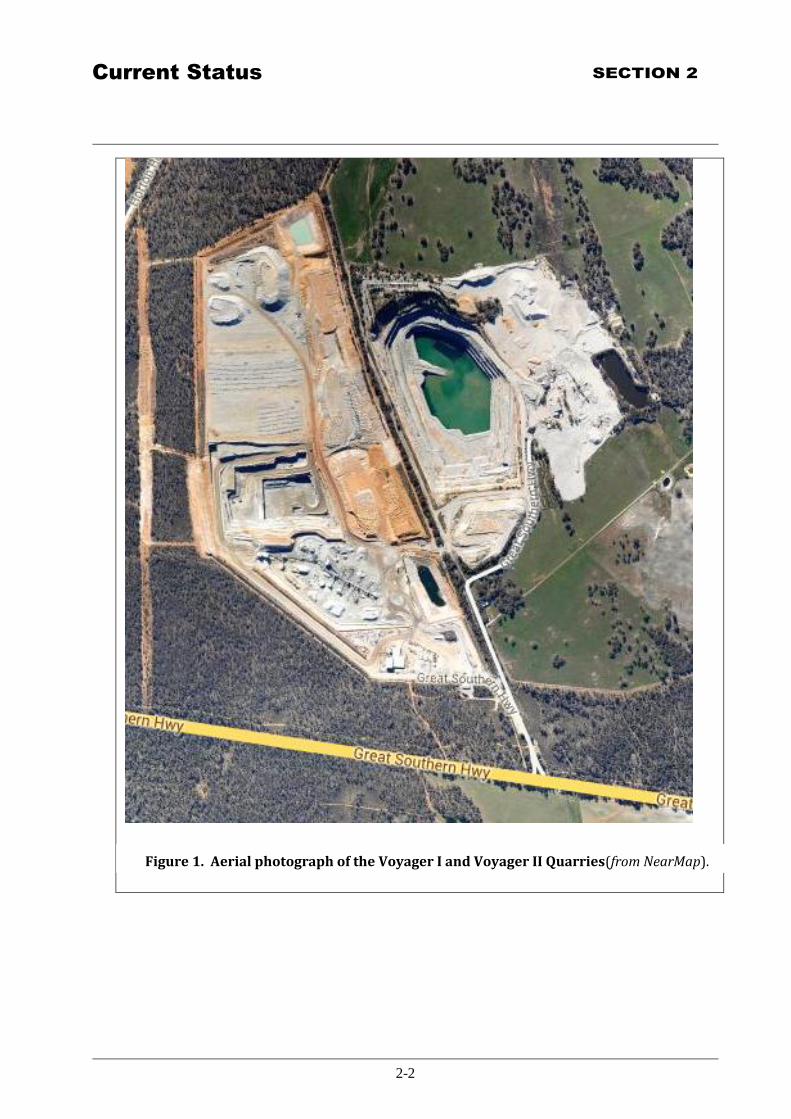
Figure 1 Aerial photograph showing Voyager II Quarry located to the immediate west of the now
decommissioned Voyager I Quarry ................................................................................... 2-2
Figure 2 Groundwater Investigations .............................................................................................. 2-3
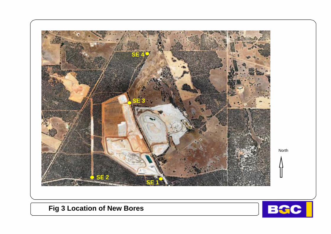
Figure 3 Location of New Bores ..................................................................................................... 2-4
Figure 4 Division of Areas within Voyager II Quarry ..................................................................... 2-5
Figure 5 SWL and bore locations December 2013 .......................................................................... 3-9
Figure 6 Regional Conceptual Cross Section from West to East .................................................... 3-10
Figure 7 Weekly Bore Sampling Data for BGC Bores .................................................................... 3-6

Element/Issue SECTION 1
1-1
1 Ele ment/Issue
1.1 Introduction – Revision 4
The proposal for the Voyager II Quarry was approved by the Minister for the Environment with the
signing of Ministerial Statement 706 on 16 December 2005. Relevant to this management plan is
Condition 13 reproduced in Section 1.3 below.
Further to a submission by BGC under Section 46 of the EP Act in October 2010– Statement 872 was
issued in August 2011 replacing Condition 706:M6.1 with a new condition that extends the use of the
tertiary crushers to 1900 hours on Saturdays.
Revision 1 of this Management Plan was prepared by URS (Australia) Pty Ltd on behalf of BGC
(Australia) Pty Ltd (BGC) in compliance with Ministerial Statement 706 Condition 13.1 (706:M13.1).
Revision 4 of this Management Plan has been prepared in compliance with 706:M13.6 that requires the
Management Plan be reviewed and updated on an annual basis. In April 2013 a further Ministerial
Statement No 934 was issued, which removed conditions 6 and 11 of the Statement 706.
Ministerial Statement 706 set conditions on the construction and operation of a new quarry (Voyager II)
that has now replaced the original Voyager Quarry - now nominated Voyager I. With the expiry of the
licence agreement between the BGC and the landowner AMB Holdings, the Operating Licence L5356
for crushing and screening at Voyager I was not renewed and was allowed to expire on 3 October 2010.
Quarrying operations were translocated to Voyager II Quarry located on adjacent land to the west that
was purchased by BGC. Voyager II was commissioned in October 2010 under Operating Licence L8415.
Revision 3 of this document was prepared subsequent to when BGC was denied access to lands
previously occupied by the operators of Voyager I Quarry. Subsequent to the expiry of the licence
agreement between BGC and the AMB Holdings, BGC was denied access to any of the lands previously
occupied by Voyager I Quarry operators in February 2011. Since that time, BGC has been unable to
conduct groundwater monitoring activities for those bores located on AMB Holdings land – these include
all bores prefixed MB as shown in Figures 2 and 4. The purpose of groundwater monitoring is to provide
remedial actions, as per Section 5.3 below, should the quality of groundwater deteriorate due to
drawdown caused by Voyager II quarrying operations. As a consequence of BGC being denied access to
AMB Holdings land, BGC can no longer be held responsible for any claims in regard to groundwater
quality within AMB Holdings land.
To compensate for the loss of monitoring bores, BGC have asked advice of Stass Environmental on
installation of new monitoring bores to provide a monitoring bore network that will generate good quality
data on the ground water regime, which is now focused on the Voyager II quarry as opposed to Voyager
I. This was done during October 2013, and 4 new monitoring bores were installed to complement the
existing bore monitoring network. All bores are now located on BGC land. ****
Voyager II Quarry management meetings all include a segment discussion on safety and environmental
issues under the guidance of the Health, Safety & Environment Officer. In these meetings, environmental
issues arising are discussed in terms of current management system adequacy. Decisions that may
improve environmental performance are implemented and are referred forward to the annual review
meeting for consideration of their effectiveness. Clearly, Management Plan Documents are subject to

Element/Issue SECTION 1
1-2
ongoing review, but not necessarily “updates” in every year of operation when the review does not find
adequate cause for an update of the document – in such circumstances the annual review outcome of
quarry operations would be that environmental issues are adequately managed under using the current
management plan (R4).
1.2 Changes to the Management Plan
The following are noted as changes from Revision 1 to Revision 2 of this Management Plan
Voyager I Quarry was decommissioned in October 2010 and ownership of the land occupied by
both the void and the operational areas are in the control of the landowner.
Voyager II Quarry was commissioned on 24th September 2010 and is now in full operation.
o Areas 1 and 2 have been excavated to a level platform for the quarry operational area.
o Areas 3 and 4 have been cleared, overburden has been removed and these areas are now the
source of quarry material for processing through crushing and screening.
o Areas 5 and 6 have been cleared of vegetation in preparation for future overburden removal.
Bores designated for weekly monitoring in Revision 1 are now monitored on a bi-annual basis
(see Section 6.1).
Private bores nominated for annual monitoring are now monitored bi-annually so as to
approximate summer minimum and winter maximum groundwater levels.
Bores BGC1 and BGC2 listed in Revision 1 were destroyed by the development of mining areas
for Voyager II Quarry.
Monitoring of Bores prefixed MB has not been monitored since February 2011 after BGC was
denied access to AMB Holdings‟ land.
Four new monitoring bores have now been installed to complement the existing ground water
monitoring network, as per Hydrogeological report of October 2013, provided by Stass
Environmental (see Figure 3).
1.3 Legal Framework
The use of groundwater in WA is controlled by the Rights in Water and Irrigation Act 1914 and applies to
the management of water resources. Due to low bore yields and generally poor groundwater quality, the
area containing the Voyager I and Voyager II quarries is not within a proclaimed groundwater area under
the Rights in Water and Irrigation Act 1914. There is no formal requirement for a Groundwater
Management Plan for groundwater abstraction and use within this area.
The quality of groundwater should be maintained or improved to ensure that existing and potential uses,
including ecosystem maintenance are protected, consistent with the Australian and New Zealand Water
Quality Guidelines (ANZECC, 2000). Legislation and guidelines that apply to this Groundwater
Monitoring and Remedial Programme are outlined in Table 1.

Element/Issue SECTION 1
1-3
Table 1: Statutory and Policy Requirements for Groundwater Monitoring and
Remedial Programme
Agency Statute/Guideline Applicability
OEPA and
Department of
Environment
Regulation
(DER)
Environmental Protection Act 1986 Ministerial Statement 934 issued under
Part IV of the EP Act
Guideline: Preparing
Environmental Management Plans
This document has been prepared in
compliance with the Guidelines
Department of
Water (DoW)
Rights in Water and Irrigation Act
1914
Management of water resources
National Health
and Medical
Council (Australia)
Australian and New Zealand
Guidelines for Fresh and Marine
Water Quality (2004)
Use of Groundwater
Revision 1 of the Ground Water Monitoring and Remedial Programme was prepared in compliance with
Ministerial Statement 706, Condition 13 which is reproduced below.
Further to a submission by BGC under Section 46 of the EP Act in October 2010– Statement 872 was
issued in August 2011 and updated again by Statement 934 of April 2013, deleting conditions 6,11 & 17.
Prior to clearing of vegetation or excavation of soil or rock, whichever is the sooner, the proponent shall
prepare a Groundwater and Surface Water1 Monitoring and Remedial Programme, to the requirements
of the Minister for the Environment.
The objective of this Programme is to monitor groundwater levels adjacent to the quarry, and
the quantity and quality of surface water leaving the site to ensure that the operations are not
resulting in a reduction of water levels of existing bores of neighbours or any significant decline
in the quality of waters downstream of the quarry, and to define management actions and
contingency measures to be implemented in the event of adverse impacts on the water levels of
bores or salinity in downstream waters caused by quarry and associated operations.
1 The Surface Water Monitoring and Remedial Programme is presented in a separate document

Element/Issue SECTION 1
1-4
This Programme shall:
1. be designed and implemented in a manner which is capable of identifying any adverse impacts
from quarrying and associated activities on surface and groundwater in the vicinity of the
proposal;
2. incorporate separate monitoring for surface water and groundwater;
3. identify key monitoring locations;
4. identify water quality criteria and limits to be met;
5. identify baseline levels for groundwater supplies on adjacent properties;
6. include a monitoring schedule;
7. include a reporting schedule; and
8. define management actions and contingency measures to be implemented in the event of
adverse impacts on the water levels of bores or water quality in downstream waters caused by
quarry and associated operations.
13-2 The proponent shall implement the Groundwater and Surface Water Monitoring and Remedial
Programme required by condition 13-1 and any subsequent updates as required by condition 13-6.
13-3 The proponent shall ensure that water quality criteria and limits identified within the Groundwater
and Surface Water Monitoring and Remedial Programme are not exceeded.
13-4 The proponent shall report any exceedance of the limits identified within the Groundwater and
Surface Water Monitoring and Remedial Programme to the Department of Environment within 24
hours of being observed.
13-5 The proponent shall provide a report to the Department of Environment relating to the
exceedances referred to in condition 13-4 within seven days of being recorded, identifying the
sources of the exceedance within the proposal area and indicating remedial action undertaken to
prevent further such exceedances.
13-6 The proponent shall review and update the Groundwater and Surface Water Monitoring and
Remedial Programme required by condition 13-1 annually.
13-7 The proponent shall make the Groundwater and Surface Water Monitoring and Remedial
Programme required by condition 13-1 publicly available.

Current Status SECTION 2
2-1
2 Current Status
2.1 The Project
The Voyager II Quarry is on the north side of the Great Southern Highway, about 3.5 km east of the
intersection of the Great Eastern and Southern Highways (Figure 1), on Lot 14 Horton Road, The Lakes
(Avon Location 1881), Shire of Northam. Figure 1 shows the new Voyager II quarry located to the west
of Voyager I Quarry.
Development of the Voyager II Quarry will ultimately entail excavation of up to 2 million tonnes of
gravel and approximately 12 million tonnes of clay from the quarry footprint. These excavations will
allow approximately 60 million tonnes of granite to be quarried from the site over an estimated 50-year
period. The first areas that were quarried are designated Area 1 and Area 2 as shown on Figure 4. In
these areas a bench was created at 30m below the original ground level for locating the processing of
quarry product. Areas 3 and 4 are now the source of ROM material that is fed to the primary crusher.
Areas 5 and 6 have been cleared of vegetation and will be subject to overburden removal for quarrying at
a future time not yet determined.
Quarrying has now proceeded into the granite bedrock, and groundwater seeps from fissures and cracks
flow to the lowest point of the quarry which is the quarry sump; thus groundwater flowing into the quarry
sump result in the lowering of the water table in the immediate vicinity of the quarry. Groundwater
collected in the sump is pumped for storage in a surface dam and is available for dust suppression and
processing water.
Note that the operator of Voyager II Quarry does not abstract groundwater from any of the bores listed in
this document – these are used only for monitoring groundwater levels. All non-potable water
requirements of the quarry are met by rainwater collection and seepage into the quarry void.
A site-specific programme of investigation was carried out prior to the development of Voyager I and
included the following tasks:
Census of private groundwater wells and soaks and survey of elevations.
Construction of eleven monitoring bores in vicinity of quarry (refer Figure 2).
Monitoring of groundwater levels over a 12 month period.
Interpretation of historical air-photographs.
Measurement of water-balances of Voyager I Quarry Sump and Quarry Dam.
Current Status SECTION 2
2-2
Figure 1. Aerial photograph of the Voyager I and Voyager II Quarries(from NearMap).

North
Fig 2 Ground water Investigations
North
SE 3
SE 2
SE 4
SE 1
Fig 3 Location of New Bores

Current Status SECTION 2
2-5
Figure 4: Division of development stages within Voyager II Quarry.
Area 4 Area 3
Area 2Area 1
Area 5
Area 6
BGC VOYAGER QUARRY - THE LAKES, NORTHAM
Division of Areas
Herring Storer Acoustics
Length scale00 50 100 200 300 400
m
Voyager I Quarry

Potential Impacts SECTION 3
3-4
3 Potential Impacts
3.1 Potential Environmental Impacts of the Project
Public submissions in response to the PER (URS 2004) raised a number of groundwater issues which
were considered to require further evaluation. The main issues of concern were as follows:
Drawdown of the water table, depleting local aquifers and adversely affecting private water-
supplies.
Localised recharge to groundwater from quarry operations, causing local rise of the water table
downstream and in turn salinisation of surface soils.
Inadequate characterisation of groundwater inflows to the Voyager I quarry operations.
Although these issues largely referred to Voyager I Quarry, similar problems were envisaged with the
Voyager II Quarry. However, groundwater studies (see Section 3.1.3 below) in support of the PER
showed that these concerns were unfounded. Further ground water studies in 2013, based on the data
from installation of the new bores on BGC property confirmed these conclusions.
3.1.1 Local Hydrogeology
The Voyager II quarry site occurs in the Darling Scarp Province of Western Australia. The province is
characterised by streams that deeply incise the laterite profile and underlying granite bedrock. There are a
number of structural lineaments2 visible in the aerial photographs which reflect cross-cutting dolerite
dykes or regional fracture zones (URS, 2004). The most prominent set is west-northwest in orientation;
in the Voyager I quarry this set corresponds with sub-vertical dolerite dykes. The margins of the dykes
are fractured, except for the northern margin of the dyke in the north wall of the quarry, which is
annealed. Individual fracture zones close with depth and are unlikely to be open below 50 to 60 m from
surface. The complete weathered profile is indicated in Table 2.
The Voyager I and II Quarries occur in the upper-most reaches of the Wooroloo Brook Catchment,
immediately adjacent to the catchment divide lying immediately to the south of Voyager I (Figure 2).
Concerns were that the development of Voyager quarries could intersect steeply dipping fractures
containing minor amounts of groundwater which would drain to the sump at the base of the quarry. The
concerns expressed in public submissions were that this may reduce groundwater levels near the Voyager
I quarry (URS, 2004).
In fact, the thickness of the individual lithologies is highly variable, and any or all of the upper lithologies
may be very thin or absent at a particular site. The general area in the vicinity of the Voyager Quarries is
underlain by granite bedrock, weathered to depths ranging from nil to over 30 m.
2 These are fault lines or fractures in the granite structure due to crustal movements over geological time spans.
Potential Impacts SECTION 3
3-5
Table 2: Lithological Profile at the Voyager Quarry
Depth (m) Lithology
0 – 2 Lateritic gravel and clay
3 – 20 Kaolin clay and quartz sand (clayey sand and sandy clay)
20 – 25 Weathered and decomposed granite
25 – 30 Fractured granite, fresh to slightly weathered
>30 Fresh granite bedrock, hard, rare fractures
The most transmissive aquifer zones are the weathered profile just above fresh bedrock, and the upper
few metres of fractured bedrock. Regional structural lineaments and the margins of associated dolerite
dykes may be particularly fractured. The fresh bedrock, where unfractured, is essentially impermeable.
Small amounts of potable groundwater are available from bores and wells that intersect fractures within
the granite bedrock, but generally yield less than 15 kL/day. Those bores and wells sited in valleys or on
foot slopes may give larger supplies, but the groundwater salinity is generally higher than in surrounding
areas.
3.1.2 Water Table Configuration and Groundwater Flow
The regional water table and groundwater flow directions are shown in Figure 5, compiled by contouring
all surveyed groundwater levels in bores, wells, soaks and dams in December 2013. The water table
contours were interpolated between data points.
When Voyager I was in operation the water table showed a steep depression restricted to the immediate
vicinity of the quarry, reflecting seepage into the pit and the very low transmissivity of the fresh bedrock.
There was no evidence of any drawdown effect on the nearest private bores, over 1 km to the west. The
groundwater levels in these bores in June 2013 were similar to the original groundwater level at the
Voyager I quarry site recorded in 2004.
Similarly there are no indications of a recharge mound down-gradient from Voyager I quarry. The
upward hydraulic head in the valley containing the Voyager I quarry, and the already shallow water table,
would prevent the formation of such a mound.
Groundwater levels in the monitoring bores constructed in 2004 continue to show an upward hydraulic
head from the base of the profile to the water table, except at the most northerly site, MB3. Upward head,
indicated by the existence of artesian bores reflected the greater transmissivity of the base of the
weathered profile, transmitting throughflow by recharge in the uppermost part of the catchment. This
upward head, coupled with the shallow water table, prevents significant recharge along the floor of the
valley (URS, 2004).
Table 3 presents groundwater infrastructure, monitoring sites, and surrounding private bore locations,
shown on Figure 5.

Potential Impacts SECTION 3
3-6
Table 3. Groundwater Infrastructure – Voyager II Quarry
Source Property Coordinates Elevation
(mAHD) Easting Northing
BGC Bores & Dams
VQ1S Lot 14 Horton Rd 438325 6474393 350.25
VQ1D Lot 14 Horton Rd 438324 6474395 350.28
VQ2S Lot 14 Horton Rd 438478 6474770 326.28
VQ2D Lot 14 Horton Rd 438478 6474773 326.28
SE 1 Lot 14 Horton Rd 439290 6473259 338.14
SE 2 Lot 14 Horton Rd 438165 6473253 338.95
SE 3 Lot 14 Horton Rd 438760 6474706 301.51
SE 4 Lot 14 Horton Rd 439011 6474706 289.90
Local Resident Bores and Dams
Dam Lot 5 Horton Rd 437481 6474266 305.83
Solar Bore Lot 5 Horton Rd 437544 6474271 310.44
Disused Bore Lot 5 Horton Rd 437745 6474101 325.28
House Bore Lot 5 Horton Rd 437805 6474271 328.05
Dam West 598 Wariin Road 440440 6474907 302
Dam East 598 Wariin Road 440607 6474665 301
PB010 (2.5) 598 Wariin Road 440405 6475532 285.65
PB010 (7.0) 598 Wariin Road 440400 6475530 285.88
Dam next to PB09 598 Wariin Road 440367 6475919 284
PB009 (5.5) 598 Wariin Road 440308 6475956 280.4
Dam next to PB10 598 Wariin Road 440426 6475612 288
Bore 1.5 Lot 13 Horton Rd 439217 6475919 289
Bore 3 Lot 13 Horton Rd 439217 6475919 289
Dam Bore 1.5 Lot 13 Horton Rd 439266 6475913 288
Dam Bore 3 Lot 13 Horton Rd 439266 6475913 288
New North Dam Lot 13 Horton Rd 440484 6474951 North Dam Lot 13 Horton Rd 439218 6475780 276.49
South Dam Lot 13 Horton Rd 439037 6476216 278.68
New Bore NE Lot 13 Horton Rd 439465 6475993 293
Bore Lot 2 Cable St 436719 6474446 274
Large Dam Lot 2 Cable St 436707 6474423 274.67
Bore Lot 1 Cable St 436744 6474074 284
Dam Lot 1 Cable St 436708 6474063 Bore Lot 3 Cable St 437105 6473987 289.96
Road Dam Lot 3 Cable St 436805 6474024 281.36
Dam Lot 3 Cable St 437026 6474109 281.32
All the above are monitored twice a year, if access is available and/or bores are unobstructed.

Potential Impacts SECTION 3
3-7
Estimate of Potential Drawdown Impacts – from Revision 1
Groundwater studies (URS 2004) showed no evidence that Voyager I Quarry had affected the
groundwater levels in any private bores or other water-sources in the vicinity. This continues to be the
case in December 2013, inclusive of observations from new bores and recorded water elevations in
domestic bores. The quarry area and the private bores are separated by a groundwater divide
(approximately 330 m RL groundwater level to the west of the quarry (Figure 5). A conceptual west to
east cross-section (Figure 6) shows the groundwater divide beneath BGC2. Further, Voyager II is to the
east of the groundwater divide and most of the private bores are situated to the west of the groundwater
divide (see blue arrows, Figure 5).
Conservative estimate of the radius of effect of drawdown from the quarry using the Theis non-
equilibrium formula is:
S
Ttr
25.2
where: r = radius of drawdown influence (m)
T = transmissivity (m2/day)
t = time (days)
S = storativity (dimensionless)
Adopting 200 days as the likely maximum time between recharge periods, estimates of drawdown
influence can be made for the bulk profile, and the „worst case‟ of highest transmissivity and low
storativity along a major fracture zone, as follows:
Bulk Profile (transmissivity 0.1 m2/day, storativity 0.005)
mxx
r 95005.0
2001.025.2
Major Fracture Zone (transmissivity 10 m2/day, storativity 0.005)
mx
r 950005.0
2001025.2
Thus, in general, drawdown effects were predicted to be limited to within 100 m of the Voyager II quarry,
except along any major fracture zones which intersect the void, along which drawdown could extend up
to about 1 km away.
The minimum separation distance between the quarry and private bores is 1200 m therefore no drawdown
is estimated to be likely that would affect private bores as a result of Voyager II operations.

Potential Impacts SECTION 3
3-8
Another way of estimating drawdown impacts is to simulate the net groundwater abstraction from the
quarry under a range of effective hydraulic parameters (transmissivity and storativity). Using a range for
transmissivity, T, between 0.05 and 10 m2/day; and storativity, S, between 0.001 and 0.09, and using the
net groundwater abstraction associated with the quarry (90 kL/day) 98% of the simulated scenarios
predict <0.1 m draw downs at 1,000 m distance. These results confirm the previous estimates and
conclusions that bores beyond 1,000m distance from the quarry would not be affected by drawdown.
There was essentially no groundwater intersected by the new bore SE 2, drilled west of Voyager II quarry
and consequently the cone of drawdown was not definable in this area. Based on these drilling results,
the amount of additional groundwater flow to the quarry, due to Voyager II is estimated to be low and
limited to discharges from steep fractures in fresh granite and direct rainfall recharge to the saprolite zone.
In conclusion, the available data and interpretations indicate that drawdown impacts due to quarrying
operation is limited to distances up to about 100 m from the pit edge.
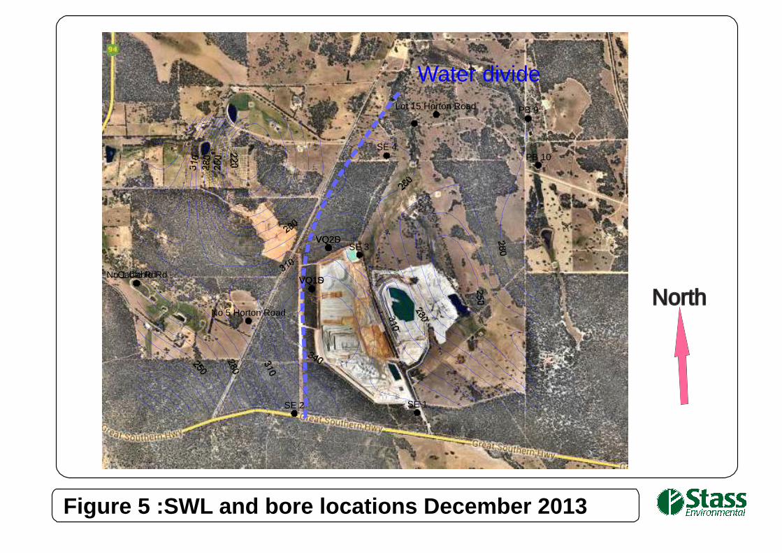
Figure 5 :SWL and bore locations December 2013
North
Water divide
VQ1SVQ1D
VQ2SVQ2D
SE 1SE 2
SE 3
SE 4
No 5 Horton Road
PB 9
PB 10
Lot 15 Horton Road
Cable RdNo 1 Cable Rd

Voyager I Quarry
Voyager II Quarry
Fresh GraniteWater Table
0 250 500 750 1000m
Scale
WEST EASTNo 5 Horton Rd
No 7 Cable Street
Fig 6 - Schematic cross section through the study region

Potential Impacts SECTION 3
3-11
3.1.3 Groundwater Quality
Characterisation studies of the groundwater environs of Voyager I were conducted prior to the
development of the Voyager II quarry. The discussion of results arising from these studies is presented
below.
Groundwater samples were taken from all monitoring bores and from private bores between May and
June 2004. The salinity of groundwater in the upper parts of the Wooroloo Brook Catchment varies from
less than 1,000 to more than 7,000 mg/L Total Dissolved Solids (TDS). There is an increase in salinity
from west to east across the catchment (URS, 2004).
The groundwater, whether from shallow or deep parts of the profile, is generally brackish to saline, except
SE 1, which is fresh (less than 1,000 mg/L TDS). SE 1 may have intercepted perched groundwater or had
a low salinity because of enhanced local winter rainfall recharge coinciding with a topographical high.
SE 1 is on the eastern flank of the uncleared part of Horton Hill, and may also reflect the occurrence of
local rainfall recharge.
The salinity of the shallow groundwater is higher or similar to the deeper groundwater at each of the
paired monitor bore sites, with MB5 being an exception. This salinity distribution is probably due to
solution of salt in the upper part of the soil profile, as the deeper groundwater rises through the weathered
profile under upward hydraulic head.
The groundwater in the cleared agricultural areas in all private and monitoring bores is almost exclusively
acidic, ranging in pH from 3.5 to 5.7. The shallow groundwater is more acidic than the deeper
groundwater, perhaps supporting the interpretations of longer flow paths, mobilisation of salts, and
distribution of salts in the shallow water table profile.
In past monitoring events, groundwater in the deeper monitoring bore sites MB3D and MB5D has been
almost neutral in pH. In contrast the surface water, including the creeks downstream from the Voyager I
quarry, has been generally neutral to alkaline. Where the groundwater discharges to the watercourses, the
release of dissolved gases, such as carbon dioxide and hydrogen sulphide, may contribute to an increase
in pH, or the increased alkalinity may be attributed to surface runoff.
There appears to be a general increasing of EC values down gradient, although there are exceptions to this
trend, probably because of local variations in recharge and lengths of flow path. The EC values in the
valley north of the Voyager II Quarry are generally higher than elsewhere, probably because of the
greater area of clearing in the upper part of this valley, shallow water table setting, increased effects of
salinisation and increased lengths of flow paths from recharge areas.
There have been no indications of increased salinity due to the operation of the Voyager I Quarry and
there is no evidence of the Voyager II Quarry contributing salinity in the downstream catchments. The
noted occurrence of salt-affected soils has been caused by groundwater levels rising as a consequence of
clearing. The occurrence of salt-affected soils is evident on air photography taken in 1989 before the
Voyager I quarry was operational (URS, 2004).

Potential Impacts SECTION 3
3-12
Previous investigations focused on the relative distribution of salt in the weathered profile. The results
show generally higher concentrations in the top 10 m, and increasing concentration at depths beyond
25 m. The upper zone of salinity is interpreted to represent salt accumulated below the root zones of
native vegetation before the land was cleared. The deeper salinity corresponds with the occurrence of
saline groundwater above fresh bedrock.

Environmental Objectives SECTION 4
4-1
4 Environmenta l Objectives
The operational objectives of the Groundwater Monitoring and Remedial Programme are to:
Allow dry quarrying conditions.
To provide sufficient water for mining and processing activities.
To protect the groundwater available to other users, including the environment.
The Groundwater Monitoring and Remedial Programme is to ensure that the quarry operations do not
cause a reduction in groundwater levels in existing private bores on neighbouring properties or significant
decline in the quality of waters downstream of the quarries. The Groundwater Monitoring and Remedial
Programme defines management actions and contingency measures to be implemented in the event of
adverse groundwater impacts caused by quarry and associated operations.
The Groundwater Monitoring and Remediation Programme as required by the Ministerial Statement 706:
M13.1 shall:
1. Be designed and implemented in a manner which is capable of identifying any adverse impacts
from quarrying and associated activities on surface and groundwater in the vicinity of the
proposal.
2. Incorporate separate monitoring for surface water and groundwater.
3. Identify key monitoring locations.
4. Identify groundwater quality criteria and limits to be met.
5. Identify baseline levels for groundwater supplies on adjacent properties.
6. Include a monitoring schedule.
7. Include a reporting schedule.
8. Define management actions and contingency measures to be implemented in the event of
adverse impacts on the groundwater levels in bores or groundwater quality in downstream
environments caused by quarry and associated operations.
Section 5 addresses groundwater levels and quality criteria (Items 4 and 5 above). The remaining items
are addressed in Section 6. Management actions and contingencies are addressed in Section 7.

Criteria for Groundwater Monitoring
and Management
SECTION 5
5-1
5 Criteria for Groundwater Monitoring and Manageme nt
5.1 General Considerations
The criteria of a management plan are generally used to track progress in achieving objectives and targets.
These indicators should be specific, objective, achievable, relevant and time-framed, and therefore
verifiable and reproducible.
Possible indicators and criteria may include ANZECC water quality guidelines, site-specific criteria,
regulatory standards (e.g. Noise Regulations) and Australian Standards. Measurable performance criteria
are crucial elements of a management plan, allowing the proponent and regulatory bodies, to confirm the
effectiveness of management strategies and for proponents to demonstrate compliance with
environmental regulation. They are also an important tool for monitoring continuous improvement.
The main criteria of this management plan are the observation of the development of the groundwater
levels including the response of groundwater levels due to seepage into the quarry and the monitoring of
the development of groundwater salinity levels.
The use of groundwater is controlled by the Rights in Water and Irrigation Act 1914. This Act also
applies to the management of water resources. The quality of groundwater should be maintained or
improved to ensure that existing and potential uses, including ecosystem maintenance are protected,
consistent with the Australian and New Zealand Water Quality Guidelines (ANZECC, 2004).
5.2 Groundwater Level Criteria
The main groundwater issues addressed in the response to the PER (2004) were as follows:
Drawdown of the water table by the Voyager I quarry, depleting local aquifers and adversely
affecting private water-supplies.
Localised recharge to groundwater caused by quarry operations, causing local rise of the
water table and in turn salinisation of surface soils.
The monitoring bores incorporate piezometer pairs, VQ1 and VQ2, one screen in the shallow water table
zone (VQ1S and VQ2S) and the other in the fractured bedrock (VQ1D and VQ2D). These monitoring
bores were installed adjacent to the lineaments along the boundary of the area of Voyager II (Figure 2) of
the quarry and closest to private bores. Hence these bores lend themselves to be used as baseline
groundwater level observation sites.
Four new bores were proposed in 2013, to complement the existing bore monitoring network (SE 1 to SE
4). SE 3 was located in one of the lineaments mentioned above, while the rest of the bores were located to
observe any ground water changes that could be attributed to operation of the Voyager II quarry.
The baseline level for these bores is 5 m below the groundwater level after installation. If the groundwater
levels decrease further, the groundwater levels at the private bores should be monitored as well. As
required by Condition 706:M13.1, in the unlikely event that there is a reduction of water levels in bores of
neighbours as consequence of drawdown caused by Voyager II Quarry, then BGC will liaise with the
affected parties to formulate an equitable solution.

Criteria for Groundwater Monitoring
and Management
SECTION 5
5-2
Groundwater mounding is unlikely down-gradient of the Voyager II Quarry because of the upward
hydraulic head and already shallow water table. Groundwater levels, previously monitored at sites
MB2S, MB5S, MB6S were the best positioned of existing bores to capture any down-gradient mounding.
A criterion, that mean groundwater level mounding of MB2S, MB5S, and MB6S does not exceed 0.5 m
above seasonal range due to quarry operations is recommended, and had been maintained between 2004
and 2013.
5.3 Groundwater Quality Criteria
Since the groundwater in the catchment is saline to brackish, and TDS concentrations of over 3500 mg/l
have been analysed in some private bores to the west, the most appropriate water quality criteria is to
maintain or improve groundwater quality baseline down-gradient of the Voyager II Quarry operation. If
the monitoring programme shows that groundwater quality is significantly affected due to quarry
operations, based on Electrical Conductivity (EC) of groundwater at down-gradient sites SE 1 and SE 3,
and the survey of private bores indicate significant EC increases, as per Condition 706:M13.1, BGC will
liaise with the affected parties.

Groundwater Monitoring and Remedial
Programme
SECTION 6
6-1
6 Groundwater Monitoring and Re medial Programme
6.1 Implementation Strategy of Groundwater Management Plan
Revision 1 of this Management Plan proposed that groundwater levels be taken on weekly schedule for
“monitoring” bores and annually for all other bores listed in Table 3 that are not owned by BGC.
Weekly monitoring of groundwater bores to date has shown that there are insignificant changes in
measured parameters from one week to the next; this is evident from a plot of bore groundwater levels
monitored on a weekly basis since February 2007 in data submitted to the OEPA (see Figure 7). Minimal
changes are evident when plotting weekly monitoring data, where changes of interest may only become
noticeable on monthly or at bi-annual intervals.
Table 4 presents the recommended groundwater monitoring programme and criteria not to be exceeded.
The bores listed under “criteria” are the most appropriate because of their location and proximity to
private bores. The rest of the monitoring serve as supporting data. Samples will be collected in
agreement with
Australian/New Zealand Standards 5667.11: Water quality – Sampling, Part 11: Guidance on
sampling of groundwaters.

Fig 7 - Weekly bore data plotted for bores VQ1 S & D and VQ2 S & D
Ground LevelLevel belo
w G
round S
urf
ace
-40
0
16-Feb-07 16-Feb-08 16-Feb-09 16-Feb-10 16-Feb-11 16-Feb-12
Date
VQ1 S VQ1 D VQ2 S VQ2 D

Groundwater Monitoring and Remedial
Programme
SECTION 6
6-1
Table 4: Voyager II Groundwater Monitoring Program
Measurement Sample Location Frequency Criteria
Drawdown
Groundwater level
All monitoring bores as per
Table 3.
Bi-annually monitoring of
BGC and private bores
(Table 3) to gauge summer
minimum and winter
maximum.
New bore is to be
installed for this purpose
on Horton Rd close to
dust sampling station.
Groundwater Quality-EC Monitoring bores
All BGC Bores
Six-monthly
Water Quality
EC, TDS, TSS
All private Bores listed in
Table 3
Bi - annually

Groundwater Monitoring and Remedial
Programme
SECTION 6
6-2
The overall responsibility for implementing the EMP will be the Quarry Manager. Table 5 also lists the
proposed full implementation plan. The implementation of the Groundwater Monitoring and Remedial
Plan should be consistent with the Water Quality Protection Guideline (Water and Rivers Commission
2000).
Table 5: Groundwater Monitoring and Remediation Programme
Management Tools Responsibility for
Implementation and
Management
Action Monitoring and Internal
Audits
Construction and Operational Phases of Voyager II
Complaints Register. Quarry Manager Record all complaints
regarding groundwater
received directly from residents
or via councils. Details to be
recorded are:
Complainant;
Address of complainant;
Time of complaint; and
Nature of complaint.
Audit implementation of the
complaints response
procedure.
Groundwater Monitoring
Programme
Quarry General Manager,
Quarry Environmental
Manager
Continue groundwater
monitoring programme in
accordance with licence
conditions.
As indicated in this
document.
Contingencies SECTION 7
7-1
7 Contingencies
If the monitoring programme shows significant draw-downs, mounding, or salinity increase as specified
in Table 4, the Quarry Manager is to inform private bore owners who may be affected and OEPA within
24 hours of the excedance being known and implement a survey of groundwater levels and/or EC.
Depending on the criteria exceeded different contingencies are available for the Quarry Manager.
Possible contingencies include, but are not limited to:
Supply privately owned bore owners with adequate water of similar or better quality within seven
days of the problem being drawn to the attention of the quarry operator and investigated, if the
impact is shown to be the result of the quarry operation.
Further investigate/identify the cause.

Stakeholders SECTION 8
8-1
8 Stake holders
The following has been identified as stakeholders:
A Community Liaison Group is being established in accordance with the requirements of Condition
706:M19. The Liaison Group will include representation by Local Government, local residents and
government agencies including the OEPA.

Ongoing Compliance Requirements SECTION 9
9-1
9 Ongo ing Compliance Requirements
9.1 Auditing
The Quarry Manager and Environmental Officer will be required to ensure that all management actions as
per Section 6 and 7 of this document are carried out.
The OEPA Environmental Audit Branch has a policy of conducting audits from time to time to verify
compliance by proponents with Ministerial Conditions.
9.2 Review, Revision and Reporting
Review of this Management Plan to be performed on an annual basis and the document revised as
appropriate.
As proposed by the Ministerial Statement, the proponent shall report any excedance of the limits
identified within the Ground and Surface Water Monitoring and Remedial Programme to the OEPA
within 24 hours of becoming aware of the excedance.
The proponent shall provide a report to the OEPA relating to the exceedances within seven days of the
submission of the report, identifying the potential sources of the excedance within the proposal area and
indicating remedial actions undertaken (Table 6).

Ongoing Compliance Requirements SECTION 9
C:\Projects 2014\BGC\Groundwater and surface water management\Groundwater Management Plan 2014\Voyager II Groundwater MP R5 0 January 2014.docx
9-2
Table 6: Key Management Actions
Reference Issue Target/Objective OEPA Reporting/Evidence Management Action When Responsibility
GW1 Monitoring
Bores VQ1S,
VQ1D, VQ2S,
VQ2D, SE 1, SE
2, SE 3, SE 4.
completed completed completed Completed Quarry
Manager
GW2 Monitor
groundwater
level in bores bi-
annually
Less than 5 m below the
baseline for new bore to
be installed on Horton Rd.
Analysed monitoring data
submitted to OEPA annually.
Notification letter sent to
OEPA within 24 hours of
becoming aware of
excedance.
Inform Owners of Private
Bores
Survey of groundwater levels
in all bores.
Alternative groundwater
supply for owners of private
bores.
Within 7
days of
notification.
Quarry
Manager

References SECTION 10
10-1
10 References
ANZECC (2000): Australian and New Zealand Water Quality Guidelines, ISBN 09578245 0 5
Department of Environment (2006). Compliance Monitoring and Reporting Guidelines for Proponents:
Preparing environmental management plans. Perth, WA.
Herring Storer Acoustics (2002). Noise & Vibration Impact Assessment, BGC Australia Pty Ltd. Re-
location of the Voyager Granite Hardrock Quarry, The Lakes, Western Australia. Prepared for URS
Australia.
EPA (1991): Guidelines for Wastewater Irrigation, Environmental Protection Agency, Publication168
URS (2003) PER for Land Clearing and Quarry Expansion, Avon Loc 1881, Lot 14 Horton Road, The
Lakes, Public Environmental Review, EPA Assessment Number 1413.
URS (2003). Land Clearing and Quarry Expansion, Avon Loc 1881, Lot 14 Horton Road, The Lakes.
PER prepared on behalf of BGC (Australia) Pty Ltd. Perth, WA.
URS (2004). Final Report: Response to Submissions. Proposed Relocation of the Voyager Quarry. Land
Clearing and Quarry Expansion, Avon Loc 1881, Lot 14 Horton Road, The Lakes. Prepared on behalf of
BGC (Australia) Pty Ltd. Perth, WA.
URS (2007). Groundwater Monitoring and Remedial Programme. Voyager Quarry, The Lakes, Shire of
Northam. Prepared on behalf of BGC (Australia) Pty Ltd. Perth, WA.
Water and Rivers Commission (2000): Water Quality Protection Guideline No. 4.

Limitations SECTION 11
11-1
11 Limitations
Revision 4 of this report was prepared in accordance with the usual care and thoroughness of the
consulting profession for the use of BGC (Australia) Pty Ltd. It is based on generally accepted practices
and standards at the time it was prepared. No other warranty, expressed or implied, is made as to the
professional advice included in this report.
The methodology adopted and sources of information are outlined in this report. No independent
verification of this information beyond the agreed scope of works and the author assumes no
responsibility for any inaccuracies or omissions. No indications were found during our investigations that
information contained in this report as provided to the author was false.
This report was revised in the month of January 2014 and is based on the conditions encountered and
information reviewed at the time of preparation. The author disclaims responsibility for any changes that
may have occurred after this time.
This report should be read in full. No responsibility is accepted for use of any part of this report in any
other context or for any other purpose or by third parties. This report does not purport to give legal
advice. Legal advice can only be given by qualified legal practitioners.


![A Study of the Roles and Duties of Remedial Teachers in ... file[Buku Panduan Am KBSR, 1982, p. 3] Thus, the KBSR remedial teaching programme is a special teaching-learning programme](https://img.dokumen.tips/doc/110x75/5d49426d88c9932f1f8bd285/a-study-of-the-roles-and-duties-of-remedial-teachers-in-buku-panduan-am-kbsr.jpg)