Embed Size (px)
Citation preview

www.i-gard.com

www.i-gard.com
Definitions
• Hazard. A source of possible injury or damage to health.
• Risk. A combination of the likelihood of occurrence of injury or damage to health and the severity of injury or damage to health that results from a hazard.
2

www.i-gard.com
NFPA 70E - 110.1
• (G) Risk Assessment Procedure. An electrical safety program shall include a risk assessment procedure that addresses employee exposure to electrical hazards. The procedure shall identify the process to be used by the employee before work is started to carry out the following:
• (1) Identify hazards• (2) Assess risks• (3) Implement risk control according to a
hierarchy of methods

www.i-gard.com
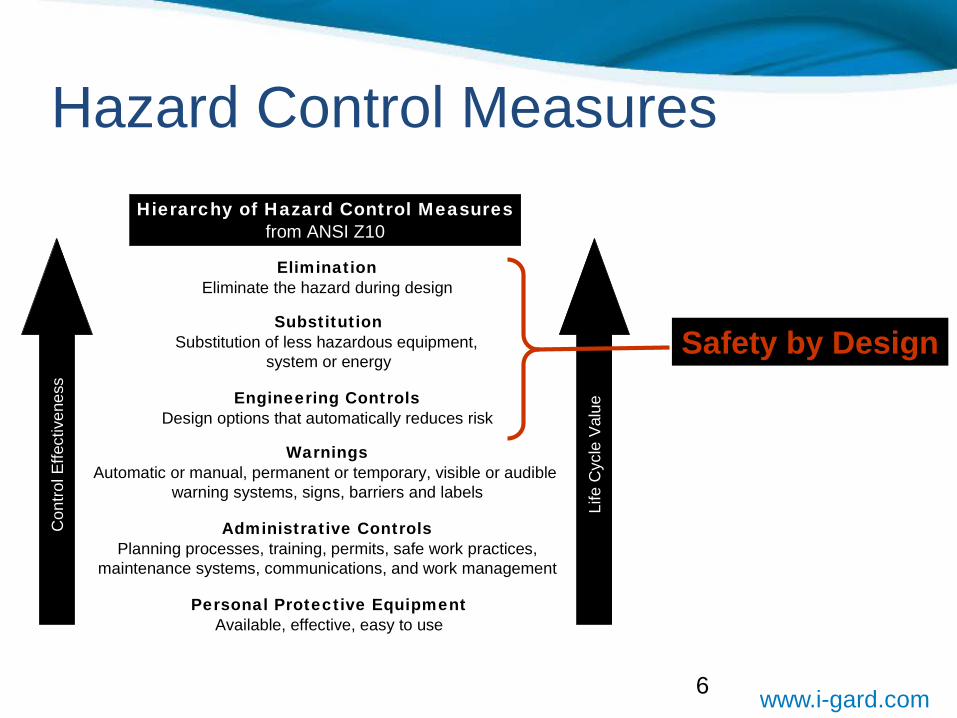
Hierarchy of Risk Controls Methods
• Informational Note No. 1: The hierarchy of risk control methods specified in ANSI/AIHA Z10, American National Standard for Occupational Health and Safety Management Systems, is as follows:
• (1) Elimination• (2) Substitution• (3) Engineering controls• (4) Awareness• (5) Administrative controls• (6) PPE

www.i-gard.com
First US consensus standard for a safety & health management system
Issued July 25, 2005Updated 2012
5
www.i-gard.com
Con
trol E
ffect
iven
ess
Hierarchy of Hazard Control Measuresfrom ANSI Z10
EliminationEliminate the hazard during design
Personal Protective EquipmentAvailable, effective, easy to use
SubstitutionSubstitution of less hazardous equipment,
system or energy
Administrative ControlsPlanning processes, training, permits, safe work practices,
maintenance systems, communications, and work management
Engineering ControlsDesign options that automatically reduces risk
WarningsAutomatic or manual, permanent or temporary, visible or audible
warning systems, signs, barriers and labels
Life
Cyc
le V
alue
Hazard Control Measures
Safety by Design
6

www.i-gard.com
Hazard Control Measuresoutlined in ANSI Z10
Elimination Substitution EngineeringControls
Warnings AdministrativeControls
PPE
Addressed in OSHA and NFPA 70E
ANSI Z10 provide the framework to enable decisions and actions in all hazard control measures
Addressed in 70E 2015 Annex O
7

www.i-gard.com
Hazard Control
Regardless of the specifics of the Hazard there are always the same two concerns:
Concern #1 How likely is it to happen?
Concern #2 How bad will it be?
RISK
IMPACT
Electrical injuries represent a serious workplace health and safety issue.

www.i-gard.com
Regardless of the specifics of the Hazard there are always the same two concerns:
Concern #1 How likely is it to happen? What is the RISK?
US Bureau of Labor Statistics indicate that there were nearly 6,000 fatal electrical injuries to workers in the US between 1992 and 2013.
BLS data also indicates there were 24,100 non-fatal electrical injuries from 2003 – 2012.
National Safety Council reported in its 2014 edition of Injury Facts that there were 961 fatal injuries from 2008 through 2010 due to exposure to electric current.
A study of electrical injuries over a 20 year period at a Texas burn center found that 40% of burns were electrical arc injuries.
Source : Occupational Injuries from Electric Shock and Arc Flash Events, The Fire Protection Research Foundation March 2015.
Hazard Control

www.i-gard.com
Regardless of the specifics of the Hazard there are always the same two concerns:
Concern #2 How bad will it be? What will be the IMPACT?
Washington State Department of Labor and Industries “Burn Injuries Facts” reported that worker’s compensation costs for 30 serious arc flash or blast burn injuries that took place between September 2000 and December 2005 were in excess of $1.3 million.
OSHA in 2014 estimates a value of $62,500 per non-fatal injury for workers performing electric distribution work (direct costs only).
American Society of Safety Engineers estimates that indirect costs may be as much as 20 times higher than direct costs.
Source : Occupational Injuries from Electric Shock and Arc Flash Events, The Fire Protection Research Foundation March 2015.
Hazard Control

www.i-gard.com
What is an Arc Flash?
According to NFPA 70E:
A dangerous condition associated with the release of energy caused by an electric arc.
A hazard beyond shock and electrocution.

www.i-gard.com
What is an Arc Flash?Electric arcing, commonly referred to as an arc flash, occurs when current passes through the air between two or more conducting surfaces or from conductors to ground.
(Workplace Safety Awareness Council) Electric arcing may produce temperatures as high as 35,000 degrees and may cause severe burns, hearing loss, eye injuries, skin damage from molten metal, lung damage and blast injuries.
Source : Occupational Injuries from Electric Shock and Arc Flash Events, The Fire Protection Research Foundation March 2015

www.i-gard.com
Arc Flash
What does it do?
It Affects morale !
It Causes outages !
It Results in Penalties from OSHA
It destroys equipment !
It hurts people !

www.i-gard.com
NFPA 70E Annex 0
General Design Requirements 0.2.1
Employers, facility owners, and managers who have responsibility for facilities and installations having electrical energy as a potential hazard to employees and other personnel should ensure that electrical hazards risk assessments are performed during the design of electrical systems and installations”

www.i-gard.com
NFPA 70E Annex 0
General Design Requirements 0.2.2
Design option decision should facilitate the ability to eliminate hazards or reduce risk by doing the following:
1. Reducing the likelihood of exposure
2. Reducing the magnitude or severity of exposure

www.i-gard.com

www.i-gard.com
ANSI Z10 Hierarchy

www.i-gard.com
ELIMINATION SUBSTITUTION ENGINEERING CONTROLS
WARNINGS ADMINISTRATIVE CONTROLS
PERSONAL PROTECTIVE EQUIPMENT
Eliminate the hazard during the design phase
Substitute for a lower energy level.
Reduce the magnitude of the hazard.
Design options thatautomatically reduce risk.
Increase distance away from hazard.
Automatic or manual, permanent or temporary, visible or audible warning systems, signs, barriers and labels.
Planning processes,training permits, safe work practices, maintenance systems, communications and work management
Available,effective, easy to use.
Hierarchy of Hazard Control Measures from ANSI Z10
Control effectiveness
Life Cycle Value

www.i-gard.com
Typical Approach to Arc Flash Safety
Undertake an arc flash study
Determine magnitude of arc flash hazard
Purchase appropriate levels of PPE
Apply and post warning labels specifying risk.

www.i-gard.com
Arc Flash Study is a Continuation of the Electrical Power System Study
1) Short Circuit AnalysisDetermine the fault current available throughout the plant2) Coordination StudyDesign system so that nearest upstream clearing device opens the fault3) Arc Flash AnalysisCalories determined by available fault current, opening time, and distance from the fault

www.i-gard.com
Device Coordination

www.i-gard.com
ARC Rating - A value of the energy necessary to pass through any given fabric to cause with 50% probability a second or third degree burn. This would not make me feel safe !
NFPA® has identified four FR hazardous risk category levels, which are numbered by severity from 1 to 4.Personal Protection Equipment is the level of arc flash protection clothing you must wear to protectagainst a minimum level of incident energy.

www.i-gard.com
0.2.2 Design option decisions should facilitate the ability to eliminate hazards or reduce risk by doing the following: (1)Reducing the likelihood of
exposure(2) Reducing the magnitude or severity of exposure(3) Enabling achievement of an electrically safe work condition

www.i-gard.com
(3) High-resistancegrounding. A great majorityof electrical faults are of thephase-to-ground type. High-resistance grounding willinsert an impedance in theground return path andbelow (at 5 kV nominal orbelow), leaving insufficientfault energy and therebyhelping reduce the arc flashhazard level. High-resistance grounding willnot affect arc flash energyfor line-to-line or line-to-line arcs.

www.i-gard.com
Reducing the Likelihood of ExposureHigh Resistance Grounding
How Does HRG reduce Arc Flash?
According to Industrial Power System Grounding Design Handbook - 95% of all electrical faults are phase to ground faults.
By limiting the fault current to a low level, 10 amps or less, there is insufficient current for the arc to re-strike and it self-extinguishes.
Source(Wye)
HRG CØ
BØAØ
N

www.i-gard.com
Reducing the Likelihood of ExposureHigh Resistance Grounding
IEEE Std 141-1993 (Red Book)7.2.2. High-resistance grounding provides the same advantages as ungrounded systems yet limits the steady state and severe transient over-voltages associated with ungrounded systems.
IEEE Std 242-1986 Recommended Practice for the Protection and Coordination of Industrial and Commercial Power Systems
7.2.5. Ungrounded systems offer no advantage over high-resistance grounded systems in terms of continuity of service and have the disadvantages of transient over-voltages, locating the first fault and burn-downs from a second ground fault. For these reasons, they are being used less frequently today than high-resistance grounded systems”

www.i-gard.com
FM Global 5-18 Protection of Electrical Equipment Single Phase and Other Related Faults
– In ungrounded systems a phase to ground fault often produces dangerous overvoltage…
– Sustained arcing faults in low voltage apparatus are often initiated by a single-phase fault to ground which results in extensive damage to switchgear and motor control centers.
FM Global 5-10 Protective Grounding for Electric Power Systems and Equipment
– 2.3.3.1 Unlike the ungrounded system the high resistance grounded system prevents transient overvoltage which can cause potential failure of insulation.
– 2.3.4.1 Convert ungrounded systems to high resistance grounded systems.
Reducing the Likelihood of ExposureHigh Resistance Grounding

www.i-gard.com
Ungrounded System
IEEE Standard 242-2001 (Buff Book)Recommended Practice for Protection and Coordination of Industrial and Commercial Power Systems
8.2.5 If this ground fault is intermittent or allowed to continue, the system could be subjected to possible severe over-voltages to ground, which can be as high as six to eight times phase voltage. Such over-voltages can puncture insulation and result in additional ground faults. These over- voltages are caused by repetitive charging of the system capacitance or by resonance between the system capacitance and the inductance of equipment in the system.

www.i-gard.com
Case Study
Automotive Facility Troy Michigan
• Phase to Ground voltage monitored for 4 weeks ungrounded and 4 weeks high resistance grounded.
• 485 events with peak voltage above 700 volts due to intermittent ground faults.
• Peak voltage 1050 volts
• Transients lead to insulation degradation.

www.i-gard.com
Impact of Transient Over-voltages
Insulation failure resulting in phase to phase fault and equipment damage in excess of $200k.

www.i-gard.com
Case StudyAutomotive Facility Troy MichiganPhase voltage ungrounded Phase voltage HRG
High level of transients485 peak events over 700 voltsPeak voltage 1050 volts
Transients controlled0 peak events over 700 voltsPeak voltage 660 volts

www.i-gard.com
Elimination of HazardArc Faults on Solidly Grounded Systems
IEEE Std 142-1991 (Green Book)Recommended Practice for Grounding of Industrial and Commercial Power Systems
1.4.3 The reasons for limiting the current by resistance grounding may be one or more of the following.
To reduce the arc blast or flash hazard to personnel who may have accidentally caused or who happen to be in close proximity to the ground fault.
IEEE Std 141-1993 (Red Book)Recommended Practice for Electric Power Distribution for Industrial Plants
7.2.2 There is no arc flash hazard, as there is with solidly grounded systems, since the fault current is limited to approximately 5A.
Another benefit of high-resistance grounded systems is the limitation of ground fault current to prevent damage to equipment.

www.i-gard.com
Solidly Grounded Systems
IEEE Std 242-2001 (Buff Book)• 8.2.2. One disadvantage of the solidly grounded system involves
the high magnitude of destructive, arcing ground-fault currents that can occur.
IEEE Std 141-1993 (Red Book)• 7.2.4. The solidly grounded system has the high probability of
escalating into a phase-to-phase or three-phase arcing fault, particularly for the 480V and 600V systems. The danger of sustained arcing for phase-to-ground fault…is also high for the 480V and 600V systems, and low or near zero for the 208V system.

www.i-gard.com
ELIMINATION SUBSTITUTION ENGINEERING CONTROLS
WARNINGS ADMINISTRATIVE CONTROLS
PERSONAL PROTECTIVE EQUIPMENT
Eliminate the hazard during the design phase
Substitute for a lower energy level.
Reduce the impact of the hazard.
Design options thatautomatically reduce risk.
Increase distance away from the hazard.
Automatic or manual, permanent or temporary, visible or audible warning systems, signs, barriers and labels.
Planning processes,training permits, safe work practices, maintenance systems, communications and work management
Available,effective, easy to use.
High Resistance Grounding
Hierarchy of Hazard Control Measures from ANSI Z10
Control effectiveness
Life Cycle Value

www.i-gard.com
(2) Arc flash relay. An arcflash relay typically uses lightsensors to detect the lightproduced by an arc flashevent. Once a certain level oflight is detected the relay willissue a trip signal to anupstream overcurrent device.

www.i-gard.com
Arc Damage versus Arc Duration
0 100 200 300 400 500 600 700o
1
2
3
4
5
6
7
8
9
Current kA
An arc is developed within milli-seconds and leads to the discharge of enormous amounts of destructive energy. The energy in the arc is directly proportional to the square of the short-circuit current and the time the arc takes to develop.
Reduce the Time,
Reduce the Damage,
Reduce the Incident Energy.
Surface smoke
Surface damage
Burn through

www.i-gard.com
Total Clearing Time is Critical
Reduce the Time Reduce the Damage Reduce the Incident Energy
-35 ms: no significant damage to persons or 2.9 Cal /cm2Switchgear, which can often be returnedto use after checking the insulation resistances
- 100ms: small damage, requires cleaning and possibly 8.31 Cal/cm2some minor repair likely
- 500ms: large damage both for persons and the 41.58 Cal/cm2switchgear, which must be partly replaced.
The arc burning time is the sum of the time to detect the arc and the time to open the correct breaker.
*Based on 50kA maximum bolted fault current on a 480 volt solidly grounded system @ 18 “ Working distance.

www.i-gard.com
Optical Arc Detection RelaysAn arc is accompanied by radiation in the form of light, sound, and heat.
Therefore, the presence of an arc can be detected by analyzing visible light, sound waves, andtemperature change.
To avoid erroneous trips, it is normal to use a short-circuit current detector along with one of the aforementioned arc indicators.
The most common pairing inNorth America is current and light and in Europe it is common to employ light and pressure.

www.i-gard.com
Arc Flash Relay

www.i-gard.com
Optical Arc Detection Relays
Protection Type Clearance Time Incident Energy
MCGG Over-Current 2.0 seconds 211 Cal / cm2
MCGG Instantaneous 0.45 seconds 47 Cal / cm2
Optical Arc Detection 0.084 seconds 9.0 Cal / cm2
• Assumes circuit breaker interrupting time of 5 cycles• Assumes 480V and 65kA bolted fault current, 18 inches

www.i-gard.com
ELIMINATION SUBSTITUTION ENGINEERING CONTROLS
WARNINGS ADMINISTRATIVE CONTROLS
PERSONAL PROTECTIVE EQUIPMENT
Eliminate the hazard during the design phase
Substitute for a lower energy level.
Reduce the impact of the hazard.
Design options thatautomatically reduce risk.
Increase distance away from the hazard.
Automatic or manual, permanent or temporary, visible or audible warning systems, signs, barriers and labels.
Planning processes,training permits, safe work practices, maintenance systems, communications and work management
Available,effective, easy to use.
High Resistance Grounding
Arc Flash Detection Relay
Hierarchy of Hazard Control Measures from ANSI Z10
Control effectiveness
Life Cycle Value

www.i-gard.com
(1) Energy-reducing active arcflash mitigation system. Thissystem can reduce the arcingduration by creating a lowimpedance current path,located within a controlledcompartment, to cause thearcing fault to transfer to thenew current path, while theupstream breaker clears thecircuit. The system workswithout compromising existingselective coordination in theelectrical distribution system.

www.i-gard.com
Active Arc Mitigation
Arcing starts. The sensors detectthe arc.
The tripsignal is sent.
All the phases connected to ground.The arc is extinguished.
The shortcircuit current is disconnected within less than 3-5 cycles.

www.i-gard.com
Incident Energy without Arc Mitigation

www.i-gard.com
Incident Energy with Active Arc Mitigation
Fault clearing time: 3.1 ms ~ 1.17 cal/cm2
Introduction of an impedance controls the fault energy eliminating concern over mechanical stresses

www.i-gard.com
Over-Current
2.00 seconds
211 Cal / cm2
Instantaneous
0.45 seconds
47 Cal / cm2
Optical Arc Detection
0.084 seconds
9 Cal / cm2
I-Gard Shield
0.0031 seconds
1.17 Cal / cm2
Protection Type Clearance Time Incident Energy
• Assumes circuit breaker interrupting time of 5 cycles• Assumes 480V and 65kA bolted fault current, 18 inches
Reducing the Magnitude of ExposureActive Arc Mitigation

www.i-gard.com
ELIMINATION SUBSTITUTION ENGINEERING CONTROLS
WARNINGS ADMINISTRATIVE CONTROLS
PERSONAL PROTECTIVE EQUIPMENT
Eliminate the hazard during the design phase
Substitute for a lower energy level.
Reduce the impact of the hazard.
Design options thatautomatically reduce risk.
Increase distance away from the hazard.
Automatic or manual, permanent or temporary, visible or audible warning systems, signs, barriers and labels.
Planning processes,training permits, safe work practices, maintenance systems, communications and work management
Available,effective, easy to use.
High Resistance Grounding
Arc Flash Detection Relays and/or Active Arc Mitigation System
Hierarchy of Hazard Control Measures from ANSI Z10
Control effectiveness
Life Cycle Value

www.i-gard.com
0.2.2 Design option decisions should facilitate the ability to eliminate hazards or reduce risk by doing the following:
(1)Reducing the likelihood of exposure = High Resistance Grounding
(2) Reducing the magnitude or severity of exposure = arc flash relays or active arc mitigation.

www.i-gard.com
A great majority of electrical faults are of the phase-to-ground type. High resistance grounding will insert an impedance in the ground return path and will limit the fault current, leaving insufficient fault energy and thereby helping reduce the arc flash hazard.

www.i-gard.com
Engineering Controls: Remote SwitchingPermanently installed – remote mounted switches, mimic panels, SCADA systems
Advantages:
• Permanently mounted
• May already exist through SCADA systems
Disadvantages:
• Expensive to install
• Increased chance of operating the wrong breaker
• Requires cabinet or wall space located outside of the arc-flash hazard boundary of every breaker

www.i-gard.com
Engineering Controls: Remote SwitchingPortable – “Chicken Switch®” motor operated actuator with remote hand-held controller.
Advantages:
• No modification to switchgear – held in place with magnets
• One “Chicken Switch®” can be used on many breakers
• No additional space required in substation
• Most cost effective solution in most all cases
• Reduced chance of operating the wrong breaker
• Models are available for pistol-grip control switches, pushbuttons, and low voltage power circuit breakers
Disadvantages:
• Not permanently installed

www.i-gard.com
ELIMINATION# 1.
SUBSTITUTION#2.
ENGINEERING CONTROLS #3.
WARNINGS#4
ADMINISTRATIVE CONTROLS #5
PERSONAL PROTECTIVE EQUIPMENT
Eliminate the hazard during the design phase
Substitute for a lower energy level.
Reduce the impact of the hazard.
Design options thatautomatically reduce risk.
Increase distance away from the hazard.
Automatic or manual, permanent or temporary, visible or audible warning systems, signs, barriers and labels.
Planning processes,training permits, safe work practices, maintenance systems, communications and work management
Available,effective, easy to use.
High Resistance Grounding
Arc Flash Detection Relays and/or Active Arc Mitigation System
Remote rackingand remote switching
Arc flash warning labels
PPE clothing
Hierarchy of Hazard Control Measures from ANSI Z10
Control effectiveness
Life Cycle Value

www.i-gard.com

www.i-gard.com
Thank You
Questions?
For comments or product information, please contact: [email protected]


![mlit.go.jp · 2019. 2. 1. · [235] [235) 123 [24.2] [240] [240] [24.3] [242 [242 [242] [242) [245 43] [242 (242 [242] [24.2] [ú.2] [242] [242 [240] [242] 27 087 087 [24.6] [24.6]](https://img.dokumen.tips/doc/110x75/613019b41ecc51586943e0fb/mlitgojp-2019-2-1-235-235-123-242-240-240-243-242-242-242.jpg)