Embed Size (px)
Citation preview

453-HDBK-GN (formerly STDN No. 724)
450/EXPLORATION AND SPACE COMMUNICATIONS PROJECTS DIVISION
Ground Network Tracking and Acquisition Data
Handbook
Original
Publication Date: May 2007
Expiration Date: May 2012
Goddard Space Flight Center
Greenbelt, MarylandNational Aeronautics and
Space Administration
THIS DOCUMENT IS UNCONTROLLED WHEN PRINTED. CHECK THE GSFC CENTRALIZED CONFIGURATION MANAGEMENT SYSTEM AT: http://gdms.gsfc.nasa.gov/
PRIOR TO USE TO VERIFY THAT THIS IS THE CORRECT VERSION PRIOR TO USE.


a0389fm iii/(iv blank) 453-HDBK-GN
Preface
This document is under the configuration management of the Goddard Space Flight Center (GSFC) Ground Network (Code 453) Configuration Control Board (CCB). Proposed changes to this document shall be submitted to the Code 453 CCB along with supportive material justifying the proposed change. This document may be changed by Documentation Change Notice (DCN) or by complete revision. Questions concerning this document and proposed changes shall be addressed to: Project Manager Code 453 Goddard Space Flight Center Greenbelt, Maryland 20771

a0389fm v/(vi blank) 453-HDBK-GN
Change Information Page
List of Effective Pages Page Number Issue
Title iii thru xiii/(xiv blank) 1-1/(1-2 blank) 2-1 thru 2-9/(2-10 blank) 3-1 thru 3-41/(3-42 blank) 4-1 thru 4-25/(4-26 blank) 5-1 thru 5-7/(5-8 blank) 6-1 and 6-2 A-1 thru A-4 B-1 thru B-7/(B-8 blank) C-1 thru C-6 D-1 thru D-3/(D-4 blank) E-1 thru E-5/(E-6 blank) F-1 thru F-91/(F-92 blank) AB-1 thru AB-6
Original
Original
Original
Original
Original
Original
Original
Original
Original
Original
Original
Original
Original
Original
Original
Document History
Document Number Status/Issue Publication Date
CCR Number
STDN No. 724, Revision 5 453-HDBK-GN
Retired Original
March 1990 May 2007
453/165

a0389fm vii/(viii blank) 453-HDBK-GN
DCN Control Sheet
DCN Number
Date/Time Group (Teletype Only)
Month/ Year
Section(s) Affected
Initials

a0389toc.doc ix 453-HDBK-GN
Contents
Preface
Section 1. Introduction
1.1 Purpose and Scope ............................................................................................................ 1-1
1.2 Management Responsibility .............................................................................................. 1-1
1.3 References ......................................................................................................................... 1-1
1.4 Corrections and Improvements ......................................................................................... 1-1
Section 2. Network Tracking Systems
2.1 Ground Network Overview ............................................................................................... 2-1
2.2 GN Antenna Systems ......................................................................................................... 2-1
2.2.1 General .................................................................................................................. 2-1
2.2.2 System Equipment Capabilities ............................................................................. 2-1
2.2.3 System Configuration............................................................................................. 2-3
2.3 C-band Systems.................................................................................................................. 2-3
2.3.1 General .................................................................................................................. 2-3
2.3.2 System Equipment Capabilities ............................................................................ 2-3
2.3.3 Radar Characteristics.............................................................................................. 2-5
2.3.4 Other Radar Systems.............................................................................................. 2-6
2.4 Ranging Equipment............................................................................................................ 2-7
2.4.1 General .................................................................................................................. 2-7
2.4.2 SRE........................................................................................................................ 2-7
2.4.3 RER ....................................................................................................................... 2-7

a0389toc.doc x 453-HDBK-GN
Section 3. Spacecraft Acquisition Data
3.1 General .............................................................................................................................. 3-1
3.2 Acquisition Data Formats .................................................................................................. 3-2
3.2.1 General Overview ................................................................................................. 3-2
3.2.2 Acquisition Data Transmission ........................................................................... 3-28
3.2.3 Acquisition Data Processing .............................................................................. 3-33
3.2.4 LTAS .................................................................................................................. 3-34
3.3 Slaving Systems .............................................................................................................. 3-39
3.3.1 Intrasite Slaving System ...................................................................................... 3-39
Section 4. Tracking Data Formats and Reduction Algorithms
4.1 General .............................................................................................................................. 4-1
4.2 Low-speed Tracking Data Formats ................................................................................... 4-1
4.2.1 General .................................................................................................................. 4-1
4.2.2 Universal Tracking Data Format ........................................................................... 4-1
4.2.3 USSTRATCOM B3 Type 2 Radar Data Format ................................................... 4-7
4.2.4 46-character Radar Data Format ........................................................................... 4-9
4.3 High-speed Tracking Data Formats ................................................................................ 4-12
4.3.1 General ................................................................................................................ 4-12
4.3.2 Minimum Delay Data Format ............................................................................. 4-12
4.3.3 High-speed Universal Tracking Data Format ..................................................... 4-17
Section 5. Computer Program Applications
5.1 General .............................................................................................................................. 5-1
5.2 Tracking and Acquisition Programs .................................................................................. 5-1
5.2.1 S-band Tracking Processor System ....................................................................... 5-1
5.2.2 Metric Pointing Assembly ..................................................................................... 5-3
5.2.3 Tracking, Telemetry, and Command Processor .................................................... 5-3
5.3 Data Correction System Applicability .............................................................................. 5-4
5.3.1 TPS S-band (Angle Data Correction) .................................................................... 5-4
5.3.2 RTPS Computer System ........................................................................................ 5-5

a0389toc.doc xi 453-HDBK-GN
5.4 Masking ............................................................................................................................. 5-7
5.5 System Applicability ......................................................................................................... 5-7
Section 6. Magnetic Tape Formats and Usage 6.1 Introduction ....................................................................................................................... 6-1
6.2 Tape Block Formats and Tape Operation ......................................................................... 6-1
6.3 Tape Block Types .............................................................................................................. 6-1
6.3.1 Tape Block Type 1: Dynamic System Status Tape (RTPS or STPS) .................. 6-1
6.3.2 Tape Block Type 2 (RTPS or STPS) .................................................................... 6-2
6.3.3 Tape Block Type 3 (RTPS or STPS) .................................................................... 6-2
6.3.4 Tape Block Type 4 (RTPS) ................................................................................... 6-2
6.3.5 Tape Block Type 5 (STPS) ................................................................................... 6-2
Figures
2-1 Typical 9-meter RER Station Configuration...................................................................... 2-4
2-2 SRE Configuration, S-band................................................................................................ 2-8
2-3 RER Configuration............................................................................................................. 2-9
3-1. IRV Message Body, Five-level (Baudot) Format ............................................................... 3-3
3-2. IRV Message Body, Eight-level (ASCII) Format ............................................................... 3-3
3-3. IIRV Message Body Format ............................................................................................... 3-5
3-4. EPV TTY Message Body Format ....................................................................................... 3-9
3-5. 4800-bit Block EPV Format ............................................................................................. 3-10
3-6. Five-level Coded INP Format with Angles Only ............................................................. 3-19
3-7. Eight-level Coded (ASCII) INP Format with Angles Only ............................................. 3-20
3-8. Five-level Coded INP Format with Range ....................................................................... 3-24
3-9. Eight-level Coded INP Format with Range ...................................................................... 3-25
3-10. Five-level INP Format with Doppler Frequency Field ................................................... 3-25
3-11. USSTRATCOM Two-line Orbital Element Format ...................................................... 3-26
3-12. Illustration of IIRV Data Words Packed into the Data Field of 4800 Block Format....... 3-29
3-13. Illustration of IIRV ASCII Characters Packed into the 4800 Block................................ 3-30
3-14. Illustration of EPV Data Words Packed into the Data Field of 4800 Block Format ....... 3-31
3-15. Illustration of EPV ASCII Characters Packed into the 4800 Block................................. 3-32

a0389toc.doc xii 453-HDBK-GN
3-16. Launch Trajectory Acquisition System 2400-b/sec Data Format .................................... 3-38
3-17. Intrasite Slaving System................................................................................................... 3-41
4-1. USSTRATCOM B3 Type 2 Radar Data Format ............................................................... 4-7
4-2. C-band 46-character Radar Data Format ............................................................................ 4-9
4-3 Packing of 46-character C-band LSR Data ....................................................................... 4-11
4-4. MDDF Format .................................................................................................................. 4-13
4-5 4800-bit Data Block Structure ........................................................................................... 4-18
4-6. Packing of LSR Data Sample (Universal Format) ........................................................... 4-22
4-7. Packing of HSR Data Field (Universal Format) ............................................................... 4-23
5-1. Typical USB TPS Configuration......................................................................................... 5-2
Tables
2-1. C-band Radar Slew Capabilities ......................................................................................... 2-6
3-1. Station Acquisition Data Format Processing Capabilities ................................................. 3-1
3-2. TTY Symbol Definitions .................................................................................................... 3-2
3-3. IRV Message Body Explanation ....................................................................................... 3-4
3-4. IIRV ASCII TTY Message Body Explanation ................................................................... 3-6
3-5. EPV Message Body Explanation ..................................................................................... 3-11
3-6. EPV Acknowledgment Message ...................................................................................... 3-18
3-7. Explanation of INP Format ............................................................................................... 3-21
3-8. Explanation of USSTRATCOM Two-line Orbital Element Format ................................ 3-27
3-9. Explanation of Launch Trajectory Acquisition System 2400-b/sec Format ................... 3-35
3-10. ISS Slaving Capabilities ................................................................................................. 3-40
4-1. Universal Tracking Data Format ........................................................................................ 4-2
4-2. System-unique Modes ........................................................................................................ 4-5
4-3. Explanation of USSTRATCOM B3 Type-2 Radar Data Format ....................................... 4-8
4-4. Explanation of Radar 46-character Format ...................................................................... 4-10

a0389toc.doc xiii/(xiv blank) 453-HDBK-GN
4-5. Explanation of MDDF Format ......................................................................................... 4-14
4-6. 4800-bit Block Structure, Tracking Data ......................................................................... 4-19
4-7. Source Circuit ID Codes (Octal) ...................................................................................... 4-24
6-1. Speed and Density Combinations........................................................................................ 6-1
Appendix A. Determination of the Local Topocentric Vector at a Tracking Station
Appendix B. Antenna Angular Relations
Appendix C. Station/Tracker IDs
Appendix D. Vehicle Identification Assignment Conventions
Appendix E. Tracking Data Format Capabilities
Appendix F. Status Block Types
Abbreviations and Acronyms

1-1/(1-2 blank) 453-HDBK-GN
Section 1. Introduction
1.1 Purpose and Scope This handbook specifies acquisition and tracking data exchanged between the Ground Network (GN) tracking and acquisition systems and the Flight Dynamics Facility (FDF) or other providers. It includes acquisition data and tracking data, both high-speed and low-speed, along with formats, program applications, data reduction algorithms, and station characteristics. Both real-time and recorded data are addressed.
1.2 Management Responsibility Goddard Space Flight Center (GSFC) Code 453 is the designated authority exercising management responsibility for maintenance of this document.
1.3 References a. Ground Network User’s Guide, 453-GNUG, Revision 2, May 2007.
b. System Specification for the S-Band Tracking Processing System, STDN 203.34, September 2005.
c. NASA Directory of Station Locations (NDOSL), http://fdf.gsfc.nasa.gov/prod_center/
d. Mission Station Information System (MSIS), https://msis.gsfc.nasa.gov/
e. NASA Communications Operating Procedures (NASCOP), Volume 1,452-006.
f. Digital Data/ Source/Destination and Format Codes Handbook for the NISN/Nascom Ground Network, GSFC-NISN-COM-99-0001.
1.4 Corrections and Improvements
1.4.1 Revisions to this document are prepared and published on an as-required basis. Interim changes, additions, and/or deletions are made by Documentation Change Notice (DCN).
1.4.2 Corrections and/or improvement recommendations are solicited and should be submitted to the Code 453 Ground Network Project Manager.

2-1 453-HDBK-GN
Section 2. GN Tracking Systems
2.1 Ground Network Overview The Ground Network consists of NASA-owned and commercial facilities.
a. Alaska Ground Station (AGS), Alaska, USA
b. Alaska Satellite Facility (ASF), Alaska, USA
c. DataLynx, various sites
d. Hartebeesthoek (HBK), South Africa
e. Merritt Island (MIL)/Ponce de Leon (PDL) Florida, USA
f. McMurdo Ground Station (MGS), Antarctica
g. Santiago (AGO), Chile
h. Svalbard Ground Station (SGS) Norway
i. Wallops Ground Station (WGS), Virginia, USA
j. Universal Space Network (USN), various sites
2.2 GN Antenna Systems
2.2.1 General
The support functions that can be performed with the GN antenna systems include tracking, telemetry, command, air-ground voice, and television capabilities. Technical capabilities of the GN antennas are described in Ground Network User’s Guide, 453-GNUG. Detailed antenna characteristics are also available on-line from the Mission Station Information System (MSIS). (http://msis.gsfc.nasa.gov/)
2.2.2 System Equipment and Capabilities
2.2.2.1 Angle Tracking (9-m antenna)
The S-band systems employ monopulse autotrack principles to generate error signals for application to the antenna servo/computer system and thereby maintain the antenna pointed toward the spacecraft transmitted signal. To aid in initial acquisition, a program (computer-controlled) mode is also available. The program mode uses orbital prediction data to generate angle data for the antenna. Antenna angle readings are compared with predicted angles, and corresponding error signals are generated. In addition, the 9-m initial acquisition of the spacecraft Radio Frequency (RF) signal may be facilitated by means of a small, wider beamwidth acquisition parabolic antenna, mounted at the edge of the 9-m antennas. Other antenna operating modes include manual position and velocity, slave, and manual program. The X-Y mounts are capable of tracking through zenith but have a gimbal restriction keyhole near
2-2 453-HDBK-GN
the horizon. This restriction is generally oriented north to south on 9-m antennas. Antenna coverage patterns are further restricted at most stations by the surrounding terrain.
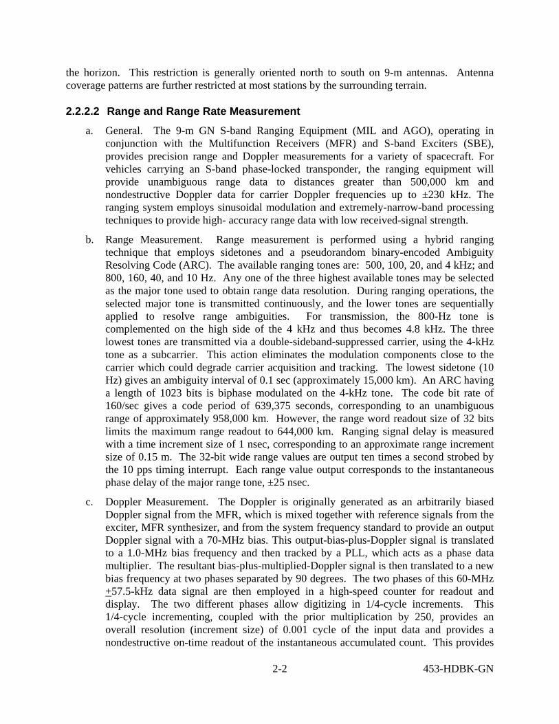
2.2.2.2 Range and Range Rate Measurement
a. General. The 9-m GN S-band Ranging Equipment (MIL and AGO), operating in conjunction with the Multifunction Receivers (MFR) and S-band Exciters (SBE), provides precision range and Doppler measurements for a variety of spacecraft. For vehicles carrying an S-band phase-locked transponder, the ranging equipment will provide unambiguous range data to distances greater than 500,000 km and nondestructive Doppler data for carrier Doppler frequencies up to ±230 kHz. The ranging system employs sinusoidal modulation and extremely-narrow-band processing techniques to provide high- accuracy range data with low received-signal strength.
b. Range Measurement. Range measurement is performed using a hybrid ranging technique that employs sidetones and a pseudorandom binary-encoded Ambiguity Resolving Code (ARC). The available ranging tones are: 500, 100, 20, and 4 kHz; and 800, 160, 40, and 10 Hz. Any one of the three highest available tones may be selected as the major tone used to obtain range data resolution. During ranging operations, the selected major tone is transmitted continuously, and the lower tones are sequentially applied to resolve range ambiguities. For transmission, the 800-Hz tone is complemented on the high side of the 4 kHz and thus becomes 4.8 kHz. The three lowest tones are transmitted via a double-sideband-suppressed carrier, using the 4-kHz tone as a subcarrier. This action eliminates the modulation components close to the carrier which could degrade carrier acquisition and tracking. The lowest sidetone (10 Hz) gives an ambiguity interval of 0.1 sec (approximately 15,000 km). An ARC having a length of 1023 bits is biphase modulated on the 4-kHz tone. The code bit rate of 160/sec gives a code period of 639,375 seconds, corresponding to an unambiguous range of approximately 958,000 km. However, the range word readout size of 32 bits limits the maximum range readout to 644,000 km. Ranging signal delay is measured with a time increment size of 1 nsec, corresponding to an approximate range increment size of 0.15 m. The 32-bit wide range values are output ten times a second strobed by the 10 pps timing interrupt. Each range value output corresponds to the instantaneous phase delay of the major range tone, ±25 nsec.
c. Doppler Measurement. The Doppler is originally generated as an arbitrarily biased Doppler signal from the MFR, which is mixed together with reference signals from the exciter, MFR synthesizer, and from the system frequency standard to provide an output Doppler signal with a 70-MHz bias. This output-bias-plus-Doppler signal is translated to a 1.0-MHz bias frequency and then tracked by a PLL, which acts as a phase data multiplier. The resultant bias-plus-multiplied-Doppler signal is then translated to a new bias frequency at two phases separated by 90 degrees. The two phases of this 60-MHz +57.5-kHz data signal are then employed in a high-speed counter for readout and display. The two different phases allow digitizing in 1/4-cycle increments. This 1/4-cycle incrementing, coupled with the prior multiplication by 250, provides an overall resolution (increment size) of 0.001 cycle of the input data and provides a nondestructive on-time readout of the instantaneous accumulated count. This provides

2-3 453-HDBK-GN
nondestructive Doppler data with a uniform 0.1-sec sampling interval. Doppler counts can be continuously accumulated for 150 minutes at the maximum Doppler.
d. Rate-aided Tracking. Rate-aided tracking permits use of a narrow bandwidth, range-tone tracking Phase-lock Loop (PLL) with severe signal dynamics. A rate-aid signal is synthesized from the extracted Doppler- plus-bias signal with a fractional error of 1 part in 176,000 or less. As a result, the PLL bandwidth can be very narrow to minimize noise error in the output range data without incurring excessive lag error for range acceleration magnitudes of 150 m/sec
2 or less.
2.2.3 System Configuration
Both AGO and MILA have S-band Tracking Processor Systems (STPSs) for assembling and transmitting metric tracking data and controlling and pointing its associated antenna. Figure 2-1 illustrates a typical 9-meter RER configuration.
2.3 C-band Systems
2.3.1 General
The GN C-band radar tracking systems are amplitude-comparison, monopulse instrumentation systems which measure range, azimuth, and elevation of spacecraft. Included in this discussion are non-GN C-band radars which provide special tracking support for National Aeronautics and Space Administration (NASA) launches.
2.3.2 System Equipment and Capabilities
2.3.2.1 FPS-16 Radar
The FPS-16 radar has a 3.6-m diameter parabolic antenna mounted on an az-el pedestal. The antenna reflector surface consists of wire mesh panels supported by radial trusses. The antenna has a four-horn monopulse feed, supported on a tetrapod, located at the focal point of the antenna reflector.

453-HD
BK
-GN
Figure 2-1. Typical 9-meter RER Station Configuration
9-METER

a0389s1.doc 2-5 453-HDBK-GN
2.3.2.2 MIPIR Systems
The FPQ-6, FPQ-14, FPQ-19, and TPQ-18 radars are all classified as Missile Precision Instrumentation Radars (MIPIR) and utilize the same basic electronics configuration. A MIPIR is second generation to the FPS-16 radar and offers several major improvements such as tracking capability to greater distances, greater angle track precision, and rapid detection and lock-on of target. The antenna is an aluminum, parabolic, Cassegrain feed system with a solid surface and a diameter of 8.8 meters mounted on an az-el pedestal. The MIPIR was originally designed in two versions, the FPQ-6 in which the electronic equipment is housed within permanent buildings, and the TPQ-18 housed in modular shelters to enhance transportability of the system. Subsequent changes have resulted in additional configurations and designations as follows: (1) The FPQ-14 offers all FPQ-6 improvements and is computer integrated with the on-axis system; (2) The FPQ-19 is a former TPQ-18 that has been relocated to a permanent building.
2.3.2.3 FPQ-15 and TPQ-18 (M) Radars
The FPQ-15 and TPQ-18 (M) radars are functionally similar to the FPQ-14 radar but utilize a NIKE Target Tracking Radar (TTR) pedestal.
2.3.2.4 CAPRI and HAIR
The Compact All-purpose Range Instrument (CAPRI) radar evolved from the MIPIR and was designed to fill the specialized needs for range instrumentation radars. The standard CAPRI was delivered with a 12-ft antenna but could be delivered with any size pedestal/antenna confi-guration. The MTLC is equipped with a 16-ft antenna while the HAIR (VDHC) is equipped with the TPQ-18/FPQ-6 antenna. The transmitter power on both of these systems is 1 MW.
2.3.2.5 The Advanced Research Project Agency, Lincoln C-band Observable Radar (ALCOR)
ALCOR is a high-power, narrowbeam, coherent, and chirped C- band monopulse system capable of simultaneous skin and beacon tracking. It provides azimuth, elevation, range, and range rate data. It has a range accuracy of 0.5 m in narrowband mode, 0.1 m in wideband mode, and an angle accuracy of 0.005 degree. ALCOR has a 12.2-m diameter parabolic antenna with a gain of 54 dB and a beamwidth of 0.3 degree. The peak power output of the ALCOR radar is 4 MW, with an average power of 10 kW.
2.3.3 Radar Characteristics
2.3.3.1 There is some variance in the characteristics of the individual radars even though they have the same model designator. For example, a significant variance in the AN/FPS-16 models is the different antenna size which results in different gain and beamwidth characteristics. Also, some systems have 3.0 MW transmitters in place of the 1.0 MW transmitters. Each of the radars is similar in that the receive systems employ low-noise receivers or parametric amplifiers with a noise figure of about 3.5 dB, they all have digital designate capability, and all are operated in the 5400- to 5900-MHz band. (The AN/FPS-16 1.0 MW transmitter operates in the range of 5450 to
a0389s1.doc 2-6 453-HDBK-GN
5825 MHz; the MIPIR from 5400 to 5900 MHz.) Detailed and up-to-date antenna characteristics are available on-line from the Mission Station Information System (MSIS). (http://msis.gsfc.nasa.gov/)
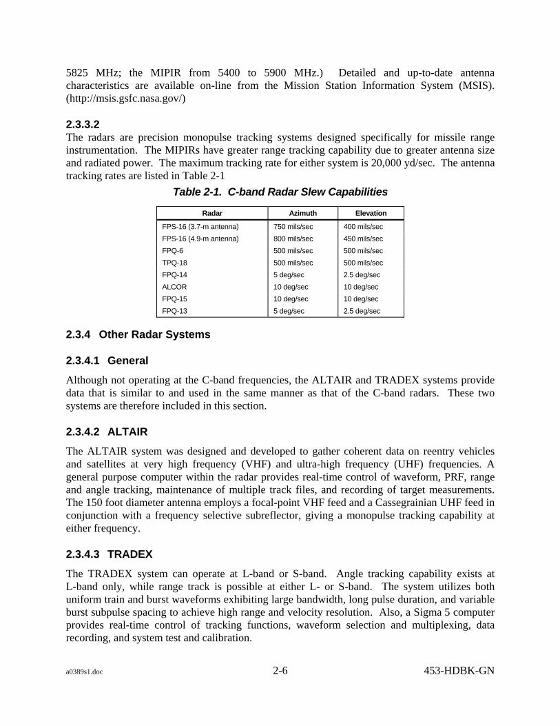
2.3.3.2 The radars are precision monopulse tracking systems designed specifically for missile range instrumentation. The MIPIRs have greater range tracking capability due to greater antenna size and radiated power. The maximum tracking rate for either system is 20,000 yd/sec. The antenna tracking rates are listed in Table 2-1
Table 2-1. C-band Radar Slew Capabilities
Radar Azimuth Elevation
FPS-16 (3.7-m antenna) 750 mils/sec 400 mils/sec FPS-16 (4.9-m antenna) 800 mils/sec 450 mils/sec FPQ-6 500 mils/sec 500 mils/sec TPQ-18 500 mils/sec 500 mils/sec FPQ-14 5 deg/sec 2.5 deg/sec ALCOR 10 deg/sec 10 deg/sec FPQ-15 10 deg/sec 10 deg/sec FPQ-13 5 deg/sec 2.5 deg/sec
2.3.4 Other Radar Systems
2.3.4.1 General
Although not operating at the C-band frequencies, the ALTAIR and TRADEX systems provide data that is similar to and used in the same manner as that of the C-band radars. These two systems are therefore included in this section.
2.3.4.2 ALTAIR
The ALTAIR system was designed and developed to gather coherent data on reentry vehicles and satellites at very high frequency (VHF) and ultra-high frequency (UHF) frequencies. A general purpose computer within the radar provides real-time control of waveform, PRF, range and angle tracking, maintenance of multiple track files, and recording of target measurements. The 150 foot diameter antenna employs a focal-point VHF feed and a Cassegrainian UHF feed in conjunction with a frequency selective subreflector, giving a monopulse tracking capability at either frequency.
2.3.4.3 TRADEX
The TRADEX system can operate at L-band or S-band. Angle tracking capability exists at L-band only, while range track is possible at either L- or S-band. The system utilizes both uniform train and burst waveforms exhibiting large bandwidth, long pulse duration, and variable burst subpulse spacing to achieve high range and velocity resolution. Also, a Sigma 5 computer provides real-time control of tracking functions, waveform selection and multiplexing, data recording, and system test and calibration.

a0389s1.doc 2-7 453-HDBK-GN
2.3.4.4 Configuration and Allocation
The NDOSL (http://fdf.gsfc.nasa.gov/prod_center/) provides radar allocation and station ID information.
2.4 Ranging Equipment
2.4.1 General
Ranging data is provided by various stations by means of STDN Ranging Equipment (SRE) or Receiver-exciter Ranging (RER). The RER equipment is used with Unified S-band (USB) system only, whereas the SRE may be configured for S-band. A station may have one or both of these systems as described in the following paragraphs.
2.4.2 SRE
2.4.2.1 General
SRE ranging in S-band (see Figure 2-2) can be provided by AGO. The Major Range Tone (MRT) frequencies available are 500, 100, and 20 kHz. The MRT is the highest frequency tone used in ranging support and is uplinked continuously. Of these, the 100-kHz and 20-kHz tones can also be used as the Minor Tone (MT), along with 4 kHz, 800 Hz, 160 Hz, 40 Hz, 10 Hz, and the Ambiguity Resolving Code (ARC).
2.4.2.2 S-Band
SRE ranging in S-band only is available at AGO. The configuration is as shown in Figure 2-2, with the 7-m antenna being used for uplink and the 12-m antenna being used for downlink.
2.4.3 RER
The RER configuration, as shown in Figure 2-3, is used with USB systems only. This type of ranging is available from AGO and MIL. The RER utilizes the same MRTs and MTs as the SRE.

a0389s1.doc 2-8 453-HDBK-GN
Figure 2-2. SRE Configuration, S-band
2-9
7M 12M
TDPS

a0389s1.doc 2-9/(2-10 blank) 453-HDBK-GN
Figure 2-3. RER Configuration

a0389s3.doc 3-1 453-HDBK-GN
Section 3. Spacecraft Acquisition Data
3.1 General This section defines acquisition data formats used by the GN stations. Station processing capabilities are tabulated in Table 3-1.
Table 3-1. GN Station Acquisition Data Format Processing Capabilities
Station IIRV INP IRV TLE LTAS
AGO X X X
AGS X X
ASF X X
DataLynx X X
HBK X
MGS X * X
MIL X x X X
SGS X X
USN X X X
WGS X X X X
* INP capability July 2007
3.2 Acquisition Data Formats
3.2.1 General Overview
Acquisition data formats consist of IRV, IIRV, EPV, INP, and Two Line Element (TLE) Message. Acquisition data is available in both low- and high-speed formats. The standard symbol definitions used in the low-speed format descriptions are listed in Table 3-2. In the figures and tables provided for the explanations of formats, all uppercase letters (except CAN and DEL) are fixed characters and are printed as they appear. Lowercase letters are variables which are defined in the tables.

a0389s3.doc 3-2 453-HDBK-GN
Table 3-2. TTY Symbol Definitions Symbol Definition
< Carriage return º Line feed _ Space
DEL Delete (ASCII) CAN Cancel (ASCII)
- Figures shift (Baudot) ¯ Letters shift (Baudot) $ Numeral - Sign of parameter
3.2.1.1 Interrange Vector Message
a. An IRV contains the position and velocity of a spacecraft at a given time in rotating geocentric coordinates. Checksums are provided for each of the position and velocity components and for the epoch time. In computing these checksums, 0 through 9 have face value; the ampersand (&), used to denote a positive sign, has a value of zero; and the minus (-), used to denote a negative sign, has a value of 1.
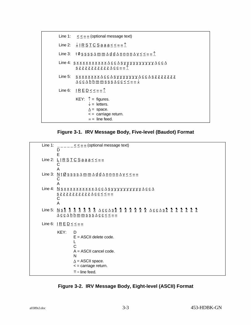
b. The IRV may be transmitted in either five-level format or eight-level TTY code (see Figures 3-1 and 3-2). If the eight-level format is converted to five-level code, the format will convert to that shown for the five-level format; however, if the five-level format is converted to eight-level format, each figure shift will be converted to a cancel code and each letter shift will be converted to a delete code. Refer to Table 3-3 for IRV message body description.
c. IRVs/IIRVs may be used to compute pointing angle information for any known antenna location. IRVs/IIRVs are not usually restricted to a specific pass but may be used over a limited period of time which is determined by the orbit of the satellite.
3.2.1.2 Improved Interrange Vector Message
a. The IIRV was implemented on the networks in 1978. The means of transmission may be either low-speed 110-baud teletype or high-speed Nascom blocked format. The IIRV is coded in American Standard Code for Information Interchange (ASCII). Although no parity checks are made on individual characters at Goddard Space Flight Center (GSFC), parity may be required for message switching between Nascom and other communications networks.
b. All data fields are right justified, with leading zeros added as needed. A positive sign (+) is indicated by an ASCII space, and a negative sign is indicated by a minus (-). The IIRV format is also used for intercenter exchange of acquisition data in Nascom 4800-bit blocks. Refer to paragraph 3.2.2.2 for further details.
c. In addition to containing the spacecraft position and velocity vectors for the given epoch time, the IIRV also contains information about the type of vector as well as additional spacecraft parameters. See Figure 3-3 for the IIRV message body format and refer to Table 3-3 for IIRV message body explanation.
a0389s3.doc 3-3 453-HDBK-GN
Line 1: < < ≡ ≡ (optional message text)
Line 2: ↓ I R S T C S a a a < < ≡ ≡ ↑
Line 3: t 0/ s s s s ∆ m m ∆ d d ∆ n n n n ∆ v < < ≡ ≡ ↑
Line 4: s x x x x x x x x x x ∆ c c ∆ s y y y y y y y y y y ∆ c c ∆ s z z z z z z z z z z ∆ c c ≡ ≡ ↑
Line 5: s x x x x x x x ∆ c c ∆ s y y y y y y y ∆ c c ∆ s z z z z z z z ∆ c c ∆ h h m m s s s ∆ c c < < ≡ ≡ ↓
Line 6: I R E D < < ≡ ≡ ↑ KEY: ↑ = figures.
↓ = letters. ∆ = space. < = carriage return. ≡ = line feed.
Figure 3-1. IRV Message Body, Five-level (Baudot) Format
Line 1: _ _ _ _ _ < < ≡ ≡ (optional message text) D E Line 2: L I R S T C S a a a < < ≡ ≡ C A Line 3: N t Ø s s s s ∆ m m ∆ d d ∆ n n n n ∆ v < < ≡ ≡ C A Line 4: N s x x x x x x x x x x ∆ c c ∆ s y y y y y y y y y y ∆ c c ∆ s z z z z z z z z z z ∆ c c < < ≡ ≡ C A Line 5: N s x• x• x• x• x• x• x• ∆ c c ∆ s y• y• y• y• y• y• y• ∆ c c ∆ s z• z• z• z• z• z• z• ∆ c c ∆ h h m m s s s ∆ c c < < ≡ ≡ Line 6: I R E D < < ≡ ≡ KEY: D E = ASCII delete code. L C A = ASCII cancel code. N ∆ = ASCII space. < = carriage return. ≡ = line feed.
Figure 3-2. IRV Message Body, Eight-level (ASCII) Format

a0389s3.doc 3-4 453-HDBK-GN
Table 3-3. IRV Message Body Explanation (1 of 2)
Line Characters Explanation 1 ------------- Optional message text 2 IRSTCS
aaa
Start of message (fixed) Range address. Up to three characters indicating addressee: D = DSN P = PMR S = STDN W = WTR E = ETR Z = WLP A = CSTC K = KMR
3 t 0/ ssss mm dd nnnn v
Vector type: 1 = nominal 2 = in flight 3 = powered flight 4 = simulated
Always zero (fixed) Satellite SIC Month of year Day of month Sequence number VID.
4 s xxxxxxxxxx cc s yyyyyyyyyy cc s zzzzzzzzzz cc
Sign of X component X component in feet Checksum for X component Sign of Y component Y component in feet Checksum for Y component Sign of Z component Z component in feet Checksum for Z component. Digits 0 through 9 have face value, the - (minus) sign has a value of 1, and the & (ampersand) sign and spaces have values of 0.

a0389s3.doc 3-5 453-HDBK-GN
Table 3-3. IRV Message Body Explanation (2 of 2)
Line Characters Explanation 5 s
x• x• x• x• x• x• x• cc s y• y• y• y• y• y• y• cc s z• z• z• z• z• z• z• cc hhmmsss cc
Sign of X-velocity component X-velocity component in 1/100 ft/second Checksum for X component Sign of Y-velocity component Y-velocity component in 1/100 ft/second Checksum for Y component Sign of Z-velocity component Z-velocity component in 1/100 ft/second Checksum for Z component (see definition in line 4) Epoch time of IRV in hours, minutes, seconds, and 1/10 seconds Checksum of time word (see definition in line 4)
6 IRED End of message (fixed)
Line 1: _ _ _ _ _ < < ≡ ≡ (optional message text) Line 2: G I I R V a r r r r < < ≡ ≡ s s s s i i i i Line 3: v s 1 c c c c c b b n n n d o y h h m m s s s s s c c c < < ≡ ≡ Line 4: s x x x x x x x x x x x x s y y y y y y y y y y y y s z z z z z z z z z z z z c c c < < ≡ ≡
Line 5: s x• x• x• x• x• x• x• x• x• x• x• x• s y• y• y• y• y• y• y• y• y• y• y• y• s z• z• z• z• z• z• z• z• z• z• z• z• c c c < < ≡ ≡ Line 6: m m m m m m m m a a a a a k k k k s r r r r r r r c c c < < ≡ ≡ Line 7: I T E R M _ o o o o < < ≡ ≡ KEY: < Carriage Return ≡ Line Feed ∆ ASCII Space
Figure 3-3. IIRV Message Body Format

a0389s3.doc 3-6 453-HDBK-GN
Table 3-4. IIRV ASCII TTY Message Body Explanation (1 of 2)
Line Characters Explanation 1 _ _ _ _ Optional message text.
2 GIIRV Start of message (fixed). a Alphabetic character indicating originator of message:
ASCII space = GSFC Z = WLP E = ETR L = JPL W = WTR J = JSC P = PMR A = CSTC K = KMR C = CNES
rrrr Destination routing indicator. Specifies the site for which the message was generated. If for more than one station, this field should contain "MANY."
3 v Vector type: 1 = Free flight (routine on-orbit) 2 = Forced (special orbit update) 3 = Spare 4 = Maneuver ignition 5 = Maneuver cutoff 6 = Reentry 7 = Powered flight 8 = Stationary 9 = Spare
s Source of data: 1 = Nominal/planning 2 = Real-time 3 = Off-line 4 = Off-line/mean
NOTE Nominal/planning sets cannot be sent to WSGT from the NCC.
1 Fixed one (1) c Coordinate system:
1 = Geocentric True-of-Date Rotating 2 = Geocentric mean of 1950.0 (B1950.0). 3 = Heliocentric B1950.0. 4 = Reserved for JPL use (non-GSFC). 5 = Reserved for JPL use (non-GSFC). 6 = Geocentric mean of 2000.0 (J2000.0). 7 = Heliocentric J2000.0.
sic (4 chars) SIC bb Body number/VID (01-99). nnn Counter incremented for each vector in a set of vector data on a per-station per-
transmission basis. doy Day of year (001 = January 1). hhmmsssss Vector epoch in UTC with resolution to nearest millisecond. (The implied
decimal point is three places from the right). ccc Checksum of the decimal equivalent of the preceding characters on Line 3:
0 through 9 = face value. Minus (-) = 1. ASCII Space = 0.

a0389s3.doc 3-7 453-HDBK-GN
Table 3-4. IIRV ASCII TTY Message Body Explanation (2 of 2)
Line Characters Explanation 4 s Sign character:ASCII Space = positive
Minus sign = negative xxxxxxxxxxxx X component of position (meters) yyyyyyyyyyyy Y component of position (meters) zzzzzzzzzzzz Z component of position (meters) ccc Checksum of the decimal equivalent of the preceding characters on Line 4:
0 through 9 = face value Minus (-) = 1 ASCII Space = 0
5 s Sign character (same as above) x• x• x• x• x• x• x• x• x• x• x• x• X-component of velocity y• y• y• y• y• y• y• y• y• y• y• y• Y-component of velocity z• z• z• z• z• z• z• z• z• z• z• z• Z-component of velocity
NOTE All velocity components are in meters/second with resolution to the nearest millimeter/second. The implied decimal point is three places from the right.
ccc
Checksum of the decimal equivalent of the preceding characters on Line 5: 0 through 9 = face value Minus (-) = 1 ASCII Space = 0
6 mmmmmmmm Mass of spacecraft in kilograms with resolution to 1/10 of a kilogram. The implied decimal point is one place from the right. Contains all zeros when not used.
aaaaa Average spacecraft cross-sectional area in square meters with resolution to the nearest hundredth of a square meter. The implied decimal point is two places from the right. Contains all zeros when not used.
kkkk Dimensionless drag coefficient. The implied decimal point is two places from the right. Contains all zeros when not used.
s Sign character for coefficient of solar reflectivity ASCII Space = positive Minus Sign = negative
rrrrrrr Dimensionless Solar Reflectivity coefficient. The implied decimal point is six places from the right. Contains all zeros when not used.
ccc Checksum of the decimal equivalent of the preceding characters on Line 6: 0 through 9 = face value Minus (-) = 1 ASCII Space = 0
7 ITERM End of message (fixed) oooo Originator routing indicator

a0389s3.doc 3-8 453-HDBK-GN
3.2.1.3 Extended Precision Vector Message
a. General. The Extended Precision Vector (EPV) message described in this paragraph is the official version of the EPV along with the blocking structure for use with the Nascom 4800-bit block. The inclusion of the EPV in the document does not commit any entity that interfaces with the GSFC Code 450 to use it. Commitment for its use will be by individual Interface Control Documents (ICD) with specific Code 450 organizations. These ICDs should reference this document for the basic structure of the EPV message only and should identify each specific parameter options that is to be exercised. Additional specifics are as follow:
1. The EPV message format is intended to meet high-accuracy orbit propagation requirements. This has been achieved by increasing the precision of the state vector position and velocity components and by including additional force modeling parameters. The means of transmission may be either low-speed 110-band teletype or high-speed Nascom blocked format. The EPV is coded in ASCII. Although no parity checks are made on individual characters at GSFC, parity may be required for message switching between Nascom and other communications networks.
2. All data fields are right justified, with leading zeros added as needed. A positive sign (+) is indicated by an ASCII space, and a negative sign is indicated by a minus (-). The EPV format is also used for intercenter exchange of acquisition data in Nascom 4800-bit blocks. Refer to paragraph 3.2.2.2 for further details.
3. See Figure 3-4 for the EPV TTY message body format, and refer to Table 3-5 for the EPV message body explanation.
b. EPV Message Structure and Protocol.
1. Block Format. The block format used is defined in Figure 3-5. The block is segmented into six distinct parts: network control header, user header 1, time field, user header 2, data field, and error control field.
2. Network Control Header.
(a) The Nascom synchronization field, bits 1 through 24, is a 24-bit binary field with the following structure:
First bit transmitted 011000100111011000100111 Last bit transmitted
(b) The source field, bits 25 through 32, is an 8-bit field that describes the data source. Nascom assigns these codes (refer to NASA Communications Operating Procedures [NASCOP]).
(c) The destination field, bits 33 through 40, is an 8-bit binary field that describes the data destination. Nascom assigns these codes (refer to NASCOP).
(d) The sequence number field, bits 41 through 43, is a 3-bit field that identifies the sequence in which blocks were transmitted from a source. The range of this cyclic counter is 1 through 7.

Line 1: m t m e s s g i d s m c < < ≡ ≡ Line 2: G E P V a r r r r < < ≡ ≡ Line 3: v s o c e s i d c b b n n n y y y y d o y h h m m s s s s s s u t l u t c c c c < < ≡ ≡ Line 4: s x x x x x x x x x x x x x x x x x s y y y y y y y y y y y y y y y y y s
z z z z z z z z z z z z z z z z z c c c < < ≡ ≡
Line 5: s x• x• x• x• x• x• x• x• x• x• x• x• x• s y• y• y• y• y• y• y• y• y• y• y• y• y• s z• z• z• z• z• z• z• z• z• z• z• z• z• c c c < < Line 6: s o s c s e m i m a j o r a x i s s s o s c e c c e n t r i c s o s c i n c l i n a t n c c c < < ≡ ≡ Line 7: s o s c l o n a s n o d e s o s c a r g p e r i a p s o s c m e a n a n o m l
g r a v i t a t i o n a l p a r m c c c < < ≡ ≡ Line 8: m a s s m m m m d c s a r e a c s b d s d s c a l e p s c s a r e a s c s u b r f
s f l x i g m g a i c c c < < ≡ ≡ Line 9: _ _ _ _ _ _ _ _ _ _ _ _ _ _ _ _ _ _ _ _ _ _ _ _ _ _ _ _ _ _ _ _ _ _ _ _ _ _ _ _
_ _ _ _ _ _ _ _ _ _ _ _ _ _ _ _ _ _ _ _ _ < < ≡ ≡ Line 10: _ _ _ _ _ _ _ _ _ _ _ _ _ _ _ _ _ _ _ _ _ _ _ _ _ _ _ _ _ _ _ _ _ _ _ _ _ _ _ _
_ _ _ _ _ _ _ _ _ _ _ _ _ _ _ _ _ _ _ _ _ < < ≡ ≡ Line 11: _ _ _ _ _ _ _ _ _ _ _ _ _ _ _ _ _ _ _ _ _ _ _ _ _ _ _ _ _ _ _ _ _ _ _ _ _ _ _ _
_ _ _ _ _ _ _ _ _ _ _ _ _ _ _ _ _ _ _ _ _ < < ≡ ≡ Line 12: I T E R M 0 0 0 0 < < KEY: < = Carriage Return ≡ = Line Feed ∆ = ASCII Space
Figure 3-4. EPV TTY Message Body Format
3-9453-H
DB
K-G
N

a0389s3.doc 3-10 453-HDBK-GN
Figure 3-5. 4800-bit Block EPV Format
A0389024.DRW:X:N
1-16
17-32
33-48
49-64
65-80
81-96
97-112
113-128
129-144
145-160
161-176
177-192
4753-4768
4769-4784
4785-4800
0 1 1 0
* 1* 2* 3* 4* 5* 6* 7* 8* 9* 10* 11* 12* 13* 14* 15* 16* * * * * ** * * * * * * * * * * * * * * * *
0 0 1 0 0 1 1 1 0 1 1 0
0 0 1 0 0 1 1 1 SOURCE CODE
DESTINATION CODE
VEHICLE ID
SEQ No. FORMAT CODE
SPARE
DESTINATIONMESSAGE BLOCK TYPE
S S F BLOCK DATA LENGTH
UTC
BLOCK NUM MESSAGE BLOCK ID
SPARE NUM OF BLKS SPARE F1 F2 F3 F4 S
MESSAGE OR ACKNOWLEDGEMENT SUBFIELD(4592 BITS)
REMAINDER
SPARE P2P1 POLYNOMIAL
NETWORK******
HEADER
USER
HDR1
******
******
TIME
FIELD
******
USR
HD2
******
******
DATA
FIELD
ERR
FLD

a0389s3.doc 3-11 453-HDBK-GN
Table 3-5. EPV Message Body Explanation (1 of 5) Line Characters Explanation
1 MT Message type (= 03).
MESSGID Message ID. A unique seven-character number used to reference this message.
S Source (= 0).
MC Message class code: 20 =Routine on-orbit or stationary vector. 25 =Maneuver sequence vector or high-priority on-orbit or stationary vector.
CRCR Two carriage returns.
LFLF Two line feeds.
2 GEPV EPV message identifier.
A Alphabetic character indicating originator of message: G = GSFC Z = WLP E = ETR L = JPL W = WTR J = JSC P = PMR A = AFSTC K = KMR C = CNES
RRRR Destination routing indicator. Specifies the site for which the message was generated. If the message is for more than one station, this field contains "MANY"
CRCR Two carriage returns
LFLF Two line feeds
3 V Vector type: 1 = Routine on-orbit 2 = Special on-orbit update 3 = Spare 4 = Maneuver ignition 5 = Maneuver cutoff 6 = Reentry 7 = Powered flight 8 = Stationary 9 = Spare
S Data type: 1 = Nominal/planning 2 = Real-time
O Origin of coordinate system and reference plane: 1 = Geocentric, Earth equator 2 = Heliocentric, Earth equator 3 = Heliocentric, eclipic 4 = Selenocentric, Earth equator 5 = Selenocentric, Moon equator 6 through 9 = Spares
C Coordinate system: 1 = Greenwich true-of-date rotating 2 = Greenwich true-of-date nonrotating 3 = Mean-of-1950.0 (B1950.0) 4 = Mean-of-2000.0 (J2000.0) 5 = True-of-date (B1950.0) 6 = True-of-date (J2000.0) 7 = Selenographic. 8 and 9 = Spares.
E Types of elements only. 1 = Cartesian elements only 2 = Osculating elements only 3 = Both Cartesian and osculating elements
SIDC SIC
BB Body number of vehicle ID

a0389s3.doc 3-12 453-HDBK-GN
Table 3-5. EPV Message Body Explanation (2 of 5) Line Characters Explanation
3 (cont)
NNN Counter incremented for each vector in a set of vector data on a pre-station, per-transmission basis. For JSC, each mission is treated as a single transmission.
YYYY Year.
DOY Day of Year.
HHMMSSSSSS Vector epoch in UTC with resolution to the nearest tenth of a millisecond. The millisecond. The implied decimal point is four places from the right.
S Sign character: ASCII space = positive Minus sign = negative
UT1UTC UT1 = UTC timing coefficient at epoch with resolution to the nearest microsecond. The implied decimal point is six places from the right. This field will contain all zeros when not used
CCC Checksum of the decimal equivalents of each of the preceding characters on line 2: 0 through 9 = face value Minus (-) = 1 ASCII space = 0
CRCR Two carriage returns
LFLF Two line feeds
4 S Sign character: ASCII space = positive Minus sign = negative
NOTE
XXXXXXXXXXXXXXXXX X component of position All position components are in kilometers with resolution to the nearest tenth of a millimeter.
S Sign character: ASCII space = positive Minus sign = negative
The implied decimal point is seven places from the right.
YYYYYYYYYYYYYYYYY Y component of position These fields will contain all zeros when not used.
S Sign character: ASCII space = positive Minus sign = negative
ZZZZZZZZZZZZZZZZZ Z component of position
CCC Checksum. This is the sum of the decimal equivalents of all the preceding characters on line 3: 0 through 9 = face value Minus (-) = 1 ASCII Space = 0
CRCR Two carriage returns
LFLF Two line feeds
5 S Sign character: ASCII space = positive Minus sign = negative
NOTE
x• x• x• x• x• x• x• x• x• x• x• x• x• X component of velocity. All velocity components are in kilometers/second with resolution to the nearest tenth of a micron/second.
S Sign character ASCII space = positive Minus sign = negative
The implied decimal point is ten places from the right.
These fields will contain all zeros when not used.
y• y• y• y• y• y• y• y• y• y• y• y• y• Y component of velocity
S Sign character: ASCII space = positive Minus sign = negative
z• z• z• z• z• z• z• z• z• z• z• z• z• Z component of velocity

a0389s3.doc 3-13 453-HDBK-GN
Table 3-5. EPV Message Body Explanation (3 of 5) Line Characters Explanation
5 (cont)
CCC Checksum. This is the sum of the decimal equivalents of all the preceding characters on line 4: 0 through 9 = face value Minus (-) = 1 ASCII space = 0
CRCR Two carriage returns
LFLF Two line feeds
6 S Sign character: ASCII space = positive Minus sign = negative
OSCSEMIMAJORAXISS Osculating semimajor axis
S Sign character: ASCII space = positive Minus sign = negative
OSCECCENTRIC Osculating eccentricity
S Sign character: ASCII space = positive Minus sign = negative
OSCINCLINATN Osculating inclination
The semimajor axis is in kilometers with resolution to the nearest tenth of a millimeter. The implied decimal point is seven places from the right. The eccentricity is dimensionless with resolution to the nearest 10-10. The implied decimal point is ten places from the right. The inclination is in degrees with resolution to the nearest 10-9 degrees. The implied decimal point is nine places from the right. These fields will contain all zeros when not used.
CCC Checksum. This is the sum of the decimal equivalents of all the preceding characters on line 5. 0 through 9 = face value Minus (-) = 1 ASCII Space = 0
CRCR Two carriage returns
LFLF Two line feeds
7 S Sign character: ASCII space = positive Minus sign = negative
OSCLONASNODE Osculating longitude of the ascending node.
S Sign character: ASCII space = positive Minus sign = negative
OSCARGPERIAP Osculating argument of periapse
S Sign character ASCII space = positive Minus sign = negative
OSCMEANANOML Osculating mean anomaly
The longitude of the ascending node, the argument of perigee, and the mean anomaly are in degrees with resolution to the nearest 10-9 degrees. The implied decimal point is nine places from the right. These fields will contain all zeros when not used.
GRAVITATIONALPARM Gravitational parameter corresponding to Cartesian and osculating elements in units of kilometers3/second2 with resolution to the nearest 10-5 kilometers3/second2. The implied decimal point is five places from the right. This field will contain all zeros when not used.
CCC Checksum. This is the sum of the decimal equivalents of all the preceding characters on line 6: 0 through 9 = face value Minus (-) = 1 ASCII space = 0
CRCR Two carriage returns.
LFLF Two line feeds.
a0389s3.doc 3-14 453-HDBK-GN
Table 3-5. EPV Message Body Explanation (4 of 5) Line Characters Explanation
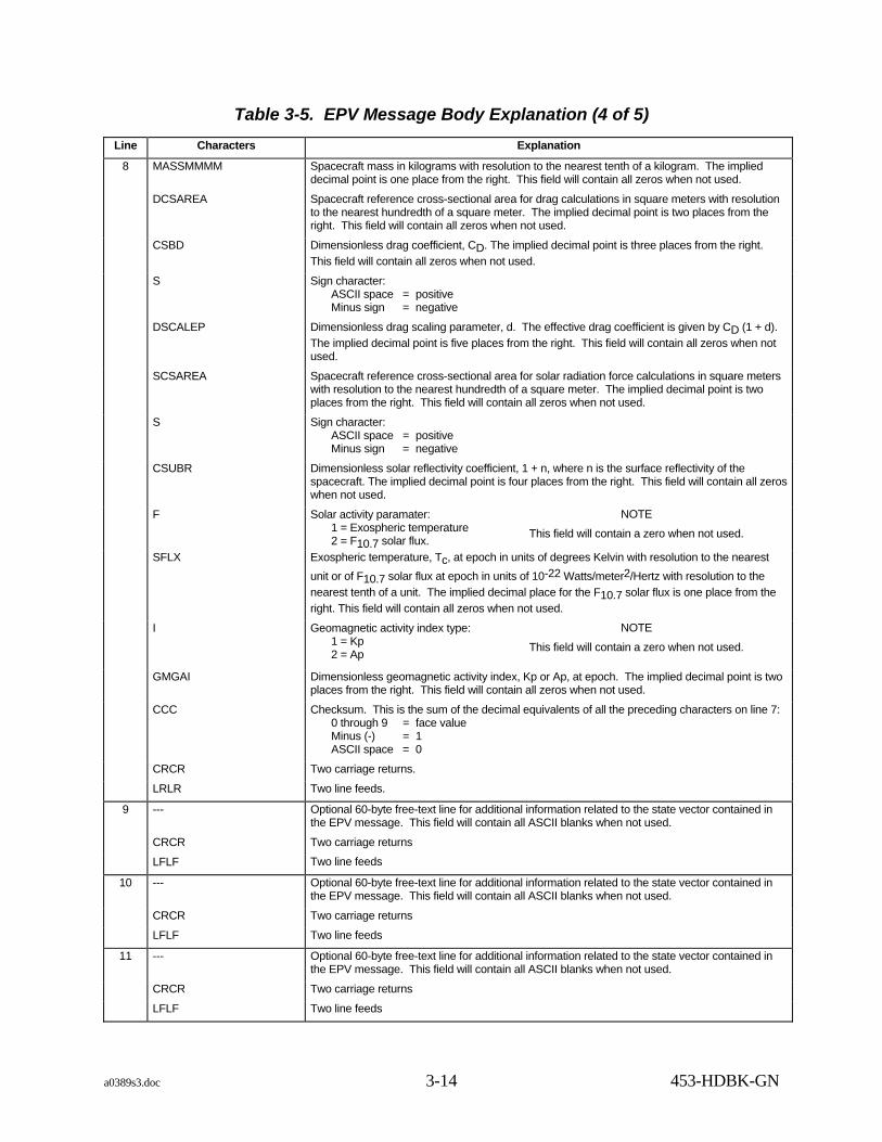
8 MASSMMMM Spacecraft mass in kilograms with resolution to the nearest tenth of a kilogram. The implied decimal point is one place from the right. This field will contain all zeros when not used.
DCSAREA Spacecraft reference cross-sectional area for drag calculations in square meters with resolution to the nearest hundredth of a square meter. The implied decimal point is two places from the right. This field will contain all zeros when not used.
CSBD Dimensionless drag coefficient, CD. The implied decimal point is three places from the right. This field will contain all zeros when not used.
S Sign character: ASCII space = positive Minus sign = negative
DSCALEP Dimensionless drag scaling parameter, d. The effective drag coefficient is given by CD (1 + d). The implied decimal point is five places from the right. This field will contain all zeros when not used.
SCSAREA Spacecraft reference cross-sectional area for solar radiation force calculations in square meters with resolution to the nearest hundredth of a square meter. The implied decimal point is two places from the right. This field will contain all zeros when not used.
S Sign character: ASCII space = positive Minus sign = negative
CSUBR Dimensionless solar reflectivity coefficient, 1 + n, where n is the surface reflectivity of the spacecraft. The implied decimal point is four places from the right. This field will contain all zeros when not used.
F Solar activity paramater: 1 = Exospheric temperature 2 = F10.7 solar flux.
NOTE
This field will contain a zero when not used.
SFLX Exospheric temperature, Tc, at epoch in units of degrees Kelvin with resolution to the nearest unit or of F10.7 solar flux at epoch in units of 10-22 Watts/meter2/Hertz with resolution to the nearest tenth of a unit. The implied decimal place for the F10.7 solar flux is one place from the right. This field will contain all zeros when not used.
I Geomagnetic activity index type: 1 = Kp 2 = Ap
NOTE
This field will contain a zero when not used.
GMGAI Dimensionless geomagnetic activity index, Kp or Ap, at epoch. The implied decimal point is two places from the right. This field will contain all zeros when not used.
CCC Checksum. This is the sum of the decimal equivalents of all the preceding characters on line 7: 0 through 9 = face value Minus (-) = 1 ASCII space = 0
CRCR Two carriage returns.
LRLR Two line feeds.
9 --- Optional 60-byte free-text line for additional information related to the state vector contained in the EPV message. This field will contain all ASCII blanks when not used.
CRCR Two carriage returns
LFLF Two line feeds
10 --- Optional 60-byte free-text line for additional information related to the state vector contained in the EPV message. This field will contain all ASCII blanks when not used.
CRCR Two carriage returns
LFLF Two line feeds
11 --- Optional 60-byte free-text line for additional information related to the state vector contained in the EPV message. This field will contain all ASCII blanks when not used.
CRCR Two carriage returns
LFLF Two line feeds

a0389s3.doc 3-15 453-HDBK-GN
Table 3-5. EPV Message Body Explanation (5 of 5) Line Characters Explanation
12 ITERM End of message.
0000 Originator routing indicator.
CRCR Two carriage returns.
LFLF Two line feeds.
--- Fill data (3118).
(e) The Nascom format field, bits 44 through 48, is a 5-bit field used to identify the type of data block. The EPV message must have a binary 01011 code in this field.
3. User Header 1.
(a) The Vehicle ID (VID) field, bits 49 through 56, is an 8-bit field that contains a code identifying the spacecraft to which the message block is related.
(b) The spare field, bits 57 through 64, is an 8-bit field that contains an all 1's pattern.
(c) The message block type field, bits 65 through 72, is an 8-bit field that contains a code that defines the specific type of data contained in the block. The EPV message must have a binary 10001100 code in this field.
(d) The destination code field, bits 73 through 80 is an 8-bit field that is reserved for a destination code that identifies the recipient of the data block and contains the same value as bits 33 through 40.
(e) Bits 81 and 82 are spare bits and are not used.
(f) Bit 83 is set to a binary 1, for the full block flag, to indicate that the block data field is completely used, or it is set to a binary 0 to indicate that the data field is less than full.
(g) The block data length binary field, bits 84 through 96, is a 13-bit field that contains the length, in bits, of user header 2 plus the data portion of the block. If the block is full, this field must contain the binary equivalent of 4624 bits.
4. Time Field. The use of the time field, bits 97 through 144, is optional. If used, it contains NASA PB4 time (refer to X-814-77-64). NCC-generated blocks must always contain a time code in this field. If this field does not contain a PB4 time code, it must be set to all binary 1's.
5. User Header 2.
(a) The message block number, bits 145 through 148, is a 4-bit field that contains an incrementing binary counter associated with a unique block ID to place blocks in the proper sequence in a multiblock group. The block count always starts at 1 and increments by 1 for each subsequent block in a multiblock group. A block count of 1 indicates that this block is the only block of a single-

a0389s3.doc 3-16 453-HDBK-GN
block message or the first block of a multiblock message. The maximum allowable value in this field is 15.
(b) The message block ID field, bits 149 through 160, is a 12-bit field that is used to define a unique message. The message block ID starts with an initial value of 1 and increments by 1 for successive messages. Message block ID assignment is controlled by the message originator. It should not be expected that sequential messages received at a destination will have sequential message block IDs.
(c) Bit 161 and 162 contain zeros.
(d) The number of blocks binary field, bits 163 through 166, is a 4-bit field that contains the number blocks constituting the message. The maximum number of blocks per message is 15. The number in this field must be the same in all blocks of a message.
(e) Bits 167 through 171 contain zeros.
(f) Message Block Flags.
(1) Five 1-bit flags, bits 172 through 176, are included in the header. These flags must be used to signify an acknowledge request, retransmitted block, acknowledgment enclosed, last block, and one spare bit. A flag set means that the bit equals a binary 1.
(2) The acknowledge request flag (F1), bit 172, is set to any message that requires an acknowledgment. The acknowledgment request flag will not be set in an acknowledgment message. An acknowledgment must be sent to the originator on receipt of a completed message having the acknowl-edgment request flag set. The FDF waits for the acknowledgment of one message before transmitting the next message. The acknowledge request flag is only valid in the first block of a multiblock group.
(3) The retransmitted block flag (F2), bit 173, is set in any retransmitted blocks. The original block number and ID are not altered by retransmis-sion.
(4) The acknowledgment enclosed flag (F3), bit 174, is set whenever bits 177 through 208 contain an acknowledgment.
(5) The last block indicator (F4), bit 175, must be set in the last block of a message and must be 0 in all preceding blocks.
(6) Bit 176 is zero.
6. Message Block Data Field. The message block data field, bits 177 through 4768, consists of either the message subfield of 4592 bits or the acknowledgment subfield of 144 bits.

a0389s3.doc 3-17 453-HDBK-GN
7. Message Subfield. This field consists of 574 8-bit bytes (4592 bits). Each byte contains an ASCII character. ASCII characters have the parity bit (bit 27) set to a zero. The parity bit occurs first in serial transmissions. For example, a message type of 02 (ASCII) appears as follows:
Bit 177 Bit 192 ↓ ↓ 0 0 1 1 0 0 0 0 0 0 1 1 0 0 1 0 ↑ ↑ Parity Parity
First bit in serial transmission
8. Acknowledgment Subfield.
(a) Bytes 23 through 26 are a duplication of bytes 19 through 22 of the last block of the message being acknowledged. This encompasses the data field previously described as follows:
(1) Block Number.
(2) Message block ID.
(3) Spare.
(4) Number of blocks.
(5) Spare.
(6) Block flags.
(b) Bytes 27 through 33 contain ASCII spaces. Bytes 34 through 40 contain a SUPIDEN code of Z9999ZZ.
9. Error Control Field.
(a) Bits 4769 through 4776 are spares.
(b) Bits 4777 and 4778 are used to indicate the detection of errors in a decoded block.
(c) Bits 4779 through 4800 contain a 22-bit polynomial remainder.
c. EPV Acknowledgment Protocol. On receipt of a complete EPV message requiring an acknowledgment, the receiver will transmit an acknowledgment to the originator in the next block transmission opportunity. The acknowledgment will repeat bytes 19 through 22 of the last block of the message being acknowledged and will always be sent in a separate, standalone message. The acknowledgment block will be an octal message block type (bits 65 to 72) of 113 (4B hexadecimal) for acknowledgments generated by the recipient. If a message is received with flag bit 2 (retransmitted message) set to a 1 and an acknowledgment required (flag bit 1 set to a 1), the receiver will acknowledge receipt of this message in the same manner as previously described. It is the receiver's responsibility to determine if this message has alreay been processed (i.e., same

a0389s3.doc 3-18 453-HDBK-GN
message block ID and source code). If so, the second copy of the message should not be processed.
d. EPV Acknowledgment Message. The format shown in Table 3-6 will be used for the transmission of an EPV message acknowledgment.
e. EPV Retransmission Protocol. On failure to receive an acknowledgment within 5 seconds of transmission of the last block of an EPV message, the originator will set the retransmitted block flag (F2) in each block of the message and retransmit the entire message. The first block of the retransmitted EPV message will be transmitted at the next transmission opportunity after any pending acknowledgment. The originator will retransmit all blocks of the EPV message in the order of ascending block sequence number. Retransmitted blocks will retain their original block number, block ID, and type. Failure to receive an acknowledgment for the first retransmission within 5 seconds will result in a second retransmission. Failure to receive an acknowledgment to the second retransmission within 5 seconds will result in an error indication being sent to the responsible operator and the termination of transmission for that particular SUPIDEN and EPV message.
f. EPVs may be used to compute pointing angle information for any known antenna location. EPVs are not usually restricted to a specific pass but may be used over a limited period of time which is determined by the orbit of the satellite.
Table 3-6. EPV Acknowledgment Message
Item Number
Number of Bytes
Data Item Range of Values
1 4 Acknowledgment SUBFIELD Bytes 19-22 from acknowledged message 2 7 Spare ASCII spaces 3 7 SUPIDEN Z9999ZZ
3.2.1.4 Internet Predict Message
a. The INP message contains predicted pointing data for a specific satellite pass and for a specific antenna. The INP body message is preceded by a Nascom header and followed by a Nascom trailer. The INP always contains angle information (see Figures 3-6 and 3-7 and refer to Table 3-7) and may include range information (see Figures 3-8 and 3-9 and refer to Table 3-7) and frequency information (see Figure 3-10.)
b. The INP must contain at least six data points (and not have more than 50 data points) which have the correct checksum calculations. In computing the checksums, 0 through 9 have face value, the ampersand (&), denoting a positive sign, has a value of 10; the minus (-), denoting a negative sign, has a value of 11.
c. The standard INP contains 30 points; however, 6 to 50 points are acceptable. The number of dynamic points is a function of request-zero or three and pass geometry-zero to three. The maximum angular difference between successive points should not exceed 5 degrees in the referenced coordinate system of the INP. If the Y axis exceeds

a0389s3.doc 3-19 453-HDBK-GN
plus or minus 79 degrees (keyhole), the 5-degree requirement can be disregarded. Each INP contains between 0 and 3 pre-acquisition of signal (AOS) and post-loss of signal (LOS) points (i.e., the elevation at the beginning and end of the message may be negative). For long passes, additional INPs are acceptable if the start time of the continued INP is greater than 30 minutes later than the AOS time of the original INP.
d. INPs are issued as Ground Elapsed Time (GET) or Greenwich Mean Time (GMT). An INP generated for GET time generates the points for time elapsed since liftoff with the time for liftoff being considered 000 days, 00 hours, 00 minutes, 00 seconds. INPs generated pre-mission are GET INPs. INPs generated GMT are real-time. GET INP messages are not regenerated unless the liftoff slips more than 30 days.
Line 1: ↑ $ ↓ I N P ↑ $ ∆ ↓ S E T ∆ a ↑ n n n n, ∆ ↓ M I S ∆ ↑ s s s s , ∆S C∆ ↑ v v , ∆ ↓ C H ∆ ↑ c c , ∆ ↓ S T A ∆ r ↑ i i < < ≡ ↓ Line 2: S C ∆ X M T ∆ ↑ f f f f . f f f f f f , ↓ S C ∆ R C V ∆ ↑ g g g g . g g g g g g , ↓ S T A ∆ X M T ∆ ↑ h h . h h h h h h , ↓ R G ∆ M O D ∆ ↑ r r r r r r < < ≡ ≡ ↓ Line 3: e e e ∆ ↑ y y , d d d , h h m m s s ∆ ∆ ∆ ↓ R T L T ∆ ↑ r r : t t : v v . v < < ≡ ↓ Line 4: f f f ∆ ↑ y y , d d d , h h m m s s ∆ ∆ ∆ ↓ R T L T ∆ ↑ r r : t t : v v . v < < ≡ ≡ ↓ Line 5: ∆ ∆ t t t ∆ ∆ ∆ a a a a a ∆ ∆ ∆ b b b b b ∆ ∆ ↓ C K < < ≡ ↑ Line 6 to Line n-1: h h m m s s ∆ a a a a a ∆ b b b b b ∆ c c < <≡ ↑ Line n: h h m m s s ∆ a a a a a ∆ b b b b b ∆ c c < < ≡ ≡ ↑ Line n+1: $ ↓ E N D ↑ $ ∆ ↓ S E T ∆ a ↑ n n n n , ∆ ↓ M I S _ ↑ s s s s , ∆ ↓ S C ∆ ↑ v v , ∆ ↓ C H ∆ ↑ c c , ∆ ↓ S T A ∆ r ↑ i i < < ≡ ↓ KEY: ↑ = Figures ↓ = Letters ∆ = Space ≡ = Line Feed < = Carriage Return
Figure 3-6. Five-level Coded INP Format with Angles Only

a0389s3.doc 3-20 453-HDBK-GN
Line 1: $ I N P $ ∆ S E T ∆ a n n n n , ∆ M I S ∆ s s s s , ∆ S C ∆ v v , ∆ C H ∆ c c, ∆ S T A ∆ r i i < < ≡ Line 2: S C ∆ X M T ∆ f f f f . f f f f f f , S C ∆ R C V ∆ g g g g . g g g g g g , S T A ∆ X M T ∆ h h . h h h h h h , R G ∆ MO D ∆ r r r r r r < < ≡ ≡ Line 3: e e e ∆ y y , d d d , h h m m s s ∆ ∆ ∆ R T L T ∆ r r : t t : v v .v < < ≡ Line 4: f f f ∆ y y , d d d , h h m m s s ∆ ∆ ∆ R T L T ∆ r r : t t : v v . v < < ≡ ≡ Line 5: ∆ ∆ t t t ∆ ∆ ∆ a a a a a ∆ ∆ ∆ b b b b b ∆ ∆ CK < < ≡ C Line 6 to A Line n-1: h h m m s s ∆ a a a a ∆ b b b b b ∆ c c < < ≡ N C A Line n: h h m m s s ∆ a a a a a ∆ b b b b b ∆ c c < < ≡ ≡ N D E Line n+1: $ E N D $ ∆ S E T ∆ a n n n n , ∆ M I S ∆ s s s s , ∆ S C ∆ v v , ∆ C H ∆ c c , ∆ S T A ∆ r i i < < ≡ L KEY: C A = Cancel N ∆ = ASCII Space < = Carriage Return = Line Feed D E = Delete L
NOTE
This is the format when the INP is generated directly in eight level. When converted from an original five-level INP into eight level, the up and down arrows in the five-level format (see Figure 3-4) will appear in their corresponding positions in the eight-level format as follows: C D ↑ = A ↓ = E = N L
Figure 3-7. Eight-level Coded (ASCII) INP Format with Angles Only

a0389s3.doc 3-21 453-HDBK-GN
Table 3-7. Explanation of INP Format (1 of 4)
Line Characters Explanation Fixed Variable 1 $INP$ Start of message SET SET a Alphabetic character specifying generator of data:
a. G = FDF/RLT f. W = WTR b. S = FDF/NON-RLT g. P = PMR c. J = JSC h. K = KMR d. L = JPL i. Z = WLP e. E = ETR
nnnn Predict set number (message sequence number), consisting of four alphanumeric characters and necessary upper and lower case teletype shift characters
MIS Mission ssss SIC, consisting of four numeric characters. Cannot be all zeros SC Spacecraft vv VID, consisting of two numeric characters (refer to appendix D).
Cannot be 00 CH Channel cc Channel identification number 01-99 is now defined as:
Trajectory Identification Number 01-19 =ON ORBIT - SOURCE OR DESTINATION OF DATA
where: 01 = premission nominal (source) 02 = real time (source) 03 = offline (source) 00 = not used
20-79 = launch trajectory variations 80-99 = entry and landing
STA Alphabetic character indicating the range for which the message is generated: a. A = CSTC e. P = PMR b. D = DSN f. S = STDN c. E = ETR g. W = WTR d. K = KMR h. Z = WLP Station identification, consisting of two numeric characters. Refer to Appendix C or NDOSL (http://fdf.gsfc.nasa.gov/prod_center/)
2 SC XMT Spacecraft transmit ffff.ffffff Spacecraft transmit frequency in MHz SC RCV Spacecraft receive gggg.gggggg Spacecraft receive frquency in MHz STA XMT Station transmit hh.hhhhhh Station transmission frequency in MHz RG.MOD Range modules (ambiguities) rrrrrr Number of range modules subtracted from the range value

a0389s3.doc 3-22 453-HDBK-GN
Table 3-7. Explanation of INP Format (2 of 4)
Line Characters Explanation Fixed Variable 3 eee Three alphabetic characters identifying the event used as the
start of the message. Valid entries are: AOS: Usually indicates horizon break. SOP: (Start of Predicts); Indicates that the start of the INP
does not correspond to a particular event. EMG: (Emergence); Time of spacecraft coming out of
occultation with a celestial body CON: (Continuation); Used when message follows another
INP which contains data points previous to these (see Note). Used by DOD radars only
NOTE
STDN TDPS-equipped stations cannot process continuation INPs. The TDPS stops processing at the last point in any message and will not automatically process any continuation received. Operator action is required to begin processing of continuation INP.
RTLT yy,ddd,hhmmss UTC of the event described in eee field. (ddd) cannot be all zeros Round trip light time
rr:tt:vv.v Round trip light time at time specified by yy,ddd,hhmmss field in hours, minutes, seconds, and tenths of seconds
4 fff Three alphabetic characters identifying the event used as the end of message. Valid entries are:
LOS: Loss of signal due to spacecraft going below station horizon
EOP: End of predicts indicates that the end of INP does not correspond to a particular event
OCC: Occultation predicts end due to spacecraft going behind a celestial body
TBC: Indicates that predicts to be continued in another INP (see Note for line 3). Used by DOD radars only
yy,ddd,hhmmss UTC of the event described in fff field. ddd cannot be all zeros RTLT Round trip light time rr:tt:vv.v Round trip light time at time specified by yy,ddd,hhmmss field in
hours, minutes, seconds, and tenths of seconds 5 NOTE
Line 5 entries are column headers for lines 6 through n. The range and Doppler information is optional and may not appear on all INPs. See Figure 3-8 for sample INP with Doppler frequency fields.
ttt Indicates GET or GMT

a0389s3.doc 3-23 453-HDBK-GN
Table 3-7. Explanation of INP Format (3 of 4)
Line Characters Explanation Fixed Variable
aaaaa Up to five alphanumeric characters indicating the coordinate system for angle 1. Valid entries are: a. Eight-level
AZI D X30 E L D X85 E L b. Five-level AZI X ↑ 30 ↓ X ↑ 85 ↓
NOTE These entries must correspond respectively to the entries selected for aaaaa field.
CK Checksum NOTE
See Figure 3-8 for example of Doppler frequency fields R Range rrrr Up to four alphabetic characters with appropriate upper and
lower case shift indicating the units for range field. Valid entries are:
a. KMS _ (kilometers). b. KYD _ (kiloyards). c. NMI _ (nautical miles). d. MCS _ (microseconds).
D1 DOP D1 = predicted one-way Doppler frequency measured at the Doppler extractor. R1 = one-way Doppler frequency measured at the receiver Voltage-controlled Oscillator (VCO). S1 = one-way Doppler at S-band.
D2 DOP D2 = predicted two-way Doppler frequency measured at the Doppler extractor.
R2 = two-way Doppler frequency measured at the receiver VCO. S2 = two-way Doppler frequency at S-band.
D3XXX D3 = three-way Doppler frequency. XXX is the station transmitting to the spacecraft.
R3 = three-way Doppler frequency at the receiver VCO. XXX is the station transmitting to the spacecraft.
S3 = three-way Doppler frequency at S-band. XXX is the station transmitting to the spacecraft.
tx vco Doppler frequency of the uplink Signal at the transmitter VCO. NOTE
Doppler frequencies in Hertz.

a0389s3.doc 3-24 453-HDBK-GN
Table 3-7. Explanation of INP Format (4 of 4)
Line Characters Explanation Fixed Variable
6 through
hhmmss Six numeric characters specifying the UTC hours, minutes, and seconds of the point.
n aaaaa Angle 1 value in 1/100 degree. For X85 and X30, the first character is the sign of the angle where & (ampersand) indicates positive, - (minus) indicates negative. For azimuth, signs are not required, zeros are used to fill unused character positions; i.e., 8.46 deg az = 00846, + 7.31 deg x = &0731
bbbbb Angle 2 value in 1/100 degree. For ELE, Y85, and Y30, the first character is the sign of the angle where & (ampersand) indicates positive, - (minus) indicates negative. Zeros are used to fill unused character positions; i.e., 7.31 deg Y or EL = &0731
cc Checksum computed on digits in the aaaaa and bbbbb fields. 0 through 9 carry face value, (&) = 10 and (-) = 11
rrrrrrr One-way range in 1/10 units specified in column header (line 5) ddddddddd For D1, D2 and D3 actual Doppler frequency measured at
Doppler extractor. For R1, R2, and R3 readings assume a leading 2 before the MSD for S1, S2, and S3
fffffffff Frequency measurement assumes a leading 1 NOTE
All Doppler frequency measurements are in hundredths of Hertz with the decimal point assumed between the second and third digits from the right. The MSD is in megahertz
n+1 $END$ End of message. (The rest of line n + 1 is a repetition of line 1.)
Line 1: ↑ $ ↓ I N P ↑ $ ∆ ↓ S E T ∆ a ↑n n n n , ∆ ↓ M I S ∆ ↑ s s s s , ∆ ↓ S C ∆ ↑ v v , ∆ ↓ C H ∆ ↑ cc , ∆ ↓ S T A ∆ r ↑ i i < < ≡ ↓
Line 2: S C ∆ X M T ∆ ↑ f f f f . f f f f f f , ↓ S C ∆ ↑ R C V ∆ g g g g . g g g g g g , ↓ S T A ∆ X M T ∆ ↑ h h . h h h h h h ↓ , R G ∆ M O D ∆ ↑ r r r r r r < < ≡ ≡ ↓
Line 3: e e e ∆ ↑ y y , d d d , h h m m s s ∆ ∆ ∆ ↓ R T L T ∆ ↑ r r : t t : v v . v < < ≡ ↓
Line 4: f f f ↑ y y , d d d , h h m m s s ∆ ∆ ∆ ↓ R TL T ∆ ↑ r r : t t : v v . v < < ≡ ≡ ↓
Line 5: ∆ ∆ t t t ∆ ∆ ∆ a a a a a ∆ ∆ ∆ b b b b b ∆ ∆ ↓ C K ∆ ∆ R ↑ . ↓ r r r r < < ≡ ↑
Line 6 to Line n-1: h h m m s s ∆ a a a a a ∆ b b b b b ∆ c c ∆ r r r r r r r < < ≡ ↑
Line n: h h m m s s ∆ a a a a a ∆ b b b b b ∆ c c ∆ r r r r r r r < < ≡ ≡ ↑
Line n+1: $ ↓ E N D ↑ $ ∆ ↓ S E T ∆ a ↑ n n n n , ∆ ↓ M I S ∆ ↑ s s s s , ∆ ↓ S C v ↑ v v , ∆ ↓ C H ∆ ↑ c c , ∆ ↓ S T A ∆ r ↑ i i < < ≡ ↓
KEY:
↑ = Figures
↓ = Letters
∆ = Line Feed
≡ = Line Feed
< = Carriage Return
Figure 3-8. Five-level Coded INP Format with Range

a0389s3.doc 3-25 453-HDBK-GN
Line 1: $ I N P $ _ S E T _ a n n n n n , _ M I S _ s s s s , _ S C _ v v , _ C H _ c c , _ S T A _ r i i < < ≡
Line 2: S C _ X M T _ f f f f . f f f f f f , S C _ R C V _ g g g g . g g g g g g , S T A _ X M T _ h h . h h h h h h , R G _ M O D _ r r r r r r < < ≡ ≡
Line 3: e e e _ y y , d d d , h h m m s s _ _ _ R T L T _ r r : t t : v v . v < < ≡
Line 4: f f f↑ y y , d d d , h h m m s s _ _ _ R T L T _ r r : t t : v v . v < < ≡ ≡
Line 5: _ _ t t t _ _ _ a a a a a _ _ _ b b b b b _ _ C K _ _ R . r r r r < < ≡
C Line 6 to A Line n-1: h h m m s s _ a a a a a _ b b b b b _ c c _ r r r r r r r < < ≡ N
C A Line n: h h m m s s _ a a a a a _ b b b b b _ c c _ r r r r r r r < < ≡ ≡ N
D E Line n+1: $ E N D $ _ S E T _ a n n n n , _ M I S _ s s s s , _ S C _ v v , _ C H _ c c , _ S T A _ r i i < < ≡ L KEY:
C A = Cancel N ∆ = Space ≡ = Line Feed < = Carriage Return D E = Delete L
NOTE
This is the format when the INP is generated directly in eight level. When converted from an original five-level INP into eight level, the up and down arrows in the five-level format (see Figure 3-6) will appear in the corresponding positions in the eight-level format as follows:
C D ↑ = A ↓ = E N L
Figure 3-9. Eight-level Coded INP Format with Range
Line 5: ∆ ∆ t t t ∆ ∆ ∆ a a a a a ∆ ∆ b b b b b ∆ ∆ ↓ C K _ _ R ↑ , ↓ r r r r ∆ ∆ ∆ D ↑ 1 . ↓ D O P ∆ ∆ ∆ ∆ D ↑ 2 . ↓ D O P ∆ ∆ ∆ ∆ D ↑ 3 . ↓ X X X X ∆ ∆ ∆ ∆ T X ↑ . ↓ V C O < < ≡ ↑ Line 6 to Line N: h h m m s s ∆ a a a a a ∆ b b b b b ∆ c c ∆ r r r r r r r ∆ d d d d d d d d d ∆ d d d d d d d d d ∆ d d d d d d d d d ∆ f f f f f f f f f < < ≡ ↑
Figure 3-10. Five-level INP Format with Doppler Frequency Field
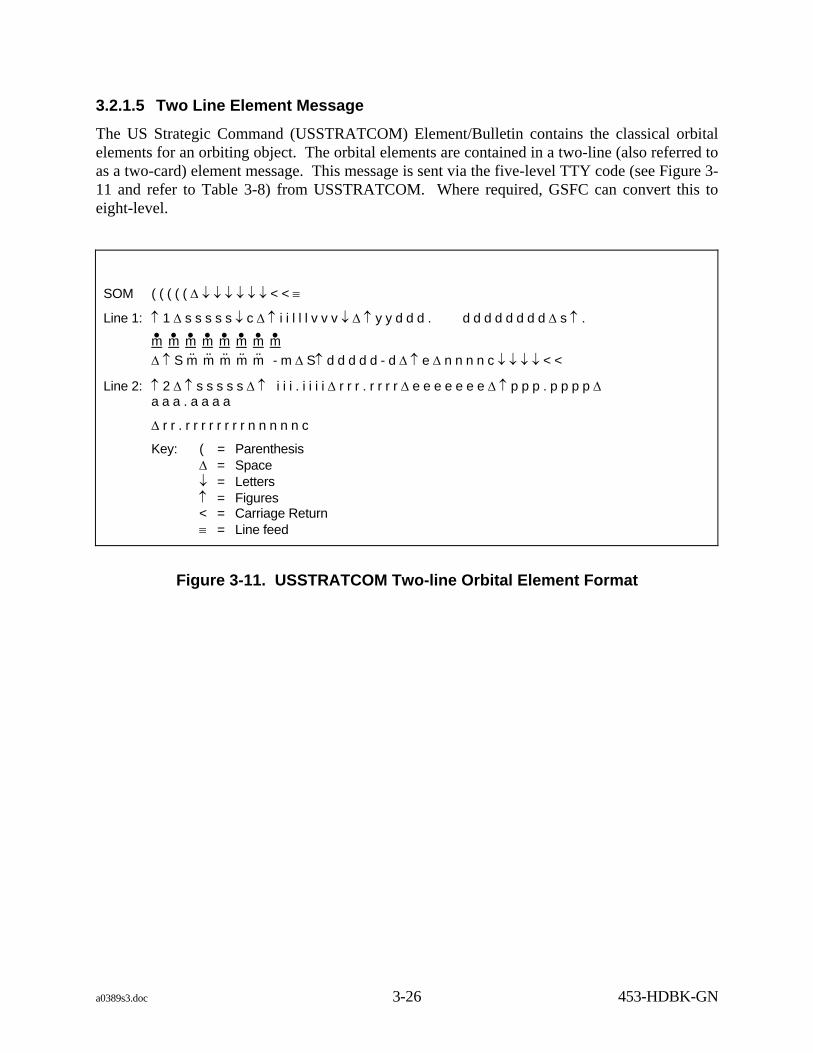
a0389s3.doc 3-26 453-HDBK-GN
3.2.1.5 Two Line Element Message
The US Strategic Command (USSTRATCOM) Element/Bulletin contains the classical orbital elements for an orbiting object. The orbital elements are contained in a two-line (also referred to as a two-card) element message. This message is sent via the five-level TTY code (see Figure 3-11 and refer to Table 3-8) from USSTRATCOM. Where required, GSFC can convert this to eight-level.
SOM ( ( ( ( ( ∆ ↓ ↓ ↓ ↓ ↓ ↓ < < ≡
Line 1: ↑ 1 ∆ s s s s s ↓ c ∆ ↑ i i l l l v v v ↓ ∆ ↑ y y d d d . d d d d d d d d ∆ s ↑ .
m• m• m• m• m• m• m• m• ∆ ↑ S m̈ m̈ m̈ m̈ m̈ - m ∆ S↑ d d d d d - d ∆ ↑ e ∆ n n n n c ↓ ↓ ↓ ↓ < <
Line 2: ↑ 2 ∆ ↑ s s s s s ∆ ↑ i i i . i i i i ∆ r r r . r r r r ∆ e e e e e e e ∆ ↑ p p p . p p p p ∆ a a a . a a a a
∆ r r . r r r r r r r r n n n n n c
Key: ( = Parenthesis ∆ = Space ↓ = Letters ↑ = Figures < = Carriage Return ≡ = Line feed
Figure 3-11. USSTRATCOM Two-line Orbital Element Format

a0389s3.doc 3-27 453-HDBK-GN
Table 3-8. Explanation of USSTRATCOM Two-line Orbital Element Format
Line Characters Explanation
SOM ((((( Fixed (start of message code) 1 sssss Satellite number c Classification
U = unclassified C = confidential S = secret
iilllvvv International Designator ii = launch year ill = launch number of year vvv = piece of launch
yy Epoch year of message ddd.dddddddd Epoch day and fraction of day S.mmmmmmmm First time derivative of the mean motion or ballistic coefficient (depending on
ephemeris type). Revolutions per day 2 or meters 2 per kilogram. S = minus sign if appropriate plus signs are not used.
S.mmmmm-m Second time derivative of mean motion. Revolutions per day 3. Decimal point assumed between S and first m. S = minus sign if applicable. This field will be blank if not applicable.
S.ddddd-d BSTAR drag term if GP4 general pertubations theory was used; otherwise, this field will be radiation pressure coefficient. S = minus sign if applicable.
e Ephemeris type: Specifies ephemeris theory used to produce the elements. 0 = mean inertial, 1 = osculating inertial.
nnnn Element number c Checksum: Modulo 10
2 sssss Satellite number. iii.iiii Inclination in degrees. rrr.rrrr Right ascension of ascending node in degrees. eeeeeee Eccentricity (decimal assumed at beginning of field). ppp.pppp Argument of perigee in degrees. aaa.aaaa Mean anomaly in degrees. rr.rrrrrrrr Mean motion (revolutions per day). nnnnn Revolution number at epoch. c Checksum: modulo 10.

a0389s3.doc 3-28 453-HDBK-GN
3.2.2 Acquisition Data Transmission
3.2.2.1 General
Acquisition data is transmitted by the FDF or JSC to GN ground stations via NISN. This data is generated in eight-level ASCII teletype format by FDF. The acquisition data is implanted into 4800-bit blocks by a Conversion Device (CD) and transmitted to the Tracking Data System (TDS) where it is converted to eight-level ASCII teletype format and sent to the tracking sites and range stations. Projects also send acquistion data via FTP and e-mail.
3.2.2.2 4800 Bit Block
Vectors are exchanged between NASA centers and external agencies. The vectors are formatted as IIRVs or EPVs and transmitted in 4800-bit blocks. The packing into blocks for IIRVs is illustrated in Figures 3-12 and 3-13; unique IIRV packing will be controlled by ICDs. The packing into blocks for EPVs is illustrated in Figures 3-14 and 3-15.

a0389s3.doc 3-29 453-HDBK-GN
Figure 3-12. Illustration of IIRV Data Words Packed into the Data Field of the 4800-bit Block Format
WORD 1
A0389007.DRW:X:N
BITLINE 1START LINE 1 WORD 2
WORD 15 START LINE 2
WORD 14WORD 13
WORD 16
END LINE 1
START LINE 3
WORD 46WORD 45
WORD 48
END LINE 2
WORD 47
START LINE 4
WORD 92
WORD 94
END LINE 3
WORD 93
START LINE 5
WORD 138
WORD 140
END LINE 4
WORD 139
START LINE 6
WORD 170
WORD 172
END LINE 5
WORD 171
WORD 184WORD 183 END LINE 6
REMAINING 394 WORDS OF THE4624-BIT DATA FIELD CONTAINSFILL (311 )8
1472 DATABITS (1BLOCKMESSAGE)
3152 FILLBITS
MSB1
LSB8
MSB1
LS

a0389s3.doc 3-30 453-HDBK-GN
Figure 3-13. Illustration of IIRV ASCII Characters Packed into the 4800-bit Block
A0389008.DRW:X:N
FIRST BIT TRANSMITTED(BIT 1, NASCOM HEADER)
1 8 1 8
4800-BIT BLOCKHEADER (144 BITS)
1 1 1 0 0 0 1 01 0 0 1 0 0 1 1
1 0 0 1 0 0 1 10 1 0 0 1 0 1 1
0 1 1 0 1 0 1 00 0 0 0 0 1 0 1
= I (WORD 2)
= R (WORD 4)
= SP (WORD 6)
(WORD 1) G =
(WORD 3) I =
(WORD 5) V =
1 0 1 0 1 1 0 0
WORD 15 INDICATES VECTORTYPE. IN THIS EXAMPLE IT ISA "5" INDICATING MANEUVER CUTOFF
DATA FIELD CONTAINS 4624 BITS
WORDS 185 THRU 578 WILL CONTAINFILL FOR A 1-BLOCK MESSAGE
32-BIT BLOCK ERROR CONTROL FIELD
16 BITS
EVEN PARITY ON BIT 8
(WORD 15) 5 =
(WORD 578)

a0389s3.doc 3-31 453-HDBK-GN
Figure 3-14. Illustration of EPV Data Words Packed Into the Data Field of the 4800-bit Block Format
WORD 1 BITLINE 1START LINE 1 WORD 2
WORD 17 START LINE 2
WORD 16WORD 15
WORD 18
END LINE 1
WORD 30WORD 29 START LINE 3
MSB1
LSB8
MSB1
LSB8
WORD 75 START LINE 4
WORD 74WORD 73
WORD 76
END LINE 3
WORD 135 END LINE 4 WORD 136
WORD 185 START LINE 6
WORD 184WORD 183
WORD 186
END LINE 5
WORD 235 END LINE 6 WORD 236
WORD 299 START LINE 8
WORD 298WORD 297
WORD 300
END LINE 7
WORD 357 START LINE 9
WORD 356WORD 355
WORD 358
END LINE 8
WORD 421 START LINE 10
WORD 420WORD 419
WORD 422
END LINE 9
WORD 485 START LINE 11
WORD 484WORD 483
WORD 486
END LINE 10
WORD 549 START LINE 12
WORD 548WORD 547
WORD 550
END LINE 11
WORD 561 END LINE 12
END LINE 2
START LINE 5
START LINE 7
REMAINING 13 WORDS OF THE 4592-BIT DATAFIELD CONTAIN FILL (311 )8 104 FILL BITS
4488 DATA BITS(1 BLOCKMESSAGE)
A0389009.DRW:X:N

a0389s3.doc 3-32 453-HDBK-GN
Figure 3-15. Illustration of EPV ASCII Characters Packed into the 4800-bit Block
A0389010.DRW:X:N
FIRST BIT TRANSMITTED(BIT 1, NASCOM HEADER)
1 8 1 8
4800-BIT BLOCKHEADER (144 BITS)
0 0 1 1 0 0 0 0 0 0 1 1 0 0 1 1 3 (WORD 2)
WORDS 1 AND 2INDICATE MESSAGETYPE. IN THISEXAMPLE, IT ISA "03"
(WORD 1) 0
0 1 0 0 0 1 1 1
DATA FIELD CONTAINS 4592 BITS
WORDS 562 THROUGH 574 WILL CONTAIN FILL
32-BIT BLOCK ERRORCONTROL FIELD
16 BITS
ZERO PARITY ON BIT 1
(WORD 17) G = (WORD 19) P =
(WORD 574)
= E (WORD 18)= V (WORD 20)0 1 0 1 0 0 0 0
0 1 0 0 0 1 0 1
0 1 0 1 0 1 1 0

a0389s3.doc 3-33 453-HDBK-GN
3.2.3 Acquisition Data Processing
GN sites use STPS, TTCP, and MPA for acquisition data processing. Reception of data is handled as follows (refer to the current tracking Software Support Instruction (SSI) for current version of operational software being used):
a. STPS.
1. The on-site STPS systems automatically receive and store acquisition data.
2. The STPS can accept Interrange Vector (IRV), Improved Interrange Vector (IIRV), and Internet Predict (INP) messages.
3. When the STPS is on, and the Update acq function is not being performed, the following apply:
(a) Any incoming acquisition message whose epoch or first-point time is more than 24 hours old from the current Universal Time Coordinated (UTC) will not be written to the disk. An operator message will list the acquisition message received but not saved.
(b) All disk-resident acquisition data whose epoch or first-point time is less than 24 hours old from current UTC is tagged for deletion and removed from the availability listing when new acquisition messages of the same type (IIRV, IRV, or INP) and identical Support Identification Code/Vehicle Identification Code (SIC/VID) and VS (CH) fields are received.
(c) All disk-resident acquisition data whose epoch or first-point time is less than 30 minutes (plus or minus) of the epoch or first-point time of the incoming acquisition data is tagged for deletion and removed from the availability listing by the incoming data, providing the SIC/VID and VS (CH) fields are identical.
(d) If the INP Time Check Override (ITOR) function is selected, all INPs regardless of epoch time or first-point are accepted and automatic purging is deactivated.
b. TTCP.
1. The TTCP can receive and hold one IIRV message, as follows:
(a) The TTCP determines the geometric validity of the message and writes the message to the disk.
(b) The existing message is deleted and replaced by the incoming message.
c. MPA. The MPA can accept IRV, IIRV, and INP messages.

a0389s3.doc 3-34 453-HDBK-GN
3.2.4 LTAS
High-speed acquisition data is utilized by some stations for launch and Shuttle landing support. The Launch Trajectory Acquisition System (LTAS) replaced the Launch Trajectory Data System (LTDS) in 1978.
Although originally adopted only as an acquisition data source for STDN, expanded support has mandated LTAS format for some tracking data requirements. Therefore, in that respect, it may be considered as dual function. The Central Computer Complex (CCC) can use almost any type of tracking data to generate LTAS, but the WLP Impact Prediction (IP) must have 2.4-kb/sec Minimum Delay Data Format (MDDF) data as an input. FDF, MIL, WPS, and the WLP radar can receive and process LTAS data. The 2.4-kb/sec LTAS data is transmitted Least Significant Bit (LSB) first and is composed of 240-bit blocks containing smoothed, best source, E, F, and G data. In addition, 16 of the 240 bits contain a pattern which allows the onstation processors at LTAS-equipped stations to synchronize on the incoming LTAS data and use it as an acquisition source. See Figure 3-16, and refer to Table 3-9 for an explanation of the format. The LTAS has three standard operational configurations as follows:
a. Cape Canaveral Launches. The CCC at Cape Canaveral receives real-time RADAR tracking data from the Eastern Test Range (ETR) and GN, and converts it to LTAS format for transmission to the WLP, and MIL tracking stations and to Flight Dynamics Facility (FDF).
b. Space Shuttle Landings.
1. Edwards AFB Landings. The CCC receives real-time radar tracking data from the WTR, Pacific Missile Test Center (PMTC), and Air Force Satellite Test Center (AFFTC), and converts it to LTAS format for transmission to the west coast tracking stations and to FDF.
2. Cape Kennedy Landings. ETR and WTR radars transmit real-time tracking data to CCC where it is converted to LTAS and transmitted to the MIL tracking station and to the FDF.
c. Ariane Launches. The WLP C-band transmits 2.4-kb/sec MDDF data to the IP system which converts it to LTAS format for transmission to GSFC and to Kourou, French Guiana. .

a0389s3.doc 3-35 453-HDBK-GN
Table 3-9. Explanation of Launch Trajectory Acquisition System 2400-b/sec Format* (1 of 3)
Bit No. Description 1-13 Satellite ID Code (binary) 14-17 Vehicle ID Code (binary) 18-26 Day of year (binary) 27-30 Format type (binary) = 0000 for LTAS 31-34 Time of Day - Tenths of seconds (binary - LSB = 0.1 sec) 35-51 Time of Day - Seconds (binary - LSB = 1.0 sec) 52-60 Site ID (refer to appendix C, table C-2) 61-87 E-position component (meters)
88 Sign for E (0 = positive) (1 = negative. When negative, bits 61-87 will be 2's complement.) 89-90 PSC (Position Scale Code: value by which all position components should be multiplied if the
field length is exceeded): 00 - x 1 01 - x 10 10 - x 103 11 - x 1010
91-117 F-position component (meters) 118 Sign for F (0 = positive) (1 = negative. When negative, bits 91-117 will be 2's complement.)

a0389s3.doc 3-36 453-HDBK-GN
Table 3-9. Explanation of Launch Trajectory Acquisition System 2400-b/sec Format* (2 of 3)
Bit No. Description 119-120 00 - x 1
01 - x 10 (All other scales are invalid)
*30 bits = 1 word; bit No. 1 = first bit transmitted. 121-147 G-position component (meters)
148 Sign for G (0 = positive) (1 = negative. When negative, bits 121-147 will be 2's complement.) 149 Optical Track Bit (OTB) (always = 0) 150 PTF (Plus Time Flag) (1 = using plus time)
151-164 F-velocity component (meters/second) 165 Sign for F 0 = positive (1 = negative. When negative, bits 151-164 will be 2's complement.)
166-179 E-velocity component (meters/second) 180 Sign for E 0 = positive (1 = negative. When negative, bits 166-179 will be 2's complement.) 181 L liftoff 1 = liftoff has occurred 182 P plunge mode 1 = plunge
183-184 P/W (Pulse Width) 00 - 1.0 µsec 01 - 2.4 µsec 10 - 5.0 µsec 11 - 10.0 µsec
185 RFI (Refraction correction) (0 = out)(1 = in) 186 DI (Droop) (0 = out) (1 = in) 187 PO (Paramp) (0 = off) (1 = on) 188 RO (Radiation) (0 = off) (1 = on) 189 LO (0 = Single LO) (1 = Dual LO) 190 B/S (Beacon/Skin) (0 = skin) (1 = beacon) 191 T (Track bit) (0 = off) (1 = on) 192 Q (Quality bit) (0 = bad) (1 = good)
NOTE When LTAS is generated by the BDA IP, bit 191 signifies the Angle bit (A) and bit 192 signifies the Range bit (R).
193-195 Mode (Bit No. 193 194 195) 0 0 0 = manual 1 0 0 = autotrack 0 1 0 = computer drive 1 1 0 = on-axis orbital 0 0 1 = on-axis powered flight 1 0 1 = on-axis coast 0 1 1 = autotrack coast
196-209 G-velocity component (meters/second)

a0389s3.doc 3-37 453-HDBK-GN
Table 3-9. Explanation of Launch Trajectory Acquisition System 2400-b/sec Format* (3 of 3)
Bit No. Description 210 Sign for G (0 = positive) (1 = negative. When negative bits 196-209 will be 2's complement.)
211-217 Checksum (see Note) 218-224 Spares. 225-240 Sync bits. Bits 225-240 will have the following patterns:
0-0-0-1-1-0-1-0-0-0-0-1-1-0-1- 0 on one message and 0-0-0-1-1-0-1-0-0-0-0-0-0-1-0-1 on the next.
NOTE LTAS 2400-b/sec checksum algorithm:
a. The first 210 data bits are treated as fourteen words of 15 bits each. These words are summed, treating them as positive integers, in an accumulator capable of handling a 19-bit positive integer sum.
b. This sum is split up into three parts: the most significant 7 bits, the next most significant 6 bits, and the least significant 6 bits, and these three words are summed, treating them as positive integers, in an accumulator capable of handling an 8-bit positive integer sum.
c. The least significant 7 bits of these sums become the checksum. *30 bits = 1 word; bit No. 1 = first bit transmitted.

a0389s3.doc 3-38 453-HDBK-GN
Figure 3-16. Launch Trajectory Acquisition System 2400-b/sec Data Format
A0389013.DRW:X:N
VID
14* 13* 12* 11* 10* 9* 8* 7* 6* 5* 4* 3* 2* *1 ** 15*
SIC (13 BITS)BIT NO.
FORMAT TYPE
29* 28* 27* 26* 25* 24* 23* 22* 21* 20* 19* 18* 17* 16** 30*
DAY OF YEARBIT NO. (4 BITS)
44* 43* 42* 41* 40* 39* 38* 37* 36* 35* 34* 33* 32* 31** 45*
TIME OF DAYBIT NO.
59* 58* 57* 56* 55* 54* 53* 52* 51* 50* 49* 48* 47** 60*
SITE IDENTIFICATIONBIT NO.
46*
74* 73* 72* 71* 70* 69* 68* 67* 66* 65* 64* 63* 62** 75*
E POSITION COMPONENT (METERS)BIT NO.
61*
89* 88* 87* 86* 85* 84* 83* 82* 81* 80* 79* 78* 77** 90*
PSCBIT NO.
76*
S
104* 103* 102* 101* 100* 99* 98* 97* 96* 95* 94* 93* 92** 105*
F POSITION COMPONENT (METERS)BIT NO.
91*
119* 118* 117* 116* 115* 114* 113* 112* 111* 110* 109* 108* 107** 120*
VSCBIT NO.
106*
S
134* 133* 132* 131* 130* 129* 128* 127* 126* 125* 124* 123* 122** 135*
G POSITION COMPONENT (METERS)BIT NO.
121*
149* 148* 147* 146* 145* 144* 143* 142* 141* 140* 139* 138* 137** 150*
BIT NO.
136*
PTF OTB S
164* 163* 162* 161* 160* 159* 158* 157* 156* 155* 154* 153* 152** 165*
F (METERS/SECOND)BIT NO.
151*
S
179* 178* 177* 176* 175* 174* 173* 172* 171* 170* 169* 168* 167** 180*
E (METERS/SECOND)BIT NO.
166*
S
194* 193* 192* 191* 190* 189* 188* 187* 186* 185* 184* 183* 182** 195*
MODEBIT NO.
181*
Q T B/S LO RO PO DI RI P/W P L
209* 208* 207* 206* 205* 204* 203 202* 201* 200* 199* 198* 197** 210*
G (METERS/SECOND)BIT NO.
196*
S
224* 223* 222* 221* 220* 219* 218* 217* 216* 215* 214* 213* 212** 225*
SPARESBIT NO.
211*
CHECKSUM
239* 238* 237* 236* 235* 234* 233 232* 231* 230* 229* 228* 227** 240*
SYNC BITSBIT NO.
226*
S
* * * * * * *

a0389s3.doc 3-39 453-HDBK-GN
3.3 Slaving Systems
3.3.1 Intrasite Slaving System
3.3.1.1 The Intrasite Slaving System (ISS), composed of slaving switch panels and a slaving junction box, provides a flexible method of slaving one onstation antenna to another. It allows any automatic-tracking type antenna to operate as a leader to drive one or more antennas without affecting the accuracy of the leader or introducing instabilities into the servo systems of either the leader or the slaved antennas.
3.3.1.2 Figure 3-17 illustrates the basic leader-to-slave configuration of the ISS. A slaving system synchro Control Transformer (CT) is mounted on each axis of those types of antennas which are slaves/leaders, and on each of the slave-only antennas. A slaving system synchro-transmitter (TX or CX) is also mounted on each axis of the automatic-tracking (leader) type antennas.
3.3.1.3 All leader and slave systems are interfaced through the slaving junction box. Each slave system also has a slaving switch panel to indicate the availability of leader-type angles. The slaving switch panel has indicators and controls for each of the interfaced systems. An indicator for the associated system will light on the leader system's slaving switch panel when the leader system is being used as a slave source. The upper portion of a split-screen Pushbutton Indicator (PBI) will light on the slave systems slaving switch panel for each leader system that is ready to be used as a slave source. To slave to the desired leader, press the split-screen PBI for the appropriate system. The lower portion of the split-screen PBI will light to indicate that the slave system is indeed slaved to the desired leader. The slaving capabilities of the GN stations with ISS are listed in Table 3-10.

a0389s3.doc 3-40 453-HDBK-GN
Table 3-10. ISS Slaving Capabilities
Station Antenna
AGO 12-m *
12-m TDPS*
9-m S-Band*
9-m STPS*
11-m RX/TX *
7-m L-Band RX
SATAN TX
7-m RX/TX
MIL 9-m S-band No. 1* 9-m S-band No. 2* TELTRAC, 18 element STPS 1 and 2*
WPS** STPS 1 and 2* S-band 7.3-m 1 and 2 Rx S-band 6-m TX 9-m S-band*
* These systems can be leaders in the slaving configuration. The others can only be followers. ** WLP indicates Wallops Island tracking radars, WPS indicates Wallops Island orbital tracking (TM/ranging).

a0389s3.doc 3-41/(3-42 blank) 453-HDBK-GN
Figure 3-17. Intrasite Slaving System Block Diagram
A0389018.DRW:X:N
X-Y DATA
SOURCE 3
SOURCE1, 2, OR 3
LEADER ANTENNACONSOLE
SOURCE 1
LEADER ANTENNA
Y-AXIS
X-AXIS TX CT
TX CTSLAVE ANTENNA
Y-AXIS
X-AXISTX CT
TX CT
SLAVING INDICATORPANEL
SLAVING SWITCHPANEL
SLAVE ANTENNACONSOLE
SLAVING SWITCHPANEL
LEADER ANTENNACONSOLE
SOURCE 2
LEADER ANTENNA
Y-AXIS
X-AXISTX CT
TX CT
SLAVING INDICATORPANEL
SLAVING SWITCHPANEL
SLAVING INDICATOR PANEL
TDPS
SLAVINGJUNCTION
BOX
SOURCE1, 2, OR 3

A0389s4.doc 4-1 453-HDBK-GN
Section 4. Tracking Data Formats and Reduction Algorithms
4.1 General This section describes the low- and high-speed tracking data formats transmitted by the GN stations and, where pertinent, from other networks. Applicable reduction algorithms are also given. Appendix E delineates the format applicable to each tracker with references to the paragraph numbers in this section.
4.2 Low-speed Tracking Data Formats
4.2.1 General
This paragraph describes the formats used for transmission of low-speed tracking data which is sent from the station via FTP (post-pass) or teletype circuits. Definitions of the various teletype code symbols are the same as those for acquisition data and are presented in Table 3-2.
Tracking data is sent in eight-level ASCII teletype format by tracking sites and range stations to the NISN Tracking Data System (TDS). The TDS implants the TTY-received tracking data into 4800-bit blocks. This tracking data is transmitted in that 4800-bit block format to a NISN Conversion Device (CD) for Internet Protocol/User Datagram Protocol (IP/UDP) encapsulation and transmission to the FDF or JSC.
4.2.2 Universal Tracking Data Format
4.2.2.1 Introduction
The Universal Tracking Data Format (UTDF) is used by all systems configured with a TDF, or else a STPS, ITCP, & MPA. The means of transmission is FTP (post-pass) from the TDF UTDF files and TRS systems may be via either a low-speed 110-baud TTY circuit or a high-speed 9.6-kb/sec circuit, depending on mission requirements. One sample of data contains 75 bytes and is the same for both low- and high-speed transmission. Table 4-1 describes the contents of a data sample, and Table 4-2 describes the system-unique modes required for bytes 49 and 50.
4.2.2.2 TTY Transmission
UTDF data transmitted via teletype from the TPS is at a sample rate of one sample per 10 seconds. When this Low-sample Rate (LSR) data is required by JSC or FDF, NISN packs the data into 4800-bit blocks for transmission. This procedure is discussed in paragraph 4.3.3.
4.2.2.3 FTP Transmission UTDF data transmitted post-pass via FTP is sent in files consisting of only the 75-byte UTDF frames. No larger block is used.

A0389s4.doc 4-2 453-HDBK-GN
Table 4-1. Universal Tracking Data Format (1 of 3)
Byte Format Description 1 0D(16) Fixed 2 0A(16) Fixed 3 01(16) Fixed 4 to 5 ASCII Tracking data router:
4141 = AA = GSFC 4444 = DD = GSFC 4646 = FF = GSFC/France (CNES) 4848 = HH = GSFC/Japan 4949 = II = GSFC/Germany (ESRO) 4A4A = JJ = GSFC/JSC
6 Binary Last two digits of current year 7 to 8 Binary SIC 9 to 10 Binary VID 11 to 14 Binary Seconds of year 15 to 18 Binary Microseconds of second 19 to 22 FOC Angle 1; X or az 23 to 26 FOC Angle 2; Y or el (Angle 2 byte/bit format is the same as for bytes 19-22.) NOTE For bytes 19-22/23-26, convert angle data to decimal form. Angle data is given in fractions of a circle. To express raw angle in degrees, multiply decimal angle by 8.381903173 x 10⁻⁸ (360 degrees divided by 232). When the STPS is initialized as WPS S08 or S37, these bytes will read zero. 27 to 32 Binary RTLT in 1/256 nsec (MSB = 524288 ns; LSB = 0.00390625 ns) 33 to 38 Binary Bias Doppler, counts of: 240 MHz + 1000 fd'
LSB = 1 count
39 to 40 Binary AGC (an integer:
−150 AGC8192 −50 = dBm )
Note: AGC field not used by systems with TDF 41 to 44 Binary Transmit frequency information in 10's of Hz 45 Discrete MSD = antenna size (xmit) as follows:
0(16) = less than 1 m 1(16) = 3.9 m 2(16) = 4.3 m 3(16) = 9 m 4(16) = 12 m 5(16) = 26 m 6(16) = TDRSS ground antenna 7(16) = 6 m 8(16) = 7.3 m 9(16) = 8.0 m A(16) through F(16) = spares

A0389s4.doc 4-3 453-HDBK-GN
Table 4-1. Universal Tracking Data Format (2 of 3) Byte Format Description 45
(cont) LSD = antenna geometry (xmit) as follows:
0(16) = az-el 1(16) = X-Y(+X-south) 2(16) = X-Y(+X-east) 3(16) = RA-DEC 4(16) = HR-DEC 5(16) through F(16) = spares
46 Binary Pad ID (xmit) Link ID (refer to Appendix C)
NOTE If S-band and 3 way, zeros are output. If S-band and 2 way, good data is output. If VHF and 3 way, zeros are output. If VHF and 2 way, byte 45 is 0 and 46 is pad ID. 47 Discrete Antenna size (rcv; refer to byte 45) 48 Binary Pad ID (rcv refer to byte 46)
NOTE If VHF, byte 47 is 0 and 48 is pad ID. If S-band, good data is output.
49-50 Discrete Mode-system unique (refer to Table 4-2) 51 Discrete Data validity by bit:
8 = (MSB) sidelobe (1 = sidelobe) 7 = destruct R
• (1 = destruct)
6 = refraction correction to R, R•
(1 = corrected) 5 = refraction correction to angles (1 = corrected) 4 = angle data correction (1 = corrected) 3 = angle valid (1 = valid) 2 = R
• valid (1 = valid)
1 = (LSB) R valid (1 = valid) 52 Discrete MSD= frequency band, as follows:
1(16) = VHF 2(16) = UHF 3(16) = S-band 4(16) = C-band 5(16) = X-band 6(16) = Ku-band 7(16) = visible 8(16) = S-band uplink/Ku-band downlink 9(16) through F(16) = spares

A0389s4.doc 4-4 453-HDBK-GN
Table 4-1. Universal Tracking Data Format (3 of 3)
Byte Format Description
52 (cont) Discrete LSD = data transmission type, as follows:
0(16) = test 1(16) = spare 2(16) = simulated 3(16) = resubmit 4(16) = RT (real time) 5(16) = PB (playback) 6(16) through F(16) = spares
53 to 54 Discrete MSD = tracker type:
Byte 53, bits 8 through 5:
0(16) = C-band pulse track 1(16) = SRE (S-band and VHF) or RER 2(16) = X-Y angles only (data acquisition antenna) 3(16) = Spare 4(16) = SGLS (AFSCF S-band trackers) 5(16) = Spare 6(16) = TDRSS 7(16) = STGT/WSGTU 8(16) = TDRSS TT&C 9(16) through F(16) = spares
Byte 53, bit 4:
1 = last frame of data (not used by systems with TDF)
Byte 53, bits 3 through 1 and eight bits of byte 54:
11 bits for transmission rate (positive indicates the binary seconds between samples up to a maximum of 1023; negative indicates the 2's complement of the number of samples per second).
55 to 72 Spare
73 04(16) Fixed.
74 0F(16) Fixed.
75 0F(16) Fixed.

A0389s4.doc 4-5 453-HDBK-GN
Table 4-2. System-unique Modes
System Bits Description C-band 1 (LSB) 0 = beacon, 1 = skin 2 0 4,3 00 = autotrack 01 = program track 10 = manual 11 = slaved 16 to 5 Rest spares
NOTE If for WPS S08 or S37, will always read slaved. If GRT S55 or S57, will always read slaved and angles valid bit will be set when in steptrack mode. SRE 1 (LSB) 0 = coherent 1 = noncoherent 2 0 = secondary, 1 = primary 4,3 See C-band 6,5 00 = not used 01 = 1-way 10 = 2-way 11 = 3-way 8,7 01 = lowest sidetone 10 Hz 10, 9 00 = not used
01 = major tone 20 kHz
10 = major tone 100 kHz 11 = major tone 500 kHz 13 to 11 Autotrack MFR, 1 to 6 (binary) (0 = unknown)
(MFR not applicable for TDF-equipped systems) 16 to 14 Range MFR, 1 to 4 (binary) (0 = unknown)
(MFR not applicable for TDF-equipped systems) SRE - VHF 2,1 Not used 4,3 See C-band 6,5 Not used 10,7 See SRE

A0389s4.doc 4-6 453-HDBK-GN
4.2.2.4 Data Reduction Algorithms
The following processes are used to convert UTDF to the decimal form of data, whether transmitted via FTP, TTY or 9.6-kb/sec circuits:
a. Observed Angles. To process, convert angle data to decimal form. To express angle data in degrees, multiply by 8.381903173 x 10⁻⁸.
NOTE
For X-Y angles only, subtract 360 degrees whenever the converted value exceeds 180 degrees.
b. Observed Range. The observed measurement is Round Trip Light Time (RTLT) in units of 1/256 nsec and is time-tagged at receive time. To process, convert range data to decimal form. In units of length, the range is R (T) = (c/512) 10-9 Rr (T)
where: c = speed of light in units of length/sec
Rr = raw range value in decimal form
c. Observed Range Rate. The Doppler measurement is the cumulative cycle count of the Doppler frequency plus a 240-MHz bias frequency. It is time tagged at the time of cycle counter reading. To process, convert Doppler data to decimal form. The observed average range rate is:
R• ( )T0 = -c
2fTKM ⎣⎢⎡
⎦⎥⎤N ( )T0 -N ( )T-1
T0 - T-1 -2.4 x 10⁸ (units, same as "c")
where: c = speed of light.
fT = transmit frequency in Hertz.
K = 240/221 for S-band, or 1 for VHF, 880/749 for X-band.
M = 1000 for S-band and VHF, 250 for X-band.
N = cumulative Doppler-plus-bias counter reading
T0, T-1 = time of present and previous Doppler count, respectively

A0389s4.doc 4-7 453-HDBK-GN
4.2.3 USSTRATCOM B3 Type 2 Radar Data Format
The USSTRATCOM B3 Type 2 data format consists of FPQ-6 radar data originating at WPS and transmitted to USSTRATCOM in real-time via NISN. The USSTRATCOM B3 Type 2 format is illustrated in Figure 4-1 and described in Table 4-3. (NASCOM TTY HEADER) BT (CR/CR/LF/LF) UNCLAS (CR/CR/LF/LF) ) ) U n n n i 2 t t t v v v v v d d d h h m m s s 0 0 0 x e e e e e e 0 a a a a a a a 0 r r r r r r r 2 0 c $ $
Figure 4-1. USSTRATCOM B3 Type 2 Radar Data Format

A0389s4.doc 4-8 453-HDBK-GN
Table 4-3. Explanation of USSTRATCOM B3 Type-2 Radar Data Format
Character Number
Character Explanation
BT CR/CR/LF/LF UNCLAS CR/CR/LF/LF
(Break) (2 carriage returns and 2 line feeds) Unclassified message (2 carriage returns and 2 line feeds)
1-2 )) Start of message (fixed) 3 U Unclassified (fixed)
4-6 nnn 000 to 999 = message number; assigned sequentially to observation messages by the reporting station
7 i Report indicator: 3 = First line 4 = Body line 5 = Last line 8 = Data off track
8 2 Observation type = AZ/EL/R (fixed) 9-11 ttt Station number:
439 = WLPS FPQ-6 12-16 vvvvv Satellite number; NORAD classification number.
17-28 dddhhmmss000 Time of observation: DDD = day of year HH = hour of day MM = minutes SS = seconds 000 = fractional part of seconds (fixed)
29-36 xeeeeee0 Elevation: X = sign
EEEEEE = elevation in degrees. Decimal point implied between second and third digits from left 0 = weight indicator (fixed)
37-44 aaaaaaa Azimuth: AAAAAAA = azimuth in degrees. Decimal point implied between third
and fourth digits from the left 0 = weight indicator (fixed)
45-53 rrrrrrr20 Range: RRRRRRR = range in kilometers. Decimal point implied between
the fourth and fifth digit from the left 2 = exponent (fixed at 2, indicates position of decimal point) 0 = weight indicator (fixed)
54 c Checksum; sum (Modulo 10) of characters 4 through 53 55-56 $$ End of message

A0389s4.doc 4-9 453-HDBK-GN
4.2.4 46-character Radar Data Format
4.2.4.1 General
The 46-character C-band format is illustrated in Figure 4-2 and described in Table 4-4. Each line of data is preceded by a line feed and two figure shifts or cancel codes and is followed by a carriage return. Each line is transmitted in the sequence indicated by the character (second column of Table 4-4). The azimuth, elevation, and range data are in octal form with the most significant character transmitted first. This data is transmitted to JSC for Shuttle support. It is packed into 4800-bit blocks at NISN prior to transmission, as illustrated in Figure 4-3.
RR↓< ≡ (start of message) ≡ ↑ ↑ v s s z d h h m m s s a a a a a a a e e e e e e e r r r r r r r r r d o y s i c c m < ≡ ↑ # ↓ (end of message) Key: ↓ = letter shift (5 level) or delete code (8 level) < = carriage return ≡ = line feed ↑ = figure shift (5 level) or cancel code (8 level) # = pound sign
Figure 4-2. C-band 46-character Radar Data Format

A0389s4.doc 4-10 453-HDBK-GN
Table 4-4. Explanation of Radar 46-character Format Number Characters Explanation (SOM) RR Low-speed data router
where: RR = DD for GSFC only = JJ for JSC and GSFC = KK for GRTS/JSC/ETR = II for GSFC/Germany
↓ Letter shift (5 level) or delete (8 level) < Carriage return ≡ Line feed ↓ Letter shift (5 level) or delete (8 level) 1 ≡ Line feed
2 to 3 -- Figure shifts (5 level) or cancel (8 level) 4 v Vehicle ID (0 to 9)
5 to 6 ss Station ID (refer to appendix C) 7 z RADAR ID (0 to 9) 8 d Data validity (0 = invalid/2 = valid) 9 h Time (UTC) hours (tens) 10 h hours (units) 11 m minutes (tens) 12 m minutes (units) 13 s seconds (tens) 14 s seconds (units)
15 to 21 aaaaaaa Azimuth angle where: 15 = (0 to 1) 16 to 21 = (0-7) LSB = 0.0006866455 deg
22 to 28 eeeeeee Elevation angle where: 22 = (0 to 1) 23 to 28 = (0 to 7) LSB = 0.0006866455 deg
29 to 37 rrrrrrrrr Range where: 29 = (0-1) 30 to 37 = (0-7) LSB = 1.7859375 meters
38 to 40 doy UTC day of year (000 to 366) 41 to 44 sicc Support ID code (0000 to 9999)
45 m Mode where: 1 = beacon 2 = skin 3 = test 4 = last frame
46 CR Carriage return (EOM) ≡ Line feed
↑ Figure shift (5 level) or cancel (8 level) # Pound sign ↓ Letter shift (5 level) or delete (8 level)

A0389s4.doc 4-11 453-HDBK-GN
Figure 4-3. Packing of 46-character C-band LSR Data

A0389s4.doc 4-12 453-HDBK-GN
4.2.4.2 DOD C-band Trackers
The DOD C-band trackers are capable of correcting data for tropospheric and ionospheric refraction upon request. The onstation refraction corrections are documented in STDN No. 601 (mission Network Operations Support Plan [NOSP]). STDN stations do not apply a refraction correction. Transponder delay is always applied onstation.
4.2.4.3 Data Reduction Algorithm
Appropriate conversions are noted in the format description.
4.3 High-speed Tracking Data Formats
4.3.1 General This paragraph describes the types of high-speed tracking data formats transmitted from the GN. LTAS, which is also used as a tracking data format, is described in paragraph 3.2.4. Refer to appendix E for station format transmission capabilities.
This data is sent in 240-bit blocks by launch-support tracking sites to the NISN TDS. The TDS implants the received high-speed tracking data into 4800-bit blocks. This tracking data is transmitted in that 4800-bit block format to a NISN CD for IP/UDP encapsulation and transmission to the FDF or JSC.
4.3.2 Minimum Delay Data Format
4.3.2.1 General
The MDDF transmit capability exists at WGS and MIL S-band and on the WGS radar. Each frame of data contains 240 bits. See Figure 4-4 for MDDF format, and refer to Table 4-5 for an explanation of the format.

A0389s4.doc 4-13 453-HDBK-GN
Figure 4-4. MDDF Format

A0389s4.doc 4-14 453-HDBK-GN
Table 4-5. Explanation of MDDF Format (1 of 2)
Bit Description
1-13 SIC (binary) 14-17 VID (binary) 18-26 Day of year (binary) 27-30 Format type (binary) 27
0 281
291
301
31-34 Time of day (binary-tenths of seconds) BITVALUE =
310.1
320.2
330.4
340.8
35-51 Time of day (binary-seconds) BITVALUE =
351
362
5165536
52-60 Site ID (Refer to Appendix C, Table C-2) NOTE
To decode the angle fields (bits 61-79/80-98), convert to decimal and multiply by the granularity (0.0006866455 degree). If the result is between 180 and 360 degrees, the angle is negative (except for the azimuth reading on az-el trackers) and can be determined by subtracting 360 degrees from the result.
61-79 Angle 1 (X or azimuth) (LSB = 0.0006866455) (binary) 80-98 Angle 2 (Y or elevation) (LSB = 0.0006866455) (binary) 99-123 Range (LSB = 1.7859375 m) (binary) 124-171 Doppler (counts of 240 MHz + 1000 fd) (LSB = 1 cycle)* 172-173 One-, two-, or three-way data:
172 173 0 0 = 1-way 1 0 = 2-way 1 1 = 3-way
174 R/T (real/test) 1 = real data
175-176 Geo (antenna geometry): 175 176
0 0 = az-el 1 0 = (X-Y) (+X = south) 1 1 = (X-Y) (+X = east)
177-180 Toggle bits: 177 178 179 180 On one frame: 1 0 1 1
On next frame: 0 1 0 0 181 L (liftoff); 1 = liftoff has occurred 182 P (plunge mode); 1 = plunge 183-184 P/W (Pulse width): 183 184
0 0 = 1.0 m sec 1 0 = 2.4 m sec 0 1 = 5.0 m sec (0.25 sec for WFC radars) 1 1 = 10.0 m sec (0.5 sec for WFC radars)
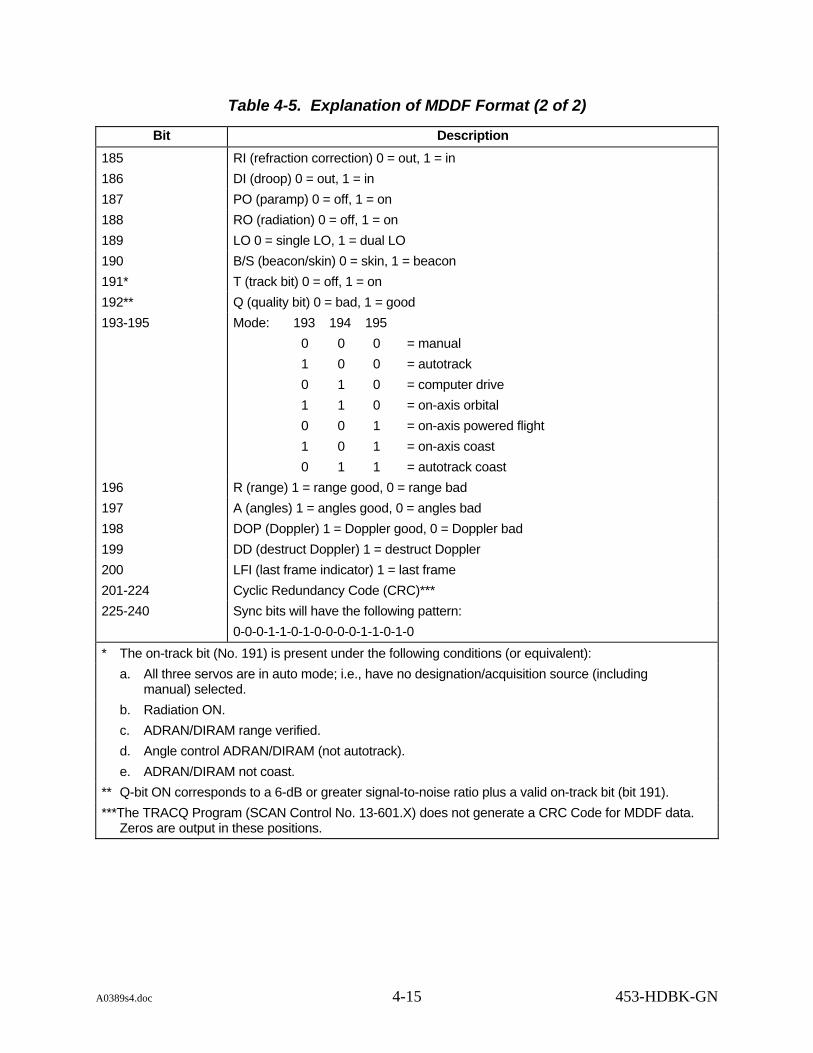
A0389s4.doc 4-15 453-HDBK-GN
Table 4-5. Explanation of MDDF Format (2 of 2)
Bit Description 185 RI (refraction correction) 0 = out, 1 = in 186 DI (droop) 0 = out, 1 = in 187 PO (paramp) 0 = off, 1 = on 188 RO (radiation) 0 = off, 1 = on 189 LO 0 = single LO, 1 = dual LO 190 B/S (beacon/skin) 0 = skin, 1 = beacon 191* T (track bit) 0 = off, 1 = on 192** Q (quality bit) 0 = bad, 1 = good 193-195 Mode: 193 194 195
0 0 0 = manual 1 0 0 = autotrack 0 1 0 = computer drive 1 1 0 = on-axis orbital 0 0 1 = on-axis powered flight 1 0 1 = on-axis coast 0 1 1 = autotrack coast
196 R (range) 1 = range good, 0 = range bad 197 A (angles) 1 = angles good, 0 = angles bad 198 DOP (Doppler) 1 = Doppler good, 0 = Doppler bad 199 DD (destruct Doppler) 1 = destruct Doppler 200 LFI (last frame indicator) 1 = last frame 201-224 Cyclic Redundancy Code (CRC)*** 225-240 Sync bits will have the following pattern:
0-0-0-1-1-0-1-0-0-0-0-1-1-0-1-0 * The on-track bit (No. 191) is present under the following conditions (or equivalent):
a. All three servos are in auto mode; i.e., have no designation/acquisition source (including manual) selected. b. Radiation ON. c. ADRAN/DIRAM range verified. d. Angle control ADRAN/DIRAM (not autotrack). e. ADRAN/DIRAM not coast.
** Q-bit ON corresponds to a 6-dB or greater signal-to-noise ratio plus a valid on-track bit (bit 191). ***The TRACQ Program (SCAN Control No. 13-601.X) does not generate a CRC Code for MDDF data.
Zeros are output in these positions.

A0389s4.doc 4-16 453-HDBK-GN
4.3.2.2 Cyclic Redundancy Code
a. A Cyclic Redundancy Code (CRC), formerly called a polynomial error code, is used to protect the data in the MDDF. The data that is to be protected is used to create a polynomial D(X), which is then divided by a known polynomial G(X) of degree 22. The remainder polynomial from this division is then used to determine the 22-bit CRC.
b. The polynomials used have coefficients in F2, the field with two elements. The following truth tables summarize the necessary facts about F2:
Addition Table
0 1
0 0 1
1 1 0
Multiplication Table
0 1
0 0 0
1 0 1
F2 = 0,1
For example; F(X) = X2 + X + 1 and G(X) = X2 + 1 are two polynomials with coefficients in F2. Performing the indicated operations on the coefficients in F2, the following is found:
F(X) + G(X) = X and F(X); G(X) = X4 + X3 + X + 1
c. As a simple example of CRCs, consider a data block of eight bits to have three-bit CRC, and generating the polynomial G(X) = X3 + X + 1. Suppose the following eight-bit serial data stream was to be sent:
+-------------- 10011110 ¦ +------- First bit transmitted
d. Generate D(X) = X10 + X7 + X6+ X5 + X4, where the coefficients are the data bits in transmitted order, and the leading power of X is 8 + 3 - 1 = 10. Doing the division, the following is found:
X10 + X7 + X6 + X5 + X4 = (X7 + X5 + X) (X3 + X + 1) + (X2+ X).
R(X) = X2 + X and the CRC is 110 (the coefficients).
e. The eleven bits transmitted are:
10011110 110 Data) (CRC) First bit sent

A0389s4.doc 4-17 453-HDBK-GN
f. Computer implementation of this division is as follows:
1. Append three zeros to the data to get the correct polynomial: 10011110000.
2. From left to right, exclusive OR the 4-bit pattern for G(X) at each successive 1:
10011110000 1011 101110000 1011 10000 1011 110
Since an LSB transmit of the data is used, a small change in the algorithm is necessary.
3. By bit flipping the pattern for G(X), D(X) and working right to left, the correct CRC is generated in a form that is directly transmitted as follows:
00001111001 1101 000011101 1101 00001 1101 011
with a transmitted CRC of 110 (transmitting LSB first).
g. Bits 201 through 224 are the CRC in the MDDF. A 22-bit CRC is used, and the two additional bits are flags that could be used by intervening hardware decoders to indicate that the CRC did not check. Initially, they are zeros.
4.3.3 High-speed Universal Tracking Data Format
4.3.3.1 General
High Sample Rate (HSR) tracking data is available from GN trackers. The means of transmission is either FTP (post-pass) or a high-speed 9.6-kb/sec circuit. Its transmission by NISN utilizes the 4800-bit block structure shown in Figure 4-5 and defined in Table 4-6. Each block is segmented into five distinct fields as shown in Figure 4-5. These fields contain the following:
a. Network Control Header, Bytes 1 through 6. Used to identify the start and type of message of each 4800-bit data block.
b. User Header, Bytes 7 through 12. Contains the information required by the user to route and process the data contained in the block. Note that bits 65-72 (refer to Table 4-6) define the type of tracker and the type of UTDF (LSR or HSR) data.
c. Time Field, Bytes 13 through 18. This field is set to logical ones in TDRS data. This is an optional NASA entry-binary time code (reception time of first bit in the data field bit 145).

A0389s4.doc 4-18 453-HDBK-GN
Figure 4-5. 4800-bit Data Block Structure

A0389s4.doc 4-19 453-HDBK-GN
Table 4-6. 4800-bit Block Structure, Tracking Data (1 of 2)
Bit Number Description Network Header
1 to 24 Synchronizaton: A bit pattern identifying beginning of block sync pattern = 011 000 100 111 011 000 100 111 (30473047 octal) (627627 hex)
25 to 32 Source: Geographic source of the data (note) 33 to 40 Destination: Geographic destination of the data (note) 41 to 43 Block Sequence Number: Identifies the sequence in which the source transmits the
block. Set to 0 in DSN format. 44 to 47 Format Code: Identifies general type of data
C-band = 0110 TDPS = 1110 tracking data TDRSS = 0101 TDPS UPDATE DATA = 0001
48 Block Size: 1 = 4800 bit block/0 = 1200 bit block User Header
NOTE 1. This header field varies depending on user requirements. Two user headers will be detailed; the user header transmitted by STDN and the user header transmitted by TDRSS. 2. Refer to Digital Data Source/Destination and Format Code Handbook for the NISN Nascom Message Switching System, GSFC-NISN-COM-99-001 , or NASA Communications Operating Procedures, Volume 1, 452-006 for these codes. NISN controls these documents.
STDN User Header 49 to 56 Source Circuit ID: Identifies, by circuit, the geographic source of the data (refer to
Table 4-7). If a DSN rate of 1 sample/sec, 1/10 sec, or 1/60 sec is selected, this field is overwritten with 001 octal.
57 to 60 Source Circuit Sequence No. Sequence number assigned on a circuit basis. 61 Spare 62 to 64 Block Sequence No. Same information as Block Sequence No. in the Network Header.
This number is repeated here because the Network Header Block Sequence Number will be overwritten when the data is retransmitted from GSFC to JSC. Set to 0 when DSN sample rate is used.
65 to 72 Message Type: 251 octal = S-band HSR tracking data. (A9 hex) 106 octal = MDDF tracking data (46 hex) 211 octal = S-band LSR tracking data. (89 hex) 367 octal = S-band LSR (TTY) tracking data (F7 hex) 370 octal = C-band 46 character tracking data. (F8 hex) 360 octal = TDRSS user and TT&C tracking data (hex F0)
73 to 80 Destination: Geographic destination of the block. Same as destination in Network Header. 81 and 82 Spares 83 Full Block Flag: Set = 0 if fill pattern contained in the data field. Fill pattern = 311 octal. 84 to 96 Data Length: Binary count of number of actual data bits in the block. Fill bits not included. When using
STDN rate of 10:1 or DSN rate of 1:1, this should be 4200. When using DSN rate of 1:10 or 1:60, it should be 600.

A0389s4.doc 4-20 453-HDBK-GN
Table 4-6. 4800-bit Block Structure, Tracking Data (2 of 2)
Bit Number Description TDRSS User Header
49 to 52 Block Sequence No.: Block sequence number within a message 53 to 64 Message Identity: 4095 65 to 71 Fixed at 0001111 72 to 75 Message Type. Fixed at 0001 76 to 80 Protocol Control Flags 81 and 82 Spares 83 Full Block Flag. (No fill data.) 84 to 96 Message Field Size: The number of data bits in the data field, excluding fill data (600 for
sample rates of 1/10 sec and 1/60 sec, and 4200 for sample rates of 1/10 sec and 1/sec) Time Field
97 to 144 TDRSS Data: Time field set to logical ones STDN/NASA: This is an optional binary time code that indicates the time of reception of the
first data bits (bit 145). DSN: Tracking Data Processor System (TDPS) tracking data transmitted to JPL contains a
time tag in a modified PB4 format: NOTE
In the Parallel Binary Time format, PB1 is to milliseconds resolution and PB4 to microseconds. The modified PB4 format merely sets all microsecond bits to zero, in effect changing the PB4 value to the PB1 resolution.
97 to 98 Parity, set to zero. 99 to 107 Day of year, binary. 108 to 134 Milliseconds of day. 135 to 144 Microseconds, set to zero.
NOTE UTDF sample rate selection determines the contents of this field. A rate of 10:1 sec sets field to zeros. Other rates insert the PB4 format.
Data Field
145 to 4768 Tracking Data. From 1 to 7 UTDF frames of data at a 10/sec, 1/sec, 1/10 sec, or 1/60 sec sample rate. If less than 7 frames of data in the data field then a FILL data pattern (311 octal) will be inserted following the data. Bits 4345 through 4400 and Bits 4641 through 4768 will always contain fill data. Bits 4401 through 4640 will contain Tracking Residuals and Time if HSR data, and transmitting station is GDS, RID, or NBE, and sample rate is other than 10/sec; if sample rate is 10/sec then these bits will contain fill data also. (The data field is transmitted sequentially in 8-bit with the most significant byte transmitted first. STDN transmits the LSB of each byte first, while TDRSS transmits the MSB of each byte first. See Figure 4-7 for layout of packing of HSR data.)
Block Error Control. This field set to 1's for TDRSS 4769 to 4776 STDN. Spare. 4777 STDN Polynomial Status Flag. Indicates the polynomial check passed/failed at GSFC. 4778 STDN Polynomial Status Flag. Indicates the polynomial check passed/failed at JSC. 4779 to 4800 Polynomial Reminder. This results from encoding the block at the source.

A0389s4.doc 4-21 453-HDBK-GN
d. Data Field, Bytes 19 through 596, GSTDN/JPL. The data field contains from one to seven tracking data samples (refer to Table 4-1 for description of a sample). If the 9.6 kb/sec circuits are being utilized for transmission of LSR data (refer to paragraph 4.2.2), the sample rate will be 1/10 sec. If HSR data is being transmitted, the sample rate may be 10/sec, 1/sec, 1/10 sec, or 1/60 sec. The portion of the data field between the end of the last tracking data sample and the first bit of the error control field is filled by a fixed pattern of 311 octal.
e. Data Field, Bytes 550 through 579, JPL/DSN 26-m Subnet Only. If HSR data and sample rate is 1/sec, 1/10 sec, or 1/60 sec, these bytes contain Tracking Data Residuals (O-Cs) and Time. If sample rate is 10/sec, these bytes will contain fill data (octal 311).
f. Error Control Field, Bytes 597 through 600. This field is set to logical ones for TDRSS data. NASA uses this field to determine whether bit errors occurred during the transmission of the block.
4.3.3.2 Construction of 4800-bit Block
Regardless of whether UTDF is LSR (refer to paragraph 4.2.2) or HSR (refer to paragraph 4.3.3), when transmitted on 9.6-kb/sec circuits, it is first packed into 4800-bit blocks. Each data sample (shown in Figure 4-6) is packed into a data field as shown in Figure 4-7. This data field will contain up to 7 samples of 75 bytes each, plus fill, plus tracking residuals (JPL only), and when complete, will become that portion of the block labeled DATA in Figure 4-5. The remainder of the block structure is as outlined in the preceding paragraph. The 4800 bit block is transmitted sequentially in 8-bit with the MSB of each byte first, except for the synchronization bits and the source circuit ID bits. TDRSS transmits the MSB of each byte first. See Figure 4-7 for a layout of the packing of the HSR data.
4.3.3.3 Data Reduction
UTDF transmitted on the 9.6-kb/sec lines is converted to decimal form in the same manner as teletype transmission. The algorithms used in this process are discussed in paragraph 4.2.2.4.

A0389s4.doc 4-22 453-HDBK-GN
Figure 4-6. Packing of LSR Data Sample (Universal Format)

A0389s4.doc 4-23 453-HDBK-GN
Figure 4-7. Packing of HSR Data Field (Universal Format)

A0389s4.doc 4-24 453-HDBK-GN
Table 4-7. Source Circuit ID Codes (Octal)
GN Site Line 1 Line 2 Line 3 9.6 kb/sec Track
SPARE 030 031 032 NA AGO 040 041 042 NA SPARE 064 065 066 067 MIL 004 005 006 007 PDL 110 NA NA NA SOCC 134 135 136 NA VANS NA NA NA 151 WSSH 220 NA NA NA SPARE 153 154 NA NA GSFC Interfaces TTY/4.8 (Track) 377 FDF 377 NCC 377 POCC 377
NOTE For GSFC interfaces with source circuit codes of 377, the source circuit sequence number will always contain all ones.

A0389s5.doc 5-1 453-HDBK-GN
Section 5. Computer Program Applications
5.1 General This section gives a general description of the onstation computer programs which process acquisition data (described in Section 3) and transmit tracking data (described in Section 4).
5.2 Tracking and Acquisition Programs
5.2.1 S-band Tracking Processor System
5.2.1.1 The STPS has been designed as a real-time control system and a data processing system for the NASA antenna systems in the GN. The heart of the system consists of two Central Processor Unit (CPU) cards located in a Multibus chassis which are programmed to accomplish the necessary control and data handling functions in real time. The STPS processes acquisition data, controls and monitors the S-band antenna, and records, formats, and transmits tracking data. The STPS interfaces with various antenna systems, the Antenna Control Console (ACC), the Multi-function Receivers (MFR), the Ranging Equipment (RE), the station timing system, and station communications equipment. See Figure 5-1 for a typical STPS configuration. The STPS has three functions. First, it monitors the antenna through incoming data from the Interface to the Antenna Control Console (IACC). Second, the system assists in acquiring and tracking a spacecraft by use of IRV, IIRV, INP, MDDF and LTAS data. The system maintains a data base on disk of IRVs, IIRVs and INPs and integrates and interpolates the respective data to predict the position of a spacecraft. The STPS can then position the antenna to the predicted position through the IACC. Third, the STPS transmits tracking data for a spacecraft over 9.6 kb/sec, 2.4 kb/sec, and TTY data lines.
5.2.1.2 The STPS operational software provides the following functions via two modes of operation, Online and Offline. The Online mode provides all functions required to perform a real time support and perform look angle generation. The Offline mode is used to perform functions which require a full text display at the operators terminal such as site-unique and support-unique files editing and manipulation, playback and resubmit operations, slew tests, and look angle generation when outputting to the Cathod Ray Tube (CRT). All functions available in the Online mode are also available in the Offline mode.
a. Data acquisition from the antenna and range equipment via the IACC.
b. Output antenna drive signals.

A0389s5.doc 5-2 453-HDBK-GN
Figure 5-1. Typical USB TPS Configuration

A0389s5.doc 5-3 453-HDBK-GN
c. Format, output, and log tracking data.
d. Generate spacecraft position predict data.
e. Update CRT display.
f. Drive digital to synchro bus.
g. Receive, store, and retrieve system disk-resident acquisition data.
h. Look angle generation.
i. Playbacks.
j. Log tape delogs.
k. Acquisition data file management.
l. Site file updata and display.
5.2.2 Metric Pointing Assembly
The Metric Pointing Assembly (MPA) is part of the Deep Space Communications Complex (DSCC) Tracking Subsystem (DTK). The MPA performs the tracking and antenna pointing functions for the GN antennas. The MPA consists of two Modcomp 9735 computers, the MPA Controller (MPC) and the MPA Realtime Computer (MPR). The MPC performs the monitor and control functions (directives, displays, etc.). The MPC is also used for local control. The MPR performs the realtime functions (device control, data type generation, etc.) and is connected to the servo subsystem and Receiver Exciter Ranging (RER) equipment. The MPR also receives LTAS data and sends MDDF data to non-DSN users.
5.2.3 Tracking, Telemetry, and Command Processor
5.2.3.1 The TTCP has been designed as a real-time control system and a data processing system for the 4.6 and 10-m antenna systems located at the RGRT station in Canberra. The heart of the system consists of a 80386DX Personal Computer (PC) which is programmed to accomplish the necessary control and data handling functions in real time. The TTCP processes acquisition data, controls and monitors the 10-m S-band antenna and the 4.6-m ku-band antenna, formats and transmits lowspeed UTDF tracking data, and receives control from and sends status to the OMCS. The TTCP interfaces with the antenna systems, the MFR, the RE, the exciter, the station timing system, station communications equipment, and the OMCS. See Figure ____ for a typical TTCP configuration. The TTCP has three functions. First, it monitors the antennas through incoming asynchronous data from the antenna controllers. Second, the system assists in acquiring and tracking a spacecraft by use of IIRV data. The system maintains on disk one IIRV and processes the data to predict the position of the TDRS F1 spacecraft. The TTCP can then position the antenna to the predicted position through the respective antenna controllers. Third, the TTCP transmits tracking data for the TDRS F1 spacecraft over TTY data lines.
5.2.3.2 The TTCP operational software has two modes of operation, Local and Remote. The Local mode
A0389s5.doc 5-4 453-HDBK-GN
allows all functions required to perform a real-time support to be operated from the TTCP. The Remote mode allows all functions required to perform a real-time support to be operated from the OMCS. An IIRV can be entered from the front panel when in Remote mode, but none of the other functions can be used locally. When in Local mode, status is sent to the OMCS, but commands are ignored. The TTCP provides the following:
a. Data acquisition from the antenna and range equipment.
b. Output antenna drive signals.
c. Format and output lowspeed UTDF tracking data.
d. Generate spacecraft position predict data.
e. Update CRT display.
f. Receive, store, and retrieve one disk-resident IIRV acquisition data message.
g. Antenna parameters file update and display.
5.3 Data Correction System Applicability
5.3.1 TPS S-band (Angle Data Correction)
The TPS software contains algorithms to correct tracking data angles for mount misalignment and other system errors. The following equations are used:
a. X = A1- A2 sin X sec Y + A3 tan Y - A4 sec Y + A5 tan Y sin X - A6 tan Y cos X
b. Y = A7 - A8 cos X sin Y + A5 cos X + A6 sin X
where: ∆X = X-angle correction to be subtracted from X-angle observations ∆Y = Y-angle correction to be subtracted from Y-angle observations
X = X-angle value. Y = Y-angle value.
A1 = X-angle encoder bias less tilt (eastward for 9-meter, southward for 26-meter antenna configurations) of upward normal to plane or base of antenna. This coefficient is also referred to as X-angle encoder bias.
A2 = elevation deflection associated with X-direction (structural sag minus feed droop). This coefficient is also referred to as X-angle structural deflection.
A3 = Y-axis to X-axis lack of orthogonality. A4 = RF-axis to Y-axis lack of orthogonality. This coefficient is also referred
to as RF-axis misalignment. A5 = tilt of end of X-axis upward (north end for 9-meter, east end for 26-meter
antenna configurations).

A0389s5.doc 5-5 453-HDBK-GN
A6 = tilt of end (north end for 9-meter, east end for 26-meter antenna configura-tions) of X-axis (eastward for 9-meter, southward for 26-meter antenna configurations). This coefficient is also referred to as rotation.
A7 = Y-angle encoder bias less RF-axis to X-axis lack of orthogonality. This coefficient is also referred to as Y-angle encoder bias.
A8 = elevation deflection associated with Y-direction (structural sag minus feed droop). This coefficient is also referred to as Y-angle structural deflection.
5.3.2 RTPS Computer System
The RTPS program provides the following corrections to the FPQ-6 raw data:
a. Azimuth and elevation servo lag corrections, if selected, are computed in track mode and whenever AGC data is available. The corrections are computed and stored in cells ATC and ETC, respectively, using equations:
1. ATC = COA0/ + VA • VRVA
2. ETC = COB0/ + VE • VRVE
where: VA, VE = azimuth and elevation servo error voltages COA0/ , COB0/ = nonvariable linear-fit coefficients of azimuth and
elevation lag VRVA, VRVE = azimuth and elevation lag linear-fit coefficients which
are tabular functions of AGC
NOTE
These optional dynamic corrections subsequently are added into cells ATT and ETT, respectively, which hold running sums of the dynamic and static error corrections as they are applied.
b. The first static error correction is for null shift. The null shift correction compensates for RF axis shift, which is a function of receiver frequency. Null shifts are combined with the lag corrections into cells ATT and ETT. At present, these cells contain 0's; therefore, the null shift correction has no effect on the input data.
c. Next the program corrects for elevation encoder nonlinearity resulting from encoder bias and eccentricity. The correction is computed and added to cell ETT with the equation:
ETT = ETT + ES + EBIAS + ELINB + K7sin(ES + EBIAS + EPHAZ)
where: ES = Raw elevation encoder value EBIAS = Elevation encoder bias K7 = Elevation encoder nonlinearity amplitude EPHAZ = Phase angle between elevation position and elevation linearity

A0389s5.doc 5-6 453-HDBK-GN
ELINB = Elevation linearity position bias
d. Elevation is then corrected for antenna droop with the equation:
ETT = ETT + K0 cos ETT
where: K0 = Antenna droop angle at 0 degrees elevation.
e. From the corrected elevation angle computed above, the program performs a secant correction to computer azimuth error. Then it corrects for azimuth encoder nonlinearity and for nonorthogonality relative to the elevation axis. The three equations used for these corrections are:
1. ATT = ATT 1
cos ETT
2. ATT = ATT + AS + ABIAS + ALINB + K6sin(AS + ABIAS + APHAZ)
3. ATT = ATT + K1tanETT
where: AS = Raw azimuth encoder value ABIAS = Azimuth encoder bias K6 = Azimuth encoder nonlinearity amplitude APHAZ = Phase angle between azimuth position and azimuth linearity K1 = Angle between the true Z axis and the Z axis of the radar
where, looking in the direction of 0 degrees azimuth, positive direction is to the right
ALINB = Azimuth linearity position bias

A0389s5.doc 5-7/(5-8 blank) 453-HDBK-GN
f. Finally, azimuth and elevation are corrected for pedestal misalignment, or leveling error, with the equations:
1. ATT = ATT + K2sin(ATT + K3)tanETT
2. ETT = ETT + K2cos(ATT + K3)
where: K2 represents the expression P2 + R2 K3 represents the expression tan -1R/P
and where: P = pedestal pitch at 0 degrees azimuth R = pedestal roll at 0 degrees azimuth
g. After all corrections are made, the corrected azimuth and elevation are loaded into cells AZ and EL for program use.
5.4 Masking The acquisition and tracking programs contain limits beyond which the antenna may not move. These limits are categorized as follows:
a. Hardware Limits. These are limits imposed by the mechanical design of the antenna. If these limits were to be exceeded, the antenna would crash into itself. The antenna servo system automatically turns off when this limit is reached.
b. Terrain Limits. Terrain limits are imposed by the contour of the nearby terrain. If these limits were to be exceeded, the antenna would be attempting to track through hills and mountains.
c. Restricted Zone Limits. The radiation into certain areas might interfere with private life in these areas.
5.5 System Applicability The TDPS computer program contain masking which takes all three types of limiting into consideration. Radiation restrictions may be fulfilled by adjustment of mechanical limit switches.

A0389s6.doc 6-1 453-HDBK-GN
Section 6. Magnetic Tape Record Formats and Usage
6.1 Introduction The tape formats described are intended to be applicable for the various systems currently being developed. An identical drive is being used on the STPS and RTPS systems. The model F880 Cipher drive and the Ciprico Tapemaster A multibus controller were chosen for the systems. The Cipher drive supports 100/50/25 IPS and 3200/1600 BPI. The Cipher drive has a high density for the application. This switch, in combination with the speed select bit in the Tapemaster setup, defines the speed/density used. The software for the application selects the lower speed. Table 6-1 defines the possible combinations.
Table 6-1. Speed and Density Combinations
Speed (IPS) Density High (3200) Low (1600)
Low 25 25 High 50 100
6.2 Tape Block Formats and Tape Operation
6.2.1 The application software currently defines five different tape block types (refer to Appendix F). To simplify controller driver software, all block types are the same size. The current block size is 32000 bytes. If all bytes are not used, the block is padded to the full block size.
6.2.2 Support for multiple logging sessions is provided by writing one filemark at the end of the logging session.
6.2.3 Any data that may not always be valid is provided with a status bit to flag whether or not it is currently valid in the block. All other data is always updated for each block.
6.3 Tape Block Types
6.3.1 Tape Block Type 1: Dynamic System Status Tape (RTPS or STPS)
Tape block type 1 is used to record data that is changing on a regular basis, such as stream data. This block is different from the rest of the other block types in one case. The size of this block is 1200 bytes versus 12000. This is to allow 10 samples of data per second. However, ten blocks are collected and written to tape as if they were a single block. Space is available in this block to support unique raw data for the different systems. Refer to paragraph F.1 of Appendix F.

A0389s6.doc 6-2 453-HDBK-GN
6.3.2 Tape Block Type 2 (RTPS or STPS)
Tape block type 2 is mainly used to log input and output acquisition messages. This block would normally be written to the tape when new data is available. Refer to paragraph F.2 of Appendix F.
6.3.3 Tape Block Type 3 (RTPS or STPS)
Tape block type 3 is used to log less common acquisition data messages. These include Brouwer, EPV, and digital synchro messages. At this time, block type 3 is used in the STPS system only. This block would normally be written to tape when new data is available. Refer to paragraph F.3 of Appendix F.
6.3.4 Tape Block Type 4 (RTPS)
Tape block type 4 is used to record ASCII-based system configuration and control messages provided by the Work Station. This block is used currently by the RTPS only. This block would normally be written to the tape when new data is available. Refer to paragraph F.4 of Appendix F.
6.3.5 Tape Block Type 5 (STPS)
Tape block type 5 is used to log raw UTDF Nascom blocks. This block is currently only used on the STPS system. This block would normally be written to the tape when new data is available. Refer to paragraph F.5 of Appendix F.

A0389apa.doc 453-HDBK-GN
Appendix A. Determination of the Local Topocentric
Vector at a Tracking Station

A0389apa.doc A-1 453-HDBK-GN
Appendix A. Determination of the Local Topocentric Vector at a Tracking Station
A.1 The local topocentric vector from a tracking station to a space vehicle has components along axis defined as follows:
a. The Z-axis is toward the local zenith, aligned with the direction of a plumb bob.
b. The Y-axis is in the north direction and the X-axis is in the east direction, both in a plane defined by a spirit level.
A.2 The inertial geocentric vector to the spacecraft is given in a true-of-date equinox and equator system whose coordinate axes are defined by:
a. The Z-axis is directed toward the north celestial pole.
b. The X-axis is the vernal equinox.
c. The Y-axis is 90 degrees E of the X-axis in the plane of the celestial equator.
A.3 The coordinates of every tracking station are given in an earth-fixed geocentric equatorial system in which:
a. The X-axis is in the equator through the point of zero longitude.
b. The Y-axis is in the equator through the point of +90 degrees longitude.
c. The Z-axis is through the north pole.
A.4 Given:
R_
s = coordinates of a station in the earth-fixed equatorial system
R_
(t) = coordinates of a space vehicle in the inertial true-of-date equinox and equatorial system
Let: Σ = eastward deflection of the vertical η = northward deflection of the vertical We = rotation rate of the earth to = epoch; i.e., a reference time t = time of an observation λo = GHA at time to (GHA = Greenwich hour angle of the vernal equinox)

A0389apa.doc A-2 453-HDBK-GN
A.5 Form R
_T, where:
R_
T = local topocentric position vector of the space vehicle
A.6 Form λ, where:
λ = λo + We (t - to)
A.7 Form sines and cosines of spherical coordinates of a station as follows:
sino/s = ZsRS
coso/s = Xs
2 + Ys
2
RS
sinλs = Ys
Xs2 + Ys
2 cosλs = Ys
Xs2 + Ys
2
where:
⎣⎢⎡
⎦⎥⎤Xs
YsZs
= R_
s
and:
Rs = magnitude R_
s
A.8 Form matrices for required transformations:
MΣ =
⎣⎢⎢⎡
⎦⎥⎥⎤1 0 η
0 1 Σ
-η -Σ 1
Mo/s =
⎣⎢⎢⎡
⎦⎥⎥⎤1 0 0
0 sino/s coso/s
0 -coso/s -sino/s

A0389apa.doc A-3 453-HDBK-GN
Mλs =
⎣⎢⎢⎡
⎦⎥⎥⎤cosλs sinλs 0
-sinλs sinλs 0
0 0 1
Mλ =
⎣⎢⎢⎡
⎦⎥⎥⎤cosλs sinλs 0
-sinλs sinλs 0
0 0 1
A.9 Then:
R_
T = MΣ Mo/s Mλs (Mλ R_
- R_
s (A-1)
where:
R_
T is the local (east, north, up) topocentric position vector of the space vehicle; for example:
R_
T = (XT, YT, ZT) T is such that the direction cosine l is given by:
l = XT/RT sin EL = ZT/RT
R_
T is the magnitude of R_
T
A.10 Note that (A-1) may be written:
RT = MΣ Mo/s Mλs Mλ (R - Mλ T R_
s) (A-2)
where: Mo/s Mλs Mλ is the transpose of the matrix o/ (discussed in the Network Computing and
Analysis Division DEBTAP Mathematics Manual).
R_
- Mλ TR_
s (normalized) is the unit vector L.

A0389apa.doc A-4 453-HDBK-GN
NOTE
The DEBTAP computer program has no provisions for deflection of the vertical, which means a tacit assumption that:
Σ = η = 0 MΣ becomes the identity matrix and can be removed from (A-1) and (A-2), enabling complete agreement with the DEBTAP algorithms.A.11
The local topocentric unit vector in the direction from station to space vehicle, LT, is formed by
normalizing R_
T; i.e.,
L_
T = R_
TRT
where:
RT is the length of RT.

A0389apb.doc 453-HDBK-GN
Appendix B. Antenna Angular Relations

a0389apb.doc B-1 453-HDBK-GN
Appendix B. Antenna Angular Relations
B.1 General B.1.1 Denote the S-band 26-meter (85-ft) and the rotated 9-meter (30-ft) angles by X85 and Y85, the nonrotated S-band 9-meter (30-ft) (also applicable for the 9-meter with +X south orientations) and the Data Acquisition 26-meter and 12-meter (40-ft) angles by X30 and Y30; azimuth and elevation angles by AZ and EL; hour angle and declination by HA and DEC. Referring to Figure B-1, these angles are defined as follows:
-X85 is angle ACF Y85 is angle FOR X30 is angle AOB Y30 is angle BOR AZ is angle EOD EL is angle ROD L is the cosine of angle ROC M is the cosine of angle ROE -HA is angle AOB when = 0 DEC is angle BOR when = 0
where o/ is the geodetic latitude of the station.
B.1.2 In Figure B-1 the unit vector in the direction OR can be expressed by:
⎣⎢⎢⎡
⎦⎥⎥⎤L
ML2 - M2 =
⎣⎢⎢⎡
⎦⎥⎥⎤sin X30 cos Y30
sin Y30
cos X30 cos Y30
= ⎣⎢⎢⎡
⎦⎥⎥⎤sin Y85
-sin X85 cos Y85
cos X85 cos Y85
= ⎣⎢⎢⎡
⎦⎥⎥⎤sin AZ cos EL
cos AZ cos ELsin EL
= ⎥⎥⎥
⎦
⎤
⎢⎢⎢
⎣
⎡−
⎥⎥⎥
⎦
⎤
⎢⎢⎢
⎣
⎡−
HADECDEC
HADECX
coscossin
sincos
cossin0sincos0001
φφφφ

a0389apb.doc B-2 453-HDBK-GN
B.1.3 From these vectors, trigonometric identities establish the relationship between all combinations of pairs of angular coordinates and direction cosines.
B.1.4 To eliminate the ambiguity of quadrant determination for AZ and HA, use the following equation:
tan A = numerator
denominator
where:
Numerator Denominator Quadrant
≥0 >0 0o < A < 90o
>0 0 A = 90o
≥0 <0 90o < A < 180o
<0 <0 180o < A<270o
<0 0 A = 270o
<0 >0 270o< Z < 360o
B.2 Equations The following 10 sets of equations define the relationships of pairs of angles (or direction cosines):
a. Equation B-1.
AZ, EL X30, Y30
sin Y30 = cos EL cos AZ
tan X30 = cot EL sin AZ
sin EL = cos Y30 cos X30
tan AZ = sin X30tan Y30
b. Equation B-2.
AZ, EL X85, Y85
sin Y85 = cos EL sin AZ
tan X85 = -cot EL cos AZ
sin EL = cos Y85 cos X85
tan AZ = tan Y85
(-sin X85)

a0389apb.doc B-3 453-HDBK-GN
c. Equation B-3.
AZ, EL HA, DEC
sin DEC = cos o/ cos EL cos AZ + sin o/ sin EL
tan HA = -cos EL sin AZ
cos o/ sin EL - sin o/ cos EL cos AZ
sin EL = sin o/ sin DEC + cos o/ cos DEC cos HA
tan AZ = -cos DEC sin HA
cos o/ sin DEC - sin o/ cos DEC cos HA
d. Equation B-4.
AZ, EL L, M
L = sin AZ cos EL
M = cos AZ cos EL
tan AZ = LM
sin EL = 1-L2-M2
e. Equation B-5.
X30, Y30 X85, Y85
sin Y85 = cos Y30 sin X30
tan X85 = -tan Y30 cos X30
sin Y30 = -cos Y85 sin X85
tan X30 = tan Y85 cos X85
f. Equation B-6.
X30, Y30 HA, DEC
sin DEC = sin Y30 cos o/ + cos Y30 cos X30 sin o/
tan HA = -cos Y30 sin X30
cos Y30 cos X30 cos o/ -sin Y30 sin o/
sin Y30 = cos o/ sin DEC -sin o/ cos DEC cos HA
tan X30 = -cos DEC sin HA
sin o/ sin DEC + cos o/ cos DEC cos HA
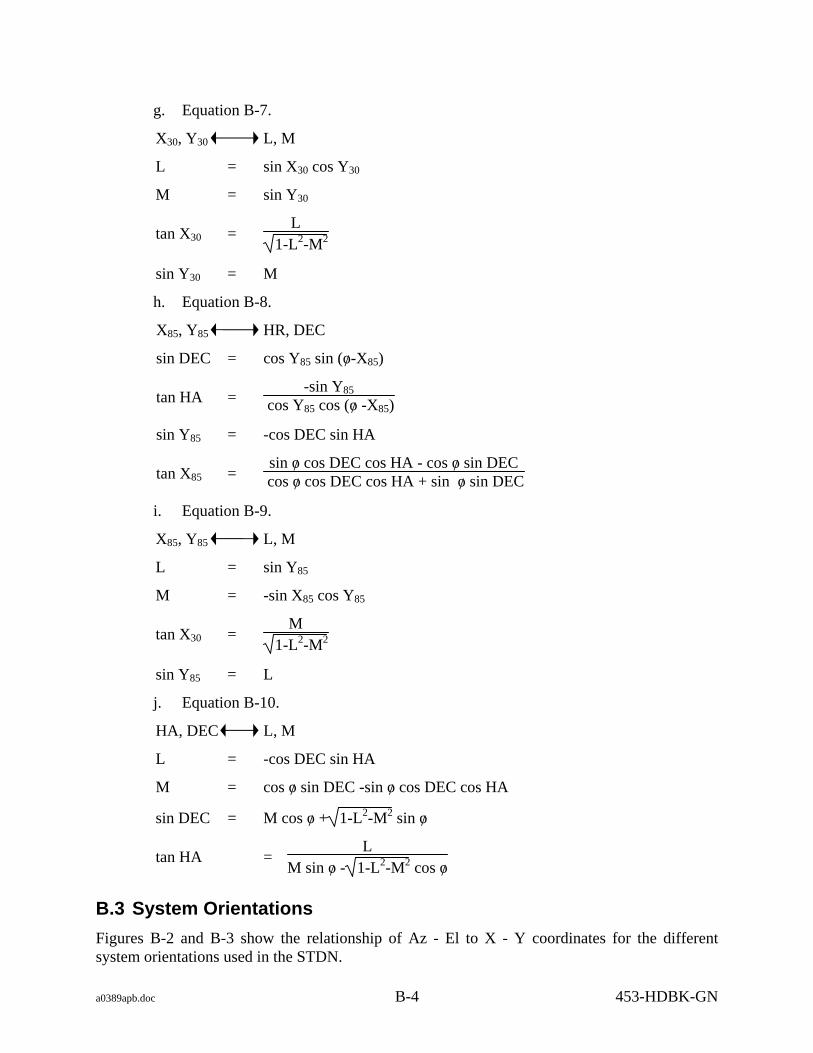
a0389apb.doc B-4 453-HDBK-GN
g. Equation B-7.
X30, Y30 L, M
L = sin X30 cos Y30
M = sin Y30
tan X30 = L
1-L2-M2
sin Y30 = M
h. Equation B-8.
X85, Y85 HR, DEC
sin DEC = cos Y85 sin (o/ -X85)
tan HA = -sin Y85
cos Y85 cos (o/ -X85)
sin Y85 = -cos DEC sin HA
tan X85 = sin o/ cos DEC cos HA - cos o/ sin DEC
cos o/ cos DEC cos HA + sin o/ sin DEC
i. Equation B-9.
X85, Y85 L, M
L = sin Y85
M = -sin X85 cos Y85
tan X30 = M
1-L2-M2
sin Y85 = L
j. Equation B-10.
HA, DEC L, M
L = -cos DEC sin HA
M = cos o/ sin DEC -sin o/ cos DEC cos HA
sin DEC = M cos o/ + 1-L2-M2 sin o/
tan HA = L
M sin o/ - 1-L2-M2 cos o/
B.3 System Orientations Figures B-2 and B-3 show the relationship of Az - El to X - Y coordinates for the different system orientations used in the STDN.

a0389apb.doc B-5 453-HDBK-GN
Figure B-1. Topocentric Cartesian Coordinates at a Station

a0389apb.doc B-6 453-HDBK-GN
NOTE: LEGEND:
X AND Y ARE 0o AT ZENITH, WITH A = AZIMUTH - - - - - - - - INCREASING -X ANGLES TO THE NORTH, E = ELEVATION - - - - - - AND INCREASING +X ANGLES TO THE X = X (LOWER) AXIS___ SOUTH. Y IS MEASURED WITH INCREASING Y = Y (UPPER) AXIS___ + ANGLES TO THE EAST, AND INCREASING - ANGLES TO THE WEST
Figure B-2. Relationship of az-el to X-Y Coordinates for 9- and 26-m Systems with +X South Orientation

a0389apb.doc B-7/(B-8 blank) 453-HDBK-GN
LEGEND: A = AZIMUTH - - - E = ELEVATION - - - X = X (LOWER) AXIS___ Y = Y (UPPER) AXIS___
Figure B-3. Relationship of az-el to X-Y Coordinates for 9-m Systems with +X East Orientation

a0389apc.doc 453-HDBK-GN
Appendix C. Station/Tracker ID

a0389apc.doc C-1 453-HDBK-GN
Appendix C. Station/Tracker ID
Appendix C provides a means of identifying stations and their data and a cross-reference for station names, equipment, and numbers. It contains the following tables:
a. Table C-1, External Station IDs (Low-speed Data). (Refer to Table 14 NASA Directory of Station Locations (NDOSL), http://fdf.gsfc.nasa.gov/prod_center/.
b. Table C-2, External Station IDs (2.4-kb High-speed Data).
c. Table C-3, Station Acronym/ID/Tracker Cross-Reference (Refer to Table 12 NASA Directory of Station Locations (NDOSL), http://fdf.gsfc.nasa.gov/prod_center/.

a0389apc.doc C-2 453-HDBK-GN
Table C-1. External Station IDs (Low-speed Data) (Example from NDOSL)
ESN STDN ESN STDN ESN STDN NUMBER CODE NUMBER CODE NUMBER CODE ------------ ------------ ------------ 2 KMRF 27 D27D 56 LBVS 3 ANPC 27 ULA4 57 RTKS 3 MA2C 28 GD28 58 HTSS 3 VDB3 28 KIXS 59 TTSS 4 CALY 29 AG1S 60 GTSS 4 WPSA 29 WH6F 61 DS61 5 NHSS 30 SG1S 61 HOLF 5 WPSS 30 WH9F 62 HBK3 6 BLKQ 31 DAKS 63 DS63 6 VT2S 32 ULAE 63 FTHF 7 WHSF 33 ATLS 63 HB33 7 WPS8 34 DS34 64 GILE 8 VTSS 34 KA2S 64 GT2S 8 WP2S 35 HT2S 64 WAPS 9 BANF 36 JSCJ 65 DS65 9 FR2F 37 NH2S 66 CN4F 9 WHSK 37 WP3S 66 DS66 10 WH2K 38 PDLS 67 CALC 11 WH3K 39 EAFF 67 KGLQ 12 DS12 39 SF1S 68 GLAS

a0389apc.doc C-3 453-HDBK-GN
Table C-2. External Station IDs (2.4-kb/sec High-speed Data) (1 of 3)
ID HEX ID Binary Format (Note)
Station Location
001 0 0000 0001 0 0.14 (PATQ) 4 UCS-1 Merritt Island/Contraves
002 0 0000 0010 0 0.13 (PA2Q) 4 UCS-2 Merritt Island/Contraves
003 0 0000 0011 4 UCS-3 CCAFS/Contraves 005 0 0000 0101 4 UCS-5 Merritt Island/Contraves 006 0 0000 0110 4 UCS-6 Merritt Island/Contraves 007 0 0000 0111 4 UCS-7 Merritt Island/Contraves 008 0 0000 1000 4 UCS-8 CCAFS/Contraves 009 0 0000 1001 4 UCS-9 CCAFS/Contraves 00A 0 0000 1010 4 PAFB IGOR PAFB/Contraves 00B 0 0000 1011 4 CB ROTI Cocoa Beach/Contraves 00C 0 0000 1100 4 MB ROTI Melbourne Beach/Contraves 010 0 0001 0000 4 UCS-10 CCAFS/Contraves 011 0 0001 0001 RTCS ADASP CCAFS 012 0 0001 0010 - RTCS FAITH CCAFS
4 UCS-12 CCAFS/Contraves 013 0 0001 0011 0+3 CCC CCAFS/CCC-CYBER 860 014 0 0001 0100 0 1.16 (CNVF) CCAFS FPS-16 015 0 0001 0101 0 1.17 (CN3F) CCAFS MCB-17 017 0 0001 0111 4 UCS-17 Merritt Island/Contraves 018 0 0001 1000 4 UCS-18 Merritt Island/Contraves 019 0 0001 1001 4 UCS-19.2 CCAFS/Contrav 020 0 0010 0000 4 UCS-20 CCAFS/Contraves 021 0 0010 0001 4 UCS-21 CCAFS/Contraves 022 0 0010 0010 4 UCS-22 CCAFS/Contraves 023 0 0010 0011 4 UCS-23 CCAFS/Contraves 024 0 0010 0100 0 19.17 (MIMF) MILA, FL (MCB-17)
4 UCS-24 CCAFS/Contraves 025 0 0010 0101 4 UCS-25 CCAFS/Contraves
0 2.17 Jupiter, FL (MCB-17) 026 0 0010 0110 4 UCS-26 CCAFS/Contraves 027 0 0010 0111 4 HRT Merritt Island/Contraves 028 0 0010 1000 4 DSIF-71 CCAFS/Contraves
0 JDI FPQ-14

a0389apc.doc C-4 453-HDBK-GN
Table C-2. External Station IDs (2.4-kb/sec High-speed Data) (2 of 3)
ID HEX ID Binary Format (Note)
Station Location
029 0 0010 1001 4 CPX16 (RAMP) CCAFS/Contraves 02B 0 0010 1011 0 JDI 15-m az-el 02D 0 0010 1101 0 JDI 24-m az-el
040 0 0100 0000 - KMR Kwajalein alcor
051 0 0101 0001 0 Bretagne No. 1 French Guiana, SA, French radar 052 0 0101 0010 0 Bretagne No. 2 French Guiana, SA, French radar 053 0 0101 0011 0 Adour No. 1 French Guiana, SA, French radar 054 0 0101 0100 0 Adour No. 2 French Guiana, SA, French radar 055 0 0101 0101 0 NATAL French Guiana, SA, French radar 056 0 0101 0110 0 Kourou TLM French Guiana, SA. 058 0 0101 1000 0 ITEK Malabar, FL, telescope 066 0 0110 0110 - MPS-36 Merritt Island 091 0 1001 0001 0 91.14 (ANTQ) Antigua FPQ-14 092 0 1001 0010 0 91TLM-TAA8A Antigua TLM 0A1 0 1010 0001 4 D38LO CCAFS/Contraves 0A2 0 1010 0010 4 U73R95 CCAFS/Contraves 0A3 0 1010 0011 4 THEO 1.3 CCAFS/Contraves 100 1 0000 0000 0 EGL (EG2F) Eglin FPS-85 118 1 0001 1000 0 CCC MOTHER CCASFS/Contraves 120 1 0010 0000 0 ASC MOTHER ASC (12.18 VAN)/Contraves 122 1 0010 0010 4 Cont 12.2 ASC (Gannett Hill)/Contraves
4 UCS-1.75 PAFB/Contraves 126 1 0010 0110 4 Cont 12.4 ASC (Cotar Hill)/Contraves 127 1 0010 0111 4 Cont 12.3 ASC (12.15)/Contraves 130 1 0011 0000 - PMRF Point Mugu, CA 4440, FPS-16 131 1 0011 0001 - FPS-16, Pt. Mugu, CA
Ser #3 132 1 0011 0010 - PM2F Point Mugu, CA, 4445 FPS-16 133 1 0011 0011 - PM3F Point Mugu, CA, 4446 FPS-16V 135 1 0011 0101 - MPS-36 PPT

a0389apc.doc C-5 453-HDBK-GN
Table C-2. External Station IDs (2.4-kb/sec High-speed Data) (3 of 3)
ID HEX ID Binary Format (Note)
Station Location
151 1 0101 0001 14 86.18 (WLPQ) Wallops FPQ-6 152 1 0101 0010 14 86.16B (WL2F) Wallops FPS-16V (Airport) 153 1 0101 0011 14 86.16 (WLPF) Wallops FPS-16 (Island) 154 1 0101 0100 14 WPSA Wallops 9-m S-band (E-W) 161 1 0110 0001 IRIG KPTQ Kaena Pt., HA, FPQ-14 162 1 0110 0010 IRIG PPTQ Pt. Pillar, CA, FPQ-6 168 1 0110 1000 13 FTHF Ft Huachuca, AZ, FPS-16 169 1 0110 1001 13 R123 (HOLF) Holloman AFB, NM, FPS-16
S-band (E-W)
173 1 0111 0011 IRIG SN7 (SNIF) San Nicolas Island FPS-16.2 174 1 0111 0100 IRIG SN13 (SN2F) San Nicolas Island FPS-16.3 175 1 0111 0101 IRIG SN15 (SN3F) San Nicolas Island FPS-16.4
4 UCS-1.75 Patrick AFB, FL/Contraves 176 1 0111 0110 IRIG R34 (FRCF) Dryden Flight Test Center
FPS-16 177 1 0111 0111 IRIG R38 (EAFF) Edwards AFB, CA, FPS-16.1
179 1 0111 1001 13 1.1 (MTLF) Ft Huachuca, AZ, Capri (Mt. Lemon) 180 1 1000 0000 13 R127 (WH6F) Stallion, NM FPS-16 181 1 1000 0001 13 12.6 (FT2F) Ft. Huachuca, AZ, FPS-16 (Scott Pk) 182 1 1000 0010 13 R124 (WH9F) Phillips Hill, NM, FPS-16 183 1 1000 0011 13 R125 (TULF) Wilde Site, NM, FPS-16 191 1 1001 0001 0 19.14 (MLAQ) MILA FPQ-14 192 1 1001 0010 0 M13Z MILA 193 1 1001 0011 14 MIL3 (ANT1) MILA 9-m S-band (N-S) 194 1 1001 0100 14 MILA (ANT2) MILA 9-m S-band (E-W) 195 1 1001 0101 0 TEL IV (TAA24) MILA
NOTE Format 0 Equal LTAS data to GN stations from CCC. Equal ETR radar E, F, and G format to CCC. Format 3 Equal Multiplexed, multi-object format output from CCC. Format 4 Equal Contraves site optical data format to CCC (Mother sites also convert this data and transmit a zero format to CCC). Format 13 Equal White Sands radar azimuth/elevation/range format to CCC. Format 14 Equal MDDF data to CCC and other users.

a0389apc.doc C-6 453-HDBK-GN
Table C-3. Station Acronym/ID/Tracker Cross-reference (Example from NDOSL)
STDN NASA CODE NUMBER EQUIPMENT ----------- ----------------------------------------------- Alamo Peak ALAY 1707 Tlm S-bd 7.3m TAS az-el Alice Springs ALSJ 0204 BRT 2-ft manual az-el Am Samoa AMSJ 0205 BRT 2-ft manual az-el Anderson Peak ANPC 0623 Camera DMI TV az-el Antigua AN3S 1704 S-bd 10m az-el AN8S 1705 S-bd 24m az-el ANTQ 4087 C-bd FPQ-14 8.8m az-el on-axis Arequipa AREL 7907 Laser-SAO AscensioN Island ASNS 1726 S-bd 4m az-el Ascension Island AC2J 0208 BRT 2-ft manual az-el ACN3 1306 USB 9m X-Y n-s ACNJ 0207 BRT 2-ft manual az-el AS2Q 4765 C-bd TPQ-11 8.8m, az-el ASCQ 4045 C-bd FPQ-15 8.5m az-el on-axis

a0389apd.doc 453-HDBK-GN
Appendix D. Vehicle Identification Assignment Conventions

a0389apd.doc D-1 453-HDBK-GN
Appendix D. Vehicle Identification Assignment Conventions
D.1 Nonshuttle
D.1.1 The VID number is assigned prior to launch. For unmanned missions, the mated launch vehicle is numbered sequentially starting with the Spacecraft (SC) or top most stage.
D.1.2 Spacecraft VID always equals 1. Other VIDs are as follows:
Launch Vehicle Type Stage No. VID No.
Two-stage 2nd 2
Three-stage 3rd 2
2nd 3
NOTE
In case of a multiple launch, the launch vehicle will use the same Satellite Identification Code (SIC) as the designated primary payload. The secondary payload will use a distinct SIC, and a VID of 1.

a0389apd.doc D-2 453-HDBK-GN
D.2 Shuttle The Shuttle Orbiter, Solid Rocket Boosters (SRB), Interim Upper Stage (IUS), Shuttle Upper Stage (SUS), and external tank use a SIC and VID distinct from the payload SIC and VID:
a. External tank = 2
b. SRB (left) = 3.
c. SRB (right) = 4.
d. Orbiter = 5.
e. Interim Upper Stage = 6.
f. Shuttle Upper Stage = 7.
g. See Figure D-1 for an example of the Shuttle VID.
NOTE
For SN applications, Vehicle Body Number is referred to as "VIC" (Vehicle Identification Code), whereas the GN refers to Vehicle Body Number as "VID" (Vehicle ID). VID in SN applications is not limited to Vehicle Body Number. Refer to the Support Identification Code Dictionary, CSOC-GSFC-DICT-002184.

Figure D-1. Example of Shuttle SIC and VID Assignments
ORBITER SIC 2XXX, VID 05
SOLID ROCKET BOOSTER (LEFT)SIX 2XXX, VID 03
EXTERNAL TANKSIC 2XXX, VID 02
SOLID ROCKET BOOSTER (RIGHT)SIC 2XXX, VID 04
PAYLOADSIC YYYY, VID 01
SHUTTLE UPPER STAGE SIX 2XXX, VID 07INTERIM UPPER STAGE SIC 2XXX, VID 06
A0389006.DRW:X:N

a0389ape.doc 453-HDBK-GN
Appendix E. Tracking Data Format Capabilities

a0389ape.doc E-1 453-HDBK-GN
Appendix E. Tracking Data Format Capabilities
Appendix E (Table E-1) provides a quick reference for the types of tracking data provided by the stations. The listing is presented in the numerical sequence of the tracker ID. Contact the GN station for current information concerning tracking capabilities.

a0389ape.doc E-2 453-HDBK-GN
Table E-1. Tracking Data Format Capabilities (1 of 4)
Format and Paragraph References Low-speed High-speed
UTDF 4.2.2
Radar 46-character
4.2.4
Tracker Acronym
Tracker ID
MDDF 4.3.2
UTDF 4.3.3
LTAS 3.2.4
X VDB3 S03(1) X X(2) CALY W04
X WPSA S04 X X X WPSS S05 NHSS A05 VT2S A06 X WHSF W07
X WPS8 S07 X WP2S S08 VTSS A08
X WHSK T09 X WH2K T10 WH3K T11 X HAWF P12
X AG3V S13 X X MTLF W14 GB2Y E15 MTLS W15 X PM3F P18 X PMRF P23

a0389ape.doc E-3 453-HDBK-GN
Table E-1. Tracking Data Format Capabilities (2 of 4)
Format and Paragraph References Low-speed High-speed
UTDF 4.2.2
Radar 46-character
4.2.4
Tracker Acronym
Tracker ID
MDDF 4.3.2
UTDF 4.3.3
LTAS 3.2.4
X GWM3 S24 X MLRL M25 AMEY S26
X ULA4 N27 X X WH6F W29 X WH9F W30
X ULAE S32 X X HA2Y S34 X WP3S S37 X PDLS S38 EAFF W39 X
X MILA S40 X X X(2) FRCF W43 X TIDD D43 WLPE N44 X FT2F W44 PPTY W45
X CAN8 D46 X X X(2) X PPTQ W46 X CALF W47 X CALT W48 CA2F W49 X
X SEYS A50 X PPTF W50 X GTKQ E51 X WL2F Z52 X X WLPF Z53 X X
X AG03 S54 X X PM4F P54 FORF S55

a0389ape.doc E-4 453-HDBK-GN
Table E-1. Tracking Data Format Capabilities (3 of 4)
Format and Paragraph References Low-speed High-speed
UTDF 4.2.2
Radar 46-character
4.2.4
Tracker Acronym
Tracker ID
MDDF 4.3.2
UTDF 4.3.3
LTAS 3.2.4
EG2F A56 GILE N56 HTSS A58 TTSS A59 GTSS A60 X HOLF W61 ATMY W62 MADD D63 X FTHF W63 GT2S A64 CNVF E65 X
X RID8 D66 X X X(2) CN3F E66 X
X AG04 S67 X X KPTQ P68 X KASR S68 X KMRQ P69 X X ASCQ E70 X X MLAQ E71 X
X MIL3 S71 X X X(2) X ACNZ S72 X ASCF E75 X
X UL23 S79 X X WLPQ Z86 X
X DFRS S89 X X UL33 S90 X SYNC W90 X ANTQ E91 X X KRUF M92

a0389ape.doc E-5/(E-6 blank) 453-HDBK-GN
Table E-1. Tracking Data Format Capabilities (4 of 4)
Format and Paragraph References Low-speed High-speed
UTDF 4.2.2
Radar 46-character
4.2.4
Tracker Acronym
Tracker ID
MDDF 4.3.2
UTDF 4.3.3
LTAS 3.2.4
KM2F P92 X ACNY S93 X TULF W93 SN3F P96 X SN2F P97 X SNIF P98 X
NOTE 1. VDB3 also has IRIG capabilities (4.3.4). 2. Input only.

A0389apf.doc 453-HDBK-GN
Appendix F. Status Tape Block Types

A0389apf.doc F-i /(F-ii blank) 453-HDBK-GN
Appendix F. Contents
F.1 Dynamic System Status Tape: Block Type 1....................................................................F-1
F.1.1 RTPS ......................................................................................................................F-1
F.1.2 STPS.....................................................................................................................F-12
F.2 Static System Status Tape: Block Type 2 .......................................................................F-69
F.2.1 RTPS ....................................................................................................................F-69
F.2.2 STPS.....................................................................................................................F-85
F.3 Static System Status Tape: Block Type 3 .......................................................................F-81
F.3.1 RTPS ....................................................................................................................F-81
F.3.2 STPS.....................................................................................................................F-83
F.4 Static System Status Tape: Block Type 4 (RTPS) ..........................................................F-86
F.5 Static System Status Tape: Block Type 5 (STPS)...........................................................F-88

a0389apf.doc F-1 453-HDBK-GN
Appendix F. Status Tape Block Types
F.1 Dynamic System Status Tape: Block Type 1
F.1.1 RTPS
F.1.1.1 Overview Each tape block type 1 contains an array of 10 records.
BYTE 0 DESCRIPTION TAPE BLOCK 1 RECORD 0
BYTE 704G6 DESCRIPTION TAPE BLOCK 1 RECORD 1
BYTE 1408 DESCRIPTION TAPE BLOCK 1 RECORD 2
BYTE 2112 DESCRIPTION TAPE BLOCK 1 RECORD 3
BYTE 2816 DESCRIPTION TAPE BLOCK 1 RECORD 4
BYTE 3520 DESCRIPTION TAPE BLOCK 1 RECORD 5
BYTE 4224 DESCRIPTION TAPE BLOCK 1 RECORD 6
BYTE 4728 DESCRIPTION TAPE BLOCK 1 RECORD 7
BYTE 5432 DESCRIPTION TAPE BLOCK 1 RECORD 8
BYTE 6136 DESCRIPTION TAPE BLOCK 1 RECORD 9
BYTES 6840 - 11999 DESCRIPTION SPARE
F.1.1.2 Record description BYTE 0 DESCRIPTION TAPE BLOCK SEQUENCE COUNT 15 14 13 12 11 10 9 8 7 6 5 4 3 2 1 0
BYTE 2 DESCRIPTION TAPE BLOCK TYPE 7 6 5 4 3 2 1 0 Dynamic System Status 1 BYTE 3

a0389apf.doc F-2 453-HDBK-GN
DESCRIPTION SYSTEM ID 7 6 5 4 3 2 1 0 1 = RTPS 2 = STPS
BYTE 4 DESCRIPTION ANTENNA GEO 7 6 5 4 3 2 1 0 1 = AZ EL 2 = X Y 3 = X Y PRIME
BYTE 5 DESCRIPTION VALID RECORD 7 6 5 4 3 2 1 0 1 = VALID 0 = INVALID
BYTE 6 DESCRIPTION REAL TIME = DAY OF YEAR 15 14 13 12 11 10 9 8 7 6 5 4 3 2 1 0
DESCRIPTION REAL TIME = MILLISECS OF DAY 15 14 13 12 11 10 9 8 7 6 5 4 3 2 1 0 31 30 29 28 27 26 25 24 23 22 21 20 19 18 17 16
DESCRIPTION REAL TIME = MICROSECS OF MILLISECS 15 14 13 12 11 10 9 8 7 6 5 4 3 2 1 0
DESCRIPTION REAL TIME = YEAR 15 14 13 12 11 10 9 8 7 6 5 4 3 2 1 0
BYTE 16 DESCRIPTION SIMULATED TIME = DAY OF YEAR 15 14 13 12 11 10 9 8 7 6 5 4 3 2 1 0
DESCRIPTION SIMULATED TIME = MILLISECS OF DAY 15 14 13 12 11 10 9 8 7 6 5 4 3 2 1 0 31 30 29 28 27 26 25 24 23 22 21 20 19 18 17 16
DESCRIPTION SIMULATED TIME = MICROSECS OF MILLISECS 15 14 13 12 11 10 9 8 7 6 5 4 3 2 1 0
DESCRIPTION SIMULATED TIME = YEAR 15 14 13 12 11 10 9 8 7 6 5 4 3 2 1 0
BYTE 26 DESCRIPTION LIFTOFF TIME = DAY OF YEAR 15 14 13 12 11 10 9 8 7 6 5 4 3 2 1 0
DESCRIPTION LIFTOFF TIME = MILLISECS OF DAY 15 14 13 12 11 10 9 8 7 6 5 4 3 2 1 0 31 30 29 28 27 26 25 24 23 22 21 20 19 18 17 16
DESCRIPTION LIFTOFF TIME = MICROSECS OF MILLISECS 15 14 13 12 11 10 9 8 7 6 5 4 3 2 1 0
DESCRIPTION LIFTOFF TIME = YEAR 15 14 13 12 11 10 9 8 7 6 5 4 3 2 1 0

a0389apf.doc F-3 453-HDBK-GN
BYTE 36 DESCRIPTION SYSTEM RUN TIME = DAY OF YEAR 15 14 13 12 11 10 9 8 7 6 5 4 3 2 1 0
DESCRIPTION SYSTEM RUN TIME = MILLISECS OF DAY 15 14 13 12 11 10 9 8 7 6 5 4 3 2 1 0 31 30 29 28 27 26 25 24 23 22 21 20 19 18 17 16
DESCRIPTION SYSTEM RUN TIME = MICROSECS OF MILLISECS 15 14 13 12 11 10 9 8 7 6 5 4 3 2 1 0
DESCRIPTION SYSTEM RUN TIME = YEAR 15 14 13 12 11 10 9 8 7 6 5 4 3 2 1 0
BYTE 46 DESCRIPTION CURRENT DESIGNATE SOURCE 7 6 5 4 3 2 1 0
Value Source Value Source Value Source 1 IRV A 2 OTE A 3 LRV A 4 IIRV A 5 NORAD A 6 MDDF A 7 LTAS A 8 INP A 9 MANUAL TABLE 10 IRV B 11 OTE B 12 LRV B 13 IIRV B 14 NORAD B 15 MDDF B 16 LTAS B 17 INP B 18 BROUWER A 19 BROUWER B 20 EPV A 21 EPV B
BYTE 47 DESCRIPTION VALID AVAILABLE DESIGINATE SOURCES =
BROUWER MEAN A 7 6 5 4 3 2 1 0 1 = AVAILABLE 0 = NOT AVAILABLE
BYTE 48 DESCRIPTION VALID AVAILABLE DESIGINATE SOURCES =
BROUWER MEAN B 7 6 5 4 3 2 1 0 1 = AVAILABLE 0 = NOT AVAILABLE
BYTE 49 DESCRIPTION SPARE (RESERVED FOR STPS) 7 6 5 4 3 2 1 0
BYTE 50 DESCRIPTION VALID AVAILABLE DESIGINATE SOURCES =
EXTENDED PRECISION VECTORS A 7 6 5 4 3 2 1 0 1 = AVAILABLE 0 = NOT AVAILABLE
BYTE 51 DESCRIPTION VALID AVAILABLE DESIGINATE SOURCES =
EXTENDED PRECISION VECTORS B 7 6 5 4 3 2 1 0 1 = AVAILABLE 0 = NOT AVAILABLE

a0389apf.doc F-4 453-HDBK-GN
BYTE 52 DESCRIPTION SPARE (RESERVED FOR STPS) 7 6 5 4 3 2 1 0
BYTE 53 DESCRIPTION VALID AVAILABLE DESIGINATE SOURCES = IIRV A 7 6 5 4 3 2 1 0 1 = AVAILABLE 0 = NOT AVAILABLE
BYTE 54 DESCRIPTION VALID AVAILABLE DESIGINATE SOURCES = IIRV B 7 6 5 4 3 2 1 0 1 = AVAILABLE 0 = NOT AVAILABLE
BYTE 55 DESCRIPTION SPARE (RESERVED FOR STPS) 7 6 5 4 3 2 1 0
BYTE 56 DESCRIPTION VALID AVAILABLE DESIGINATE SOURCES = INP A 7 6 5 4 3 2 1 0 1 = AVAILABLE 0 = NOT AVAILABLE
BYTE 57 DESCRIPTION VALID AVAILABLE DESIGINATE SOURCES = INP B 7 6 5 4 3 2 1 0 1 = AVAILABLE 0 = NOT AVAILABLE
BYTE 58 DESCRIPTION SPARE (RESERVED FOR STPS) 7 6 5 4 3 2 1 0
BYTE 59 DESCRIPTION VALID AVAILABLE DESIGINATE SOURCES = IRV A 7 6 5 4 3 2 1 0 1 = AVAILABLE 0 = NOT AVAILABLE
BYTE 60 DESCRIPTION VALID AVAILABLE DESIGINATE SOURCES = IRV B 7 6 5 4 3 2 1 0 1 = AVAILABLE 0 = NOT AVAILABLE
BYTE 61 DESCRIPTION SPARE (RESERVED FOR STPS) 7 6 5 4 3 2 1 0
BYTE 62 DESCRIPTION VALID AVAILABLE DESIGINATE SOURCES = LRV A 7 6 5 4 3 2 1 0 1 = AVAILABLE 0 = NOT AVAILABLE
BYTE 63 DESCRIPTION VALID AVAILABLE DESIGINATE SOURCES = LRV B 7 6 5 4 3 2 1 0 1 = AVAILABLE 0 = NOT AVAILABLE BYTE 64

a0389apf.doc F-5 453-HDBK-GN
DESCRIPTION SPARE (RESERVED FOR STPS) 7 6 5 4 3 2 1 0
BYTE 65 DESCRIPTION VALID AVAILABLE DESIGINATE SOURCES = LTAS A 7 6 5 4 3 2 1 0 1 = AVAILABLE 0 = NOT AVAILABLE
BYTE 66 DESCRIPTION VALID AVAILABLE DESIGINATE SOURCES = LTAS B 7 6 5 4 3 2 1 0 1 = AVAILABLE 0 = NOT AVAILABLE
BYTE 67 DESCRIPTION SPARE (RESERVED FOR STPS) 7 6 5 4 3 2 1 0
BYTE 68 DESCRIPTION VALID AVAILABLE DESIGINATE SOURCES =
MANUAL TABLE 7 6 5 4 3 2 1 0 1 = AVAILABLE 0 = NOT AVAILABLE
BYTE 69 DESCRIPTION VALID AVAILABLE DESIGINATE SOURCES = MDDF A 7 6 5 4 3 2 1 0 1 = AVAILABLE 0 = NOT AVAILABLE
BYTE 70 DESCRIPTION VALID AVAILABLE DESIGINATE SOURCES = MDDF B 7 6 5 4 3 2 1 0 1 = AVAILABLE 0 = NOT AVAILABLE
BYTE 71 DESCRIPTION SPARE (RESERVED FOR STPS) 7 6 5 4 3 2 1 0
BYTE 72 DESCRIPTION VALID AVAILABLE DESIGINATE SOURCES = NORAD A 7 6 5 4 3 2 1 0 1 = AVAILABLE 0 = NOT AVAILABLE
BYTE 73 DESCRIPTION VALID AVAILABLE DESIGINATE SOURCES (SPARE) 7 6 5 4 3 2 1 0

a0389apf.doc F-6 453-HDBK-GN
BYTE 79 DESCRIPTION VALID MESSAGE BIT FLAGS 15 14 13 12 11 10 9 8 7 6 5 4 3 2 1 0 31 30 29 28 27 26 25 24 23 22 21 20 19 18 17 16 Bit set to 1 = Message Valid in this record. INPUT BIT Message type BIT Message type 5 MDDF A 6 LTAS A 14 MDDF B 15 LTAS B OUTPUT BIT Message type BIT Message type BIT Message type 21 MDDF A 22 MDDF B 23 LTAS A 24 LTAS B 25 NORAD 26 46CHAR 28 IRV A 29 IRV B
BYTE 83 DESCRIPTION OUTPUT ENABLE STATUS FLAGS 7 6 5 4 3 2 1 0
Bit set to 1 = output enabled for this message type. BIT Message type BIT Message type 0 MDDF 1 LTAS 2 46CHAR 3 NORAD
BYTE 84 DESCRIPTION INPUT MDDF A MESSAGE 7 6 5 4 3 2 1 0 Up to 30 bytes (see MDDF description for format)
BYTE 114 DESCRIPTION INPUT MDDF B MESSAGE 7 6 5 4 3 2 1 0 Up to 30 bytes (see MDDF description for format)
BYTE 144 DESCRIPTION INPUT LTAS A MESSAGE 7 6 5 4 3 2 1 0 Up to 30 bytes (see LTAS description for format)
BYTE 174 DESCRIPTION INPUT LTAS B MESSAGE 7 6 5 4 3 2 1 0 Up to 30 bytes (see LTAS description for format)

a0389apf.doc F-7 453-HDBK-GN
BYTE 204 DESCRIPTION OUTPUT MDDF A MESSAGE 7 6 5 4 3 2 1 0 Up to 30 bytes (see MDDF description for format)
BYTE 234 DESCRIPTION OUTPUT MDDF B MESSAGE 7 6 5 4 3 2 1 0 Up to 30 bytes (see MDDF description for format)
BYTE 264 DESCRIPTION OUTPUT LTAS A MESSAGE 7 6 5 4 3 2 1 0 Up to 30 bytes (see LTAS description for format)
BYTE 294 DESCRIPTION OUTPUT LTAS B MESSAGE 7 6 5 4 3 2 1 0 Up to 30 bytes (see LTAS description for format)
BYTES 324 - 398 DESCRIPTION SPARE (RESERVED FOR STPS) 7 6 5 4 3 2 1 0
BYTE 399 DESCRIPTION 46 CHAR OUTPUT MESSAGE 7 6 5 4 3 2 1 0 Up to 56 bytes (see 46 CHAR description for format)
BYTE 455 DESCRIPTION NORAD TYPE 2 B3 OUTPUT MESSAGE 7 6 5 4 3 2 1 0 Up to 59 bytes (see NORAD TYPE 2 B3 description for format)
BYTE 514 DESCRIPTION TIME BIAS = DAY OF YEAR 15 14 13 12 11 10 9 8 7 6 5 4 3 2 1 0
BYTE 516 DESCRIPTION TIME BIAS = MILLISECS OF DAY 15 14 13 12 11 10 9 8 7 6 5 4 3 2 1 0 31 30 29 28 27 26 25 24 23 22 21 20 19 18 17 16
BYTE 520 DESCRIPTION TIME BIAS = MICROSECS OF MILLISECS 15 14 13 12 11 10 9 8 7 6 5 4 3 2 1 0

a0389apf.doc F-8 453-HDBK-GN
BYTE 522 DESCRIPTION TIME BIAS = YEAR 15 14 13 12 11 10 9 8 7 6 5 4 3 2 1 0
BYTE 524 DESCRIPTION ANGLE 1 BIAS (AZ, or X, or X') UNITS = RADIANS 15 14 13 12 11 10 9 8 7 6 5 4 3 2 1 0 31 30 29 28 27 26 25 24 23 22 21 20 19 18 17 16 47 46 45 44 43 42 41 40 39 38 37 36 35 34 33 32 63 62 61 60 59 58 57 56 55 54 53 52 51 50 49 48 DOUBLE
BYTE 532 DESCRIPTION ANGLE 2 BIAS (EL, or Y, or Y') UNITS = RADIANS 15 14 13 12 11 10 9 8 7 6 5 4 3 2 1 0 31 30 29 28 27 26 25 24 23 22 21 20 19 18 17 16 47 46 45 44 43 42 41 40 39 38 37 36 35 34 33 32 63 62 61 60 59 58 57 56 55 54 53 52 51 50 49 48 DOUBLE
BYTE 540 DESCRIPTION RANGE BIAS UNITS = METERS 15 14 13 12 11 10 9 8 7 6 5 4 3 2 1 0 31 30 29 28 27 26 25 24 23 22 21 20 19 18 17 16 47 46 45 44 43 42 41 40 39 38 37 36 35 34 33 32 63 62 61 60 59 58 57 56 55 54 53 52 51 50 49 48 DOUBLE
BYTE 548 DESCRIPTION CURRENT RANGE UNITS = METERS 15 14 13 12 11 10 9 8 7 6 5 4 3 2 1 0 31 30 29 28 27 26 25 24 23 22 21 20 19 18 17 16 47 46 45 44 43 42 41 40 39 38 37 36 35 34 33 32 63 62 61 60 59 58 57 56 55 54 53 52 51 50 49 48 DOUBLE
BYTE 556 DESCRIPTION CURRENT ANGLE 1 (AZ, or X, or X') UNITS = RADIANS 15 14 13 12 11 10 9 8 7 6 5 4 3 2 1 0 31 30 29 28 27 26 25 24 23 22 21 20 19 18 17 16 47 46 45 44 43 42 41 40 39 38 37 36 35 34 33 32 63 62 61 60 59 58 57 56 55 54 53 52 51 50 49 48 DOUBLE
BYTE 564 DESCRIPTION CURRENT ANGLE 2 (EL, or Y, or Y') UNITS = RADIANS 15 14 13 12 11 10 9 8 7 6 5 4 3 2 1 0 31 30 29 28 27 26 25 24 23 22 21 20 19 18 17 16 47 46 45 44 43 42 41 40 39 38 37 36 35 34 33 32 63 62 61 60 59 58 57 56 55 54 53 52 51 50 49 48 DOUBLE

a0389apf.doc F-9 453-HDBK-GN
BYTE 572 DESCRIPTION CURRENT TIME TAG = DAY OF YEAR 15 14 13 12 11 10 9 8 7 6 5 4 3 2 1 0
DESCRIPTION CURRENT TIME TAG = MILLISECS OF DAY 15 14 13 12 11 10 9 8 7 6 5 4 3 2 1 0 31 30 29 28 27 26 25 24 23 22 21 20 19 18 17 16
DESCRIPTION CURRENT TIME TAG = MICROSECS OF MILLISECS 15 14 13 12 11 10 9 8 7 6 5 4 3 2 1 0
DESCRIPTION CURRENT TIME TAG = YEAR 15 14 13 12 11 10 9 8 7 6 5 4 3 2 1 0
BYTE 582 DESCRIPTION CURRENT DOPPLER UNITS = HZ 15 14 13 12 11 10 9 8 7 6 5 4 3 2 1 0 31 30 29 28 27 26 25 24 23 22 21 20 19 18 17 16 47 46 45 44 43 42 41 40 39 38 37 36 35 34 33 32 63 62 61 60 59 58 57 56 55 54 53 52 51 50 49 48 DOUBLE
BYTE 590 DESCRIPTION TRANSMIT FREQ. FOR DOPPLER CALC UNITS = HZ 15 14 13 12 11 10 9 8 7 6 5 4 3 2 1 0 31 30 29 28 27 26 25 24 23 22 21 20 19 18 17 16 47 46 45 44 43 42 41 40 39 38 37 36 35 34 33 32 63 62 61 60 59 58 57 56 55 54 53 52 51 50 49 48 DOUBLE
BYTE 598 DESCRIPTION DESIGNATE RANGE UNITS = METERS 15 14 13 12 11 10 9 8 7 6 5 4 3 2 1 0 31 30 29 28 27 26 25 24 23 22 21 20 19 18 17 16 47 46 45 44 43 42 41 40 39 38 37 36 35 34 33 32 63 62 61 60 59 58 57 56 55 54 53 52 51 50 49 48 DOUBLE
BYTE 606 DESCRIPTION DESIGNATE ANGLE 1 (AZ, or X, or X') UNITS = RADIANS 15 14 13 12 11 10 9 8 7 6 5 4 3 2 1 0 31 30 29 28 27 26 25 24 23 22 21 20 19 18 17 16 47 46 45 44 43 42 41 40 39 38 37 36 35 34 33 32 63 62 61 60 59 58 57 56 55 54 53 52 51 50 49 48 DOUBLE
BYTE 614 DESCRIPTION DESIGNATE ANGLE 2 (EL, or Y, or Y') UNITS = RADIANS 15 14 13 12 11 10 9 8 7 6 5 4 3 2 1 0 31 30 29 28 27 26 25 24 23 22 21 20 19 18 17 16 47 46 45 44 43 42 41 40 39 38 37 36 35 34 33 32 63 62 61 60 59 58 57 56 55 54 53 52 51 50 49 48 DOUBLE
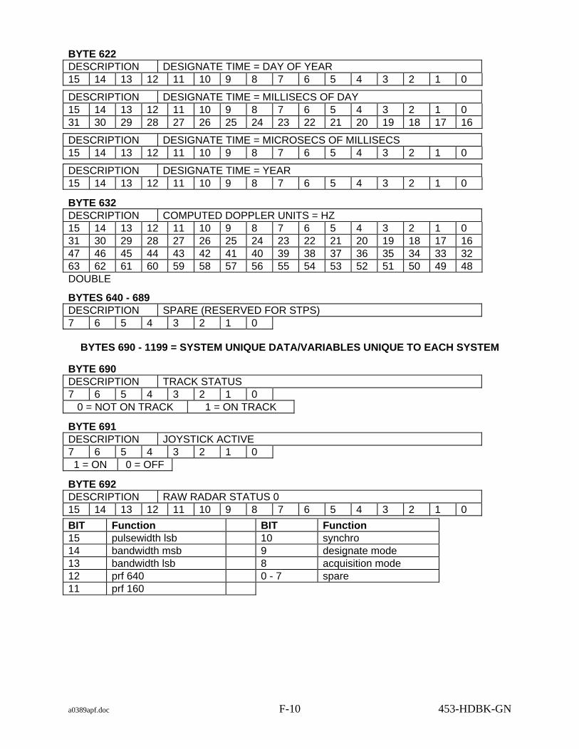
a0389apf.doc F-10 453-HDBK-GN
BYTE 622 DESCRIPTION DESIGNATE TIME = DAY OF YEAR 15 14 13 12 11 10 9 8 7 6 5 4 3 2 1 0
DESCRIPTION DESIGNATE TIME = MILLISECS OF DAY 15 14 13 12 11 10 9 8 7 6 5 4 3 2 1 0 31 30 29 28 27 26 25 24 23 22 21 20 19 18 17 16
DESCRIPTION DESIGNATE TIME = MICROSECS OF MILLISECS 15 14 13 12 11 10 9 8 7 6 5 4 3 2 1 0
DESCRIPTION DESIGNATE TIME = YEAR 15 14 13 12 11 10 9 8 7 6 5 4 3 2 1 0
BYTE 632 DESCRIPTION COMPUTED DOPPLER UNITS = HZ 15 14 13 12 11 10 9 8 7 6 5 4 3 2 1 0 31 30 29 28 27 26 25 24 23 22 21 20 19 18 17 16 47 46 45 44 43 42 41 40 39 38 37 36 35 34 33 32 63 62 61 60 59 58 57 56 55 54 53 52 51 50 49 48 DOUBLE
BYTES 640 - 689 DESCRIPTION SPARE (RESERVED FOR STPS) 7 6 5 4 3 2 1 0
BYTES 690 - 1199 = SYSTEM UNIQUE DATA/VARIABLES UNIQUE TO EACH SYSTEM
BYTE 690 DESCRIPTION TRACK STATUS 7 6 5 4 3 2 1 0
0 = NOT ON TRACK 1 = ON TRACK
BYTE 691 DESCRIPTION JOYSTICK ACTIVE 7 6 5 4 3 2 1 0 1 = ON 0 = OFF
BYTE 692 DESCRIPTION RAW RADAR STATUS 0 15 14 13 12 11 10 9 8 7 6 5 4 3 2 1 0
BIT Function BIT Function 15 pulsewidth lsb 10 synchro 14 bandwidth msb 9 designate mode 13 bandwidth lsb 8 acquisition mode 12 prf 640 0 - 7 spare 11 prf 160

a0389apf.doc F-11 453-HDBK-GN
BYTE 694 DESCRIPTION RAW RADAR STATUS 1 15 14 13 12 11 10 9 8 7 6 5 4 3 2 1 0
BIT Function 12 - 15 spare 11 radiation on 10 lo sngl dual 9 paramp on 8 skin beacon 7 valid angle track 6 ang man dig 5 rng man dig 4 src3 designate 3 src2 designate 2 angle coast on 1 agc on 0 pulsewidth msb
BYTE 696 DESCRIPTION RAW RADAR STATUS 2 15 14 13 12 11 10 9 8 7 6 5 4 3 2 1 0
BIT Function 4 - 15 spare 3 operate test 2 range verified 1 valid range lock number status bit 0 spare
BYTE 698 DESCRIPTION AZ ERROR 15 14 13 12 11 10 9 8 7 6 5 4 3 2 1 0 12 bits (0 - 11 valid)
BYTE 700 DESCRIPTION EL ERROR 15 14 13 12 11 10 9 8 7 6 5 4 3 2 1 0 12 bits (0 - 11 valid)
BYTE 702 DESCRIPTION AGC 15 14 13 12 11 10 9 8 7 6 5 4 3 2 1 0 12 bits (0 - 11 valid)
BYTE 704 DESCRIPTION START OF NEXT RECORD OR SPARE 7 6 5 4 3 2 1 0

a0389apf.doc F-12 453-HDBK-GN
F.1.2 STPS
F.1.2.1 Overview The size of each tape block type 1 record is 1200 bytes. An array of 10 records are in each tape block type 1.
BYTE 0 DESCRIPTION TAPE BLOCK 1 RECORD 0
BYTE 1200 DESCRIPTION TAPE BLOCK 1 RECORD 1
BYTE 2400 DESCRIPTION TAPE BLOCK 1 RECORD 2
BYTE 3600 DESCRIPTION TAPE BLOCK 1 RECORD 3
BYTE 4800 DESCRIPTION TAPE BLOCK 1 RECORD 4
BYTE 6000 DESCRIPTION TAPE BLOCK 1 RECORD 5
BYTE 7200 DESCRIPTION TAPE BLOCK 1 RECORD 6
BYTE 8400 DESCRIPTION TAPE BLOCK 1 RECORD 7
BYTE 9600 DESCRIPTION TAPE BLOCK 1 RECORD 8
BYTE 10800 DESCRIPTION TAPE BLOCK 1 RECORD 9
F.1.2.2 Record description
BYTE 0 DESCRIPTION TAPE BLOCK SEQUENCE COUNT 15 14 13 12 11 10 9 8 7 6 5 4 3 2 1 0
BYTE 2 DESCRIPTION TAPE BLOCK TYPE 7 6 5 4 3 2 1 0 1 = Dynamic System Status
BYTE 3 DESCRIPTION SYSTEM ID 7 6 5 4 3 2 1 0 1 = RTPS 2 = STPS 3 = DSTPS
BYTE 4 DESCRIPTION ANTENNA GEO 7 6 5 4 3 2 1 0 1 = AZ EL 2 = X Y 3 = X Y PRIME BYTE 5

a0389apf.doc F-13 453-HDBK-GN
DESCRIPTION VALID RECORD 7 6 5 4 3 2 1 0 1 = VALID 0 = INVALID
BYTE 6 DESCRIPTION REAL TIME 15 14 13 12 11 10 9 8 7 6 5 4 3 2 1 0
day of year
15 14 13 12 11 10 9 8 7 6 5 4 3 2 1 0 31 30 29 28 27 26 25 24 23 22 21 20 19 18 17 16
millisecs of day
15 14 13 12 11 10 9 8 7 6 5 4 3 2 1 0 microsecs of millisecs
15 14 13 12 11 10 9 8 7 6 5 4 3 2 1 0 year
BYTE 16 DESCRIPTION SIMULATED TIME 15 14 13 12 11 10 9 8 7 6 5 4 3 2 1 0
day of year
15 14 13 12 11 10 9 8 7 6 5 4 3 2 1 0 31 30 29 28 27 26 25 24 23 22 21 20 19 18 17 16
millisecs of day
15 14 13 12 11 10 9 8 7 6 5 4 3 2 1 0 microsecs of millisecs
15 14 13 12 11 10 9 8 7 6 5 4 3 2 1 0 year
BYTE 26 DESCRIPTION LIFTOFF TIME 15 14 13 12 11 10 9 8 7 6 5 4 3 2 1 0
day of year
15 14 13 12 11 10 9 8 7 6 5 4 3 2 1 0 31 30 29 28 27 26 25 24 23 22 21 20 19 18 17 16
millisecs of day
15 14 13 12 11 10 9 8 7 6 5 4 3 2 1 0 microsecs of millisecs
15 14 13 12 11 10 9 8 7 6 5 4 3 2 1 0 year

a0389apf.doc F-14 453-HDBK-GN
BYTES 36 - 45 DESCRIPTION SYSTEM RUN TIME 15 14 13 12 11 10 9 8 7 6 5 4 3 2 1 0
day of year
15 14 13 12 11 10 9 8 7 6 5 4 3 2 1 0 31 30 29 28 27 26 25 24 23 22 21 20 19 18 17 16
millisecs of day
15 14 13 12 11 10 9 8 7 6 5 4 3 2 1 0 microsecs of millisecs
15 14 13 12 11 10 9 8 7 6 5 4 3 2 1 0 year
BYTE 46 DESCRIPTION CURRENT DESIGNATE SOURCE 7 6 5 4 3 2 1 0
Value Source Value Source Value Source 1 IRV A 2 OTE A 3 LRV A 4 IIRV A 5 NORAD A 6 MDDF A 7 LTAS A 8 INP A 9 MANUAL TABLE 10 IRV B 11 OTE B 12 LRV B 13 IIRV B 14 NORAD B 15 MDDF B 16 LTAS B 17 INP B 18 BROUWER A 19 BROUWER B 20 EPV A 21 EPV B
BYTE 47 DESCRIPTION SPARE 7 6 5 4 3 2 1 0
BYTE 48 DESCRIPTION VALID AVAILABLE DESIGINATE SOURCES
BROUWER MEAN A 7 6 5 4 3 2 1 0 1 = AVAILABLE 0 = NOT AVAILABLE
BYTE 49 DESCRIPTION VALID AVAILABLE DESIGINATE SOURCES
BROUWER MEAN B 7 6 5 4 3 2 1 0 1 = AVAILABLE 0 = NOT AVAILABLE
BYTE 50 DESCRIPTION VALID AVAILABLE DESIGINATE SOURCES
BROUWER MEAN C 7 6 5 4 3 2 1 0 1 = AVAILABLE 0 = NOT AVAILABLE
BYTE 51 DESCRIPTION VALID AVAILABLE DESIGINATE SOURCES
EXTENDED PRECISION VECTORS A 7 6 5 4 3 2 1 0 1 = AVAILABLE 0 = NOT AVAILABLE BYTE 52 DESCRIPTION VALID AVAILABLE DESIGINATE SOURCES

a0389apf.doc F-15 453-HDBK-GN
EXTENDED PRECISION VECTORS B 7 6 5 4 3 2 1 0 1 = AVAILABLE 0 = NOT AVAILABLE
BYTE 53 DESCRIPTION VALID AVAILABLE DESIGINATE SOURCES
EXTENDED PRECISION VECTORS C 7 6 5 4 3 2 1 0 1 = AVAILABLE 0 = NOT AVAILABLE
BYTE 54 DESCRIPTION VALID AVAILABLE DESIGINATE SOURCES
IIRV A 7 6 5 4 3 2 1 0 1 = AVAILABLE 0 = NOT AVAILABLE
BYTE 55 DESCRIPTION VALID AVAILABLE DESIGINATE SOURCES
IIRV B 7 6 5 4 3 2 1 0 1 = AVAILABLE 0 = NOT AVAILABLE
BYTE 56 DESCRIPTION VALID AVAILABLE DESIGINATE SOURCES
IIRV C 7 6 5 4 3 2 1 0 1 = AVAILABLE 0 = NOT AVAILABLE
BYTE 57 DESCRIPTION VALID AVAILABLE DESIGINATE SOURCES
INP A 7 6 5 4 3 2 1 0 1 = AVAILABLE 0 = NOT AVAILABLE
BYTE 58 DESCRIPTION VALID AVAILABLE DESIGINATE SOURCES
INP B 7 6 5 4 3 2 1 0 1 = AVAILABLE 0 = NOT AVAILABLE
BYTE 59 DESCRIPTION VALID AVAILABLE DESIGINATE SOURCES
INP C 7 6 5 4 3 2 1 0 1 = AVAILABLE 0 = NOT AVAILABLE
BYTE 60 DESCRIPTION VALID AVAILABLE DESIGINATE SOURCES
IRV A 7 6 5 4 3 2 1 0 1 = AVAILABLE 0 = NOT AVAILABLE

a0389apf.doc F-16 453-HDBK-GN
BYTE 61 DESCRIPTION VALID AVAILABLE DESIGINATE SOURCES
IRV B 7 6 5 4 3 2 1 0 1 = AVAILABLE 0 = NOT AVAILABLE
BYTE 62 DESCRIPTION VALID AVAILABLE DESIGINATE SOURCES
IRV C 7 6 5 4 3 2 1 0 1 = AVAILABLE 0 = NOT AVAILABLE
BYTE 63 DESCRIPTION VALID AVAILABLE DESIGINATE SOURCES
LRV A 7 6 5 4 3 2 1 0 1 = AVAILABLE 0 = NOT AVAILABLE
BYTE 64 DESCRIPTION VALID AVAILABLE DESIGINATE SOURCES
LRV B 7 6 5 4 3 2 1 0 1 = AVAILABLE 0 = NOT AVAILABLE
BYTE 65 DESCRIPTION VALID AVAILABLE DESIGINATE SOURCES
LRV C 7 6 5 4 3 2 1 0 1 = AVAILABLE 0 = NOT AVAILABLE
BYTE 66 DESCRIPTION VALID AVAILABLE DESIGINATE SOURCES
LTAS A 7 6 5 4 3 2 1 0 1 = AVAILABLE 0 = NOT AVAILABLE
BYTE 67 DESCRIPTION VALID AVAILABLE DESIGINATE SOURCES
LTAS B 7 6 5 4 3 2 1 0 1 = AVAILABLE 0 = NOT AVAILABLE
BYTE 68 DESCRIPTION VALID AVAILABLE DESIGINATE SOURCES
LTAS C 7 6 5 4 3 2 1 0 1 = AVAILABLE 0 = NOT AVAILABLE
BYTE 69 DESCRIPTION VALID AVAILABLE DESIGINATE SOURCES
MANUAL TABLE 7 6 5 4 3 2 1 0 1 = AVAILABLE 0 = NOT AVAILABLE

a0389apf.doc F-17 453-HDBK-GN
BYTE 70 DESCRIPTION VALID AVAILABLE DESIGINATE SOURCES
MDDF A 7 6 5 4 3 2 1 0 1 = AVAILABLE 0 = NOT AVAILABLE
BYTE 71 DESCRIPTION VALID AVAILABLE DESIGINATE SOURCES
MDDF B 7 6 5 4 3 2 1 0 1 = AVAILABLE 0 = NOT AVAILABLE
BYTE 72 DESCRIPTION VALID AVAILABLE DESIGINATE SOURCES
MDDF C 7 6 5 4 3 2 1 0 1 = AVAILABLE 0 = NOT AVAILABLE
BYTE 73 DESCRIPTION VALID AVAILABLE DESIGINATE SOURCES
NORAD A 7 6 5 4 3 2 1 0 1 = AVAILABLE 0 = NOT AVAILABLE
BYTE 74 DESCRIPTION VALID AVAILABLE DESIGINATE SOURCES
NORAD B 7 6 5 4 3 2 1 0 1 = AVAILABLE 0 = NOT AVAILABLE
BYTE 75 DESCRIPTION VALID AVAILABLE DESIGINATE SOURCES
NORAD C 7 6 5 4 3 2 1 0 1 = AVAILABLE 0 = NOT AVAILABLE
BYTE 76 DESCRIPTION VALID AVAILABLE DESIGINATE SOURCES
OTE A 7 6 5 4 3 2 1 0 1 = AVAILABLE 0 = NOT AVAILABLE
BYTE 77 DESCRIPTION VALID AVAILABLE DESIGINATE SOURCES
OTE B 7 6 5 4 3 2 1 0 1 = AVAILABLE 0 = NOT AVAILABLE
BYTE 78 DESCRIPTION VALID AVAILABLE DESIGINATE SOURCES
SLEW 7 6 5 4 3 2 1 0 1 = AVAILABLE 0 = NOT AVAILABLE

a0389apf.doc F-18 453-HDBK-GN
BYTE 79 DESCRIPTION VALID AVAILABLE DESIGINATE SOURCES
STAR A 7 6 5 4 3 2 1 0 1 = AVAILABLE 0 = NOT AVAILABLE
BYTE 80 DESCRIPTION OUTPUT ENABLE STATUS FLAGS 15 14 13 12 11 10 9 8 7 6 5 4 3 2 1 0 31 30 29 28 27 26 25 24 23 22 21 20 19 18 17 16 Bit set to 1 = message valid in this record. INPUT BIT Message type BIT Message type 5 MDDF A 6 LTAS A 14 MDDF B 15 LTAS B
OUTPUT BIT Message type BIT Message type BIT Message type 21 MDDF A 22 MDDF B 23 LTAS A 24 LTAS B 25 NORAD 26 46CHAR 27 UTDF 28 IRV A 29 IRV B
BYTE 84 DESCRIPTION OUTPUT ENABLE STATUS FLAGS 7 6 5 4 3 2 1 0 Bit set to 1 = output enabled for this message type. BIT Message type BIT Message type 0 MDDF 1 LTAS 2 46 CHAR 3 NORAD 4 UTDF
BYTE 85 DESCRIPTION SPARE 7 6 5 4 3 2 1 0
BYTE 86 DESCRIPTION INPUT MDDF A MESSAGE 7 6 5 4 3 2 1 0 Up to 30 bytes (see MDDF description for format)
BYTE 116
7 6 5 4 3 2 1 0 Up to 30 bytes (see MDDF description for format)
BYTE 146 DESCRIPTION INPUT LTAS A MESSAGE 7 6 5 4 3 2 1 0 Up to 30 bytes (see LTAS description for format)
DESCRIPTION INPUT MDDF B MESSAGE

a0389apf.doc F-19 453-HDBK-GN
BYTE 176 DESCRIPTION INPUT LTAS B MESSAGE 7 6 5 4 3 2 1 0 Up to 30 bytes (see LTAS description for format)
BYTE 206 DESCRIPTION OUTPUT MDDF A MESSAGE 7 6 5 4 3 2 1 0 Up to 30 bytes (see MDDF description for format)
BYTE 236 DESCRIPTION OUTPUT MDDF B MESSAGE 7 6 5 4 3 2 1 0 Up to 30 bytes (see MDDF description for format)
BYTE 266 DESCRIPTION OUTPUT LTAS A MESSAGE 7 6 5 4 3 2 1 0 Up to 30 bytes (see LTAS description for format)
BYTE 296 DESCRIPTION OUTPUT LTAS B MESSAGE 7 6 5 4 3 2 1 0 Up to 30 bytes (see LTAS description for format)
BYTE 326 DESCRIPTION OUTPUT UTDF MESSAGE 7 6 5 4 3 2 1 0 Up to 75 bytes (see UTDF description for format)
BYTE 401 DESCRIPTION SPARE 7 6 5 4 3 2 1 0
BYTE 402 DESCRIPTION 46 CHAR OUTPUT MESSAGE 7 6 5 4 3 2 1 0 Up to 56 bytes (see 46 CHAR description for format)
BYTE 458 DESCRIPTION NORAD TYPE 2 B3 OUTPUT MESSAGE 7 6 5 4 3 2 1 0 Up to 59 bytes (see NORAD TYPE 2 B3 description for format)

a0389apf.doc F-20 453-HDBK-GN
BYTE 517 DESCRIPTION SPARE 7 6 5 4 3 2 1 0
BYTE 518 DESCRIPTION TIME BIAS 15 14 13 12 11 10 9 8 7 6 5 4 3 2 1 0
day of year
15 14 13 12 11 10 9 8 7 6 5 4 3 2 1 0 31 30 29 28 27 26 25 24 23 22 21 20 19 18 17 16
millisecs of day
15 14 13 12 11 10 9 8 7 6 5 4 3 2 1 0 microsecs of millisecs
15 14 13 12 11 10 9 8 7 6 5 4 3 2 1 0 year
BYTE 528 DESCRIPTION ANGLE 1 BIAS (AZ ,X ,X') UNITS = radians 15 14 13 12 11 10 9 8 7 6 5 4 3 2 1 0 31 30 29 28 27 26 25 24 23 22 21 20 19 18 17 16 47 46 45 44 43 42 41 40 39 38 37 36 35 34 33 32 63 62 61 60 59 58 57 56 55 54 53 52 51 50 49 48 DOUBLE
BYTE 536 DESCRIPTION ANGLE 2 BIAS (EL, Y, Y') UNITS = radians 15 14 13 12 11 10 9 8 7 6 5 4 3 2 1 0 31 30 29 28 27 26 25 24 23 22 21 20 19 18 17 16 47 46 45 44 43 42 41 40 39 38 37 36 35 34 33 32 63 62 61 60 59 58 57 56 55 54 53 52 51 50 49 48 DOUBLE
BYTE 544 DESCRIPTION RANGE BIAS UNITS = meters 15 14 13 12 11 10 9 8 7 6 5 4 3 2 1 0 31 30 29 28 27 26 25 24 23 22 21 20 19 18 17 16 47 46 45 44 43 42 41 40 39 38 37 36 35 34 33 32 63 62 61 60 59 58 57 56 55 54 53 52 51 50 49 48 DOUBLE
BYTE 552 DESCRIPTION CURRENT RANGE UNITS = meters 15 14 13 12 11 10 9 8 7 6 5 4 3 2 1 0 31 30 29 28 27 26 25 24 23 22 21 20 19 18 17 16 47 46 45 44 43 42 41 40 39 38 37 36 35 34 33 32 63 62 61 60 59 58 57 56 55 54 53 52 51 50 49 48 DOUBLE

a0389apf.doc F-21 453-HDBK-GN
BYTE 560 DESCRIPTION CURRENT ANGLE 1 (AZ ,X ,X') UNITS = radians 15 14 13 12 11 10 9 8 7 6 5 4 3 2 1 0 31 30 29 28 27 26 25 24 23 22 21 20 19 18 17 16 47 46 45 44 43 42 41 40 39 38 37 36 35 34 33 32 63 62 61 60 59 58 57 56 55 54 53 52 51 50 49 48 DOUBLE
BYTE 568 DESCRIPTION CURRENT ANGLE 2 (EL, Y, Y') UNITS = radians 15 14 13 12 11 10 9 8 7 6 5 4 3 2 1 0 31 30 29 28 27 26 25 24 23 22 21 20 19 18 17 16 47 46 45 44 43 42 41 40 39 38 37 36 35 34 33 32 63 62 61 60 59 58 57 56 55 54 53 52 51 50 49 48 DOUBLE
BYTE 576 DESCRIPTION CURRENT TIME TAG 15 14 13 12 11 10 9 8 7 6 5 4 3 2 1 0
day of year
15 14 13 12 11 10 9 8 7 6 5 4 3 2 1 0 31 30 29 28 27 26 25 24 23 22 21 20 19 18 17 16
millisecs of day
15 14 13 12 11 10 9 8 7 6 5 4 3 2 1 0 microsecs of millisecs
15 14 13 12 11 10 9 8 7 6 5 4 3 2 1 0 year
BYTE 586 DESCRIPTION CURRENT DOPPLER UNITS = HZ 15 14 13 12 11 10 9 8 7 6 5 4 3 2 1 0 31 30 29 28 27 26 25 24 23 22 21 20 19 18 17 16 47 46 45 44 43 42 41 40 39 38 37 36 35 34 33 32 63 62 61 60 59 58 57 56 55 54 53 52 51 50 49 48 DOUBLE
BYTE 594 DESCRIPTION TRANSMIT FREQ. FOR DOPPLER CALC UNITS = HZ 15 14 13 12 11 10 9 8 7 6 5 4 3 2 1 0 31 30 29 28 27 26 25 24 23 22 21 20 19 18 17 16 47 46 45 44 43 42 41 40 39 38 37 36 35 34 33 32 63 62 61 60 59 58 57 56 55 54 53 52 51 50 49 48 DOUBLE
BYTE 602 DESCRIPTION DESIGNATE RANGE UNITS = meters 15 14 13 12 11 10 9 8 7 6 5 4 3 2 1 0 31 30 29 28 27 26 25 24 23 22 21 20 19 18 17 16 47 46 45 44 43 42 41 40 39 38 37 36 35 34 33 32 63 62 61 60 59 58 57 56 55 54 53 52 51 50 49 48 DOUBLE BYTE 610

a0389apf.doc F-22 453-HDBK-GN
DESCRIPTION DESIGNATE ANGLE 1 (AZ ,X ,X') UNITS = radians 15 14 13 12 11 10 9 8 7 6 5 4 3 2 1 0 31 30 29 28 27 26 25 24 23 22 21 20 19 18 17 16 47 46 45 44 43 42 41 40 39 38 37 36 35 34 33 32 63 62 61 60 59 58 57 56 55 54 53 52 51 50 49 48 DOUBLE
BYTE 618 DESCRIPTION DESIGNATE ANGLE 2 (EL, Y, Y') UNITS = radians 15 14 13 12 11 10 9 8 7 6 5 4 3 2 1 0 31 30 29 28 27 26 25 24 23 22 21 20 19 18 17 16 47 46 45 44 43 42 41 40 39 38 37 36 35 34 33 32 63 62 61 60 59 58 57 56 55 54 53 52 51 50 49 48 DOUBLE
BYTE 626 DESCRIPTION DESIGNATE TIME 15 14 13 12 11 10 9 8 7 6 5 4 3 2 1 0
day of year
15 14 13 12 11 10 9 8 7 6 5 4 3 2 1 0 31 30 29 28 27 26 25 24 23 22 21 20 19 18 17 16
millisecs of day
15 14 13 12 11 10 9 8 7 6 5 4 3 2 1 0 microsecs of millisecs
15 14 13 12 11 10 9 8 7 6 5 4 3 2 1 0 year
BYTE 636 DESCRIPTION COMPUTED DOPPLER UNITS = HZ 15 14 13 12 11 10 9 8 7 6 5 4 3 2 1 0 31 30 29 28 27 26 25 24 23 22 21 20 19 18 17 16 47 46 45 44 43 42 41 40 39 38 37 36 35 34 33 32 63 62 61 60 59 58 57 56 55 54 53 52 51 50 49 48 DOUBLE
BYTE 644 DESCRIPTION DIGITAL SYNCHRO (DS) GEO 7 6 5 4 3 2 1 0 UNKNOWN VALUE
BYTE 645 DESCRIPTION DIGITAL SYNCHRO MODE 7 6 5 4 3 2 1 0
VALUE DESCRIPTION 0 LOCAL ANTENNA 1 PROGRAM A 2 PROGRAM B 3 DS PROGRAM

a0389apf.doc F-23 453-HDBK-GN
BYTE 646 DESCRIPTION DIGITAL SYNCHRO ACQ. SOURCE FOR D S PROG 7 6 5 4 3 2 1 0 UNKNOWN VALUE
BYTE 647 DESCRIPTION DIGITAL SYNCHRO ANGLE DATA CORRECTION 7 6 5 4 3 2 1 0 UNKNOWN VALUE BYTE 648 DESCRIPTION DIGITAL SYNCHRO MASKING 7 6 5 4 3 2 1 0 UNKNOWN VALUE
BYTE 649 DESCRIPTION DIGITAL SYNCHRO PARALLAX CORRECTION 7 6 5 4 3 2 1 0 UNKNOWN VALUE
BYTE 650 DESCRIPTION DIGITAL SYNCHRO RUNWAY CAMERAS 7 6 5 4 3 2 1 0 UNKNOWN VALUE
BYTE 651 DESCRIPTION DIGITAL SYNCHRO USED FOR PDL 7 6 5 4 3 2 1 0 UNKNOWN VALUE
BYTE 652 DESCRIPTION DIGITAL SYNCHRO TIME BIAS 15 14 13 12 11 10 9 8 7 6 5 4 3 2 1 0
day of year
15 14 13 12 11 10 9 8 7 6 5 4 3 2 1 0 31 30 29 28 27 26 25 24 23 22 21 20 19 18 17 16
millisecs of day
15 14 13 12 11 10 9 8 7 6 5 4 3 2 1 0 microsecs of millisecs
15 14 13 12 11 10 9 8 7 6 5 4 3 2 1 0 year
BYTE 662 DESCRIPTION DIGITAL SYNCHRO ANGLE 1 BIAS (AZ ,X ,X') 15 14 13 12 11 10 9 8 7 6 5 4 3 2 1 0 31 30 29 28 27 26 25 24 23 22 21 20 19 18 17 16 47 46 45 44 43 42 41 40 39 38 37 36 35 34 33 32 63 62 61 60 59 58 57 56 55 54 53 52 51 50 49 48 DOUBLE

a0389apf.doc F-24 453-HDBK-GN
BYTE 670 DESCRIPTION DIGITAL SYNCHRO ANGLE 2 BIAS (EL, Y, Y') 15 14 13 12 11 10 9 8 7 6 5 4 3 2 1 0 31 30 29 28 27 26 25 24 23 22 21 20 19 18 17 16 47 46 45 44 43 42 41 40 39 38 37 36 35 34 33 32 63 62 61 60 59 58 57 56 55 54 53 52 51 50 49 48 DOUBLE
BYTE 678 DESCRIPTION DIGITAL SYNCHRO DESIGNATE ANGLE 1 (AZ ,X ,X') 15 14 13 12 11 10 9 8 7 6 5 4 3 2 1 0 31 30 29 28 27 26 25 24 23 22 21 20 19 18 17 16 47 46 45 44 43 42 41 40 39 38 37 36 35 34 33 32 63 62 61 60 59 58 57 56 55 54 53 52 51 50 49 48 DOUBLE
BYTE 686 DESCRIPTION DIGITAL SYNCHRO DESIGNATE ANGLE 2 (EL, Y, Y') 15 14 13 12 11 10 9 8 7 6 5 4 3 2 1 0 31 30 29 28 27 26 25 24 23 22 21 20 19 18 17 16 47 46 45 44 43 42 41 40 39 38 37 36 35 34 33 32 63 62 61 60 59 58 57 56 55 54 53 52 51 50 49 48 DOUBLE
BYTES 694 - 1199 DESCRIPTION SYSTEM UNIQUE DATA
VARIABLES UNIQUE TO EACH SYSTEM
BYTE 694 DESCRIPTION RAW INPUT # 0 15 14 13 12 11 10 9 8 7 6 5 4 3 2 1 0 digital input output board IN-1 address 3FF0100 BIT DESCRIPTION 15 Scan Mode 14 Scan Hold 13 spare 12 MFR D ID 11 MFR C ID 10 MFR B ID 9 MFR A ID 8 spare 7 spare 6 spare 5 spare 4 X Encoder data valid 3 X Encoder sign 2 X Encoder 90 deg. 1 X Encoder 45 deg. 0 X Encoder 22.5 deg.

a0389apf.doc F-25 453-HDBK-GN
BYTE 696 DESCRIPTION RAW INPUT # 1 15 14 13 12 11 10 9 8 7 6 5 4 3 2 1 0 digital input output board IN-1 address 3FF0102 BIT DESCRIPTION 15 X Encoder 11.25 Deg 14 X Encoder 5.675 Deg 13 X Encoder 2.8125 Deg 12 X Encoder 1.40625 Deg 11 X Encoder 0.703125 Deg 10 X Encoder 0.3515625 Deg 9 X Encoder 0.1757812 Deg 8 X Encoder 0.0878906 Deg 7 X Encoder 0.0439453 Deg 6 X Encoder 0.0219727 Deg 5 X Encoder 0.0109863 Deg 4 X Encoder 0.0054932 Deg 3 X Encoder 0.0027466 Deg 2 X Encoder 0.0013733 Deg 1 X Encoder 0.0006867 Deg 0 X Encoder 0.0003434 Deg
BYTE 698 DESCRIPTION RAW INPUT # 2 15 14 13 12 11 10 9 8 7 6 5 4 3 2 1 0 digital input output board IN-1 address 3FF0104 BIT DESCRIPTION 15 VHF/S-band (WPS 18M only) 14 Transmit Antenna Link (WPS 18M only) 13 Normal / Backup (WPS 18M only) 12 Data Available (WPS 18M only) 11 Spare (WPS 18M - J2 Coherency) 10 Receive Antenna Link (WPS 18M only) 9 Spare 8 Spare 7 Spare 6 Spare 5 Spare 4 Y Encoder Data Valid 3 Y Encoder Sign 2 Y Encoder 90 Deg 1 Y Encoder 45 Deg 0 Y Encoder 22.5 Deg

a0389apf.doc F-26 453-HDBK-GN
BYTE 700 DESCRIPTION RAW INPUT # 3 15 14 13 12 11 10 9 8 7 6 5 4 3 2 1 0 digital input output board IN-1 address 3FF0106 BIT DESCRIPTION 15 Y Encoder 11.25 Deg 14 Y Encoder 5.675 Deg 13 Y Encoder 2.8125 Deg 12 Y Encoder 1.40625 Deg 11 Y Encoder 0.703125 Deg 10 Y Encoder 0.3515625 Deg 9 Y Encoder 0.1757812 Deg 8 Y Encoder 0.0878906 Deg 7 Y Encoder 0.0439453 Deg 6 Y Encoder 0.0219727 Deg 5 Y Encoder 0.0109863 Deg 4 Y Encoder 0.0054932 Deg 3 Y Encoder 0.0027466 Deg 2 Y Encoder 0.0013733 Deg 1 Y Encoder 0.0006867 Deg 0 Y Encoder 0.0003434 Deg
BYTE 702 DESCRIPTION RAW INPUT # 4 15 14 13 12 11 10 9 8 7 6 5 4 3 2 1 0 digital input output board IN-1 address 3FF0108 BIT DESCRIPTION 15 No Connection 14 No Connection 13 No Connection 12 No Connection 11 No Connection 10 No Connection 9 No Connection 8 No Connection 7 Spare 6 Spare 5 Spare 4 Spare 3 Spare 2 Spare 1 Spare 0 Spare

a0389apf.doc F-27 453-HDBK-GN
BYTE 704 DESCRIPTION RAW INPUT # 5 15 14 13 12 11 10 9 8 7 6 5 4 3 2 1 0 digital input output board IN-2 address 3FF0200 BIT DESCRIPTION 15 Spare 14 Spare 13 Spare 12 Spare 11 Spare 10 Spare 9 Spare 8 Spare 7 Spare 6 Spare 5 Add X-position bias 4 X-position bias sign 3 X-position bias 80 Deg 2 X-position bias 40 Deg 1 X-position bias 20 Deg 0 X-position bias 10 Deg
BYTE 706 DESCRIPTION RAW INPUT # 6 15 14 13 12 11 10 9 8 7 6 5 4 3 2 1 0 digital input output board IN-2 address 3FF0202 BIT DESCRIPTION 15 X-position bias 8 Deg 14 X-position bias 4 Deg 13 X-position bias 2 Deg 12 X-position bias 1 Deg 11 X-position bias 0.8 Deg 10 X-position bias 0.4 Deg 9 X-position bias 0.2 Deg 8 X-position bias 0.1 Deg 7 X-position bias 0.08 Deg 6 X-position bias 0.04 Deg 5 X-position bias 0.02 Deg 4 X-position bias 0.01 Deg 3 X-position bias 0.008 Deg 2 X-position bias 0.004 Deg 1 X-position bias 0.002 Deg 0 X-position bias 0.001 Deg

a0389apf.doc F-28 453-HDBK-GN
BYTE 708 DESCRIPTION RAW INPUT # 7 15 14 13 12 11 10 9 8 7 6 5 4 3 2 1 0 digital input output board IN-2 address 3FF0204 BIT DESCRIPTION 15 Spare 14 Spare 13 Spare 12 Spare 11 Spare 10 Spare 9 Spare 8 Spare 7 Spare 6 Spare 5 Add Y-position bias 4 Y-position bias sign 3 Y-position bias 80 Deg 2 Y-position bias 40 Deg 1 Y-position bias 20 Deg 0 Y-position bias 10 Deg
BYTE 710 DESCRIPTION RAW INPUT # 8 15 14 13 12 11 10 9 8 7 6 5 4 3 2 1 0 digital input output board IN-2 address 3FF0206 BIT DESCRIPTION 15 Y-position bias 8 Deg 14 Y-position bias 4 Deg 13 Y-position bias 2 Deg 12 Y-position bias 1 Deg 11 Y-position bias 0.8 Deg 10 Y-position bias 0.4 Deg 9 Y-position bias 0.2 Deg 8 Y-position bias 0.1 Deg 7 Y-position bias 0.08 Deg 6 Y-position bias 0.04 Deg 5 Y-position bias 0.02 Deg 4 Y-position bias 0.01 Deg 3 Y-position bias 0.008 Deg 2 Y-position bias 0.004 Deg 1 Y-position bias 0.002 Deg 0 Y-position bias 0.001 Deg

a0389apf.doc F-29 453-HDBK-GN
BYTE 712 DESCRIPTION RAW INPUT # 9 15 14 13 12 11 10 9 8 7 6 5 4 3 2 1 0 digital input output board IN-2 address 3FF0208 BIT DESCRIPTION 15 No Connection 14 No Connection 13 No Connection 12 No Connection 11 No Connection 10 No Connection 9 No Connection 8 No Connection 7 Spare 6 Spare 5 Spare 4 Spare 3 Spare 2 Spare 1 Spare 0 Spare
BYTE 714 DESCRIPTION RAW INPUT # 10 15 14 13 12 11 10 9 8 7 6 5 4 3 2 1 0 digital input output board IN-3 address 3FF0300 BIT DESCRIPTION 15 Bump final limit (12M ONLY) 14 NW bump prelimit (12M ONLY) 13 SW bump prelimit (12M ONLY) 12 SE bump prelimit (12M ONLY) 11 NE bump prelimit (12M ONLY) 10 Stow mtr ovrld (12M ONLY) 9 Stow pin out (12M ONLY) 8 Stow pin in (12M ONLY) 7 Contour limit open (12M ONLY) 6 Emergency INTRLK open 5 dc power open 4 ac power open 3 ac power 2 BW K7 1 BW K1 0 Primary
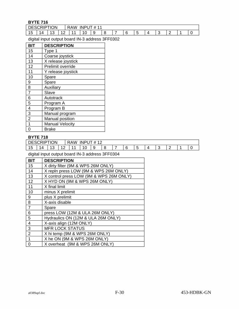
a0389apf.doc F-30 453-HDBK-GN
BYTE 716 DESCRIPTION RAW INPUT # 11 15 14 13 12 11 10 9 8 7 6 5 4 3 2 1 0 digital input output board IN-3 address 3FF0302 BIT DESCRIPTION 15 Type 1 14 Coarse joystick 13 X release joystick 12 Prelimit override 11 Y release joystick 10 Spare 9 Spare 8 Auxiliary 7 Slave 6 Autotrack 5 Program A 4 Program B 3 Manual program 2 Manual position 1 Manual Velocity 0 Brake
BYTE 718 DESCRIPTION RAW INPUT # 12 15 14 13 12 11 10 9 8 7 6 5 4 3 2 1 0 digital input output board IN-3 address 3FF0304 BIT DESCRIPTION 15 X dirty filter (9M & WPS 26M ONLY) 14 X repln press LOW (9M & WPS 26M ONLY) 13 X control press LOW (9M & WPS 26M ONLY) 12 X HYD ON (9M & WPS 26M ONLY) 11 X final limit 10 minus X prelimit 9 plus X prelimit 8 X-axis disable 7 Spare 6 press LOW (12M & ULA 26M ONLY) 5 Hydraulics ON (12M & ULA 26M ONLY) 4 X-axis align (12M ONLY) 3 MFR LOCK STATUS 2 X hi temp (9M & WPS 26M ONLY) 1 X he ON (9M & WPS 26M ONLY) 0 X overheat (9M & WPS 26M ONLY)

a0389apf.doc F-31 453-HDBK-GN
BYTE 720 DESCRIPTION RAW INPUT # 13 15 14 13 12 11 10 9 8 7 6 5 4 3 2 1 0 digital input output board IN-3 address 3FF0306 BIT DESCRIPTION 15 Y dirty filter (9M & WPS 26M ONLY) 14 Y repln press LOW (9M & WPS 26M ONLY) 13 Y control press LOW (9M & WPS 26M ONLY) 12 Y HYD ON (9M & WPS 26M ONLY) 11 Y final limit 10 minus Y prelimit 9 plus Y prelimit 8 Y-axis disable 7 Spare 6 he ON (12M & ULA 26M ONLY) 5 overheat (12M & ULA 26M ONLY) 4 Y-axis align (12M ONLY) 3 Hydraulics level LOW (12M & ULA 26M ONLY) 2 Y hi temp (9M & WPS 26M ONLY) 1 Y he ON (9M & WPS 26M ONLY) 0 Y overheat (9M & WPS 26M ONLY)
BYTE 722 DESCRIPTION RAW INPUT # 14 15 14 13 12 11 10 9 8 7 6 5 4 3 2 1 0 digital input output board IN-3 address 3FF0308 BIT DESCRIPTION 15 No Connection 14 No Connection 13 No Connection 12 No Connection 11 No Connection 10 No Connection 9 No Connection 8 No Connection 7 Spare 6 dc brake fail (12M ONLY) 5 Spare 4 Spare 3 Spare 2 Spare 1 Spare 0 Spare

a0389apf.doc F-32 453-HDBK-GN
BYTE 724 DESCRIPTION RAW INPUT # 15 15 14 13 12 11 10 9 8 7 6 5 4 3 2 1 0 digital input output board IN-4 address 3FF0400 BIT DESCRIPTION 15 Phase lock 14 FM track 13 136 Mhz (12M 14M 26M ONLY) 12 1500 (14M ONLY) 11 1700 (12M 14M 26M ONLY) 10 2200 (12M 14M 26M ONLY) 9 Acquisition (9M & ULA 26M ONLY) 8 Main (9M ONLY) 7 Auto-track system 3 selected 6 Auto-track system 2 selected 5 Auto-track system 1 selected 4 Spare 3 Spare 2 Spare 1 Spare 0 Spare
BYTE 726 DESCRIPTION RAW INPUT # 16 15 14 13 12 11 10 9 8 7 6 5 4 3 2 1 0 digital input output board IN-4 address 3FF0402 BIT DESCRIPTION 15 Phase lock 14 FM track 13 136 Mhz (12M 14M 26M ONLY) 12 1500 (14M ONLY) 11 1700 (12M 14M 26M ONLY) 10 2200 (12M 14M 26M ONLY) 9 Acquisition (9M & ULA 26M ONLY) 8 Main (9M ONLY) 7 Spare 6 Spare 5 Spare 4 Spare 3 Spare 2 Spare 1 Spare 0 Spare
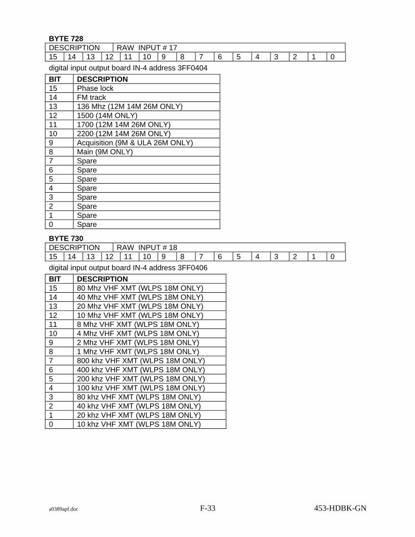
a0389apf.doc F-33 453-HDBK-GN
BYTE 728 DESCRIPTION RAW INPUT # 17 15 14 13 12 11 10 9 8 7 6 5 4 3 2 1 0 digital input output board IN-4 address 3FF0404 BIT DESCRIPTION 15 Phase lock 14 FM track 13 136 Mhz (12M 14M 26M ONLY) 12 1500 (14M ONLY) 11 1700 (12M 14M 26M ONLY) 10 2200 (12M 14M 26M ONLY) 9 Acquisition (9M & ULA 26M ONLY) 8 Main (9M ONLY) 7 Spare 6 Spare 5 Spare 4 Spare 3 Spare 2 Spare 1 Spare 0 Spare
BYTE 730 DESCRIPTION RAW INPUT # 18 15 14 13 12 11 10 9 8 7 6 5 4 3 2 1 0 digital input output board IN-4 address 3FF0406 BIT DESCRIPTION 15 80 Mhz VHF XMT (WLPS 18M ONLY) 14 40 Mhz VHF XMT (WLPS 18M ONLY) 13 20 Mhz VHF XMT (WLPS 18M ONLY) 12 10 Mhz VHF XMT (WLPS 18M ONLY) 11 8 Mhz VHF XMT (WLPS 18M ONLY) 10 4 Mhz VHF XMT (WLPS 18M ONLY) 9 2 Mhz VHF XMT (WLPS 18M ONLY) 8 1 Mhz VHF XMT (WLPS 18M ONLY) 7 800 khz VHF XMT (WLPS 18M ONLY) 6 400 khz VHF XMT (WLPS 18M ONLY) 5 200 khz VHF XMT (WLPS 18M ONLY) 4 100 khz VHF XMT (WLPS 18M ONLY) 3 80 khz VHF XMT (WLPS 18M ONLY) 2 40 khz VHF XMT (WLPS 18M ONLY) 1 20 khz VHF XMT (WLPS 18M ONLY) 0 10 khz VHF XMT (WLPS 18M ONLY)

a0389apf.doc F-34 453-HDBK-GN
BYTE 732 DESCRIPTION RAW INPUT # 19 15 14 13 12 11 10 9 8 7 6 5 4 3 2 1 0 digital input output board IN-4 address 3FF0408 BIT DESCRIPTION 15 No Connection 14 No Connection 13 No Connection 12 No Connection 11 No Connection 10 No Connection 9 No Connection 8 No Connection 7 Spare 6 Spare 5 Rcvr 6 4 Rcvr 5 3 Rcvr 4 2 Rcvr 3 1 Rcvr 2 0 Rcvr 1
BYTE 734 DESCRIPTION RAW INPUT # 20 15 14 13 12 11 10 9 8 7 6 5 4 3 2 1 0 digital input output board IN-5 address 3FF0500 BIT DESCRIPTION 15 Spare 14 Spare 13 Spare 12 CAI X sign 11 CAI X 80 Deg 10 CAI X 40 Deg 9 CAI X 20 Deg 8 CAI X 10 Deg 7 CAI X 8 Deg 6 CAI X 4 Deg 5 CAI X 2 Deg 4 CAI X 1 Deg 3 CAI X 0.8 Deg 2 CAI X 0.4 Deg 1 CAI X 0.2 Deg 0 CAI X 0.1 Deg

a0389apf.doc F-35 453-HDBK-GN
BYTE 736 DESCRIPTION RAW INPUT # 21 15 14 13 12 11 10 9 8 7 6 5 4 3 2 1 0 digital input output board IN-5 address 3FF0502 BIT DESCRIPTION 15 Spare 14 Spare 13 Spare 12 CAI Y sign 11 CAI Y 80 Deg 10 CAI Y 40 Deg 9 CAI Y 20 Deg 8 CAI Y 10 Deg 7 CAI Y 8 Deg 6 CAI Y 4 Deg 5 CAI Y 2 Deg 4 CAI Y 1 Deg 3 CAI Y 0.8 Deg 2 CAI Y 0.4 Deg 1 CAI Y 0.2 Deg 0 CAI Y 0.1 Deg
BYTE 738 DESCRIPTION RAW INPUT # 22 15 14 13 12 11 10 9 8 7 6 5 4 3 2 1 0 digital input output board IN-5 address 3FF0504 BIT DESCRIPTION 15 Spare 14 Spare 13 Spare 12 Spare 11 Spare 10 Spare 9 Spare 8 Spare 7 X Encoder Fault Code Bit 1 6 X Encoder Fault Code Bit 2 5 X Encoder Fault Code Bit 4 4 X Encoder Fault Code Bit 8 3 Y Encoder Fault Code Bit 1 2 Y Encoder Fault Code Bit 2 1 Y Encoder Fault Code Bit 4 0 Y Encoder Fault Code Bit 8

a0389apf.doc F-36 453-HDBK-GN
BYTE 740 DESCRIPTION RAW INPUT # 23 15 14 13 12 11 10 9 8 7 6 5 4 3 2 1 0 digital input output board IN-5 address 3FF0506 BIT DESCRIPTION 15 X-Minor Fault (14M ONLY) 14 Y-Minor Fault (14M ONLY) 13 X-Major Fault (14M ONLY) 12 Y-Major Fault (14M ONLY) 11 X-Rate Limit (14M ONLY) 10 Y-Rate Limit (14M ONLY) 9 X-Pre Limit (14M ONLY) 8 Y-Pre Limit (14M ONLY) 7 X-Brake Release (14M ONLY) 6 Y-Brake Release (14M ONLY) 5 X-Stowed (14M ONLY) 4 Y-Stowed (14M ONLY) 3 X-Unstowed (14M ONLY) 2 Y-Unstowed (14M ONLY) 1 Spare 0 Spare
BYTE 742 DESCRIPTION RAW INPUT # 24 15 14 13 12 11 10 9 8 7 6 5 4 3 2 1 0 digital input output board IN-5 address 3FF0508 BIT DESCRIPTION 15 No Connection 14 No Connection 13 No Connection 12 No Connection 11 No Connection 10 No Connection 9 No Connection 8 No Connection 7 Spare 6 Spare 5 Spare 4 Spare 3 Spare 2 Spare 1 Spare 0 Spare

a0389apf.doc F-37 453-HDBK-GN
BYTE 744 DESCRIPTION RAW INPUT # 25 15 14 13 12 11 10 9 8 7 6 5 4 3 2 1 0 digital input output board IN-6 address 3FF0600 BIT DESCRIPTION 15 Exciter drive on 14 Exciter search out 13 Exciter Modulation on 12 Spare 11 Spare 10 Spare 9 Spare 8 Spare 7 Spare 6 System slave source 5 Range granularity (WLPS 18M - SRE J21) 4 Range granularity (WLPS 18M - SRE J21) 3 Spare (WLPS 18M - Modulation SRE J21) 2 SBE READT (WLPS 18M - Doppler SRE J21) 1 Range Acquired (WLPS 18M - SRE J21) 0 Range Data Available (WLPS 18M - SRE J21)
BYTE 746 DESCRIPTION RAW INPUT # 26 15 14 13 12 11 10 9 8 7 6 5 4 3 2 1 0 digital input output board IN-6 address 3FF0602 BIT DESCRIPTION 15 Range data 2 to the 31 (WLPS 18M - SRE J21) 14 Range data 2 to the 30 (WLPS 18M - SRE J21) 13 Range data 2 to the 29 (WLPS 18M - SRE J21) 12 Range data 2 to the 28 (WLPS 18M - SRE J21) 11 Range data 2 to the 27 (WLPS 18M - SRE J21) 10 Range data 2 to the 26 (WLPS 18M - SRE J21) 9 Range data 2 to the 25 (WLPS 18M - SRE J21) 8 Range data 2 to the 24 (WLPS 18M - SRE J21) 7 Range data 2 to the 23 (WLPS 18M - SRE J21) 6 Range data 2 to the 22 (WLPS 18M - SRE J21) 5 Range data 2 to the 21 (WLPS 18M - SRE J21) 4 Range data 2 to the 20 (WLPS 18M - SRE J21) 3 Range data 2 to the 19 (WLPS 18M - SRE J21) 2 Range data 2 to the 18 (WLPS 18M - SRE J21) 1 Range data 2 to the 17 (WLPS 18M - SRE J21) 0 Range data 2 to the 16 (WLPS 18M - SRE J21)

a0389apf.doc F-38 453-HDBK-GN
BYTE 748 DESCRIPTION RAW INPUT # 27 15 14 13 12 11 10 9 8 7 6 5 4 3 2 1 0 digital input output board IN-6 address 3FF0604 BIT DESCRIPTION 15 Range data 2 to the 15 (WLPS 18M - SRE J21) 14 Range data 2 to the 14 (WLPS 18M - SRE J21) 13 Range data 2 to the 13 (WLPS 18M - SRE J21) 12 Range data 2 to the 12 (WLPS 18M - SRE J21) 11 Range data 2 to the 11 (WLPS 18M - SRE J21) 10 Range data 2 to the 10 (WLPS 18M - SRE J21) 9 Range data 2 to the 9 (WLPS 18M - SRE J21) 8 Range data 2 to the 8 (WLPS 18M - SRE J21) 7 Range data 2 to the 7 (WLPS 18M - SRE J21) 6 Range data 2 to the 6 (WLPS 18M - SRE J21) 5 Range data 2 to the 5 (WLPS 18M - SRE J21) 4 Range data 2 to the 4 (WLPS 18M - SRE J21) 3 Range data 2 to the 3 (WLPS 18M - SRE J21) 2 Range data 2 to the 2 (WLPS 18M - SRE J21) 1 Range data 2 to the 1 (WLPS 18M - SRE J21) 0 Range data 2 to the 0 (WLPS 18M - SRE J21)
BYTE 750 DESCRIPTION RAW INPUT # 28 15 14 13 12 11 10 9 8 7 6 5 4 3 2 1 0 digital input output board IN-6 address 3FF0606 BIT DESCRIPTION 15 Spare 14 Spare 13 Spare 12 Spare 11 AUX 1 select 10 AUX 2 select 9 AUX 3 select 8 AUX 4 select 7 AUX 5 select 6 AUX 6 select 5 OTE A/B 4 OTE-A HOLD 3 OTE-A RESET 2 OTE-B HOLD 1 OTE-B RESET 0 Spare

a0389apf.doc F-39 453-HDBK-GN
BYTE 752 DESCRIPTION RAW INPUT # 29 15 14 13 12 11 10 9 8 7 6 5 4 3 2 1 0 digital input output board IN-6 address 3FF0608 BIT DESCRIPTION 15 No Connection 14 No Connection 13 No Connection 12 No Connection 11 No Connection 10 No Connection 9 No Connection 8 No Connection 7 Spare 6 Spare 5 Spare 4 Spare 3 Spare 2 Spare 1 Spare 0 Spare
BYTE 754 DESCRIPTION RAW INPUT # 30 15 14 13 12 11 10 9 8 7 6 5 4 3 2 1 0 digital input output board IN-7 address 3FF0700 BIT DESCRIPTION 15 Selected VCO locked (WLPS 18M - SRE J21) 14 Doppler Loop Lock (WLPS 18M - SRE J21 VCO Change) 13 Spare 12 Spare 11 Spare 10 Spare 9 Doppler data 2 to the 41 (WLPS 18M - SRE J21) 8 Doppler data 2 to the 40 (WLPS 18M - SRE J21) 7 Doppler data 2 to the 39 (WLPS 18M - SRE J21) 6 Doppler data 2 to the 38 (WLPS 18M - SRE J21) 5 Doppler data 2 to the 37 (WLPS 18M - SRE J21) 4 Doppler data 2 to the 36 (WLPS 18M - SRE J21) 3 Doppler data 2 to the 35 (WLPS 18M - SRE J21) 2 Doppler data 2 to the 34 (WLPS 18M - SRE J21) 1 Doppler data 2 to the 33 (WLPS 18M - SRE J21) 0 Doppler data 2 to the 32 (WLPS 18M - SRE J21)

a0389apf.doc F-40 453-HDBK-GN
BYTE 756 DESCRIPTION RAW INPUT # 31 15 14 13 12 11 10 9 8 7 6 5 4 3 2 1 0 digital input output board IN-7 address 3FF0702 BIT DESCRIPTION 15 Doppler data 2 to the 31 (WLPS 18M - SRE J21) 14 Doppler data 2 to the 30 (WLPS 18M - SRE J21) 13 Doppler data 2 to the 29 (WLPS 18M - SRE J21) 12 Doppler data 2 to the 28 (WLPS 18M - SRE J21) 11 Doppler data 2 to the 27 (WLPS 18M - SRE J21) 10 Doppler data 2 to the 26 (WLPS 18M - SRE J21) 9 Doppler data 2 to the 25 (WLPS 18M - SRE J21) 8 Doppler data 2 to the 24 (WLPS 18M - SRE J21) 7 Doppler data 2 to the 23 (WLPS 18M - SRE J21) 6 Doppler data 2 to the 22 (WLPS 18M - SRE J21) 5 Doppler data 2 to the 21 (WLPS 18M - SRE J21) 4 Doppler data 2 to the 20 (WLPS 18M - SRE J21) 3 Doppler data 2 to the 19 (WLPS 18M - SRE J21) 2 Doppler data 2 to the 18 (WLPS 18M - SRE J21) 1 Doppler data 2 to the 17 (WLPS 18M - SRE J21) 0 Doppler data 2 to the 16 (WLPS 18M - SRE J21)
BYTE 758 DESCRIPTION RAW INPUT # 32 15 14 13 12 11 10 9 8 7 6 5 4 3 2 1 0 digital input output board IN-7 address 3FF0704 BIT DESCRIPTION 15 Doppler data 2 to the 15 (WLPS 18M - SRE J21) 14 Doppler data 2 to the 14 (WLPS 18M - SRE J21) 13 Doppler data 2 to the 13 (WLPS 18M - SRE J21) 12 Doppler data 2 to the 12 (WLPS 18M - SRE J21) 11 Doppler data 2 to the 11 (WLPS 18M - SRE J21) 10 Doppler data 2 to the 10 (WLPS 18M - SRE J21) 9 Doppler data 2 to the 9 (WLPS 18M - SRE J21) 8 Doppler data 2 to the 8 (WLPS 18M - SRE J21) 7 Doppler data 2 to the 7 (WLPS 18M - SRE J21) 6 Doppler data 2 to the 6 (WLPS 18M - SRE J21) 5 Doppler data 2 to the 5 (WLPS 18M - SRE J21) 4 Doppler data 2 to the 4 (WLPS 18M - SRE J21) 3 Doppler data 2 to the 3 (WLPS 18M - SRE J21) 2 Doppler data 2 to the 2 (WLPS 18M - SRE J21) 1 Doppler data 2 to the 1 (WLPS 18M - SRE J21) 0 Doppler data 2 to the 0 (WLPS 18M - SRE J21)

a0389apf.doc F-41 453-HDBK-GN
BYTE 760 DESCRIPTION RAW INPUT # 33 15 14 13 12 11 10 9 8 7 6 5 4 3 2 1 0 digital input output board IN-7 address 3FF0706 BIT DESCRIPTION 15 unassigned 14 unassigned 13 unassigned 12 unassigned 11 unassigned 10 unassigned 9 unassigned 8 unassigned 7 unassigned 6 unassigned 5 unassigned 4 unassigned 3 unassigned 2 unassigned 1 unassigned 0 unassigned
BYTE 762 DESCRIPTION RAW INPUT # 34 15 14 13 12 11 10 9 8 7 6 5 4 3 2 1 0 digital input output board IN-7 address 3FF0708 BIT DESCRIPTION 15 No Connection 14 No Connection 13 No Connection 12 No Connection 11 No Connection 10 No Connection 9 No Connection 8 No Connection 7 Spare 6 Spare 5 Narrow Loop Bandwidth (WLPS 18M Only) 4 Medium Loop Bandwidth (WLPS 18M Only) 3 Wide Loop Bandwidth (WLPS 18M Only) 2 Select PSK ON 1 SelectPM ON 0 SelectFM ON

a0389apf.doc F-42 453-HDBK-GN
BYTE 764 DESCRIPTION RAW INPUT # 35 15 14 13 12 11 10 9 8 7 6 5 4 3 2 1 0 digital input output board IN-8 address 3FF0800 BIT DESCRIPTION 15 Spare 14 Spare 13 Spare 12 Spare 11 Spare 10 Spare 9 Spare 8 100-MHz exciter frequency 7 80-MHz exciter frequency 6 40-MHz exciter frequency 5 20-MHz exciter frequency 4 10-MHz exciter frequency 3 8-MHz exciter frequency 2 4-MHz exciter frequency 1 2-MHz exciter frequency 0 1-MHz exciter frequency
BYTE 766 DESCRIPTION RAW INPUT # 36 15 14 13 12 11 10 9 8 7 6 5 4 3 2 1 0 digital input output board IN-8 address 3FF0802 BIT DESCRIPTION 15 800-kHz exciter frequency 14 400-kHz exciter frequency 13 200-kHz exciter frequency 12 100-kHz exciter frequency 11 80-kHz exciter frequency 10 40-kHz exciter frequency 9 20-kHz exciter frequency 8 10-kHz exciter frequency 7 8-kHz exciter frequency 6 4-kHz exciter frequency 5 2-kHz exciter frequency 4 1-kHz exciter frequency 3 800-Hz exciter frequency 2 400-Hz exciter frequency 1 200-Hz exciter frequency 0 100-Hz exciter frequency

a0389apf.doc F-43 453-HDBK-GN
BYTE 768 DESCRIPTION RAW INPUT # 37 15 14 13 12 11 10 9 8 7 6 5 4 3 2 1 0 digital input output board IN-8 address 3FF0804 BIT DESCRIPTION 15 Spare 14 Spare 13 Add time bias 12 Time bias sign 11 Spare 10 Spare 9 Time bias 20 hours 8 Time bias 10 hours 7 Time bias 8 hours 6 Time bias 4 hours 5 Time bias 2 hours 4 Time bias 1 hours 3 Spare 2 Time bias 40 minutes 1 Time bias 20 minutes 0 Time bias 10 minutes
BYTE 770 DESCRIPTION RAW INPUT # 38 15 14 13 12 11 10 9 8 7 6 5 4 3 2 1 0 digital input output board IN-8 address 3FF0806 BIT DESCRIPTION 15 Time bias 8 minutes 14 Time bias 4 minutes 13 Time bias 2 minutes 12 Time bias 1 minutes 11 Spare 10 Time bias 40 seconds 9 Time bias 20 seconds 8 Time bias 10 seconds 7 Time bias 8 seconds 6 Time bias 4 seconds 5 Time bias 2 seconds 4 Time bias 1 seconds 3 Time bias 0.8 seconds 2 Time bias 0.4 seconds 1 Time bias 0.2 seconds 0 Time bias 0.1 seconds

a0389apf.doc F-44 453-HDBK-GN
BYTE 772 DESCRIPTION RAW INPUT # 39 15 14 13 12 11 10 9 8 7 6 5 4 3 2 1 0 digital input output board IN-8 address 3FF0808 BIT DESCRIPTION 15 No Connection 14 No Connection 13 No Connection 12 No Connection 11 No Connection 10 No Connection 9 No Connection 8 No Connection 7 Spare 6 Spare 5 Spare 4 Spare 3 Spare 2 Spare 1 Spare 0 Spare
BYTE 774 DESCRIPTION RAW INPUT # 40 15 14 13 12 11 10 9 8 7 6 5 4 3 2 1 0 Analog to Digital input X Tach 1 A/D scale factor 0.0003051758
BYTE 776 DESCRIPTION RAW INPUT # 41 15 14 13 12 11 10 9 8 7 6 5 4 3 2 1 0 Analog to Digital input X Tach 2 A/D scale factor 0.0003051758
BYTE 778 DESCRIPTION RAW INPUT # 42 15 14 13 12 11 10 9 8 7 6 5 4 3 2 1 0 Analog to Digital input Y Tach 1 A/D scale factor 0.0003051758
BYTE 780 DESCRIPTION RAW INPUT # 43 15 14 13 12 11 10 9 8 7 6 5 4 3 2 1 0 Analog to Digital input Y Tach 2 A/D scale factor 0.0003051758

a0389apf.doc F-45 453-HDBK-GN
BYTE 782 DESCRIPTION RAW INPUT # 44 15 14 13 12 11 10 9 8 7 6 5 4 3 2 1 0 Analog to Digital input X Joystick A/D scale factor 0.0003051758
BYTE 784 DESCRIPTION RAW INPUT # 45 15 14 13 12 11 10 9 8 7 6 5 4 3 2 1 0 Analog to Digital input Y Joystick A/D scale factor 0.0003051758
BYTE 786 DESCRIPTION RAW INPUT # 46 15 14 13 12 11 10 9 8 7 6 5 4 3 2 1 0 Analog to Digital input X Slave Error A/D scale factor 0.0003051758
BYTE 788 DESCRIPTION RAW INPUT # 47 15 14 13 12 11 10 9 8 7 6 5 4 3 2 1 0 Analog to Digital input Y Slave Error A/D scale factor 0.0003051758
BYTE 790 DESCRIPTION RAW INPUT # 48 15 14 13 12 11 10 9 8 7 6 5 4 3 2 1 0 Analog to Digital input X RCVR 1 Error Volts A/D scale factor 0.0003051758
BYTE 792 DESCRIPTION RAW INPUT # 49 15 14 13 12 11 10 9 8 7 6 5 4 3 2 1 0 Analog to Digital input Y RCVR 1 Error Volts A/D scale factor 0.0003051758
BYTE 794 DESCRIPTION RAW INPUT # 50 15 14 13 12 11 10 9 8 7 6 5 4 3 2 1 0 Analog to Digital input X RCVR 2 Error Volts A/D scale factor 0.0003051758

a0389apf.doc F-46 453-HDBK-GN
BYTE 796 DESCRIPTION RAW INPUT # 51 15 14 13 12 11 10 9 8 7 6 5 4 3 2 1 0 Analog to Digital input Y RCVR 2 Error Volts A/D scale factor 0.0003051758
BYTE 798 DESCRIPTION RAW INPUT # 52 15 14 13 12 11 10 9 8 7 6 5 4 3 2 1 0 Analog to Digital input X RCVR 3 Error Volts A/D scale factor 0.0003051758
BYTE 800 DESCRIPTION RAW INPUT # 53 15 14 13 12 11 10 9 8 7 6 5 4 3 2 1 0 Analog to Digital input Y RCVR 3 Error Volts A/D scale factor 0.0003051758
BYTE 802 DESCRIPTION RAW INPUT # 54 15 14 13 12 11 10 9 8 7 6 5 4 3 2 1 0 Analog to Digital input RCVR 1 AGC (DBM) A/D scale factor 0.0003051758
BYTE 804 DESCRIPTION RAW INPUT # 55 15 14 13 12 11 10 9 8 7 6 5 4 3 2 1 0 Analog to Digital input RCVR 2 AGC (DBM) A/D scale factor 0.0003051758
BYTE 806 DESCRIPTION RAW INPUT # 56 15 14 13 12 11 10 9 8 7 6 5 4 3 2 1 0 Analog to Digital input RCVR 3 AGC (DBM) A/D scale factor 0.0003051758
BYTE 808 DESCRIPTION RAW INPUT # 57 15 14 13 12 11 10 9 8 7 6 5 4 3 2 1 0 Analog to Digital input Spare

a0389apf.doc F-47 453-HDBK-GN
BYTE 810 DESCRIPTION RAW INPUT # 58 15 14 13 12 11 10 9 8 7 6 5 4 3 2 1 0 Analog to Digital input +28 V DC
BYTE 812 DESCRIPTION RAW INPUT # 59 15 14 13 12 11 10 9 8 7 6 5 4 3 2 1 0 Analog to Digital input -28 V DC
BYTE 814 DESCRIPTION RAW INPUT # 60 15 14 13 12 11 10 9 8 7 6 5 4 3 2 1 0 Analog to Digital input +15 V DC (X Axis)
BYTE 816 DESCRIPTION RAW INPUT # 61 15 14 13 12 11 10 9 8 7 6 5 4 3 2 1 0 Analog to Digital input -15 V DC (X Axis)
BYTE 818 DESCRIPTION RAW INPUT # 62 15 14 13 12 11 10 9 8 7 6 5 4 3 2 1 0 Analog to Digital input +15 V DC (Y Axis)
BYTE 820 DESCRIPTION RAW INPUT # 63 15 14 13 12 11 10 9 8 7 6 5 4 3 2 1 0 Analog to Digital input -15 V DC (Y Axis)
BYTE 822 DESCRIPTION RAW INPUT # 64 15 14 13 12 11 10 9 8 7 6 5 4 3 2 1 0 Analog to Digital input +5 V DC LOGIC P/S
BYTE 824 DESCRIPTION RAW INPUT # 65 15 14 13 12 11 10 9 8 7 6 5 4 3 2 1 0 Analog to Digital input +8 V DC LOGIC P/S

a0389apf.doc F-48 453-HDBK-GN
BYTE 826 DESCRIPTION RAW INPUT # 66 15 14 13 12 11 10 9 8 7 6 5 4 3 2 1 0 Analog to Digital input +4 V DC LOGIC P/S
BYTE 828 DESCRIPTION RAW INPUT # 67 15 14 13 12 11 10 9 8 7 6 5 4 3 2 1 0 Analog to Digital input -8 V DC LOGIC P/S
BYTE 830 DESCRIPTION RAW INPUT # 68 15 14 13 12 11 10 9 8 7 6 5 4 3 2 1 0 Analog to Digital input X Yoke Pot FDBK
BYTE 832 DESCRIPTION RAW INPUT # 69 15 14 13 12 11 10 9 8 7 6 5 4 3 2 1 0 Analog to Digital input Y Yoke Pot FDBK
BYTE 834 DESCRIPTION RAW INPUT # 70 15 14 13 12 11 10 9 8 7 6 5 4 3 2 1 0 Analog to Digital input X Servo value out
BYTE 836 DESCRIPTION RAW INPUT # 71 15 14 13 12 11 10 9 8 7 6 5 4 3 2 1 0 Analog to Digital input Y Servo value out
BYTE 838 DESCRIPTION RAW INPUT # 72 15 14 13 12 11 10 9 8 7 6 5 4 3 2 1 0 Analog to Digital input A AGC MFR 1
BYTE 840 DESCRIPTION RAW INPUT # 73 15 14 13 12 11 10 9 8 7 6 5 4 3 2 1 0 Analog to Digital input B AGC MFR 1

a0389apf.doc F-49 453-HDBK-GN
BYTE 842 DESCRIPTION RAW INPUT # 74 15 14 13 12 11 10 9 8 7 6 5 4 3 2 1 0 Analog to Digital input A AGC MFR 2
BYTE 844 DESCRIPTION RAW INPUT # 75 15 14 13 12 11 10 9 8 7 6 5 4 3 2 1 0 Analog to Digital input B AGC MFR 2
BYTE 846 DESCRIPTION RAW INPUT # 76 15 14 13 12 11 10 9 8 7 6 5 4 3 2 1 0 Analog to Digital input A AGC MFR 3
BYTE 848 DESCRIPTION RAW INPUT # 77 15 14 13 12 11 10 9 8 7 6 5 4 3 2 1 0 Analog to Digital input B AGC MFR 3
BYTE 850 DESCRIPTION RAW INPUT # 78 15 14 13 12 11 10 9 8 7 6 5 4 3 2 1 0 Analog to Digital input A AGC MFR 3
BYTE 852 DESCRIPTION RAW INPUT # 79 15 14 13 12 11 10 9 8 7 6 5 4 3 2 1 0 Analog to Digital input Spare
BYTE 854 DESCRIPTION RAW INPUT # 80 15 14 13 12 11 10 9 8 7 6 5 4 3 2 1 0 Analog to Digital input Spare
BYTE 856 DESCRIPTION RAW INPUT # 81 15 14 13 12 11 10 9 8 7 6 5 4 3 2 1 0 Analog to Digital input Spare

a0389apf.doc F-50 453-HDBK-GN
BYTE 858 DESCRIPTION RAW INPUT # 82 15 14 13 12 11 10 9 8 7 6 5 4 3 2 1 0 Analog to Digital input Spare
BYTE 860 DESCRIPTION RAW INPUT # 83 15 14 13 12 11 10 9 8 7 6 5 4 3 2 1 0 Analog to Digital input Spare
BYTE 862 DESCRIPTION RAW INPUT # 84 15 14 13 12 11 10 9 8 7 6 5 4 3 2 1 0 Analog to Digital input Spare
BYTE 864 DESCRIPTION RAW INPUT # 85 15 14 13 12 11 10 9 8 7 6 5 4 3 2 1 0 Analog to Digital input Spare
BYTE 866 DESCRIPTION RAW INPUT # 86 15 14 13 12 11 10 9 8 7 6 5 4 3 2 1 0 Analog to Digital input Spare
BYTE 868 DESCRIPTION RAW INPUT # 87 15 14 13 12 11 10 9 8 7 6 5 4 3 2 1 0 Analog to Digital input Spare
BYTE 870 DESCRIPTION RAW INPUT # 88 15 14 13 12 11 10 9 8 7 6 5 4 3 2 1 0 Analog to Digital input Spare
BYTE 872 DESCRIPTION RAW INPUT # 89 15 14 13 12 11 10 9 8 7 6 5 4 3 2 1 0 Analog to Digital input Spare
BYTE 874 DESCRIPTION RAW INPUT # 90 15 14 13 12 11 10 9 8 7 6 5 4 3 2 1 0 Analog to Digital input Spare

a0389apf.doc F-51 453-HDBK-GN
BYTE 876 DESCRIPTION RAW INPUT # 91 15 14 13 12 11 10 9 8 7 6 5 4 3 2 1 0 Analog to Digital input Spare
BYTE 878 DESCRIPTION RAW INPUT # 92 15 14 13 12 11 10 9 8 7 6 5 4 3 2 1 0 Analog to Digital input Spare
BYTE 880 DESCRIPTION RAW INPUT # 93 15 14 13 12 11 10 9 8 7 6 5 4 3 2 1 0 Analog to Digital input Spare
BYTE 882 DESCRIPTION RAW INPUT # 94 15 14 13 12 11 10 9 8 7 6 5 4 3 2 1 0 Analog to Digital input Spare
BYTE 884 DESCRIPTION RAW INPUT # 95 15 14 13 12 11 10 9 8 7 6 5 4 3 2 1 0 Analog to Digital input Spare
BYTE 886 DESCRIPTION RAW INPUT # 96 15 14 13 12 11 10 9 8 7 6 5 4 3 2 1 0 Analog to Digital input Spare
BYTE 888 DESCRIPTION RAW INPUT # 97 15 14 13 12 11 10 9 8 7 6 5 4 3 2 1 0 Analog to Digital input Spare
BYTE 890 DESCRIPTION RAW INPUT # 98 15 14 13 12 11 10 9 8 7 6 5 4 3 2 1 0 Analog to Digital input Spare

a0389apf.doc F-52 453-HDBK-GN
BYTE 892 DESCRIPTION RAW INPUT # 99 15 14 13 12 11 10 9 8 7 6 5 4 3 2 1 0 Analog to Digital input Spare
BYTE 894 DESCRIPTION RAW INPUT # 100 15 14 13 12 11 10 9 8 7 6 5 4 3 2 1 0 Analog to Digital input Spare
BYTE 896 DESCRIPTION RAW INPUT # 101 15 14 13 12 11 10 9 8 7 6 5 4 3 2 1 0 Analog to Digital input Spare
BYTE 898 DESCRIPTION RAW INPUT # 102 15 14 13 12 11 10 9 8 7 6 5 4 3 2 1 0 Analog to Digital input Spare
BYTE 900 DESCRIPTION RAW INPUT # 103 15 14 13 12 11 10 9 8 7 6 5 4 3 2 1 0 Analog to Digital input Spare
BYTE 902 DESCRIPTION RAW OUTPUT # 0 15 14 13 12 11 10 9 8 7 6 5 4 3 2 1 0 digital input output board OUT-1 address 3FF1100 BIT DESCRIPTION 15 unassigned 14 Normal 13 Test 12 Computer ready 11 Computer run 10 Time bias ready 9 Default 1 frame / min indicator 8 Scan Ready 7 Spare 6 Spare 5 Spare 4 Spare 3 Spare 2 Spare 1 Spare 0 Spare

a0389apf.doc F-53 453-HDBK-GN
BYTE 904 DESCRIPTION RAW OUTPUT # 1 15 14 13 12 11 10 9 8 7 6 5 4 3 2 1 0 digital input output board OUT-1 address 3FF1102 BIT DESCRIPTION 15 Brake 14 Manual velocity 13 Manual position 12 Manual program 11 Program A 10 Program B 9 Auto track 8 Slave 7 D-S is az / el (MILA ONLY) 6 D-S ready 5 Stow 4 Coll tower 3 Spare 2 Program A -or- B ready 1 Program B ready 0 Program A ready
BYTE 906 DESCRIPTION RAW OUTPUT # 2 15 14 13 12 11 10 9 8 7 6 5 4 3 2 1 0 digital input output board OUT-1 address 3FF1104 BIT DESCRIPTION 15 X HYD on 14 X disable on 13 Spare 12 Spare 11 Spare 10 Spare 9 Spare 8 Spare 7 Y HYD on 6 Y disable on 5 Spare 4 X-angle sign 3 X-angle 80 deg 2 X-angle 40 deg 1 X-angle 20 deg 0 X-angle 10 deg

a0389apf.doc F-54 453-HDBK-GN
BYTE 908 DESCRIPTION RAW OUTPUT # 3 15 14 13 12 11 10 9 8 7 6 5 4 3 2 1 0 digital input output board OUT-1 address 3FF1106 BIT DESCRIPTION 15 X-angle 8 deg 14 X-angle 4 deg 13 X-angle 2 deg 12 X-angle 1 deg 11 X-angle 0.8 deg 10 X-angle 0.4 deg 9 X-angle 0.2 deg 8 X-angle 0.1 deg 7 X-angle 0.08 deg 6 X-angle 0.04 deg 5 X-angle 0.02 deg 4 X-angle 0.01 deg 3 X-angle 0.008 deg 2 X-angle 0.004 deg 1 X-angle 0.002 deg 0 X-angle 0.001 deg
BYTE 910 DESCRIPTION RAW OUTPUT # 4 15 14 13 12 11 10 9 8 7 6 5 4 3 2 1 0 digital input output board OUT-1 address 3FF1108 BIT DESCRIPTION 15 No Connection 14 No Connection 13 No Connection 12 No Connection 11 No Connection 10 No Connection 9 No Connection 8 No Connection 7 Spare 6 Spare 5 Spare 4 Spare 3 Spare 2 Spare 1 Spare 0 Spare

a0389apf.doc F-55 453-HDBK-GN
BYTE 912 DESCRIPTION RAW OUTPUT # 5 15 14 13 12 11 10 9 8 7 6 5 4 3 2 1 0 digital input output board OUT-2 address 3FF1200 BIT DESCRIPTION 15 Spare 14 Spare 13 Spare 12 Spare 11 Spare 10 Spare 9 Spare 8 Spare 7 Spare 6 Spare 5 Spare 4 Y-angle sign 3 Y-angle 80 deg 2 Y-angle 40 deg 1 Y-angle 20 deg 0 Y-angle 10 deg
BYTE 914 DESCRIPTION RAW OUTPUT # 6 15 14 13 12 11 10 9 8 7 6 5 4 3 2 1 0 digital input output board OUT-2 address 3FF1202 BIT DESCRIPTION 15 Y-angle 8 deg 14 Y-angle 4 deg 13 Y-angle 2 deg 12 Y-angle 1 deg 11 Y-angle 0.8 deg 10 Y-angle 0.4 deg 9 Y-angle 0.2 deg 8 Y-angle 0.1 deg 7 Y-angle 0.08 deg 6 Y-angle 0.04 deg 5 Y-angle 0.02 deg 4 Y-angle 0.01 deg 3 Y-angle 0.008 deg 2 Y-angle 0.004 deg 1 Y-angle 0.002 deg 0 Y-angle 0.001 deg

a0389apf.doc F-56 453-HDBK-GN
BYTE 916 DESCRIPTION RAW OUTPUT # 7 15 14 13 12 11 10 9 8 7 6 5 4 3 2 1 0 digital input output board OUT-2 address 3FF1204 BIT DESCRIPTION 15 RCVR LOCK (VALID TRACK) 14 LSD on 13 HSD on 12 Range ready 11 Hydraulics on 10 Spare 9 Spare 8 Spare 7 CAI X or AZ sign 6 Spare 5 CAI AZ 200 deg 4 CAI AZ 100 deg 3 CAI X or AZ 80 deg 2 CAI X or AZ 40 deg 1 CAI X or AZ 20 deg 0 CAI X or AZ 10 deg
BYTE 918 DESCRIPTION RAW OUTPUT # 8 15 14 13 12 11 10 9 8 7 6 5 4 3 2 1 0 digital input output board OUT-2 address 3FF1206 BIT DESCRIPTION 15 CAI X or AZ 8 deg 14 CAI X or AZ 4 deg 13 CAI X or AZ 2 deg 12 CAI X or AZ 1 deg 11 CAI X or AZ 0.8 deg 10 CAI X or AZ 0.4 deg 9 CAI X or AZ 0.2 deg 8 CAI X or AZ 0.1 deg 7 CAI X or AZ 0.08 deg 6 CAI X or AZ 0.04 deg 5 CAI X or AZ 0.02 deg 4 CAI X or AZ 0.01 deg 3 CAI X or AZ 0.008 deg 2 CAI X or AZ 0.004 deg 1 CAI X or AZ 0.002 deg 0 CAI X or AZ 0.001 deg

a0389apf.doc F-57 453-HDBK-GN
BYTE 920 DESCRIPTION RAW OUTPUT # 9 15 14 13 12 11 10 9 8 7 6 5 4 3 2 1 0 digital input output board OUT-2 address 3FF1208 BIT DESCRIPTION 15 No Connection 14 No Connection 13 No Connection 12 No Connection 11 No Connection 10 No Connection 9 No Connection 8 No Connection 7 Spare 6 Spare 5 Spare 4 Spare 3 Spare 2 Spare 1 Spare 0 Spare
BYTE 922 DESCRIPTION RAW OUTPUT # 10 15 14 13 12 11 10 9 8 7 6 5 4 3 2 1 0 digital input output board OUT-3 address 3FF1300 BIT DESCRIPTION 15 Spare 14 Spare 13 Spare 12 Spare 11 Spare 10 Spare 9 Spare 8 Spare 7 CAI Y or EL sign 6 Spare 5 CAI EL 200 deg 4 CAI EL 100 deg 3 CAI Y or EL 80 deg 2 CAI Y or EL 40 deg 1 CAI Y or EL 20 deg 0 CAI Y or EL 10 deg

a0389apf.doc F-58 453-HDBK-GN
BYTE 924 DESCRIPTION RAW OUTPUT # 11 15 14 13 12 11 10 9 8 7 6 5 4 3 2 1 0 digital input output board OUT-3 address 3FF1302 BIT DESCRIPTION 15 CAI Y or EL 8 deg 14 CAI Y or EL 4 deg 13 CAI Y or EL 2 deg 12 CAI Y or EL 1 deg 11 CAI Y or EL 0.8 deg 10 CAI Y or EL 0.4 deg 9 CAI Y or EL 0.2 deg 8 CAI Y or EL 0.1 deg 7 CAI Y or EL 0.08 deg 6 CAI Y or EL 0.04 deg 5 CAI Y or EL 0.02 deg 4 CAI Y or EL 0.01 deg 3 CAI Y or EL 0.008 deg 2 CAI Y or EL 0.004 deg 1 CAI Y or EL 0.002 deg 0 CAI Y or EL 0.001 deg
BYTE 926 DESCRIPTION RAW OUTPUT # 12 15 14 13 12 11 10 9 8 7 6 5 4 3 2 1 0 digital input output board OUT-3 address 3FF1304 BIT DESCRIPTION 15 Spare 14 Spare 13 Spare 12 Spare 11 Spare 10 Spare 9 Spare 8 Spare 7 Spare 6 Spare 5 Spare 4 Spare 3 Spare 2 Spare 1 Spare 0 Spare
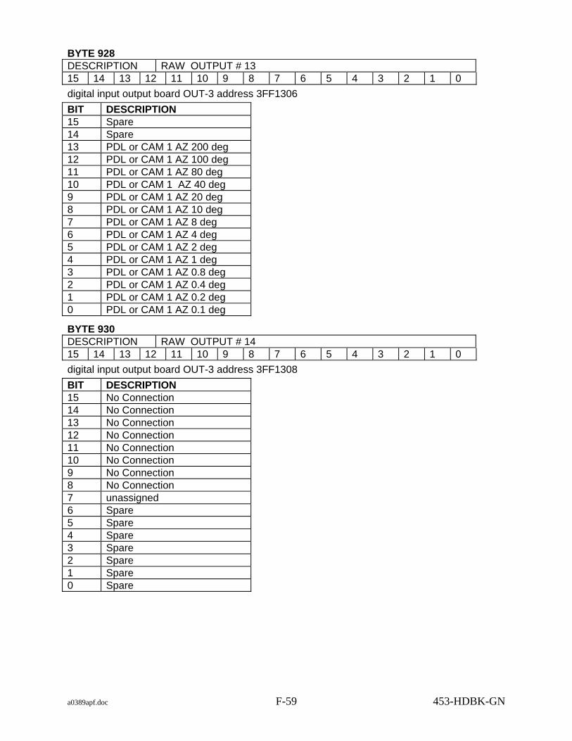
a0389apf.doc F-59 453-HDBK-GN
BYTE 928 DESCRIPTION RAW OUTPUT # 13 15 14 13 12 11 10 9 8 7 6 5 4 3 2 1 0 digital input output board OUT-3 address 3FF1306 BIT DESCRIPTION 15 Spare 14 Spare 13 PDL or CAM 1 AZ 200 deg 12 PDL or CAM 1 AZ 100 deg 11 PDL or CAM 1 AZ 80 deg 10 PDL or CAM 1 AZ 40 deg 9 PDL or CAM 1 AZ 20 deg 8 PDL or CAM 1 AZ 10 deg 7 PDL or CAM 1 AZ 8 deg 6 PDL or CAM 1 AZ 4 deg 5 PDL or CAM 1 AZ 2 deg 4 PDL or CAM 1 AZ 1 deg 3 PDL or CAM 1 AZ 0.8 deg 2 PDL or CAM 1 AZ 0.4 deg 1 PDL or CAM 1 AZ 0.2 deg 0 PDL or CAM 1 AZ 0.1 deg
BYTE 930 DESCRIPTION RAW OUTPUT # 14 15 14 13 12 11 10 9 8 7 6 5 4 3 2 1 0 digital input output board OUT-3 address 3FF1308 BIT DESCRIPTION 15 No Connection 14 No Connection 13 No Connection 12 No Connection 11 No Connection 10 No Connection 9 No Connection 8 No Connection 7 unassigned 6 Spare 5 Spare 4 Spare 3 Spare 2 Spare 1 Spare 0 Spare

a0389apf.doc F-60 453-HDBK-GN
BYTE 932 DESCRIPTION RAW OUTPUT # 15 15 14 13 12 11 10 9 8 7 6 5 4 3 2 1 0 digital input output board OUT-4 address 3FF1400 BIT DESCRIPTION 15 PDL or CAM 1 EL sign 14 Spare 13 Spare 12 Spare 11 PDL or CAM 1 EL 80 deg 10 PDL or CAM 1 EL 40 deg 9 PDL or CAM 1 EL 20 deg 8 PDL or CAM 1 EL 10 deg 7 PDL or CAM 1 EL 8 deg 6 PDL or CAM 1 EL 4 deg 5 PDL or CAM 1 EL 2 deg 4 PDL or CAM 1 EL 1 deg 3 PDL or CAM 1 EL 0.8 deg 2 PDL or CAM 1 EL 0.4 deg 1 PDL or CAM 1 EL 0.2 deg 0 PDL or CAM 1 EL 0.1 deg
BYTE 934 DESCRIPTION RAW OUTPUT # 16 15 14 13 12 11 10 9 8 7 6 5 4 3 2 1 0 digital input output board OUT-4 address 3FF1402 BIT DESCRIPTION 15 Spare 14 Spare 13 CAM 2 AZ 200 deg 12 CAM 2 AZ 100 deg 11 CAM 2 AZ 80 deg 10 CAM 2 AZ 40 deg 9 CAM 2 AZ 20 deg 8 CAM 2 AZ 10 deg 7 CAM 2 AZ 8 deg 6 CAM 2 AZ 4 deg 5 CAM 2 AZ 2 deg 4 CAM 2 AZ 1 deg 3 CAM 2 AZ 0.8 deg 2 CAM 2 AZ 0.4 deg 1 CAM 2 AZ 0.2 deg 0 CAM 2 AZ 0.1 deg

a0389apf.doc F-61 453-HDBK-GN
BYTE 936 DESCRIPTION RAW OUTPUT # 17 15 14 13 12 11 10 9 8 7 6 5 4 3 2 1 0 digital input output board OUT-4 address 3FF1404 BIT DESCRIPTION 15 CAM 2 EL sign 14 Spare 13 Spare 12 Spare 11 CAM 2 EL 80 deg 10 CAM 2 EL 40 deg 9 CAM 2 EL 20 deg 8 CAM 2 EL 10 deg 7 CAM 2 EL 8 deg 6 CAM 2 EL 4 deg 5 CAM 2 EL 2 deg 4 CAM 2 EL 1 deg 3 CAM 2 EL 0.8 deg 2 CAM 2 EL 0.4 deg 1 CAM 2 EL 0.2 deg 0 CAM 2 EL 0.1 deg
BYTE 938 DESCRIPTION RAW OUTPUT # 18 15 14 13 12 11 10 9 8 7 6 5 4 3 2 1 0 digital input output board OUT-4 address 3FF1406 BIT DESCRIPTION 15 AUX 1 READY 14 AUX 2 READY 13 AUX 3 READY 12 AUX 4 READY 11 AUX 5 READY 10 AUX 6 READY 9 OTE-A READY 8 D / O HOLD A 7 OTE-B READY 6 D / O HOLD B 5 Spare 4 Spare 3 Spare 2 Spare 1 Spare 0 Spare

a0389apf.doc F-62 453-HDBK-GN
BYTE 940 DESCRIPTION RAW OUTPUT # 19 15 14 13 12 11 10 9 8 7 6 5 4 3 2 1 0 digital input output board OUT-4 address 3FF1408 BIT DESCRIPTION 15 No Connection 14 No Connection 13 No Connection 12 No Connection 11 No Connection 10 No Connection 9 No Connection 8 No Connection 7 Spare 6 Spare 5 Spare 4 Spare 3 Spare 2 Spare 1 Spare 0 Spare
BYTE 942 DESCRIPTION RAW OUTPUT # 20 15 14 13 12 11 10 9 8 7 6 5 4 3 2 1 0 digital input output board OUT-5 address 3FF1500 BIT DESCRIPTION 15 Spare 14 Spare 13 Spare AZ 200 Deg 12 Spare AZ 100 Deg 11 Spare AZ 80 Deg 10 Spare AZ 40 Deg 9 Spare AZ 20 Deg 8 Spare AZ 10 Deg 7 Spare AZ 8 Deg 6 Spare AZ 4 Deg 5 Spare AZ 2 Deg 4 Spare AZ 1 Deg 3 Spare AZ 0.8 Deg 2 Spare AZ 0.4 Deg 1 Spare AZ 0.2 Deg 0 Spare AZ 0.1 Deg

a0389apf.doc F-63 453-HDBK-GN
BYTE 944 DESCRIPTION RAW OUTPUT # 21 15 14 13 12 11 10 9 8 7 6 5 4 3 2 1 0 digital input output board OUT-5 address 3FF1502 BIT DESCRIPTION 15 Spare EL sign 14 Spare 13 Spare 12 Spare 11 Spare EL 80 Deg 10 Spare EL 40 Deg 9 Spare EL 20 Deg 8 Spare EL 10 Deg 7 Spare EL 8 Deg 6 Spare EL 4 Deg 5 Spare EL 2 Deg 4 Spare EL 1 Deg 3 Spare EL 0.8 Deg 2 Spare EL 0.4 Deg 1 Spare EL 0.2 Deg 0 Spare EL 0.1 Deg
BYTE 946 DESCRIPTION RAW OUTPUT # 22 15 14 13 12 11 10 9 8 7 6 5 4 3 2 1 0 digital input output board OUT-5 address 3FF1504 BIT DESCRIPTION 15 Spare 14 Spare 13 Spare 12 Spare 11 Spare 10 Spare 9 Spare 8 Spare 7 Spare 6 Spare 5 Spare 4 Spare 3 Spare 2 Spare 1 Spare 0 Spare
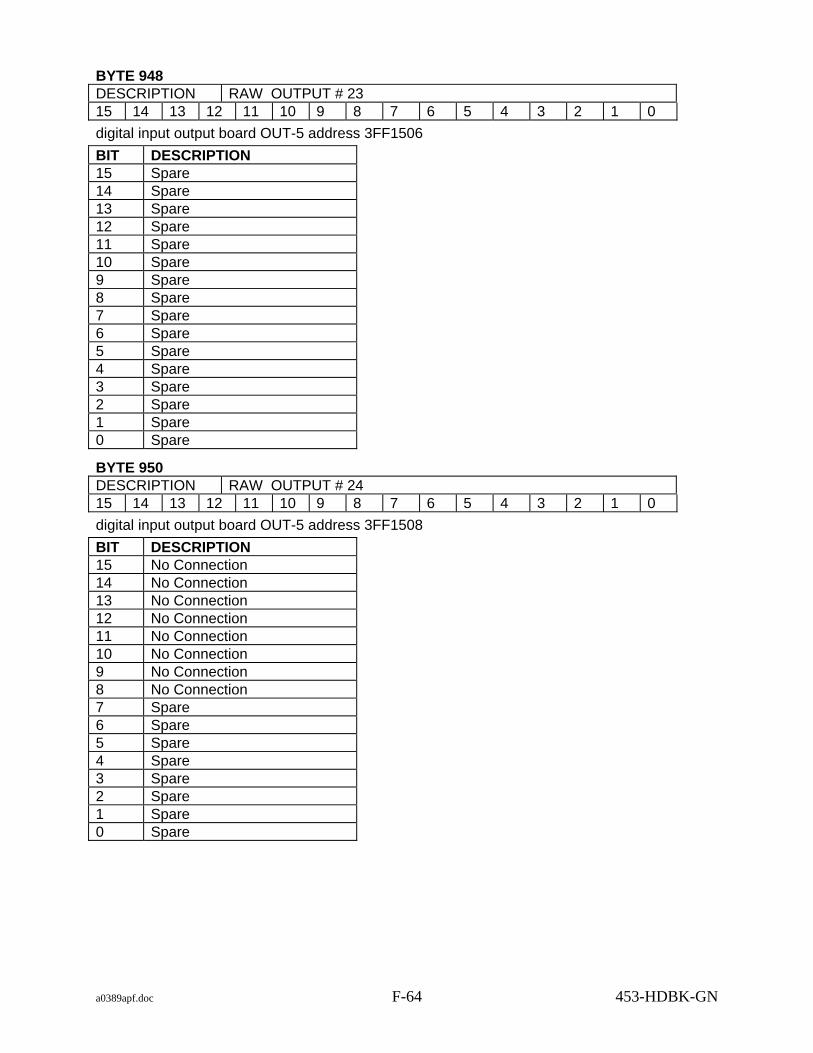
a0389apf.doc F-64 453-HDBK-GN
BYTE 948 DESCRIPTION RAW OUTPUT # 23 15 14 13 12 11 10 9 8 7 6 5 4 3 2 1 0 digital input output board OUT-5 address 3FF1506 BIT DESCRIPTION 15 Spare 14 Spare 13 Spare 12 Spare 11 Spare 10 Spare 9 Spare 8 Spare 7 Spare 6 Spare 5 Spare 4 Spare 3 Spare 2 Spare 1 Spare 0 Spare
BYTE 950 DESCRIPTION RAW OUTPUT # 24 15 14 13 12 11 10 9 8 7 6 5 4 3 2 1 0 digital input output board OUT-5 address 3FF1508 BIT DESCRIPTION 15 No Connection 14 No Connection 13 No Connection 12 No Connection 11 No Connection 10 No Connection 9 No Connection 8 No Connection 7 Spare 6 Spare 5 Spare 4 Spare 3 Spare 2 Spare 1 Spare 0 Spare
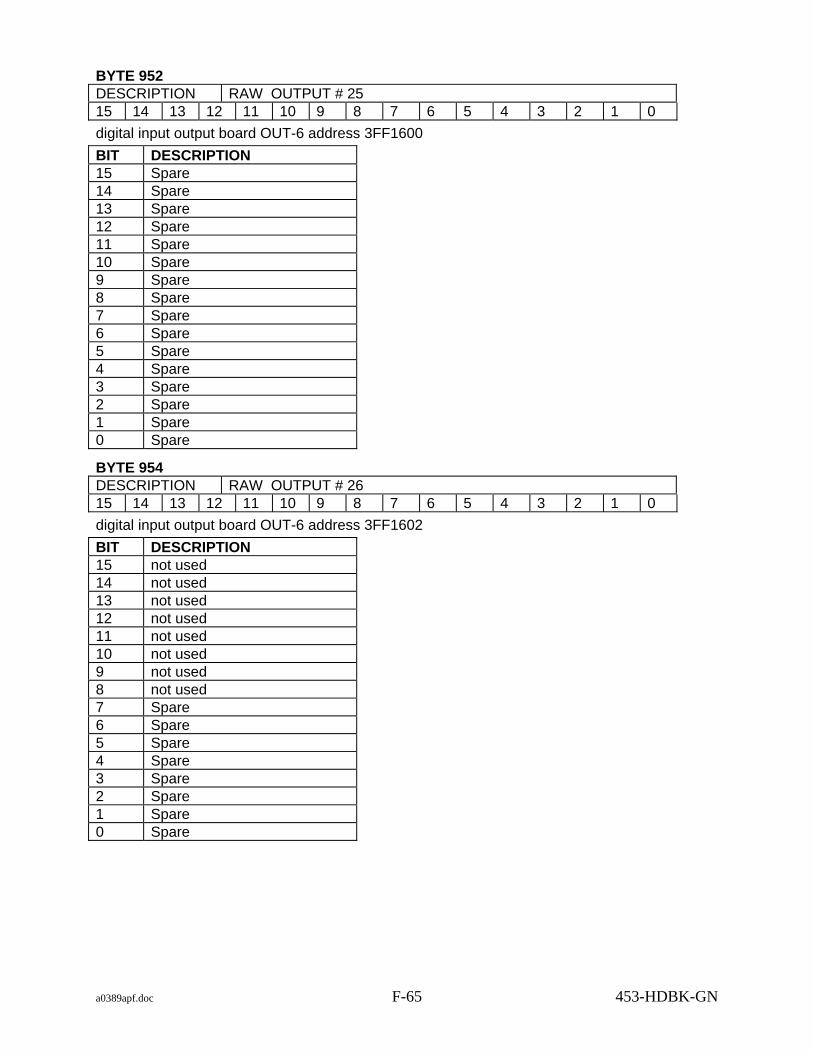
a0389apf.doc F-65 453-HDBK-GN
BYTE 952 DESCRIPTION RAW OUTPUT # 25 15 14 13 12 11 10 9 8 7 6 5 4 3 2 1 0 digital input output board OUT-6 address 3FF1600 BIT DESCRIPTION 15 Spare 14 Spare 13 Spare 12 Spare 11 Spare 10 Spare 9 Spare 8 Spare 7 Spare 6 Spare 5 Spare 4 Spare 3 Spare 2 Spare 1 Spare 0 Spare
BYTE 954 DESCRIPTION RAW OUTPUT # 26 15 14 13 12 11 10 9 8 7 6 5 4 3 2 1 0 digital input output board OUT-6 address 3FF1602 BIT DESCRIPTION 15 not used 14 not used 13 not used 12 not used 11 not used 10 not used 9 not used 8 not used 7 Spare 6 Spare 5 Spare 4 Spare 3 Spare 2 Spare 1 Spare 0 Spare

a0389apf.doc F-66 453-HDBK-GN
BYTE 956 DESCRIPTION RAW OUTPUT # 27 15 14 13 12 11 10 9 8 7 6 5 4 3 2 1 0 digital input output board OUT-6 address 3FF1604 BIT DESCRIPTION 15 not used 14 not used 13 X D/S 180 Deg (sign) 12 X D/S 90 Deg 11 X D/S 45 Deg 10 X D/S 22.5 Deg 9 X D/S 11.25 Deg 8 X D/S 5.625 Deg 7 X D/S 2.8125 Deg 6 X D/S 1.40625 Deg 5 X D/S 0.703125 Deg 4 X D/S 0.3515625 Deg 3 X D/S 0.1757812 Deg 2 X D/S 0.0878906 Deg 1 X D/S 0.0439453 Deg 0 X D/S 0.0219727 Deg
BYTE 958 DESCRIPTION RAW OUTPUT # 28 15 14 13 12 11 10 9 8 7 6 5 4 3 2 1 0 digital input output board OUT-6 address 3FF1606 BIT DESCRIPTION 15 not used 14 not used 13 Y D/S 180 Deg (sign) 12 Y D/S 90 Deg 11 Y D/S 45 Deg 10 Y D/S 22.5 Deg 9 Y D/S 11.25 Deg 8 Y D/S 5.625 Deg 7 Y D/S 2.8125 Deg 6 Y D/S 1.40625 Deg 5 Y D/S 0.703125 Deg 4 Y D/S 0.3515625 Deg 3 Y D/S 0.1757812 Deg 2 Y D/S 0.0878906 Deg 1 Y D/S 0.0439453 Deg 0 Y D/S 0.0219727 Deg

a0389apf.doc F-67 453-HDBK-GN
BYTE 960 DESCRIPTION RAW OUTPUT # 29 15 14 13 12 11 10 9 8 7 6 5 4 3 2 1 0 digital input output board OUT-6 address 3FF1608 BIT DESCRIPTION 15 No Connection 14 No Connection 13 No Connection 12 No Connection 11 No Connection 10 No Connection 9 No Connection 8 No Connection 7 Not used 6 Not used 5 Not used 4 Not used 3 Not used 2 Not used 1 Not used 0 Not used
BYTE 962 DESCRIPTION RAW OUTPUT # 30 15 14 13 12 11 10 9 8 7 6 5 4 3 2 1 0 X drive signal Digital to analog output A/D scale factor 0.0003051758
BYTE 964 DESCRIPTION RAW OUTPUT # 31 15 14 13 12 11 10 9 8 7 6 5 4 3 2 1 0 Y drive signal Digital to analog output A/D scale factor 0.0003051758
BYTE 966 DESCRIPTION RAW OUTPUT # 32 15 14 13 12 11 10 9 8 7 6 5 4 3 2 1 0 X program error Digital to analog output A/D scale factor 0.0003051758
BYTE 968 DESCRIPTION RAW OUTPUT # 33 15 14 13 12 11 10 9 8 7 6 5 4 3 2 1 0 Y program error Digital to analog output A/D scale factor 0.0003051758

a0389apf.doc F-68 453-HDBK-GN
BYTE 970 DESCRIPTION RAW OUTPUT # 34 15 14 13 12 11 10 9 8 7 6 5 4 3 2 1 0 X program error secondary Digital to analog output A/D scale factor 0.0003051758
BYTE 972 DESCRIPTION RAW OUTPUT # 35 15 14 13 12 11 10 9 8 7 6 5 4 3 2 1 0 Y program error secondary Digital to analog output A/D scale factor 0.0003051758
BYTE 974 DESCRIPTION RAW OUTPUT # 36 15 14 13 12 11 10 9 8 7 6 5 4 3 2 1 0 Spare Digital to analog output
BYTE 976 DESCRIPTION RAW OUTPUT # 37 15 14 13 12 11 10 9 8 7 6 5 4 3 2 1 0 Spare Digital to analog output
BYTE 978 - 1198 DESCRIPTION SPARE (221) 7 6 5 4 3 2 1 0
BYTE 1199 DESCRIPTION DELOG USAGE 7 6 5 4 3 2 1 0 NOTE: This byte is used by the delog software in the STPS

a0389apf.doc F-69 453-HDBK-GN
F.2 Static System Status Tape: Block Type 2
F.2.1 RTPS
F.2.1.1 Bytes 0 to 1719 The size of each tape block is 12000 bytes.
BYTE 0 DESCRIPTION TAPE BLOCK SEQUENCE COUNT 15 14 13 12 11 10 9 8 7 6 5 4 3 2 1 0
BYTE 2 DESCRIPTION TAPE BLOCK TYPE 7 6 5 4 3 2 1 0 Static System Status 2
BYTE 3 DESCRIPTION SYSTEM ID 7 6 5 4 3 2 1 0 1 = RTPS 2 = STPS 3 = DSTPS
BYTE 4 DESCRIPTION ANTENNA GEO 7 6 5 4 3 2 1 0 1 = AZ EL 2 = X Y 3 = X Y PRIME
BYTE 5 DESCRIPTION VALID RECORD 7 6 5 4 3 2 1 0 1 = VALID 0 = INVALID
BYTE 6 DESCRIPTION REAL TIME 15 14 13 12 11 10 9 8 7 6 5 4 3 2 1 0
day of year
15 14 13 12 11 10 9 8 7 6 5 4 3 2 1 0 31 30 29 28 27 26 25 24 23 22 21 20 19 18 17 16
millisecs of day
15 14 13 12 11 10 9 8 7 6 5 4 3 2 1 0 microsecs of millisecs
15 14 13 12 11 10 9 8 7 6 5 4 3 2 1 0 year

a0389apf.doc F-70 453-HDBK-GN
BYTE 16 DESCRIPTION VALID MESSAGE FLAGS 15 14 13 12 11 10 9 8 7 6 5 4 3 2 1 0 31 30 29 28 27 26 25 24 23 22 21 20 19 18 17 16 Bit set to 1 = message valid in this record. INPUT
Bit Msg Type Bit Msg Type 0 IRV A 1 OTE A 2 LRV A 3 IIRV A 4 NORAD A 5 MDDF A 6 LTAS A 7 INP A 8 MANUAL 9 IRV B
10 OTE B 11 LRV B 12 IIRV B 13 NORAD B 14 MDDF B 15 LTAS B 16 INP B 17 BROUWER A 18 BROUWER B 19 EPV A 20 EPV B
OUTPUT Bit Msg Type Bit Msg Type 21 MDDF A 22 MDDF B 23 LTAS A 24 LTAS B 25 NORAD 26 46 CHAR 28 IRV A 29 IRV B
BYTE 20 DESCRIPTION IRV A MESSAGE FROM OTE OUTPUT 7 6 5 4 3 2 1 0 Up to 850 bytes (see IRV description for format)
BYTE 870 DESCRIPTION IRV B MESSAGE FROM OTE OUTPUT 7 6 5 4 3 2 1 0 Up to 850 bytes (see IRV description for format)
F.2.1.2 CURRENT ACQUISITION DATA MESSAGES
BYTE 1720 DESCRIPTION IRV A 7 6 5 4 3 2 1 0 Up to 850 bytes (see IRV description for format)
BYTE 2530 DESCRIPTION IRV B 7 6 5 4 3 2 1 0 Up to 850 bytes (see IRV description for format) BYTE 3380

a0389apf.doc F-71 453-HDBK-GN
DESCRIPTION IIRV A 7 6 5 4 3 2 1 0 Up to 500 bytes (see IIRV description for format)
BYTE 3880 DESCRIPTION IIRV B 7 6 5 4 3 2 1 0 Up to 500 bytes (see IIRV description for format)
BYTE 4380 DESCRIPTION INP A 7 6 5 4 3 2 1 0 Up to 2500 bytes (see INP description for format)
BYTE 6880 DESCRIPTION INP B 7 6 5 4 3 2 1 0 Up to 2500 bytes (see INP description for format)
BYTE 9380 DESCRIPTION NORAD A 7 6 5 4 3 2 1 0 Up to 500 bytes (see NORAD description for format)
BYTE 9880 DESCRIPTION NORAD B 7 6 5 4 3 2 1 0 Up to 500 bytes (see NORAD description for format)
BYTE 10380 DESCRIPTION LRV A 7 6 5 4 3 2 1 0 Up to 500 bytes IIRV derived from LTAS frame (see IIRV description for format)
BYTE 10880 DESCRIPTION LRV B 7 6 5 4 3 2 1 0 Up to 500 bytes IIRV derived from LTAS frame (see IIRV description for format)

a0389apf.doc F-72 453-HDBK-GN
F.2.1.3 CPU STATUS
BYTE 11380 DESCRIPTION MP PROGRAM NAME 7 6 5 4 3 2 1 0 Up to 20 bytes of ASCII characters
BYTE 11400 DESCRIPTION MP PROGRAM VERSION 7 6 5 4 3 2 1 0 Up to 20 bytes of ASCII characters
BYTE 11420 DESCRIPTION ORBITAL PROCESSOR PROGRAM NAME 7 6 5 4 3 2 1 0 Up to 20 bytes of ASCII characters
BYTE 11440 DESCRIPTION ORBITAL PROCESSOR PROGRAM VERSION 7 6 5 4 3 2 1 0 Up to 20 bytes of ASCII characters
BYTE 11460 DESCRIPTION MAIN PROCESSOR MEMORY STATUS 7 6 5 4 3 2 1 0 1 = GOOD 0 = BAD
BYTE 11461 DESCRIPTION ORBITAL PROCESSOR MEMORY STATUS 7 6 5 4 3 2 1 0 1 = GOOD 0 = BAD
F.2.1.4 SYSTEM UNIQUE STATUS
BYTE 11462 DESCRIPTION CDSG SWITCH STATES 7 6 5 4 3 2 1 0 Switch 0 not recorded
BYTE 11463 DESCRIPTION CDSG SWITCH STATES 7 6 5 4 3 2 1 0 Switch 1 not recorded
BYTE 11464 DESCRIPTION CDSG SWITCH STATES 7 6 5 4 3 2 1 0 1 = SELECTED 0 = DESELECTED Switch 2 recorded (Select IRV A Designate Source)

a0389apf.doc F-73 453-HDBK-GN
BYTE 11465 DESCRIPTION CDSG SWITCH STATES 7 6 5 4 3 2 1 0 1 = SELECTED 0 = DESELECTED Switch 3 recorded (Select OTE A Designate Source)
BYTE 11466 DESCRIPTION CDSG SWITCH STATES 7 6 5 4 3 2 1 0 1 = SELECTED 0 = DESELECTED Switch 4 recorded (Select LRV A Designate Source)
BYTE 11467 DESCRIPTION CDSG SWITCH STATES 7 6 5 4 3 2 1 0 1 = SELECTED 0 = DESELECTED Switch 5 recorded (Select IIRV A Designate Source)
BYTE 11468 DESCRIPTION CDSG SWITCH STATES 7 6 5 4 3 2 1 0 1 = SELECTED 0 = DESELECTED Switch 6 recorded (Select NORAD A Designate Source)
BYTE 11469 DESCRIPTION CDSG SWITCH STATES 7 6 5 4 3 2 1 0 1 = SELECTED 0 = DESELECTED Switch 7 recorded (Select MDDF A Designate Source)
BYTE 11470 DESCRIPTION CDSG SWITCH STATES 7 6 5 4 3 2 1 0 1 = SELECTED 0 = DESELECTED Switch 8 recorded (Select LTAS A Designate Source)
BYTE 11471 DESCRIPTION CDSG SWITCH STATES 7 6 5 4 3 2 1 0 1 = SELECTED 0 = DESELECTED Switch 9 recorded (Select INP A Designate Source)
BYTE 11472 DESCRIPTION CDSG SWITCH STATES 7 6 5 4 3 2 1 0 Switch 10 not recorded

a0389apf.doc F-74 453-HDBK-GN
BYTE 11473 DESCRIPTION CDSG SWITCH STATES 7 6 5 4 3 2 1 0 1 = SELECTED 0 = DESELECTED Switch 11 recorded (Select MANUAL TABLE Designate Source)
BYTE 11474 DESCRIPTION CDSG SWITCH STATES 7 6 5 4 3 2 1 0 Switch 12 not recorded
BYTE 11475 DESCRIPTION CDSG SWITCH STATES 7 6 5 4 3 2 1 0 1 = SELECTED 0 = DESELECTED Switch 13 recorded (Select IRV B Designate Source)
BYTE 11476 DESCRIPTION CDSG SWITCH STATES 7 6 5 4 3 2 1 0 1 = SELECTED 0 = DESELECTED Switch 14 recorded (Select OTE B Designate Source)
BYTE 11477 DESCRIPTION CDSG SWITCH STATES 7 6 5 4 3 2 1 0 1 = SELECTED 0 = DESELECTED Switch 15 recorded (Select LRV B Designate Source)
BYTE 11478 DESCRIPTION CDSG SWITCH STATES 7 6 5 4 3 2 1 0 1 = SELECTED 0 = DESELECTED Switch 16 recorded (Select IIRV B Designate Source)
BYTE 11479 DESCRIPTION CDSG SWITCH STATES 7 6 5 4 3 2 1 0 1 = SELECTED 0 = DESELECTED Switch 17 recorded (Select NORAD B Designate Source)
BYTE 11480 DESCRIPTION CDSG SWITCH STATES 7 6 5 4 3 2 1 0 1 = SELECTED 0 = DESELECTED Switch 18 recorded (Select MDDF B Designate Source)

a0389apf.doc F-75 453-HDBK-GN
BYTE 11481 DESCRIPTION CDSG SWITCH STATES 7 6 5 4 3 2 1 0 1 = SELECTED 0 = DESELECTED Switch 19 recorded (Select LTAS B Designate Source)
BYTE 11482 DESCRIPTION CDSG SWITCH STATES 7 6 5 4 3 2 1 0 1 = SELECTED 0 = DESELECTED Switch 20 recorded (Select INP B Designate Source)
BYTE 11483 - 11492 DESCRIPTION CDSG SWITCH STATES 7 6 5 4 3 2 1 0 Switches 21 - 30 not recorded
BYTE 11493 DESCRIPTION CDSG SWITCH STATES 7 6 5 4 3 2 1 0 1 = SELECTED 0 = DESELECTED Switch 31 recorded (Select SLEW Designate Source)
BYTE 11494 - 11585 DESCRIPTION CDSG SWITCH STATES 7 6 5 4 3 2 1 0 Switches 32 - 123 not recorded
BYTE 11586 DESCRIPTION CDSG SWITCH STATES 7 6 5 4 3 2 1 0 1 = ON 0 = OFF Switch 124 recorded (SYSTEM STATUS)
BYTES 11587 - 11592 DESCRIPTION CDSG SWITCH STATES 7 6 5 4 3 2 1 0 Switches 125 - 130 not recorded
BYTE 11593 DESCRIPTION CDSG SWITCH STATES 7 6 5 4 3 2 1 0 1 = A 0 = B Switch 131 recorded (OTE SELECT Switch Position)
BYTE 11594 DESCRIPTION CDSG SWITCH STATES 7 6 5 4 3 2 1 0 Switch 132 not recorded

a0389apf.doc F-76 453-HDBK-GN
BYTE 11595 DESCRIPTION CDSG SWITCH STATES 7 6 5 4 3 2 1 0 1 = ON 0 = OFF Switch 133 recorded (NOR SPLINE)
BYTES 11596 - 11600 DESCRIPTION CDSG SWITCH STATES 7 6 5 4 3 2 1 0 Switches 134 - 138 not recorded
BYTE 11601 DESCRIPTION CDSG SWITCH STATES 7 6 5 4 3 2 1 0 1 = GMT SELECTED
0 = SIM SELECTED
Switch 139 recorded (GMT Time or SIM Time Switch Position)
BYTE 11602 DESCRIPTION CDSG SWITCH STATES 7 6 5 4 3 2 1 0 Switch 140 not recorded
BYTE 11603 DESCRIPTION CDSG SWITCH STATES 7 6 5 4 3 2 1 0 Switch 141 not recorded
BYTE 11604 DESCRIPTION CDSG SWITCH STATES 7 6 5 4 3 2 1 0 1 = ON 0 = OFF Switch 142 recorded (High Speed DATA DOD)
BYTE 11605 DESCRIPTION CDSG SWITCH STATES 7 6 5 4 3 2 1 0 1 = ON 0 = OFF Switch 143 recorded (PLUNGE SELECT)
BYTE 11606 DESCRIPTION CDSG SWITCH STATES 7 6 5 4 3 2 1 0 1 = RECORD SELECTED
0 = PLAYBACK SELECTED
Switch 144 recorded (RECORD / PLAYBACK MODE Switch Position)
BYTES 11607 - 11717 DESCRIPTION CDSG SWITCH STATES 7 6 5 4 3 2 1 0 Switches 145 - 255 not recorded BYTE 11718

a0389apf.doc F-77 453-HDBK-GN
DESCRIPTION SPARE (30) (RESERVED FOR STPS) 7 6 5 4 3 2 1 0 30 bytes
BYTES 11748 - 11999 DESCRIPTION SPARE 7 6 5 4 3 2 1 0
F.2.2 STPS
F.2.2.1 Bytes 0 to 1719 The size of each tape block is 12000 bytes.
BYTE 0 DESCRIPTION TAPE BLOCK SEQUENCE COUNT 15 14 13 12 11 10 9 8 7 6 5 4 3 2 1 0
BYTE 2 DESCRIPTION TAPE BLOCK TYPE 7 6 5 4 3 2 1 0 Static System Status 2
BYTE 3 DESCRIPTION SYSTEM ID 7 6 5 4 3 2 1 0 1 = RTPS 2 = STPS 3 = DSTPS
BYTE 4 DESCRIPTION ANTENNA GEO 7 6 5 4 3 2 1 0 1 = AZ EL 2 = X Y 3 = X Y PRIME
BYTE 5 DESCRIPTION VALID RECORD 7 6 5 4 3 2 1 0 1 = VALID 0 = INVALID
BYTE 6 DESCRIPTION REAL TIME 15 14 13 12 11 10 9 8 7 6 5 4 3 2 1 0
day of year
15 14 13 12 11 10 9 8 7 6 5 4 3 2 1 0 31 30 29 28 27 26 25 24 23 22 21 20 19 18 17 16
millisecs of day
15 14 13 12 11 10 9 8 7 6 5 4 3 2 1 0 microsecs of millisecs
15 14 13 12 11 10 9 8 7 6 5 4 3 2 1 0 year

a0389apf.doc F-78 453-HDBK-GN
BYTE 16 DESCRIPTION VALID MESSAGE FLAGS 15 14 13 12 11 10 9 8 7 6 5 4 3 2 1 0 31 30 29 28 27 26 25 24 23 22 21 20 19 18 17 16 Bit set to 1 = message valid in this record. INPUT
Bit Msg Type Bit Msg Type 0 IRV A 1 OTE A 2 LRV A 3 IIRV A 4 NORAD A 5 MDDF A 6 LTAS A 7 INP A 8 MANUAL 9 IRV B
10 OTE B 11 LRV B 12 IIRV B 13 NORAD B 14 MDDF B 15 LTAS B 16 INP B 17 BROUWER A 18 BROUWER B 19 EPV A 20 EPV B
OUTPUT Bit Msg Type Bit Msg Type 21 MDDF A 22 MDDF B 23 LTAS A 24 LTAS B 25 NORAD 26 46 CHAR 27 UTDF 28 IRV A 29 IRV B
BYTE 20 DESCRIPTION IRV A MESSAGE FROM OTE OUTPUT 7 6 5 4 3 2 1 0 Up to 850 bytes (see IRV description for format) BYTE 870 DESCRIPTION IRV B MESSAGE FROM OTE OUTPUT 7 6 5 4 3 2 1 0 Up to 850 bytes (see IRV description for format)
F.2.2.2 CURRENT ACQUISITION DATA MESSAGES
BYTE 1720 DESCRIPTION IRV A 7 6 5 4 3 2 1 0 Up to 850 bytes (see IRV description for format)
BYTE 2530 DESCRIPTION IRV B 7 6 5 4 3 2 1 0 Up to 850 bytes (see IRV description for format) BYTE 3380

a0389apf.doc F-79 453-HDBK-GN
DESCRIPTION IIRV A 7 6 5 4 3 2 1 0 Up to 500 bytes (see IIRV description for format)
BYTE 3880 DESCRIPTION IIRV B 7 6 5 4 3 2 1 0 Up to 500 bytes (see IIRV description for format)
BYTE 4380 DESCRIPTION INP A 7 6 5 4 3 2 1 0 Up to 2500 bytes (see INP description for format)
BYTE 6880 DESCRIPTION INP B 7 6 5 4 3 2 1 0 Up to 2500 bytes (see INP description for format)
BYTE 9380 DESCRIPTION NORAD A 7 6 5 4 3 2 1 0 Up to 500 bytes (see NORAD description for format)
BYTE 9880 DESCRIPTION NORAD B 7 6 5 4 3 2 1 0 Up to 500 bytes (see NORAD description for format)
BYTE 10380 DESCRIPTION LRV A 7 6 5 4 3 2 1 0 Up to 500 bytes IIRV derived from LTAS frame (see IIRV description for format)
BYTE 10880 DESCRIPTION LRV B 7 6 5 4 3 2 1 0 Up to 500 bytes IIRV derived from LTAS frame (see IIRV description for format)
F.2.2.3 CPU STATUS
BYTE 11380

a0389apf.doc F-80 453-HDBK-GN
DESCRIPTION RTP PROGRAM NAME 7 6 5 4 3 2 1 0 Up to 20 bytes of ASCII characters
BYTE 11400 DESCRIPTION RTP PROGRAM VERSION 7 6 5 4 3 2 1 0 Up to 20 bytes of ASCII characters
BYTE 11420 DESCRIPTION ORBITAL PROCESSOR PROGRAM NAME 7 6 5 4 3 2 1 0 Up to 20 bytes of ASCII characters
BYTE 11440 DESCRIPTION ORBITAL PROCESSOR PROGRAM VERSION 7 6 5 4 3 2 1 0 Up to 20 bytes of ASCII characters
BYTE 11460 DESCRIPTION RTP MEMORY STATUS 7 6 5 4 3 2 1 0 1 = GOOD 0 = BAD
BYTE 11461 DESCRIPTION ORBITAL PROCESSOR MEMORY STATUS 7 6 5 4 3 2 1 0 1 = GOOD 0 = BAD
F.2.2.4 SYSTEM UNIQUE STATUS
BYTE 11462 - 11517 DESCRIPTION SPARE (256) (RESERVED FOR RTPS) 7 6 5 4 3 2 1 0
BYTE 11518 DESCRIPTION SUPPORT UNIQUE FILE NAME 7 6 5 4 3 2 1 0 Up to 30 bytes of ASCII characters
BYTES 11548 - 11999 DESCRIPTION SPARE 7 6 5 4 3 2 1 0
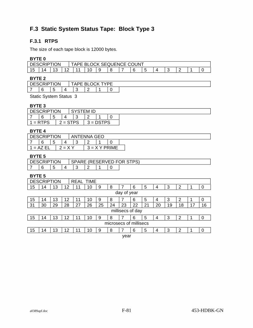
a0389apf.doc F-81 453-HDBK-GN
F.3 Static System Status Tape: Block Type 3
F.3.1 RTPS The size of each tape block is 12000 bytes.
BYTE 0 DESCRIPTION TAPE BLOCK SEQUENCE COUNT 15 14 13 12 11 10 9 8 7 6 5 4 3 2 1 0
BYTE 2 DESCRIPTION TAPE BLOCK TYPE 7 6 5 4 3 2 1 0 Static System Status 3
BYTE 3 DESCRIPTION SYSTEM ID 7 6 5 4 3 2 1 0 1 = RTPS 2 = STPS 3 = DSTPS
BYTE 4 DESCRIPTION ANTENNA GEO 7 6 5 4 3 2 1 0 1 = AZ EL 2 = X Y 3 = X Y PRIME
BYTE 5 DESCRIPTION SPARE (RESERVED FOR STPS) 7 6 5 4 3 2 1 0
BYTE 5 DESCRIPTION REAL TIME 15 14 13 12 11 10 9 8 7 6 5 4 3 2 1 0
day of year
15 14 13 12 11 10 9 8 7 6 5 4 3 2 1 0 31 30 29 28 27 26 25 24 23 22 21 20 19 18 17 16
millisecs of day
15 14 13 12 11 10 9 8 7 6 5 4 3 2 1 0 microsecs of millisecs
15 14 13 12 11 10 9 8 7 6 5 4 3 2 1 0 year

a0389apf.doc F-82 453-HDBK-GN
BYTE 16 DESCRIPTION VALID MESSAGE FLAGS 15 14 13 12 11 10 9 8 7 6 5 4 3 2 1 0 31 30 29 28 27 26 25 24 23 22 21 20 19 18 17 16 Bit set to 1 = message valid in this record. BIT Message Type 17 BROUWER A 18 BROUWER B 19 EPV A 20 EPV B
BYTES 20 - 2669 DESCRIPTION SPARE (RESERVED FOR STPS) 7 6 5 4 3 2 1 0
BYTE 2670 DESCRIPTION BROUWER A 7 6 5 4 3 2 1 0 Up to 850 bytes (see BROUWER description for format)
BYTE 2520 DESCRIPTION BROUWER B 7 6 5 4 3 2 1 0 Up to 850 bytes (see BROUWER description for format)
BYTES 3370 - 4219 DESCRIPTION SPARE (850) (RESERVED FOR STPS) 7 6 5 4 3 2 1 0
BYTE 4220 DESCRIPTION EPV A 7 6 5 4 3 2 1 0 (extended precision vector) Up to 850 bytes (see EPV description for format)
BYTE 5070 DESCRIPTION EPV B 7 6 5 4 3 2 1 0 (extended precision vector) Up to 850 bytes (see EPV description for format)
BYTES 5920 - 6769 DESCRIPTION SPARE (850) (RESERVED FOR STPS) 7 6 5 4 3 2 1 0
BYTES 6770 - 11999 DESCRIPTION SPARE 7 6 5 4 3 2 1 0

a0389apf.doc F-83 453-HDBK-GN
F.3.2 STPS The size of each tape block is 12000 bytes.
BYTE 0 DESCRIPTION TAPE BLOCK SEQUENCE COUNT 15 14 13 12 11 10 9 8 7 6 5 4 3 2 1 0
BYTE 2 DESCRIPTION TAPE BLOCK TYPE 7 6 5 4 3 2 1 0 Static System Status 3
BYTE 3 DESCRIPTION SYSTEM ID 7 6 5 4 3 2 1 0 1 = RTPS 2 = STPS 3 = DSTPS
BYTE 4 DESCRIPTION ANTENNA GEO 7 6 5 4 3 2 1 0 1 = AZ EL 2 = X Y 3 = X Y PRIME
BYTE 5 DESCRIPTION ANTENNA DS MODE 7 6 5 4 3 2 1 0
BYTE 5 DESCRIPTION REAL TIME 15 14 13 12 11 10 9 8 7 6 5 4 3 2 1 0
day of year
15 14 13 12 11 10 9 8 7 6 5 4 3 2 1 0 31 30 29 28 27 26 25 24 23 22 21 20 19 18 17 16
millisecs of day
15 14 13 12 11 10 9 8 7 6 5 4 3 2 1 0 microsecs of millisecs
15 14 13 12 11 10 9 8 7 6 5 4 3 2 1 0 year

a0389apf.doc F-84 453-HDBK-GN
BYTE 16 DESCRIPTION VALID MESSAGE FLAGS 15 14 13 12 11 10 9 8 7 6 5 4 3 2 1 0 31 30 29 28 27 26 25 24 23 22 21 20 19 18 17 16 Bit set to 1 = message valid in this record. BIT Message Type 0 IRV DS 1 LRV DS 2 IIRV DS 4 NORAD DS 5 INP DS 6 BROUWER DS 7 EPV DS 17 BROUWER A 18 BROUWER B 19 EPV A 20 EPV B
BYTE 20 DESCRIPTION IRV DS 7 6 5 4 3 2 1 0 Up to 850 bytes (see IRV description for format)
BYTE 870 DESCRIPTION IIRV DS 7 6 5 4 3 2 1 0 Up to 500 bytes (see IIRV description for format)
BYTE 1370 DESCRIPTION INP DS 7 6 5 4 3 2 1 0 Up to 2500 bytes (see INP description for format)
BYTE 1670 DESCRIPTION NORAD DS 7 6 5 4 3 2 1 0 Up to 500 bytes (see NORAD description for format)
BYTE 2170 DESCRIPTION LRV DS 7 6 5 4 3 2 1 0 Up to 500 bytes IIRV derived from LTAS frame (see IIRV description for format)

a0389apf.doc F-85 453-HDBK-GN
BYTE 2670 DESCRIPTION BROUWER A 7 6 5 4 3 2 1 0 Up to 850 bytes (see BROUWER description for format)
BYTE 2520 DESCRIPTION BROUWER B 7 6 5 4 3 2 1 0 Up to 850 bytes (see BROUWER description for format)
BYTE 3370 DESCRIPTION BROUWER DS 7 6 5 4 3 2 1 0 Up to 850 bytes (see BROUWER description for format)
BYTE 4220 DESCRIPTION EPV A 7 6 5 4 3 2 1 0 (extended precision vector) Up to 850 bytes (see EPV description for format)
BYTE 5070 DESCRIPTION EPV B 7 6 5 4 3 2 1 0 (extended precision vector) Up to 850 bytes (see EPV description for format)
BYTE 5920 DESCRIPTION EPV DS 7 6 5 4 3 2 1 0 (extended precision vector) Up to 850 bytes (see EPV description for format)
BYTES 6770 - 11999 DESCRIPTION SPARE 7 6 5 4 3 2 1 0

a0389apf.doc F-86 453-HDBK-GN
F.4 Static System Status Tape: Block Type 4 (RTPS) The size of each tape block is 12000 bytes.
BYTE 0 DESCRIPTION TAPE BLOCK SEQUENCE COUNT 15 14 13 12 11 10 9 8 7 6 5 4 3 2 1 0
BYTE 2 DESCRIPTION TAPE BLOCK TYPE 7 6 5 4 3 2 1 0 Static System Status 4
BYTE 3 DESCRIPTION SYSTEM ID 7 6 5 4 3 2 1 0 1 = RTPS 2 = STPS 3 = DSTPS
BYTE 4 DESCRIPTION ANTENNA GEO 7 6 5 4 3 2 1 0 1 = AZ EL 2 = X Y 3 = X Y PRIME
BYTE 5 DESCRIPTION SPARE 7 6 5 4 3 2 1 0
BYTE 6 DESCRIPTION REAL TIME 15 14 13 12 11 10 9 8 7 6 5 4 3 2 1 0
day of year
15 14 13 12 11 10 9 8 7 6 5 4 3 2 1 0 31 30 29 28 27 26 25 24 23 22 21 20 19 18 17 16
millisecs of day
15 14 13 12 11 10 9 8 7 6 5 4 3 2 1 0 microsecs of millisecs
15 14 13 12 11 10 9 8 7 6 5 4 3 2 1 0 year

a0389apf.doc F-87 453-HDBK-GN
BYTE 16 DESCRIPTION VALID CALIBRATION FILE 7 6 5 4 3 2 1 0 1 = VALID 0 = INVALID
BYTE 17 DESCRIPTION CALIBRATION FILE 7 6 5 4 3 2 1 0 Up to 1100 bytes of ASCII characters
BYTE 1117 DESCRIPTION VALID SITE FILE 7 6 5 4 3 2 1 0 1 = VALID 0 = INVALID
BYTE 1118 DESCRIPTION SITE FILE 7 6 5 4 3 2 1 0 Up to 4300 bytes of ASCII characters
BYTE 5418 DESCRIPTION VALID MISSION FILE 7 6 5 4 3 2 1 0 1 = VALID 0 = INVALID
BYTE 5419 DESCRIPTION MISSION FILE 7 6 5 4 3 2 1 0 Up to 500 bytes of ASCII characters
BYTES 5919 - 11999 DESCRIPTION SPARE 7 6 5 4 3 2 1 0

a0389apf.doc F-88 453-HDBK-GN
F.5 Static System Status Tape: Block Type 5 (STPS) The size of each tape block is 12000 bytes.
BYTE 0 DESCRIPTION TAPE BLOCK SEQUENCE COUNT 15 14 13 12 11 10 9 8 7 6 5 4 3 2 1 0
BYTE 2 DESCRIPTION TAPE BLOCK TYPE 7 6 5 4 3 2 1 0 Static System Status 5
BYTE 3 DESCRIPTION SYSTEM ID 7 6 5 4 3 2 1 0 1 = RTPS 2 = STPS 3 = DSTPS
BYTE 4 DESCRIPTION ANTENNA GEO 7 6 5 4 3 2 1 0 1 = AZ EL 2 = X Y 3 = X Y PRIME
BYTE 5 DESCRIPTION SPARE 7 6 5 4 3 2 1 0
BYTE 6 DESCRIPTION REAL TIME 15 14 13 12 11 10 9 8 7 6 5 4 3 2 1 0
day of year
15 14 13 12 11 10 9 8 7 6 5 4 3 2 1 0 31 30 29 28 27 26 25 24 23 22 21 20 19 18 17 16
millisecs of day
15 14 13 12 11 10 9 8 7 6 5 4 3 2 1 0 microsecs of millisecs
15 14 13 12 11 10 9 8 7 6 5 4 3 2 1 0 year
BYTE 16 DESCRIPTION VALID RECORD #1 15 14 13 12 11 10 9 8 7 6 5 4 3 2 1 0 1 = VALID 0 = INVALID
BYTE 18 DESCRIPTION NASCOM BLOCK DATA #1 7 6 5 4 3 2 1 0 600 bytes
BYTE 618 DESCRIPTION VALID RECORD #2 15 14 13 12 11 10 9 8 7 6 5 4 3 2 1 0 1 = VALID 0 = INVALID BYTE 620 DESCRIPTION NASCOM BLOCK DATA #2

a0389apf.doc F-89 453-HDBK-GN
7 6 5 4 3 2 1 0 600 bytes
BYTE 1220 DESCRIPTION VALID RECORD #3 15 14 13 12 11 10 9 8 7 6 5 4 3 2 1 0 1 = VALID 0 = INVALID
BYTE 1222 DESCRIPTION NASCOM BLOCK DATA #3 7 6 5 4 3 2 1 0 600 bytes
BYTE 1822 DESCRIPTION VALID RECORD #4 15 14 13 12 11 10 9 8 7 6 5 4 3 2 1 0 1 = VALID 0 = INVALID
BYTE 1824 DESCRIPTION NASCOM BLOCK DATA #4 7 6 5 4 3 2 1 0 600 bytes
BYTE 2424 DESCRIPTION VALID RECORD #5 15 14 13 12 11 10 9 8 7 6 5 4 3 2 1 0 1 = VALID 0 = INVALID
BYTE 2426 DESCRIPTION NASCOM BLOCK DATA #5 7 6 5 4 3 2 1 0 600 bytes
BYTE 3026 DESCRIPTION VALID RECORD #7 15 14 13 12 11 10 9 8 7 6 5 4 3 2 1 0 1 = VALID 0 = INVALID
BYTE 3028 DESCRIPTION NASCOM BLOCK DATA #7 7 6 5 4 3 2 1 0 600 bytes
BYTE 3628 DESCRIPTION VALID RECORD #8 15 14 13 12 11 10 9 8 7 6 5 4 3 2 1 0 1 = VALID 0 = INVALID

a0389apf.doc F-90 453-HDBK-GN
BYTE 3630 DESCRIPTION NASCOM BLOCK DATA #8 7 6 5 4 3 2 1 0 600 bytes
BYTE 4230 DESCRIPTION VALID RECORD #9 15 14 13 12 11 10 9 8 7 6 5 4 3 2 1 0 1 = VALID 0 = INVALID
BYTE 4232 DESCRIPTION NASCOM BLOCK DATA #9 7 6 5 4 3 2 1 0 600 bytes
BYTE 4832 DESCRIPTION VALID RECORD #10 15 14 13 12 11 10 9 8 7 6 5 4 3 2 1 0 1 = VALID 0 = INVALID
BYTE 4834 DESCRIPTION NASCOM BLOCK DATA #10 7 6 5 4 3 2 1 0 600 bytes
BYTE 5434 DESCRIPTION VALID RECORD #11 15 14 13 12 11 10 9 8 7 6 5 4 3 2 1 0 1 = VALID 0 = INVALID
BYTE 5436 DESCRIPTION NASCOM BLOCK DATA #11 7 6 5 4 3 2 1 0 600 bytes
BYTE 6036 DESCRIPTION VALID RECORD #12 15 14 13 12 11 10 9 8 7 6 5 4 3 2 1 0 1 = VALID 0 = INVALID
BYTE 6038 DESCRIPTION NASCOM BLOCK DATA #12 7 6 5 4 3 2 1 0 600 bytes
BYTE 6638 DESCRIPTION VALID RECORD #13 15 14 13 12 11 10 9 8 7 6 5 4 3 2 1 0 1 = VALID 0 = INVALID

a0389apf.doc F-91/(F-92 blank) 453-HDBK-GN
BYTE 6640 DESCRIPTION NASCOM BLOCK DATA #13 7 6 5 4 3 2 1 0 600 bytes
BYTE 7240 DESCRIPTION VALID RECORD #14 15 14 13 12 11 10 9 8 7 6 5 4 3 2 1 0 1 = VALID 0 = INVALID
BYTE 7242 DESCRIPTION NASCOM BLOCK DATA #14 7 6 5 4 3 2 1 0 600 bytes
BYTE 7842 DESCRIPTION VALID RECORD #15 15 14 13 12 11 10 9 8 7 6 5 4 3 2 1 0 1 = VALID 0 = INVALID
BYTE 7844 DESCRIPTION NASCOM BLOCK DATA #15 7 6 5 4 3 2 1 0 600 bytes
BYTE 8444 DESCRIPTION VALID RECORD #16 15 14 13 12 11 10 9 8 7 6 5 4 3 2 1 0 1 = VALID 0 = INVALID
BYTE 8446 DESCRIPTION NASCOM BLOCK DATA #16 7 6 5 4 3 2 1 0 600 bytes BYTES 9046 - 11999 DESCRIPTION SPARE 7 6 5 4 3 2 1 0

a0389abb.doc AB-1 453-HDBK-GN
Abbreviations and Acronyms
ACN Ascension Island
ACC antenna control console
A-D analog-to-digital
ADRAN advanced digital range equipment
ADRS Automatic Digital Recording System
AFETR Air Force Eastern Test Range
AFFTC Air Force Flight Test Center, Edwards Air Force Base
AFSTC Air Force Satellite Test Center
AGO Santiago, Chile, GN station
AGS Alaska Ground Station
ALCOR Advance Research Project Agency, Lincoln, C-band
ANT Antigua Island, USAF ETR station 91
AOS acquisition of signal
APP antenna position programmer
ARC ambiguity resolving code
ASC Ascension Island (U.K.), USAF ETR station 12
ASCII American Standard Code for Information Interchange
ASF Alaska Satellite Facility
ATS Application Technology Satellite
ATSR Application Technology Satellite Range and Range Rate System
az-el azimuth-elevation
BCD binary-coded decimal
BOT beginning of tape
CAI command angle indicator
CCC Central Computer Complex
CD Conversion Device (NISN)
CNES Centre National d'Etudes Spatiales
CPU central processing unit

a0389abb.doc AB-2 453-HDBK-GN
CRC cyclic redundancy code
CRT cathode ray tube
CSTC Consolidated Space Test Center (Sunnyvale, CA)
CT control transformer
D-A digital-to-analog
DCN documentation change notice
DFL double precision floating point
DFM double file mark
DFX double precision fixed point
DIM digital input multiplexer
DIRAM digital range machine
DOD Department of Defense
DOM digital output multiplexer
D-S digital-to-synchro
EAFB Edwards Air Force Base, CA
EOF end of file
EOM end of message
EOT end of transmission; end of tape
EPV extended precision vector
ETR Eastern Test Range, FL
FDF Flight Dynamics Facility
FLT floating point
FOC fraction of circle
FXP fixed point
GBI Grand Bahama Island, USAF ETR station 3
GCE ground control equipment
GDS Goldstone, CA, DSN station
GET ground elapsed time
GMT Greenwich Mean Time
GN Ground Network
GSFC Goddard Space Flight Center, Greenbelt, MD

a0389abb.doc AB-3 453-HDBK-GN
GTK Grand Turk Island, USAF ETR station 7
GTR ground transponder relay
HAW Kokee Park, Kauai, HI
HBK Hartebeesthoek, South Africa
HSDL high-speed data link
HSR high sample rate
Hz Hertz - cycles per second
IACC interface to antenna control console
ICD interface control document
ID identification
IF intermediate frequency
IIRV improved interrange vector
INP internet prediction
I/O input and/or output
IOIS input/output interface subsystem
IP impact prediction
IRV interrange vector
ISS intrasite slaving system
ITDR INP time check override
IUS interim upper stage
JPL Jet Propulsion Laboratory, Pasadena, CA
JSC Johnson Space Center, Houston, TX
kHz kilohertz - thousands of cycles per second
KMR Kwajalein Missile Range, Marshall Island
KPT Kaena Point, HI, ground station
KSC Kennedy Space Center, Cape Canaveral, FL
LAG look angle generation
LCP left-hand circular polarization
LOS loss of signal
LSB least significant bit
LSD least significant digit; low-speed data

a0389abb.doc AB-4 453-HDBK-GN
LSDL low-speed data link
LSR low sample rate
LTAS launch trajectory acquisition system
LTC local transport control
LTDS launch trajectory data system
MA multiple access
MDDF minimum delay data format
MFR multifunction receiver
MGS McMurdo Ground Station
MHz megahertz - millions of cycles per second
MIL Merritt Island, FL, GN station
MLA Merritt Island Launch Area
MRT major range tone
MSB most significant bit
MSD most significant digit
MT minor tone
MTC magnetic tape control
MTU magnetic tape unit
NASA National Aeronautics and Space Administration
Nascom NASA Communications Network
NBE Canberra, Australia, DSN station
NISN NASA Integrated Services Network
NOAA National Oceanic and Atmospheric Administration
NDOSL NASA Directory of Station Locations
NOR NORAD element or bulletin
NORAD North American Air Defense Command
NOSP Network Operations Support Plan
PBI pushbutton indicator
PCA point of closest approach
PDL Ponce de Leon, FL, GN Station
PLL phase-locked loop

a0389abb.doc AB-5 453-HDBK-GN
PMTC Pacific Missile Test Center
PN pseudo-random noise
P/W pulse width
R range
R⋅ range rate
RAP RCA assembly program
RARR range and range rate
RCP right-hand circular polarization
RER receiver/exciter/ranging
RF radio frequency
RID Madrid, Spain, DSN station
RIS Range Instrumentation Ship
RMCP receive monitor control panel
RTLT round trip light time
RTPS Radar Tracking Processor System
RX receiver
SA single access
SBE S-band exciter
SC spacecraft
SCR silicon-controlled rectifier
SCR/DE subcarrier receiver/Doppler extractor
SFM single file mark
SFX single precision fixed point
SGS Svalbard Ground Station
SIC support identification code
SRB solid rocket booster
SRE STDN ranging equipment
SSI software support instruction
SST satellite-to-satellite tracking
STDN Spaceflight Tracking and Data Network

a0389abb.doc AB-6 453-HDBK-GN
STGT Second TDRSS Ground Terminal
SUF site-unique file
SUS Shuttle upper stage
TDP tracking data processor
TDS Tracking Data System (NISN)
TDPS Tracking Data Processor System
TDR tracking data relay
TDRS Tracking and Data Relay Satellite
TDRSS Tracking and Data Relay Satellite System
TLM telemetry
TRACQ tracking and acquisition program
TTCP tracking, telemetry, and command processor
TTY teletype
TX transmitter
ULA Fairbanks, AK, NOAA station
USN Universal Space Network
UTC universal time coordinated
UTDF universal tracking data format
VCO voltage controller oscillator
VCU VHF control unit
VDB Vandenberg Air Force Base, CA, USAF WTR station
VHF very high frequency
VID vehicle indentification code
WFF Wallops Flight Facility
WLP Wallops Island, NASA tracking radar
WGS Wallops Ground Station
WSGT White Sands Ground Terminal
WSGTU White Sands Ground Terminal Upgrade
WSSH White Sands Space Harbour
WTR Western Test Range
ZSB zero-set bias