Embed Size (px)
Citation preview

Design Guide
© 2010 Cisco and/or its affiliates. All rights reserved. This document is Cisco Public Information. Page 1 of 21
Cisco Data Center Services Node Architecture
The Cisco® Data Center Service Node (DSN) is a new product offering from Cisco that complements the
Cisco Nexus® 7000 Series Switches in the data center. Cisco DSN is the platform of choice to host
specific integrated network services relevant in a given data center. Examples of network services include
the Cisco Firewall Services Module (FWSM) and the Cisco ACE Application Control Engine Module, for
server load balancing. The service node-based solution offers proven enterprise products enabling
customers to use a common architecture and easily integrate the solution with existing network
infrastructure. Deploying a consistent architecture using a common platform can reduce connectivity costs
significantly and increase network performance, manageability, and flexibility.
Cisco DSN uses a dual-homed approach for data path connectivity to redundant aggregation-layer switches. This
approach decouples the service modules from dependence on a specific aggregation switch.
Because the Cisco DSN is self-contained, it provides operational flexibility for the system maintenance that may be
required for the aggregation-layer switches or the Cisco DSN. From a high-availability perspective, if one of the
aggregation switches or Cisco DSNs fails, traffic can continue to flow through the other aggregation switch to the
active Cisco DSN without the need of any failover event in the service modules themselves.
Introduction
This document provides reference design and configuration guidance about integrating the Cisco DSN into an
enterprise data center. The Cisco DSN is a dedicated Cisco Catalyst® 6500 Series services chassis housing three
Cisco FWSMs and one Cisco ACE Module, providing up to 15 Gbps of secure load-balancing system throughput.
The Cisco DSN enables cloud services by integrating firewall security and application delivery along with third-party
solutions and monitoring.
Audience
This document is intended for network engineers and architects who need to understand the design options and
required configurations for the Cisco DSN (services chassis) architecture in a data center network.
Data Center
The data center is evolving into a cloud services environment. A cloud service is defined as providing infrastructure,
platform, and software as a service. By moving toward a cloud computing environment, data centers can reduce
costs, provide dynamic resources, improve flexibility, increase service-level agreements (SLAs), and increase space,
bandwidth, and throughput. These benefits are especially important for the rapidly evolving area of data center
networking. The need for higher-performing end nodes and along with the need for solutions that achieve more at
less cost together are propelling data centers to migrate to 10 Gigabit Ethernet and implement server, network, and
services virtualization.
As the network expands, a dedicated Cisco DSN is required to isolate all the services functions onto their own layer.
A major advantage of the Cisco DSN is the capability to introduce new services in a controlled manner using
predictable traffic patterns. The Cisco DSN consists of a Cisco Catalyst 6500 Series Switch using service modules
that are dedicated to security and server load-balancing functions. The Cisco DSN can be directly attached to an
aggregation-layer switch, such as a Cisco Nexus 7000 Series Switch, or it can use the Cisco DSN as the
aggregation layer if ports are available. The primary goal of the Cisco DSN is to provide higher performance,
Design Guide
© 2010 Cisco and/or its affiliates. All rights reserved. This document is Cisco Public Information. Page 2 of 21
reliability, and manageability by transparently applying network services in the data center to create a more flexible,
functional, and secure server farm.
In the first phase of Cisco DSN, two design scenarios are being evaluated. Design 1 (see Figure 1 later in this
document) focuses on a Layer 3 Cisco DSN with a routed Cisco FWSM and Cisco ACE along with virtual route
forwarding (VRF) instances defined on the Cisco Catalyst 6500 Series Multilayer Switch Feature Card (MSFC) of the
Cisco DSN. In design 2 (shown in Figure 3 later in this document), the Cisco DSN is on Layer 2, where no routing
takes places and both the Cisco ACE and Cisco FWSM are in transparent mode. The Cisco DSN applies the
concept of virtualization to the services-layer chassis. In each of the design cases, traffic that is segmented from the
core or aggregation layer is extended to the Cisco DSN. The VRF instance is mapped to an individual Cisco FWSM
or Cisco ACE context, which is then mapped to the individual VLANs. By doing this in a cloud service data center
deployment, customers can each have their own dedicated routing instances, a unique Cisco FWSM and Cisco ACE
context, and a VLAN that extends to a particular service. Through virtualization, resources can be partitioned, giving
each context its own access control lists (ACLs), policies, interfaces, routing, etc, allowing customization and
isolation for each customer. This flexibility enables the network administrator to achieve the best use of resources
available from the Cisco DSN. The Cisco DSN allows traffic to be segmented throughout all layers of the network,
providing an end-to-end cloud services model.
The data center is an important part of the enterprise network. The data center network design must address high
availability for any device or link failure. Additional intelligence is required to provide services such as firewalling and
load balancing of servers and the applications they host. This document examines architectural models for
integrating the Cisco DSN into the data center design.
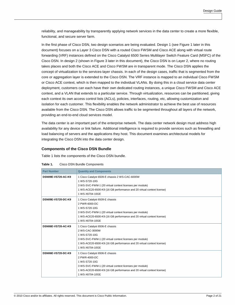
Components of the Cisco DSN Bundle
Table 1 lists the components of the Cisco DSN bundle.
Table 1. Cisco DSN Bundle Components
Part Number Quantity and Components
DSN09E-VS720-AC-K9 1 Cisco Catalyst 6509-E chassis 2 WS-CAC-6000W
1 WS-S720-10G
3 WS-SVC-FWM-1 (20 virtual context licenses per module)
1 WS-ACE20-6500-K9 (16 GB performance and 20 virtual context license)
1 WS-X6704-10GE
DSN09E-VS720-DC-K9 1 Cisco Catalyst 6509-E chassis
2 PWR-6000-DC
1 WS-S720-10G
3 WS-SVC-FWM-1 (20 virtual context licenses per module)
1 WS-ACE20-6500-K9 (16 GB performance and 20 virtual context license)
1 WS-X6704-10GE
DSN06E-VS720-AC-K9 1 Cisco Catalyst 6506-E chassis
2 WS-CAC-3000W
1 WS-S720-10G
3 WS-SVC-FWM-1 (20 virtual context licenses per module)
1 WS-ACE20-6500-K9 (16 GB performance and 20 virtual context license)
1 WS-X6704-10GE
DSN06E-VS720-DC-K9 1 Cisco Catalyst 6506-E chassis
2 PWR-4000-DC
1 WS-S720-10G
3 WS-SVC-FWM-1 (20 virtual context licenses per module)
1 WS-ACE20-6500-K9 (16 GB performance and 20 virtual context license)
1 WS-X6704-10GE

Design Guide
© 2010 Cisco and/or its affiliates. All rights reserved. This document is Cisco Public Information. Page 3 of 21
Part Number Quantity and Components
DSN9VE-VS720-AC-K9 1 Cisco Catalyst 6509-V-E chassis
2 WS-CAC-6000W
1 WS-S720-10G
3 WS-SVC-FWM-1 (20 virtual context licenses per module)
1 WS-ACE20-6500-K9 (16 GB performance and 20 virtual context license)
1 WS-X6704-10GE
DSN9VE-VS720-DC-K9 1 Cisco Catalyst 6509-E chassis
2 PWR-6000DC
1 WS-S720-10G
3 WS-SVC-FWM-1 (virtual context virtual context license)
1 WS-ACE20-6500-K9 (16 GB performance and 20 virtual context license)
1 WS-X6704-10GE
Note: The Cisco FWSM and Cisco ACE are not limited to the support of the chassis, power supplies, and line
cards listed here. The list of hardware is specific to the Cisco DSN bundle that can be ordered.
Virtualization
You can use varying degrees of virtualization in the network to help increase resources, bandwidth, and
performance, and you can use various technologies and features to help accelerate virtualization in the data center.
The Cisco DSN design cases use virtual device contexts (VDC), virtual PortChannel (vPC), virtual switching system
(VSS), VRF, and Cisco FWSM and Cisco ACE virtualization.
VDC allows engineers to logically partition or virtualize the Cisco Nexus 7000 Series connections to multiple logical
devices. A VDC contains its own unique and independent set of VLANs and VRF instances. Each VDC can have a
separate port assigned, allowing the hardware date plane to be virtualized as well. Within each VDC, a separate
management domain can manage each VDC, allowing the management plane to be virtualized as well. VDCs are
used to improve ease of configuration, supportability, and security. vPC is a feature on the Cisco Nexus 7000 Series
that allows an EtherChannel to be formed across two physical devices.
VSS combines two physical Cisco Catalyst 6500 Series Switches into one virtualized switch. This arrangement
enables a unified control plane and also allows both data planes to forward simultaneously. With VSS, multichassis
EtherChannel (MEC) is introduced, which allows a PortChannel to be formed across two physical switches. vPC and
VSS both provide enhanced system availability through redundant systems, eliminate reliance on Spanning Tree
Protocol, achieve faster convergence times, and enable full system availability at all time. For the Cisco DSN use
cases, the aggregation-layer switches can run in vPC mode and interconnect to the Cisco DSN through MEC, which
will be running in the VSS. An additional benefit of integrating VSS with Cisco DSN is that this integration increases
the number of supported service modules per chassis from four to eight in a single VSS domain, enabling an active-
active highly available service chassis.
VRF instances allow multiple routing configurations in a single Layer 3 switch, with separate virtual routing tables.
VRF-lite segregates customer traffic at Layer 3 to optimize use of data center resources. VRF-lite end-to-end
techniques are used to provide customer path isolation. VRF offers these advantages:
● True routing and forwarding segmentation
● Simplified path differentiation (different default routes can be used for each VRF instance)
● Support on both Cisco Catalyst 6500 Series and Cisco Nexus 7000 Series platforms
Each customer is assigned a VRF identity. VRF information is carried across all the hops in a Layer 3 domain, and
these VRF’s will then be mapped to one or more VLANs in a Layer 2 domain. Communication between VRF
instances is not allowed by default to protect the privacy of each customer.

Design Guide
© 2010 Cisco and/or its affiliates. All rights reserved. This document is Cisco Public Information. Page 4 of 21
Virtualization on Cisco FWSM
A single Cisco FWSM can be divided into multiple virtual devices, with each virtual device known as a security
context. Each context has its own security policy, interfaces, and administrators. Having multiple contexts is similar
to having multiple standalone devices and is a great way to reduce costs while keeping all customer traffic separate
and secure. Many features are supported in multiple-context mode, including routing tables, firewall features, and
management. The Cisco FWSM supports up to 250 virtual contexts.
The Cisco FWSM provides the following features:
● Route health injection (RHI)
● Virtualization (context and resource allocation)
● Application inspection
● Redundancy (active-active context failover)
● Security and inspection
● Network Address Translation (NAT) and Port Address Translation (PAT)
● URL filtering
● Layer 2 and 3 firewalling
● Protocol inspection
Virtualization on Cisco ACE
The virtualized environment is divided into objects called contexts. Each context behaves like an independent Cisco
ACE with its own policies, interfaces, domain, server farms, real servers, and administration. You can use it to
provision resources per context with most feature subsystems virtualized.
The Cisco ACE Module provides the following features:
● RHI
● Virtualization (context and resource allocation)
● Probes and server farm (service health checks and load-balancing predictor)
● Stickiness (source IP and cookie insert)
● Load balancing (protocols, stickiness, FTP inspection, and SSL termination)
● NAT (static and dynamic NAT for management and software updates)
● Redundancy (active-active context failover)
The Cisco FWSM and Cisco ACE both have distinct feature sets in security and application load balancing.
However, several security features overlap between the two, as shown in Table 2.
Table 2. Security Features: Comparison of Cisco FWSM and Cisco ACE
Feature Cisco FWSM Cisco ACE
Bidirectional NAT, static and dynamic NAT and PAT, and policy-based NAT Yes Yes
VRF-aware NAT Yes No
Destination NAT for multicast Yes No
Static routing (Layer 2 only) Yes Yes

Design Guide
© 2010 Cisco and/or its affiliates. All rights reserved. This document is Cisco Public Information. Page 5 of 21
Feature Cisco FWSM Cisco ACE
Dynamic routing (Open Shortest Path First [OSPF], Routing Information Protocol [RIP] Versions 1 and 2, Protocol-Independent Multicast [PIM], Internet Group Management Protocol [IGMP] Version 2, and Internet Border Gateway Protocol [iBGP] in single and multiple context)
Yes No
URL filtering (HTTP, HTTPS, and FTP) Yes Yes
DOS Yes Yes
Domain Name System (DNS) guard Yes No
Flood guard and defender Yes No
TCP intercept with SYN cookie Yes Yes
Unicast Reverse Path Forwarding (URPF) Yes Yes
Mail guard Yes No
Virtual reassembly Yes Yes
ICMP stateful inspection Yes Yes
UDP rate control Yes Yes
TCP stream reassembly Yes Yes
TCP traffic normalization services for attack detection Yes Yes
NAT translation bypass Yes No
Selective TCP state bypass per flow Yes No
Bidirectional ACL, extended ACL for IP traffic, and EtherType ACL for non-IP traffic Yes Yes
Per-user ACL and override and time-based ACL Yes No
Address Resolution Protocol (ARP) inspection in Layer 2 mode Yes Yes
Dynamic Host Configuration Protocol (DHCP) server and relay Yes No
Simple Network Management Protocol (SNMP) and syslog Yes Yes
Protocol inspection Yes Yes
Active-Active Mode with Multiple Virtual Contexts
With VSS, the service modules will be in active-active mode, with each virtual context in active-standby mode on the
designated service modules of each Cisco DSN.
This model uses the virtualization capabilities of the Cisco FWSM and Cisco ACE Module to distribute a portion of
the traffic across both services chassis. The traffic is not automatically balanced equally across the devices;
however, the network administrator can assign different server farm subnets to specific contexts, based on expected
load or on other factors. Routing virtualization is also used in the active-active model through the implementation of
VRF instances in the aggregation switches. In the active-active routed Cisco DSN model (see Figure 1 later in this
document), all Layer 3 processing takes place on the Cisco DSN, making both the Cisco FWSM and Cisco ACE in
routed mode. In Design 2, the transparent Cisco DSN model acts as a pure Layer 2-connected switch.
The active-active design model allows the Cisco FWSM and Cisco ACE in the Cisco DSN to support an active
context, optimizing resources in each Cisco DSN through load distribution across the Cisco DSN pair (VSS). To
achieve an active-active design, failover groups are defined for each service module. Failover groups contain virtual
contexts and determine which physical Cisco FWSM and Cisco ACE will be active for the particular group. Each
module is assigned a primary and secondary priority status for the failover group. The fault-tolerant interface
between the Cisco FWSM and Cisco ACE on each chassis uses a separate physical connection between chassis.
Since the Cisco DSN is a VSS configuration, all configured VLANs are carried across the virtual switch links (VSLs).
As a result, no separate links are needed for fault-tolerant links or stateful connectivity.
With the virtualization capabilities of the Cisco Catalyst 6500 Series services modules, separate contexts can be
created that behave like separate virtual devices. The first Cisco FWSM and Cisco ACE are primary for the first
context and standby for the second context. The second Cisco FWSM and Cisco ACE are primary for the second

Design Guide
© 2010 Cisco and/or its affiliates. All rights reserved. This document is Cisco Public Information. Page 6 of 21
context and secondary for the first context. This setup allows modules on both sides of the designs to be primary for
a portion of the traffic, and it allows the network administrator to optimize network resources by distributing the load
across the topology instead of having one set of modules nearly idle in a pure-standby role.
Note: In an active-active design, network administrators must properly plan for failure events in which one service
module supports all the active contexts. If the total traffic exceeds the capacity of the remaining service module, the
potential to lose connections exists; thus, it is important to size the VSL accordingly. It is a best practice for the
bandwidth of the VSL to be equal to the total amount of uplink traffic coming into a single chassis.
For more information, please refer to these links:
● http://www.cisco.com/en/US/products/ps9336/products_tech_note09186a0080a7c72b.shtml
● http://www.cisco.com/go/vss/
Design Considerations
For Cisco DSN, two design options are considered here. In option 1, routed Cisco DSN (shown in Figure 1 later in
this document), the Cisco FWSM and Cisco ACE both are in routed mode. In addition, VRF is defined on the Cisco
DSN MSFC. The routed Cisco DSN use case has been validated by Enterprise Solutions Engineering. For more
detailed information about this use case, please refer to
http://nsite.cisco.com/publications/viewdoc.php?docid=5656.
In option 2 (see Figure 3 later in this document), called transparent Cisco DSN, no routing occurs on the Cisco DSN,
and the Cisco FWSM and Cisco ACE are set to transparent mode. The option 2 design guide and validation are
expected to be available the third quarter of 2010 (Q3CY2010).
For both design options, there are two use cases: one with Cisco FWSM facing the servers, and one with Cisco ACE
facing the servers. Depending on the design requirements, Cisco FWSM or Cisco ACE can face the servers. In the
routed Cisco DSN validated design, Cisco FWSM faces the servers.
Having Cisco FWSM face the inside server farm and Cisco ACE face the Internet offers several benefits:
● In a large managed data center deployment, the service provider can provide an initial firewall outside the
data center network.
● The firewall inside the data center network protects inter-data center traffic (that is, traffic from critical servers
to noncritical servers and the opposite).
● The Cisco FWSM is positioned as the default gateway for the servers in the server farm. If Cisco FWSM is
used as the default gateway for a server subnet, any server-to-server traffic between subnets is firewalled as
well. For example, n-tier applications using application-to-database server connectivity can be secured.
● At the data center entry point, Cisco ACE can handle the Layer 4 to 7 security (inspection) along with basic
NAT and PAT.
● The ACL provides load balancing across the various application servers.
● Cisco ACE can serve as a load balancer across multiple firewalls to provide higher firewall throughput.
Having Cisco ACE facing the inside server farm and Cisco FWSM facing the Internet offers these benefits:
● This approach can be applicable in a private data center owned and operated by a large enterprise.
● Cisco ACE server load balancing serves as a pure load balancer across application servers.
● Cisco FWSM provides a first layer of defense across Layer 2 to 7, NAT and PAT, and application inspection.
● Cisco FWSM can segregate traffic at the data center edge into inside, outside, and DMZ traffic with different
policies.

Design Guide
© 2010 Cisco and/or its affiliates. All rights reserved. This document is Cisco Public Information. Page 7 of 21
Design Option 1: Routed Cisco DSN
Design option 1 (Figure 1) uses routed Cisco DSN. With routed Cisco DSN, both the Cisco FWSM and Cisco ACE
are in routed mode, thus forming one of the two default gateway for the servers. A routed service device is
conceptually easier to implement and troubleshoot than a transparent service device, since there is a one-to-one
correlation between VLANs and subnets and a simplified spanning-tree structure because the device is not
forwarding Bridge Protocol data units (BPDUs) between VLANs.
Figure 1. Routed Cisco DSN: Physical Topology
The Cisco ACE can be configured with SSL offload for virtual machines. It uses multiple VLANs to segment virtual
machines into different networks hosting multi-tiered applications. The Cisco ACE is configured to run with multiple
contexts in routed mode. For server load-balancing (SLB) traffic, each context is configured with client- and server-
facing VLANs. The server-facing VLAN is shared with the outside VLAN on the Cisco FWSM. The Cisco ACE uses
static routes with the Cisco FWSM as the gateway to reach the virtual machines.
The Cisco FWSM is configured to run in multiple-context routed mode, acting as the default gateway for the virtual
machines. In routed mode, the Cisco FWSM acts as a router between connected networks, and each interface
requires an IP address on a different subnet. The firewall context provides security between virtual machine VLANs,
which are associated with a single customer, and routes traffic between the VLANs and outbound network as
required. Each firewall is configured with VLANs local to the virtual machines and uses a static default route to route
traffic to clients, pointing to the Cisco ACE’s server-side VLAN’s alias IP address. Multiple-context mode supports

Design Guide
© 2010 Cisco and/or its affiliates. All rights reserved. This document is Cisco Public Information. Page 8 of 21
static routes only, so the Cisco FWSM is configured to use a static default route to the Cisco ACE for client or
outbound access. The Cisco FWSM does not support dynamic routing in multiple-context mode.
Figure 2 shows the logical topology.
Figure 2. Routed Cisco DSN: Logical Topology
Traffic flows from the client to the server and from the server to the client as follows:
1. Traffic from clients to the virtual IP is routed to the edge router.
2. The edge router routes traffic to the appropriate VRF instance (VRF Red) on the Cisco DSN.
3. The Cisco DSN routes this traffic to the outside Cisco ACE context’s client-facing VLAN 200.
4. The Cisco ACE context performs server load balancing.
5. The Cisco ACE context rewrites the destination address to the address of the virtual machine.
6. The Cisco ACE uses static routes to forward the traffic from the server-side VLAN to the shared (outside) Cisco
FWSM, VLAN 100.
7. The Cisco FWSM forwards traffic directly to the servers, using a separate VLAN for each application type.
8. Return traffic from the virtual machines is routed back to the Cisco FWSM (default gateway), VLAN 20.
9. The Cisco FWSM uses the default route and forwards traffic to the Cisco ACE’s server-facing VLAN through the
shared (outside) Cisco FWSM, VLAN 100.
10. The Cisco ACE context has a default route for the client traffic pointing to a Layer 3 switch virtual interface (SVI)
(VRF Red) on the services switch, accessible through the client, VLAN 200.

Design Guide
© 2010 Cisco and/or its affiliates. All rights reserved. This document is Cisco Public Information. Page 9 of 21
11. The Cisco ACE contexts rewrites the source address as the virtual IP address and routes traffic to the Cisco
DSN (MSFC).
12. Using dynamic routing, the VRF on the Cisco DSN (MSFC) forwards the traffic to the edge router through Layer
2 to the aggregation switch.
13. The edge router routes traffic to the Internet backbone or VPN.
Note: The routed Cisco DSN design use case has been validated by the services and systems business team).
For more information, see http://nsite.cisco.com/publications/viewdoc.php?docid=5656.
Design Option 2: Transparent Cisco DSN
In transparent mode (Figure 3), the service modules bridge traffic from the VLANs that are chained together. The
traffic is forwarded across a distinct set of VLANs within a subnet, acting as a “bump in the wire.”
Figure 3. Transparent Cisco DSN: Physical Topology
A transparent firewall requires less configuration than a routed firewall, since there is no routing protocol to configure
or list of static routes to maintain. It requires only a single IP subnet on the bridge-group interface, and it forwards
BPDUs between bridging devices that reside on attached segments; in that way, it is truly transparent and not a
bridge itself. The VLANs on the different interfaces of the transparent Cisco FWSM have different VLAN numbers, so
a transparent device is often said to chain VLANs together.

Design Guide
© 2010 Cisco and/or its affiliates. All rights reserved. This document is Cisco Public Information. Page 10 of 21
Note: The Cisco FWSM supports a maximum of eight bridge-group virtual interfaces (BVIs) per context.
In the transparent Cisco DSN model, the Cisco FWSM is configured for multiple-context transparent mode in an
active-active Cisco DSN. Having the Cisco FWSM in transparent mode helps ensure that the firewall context is in the
path of traffic and is capable of applying the security polices defined for it.
Cisco ACE is used as multiple-context in bridged mode. The transparent Cisco ACE implementation works similarly
to the Cisco FWSM implementation, in which multiple VLANs are chained together to transport one IP subnet, and
BPDUs are forwarded to allow adjacent switches to perform spanning-tree calculations. A transparent Cisco ACE
sits in line with traffic and requires no traffic-diversion mechanism to help ensure that both sides of a protocol
exchange pass through the device. The Cisco ACE supports a maximum of two Layer 2 interface VLANs per bridge
group and a maximum of 2000 BVIs per system. The BVI is configured to provide VLAN bridging.
The VDC capability of the Cisco Nexus 7000 Series enables the network architect to use VDC. A secondary virtual
switching layer called the subaggregation layer can be created using VDCs, located between the Cisco DSN and the
access switches. The insertion of a separate set of VDCs into the design still represents the use of a single physical
pair of switches to perform these functions but provides better isolation between the routing environments above and
below the Cisco DSN. The Cisco DSN must have separate physical connections to both sets of VDCs rather than
having VLANs sharing the same trunks. Additional interfaces must also be provisioned to support the Inter-Switch
Link (ISL) between the two subaggregation-layer VDCs.
Figure 4 shows the logical topology.
Figure 4. Transparent Cisco DSN: Logical Topology

Design Guide
© 2010 Cisco and/or its affiliates. All rights reserved. This document is Cisco Public Information. Page 11 of 21
Traffic flows as follows:
1. The customer is identified by VRF Red, defined on the edge router.
2. VRF Red traffic from clients to the server virtual IP address is routed to the aggregation switch.
3. VRF Red traffic is associated with VLAN 300 and is transported across an IEEE 802.1q trunk through Layer 2
(VLAN 300) to the Cisco DSN active Cisco FWSM context.
4. The Cisco FWSM context performs a security check and bridges the traffic from the server-side VLAN to the
shared (outside) Cisco ACE, VLAN 200.
5. The Cisco ACE context performs server load balancing.
6. The Cisco ACE context bridges the traffic to VLAN 100 and rewrites the destination address as the address of
the virtual server. Traffic is forwarded across the Layer 2 trunk to the subaggregation-layer switch.
7. The subaggregation-layer switch forwards traffic from VLAN 100 from the inside Cisco ACE VLAN to the server
(VLAN 21) and associates it with VRF Red.
8. The subaggregation-layer switch routes the traffic to the appropriate server.
9. Return traffic from the virtual machines is routed back to the subaggregation-layer switch through VRF Red
(VLAN 21), which is the default gateway.
10. The subaggregation-layer switch forwards the traffic to the inside Cisco ACE, VLAN 100.
11. The Cisco ACE context rewrites the source address as the virtual IP address and bridges the traffic to the Cisco
FWSM.
12. The Cisco ACE forwards the traffic to the server-facing VLAN through the shared (outside) Cisco FWSM,
VLAN 200.
13. The Cisco FWSM context has a default route for the client traffic pointing to the Cisco DSN MSFC through
VLAN 300.
14. The Cisco DSN forwards the traffic through Layer 2 (VLAN 300) to the aggregation switch, which routes the
traffic to the Internet backbone or VPN through VRF Red.
Note: The transparent Cisco DSN model is currently in the validation process by the services and systems
business team. The design guide is expected in Q3CY2010.
In both the routed and transparent options, the Cisco DSN is in an active-active configuration. In an active-active
configuration, a particular context can be in active mode on one service module and in standby mode on the other;
per context basis Cisco ACE and Cisco FWSM provides traffic load-balancing. As shown in the topology, the Red
context is active on the left Cisco ACE, and the Green context is active on the right Cisco ACE. Both contexts are in
standby mode on the respective peer Cisco ACE modules, and additional VLANs are carried over the ISL to provide
fault tolerance and state synchronization. If one of the Cisco ACEs incurs a failure, the standby context on the peer
Cisco ACE will become active right away with little traffic distruption. Active-active design enables traffic load sharing
and redundancy. As shown in Figure 4, client-to-server traffic for some contexts will use the links on the left, and the
rest will use the links on the right.
In both Figures 3 and 4, the fault-tolerant link for the Cisco FWSM context between the Cisco DSN nodes consists of
VLANs 171 and 172. The Cisco ACE context has a dedicated fault-tolerant interface, VLAN 160. This VLAN provides
configuration synchronization, state replication, and unit monitoring functions. Fault-tolerant groups enable greater
availability and load distribution in the data center by allowing the distribution of active virtual contexts between two
peering Cisco ACE Modules. In an active-active design, at least two fault-tolerant groups must be defined. To
distribute the workload between the Cisco ACE Modules, set the primary and secondary priorities to each fault-
tolerant group and alternating peers.

Design Guide
© 2010 Cisco and/or its affiliates. All rights reserved. This document is Cisco Public Information. Page 12 of 21
Management of Cisco DSN
Two options are available to manage the Cisco DSN. The first management option uses traditional device
management tools that are already available to support the Cisco Catalyst 6500 Series, Cisco FWSM, and Cisco
ACE. These tools include the CiscoWorks LAN Management Solution (LMS), Cisco Security Manager, Cisco
Application Network Manager (ANM), respectively. All three pieces of management software can be loaded onto a
single VMware ESX server and be managed from one management device.
With the introduction of Cisco DSN, there is a new tool that can help provision, manage, and configure the Cisco
DSN: BMC BladeLogic Network Automation (BBNA). This tool has been completely customized for use with the
Cisco DSN and helps automate the initial setup and management of Cisco DSN, configure the Cisco DSN as either
a routed or transparent Cisco DSN, and provision the Cisco DSN based on specific server applications. The BBNA
tool configures the entire Cisco DSN from end to end.
Cisco DSN Management Configuration
When a Cisco DSN is deployed, the BBNA tool automates the configuration to provide initial manageability in the
Cisco ACE and Cisco FWSM. The initial requirement is for the end customer to set up a management VLAN and IP
address on the Cisco Catalyst 6500 Series Switch. After the autoscript is complete, the Cisco Catalyst 6500 Series
Switch configuration will be added to the switch, Cisco FWSM, and Cisco ACE, allowing for the customer to access
and manage the Cisco DSN.
Cisco Catalyst 6500 Series Switch Configuration
vrf mgmt
vlan 2
management vlan
Interface Vlan 2
Description Management Vlan
ip address 10.1.1.10 255.255.255.0
ip vrf forwarding mgmt
ip route vrf mgmt 0.0.0.0 0.0.0.0 10.1.1.1
The ACE uses svclc and for the FWSM use the firewall command. In this topology, some of the VLANs are common (shared) between the ACE and FWSM. To configure, designate a particular VLAN-group to carry these VLANS. Then share this group “vlan-group x” across the two commands:
svclc multiple-vlan-interfaces
svclc switch 1 module 6 vlan-group 2
svclc vlan-group 2 2
fwsm multiple-vlan-interfaces
firewall switch 1 module 1 vlan-group 2
firewall vlan-group
Cisco FWSM
admin-context admin
context admin
allocate-interface Vlan2

Design Guide
© 2010 Cisco and/or its affiliates. All rights reserved. This document is Cisco Public Information. Page 13 of 21
config-url disk:/admin.cfg
interface Vlan2
nameif mgmt
security-level 100
ip address 10.1.1.2 255.255.255.0
route mgmt 0.0.0.0 0.0.0.0 10.1.1.1 1
Cisco ACE
class-map type management match-any mgmt_traffic
2 match protocol ssh any
3 match protocol telnet any
4 match protocol snmp any
5 match protocol icmp any
6 match protocol http any
7 match protocol https any
policy-map type management first-match mgmt_policy
class mgmt_traffic
permit
interface Vlan2
ip address 10.1.1.3 255.255.255.0
service-policy input mgmt_policy
no shutdown
ip route 0.0.0.0 0.0.0.0 10.1.1.1
Cisco DSN Provisioning
Cisco DSN provisioning is based on the two design options discussed in this document: routed and transparent
Cisco DSN. When the Cisco ACE Module and Cisco FWSM are installed in a VSS chassis, you must manually
assign VLANs to the modules: called VLAN chaining. This process is performed on a per-context and per-VLAN
basis to isolate each customer.
Routed Cisco DSN
Cisco Catalyst 6500 Series Switch Configuration
vrf red
vlan 20
vlan 100
vlan 200
interface Vlan 200
description vlan facing ace
ip address 200.1.1.1 255.255.255.0
ip vrf forwarding

Design Guide
© 2010 Cisco and/or its affiliates. All rights reserved. This document is Cisco Public Information. Page 14 of 21
interface tengigabit ethernet 3/1
description trunk to aggregation switch
switchport
switchport mode trunk
svclc module 2 vlan-group 2,100
svclc vlan-group 100 20,100,200
firewall multiple-vlan-interfaces
firewall module 3 vlan-group 2,100
Cisco FWSM
Adds Layer 3 FWSM context
context routedtest
allocate-interface Vlan20
allocate-interface Vlan100
config-url disk:/routedtest.cfg
Builds Layer 3 FWSM Context
changeto context routedtest
firewall routed
interface Vlan 100
nameif outside
ip address 100.1.1.1. 255.255.255.0
security-level 0
!
interface Vlan 20
nameif inside
ip address 20.1.1.1 255.255.255.0
ip route 0.0.0.0 0.0.0.0 100.1.1.2
!
access-list ANY extended permit ospf any any
access-list ANY extended permit ip any any
access-list ANY extended permit icmp any any
icmp permit any inside
icmp permit any enterprise
access-group ANY in interface inside
access-group ANY in interface enterprise
Cisco ACE
Add Layer 3 ACE Context
context routedtest

Design Guide
© 2010 Cisco and/or its affiliates. All rights reserved. This document is Cisco Public Information. Page 15 of 21
allocate-interface vlan 100
allocate-interface vlan 200
Build Layer 3 ACE context
access-list BPDUALLOW ethertype permit bpdu
access-list ANY extended permit ip any any
!
interface vlan 100
ip address 100.1.1.2 255.255.255.0
access-group input BPDUALLOW
access-group input ANY
no shutdown
interface vlan 200
ip address 200.1.1.2 255.255.255.0
access-group input BPDUALLOW
access-group input ANY
no shutdown
!
ip route 0.0.0.0 0.0.0.0 200.1.1.1
Transparent Cisco DSN
Cisco Catalyst 6500 Series Switch Configuration
svclc module 2 vlan-group 2,100
svclc vlan-group 100 2, 100, 200
firewall multiple-vlan-interfaces
firewall module 3 vlan-group 2,100
Cisco FWSM
Adds Layer 2 FWSM context
context transparenttest
allocate-interface Vlan200
allocate-interface Vlan300
config-url disk:/transparenttest.cfg
Builds Layer 2 FWSM Context
changeto context transparenttest
firewall transparent
interface Vlan 300
nameif outside
bridge-group 1
security-level 0

Design Guide
© 2010 Cisco and/or its affiliates. All rights reserved. This document is Cisco Public Information. Page 16 of 21
!
interface Vlan 200
nameif inside
bridge-group 1
!
interface BVI1
ip address 110.1.1.200 255.255.255.0
!
access-list ANY extended permit ospf any any
access-list ANY extended permit ip any any
access-list ANY extended permit icmp any any
icmp permit any inside
icmp permit any enterprise
access-group ANY in interface inside
access-group ANY in interface enterprise
Cisco ACE
Add Layer 2 ACE Context
Resource-class sticky
Limit-resource all minimum 0.00 maximum unlimited
limit-resource sticky min 20.00 max unlimited
context transparenttest
allocate-interface vlan 200
allocate-interface vlan 100
member sticky
Build Layer2 ACE context
access-list BPDUALLOW ethertype permit bpdu
access-list ANY extended permit ip any any
!
interface vlan 200
bridge-group 1
access-group input BPDUALLOW
access-group input ANY
no shutdown
interface vlan 100
bridge-group 1
access-group input BPDUALLOW
access-group input ANY
no shutdown
!
interface bvi 1
ip address 110.1.1.100 255.255.255.0

Design Guide
© 2010 Cisco and/or its affiliates. All rights reserved. This document is Cisco Public Information. Page 17 of 21
no shutdown
Cisco DSN Application Provisioning
Certain applications require specific configurations on the Cisco FWSM and Cisco ACE. The three most common
applications are web server, Microsoft Exchange, and SQL server.
Web Server Configuration
Cisco FWSM
! Allow all traffic out
access-list inside_access_in permit ip any any
access-group inside_access_in in interface inside
! Allow traffic from outside to inside server
access-list outside_access_in permit tcp any host 20.1.1.70 eq www
access-list outside_access_in permit tcp any host 20.1.1.70 eq https
access-list outside_access_in permit icmp any any
access-group outside_access_in in interface outside
! Static NAT for inside server, makes it accessible from outside
static (inside,outside) 20.1.1.70 20.1.1.70 netmask 255.255.255.255
! Functional inspection to make some protocols work through firewall/nat
class-map inspection_default
match default-inspection-traffic
policy-map global_policy
class inspection_default
inspect sqlnet
inspect ftp
Design Guide
© 2010 Cisco and/or its affiliates. All rights reserved. This document is Cisco Public Information. Page 18 of 21
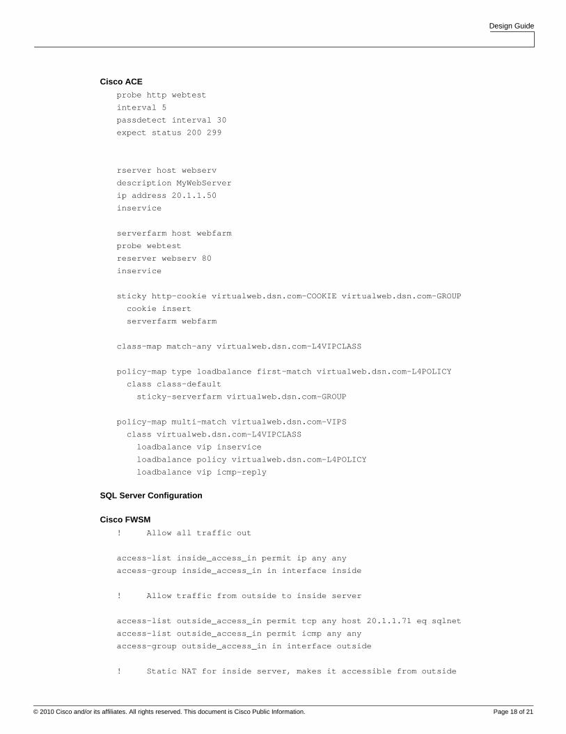
Cisco ACE
probe http webtest
interval 5
passdetect interval 30
expect status 200 299
rserver host webserv
description MyWebServer
ip address 20.1.1.50
inservice
serverfarm host webfarm
probe webtest
reserver webserv 80
inservice
sticky http-cookie virtualweb.dsn.com-COOKIE virtualweb.dsn.com-GROUP
cookie insert
serverfarm webfarm
class-map match-any virtualweb.dsn.com-L4VIPCLASS
policy-map type loadbalance first-match virtualweb.dsn.com-L4POLICY
class class-default
sticky-serverfarm virtualweb.dsn.com-GROUP
policy-map multi-match virtualweb.dsn.com-VIPS
class virtualweb.dsn.com-L4VIPCLASS
loadbalance vip inservice
loadbalance policy virtualweb.dsn.com-L4POLICY
loadbalance vip icmp-reply
SQL Server Configuration
Cisco FWSM
! Allow all traffic out
access-list inside_access_in permit ip any any
access-group inside_access_in in interface inside
! Allow traffic from outside to inside server
access-list outside_access_in permit tcp any host 20.1.1.71 eq sqlnet
access-list outside_access_in permit icmp any any
access-group outside_access_in in interface outside
! Static NAT for inside server, makes it accessible from outside

Design Guide
© 2010 Cisco and/or its affiliates. All rights reserved. This document is Cisco Public Information. Page 19 of 21
static (inside,outside) 20.1.1.71 20.1.1.71 netmask 255.255.255.255
! Functional inspection to make some protocols work through firewall/nat
class-map inspection_default
match default-inspection-traffic
policy-map global_policy
class inspection_default
inspect sqlnet
inspect ftp
Cisco ACE
probe tcp sqltest
port 1433
interval 5
passdetect interval 30
probe http webtest
interval 5
passdetect interval 30
expect status 200 299
rserver host sqlserv
description MySQLServer
ip address 20.1.1.60
inservice
rserver host webserv
description MyWebServer
ip address 20.1.1.61
inservice
serverfarm host sqlfarm
probe sqltest
rserver sqlserv 1433
inservice
serverfarm host webfarm
probe webtest
rserver webserv 80
inservice
sticky http-cookie virtualweb.dsn.com-COOKIE virtualweb.dsn.com-GROUP
cookie insert
serverfarm webfarm
sticky ip-netmask 255.255.255.255 address source virtualsql.dsn.com-SQL-STICKY
serverfarm sqlfarm
class-map match-any virtualsql.dsn.com-SQLVIP
class-map match-any virtualweb.dsn.com-L4VIPCLASS

Design Guide
© 2010 Cisco and/or its affiliates. All rights reserved. This document is Cisco Public Information. Page 20 of 21
policy-map type loadbalance first-match virtualsql.dsn.com-SQLPOLICY
class class-default
sticky-serverfarm virtualsql.dsn.com-SQL-STICKY
policy-map type loadbalance first-match virtualweb.dsn.com-L4POLICY
class class-default
sticky-serverfarm virtualweb.dsn.com-GROUP
policy-map multi-match virtualsql.dsn.com-VIPS
class virtualsql.dsn.com-SQLVIP
loadbalance vip inservice
loadbalance policy virtualsql.dsn.com-SQLPOLICY
loadbalance vip icmp-reply active
policy-map multi-match virtualweb.dsn.com-VIPS
class virtualweb.dsn.com-L4VIPCLASS
loadbalance vip inservice
loadbalance policy virtualweb.dsn.com-L4POLICY
loadbalance vip icmp-reply
Microsoft Exchange Configuration
Cisco FWSM
! Allow all traffic out
access-list inside_access_in permit ip any any
access-group inside_access_in in interface inside
! Allow traffic from outside to inside server
access-list outside_access_in permit tcp any host 20.1.1.72 eq https
access-list outside_access_in permit tcp any host 20.1.1.72 eq smtp
access-list outside_access_in permit udp any host 20.1.1.72 eq domain
access-list outside_access_in permit icmp any any
access-group outside_access_in in interface outside
! Static NAT for inside server, makes it accessible from outside
static (inside,outside) 20.1.1.72 20.1.1.72 netmask 255.255.255.255
! Functional inspection to make some protocols work through firewall/nat
class-map inspection_default
match default-inspection-traffic
policy-map global_policy
class inspection_default
inspect sqlnet
inspect ftp
Design Guide
© 2010 Cisco and/or its affiliates. All rights reserved. This document is Cisco Public Information. Page 21 of 21
Printed in USA C07-606204-00 06/10