Embed Size (px)
Citation preview

G11
GRILLES AND REGISTERS
G
GRILLES A
ND
REG
ISTERS
Industrial SupplyThe industrial supply grilles and registers have contouredairfoil blades that are extruded aluminum and areavailable with either 1 1/2" (38) or 3" (76) blade spacing.The heavy gauge, 1 1/4" (32) frame includes reinforcedand staked mitered corners.• Double Deflection 1 1/2" (38) Blade Spacing – Models 81DV, 81DH See page G1583" (76) Blade Spacing – Models 813DV, 813DH See page G158Suffix '-O' adds a steel OBD• Single Deflection 1 1/2" (38) Blade Spacing – Models 81SV, 81SH See page G1583" (76) Blade Spacing – Models 813SV, 813SH See page G158Suffix '-O' adds a steel OBD• Gang Operated – Models 81GDV, 81GDH See page G158Suffix '-O' adds a steel OBD
Modular Core – Industrial SupplyNailor has incorporated the features of the 8100 Series(double deflection) industrial supply grilles with analuminum modular frame, which allows for extradirectional flow flexibility. Up to four modules are availablein specific sizes from 8" x 8" to 15" x 15" (203 x 203 to 381x 381).Models 81MG1, 81MG2, 81MG3, 81MG4 See page G165Suffix '-O' adds a steel OBD
Models 813SH-O, 813DV
Model 81MG3
Drum LouversThese extruded aluminum drum louvers are appropriatewhen high volumes of air are used and in spot heatingand cooling applications. A split-vane style and a poleoperating bracket are available.Models 45DL1, 45DL2 See page G151Suffix '-O' adds a steel OBD
Lattice FaceLattice face grilles are available in heavy gaugealuminum, steel and stainless steel construction with aselection of hole patterns to choose from. Countersunkscrew holes and mounting screws are optional.Aluminum – Model 51LG See page G170Steel – Model 61LG See page G170Stainless Steel – Model 67LG See page G170
Models 45DL1, 45DL2
Model 61LG75

G
GRILLES A
ND
REG
ISTERS
G151
DRUM LOUVERS
FEATURES:• Rotating adjustable cylindrical drumsare tightly pivoted to the end caps of the1 1/4" (32) wide border frames and aresupplied with 3/16" (5) diameter facescrew mounting holes and a perimeterframe gasket.• Felt seal around the rotating drum tominimize air leakage.• Paddle-size deflection vanes are rearpivoted on nylon bushings in therectangular drum opening, and tightlyhold deflection angle settingsregardless of duct velocity and pressurelevels.• The Drum Louver is rated for use atcapacities ranging from 100 to 14,000cfm.
• Sizes available are 6" (152), 10"(254), 12" (305) and 15" (381) in heightand 9" (229) through 72" (1829) inwidth. See dimensional data on nextpage for available increments.• An optional pole operator is availableto allow directional control of airflow inremote mounted locations.• An optional opposed blade damper isavailable with a screwdriver slotoperator accessible through thedischarge opening. However, they arenot recommended where the staticpressure drop across the drum louverexceeds 0.25" w.g.. Under theseconditions balancing should beperformed by a remote damper installedin the take-off.
• High quality, extruded aluminumconstruction.• AW Appliance White baked enamelfinish is standard. Other finishes areavailable.
Model Series 45DL Drum Louvers are supply air outlets engineered for use in cooling, heating, and ventilating applicationsrequiring long throws and accurate directional control of conditioned air in large enclosed spaces where ductwork cannot bebrought close to the occupants. Typically, they are used in sport arenas, exhibition halls, manufacturing and industrial plants, officebuilding entrances, lobbies, shopping malls and atriums.Model Series 45DL Drum Louvers are designed to provide jet or diffused air patterns in ceiling, sidewall and exposed ductapplications. In sidewall and exposed duct installations, the Model Series 45DL can be mounted vertically or horizontally. Model Series 45DL are ideal for vertical spot cooling or heating when mounted in the ceiling or on the bottom of exposedductwork. They are capable of supplying straight flow primary air jet streams at 0° deflection for long throws, and a diffused patternof primary air at 15° and 30° deflections for shorter throws and greater spread. There is a difference of approximately 35 percentin throw between jet and diffused air patterns. The cylindrical drum enables primary air to be directed horizontally or verticallywithin a 60° arc, and when coupled with the adjustable louvers provides accurate directional control of primary air for people, plantor product.Model 45DL2 features a split-vane option. The individual vanes are separated by a central divider and may be adjusted inopposite directions to produce a 'counter flow' air pattern. This creates more rapid mixing of primary and room air and a furtherreduction in the length of throw. With this option you therefore have the utmost versatility for all applications.
Models:45DL1 Single Vanes45DL2 Split Vanes• Suffix '-O' adds a steel opposed
blade damper
DRUM LOUVERS45DL SERIES• HIGH CAPACITY• LONG THROW• ALUMINUM CONSTRUCTION
Models 45DL1-O and 45DL2

1 1/4"(32)
30°
30°
FELT SEAL ADJUSTABLEVANES
1/2" (13)
D
E
OPTIONALOPPOSED
BLADEDAMPER
GASKETAROUNDFRAME
A =OVERALLHEIGHT
B C
F
9/32" (7)
1 3/4"(44)
3/16" (5) HOLES ON CENTERLINE ON X 6 SIZES ONLY
H =DUCT
HEIGHTG
DUCT WIDTH = LISTED WIDTH + 1 1/8" (29)
OVERALL WIDTH = LISTED WIDTH + 2 3/4" (70)
3 1/4"(83)
OPTIONALPOLE
OPERATOR
FELT SEAL ADJUSTABLEVANES
A =OVERALLHEIGHT
F
3/16" (5) HOLES ON CENTERLINE ON X 6 SIZES ONLY
G
DUCT WIDTH = LISTED WIDTH + 1 1/8" (29)
OVERALL WIDTH = LISTED WIDTH + 2 3/4" (70)
C
CENTRALDIVIDER
1/2" (13)
B
HEIGHT 6 10 12 15NO. OF NO. OF NO. OF NO. OFW x H VANES W x H VANES W x H VANES W x H VANES
9 x 6 2 18 x 10 2 18 x 12 2 18 x 15 212 x 6 3 24 x 10 3 24 x 12 3 24 x 15 318 x 6 5 30 x 10 4 30 x 12 4 30 x 15 424 x 6 7 36 x 10 5 36 x 12 5 36 x 15 530 x 6 9 42 x 10 6 42 x 12 6 42 x 15 636 x 6 11 48 x 10 7 48 x 12 7 48 x 15 748 x 6 15 54 x 10 8 54 x 12 8 54 x 15 854 x 6 17 60 x 10 9 60 x 12 9 60 x 15 960 x 6 19 72 x 10 11 72 x 12 11 72 x 15 11
H 6 7/8 (175) 10 1/2 (267) 12 1/2 (318) 15 1/2 (384)A 8 1/2 (216) 12 1/8 (308) 14 1/8 (359) 17 1/8 (435)B 3 3/8 (86) 5 3/8 (137) 6 3/8 (162) 9 3/8 (238)C 3 (76) 6 (152) 6 (152) 6 (152)D 1 11/16 (43) 2 21/32 (67) 3 9/32 (83) 3 3/4 (95)E 4 1/2 (114) 6 1/4 (159) 7 1/8 (181) 8 3/4 (222)F 6 (152) 6 (152) 6 (152) 6 (152)G — 6 (152) 6 (152) 9 (229)
DIM
ENSI
ON
SIN
INC
HES
(MM
)LI
STED
SIZ
ESNO
MIN
ALW
IDTH
x H
EIG
HTIN
INC
HES
Model45DL2CentralDivider
Model45DL1
G152
DRUM LOUVERS
Dimensional DataModel Series 45DL Drum Louvers
G
GRIL
LES
AN
D R
EGIS
TERS

HOW TO SPECIFY OR TO ORDER(Show complete Model Number and Size, unless "Default" is desired).
G153
DRUM LOUVERS
G
GRILLES A
ND
REG
ISTERS
Drum Louvers – Model Series 45DL
45DL1 - O - 24 x 10 - S - AW - A - —
MODEL- Single Vanes 45DL1- Split Vanes 45DL2
DAMPER (OBD)- Steel Damper O- No Damper —
WIDTH x HEIGHTinches (mm) x inches (mm)
ACCESSORIES- None (default) —- Pole Operator Bracket POB
FASTENING- Screw Holes (default) A
FINISH- Appliance White (default) AW- Aluminum AL- Special Custom Color SP
FRAME / BORDER TYPE- Surface Mount (default) S
Notes:1. Damper not recommended where the static pressure drop across the drum louver exceeds 0.25" w.g. 2. For a standard drum louver with no special requirements, specification is only required as far as the damper selection. The"default" will automatically be selected. For example, a split vanes drum louver and damper is Model 45DL2-O. Unit will besupplied with screw holes and AW Appliance White baked enamel finish.
SUGGESTED SPECIFICATION:Furnish and install Nailor Model (select one) 45DL1 or 45DL2 Drum Louvers of the type and size as shown on the plans andair distribution schedules. The louver is to be manufactured from extruded aluminum and have a cylindrical adjustable drumthat rotates. The blades are to have a paddle like profile that pivot on nylon bushings. A perimeter gasket is to be includedaround the frame and a felt seal is to be around the drum. The finish shall be AW Appliance White baked enamel (optionalfinishes are available).(Optional) An opposed blade damper, constructed of heavy gauge corrosion-resistant steel and operable from the face of thegrille, shall be provided with all units.The manufacturer shall provide published performance data for the louver, which shall be tested in accordance withANSI/ASHRAE Standard 70 – 2006.

Performance DataModel Series 45DL • 6" (152) Drum Louver
SIZENeck Velocity, FPM 280 420 560 700 840 980 1120 1400 1680VP .005 .011 .020 .031 .044 .060 .078 .122 .176Airflow, CFM 105 158 210 263 315 368 420 525 630TP .022 .06 .10 .16 .21 .30 .40 .60 .90
9 x 6 T 7-10-18 10-14-24 13-18-30 15-21-35 17-23-40 20-28-46 22-30-50 26-35-56 30-40-66NC — — — 22 27 32 36 41 46Airflow, CFM 140 210 280 350 420 490 560 700 840TP .03 .06 .10 .16 .23 .32 .40 .63 .90
12 x 6 T 8-11-18 12-16-27 16-21-34 18-24-40 20-26-45 23-31-50 25-34-55 30-40-66 35-47-76NC — — — 23 28 33 37 42 47Airflow, CFM 210 315 420 525 630 735 840 1050 1260TP .022 .06 .10 .16 .24 .33 .40 .60 .90
18 x 6 T 12-16-27 17-22-36 21-27-45 25-32-52 28-37-62 31-42-70 34-46-76 42-54-90 48-62-101NC — — — 24 29 34 38 43 49Airflow, CFM 280 420 560 700 840 980 1120 1400 168TP .03 .06 .10 .16 .24 .32 .40 .63 .90
24 x 6 T 16-21-33 21-28-44 26-33-54 31-40-64 35-45-72 38-50-80 42-52-88 48-64-100 52-71-110NC — — — 26 31 36 40 47 52Airflow, CFM 350 525 700 875 1050 1225 1400 1750 210TP .022 .06 .10 .16 .21 .32 .40 .63 .90
30 x 6 T 19-24-38 25-32-50 30-38-60 35-45-70 39-50-78 43-56-86 47-60-94 54-70-100 60-78-120NC — — 20 27 32 37 41 48 53Airflow, CFM 420 630 840 1050 1260 1470 1680 2100 2520TP .03 .06 .10 .16 .22 .30 .40 .60 .90
36 x 6 T 20-26-40 26-35-54 32-41-64 36-46-74 40-52-82 44-55-90 48-62-100 54-72-115 62-80-130NC — — 21 28 33 38 42 49 55Airflow, CFM 565 848 1130 1412 1695 1978 2260 2825 3390TP .03 .06 .10 .16 .24 .32 .40 .63 .90
48 x 6 T 24-31-39 31-42-63 37-49-76 44-56-89 48-62-100 50-70-110 58-74-120 65-82-130 74-95-150NC — — 22 29 34 39 43 50 56Airflow, CFM 700 1050 1400 1750 2100 2450 2800 3500 4200TP .03 .06 .10 .16 .24 .32 .40 .63 .90
60 x 6 T 28-36-54 36-46-66 43-55-84 49-63-96 52-70-110 60-75-120 65-82-130 75-90-150 84-105-170NC — — 23 30 35 40 44 51 57
CFM - cubic feet per minuteFPM - feet per minute velocityTP - total pressure - inches w.g.VP - velocity pressure - inches w.g.T - throw in feetNC - Noise Criteria (values) based on
10 dB room absorption, re 10-12
watts.
Performance Notes:1. Throws are given at 150, 100 and50 fpm terminal velocities underisothermal conditions.2. Total pressure, throw and NC arebased on 45DL1 at 0° deflection.Correction factors for other conditionsare listed below.
3. Data derived from tests conductedin accordance with ANSI/ASHRAEStandard 70 – 2006.
Model Deflection TP Throw NC15° x 1.5 x .85 + 445DL1 30° x 1.9 x .73 + 90° x 1.3 - -
45DL2 15° x 1.7 x .85 + 430° x 2.2 x .73 + 9
Correction Factor
G154
DRUM LOUVERS
G
GRIL
LES
AN
D R
EGIS
TERS
G
GRILLES A
ND
REG
ISTERS
G155
DRUM LOUVERS
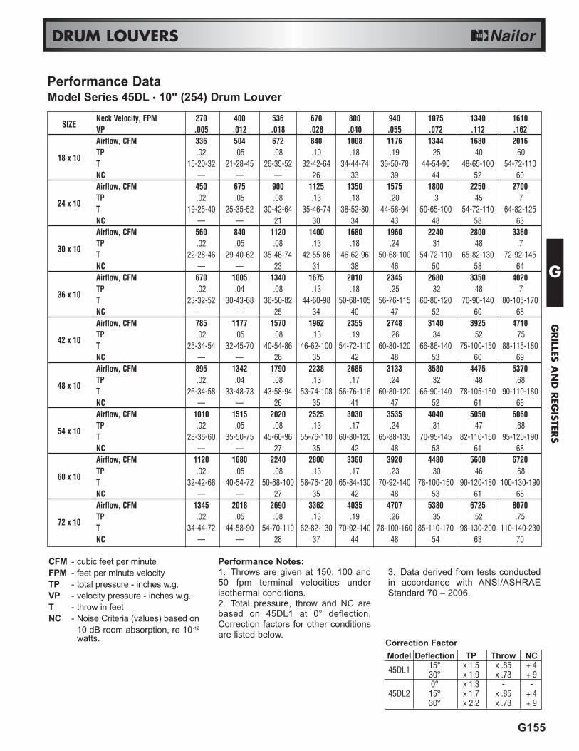
Performance DataModel Series 45DL • 10" (254) Drum Louver
CFM - cubic feet per minuteFPM - feet per minute velocityTP - total pressure - inches w.g.VP - velocity pressure - inches w.g.T - throw in feetNC - Noise Criteria (values) based on
10 dB room absorption, re 10-12
watts.
Performance Notes:1. Throws are given at 150, 100 and50 fpm terminal velocities underisothermal conditions.2. Total pressure, throw and NC arebased on 45DL1 at 0° deflection.Correction factors for other conditionsare listed below.
3. Data derived from tests conductedin accordance with ANSI/ASHRAEStandard 70 – 2006.
Model Deflection TP Throw NC15° x 1.5 x .85 + 445DL1 30° x 1.9 x .73 + 90° x 1.3 - -
45DL2 15° x 1.7 x .85 + 430° x 2.2 x .73 + 9
Correction Factor
SIZENeck Velocity, FPM 270 400 536 670 800 940 1075 1340 1610VP .005 .012 .018 .028 .040 .055 .072 .112 .162Airflow, CFM 336 504 672 840 1008 1176 1344 1680 2016TP .02 .05 .08 .10 .18 .19 .25 .40 .60
18 x 10T 15-20-32 21-28-45 26-35-52 32-42-64 34-44-74 36-50-78 44-54-90 48-65-100 54-72-110NC — — — 26 33 39 44 52 60Airflow, CFM 450 675 900 1125 1350 1575 1800 2250 2700TP .02 .05 .08 .13 .18 .20 .3 .45 .7
24 x 10T 19-25-40 25-35-52 30-42-64 35-46-74 38-52-80 44-58-94 50-65-100 54-72-110 64-82-125NC — — 21 30 34 43 48 58 63Airflow, CFM 560 840 1120 1400 1680 1960 2240 2800 3360TP .02 .05 .08 .13 .18 .24 .31 .48 .7
30 x 10T 22-28-46 29-40-62 35-46-74 42-55-86 46-62-96 50-68-100 54-72-110 65-82-130 72-92-145NC — — 23 31 38 46 50 58 64Airflow, CFM 670 1005 1340 1675 2010 2345 2680 3350 4020TP .02 .04 .08 .13 .18 .25 .32 .48 .7
36 x 10T 23-32-52 30-43-68 36-50-82 44-60-98 50-68-105 56-76-115 60-80-120 70-90-140 80-105-170NC — — 25 34 40 47 52 60 68Airflow, CFM 785 1177 1570 1962 2355 2748 3140 3925 4710TP .02 .05 .08 .13 .19 .26 .34 .52 .75
42 x 10T 25-34-54 32-45-70 40-54-86 46-62-100 54-72-110 60-80-120 66-86-140 75-100-150 88-115-180NC — — 26 35 42 48 53 60 69Airflow, CFM 895 1342 1790 2238 2685 3133 3580 4475 5370TP .02 .04 .08 .13 .17 .24 .32 .48 .68
48 x 10T 26-34-58 33-48-73 43-58-94 53-74-108 56-76-116 60-80-120 66-90-140 78-105-150 90-110-180NC — — 26 35 41 47 52 61 68Airflow, CFM 1010 1515 2020 2525 3030 3535 4040 5050 6060TP .02 .05 .08 .13 .17 .24 .31 .47 .68
54 x 10T 28-36-60 35-50-75 45-60-96 55-76-110 60-80-120 65-88-135 70-95-145 82-110-160 95-120-190NC — — 27 35 42 48 53 61 68Airflow, CFM 1120 1680 2240 2800 3360 3920 4480 5600 6720TP .02 .05 .08 .13 .17 .23 .30 .46 .68
60 x 10T 32-42-68 40-54-72 50-68-100 58-76-120 65-84-130 70-92-140 78-100-150 90-120-180 100-130-190NC — — 27 35 42 48 53 61 68Airflow, CFM 1345 2018 2690 3362 4035 4707 5380 6725 8070TP .02 .05 .08 .13 .19 .26 .35 .52 .75
72 x 10T 34-44-72 44-58-90 54-70-110 62-82-130 70-92-140 78-100-160 85-110-170 98-130-200 110-140-230NC — — 28 37 44 48 54 63 70
G156
DRUM LOUVERS
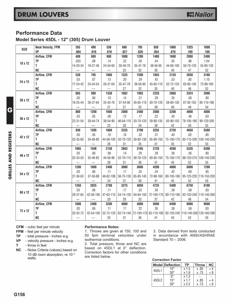
SIZENeck Velocity, FPM 265 400 530 660 795 930 1060 1325 1600VP .004 .010 .018 .027 .039 .054 .070 .109 .160Airflow, CFM 400 600 800 1000 1200 1400 1600 2000 2400TP .033 .08 .14 .22 .30 .44 .55 .86 1.04
18 x 12T 14-20-34 19-27-46 24-34-60 30-40-70 35-47-78 38-56-95 44-60-100 50-70-120 55-80-130NC — — — 25 32 36 40 47 52Airflow, CFM 530 795 1060 1325 1590 1855 2120 2650 3180TP .03 .07 .13 .20 .29 .42 .53 .82 1.10
24 x 12T 17-24-42 24-34-54 26-37-64 35-47-78 38-56-95 45-65-110 52-72-120 65-85-140 72-98-160NC — — — 27 32 35 40 46 52Airflow, CFM 665 998 1330 1662 1993 2328 2660 3324 3990TP .03 .06 .10 .14 .21 .28 .35 .58 .80
30 x 12T 18-25-44 26-37-64 33-45-76 37-54-90 45-65-110 50-70-120 58-80-130 67-92-155 85-110-180NC — — 21 27 32 38 40 48 54Airflow, CFM 800 1200 1600 2000 2400 2800 3200 4000 4800TP .03 .05 .08 .12 .17 .22 .30 .46 .63
36 x 12T 22-31-54 30-44-74 38-54-90 46-64-110 50-70-120 58-80-135 65-90-150 78-105-180 90-120-200NC — — 22 28 34 38 42 50 55Airflow, CFM 930 1395 1860 2325 2790 3255 3720 4650 5580TP .03 .05 .10 .16 .22 .31 .40 .62 .80
42 x 12T 25-35-60 34-46-80 44-58-100 50-70-120 58-80-130 65-90-150 75-100-170 85-115-200 100-140-230NC — — 26 31 35 41 45 52 55Airflow, CFM 1065 1598 2130 2663 3195 3728 4260 5326 6390TP .03 .06 .08 .14 .20 .28 .36 .56 .80
48 x 12T 25-33-53 35-46-82 44-56-96 52-70-115 58-78-125 60-95-150 75-100-170 88-120-210 100-140-230NC — — 26 31 36 41 45 52 55Airflow, CFM 1200 1800 2400 3000 3600 4200 4800 6000 7200TP .03 .06 .11 .17 .25 .34 .42 .68 .95
54 x 12T 27-36-63 37-50-88 46-62-108 56-75-130 65-85-145 72-98-160 80-105-180 95-125-220 110-150-250NC — — 24 31 36 41 45 52 55Airflow, CFM 1350 2025 2700 3375 4050 4725 5400 6750 8100TP .03 .06 .11 .17 .22 .30 .38 .58 .83
60 x 12T 28-37-65 42-56-100 47-63-110 54-74-130 64-84-150 72-100-170 80-110-190 92-120-240 110-140-260NC — — 20 28 33 37 42 48 54Airflow, CFM 1600 2400 3200 4000 4800 5600 6400 8000 9600TP .03 .06 .11 .17 .22 .30 .38 .58 .83
72 x 12T 32-42-72 42-54-100 52-72-120 62-74-140 72-100-170 82-110-190 92-120-240 110-140-260 120-160-290NC — — 25 31 36 41 45 52 55
Performance DataModel Series 45DL • 12" (305) Drum Louver
CFM - cubic feet per minuteFPM - feet per minute velocityTP - total pressure - inches w.g.VP - velocity pressure - inches w.g.T - throw in feetNC - Noise Criteria (values) based on
10 dB room absorption, re 10-12
watts.
Performance Notes:1. Throws are given at 150, 100 and50 fpm terminal velocities underisothermal conditions.2. Total pressure, throw and NC arebased on 45DL1 at 0° deflection.Correction factors for other conditionsare listed below.
3. Data derived from tests conductedin accordance with ANSI/ASHRAEStandard 70 – 2006.
Model Deflection TP Throw NC15° x 1.5 x .85 + 445DL1 30° x 1.9 x .73 + 90° x 1.3 - -
45DL2 15° x 1.7 x .85 + 430° x 2.2 x .73 + 9
Correction Factor
G
GRIL
LES
AN
D R
EGIS
TERS

G
GRILLES A
ND
REG
ISTERS
G157
DRUM LOUVERS
SIZENeck Velocity, FPM 312 470 625 780 935 1090 1250 1560 1870VP .006 .014 .024 .038 .054 .074 .097 .152 .218Airflow, CFM 585 878 1170 1463 1755 2048 2340 2925 3510TP .02 .05 .09 .14 .21 .27 .36 .55 .82
18 x 15T 15-21-36 21-30-52 28-40-67 32-45-75 37-51-94 42-59-100 47-65-110 58-82-140 66-92-160NC — — 22 28 33 38 42 49 54Airflow, CFM 780 1170 1560 1950 2340 2730 3120 3900 4680TP .02 .04 .08 .12 .19 .25 .34 .50 .68
24 x 15T 18-25-45 25-35-62 33-46-80 40-55-100 45-64-110 54-75-130 60-84-140 70-100-170 80-110-190NC — — 22 28 34 39 43 50 55Airflow, CFM 975 1463 1950 2438 2925 3413 3900 4875 5850TP .02 .05 .08 .13 .20 .25 .34 .50 .72
30 x 15T 21-30-52 30-42-74 38-54-97 45-64-110 54-75-130 60-84-140 66-94-160 80-110-190 92-130-225NC — — 22 29 35 40 44 51 56Airflow, CFM 1170 1755 2340 2925 3510 4095 4680 5850 7020TP .025 .05 .10 .15 .20 .26 .36 .55 .78
36 x 15T 23-33-58 32-45-80 40-56-100 47-65-110 56-76-130 62-88-150 70-100-170 80-110-190 110-130-220NC — — 25 32 37 42 45 52 58Airflow, CFM 1365 2048 2730 3413 4095 4778 5460 6825 8190TP .02 .05 .10 .15 .22 .30 .38 .60 .85
42 x 15T 27-37-66 38-52-92 47-65-110 56-76-130 62-88-150 70-100-170 80-110-190 100-130-220 110-150-260NC — — 25 31 36 41 44 51 57Airflow, CFM 1565 2348 3130 3913 4695 5478 6260 7825 9390TP .02 .05 .08 .13 .18 .25 .33 .50 .8
48 x 15T 28-40-70 40-55-100 50-70-120 60-82-140 70-98-160 80-110-190 90-130-220 110-150-260 120-180-300NC — — 25 32 37 42 45 52 58Airflow, CFM 1760 2640 3520 4400 5280 6160 7040 8800 10560TP .025 .05 .10 .16 .21 .30 .40 .65 .85
54 x 15T 30-44-75 44-60-110 54-78-130 65-90-160 75-105-180 90-120-210 100-135-240 120-160-280 130-180-310NC — — 26 32 37 42 45 52 58Airflow, CFM 1950 2925 3900 4875 5850 6825 7800 9750 11700TP .02 .045 .08 .12 .17 .25 .30 .50 .75
60 x 15T 34-45-76 44-60-110 54-78-130 65-90-160 75-105-180 90-120-210 100-135-240 120-160-280 130-180-310NC — — 26 33 38 43 46 53 59Airflow, CFM 2345 3518 4690 5863 7035 8208 9380 11725 14070TP .02 .05 .10 .14 .20 .26 .33 .55 .80
72 x 15T 37-50-90 50-70-120 62-88-160 76-100-190 90-125-220 100-140-250 115-150-280 130-190-330 160-220-400NC — — 27 34 39 44 47 54 60
Performance DataModel Series 45DL • 15" (381) Drum Louver
CFM - cubic feet per minuteFPM - feet per minute velocityTP - total pressure - inches w.g.VP - velocity pressure - inches w.g.T - throw in feetNC - Noise Criteria (values) based on
10 dB room absorption, re 10-12
watts.
Performance Notes:1. Throws are given at 150, 100 and50 fpm terminal velocities underisothermal conditions.2. Total pressure, throw and NC arebased on 45DL1 at 0° deflection.Correction factors for other conditionsare listed below.
3. Data derived from tests conductedin accordance with ANSI/ASHRAEStandard 70 – 2006.
Model Deflection TP Throw NC15° x 1.5 x .85 + 445DL1 30° x 1.9 x .73 + 90° x 1.3 - -
45DL2 15° x 1.7 x .85 + 430° x 2.2 x .73 + 9
Correction Factor

G172
GRILLE AND REGISTER OPTIONS AND ACCESSORIES
PRODUCT OVERVIEWOPTIONS AND ACCESSORIES FORGRILLES AND REGISTERS
Model PFSub-frame
Model OBDOpposed Blade Damper
Steel, Neck Mount
Model DFADrywall/Plaster Frame
Surface MountCeiling Adaptor
FASTENING AND MOUNTING FRAMES• Up to four methods of fastening available for most
models.• Sub-frame available for professionally finished
openings.• Surface mount adaptor frame for plaster and sheet
rock ceilings.• Panel mounting available to suit architectural ceiling
systems.
OPTIONS• A selection of optional items that are available on
grilles and registers.• Information on custom sizing for special applications.
FINISHES• Selection of standard and non-standard finishes to
choose from.• Baked enamel paint in custom colors to suit architect.• Anodizing of aluminum products.
AIR BALANCING DEVICES• Opposed blade dampers for every application.• Volume extractors.Effective air balancing of an HVAC System requires thecorrect selection, specification and installation of the rightproduct to suit the system design.Nailor offers a comprehensive range of models andoptions to cover all applications.Nailor balancing devices are:• Easy to select and specify. Many items can be
supplied as factory mounted or packaged accessorieson grilles and registers.
• Designed to offer a smooth, accurate and predictableresponse during adjustment for precise air metering.
• Designed to provide quick access and adjustment.• Engineered with attention to optimizing airflow in order
to minimize noise, turbulence and pressure drop.
Model OBDDOpposed Blade Damper
Steel, Duct Mount
ModelEX-1
VolumeExtractor
ModelEX-3
VolumeExtractor
G
GRIL
LES
AN
D R
EGIS
TERS

G
GRILLES A
ND
REG
ISTERS
G173
GRILLE AND REGISTER OPTIONS AND ACCESSORIES
Type A Screw Fastening (External)Standard method of fastening for all Nailor grilles andregisters in surface mount applications. All Nailorgrilles and registers are supplied this way unlessspecified otherwise. Universal application for allmodels and cost effective installation.Screw holes are countersunk in the frame for mostmodels to provide an aesthetically pleasingappearance and are sized for #8 x 1 1/2" (38) oval-head screws which are supplied from the factorypacked with each grille or register and are painted tomatch the specified finish.
Type C Concealed MountingGrilles and registers are supplied with concealedmounting straps (at additional cost) which permitsurface mounting with concealed screws, allowing aclean frame appearance. The bracket attached to theback of the grille screws to an adjustable mountingstrap which can either be secured directly to the ductwall or hooked into a hem formed in the end of theduct. Not available on return grilles with 1/2" (13)spacing and a fixed angled blade deflection.Maximum size: 36" x 36" (914 x 914).
Type D Screw Fastening (Concealed)Screw holes are provided in the neck of the grille orregister frame. Screws are field installed at an anglethrough the grille frame and into the ductwork,providing a clean frame appearance. Installation ismore difficult than Type A due to the spaceconstriction between the grille blades. Care must betaken not to bend or scratch the grille. Notrecommended on return air grilles with a fixed angledblade deflection as accessibility to screw holes isgreatly restricted.
Type NF Narrow FrameAn optional reduced 1" (25) wide narrow border frameis available on most aluminum models to satisfyarchitectural considerations.See individual models for availability.
DUCT
Type A Screw Fastening (external)Standard
HEMMEDDUCT
Type C Concealed Mounting
DUCT
Type D Screw Fastening (concealed)
Fastening and Border Frames
1" (25)
1 1/4"(32)OR
1 13/16"(46)
3/4" (19)OVERLAPMARGIN
NF Narrow Frame
G174
GRILLE AND REGISTER OPTIONS AND ACCESSORIES
PF = LISTED SIZE
LISTED SIZE + 2 1/4" (57)
5/16" (8)
PF = LISTED SIZE
DUCT = LISTED SIZE + 1/4" (6)
DUCT = LISTED SIZE + 1/4" (6)
Model PF Plaster Frame
Surface Mount Recessed
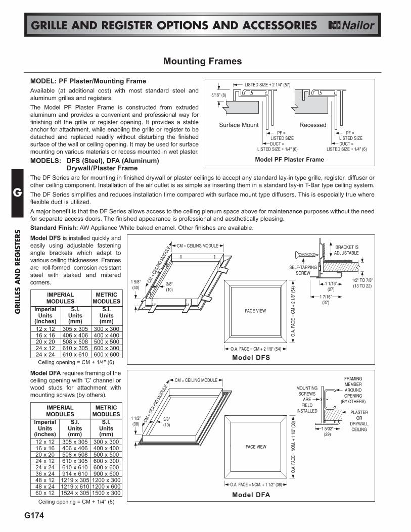
MODEL: PF Plaster/Mounting FrameAvailable (at additional cost) with most standard steel andaluminum grilles and registers. The Model PF Plaster Frame is constructed from extrudedaluminum and provides a convenient and professional way forfinishing off the grille or register opening. It provides a stableanchor for attachment, while enabling the grille or register to bedetached and replaced readily without disturbing the finishedsurface of the wall or ceiling opening. It may be used for surfacemounting on various materials or recess mounted in wet plaster.
1 5/8"(40)
CM = CEILING MODULE
CM =
CEI
LING
MODU
LE
3/8"(10)
Model DFS
Mounting Frames
Model DFA
BRACKET ISADJUSTABLE
SELF-TAPPINGSCREW
1 7/16"(37)
1/2" TO 7/8"(13 TO 22)1 1/16"
(27)
FRAMINGMEMBERAROUNDOPENING
(BY OTHERS)
MOUNTINGSCREWS
AREFIELD
INSTALLED
1 5/32"(29)
PLASTEROR
DRYWALLCEILING
Model DFA requires framing of theceiling opening with 'C' channel orwood studs for attachment withmounting screws (by others).
Model DFS is installed quickly andeasily using adjustable fasteningangle brackets which adapt tovarious ceiling thicknesses. Framesare roll-formed corrosion-resistantsteel with staked and miteredcorners.
MODELS: DFS (Steel), DFA (Aluminum)Drywall/Plaster Frame
The DF Series are for mounting in finished drywall or plaster ceilings to accept any standard lay-in type grille, register, diffuser orother ceiling component. Installation of the air outlet is as simple as inserting them in a standard lay-in T-Bar type ceiling system.The DF Series simplifies and reduces installation time compared with surface mount type diffusers. This is especially true whereflexible duct is utilized. A major benefit is that the DF Series allows access to the ceiling plenum space above for maintenance purposes without the needfor separate access doors. The finished appearance is professional and aesthetically pleasing.Standard Finish: AW Appliance White baked enamel. Other finishes are available.
IMPERIAL METRICMODULES MODULES
Imperial S.I. S.I.Units Units Units
(inches) (mm) (mm)12 x 12 305 x 305 300 x 30016 x 16 406 x 406 400 x 40020 x 20 508 x 508 500 x 50024 x 12 610 x 305 600 x 30024 x 24 610 x 610 600 x 60036 x 24 914 x 610 900 x 60048 x 12 1219 x 305 1200 x 30048 x 24 1219 x 610 1200 x 60060 x 12 1524 x 305 1500 x 300Ceiling opening = CM + 1/4" (6)
FACE VIEW
O.A. FACE = CM + 2 1/8" (54)
O.A
. FAC
E =
CM
+ 2
1/8
" (54
)IMPERIAL METRICMODULES MODULES
Imperial S.I. S.I.Units Units Units
(inches) (mm) (mm)12 x 12 305 x 305 300 x 30016 x 16 406 x 406 400 x 40020 x 20 508 x 508 500 x 50024 x 12 610 x 305 600 x 30024 x 24 610 x 610 600 x 600Ceiling opening = CM + 1/4" (6)
CM = CEILING MODULE
CM =
CEI
LING
MOD
ULE
1 1/2"(38)
3/8"(10)
FACE VIEW
O.A. FACE = NOM. + 1 1/2" (38)
O.A
. FAC
E =
NOM
. + 1
1/2
" (38
)
G
GRIL
LES
AN
D R
EGIS
TERS

G
GRILLES A
ND
REG
ISTERS
G175
GRILLE AND REGISTER OPTIONS AND ACCESSORIES
A panel can be added to the majority of Nailor’s steel and aluminum return grilles to suitmany special architectural ceiling designs and ceiling module sizes. These panel mountgrilles are available in corrosion-resistant steel for the 6100 series steel grilles and bothaluminum and corrosion-resistant steel for the 5100 and 7100 series aluminum grilles.To specify a steel panel; add the suffix S to the end of the selected panel variant. To specifyan aluminum panel; add the suffix A to the end of the selected panel variant. e.g. If a steelpanel is required with a Spline Type ceiling module, the variant code will become SPS.
CM - 1/4" (6)
CM = CEILING MODULEType PL
CM = CEILING MODULE
CM - 1/16" (2)
13/16"(21)
Type MP
CM - 1/4" (6)
CM - 5/8" (16)
CM = CEILING MODULE
9/16" (14)
5/16"(8)
Type FP
CM - 1/16" (2)
CM = CEILING MODULE
3/8"(10)
Type SP
Note: Splines on two opposite sides.Steel lift brackets on the other two sides
Panel Mounting/Ceiling Modules
CM - 1/4" (6)
CM - 1" (25)
CM = CEILING MODULE
15/16" (24)
3/8"(10)
TEGULARCEILING
TILE
Type TL
CEILING MODULEImperial Units Metric Units
(inches) (mm)12 x 12 300 x 30024 x 12 600 x 30036 x 12 900 x 30048 x 12 1200 x 30020 x 20 500 x 50024 x 24 600 x 60036 x 24 900 x 60048 x 24 1200 x 600
Available Ceiling Module Sizes
Border Type PL: Lay-in T-BarGrille or register is mounted in an extended panel to suit standardT-Bar Lay-in Type ceilings.
Border Type SP: SplineThe grille or register is mounted in an extended panel to suit splinetype ceiling modules.
Border Type MP: Metal Pan/Snap-inThe grille or register is mounted in an extended panel to suit metalpan ceilings that have snap-in type ceiling modules.
Border Type FP: Narrow Regressed T-Bar (Fineline®)The grille or register is mounted in an extended panel that will fit anarrow regressed T-Bar ceiling grid.
Border Type TL: Tegular Type T-BarThe grille or register is mounted in a panel that will extend belowthe T-Bar ceiling grid.
The maximum grille neck sizesavailable for panel mounting will be theceiling module size selected - 3" (76).

G176
GRILLE AND REGISTER OPTIONS AND ACCESSORIES
OPTIONS:GK GasketAn optional foam gasket is available factory installed on therear of all Type S corrosion-resistant steel and aluminumsurface mount grilles and registers.Eliminates air leakage and the possibility of dirt streakingand smudging from entrainment, particularly when installedon unevenly finished surfaces such as stucco.
IS Insect Screen1/16" (2) galvanized steel mesh, factory installed.
EQT Earthquake TabsEarthquake (seismic) retaining safety tabs are available;factory installed on grilles or registers when required bylocal building code that units be independently restrainedand safety wired to supporting structure.
CUSTOM SIZING:Oversized UnitsFor specialized applications and architecturalconsiderations; certain grilles and registers can bemanufactured in single sections larger than the standardpublished maximum size at additional cost. Aspect ratio,tolerances, manufacturing capability and weight have all tobe considered by the factory prior to acceptance. Consultyour Nailor representative for specific applications.
Fractional/Hard Metric SizesNailor grilles and registers have been designed and aremanufactured to suit HVAC systems where the duct designhas been done using Imperial Units of measurement (i.e.feet and inches). The majority of Nailor grilles and registersare fabricated as standard in 1" (25) nominal incrementalunits, giving the designer great flexibility during sizingselection.At additional cost, the majority of Nailor grilles andregisters can be custom fabricated in fractional sizes forspecial applications and in Hard Metric (S.I. Units) whenthe HVAC duct design has been done using the MetricSystem.Consult your Nailor representative for availability onspecific project applications.
FINISHES:BAKED ENAMEL PAINTAW Appliance White (standard)A white finish that is currently the industry standard. Closelymatches standard finishes supplied by the majority of T-Barceiling system manufacturers. (No additional cost).AL AluminumContains suspended metal particles to give the appearance of a silver grey metallic or anodized finish. (Noadditional cost).WH Off-WhiteHas a creamy appearance. (Additional cost)BK BlackThis black has a matte finish. (Additional cost)SP SpecialThe Nailor range of grilles and registers are available inany color for special architectural consideration. Customcolors are individually mixed to match customer suppliedsamples. (Additional cost)
ACRYLICAAW Acrylic Appliance WhiteExtra protection for your grilles and registers. This colormatches the industry standard white finish. (Additionalcost).ASP Acrylic Special FinishExtra protection for your grilles and registers. Customcolors are individually mixed to match customer suppliedsamples. (Additional cost)
ALUMINUM PRODUCT FINISHESBC Brushed and Clear CoatBrushed for an enhanced appearance. (Additional cost).SA Satin (clear) AnodizedAdds a smooth satin finish to further protect the aluminumfrom corrosion. (Additional cost).
ALSO AVAILABLEMI Mill Finish(No additional cost).PPA Paint Prepared Metal (Washed only)(No additional cost).PC Prime Coat(Additional cost).
Options, Custom Sizing and Finishes
G
GRIL
LES
AN
D R
EGIS
TERS
G
GRILLES A
ND
REG
ISTERS
G177
GRILLE AND REGISTER OPTIONS AND ACCESSORIES
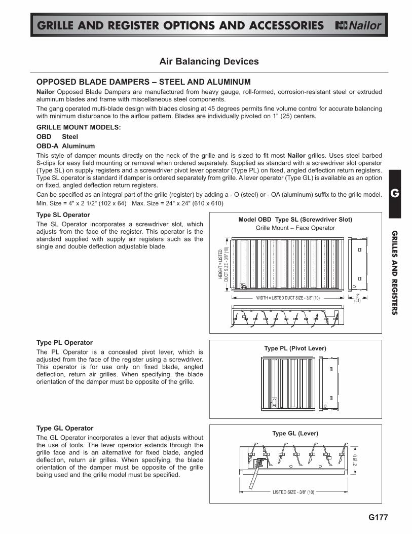
Type SL OperatorThe SL Operator incorporates a screwdriver slot, whichadjusts from the face of the register. This operator is thestandard supplied with supply air registers such as thesingle and double deflection adjustable blade.
Type PL OperatorThe PL Operator is a concealed pivot lever, which isadjusted from the face of the register using a screwdriver.This operator is for use only on fixed blade, angleddeflection, return air grilles. When specifying, the bladeorientation of the damper must be opposite of the grille.
Type GL OperatorThe GL Operator incorporates a lever that adjusts withoutthe use of tools. The lever operator extends through thegrille face and is an alternative for fixed blade, angleddeflection, return air grilles. When specifying, the bladeorientation of the damper must be opposite of the grillebeing used and the grille model must be specified.
WIDTH = LISTED DUCT SIZE - 3/8" (10)
HEIG
HT =
LISTE
DDU
CT S
IZE - 3
/8" (1
0)
2"(51)
Model OBD Type SL (Screwdriver Slot)Grille Mount – Face Operator
Air Balancing Devices
Type PL (Pivot Lever)
LISTED SIZE - 3/8" (10)
2" (
51)
Type GL (Lever)
OPPOSED BLADE DAMPERS – STEEL AND ALUMINUMNailor Opposed Blade Dampers are manufactured from heavy gauge, roll-formed, corrosion-resistant steel or extrudedaluminum blades and frame with miscellaneous steel components. The gang operated multi-blade design with blades closing at 45 degrees permits fine volume control for accurate balancingwith minimum disturbance to the airflow pattern. Blades are individually pivoted on 1" (25) centers.
GRILLE MOUNT MODELS:OBD SteelOBD-A AluminumThis style of damper mounts directly on the neck of the grille and is sized to fit most Nailor grilles. Uses steel barbed S-clips for easy field mounting or removal when ordered separately. Supplied as standard with a screwdriver slot operator(Type SL) on supply registers and a screwdriver pivot lever operator (Type PL) on fixed, angled deflection return registers.Type SL operator is standard if damper is ordered separately from grille. A lever operator (Type GL) is available as an optionon fixed, angled deflection return registers.Can be specified as an integral part of the grille (register) by adding a - O (steel) or - OA (aluminum) suffix to the grille model.Min. Size = 4" x 2 1/2" (102 x 64) Max. Size = 24" x 24" (610 x 610)
G178
GRILLE AND REGISTER OPTIONS AND ACCESSORIES
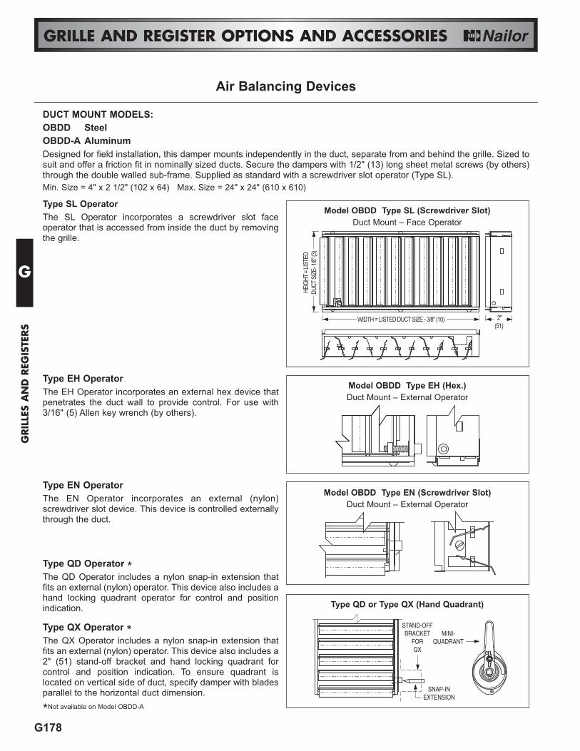
Type SL OperatorThe SL Operator incorporates a screwdriver slot faceoperator that is accessed from inside the duct by removingthe grille.
Type EH OperatorThe EH Operator incorporates an external hex device thatpenetrates the duct wall to provide control. For use with3/16" (5) Allen key wrench (by others).
Type EN OperatorThe EN Operator incorporates an external (nylon)screwdriver slot device. This device is controlled externallythrough the duct.
Type QD Operator *The QD Operator includes a nylon snap-in extension thatfits an external (nylon) operator. This device also includes ahand locking quadrant operator for control and positionindication.
Type QX Operator *The QX Operator includes a nylon snap-in extension thatfits an external (nylon) operator. This device also includes a2" (51) stand-off bracket and hand locking quadrant forcontrol and position indication. To ensure quadrant islocated on vertical side of duct, specify damper with bladesparallel to the horizontal duct dimension.
*Not available on Model OBDD-A
Type QD or Type QX (Hand Quadrant)
STAND-OFFBRACKET
FORQX
MINI-QUADRANT
SNAP-INEXTENSION
Air Balancing Devices
DUCT MOUNT MODELS:OBDD SteelOBDD-A AluminumDesigned for field installation, this damper mounts independently in the duct, separate from and behind the grille. Sized tosuit and offer a friction fit in nominally sized ducts. Secure the dampers with 1/2" (13) long sheet metal screws (by others)through the double walled sub-frame. Supplied as standard with a screwdriver slot operator (Type SL).Min. Size = 4" x 2 1/2" (102 x 64) Max. Size = 24" x 24" (610 x 610)
Model OBDD Type EH (Hex.)Duct Mount – External Operator
Model OBDD Type EN (Screwdriver Slot)Duct Mount – External Operator
WIDTH = LISTED DUCT SIZE - 3/8" (10)
HEIG
HT =
LISTE
DDU
CT SI
ZE- 1
/8" (3
) 2"(51)
Model OBDD Type SL (Screwdriver Slot)Duct Mount – Face Operator
G
GRIL
LES
AN
D R
EGIS
TERS

G
GRILLES A
ND
REG
ISTERS
G179
GRILLE AND REGISTER OPTIONS AND ACCESSORIES
GRILLE/DUCT MOUNT MODELS:OBD-SS Stainless SteelWhen ordered as part of the stainless steel grille, (using thesuffix ‘-O’ on the model number), the dampers are factorywelded to the grille frame to provide a secure non-removable connection. If the dampers are orderedseparately, they are supplied with mounting tabs. The tabsallow the dampers to be field installed onto a grille or to bemounted independently in the duct, separate from andbehind the grille.All Nailor stainless steel dampers feature a Philip’s headscrewdriver operator that is accessed through the face ofthe grille.
1 3/4"(44)
HEI
GH
T =
LIST
ED D
UC
T SI
ZE -
1/4"
(6)
WIDTH = LISTED DUCT SIZE - 1/4" (6)OPERATOR
Model OBD-SS Grille/Duct Mount – Face Operator
Air Balancing Devices
OPPOSED BLADE DAMPERS – STAINLESS STEELNailor Stainless Steel Opposed Blade Dampers feature heavy gauge, roll-formed blades and a heavy duty frame in allstainless steel construction. Type 304 stainless steel is standard with Type 316 as an available option. The gang operated multi-blade design with blades closing at 45 degrees permits fine volume control for accurate balancingwith minimum disturbance to the airflow pattern. Blades are individually pivoted on 1" (25) centers.

G180
GRILLE AND REGISTER OPTIONS AND ACCESSORIES
MODEL SERIESEX Blades on 2" centersEXD Blades on 1" centersThe Model Series EX Volume Extractors uniformly divert airfrom the main duct into the branch take-off and across theface of a grille or diffuser. Gang-operated parallel bladesavailable on 2" (51) or 1" (25) centers pivot from full open tofull closed with blades overlapping for shut-off. The curvedblade design improves airflow by reducing turbulence,thereby reducing noise and pressure drop.Specify on order: Length x Width. (Length is first dimension.Blades are parallel to width, second dimension).
FEATURES:• Material: Galvanized steel.• Minimum size: 6" x 4" (152 x 102).• Maximum size: 36" x 36" (914 x 914).
2 1/2"(64)
L = NOMINAL LENGTH (DUCT)L - 1/4 (6)
CLOSED POSITION
1 3/8(35)
FULLYADJUSTABLE
SETTING
W -
1/4
(6)
W =
NOM
INAL
WID
TH (D
UCT)
EX = 2" (51) CENTERSEXD = 1" (25) CENTERS
Operator Types
Optional Accessories
RLDLocking device for
Models EX/EXD-1-R.
Volume Extractors
G
GRIL
LES
AN
D R
EGIS
TERS
EX/EXD-1Standard unit with
adjusting strap.
EX/EXD-1-RRod operator for
external operation.
EX/EXD-3Screw gear operator.
Adjusts with 3/16" (4.8)wrench (by others).
EX/EXD-2Linkage with 7/16" (11) square hole
(2 per unit). Remoteoperator (eg. Young
Regulator #1) byothers.