Embed Size (px)
Citation preview
GreenStar Display Measuring Offsets
PC21926

Copyright © 2012 Deere & Company. All Rights Reserved. THIS MATERIAL IS THE PROPERTY OF DEERE & COMPANY. ALL USE AND/OR REPRODUCTION NOT SPECIFICALLY AUTHORIZED BY DEERE & COMPANY IS PROHIBITED. All information, illustrations and specifications in this manual are based on the latest information available at the time of publication. The right is reserved to make changes at any time without notice.
About This DocumentThis User Guide will help you learn how to perform common tasks with your John Deere Display. It is a supplement to the Display Operator’s Manual.

User GuideUser Guide Measuring Offsets
Section ContentsMACHINE OFFSETS...................................................................2
Row Crop Tractor ................................................................................. 2Articulated (4-Wheel Drive) Tractor ...................................................... 5Track Tractor ........................................................................................ 6Self-Propelled Sprayer ......................................................................... 7Harvesters ............................................................................................ 8
IMPLEMENT OFFSETS............................................................10
Implement Offset Descriptions ........................................................... 10Harvester Header ............................................................................... 11Pull-Type Mower Conditioner ............................................................. 12Tri-Fold Mower Conditioner ................................................................ 13Nutrient Application ............................................................................ 15Planter ................................................................................................ 16Seeder ................................................................................................ 17Pull-Type Spreader............................................................................. 18Pull-Type Sprayer ............................................................................... 18Tillage ................................................................................................. 19
The purpose of this section is to define the proper methods for measuring machine and implement offsets and dimensions for GreenStar setup in any GS2 or GS3 display. Additional user guides can be obtained from www.StellarSupport.com.
Measurement best practices:
• Measure while machine and implement are in a straight-line, operating position.
• Implement dimensions may shift when in operation. Measure implement when engaged with the ground to achieve the best accuracy.
• Hold tape measure straight in vertical or horizontal directions.
Machine and implement Offsets are important for the system to perform properly and accurately.
NOTE: Default setting for machine and implement offsets may not account for unique setup and tolerances of equipment. Use a tape measure to verify accuracy.
GreenStarGreenStar1
User GuideUser Guide Measuring Offsets
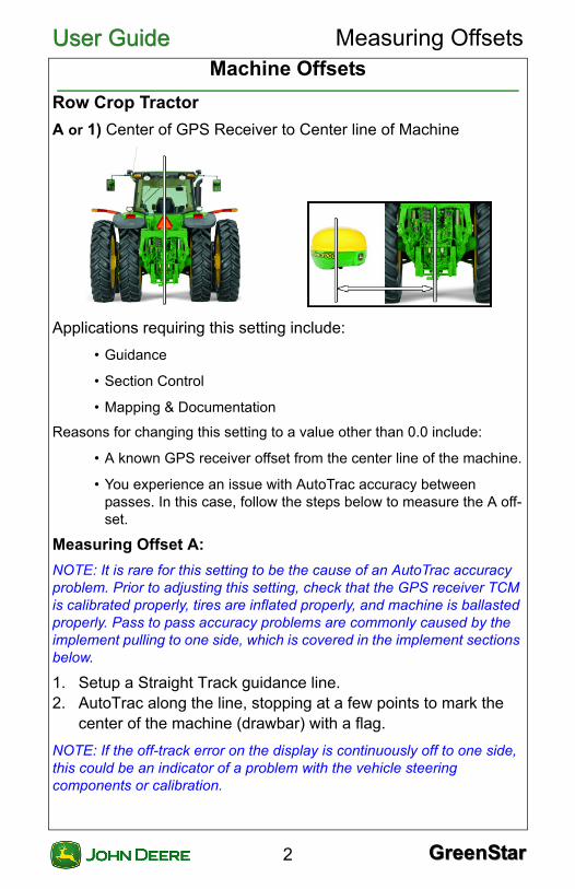
Machine OffsetsRow Crop Tractor
A or 1) Center of GPS Receiver to Center line of Machine
Applications requiring this setting include:
• Guidance
• Section Control
• Mapping & Documentation
Reasons for changing this setting to a value other than 0.0 include:
• A known GPS receiver offset from the center line of the machine.
• You experience an issue with AutoTrac accuracy between passes. In this case, follow the steps below to measure the A off-set.
Measuring Offset A:
NOTE: It is rare for this setting to be the cause of an AutoTrac accuracy problem. Prior to adjusting this setting, check that the GPS receiver TCM is calibrated properly, tires are inflated properly, and machine is ballasted properly. Pass to pass accuracy problems are commonly caused by the implement pulling to one side, which is covered in the implement sections below.
1. Setup a Straight Track guidance line.2. AutoTrac along the line, stopping at a few points to mark the
center of the machine (drawbar) with a flag.
NOTE: If the off-track error on the display is continuously off to one side, this could be an indicator of a problem with the vehicle steering components or calibration.
GreenStarGreenStar2

User GuideUser Guide Measuring Offsets
3. Turn around and AutoTrac back over the same track in theopposite direction, stopping at each flag.4. Measure the distance between the center of the machine and
each flag. If this is a pass to pass issue, there should be a relatively equal amount of difference between the flags throughout the entire pass. If these measurements are within the advertised accuracy of the system (SF1, SF2, RTK) then do not change this offset and check the lateral implement offset instead. Otherwise, divide that measurement in half to determine Offset A.
NOTE: If the tractor needs to drive more to the right of its current path, then toggle the offset direction on the display so that the GPS receiver is shown to the right side of the center-line of the tractor image.
5. Repeat steps 2 through 4 to determine if the offset amount and direction were set properly.
B or 2) Center of GPS Receiver to Center of Non-Steering Axle
Applications requiring this setting include:
• Section Control
GreenStarGreenStar3

User GuideUser Guide Measuring Offsets
• Mapping & DocumentationC or 3) Center of Non-Steering Axle to Connection Point.
Applications requiring this setting include:
• Section Control
• Mapping & Documentation
Measurement point varies by Connection Type:
1. Rear Pivot Drawbar2. Rear Rigid 3-point3. Rear Pivot 2-point4. Rear Pivot Wagon-Hitch [Europe Only]5. Front Rigid 3-point
Connection (or Pivot) Point: The point where the implement connects to the machine or the pivot point between the implement and machine depending on Connection Type. See Machine section above for close up views of the Connection Point.
GreenStarGreenStar4
User GuideUser Guide Measuring Offsets
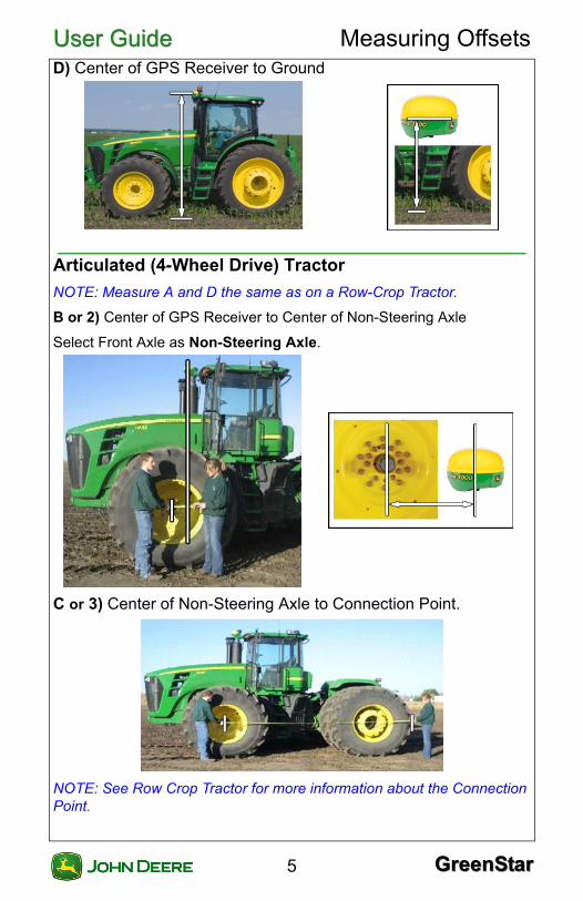
D) Center of GPS Receiver to GroundArticulated (4-Wheel Drive) Tractor
NOTE: Measure A and D the same as on a Row-Crop Tractor.
B or 2) Center of GPS Receiver to Center of Non-Steering Axle
Select Front Axle as Non-Steering Axle.
C or 3) Center of Non-Steering Axle to Connection Point.
NOTE: See Row Crop Tractor for more information about the Connection Point.
GreenStarGreenStar5

User GuideUser Guide Measuring Offsets
Track Tractor
NOTE: Measure A and D the same as on a Row-Crop Tractor.
B or 2) Center of GPS Receiver to Center of Non-Steering Axle.
On the display, select Rear Axle as the non-steering axle. Do not measure to the axle.
Determine the measurement point
1. Apply draft load and ballast that is expected during operation. 2. Make a turn at operating speed. 3. Measure to the point where soil begins to build on outside
track.
GreenStarGreenStar6
User GuideUser Guide Measuring Offsets
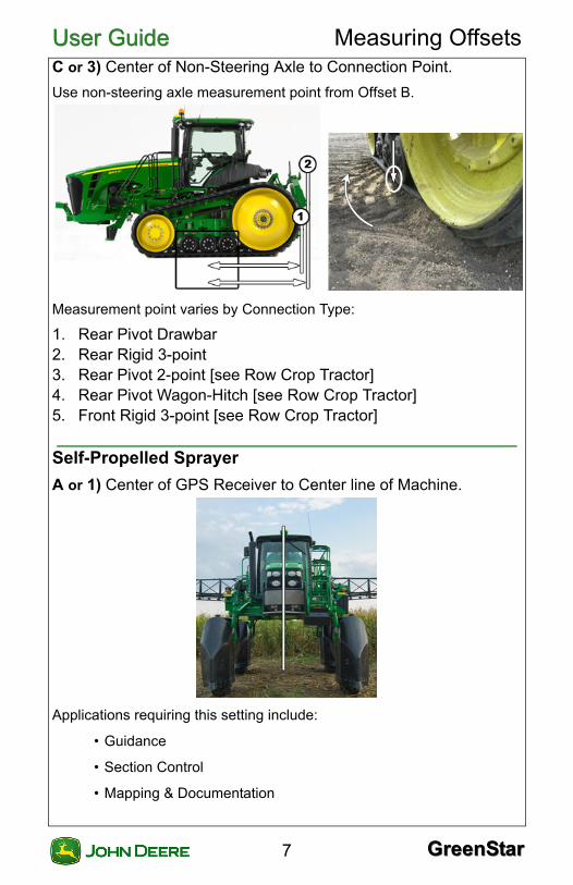
C or 3) Center of Non-Steering Axle to Connection Point.Use non-steering axle measurement point from Offset B.
Measurement point varies by Connection Type:
1. Rear Pivot Drawbar2. Rear Rigid 3-point3. Rear Pivot 2-point [see Row Crop Tractor]4. Rear Pivot Wagon-Hitch [see Row Crop Tractor]5. Front Rigid 3-point [see Row Crop Tractor]
Self-Propelled Sprayer
A or 1) Center of GPS Receiver to Center line of Machine.
Applications requiring this setting include:
• Guidance
• Section Control
• Mapping & Documentation
GreenStarGreenStar7

User GuideUser Guide Measuring Offsets
Reasons for changing this setting to a value other than 0.0 include:• A known GPS receiver offset from the center line of the machine.
• Experience an issue with AutoTrac accuracy between passes. In this case, follow the steps under Row Crop Tractor for measuring Offset A.
B or 2) Center of GPS Receiver to Center of Non-Steering Axle.
C or 3) Center of non-steering axle to spray nozzles (in operating position).
NOTE: This is the point where map recording happens and where sections are turned ON/OFF.
Implement Width: Width of spray area, may extend outside of spray booms.
Harvesters
A or 1) Center of GPS Receiver to Center line of Machine.
Applications requiring this setting include:
• Guidance
GreenStarGreenStar8

User GuideUser Guide Measuring Offsets
• Section Control• Mapping & Documentation
Reasons for changing this setting to a value other than 0.0 include:
• A known GPS receiver offset from the center line of the machine.
• You experience an issue with AutoTrac accuracy between passes. In this case, follow the steps under Row Crop Tractor for measuring Offset A.
B or 2) Center of GPS Receiver to Center of Non-Steering Axle
C or 3) Center of Front Axle to Header Connection Point
GreenStarGreenStar9
User GuideUser Guide Measuring Offsets
Implement OffsetsImplement Offset Descriptions
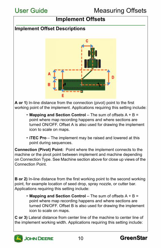
A or 1) In-line distance from the connection (pivot) point to the first working point of the implement. Applications requiring this setting include:
• Mapping and Section Control – The sum of offsets A + B = point where map recording happens and where sections are turned ON/OFF. Offset A is also used for drawing the implement icon to scale on maps.
• iTEC Pro – The implement may be raised and lowered at this point during sequences.
Connection (Pivot) Point: Point where the implement connects to the machine or the pivot point between implement and machine depending on Connection Type. See Machine section above for close up views of the Connection Point.
B or 2) In-line distance from the first working point to the second working point, for example location of seed drop, spray nozzle, or cutter bar. Applications requiring this setting include:
• Mapping and Section Control – The sum of offsets A + B = point where map recording happens and where sections are turned ON/OFF. Offset B is also used for drawing the implement icon to scale on maps.
C or 3) Lateral distance from center line of the machine to center line of the implement working width. Applications requiring this setting include:
GreenStarGreenStar10

User GuideUser Guide Measuring Offsets
• AutoTrac – Guidance lines are centered on the implement.• Mapping and Section Control – The lateral position of the map and sections are determined by offset C.
D or 4) In-line distance from connection (or pivot) point to rotation (control) point of implement. This offset is always 0 for a 3 point hitch implement. Applications requiring this setting include:
• Mapping and Section Control – This offset is important for mod-eling the position of the implement around curves.
Control Point – Rotation Point, point that implement rotates around while in operating position.
E) In-line distance from the connection (or pivot) point to the rear connection point of the first implement. Applications requiring this setting include:
• Mapping and Section Control with Tow-Between Air Carts only.
Implement (Working) Width: The width of the area that is tilled, planted, sprayed, or harvested on each pass through the field. Applications requiring this setting include:
• Mapping and Section Control
• Area Totals
Physical Width: Actual physical width of the implement. Applications requiring this setting include:
• iTEC Pro – This measurement is used for detecting proximity to boundaries.
Harvester Header
NOTE: Offsets A and D are not required for headers and can be set to 0.0.
B or 2) Header Connection Point to Harvesting Point:
• Corn Head: Front of stalk rolls
• Platform Head: Front of cutter bar
• Pickup Head: Front of pickup belt
C or 3) Lateral offset from center of machine to center of the header.
NOTE: C = 0 unless using an offset header.
Implement Width – Width of cut area.
GreenStarGreenStar11
User GuideUser Guide Measuring Offsets
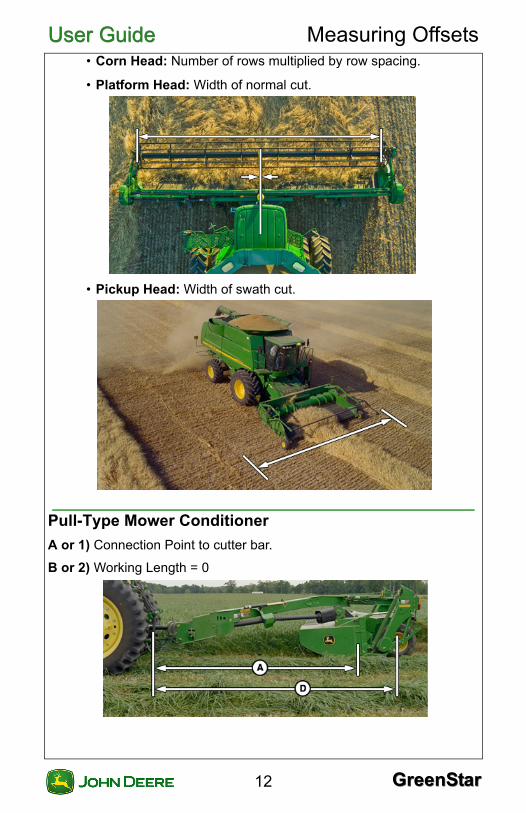
• Corn Head: Number of rows multiplied by row spacing.• Platform Head: Width of normal cut.
• Pickup Head: Width of swath cut.
Pull-Type Mower Conditioner
A or 1) Connection Point to cutter bar.
B or 2) Working Length = 0
GreenStarGreenStar12

User GuideUser Guide Measuring Offsets
C or 3) Lateral offset from center of machine to center of Implement Width.D or 4) Connection Point to rotation point of implement (center of fixed axles).
NOTE: D = 0 for 3-pt mounted implements.
Implement Width: Width of normal cut.
Tri-Fold Mower Conditioner
A or 1) Connection Point to cutter bar.
Mapping point at Rear Implement
Connection Type setting: Rear Rigid 3-point
GreenStarGreenStar13

User GuideUser Guide Measuring Offsets
Mapping point at Front ImplementConnection Type setting: Front Rigid 3-point
B or 2) Working Length = 0.
C or 3) Lateral offset from center of machine to center of Implement Width.
D or 4) D = 0 for 3-pt mounted implements.
Implement Width: Width of normal cut.
One Rear Mower: Lateral Offset Required
GreenStarGreenStar14
User GuideUser Guide Measuring Offsets
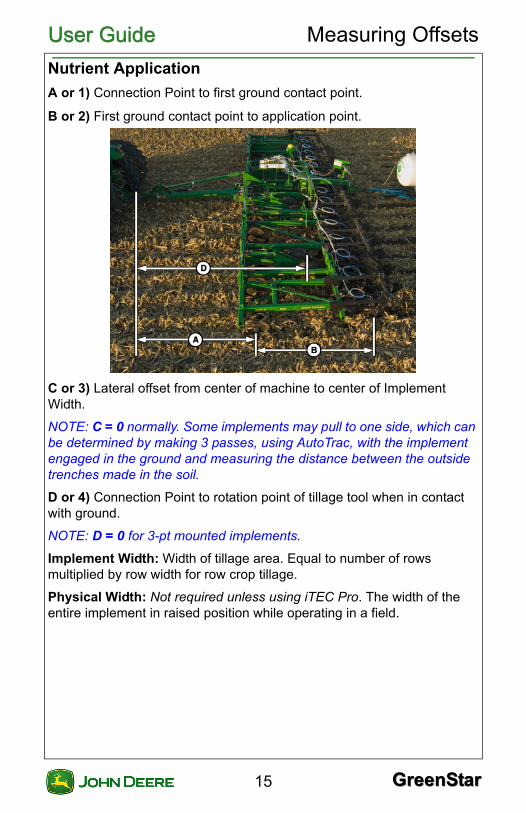
Nutrient Application
A or 1) Connection Point to first ground contact point.
B or 2) First ground contact point to application point.
C or 3) Lateral offset from center of machine to center of Implement Width.
NOTE: C = 0 normally. Some implements may pull to one side, which can be determined by making 3 passes, using AutoTrac, with the implement engaged in the ground and measuring the distance between the outside trenches made in the soil.
D or 4) Connection Point to rotation point of tillage tool when in contact with ground.
NOTE: D = 0 for 3-pt mounted implements.
Implement Width: Width of tillage area. Equal to number of rows multiplied by row width for row crop tillage.
Physical Width: Not required unless using iTEC Pro. The width of the entire implement in raised position while operating in a field.
GreenStarGreenStar15

User GuideUser Guide Measuring Offsets
Planter
A or 1) Connection Point to first ground contact point.
B or 2) First ground contact point to seed drop point.
NOTE: When utilizing a planter with 2 ranks, measure offset B to the midpoint between the ranks. In picture below, only the first rank is being used, so offset B is measured to the first rank.
C or 3) Lateral offset from center of machine to center of Implement Width.
NOTE: C = 0 normally. Some implements may pull to one side, which can be determined by making 3 passes, using AutoTrac, with the implement engaged in the ground and measuring the distance between the outside trenches made in the soil.
D or 4) Connection Point to rotation point of planter (center of fixed axles).
NOTE: D = 0 for 3-pt mounted implements.
Implement Width: Number of rows multiplied by row spacing.
Physical Width: Not required unless using iTEC Pro. The width of the entire implement in raised position while operating in a field, measured to the outside of the planter markers when raised.
GreenStarGreenStar16

User GuideUser Guide Measuring Offsets
Seeder
A or 1) Connection Point to first ground contact point.
B or 2) First ground contact point to seed drop point.
NOTE: When utilizing a seeding tool with multiple ranks, measure offset B to the midpoint between the ranks.
C or 3) Lateral offset from center of machine to center of Implement Width.
NOTE: C = 0 normally. Some implements may pull to one side, which can be determined by making 3 passes, using AutoTrac, with the implement engaged in the ground and measuring the distance between the outside trenches made in the soil.
D or 4) Connection Point to rotation point of seeding tool (center of fixed axles).
NOTE: Caster wheels should not be accounted for in this measurement.
Implement Width: Width of area being seeded.
Physical Width: Not required unless using iTEC Pro. The width of the entire implement in raised position while operating in a field.
GreenStarGreenStar17

User GuideUser Guide Measuring Offsets
Pull-Type Spreader
A or 1) Connection Point to center of spread area.
B or 2) Working Length = 0
C or 3) Lateral offset from center of machine to center of Implement Width. Normally = 0 for spreaders.
D or 4) Connection Point to rotation point of spreader (center of fixed axles).
NOTE: D = 0 for 3-pt mounted implements.
Implement Width: Width of spread area.
Physical Width: Not required unless using iTEC Pro. The width of the physical spreader box.
Pull-Type Sprayer
A or 1) Connection Point to center of spray nozzles.
B or 2) Working Length = 0
GreenStarGreenStar18
User GuideUser Guide Measuring Offsets
C or 3) Lateral offset from center of machine to center of Implement Width. Normally = 0 for sprayers.D or 4) Connection Point to rotation point of sprayer (center of fixed axles).
NOTE: D = 0 for 3-pt mounted implements.
Implement Width: Width of spray area, may extend outside of the spray boom.
Physical Width: Not required unless using iTEC Pro. The width of the spray boom.
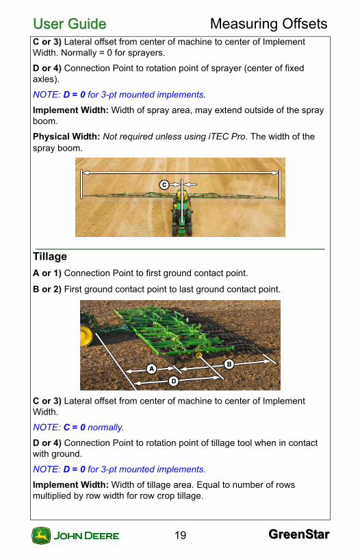
Tillage
A or 1) Connection Point to first ground contact point.
B or 2) First ground contact point to last ground contact point.
C or 3) Lateral offset from center of machine to center of Implement Width.
NOTE: C = 0 normally.
D or 4) Connection Point to rotation point of tillage tool when in contact with ground.
NOTE: D = 0 for 3-pt mounted implements.
Implement Width: Width of tillage area. Equal to number of rows multiplied by row width for row crop tillage.
GreenStarGreenStar19

User GuideUser Guide Measuring Offsets
Physical Width: Not required unless using iTEC Pro. The width of the entire implement in raised position while operating in a field.GreenStarGreenStar20