Embed Size (px)
Citation preview
Technical and Specification Information Greenstar CDi Classic Series
Greenstar Si Series
Greenstar i Junior Series
Greenstar combi gas-fired wall mounted condensing boiler range
NEW Greenstar
CDi Classic
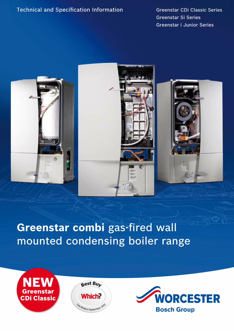
Worcester and you. Making a difference.
As part of the Bosch Group, Worcester
products are designed and manufactured to
provide customers with the highest levels of
quality and reliability which are synonymous
with the Bosch name throughout the world.
As part of Europe’s largest supplier of
heating products, Worcester, Bosch Group
has the UK-based resources and support
capability to offer you the value-added
solutions you deserve. Worcester employs
a nationwide network of Service Engineers
and technically trained Field Sales Managers
supported by an experienced technical
services team which is able to provide
comprehensive support and advice
from design system layouts through
to installation.
Worcester is dedicated to providing energy
efficient gas- and oil-fired condensing
boilers, as well as an extensive range of
renewable technologies. All of our products
have been developed and introduced with
the aim of helping the UK to achieve the
Government’s efficiency targets.
“At Worcester we recognise the vital role
you play in the specification and installation
of ‘A’ rated, energy efficient appliances in
homes across the UK. We will continue to
invest in our products, people, facilities and
added value services to ensure you have all
you require in order to deliver only the best
solutions to your customers’ requirements.”
Carl Arntzen,
Managing Director,
Bosch Thermotechnology UK Ltd.
32
Contents Page
The Greenstar combi condensing boiler range 4 - 5
The features of the Greenstar condensing combi boiler range 6 - 7
Inside story – Greenstar CDi Classic 8
Greenstar CDi Classic technical data 9
Inside story – Greenstar Si and i Junior 10
Greenstar Si and i Junior technical data 11
Optional plug-in controls 12 - 13
Guidance on installing the Greenstar combi range 14 - 21
Horizontal and vertical flue terminal positioning 22 - 23
Greenstar combi boiler range horizontal fluing options 24 - 27
Greenstar combi boiler range vertical fluing options 28 - 30
Plume management system options 31 - 34
Greenfloor Heating 35
Installation requirements 36 - 38
Greenstar combi boiler range accessories 39 - 42
Worcester training 43 - 45
After-sales 46
The reception and main entrance at our Worcester headquarters
54
The Greenstar combi gas-fired wall mounted condensing boiler range
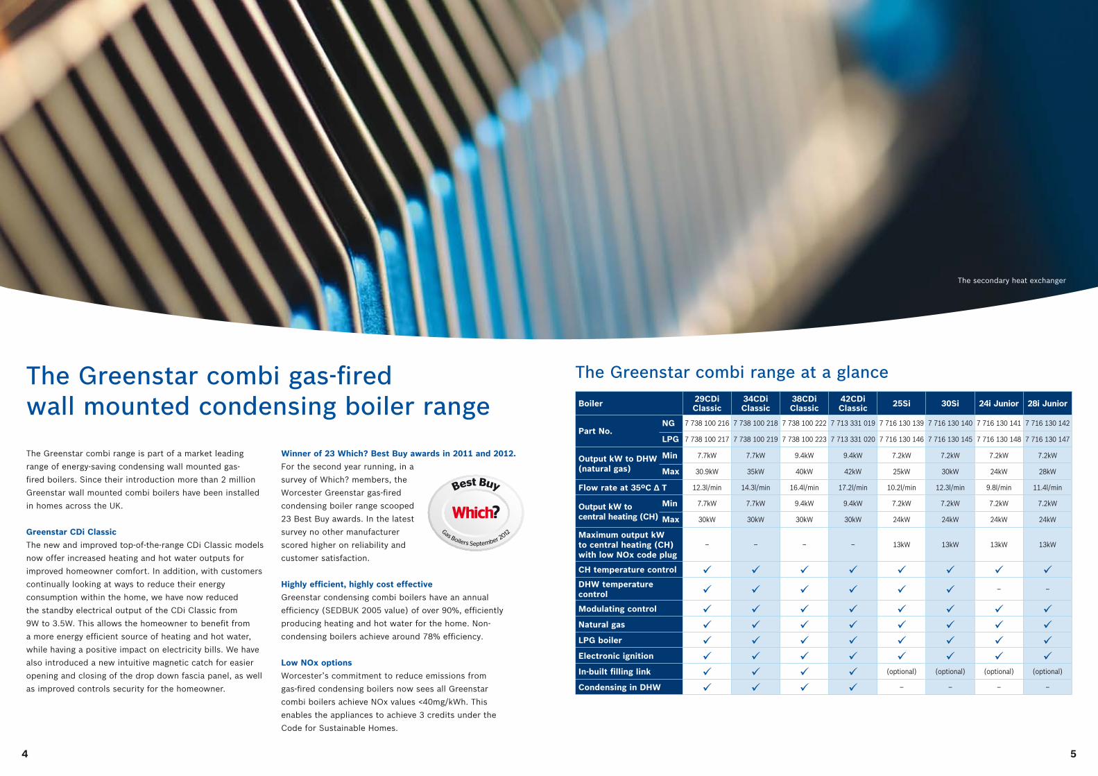
The Greenstar combi range is part of a market leading
range of energy-saving condensing wall mounted gas-
fired boilers. Since their introduction more than 2 million
Greenstar wall mounted combi boilers have been installed
in homes across the UK.
Greenstar CDi Classic
The new and improved top-of-the-range CDi Classic models
now offer increased heating and hot water outputs for
improved homeowner comfort. In addition, with customers
continually looking at ways to reduce their energy
consumption within the home, we have now reduced
the standby electrical output of the CDi Classic from
9W to 3.5W. This allows the homeowner to benefit from
a more energy efficient source of heating and hot water,
while having a positive impact on electricity bills. We have
also introduced a new intuitive magnetic catch for easier
opening and closing of the drop down fascia panel, as well
as improved controls security for the homeowner.
Winner of 23 Which? Best Buy awards in 2011 and 2012.
For the second year running, in a
survey of Which? members, the
Worcester Greenstar gas-fired
condensing boiler range scooped
23 Best Buy awards. In the latest
survey no other manufacturer
scored higher on reliability and
customer satisfaction.
Highly efficient, highly cost effective
Greenstar condensing combi boilers have an annual
efficiency (SEDBUK 2005 value) of over 90%, efficiently
producing heating and hot water for the home. Non-
condensing boilers achieve around 78% efficiency.
Low NOx options
Worcester’s commitment to reduce emissions from
gas-fired condensing boilers now sees all Greenstar
combi boilers achieve NOx values <40mg/kWh. This
enables the appliances to achieve 3 credits under the
Code for Sustainable Homes.
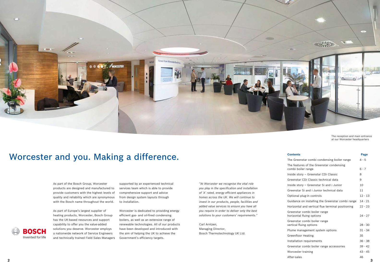
The Greenstar combi range at a glance
Boiler 29CDi Classic
34CDi Classic
38CDi Classic
42CDi Classic 25Si 30Si 24i Junior 28i Junior
Part No. NG
LPG
7 738 100 216 7 738 100 218 7 738 100 222 7 713 331 019 7 716 130 139 7 716 130 140 7 716 130 141 7 716 130 142
7 738 100 217 7 738 100 219 7 738 100 223 7 713 331 020 7 716 130 146 7 716 130 145 7 716 130 148 7 716 130 147
Output kW to DHW Min
(natural gas) Max
7.7kW 7.7kW 9.4kW 9.4kW 7.2kW 7.2kW 7.2kW 7.2kW
30.9kW 35kW 40kW 42kW 25kW 30kW 24kW 28kW
Flow rate at 35ºC ∆ T 12.3l/min 14.3l/min 16.4l/min 17.2l/min 10.2l/min 12.3l/min 9.8l/min 11.4l/min
Output kW to Min
central heating (CH) Max
7.7kW 7.7kW 9.4kW 9.4kW 7.2kW 7.2kW 7.2kW 7.2kW
30kW 30kW 30kW 30kW 24kW 24kW 24kW 24kW
Maximum output kW to central heating (CH) with low NOx code plug
– – – – 13kW 13kW 13kW 13kW
CH temperature control DHW temperature control – –
Modulating control Natural gas LPG boiler Electronic ignition In-built filling link (optional) (optional) (optional) (optional)
Condensing in DHW – – – –
The secondary heat exchanger
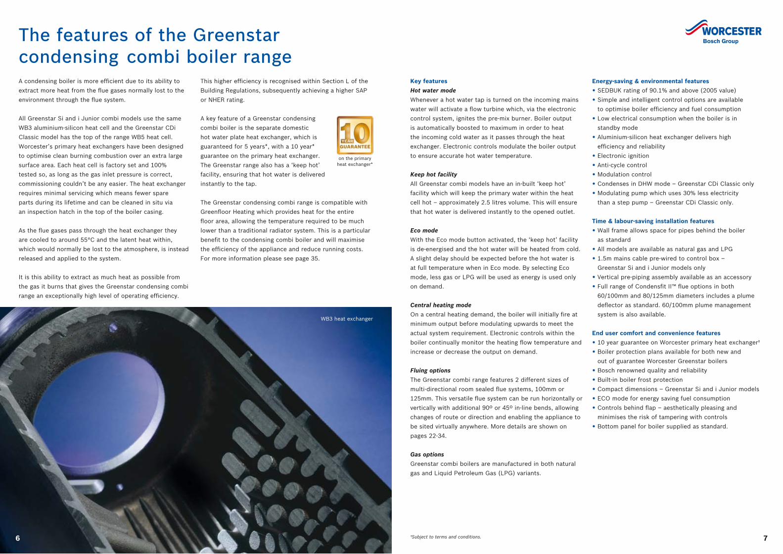
WB3 heat exchanger
76
The features of the Greenstar condensing combi boiler rangeA condensing boiler is more efficient due to its ability to
extract more heat from the flue gases normally lost to the
environment through the flue system.
All Greenstar Si and i Junior combi models use the same
WB3 aluminium-silicon heat cell and the Greenstar CDi
Classic model has the top of the range WB5 heat cell.
Worcester’s primary heat exchangers have been designed
to optimise clean burning combustion over an extra large
surface area. Each heat cell is factory set and 100%
tested so, as long as the gas inlet pressure is correct,
commissioning couldn’t be any easier. The heat exchanger
requires minimal servicing which means fewer spare
parts during its lifetime and can be cleaned in situ via
an inspection hatch in the top of the boiler casing.
As the flue gases pass through the heat exchanger they
are cooled to around 55°C and the latent heat within,
which would normally be lost to the atmosphere, is instead
released and applied to the system.
It is this ability to extract as much heat as possible from
the gas it burns that gives the Greenstar condensing combi
range an exceptionally high level of operating efficiency.
This higher efficiency is recognised within Section L of the
Building Regulations, subsequently achieving a higher SAP
or NHER rating.
A key feature of a Greenstar condensing
combi boiler is the separate domestic
hot water plate heat exchanger, which is
guaranteed for 5 years*, with a 10 year*
guarantee on the primary heat exchanger.
The Greenstar range also has a ‘keep hot’
facility, ensuring that hot water is delivered
instantly to the tap.
The Greenstar condensing combi range is compatible with
Greenfloor Heating which provides heat for the entire
floor area, allowing the temperature required to be much
lower than a traditional radiator system. This is a particular
benefit to the condensing combi boiler and will maximise
the efficiency of the appliance and reduce running costs.
For more information please see page 35.
Energy-saving & environmental features
• SEDBUK rating of 90.1% and above (2005 value)
• Simple and intelligent control options are available
to optimise boiler efficiency and fuel consumption
• Low electrical consumption when the boiler is in
standby mode
• Aluminium-silicon heat exchanger delivers high
efficiency and reliability
• Electronic ignition
• Anti-cycle control
• Modulation control
• Condenses in DHW mode – Greenstar CDi Classic only
• Modulating pump which uses 30% less electricity
than a step pump – Greenstar CDi Classic only.
Time & labour-saving installation features
• Wall frame allows space for pipes behind the boiler
as standard
• All models are available as natural gas and LPG
• 1.5m mains cable pre-wired to control box –
Greenstar Si and i Junior models only
• Vertical pre-piping assembly available as an accessory
• Full range of Condensfit II™ flue options in both
60/100mm and 80/125mm diameters includes a plume
deflector as standard. 60/100mm plume management
system is also available.
End user comfort and convenience features
• 10 year guarantee on Worcester primary heat exchanger†
• Boiler protection plans available for both new and
out of guarantee Worcester Greenstar boilers
• Bosch renowned quality and reliability
• Built-in boiler frost protection
• Compact dimensions – Greenstar Si and i Junior models
• ECO mode for energy saving fuel consumption
• Controls behind flap – aesthetically pleasing and
minimises the risk of tampering with controls
• Bottom panel for boiler supplied as standard.
Key features
Hot water mode
Whenever a hot water tap is turned on the incoming mains
water will activate a flow turbine which, via the electronic
control system, ignites the pre-mix burner. Boiler output
is automatically boosted to maximum in order to heat
the incoming cold water as it passes through the heat
exchanger. Electronic controls modulate the boiler output
to ensure accurate hot water temperature.
Keep hot facility
All Greenstar combi models have an in-built ‘keep hot’
facility which will keep the primary water within the heat
cell hot – approximately 2.5 litres volume. This will ensure
that hot water is delivered instantly to the opened outlet.
Eco mode
With the Eco mode button activated, the ‘keep hot’ facility
is de-energised and the hot water will be heated from cold.
A slight delay should be expected before the hot water is
at full temperature when in Eco mode. By selecting Eco
mode, less gas or LPG will be used as energy is used only
on demand.
Central heating mode
On a central heating demand, the boiler will initially fire at
minimum output before modulating upwards to meet the
actual system requirement. Electronic controls within the
boiler continually monitor the heating flow temperature and
increase or decrease the output on demand.
Fluing options
The Greenstar combi range features 2 different sizes of
multi-directional room sealed flue systems, 100mm or
125mm. This versatile flue system can be run horizontally or
vertically with additional 90º or 45º in-line bends, allowing
changes of route or direction and enabling the appliance to
be sited virtually anywhere. More details are shown on
pages 22-34.
Gas options
Greenstar combi boilers are manufactured in both natural
gas and Liquid Petroleum Gas (LPG) variants.
†Subject to terms and conditions.
on the primary heat exchanger*
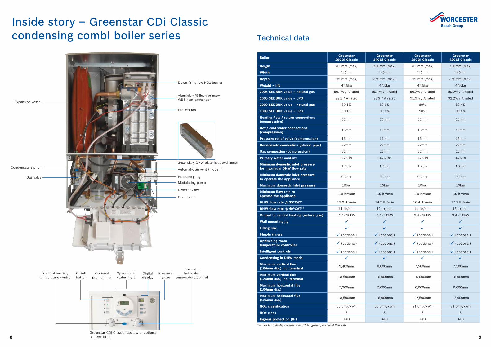
Inside story – Greenstar CDi Classic condensing combi boiler series
98
Technical data
BoilerGreenstar
29CDi ClassicGreenstar
34CDi ClassicGreenstar
38CDi ClassicGreenstar
42CDi Classic
Height 760mm (max) 760mm (max) 760mm (max) 760mm (max)
Width 440mm 440mm 440mm 440mm
Depth 360mm (max) 360mm (max) 360mm (max) 360mm (max)
Weight – lift 47.5kg 47.5kg 47.5kg 47.5kg
2005 SEDBUK value – natural gas 90.1% / A rated 90.1% / A rated 90.2% / A rated 90.2% / A rated
2005 SEDBUK value – LPG 92% / A rated 92% / A rated 91.9% / A rated 92.2% / A rated
2009 SEDBUK value – natural gas 89.1% 89.1% 89% 89.4%
2009 SEDBUK value – LPG 90.1% 90.1% 90% 90.4%
Heating flow / return connections (compression)
22mm 22mm 22mm 22mm
Hot / cold water connections (compression)
15mm 15mm 15mm 15mm
Pressure relief valve (compression) 15mm 15mm 15mm 15mm
Condensate connection (platisc pipe) 22mm 22mm 22mm 22mm
Gas connection (compression) 22mm 22mm 22mm 22mm
Primary water content 3.75 ltr 3.75 ltr 3.75 ltr 3.75 ltr
Minimum domestic inlet pressure for maximum DHW flow rate
1.4bar 1.5bar 1.7bar 1.9bar
Minimum domestic inlet pressure to operate the appliance
0.2bar 0.2bar 0.2bar 0.2bar
Maximum domestic inlet pressure 10bar 10bar 10bar 10bar
Minimum flow rate to operate the appliance
1.9 ltr/min 1.9 ltr/min 1.9 ltr/min 1.9 ltr/min
DHW flow rate @ 35ºC∆T* 12.3 ltr/min 14.3 ltr/min 16.4 ltr/min 17.2 ltr/min
DHW flow rate @ 40ºC∆T** 11 ltr/min 12 ltr/min 14 ltr/min 15 ltr/min
Output to central heating (natural gas) 7.7 - 30kW 7.7 - 30kW 9.4 - 30kW 9.4 - 30kW
Wall mounting jig Filling link Plug-in timers (optional) (optional) (optional) (optional)
Optimising room temperature controller (optional) (optional) (optional) (optional)
Intelligent controls (optional) (optional) (optional) (optional)
Condensing in DHW mode Maximum vertical flue (100mm dia.) inc. terminal
9,400mm 8,000mm 7,500mm 7,500mm
Maximum vertical flue (125mm dia.) inc. terminal
18,500mm 16,000mm 16,000mm 16,000mm
Maximum horizontal flue (100mm dia.)
7,900mm 7,000mm 6,000mm 6,000mm
Maximum horizontal flue (125mm dia.)
18,500mm 16,000mm 12,500mm 12,000mm
NOx classification 33.3mg/kWh 33.3mg/kWh 21.8mg/kWh 21.8mg/kWh
NOx class 5 5 5 5
Ingress protection (IP) X4D X4D X4D X4D
Down firing low NOx burner
Pre-mix fan
Automatic air vent (hidden)
Pressure gauge
Modulating pump
Diverter valve
Drain point
Expansion vessel
Gas valve
Condensate siphon
Aluminium/Silicon primary WB5 heat exchanger
Secondary DHW plate heat exchanger
Central heating temperature control
On/off button
Optional programmer
Operational status light
Digital display
Domestic hot water
temperature controlPressure
gauge
Greenstar CDi Classic fascia with optional DT10RF fitted
*Values for industry comparisons. **Designed operational flow rate.
1110
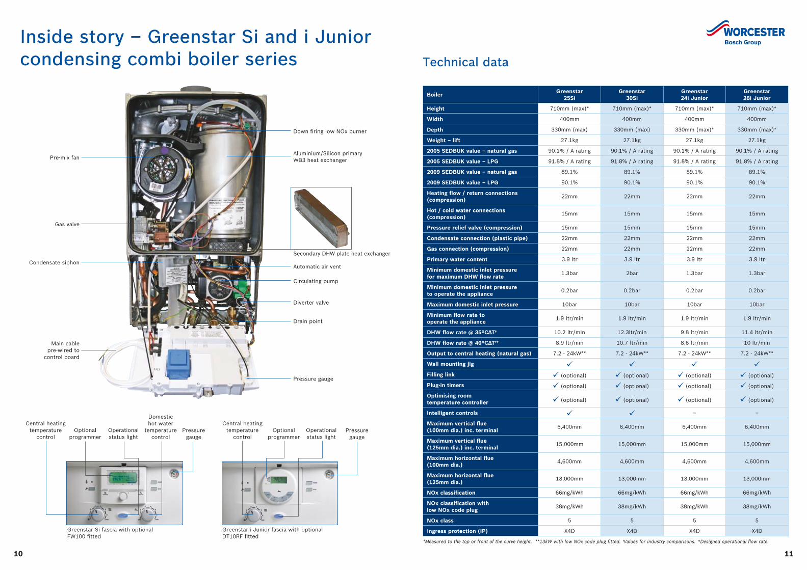
Inside story – Greenstar Si and i Junior condensing combi boiler series Technical data
Pre-mix fan
Gas valve
Condensate siphon
Main cable pre-wired to
control board
Secondary DHW plate heat exchanger
Down firing low NOx burner
Greenstar Si fascia with optional FW100 fitted
Greenstar i Junior fascia with optional DT10RF fitted
Aluminium/Silicon primary WB3 heat exchanger
Automatic air vent
Circulating pump
Diverter valve
Pressure gauge
Drain point
Central heating temperature
control
BoilerGreenstar
25SiGreenstar
30SiGreenstar 24i Junior
Greenstar 28i Junior
Height 710mm (max)* 710mm (max)* 710mm (max)* 710mm (max)*
Width 400mm 400mm 400mm 400mm
Depth 330mm (max) 330mm (max) 330mm (max)* 330mm (max)*
Weight – lift 27.1kg 27.1kg 27.1kg 27.1kg
2005 SEDBUK value – natural gas 90.1% / A rating 90.1% / A rating 90.1% / A rating 90.1% / A rating
2005 SEDBUK value – LPG 91.8% / A rating 91.8% / A rating 91.8% / A rating 91.8% / A rating
2009 SEDBUK value – natural gas 89.1% 89.1% 89.1% 89.1%
2009 SEDBUK value – LPG 90.1% 90.1% 90.1% 90.1%
Heating flow / return connections (compression)
22mm 22mm 22mm 22mm
Hot / cold water connections (compression)
15mm 15mm 15mm 15mm
Pressure relief valve (compression) 15mm 15mm 15mm 15mm
Condensate connection (plastic pipe) 22mm 22mm 22mm 22mm
Gas connection (compression) 22mm 22mm 22mm 22mm
Primary water content 3.9 ltr 3.9 ltr 3.9 ltr 3.9 ltr
Minimum domestic inlet pressure for maximum DHW flow rate
1.3bar 2bar 1.3bar 1.3bar
Minimum domestic inlet pressure to operate the appliance
0.2bar 0.2bar 0.2bar 0.2bar
Maximum domestic inlet pressure 10bar 10bar 10bar 10bar
Minimum flow rate to operate the appliance
1.9 ltr/min 1.9 ltr/min 1.9 ltr/min 1.9 ltr/min
DHW flow rate @ 35ºC∆T† 10.2 ltr/min 12.3ltr/min 9.8 ltr/min 11.4 ltr/min
DHW flow rate @ 40ºC∆T†† 8.9 ltr/min 10.7 ltr/min 8.6 ltr/min 10 ltr/min
Output to central heating (natural gas) 7.2 - 24kW** 7.2 - 24kW** 7.2 - 24kW** 7.2 - 24kW**
Wall mounting jig Filling link (optional) (optional) (optional) (optional)
Plug-in timers (optional) (optional) (optional) (optional)
Optimising room temperature controller (optional) (optional) (optional) (optional)
Intelligent controls – –
Maximum vertical flue (100mm dia.) inc. terminal
6,400mm 6,400mm 6,400mm 6,400mm
Maximum vertical flue (125mm dia.) inc. terminal
15,000mm 15,000mm 15,000mm 15,000mm
Maximum horizontal flue (100mm dia.)
4,600mm 4,600mm 4,600mm 4,600mm
Maximum horizontal flue (125mm dia.)
13,000mm 13,000mm 13,000mm 13,000mm
NOx classification 66mg/kWh 66mg/kWh 66mg/kWh 66mg/kWh
NOx classification with low NOx code plug
38mg/kWh 38mg/kWh 38mg/kWh 38mg/kWh
NOx class 5 5 5 5
Ingress protection (IP) X4D X4D X4D X4D
*Measured to the top or front of the curve height. **13kW with low NOx code plug fitted. †Values for industry comparisons. ††Designed operational flow rate.
Domestic hot water
temperature control
Optional programmer
Operational status light
Pressure gauge
Pressure gauge
Central heating temperature
controlOptional
programmerOperational status light
1312
Increased SAP ratings
As well as all Greenstar combi models achieving very high SAP ratings for dwellings, the addition of an intelligent flow
temperature ‘compensating’ controller can further increase these ratings, as well as being part of the recommended best
practice, as covered by the CHeSS design standard. Load or weather compensation offers around 5% energy savings
compared to standard on/off controls.
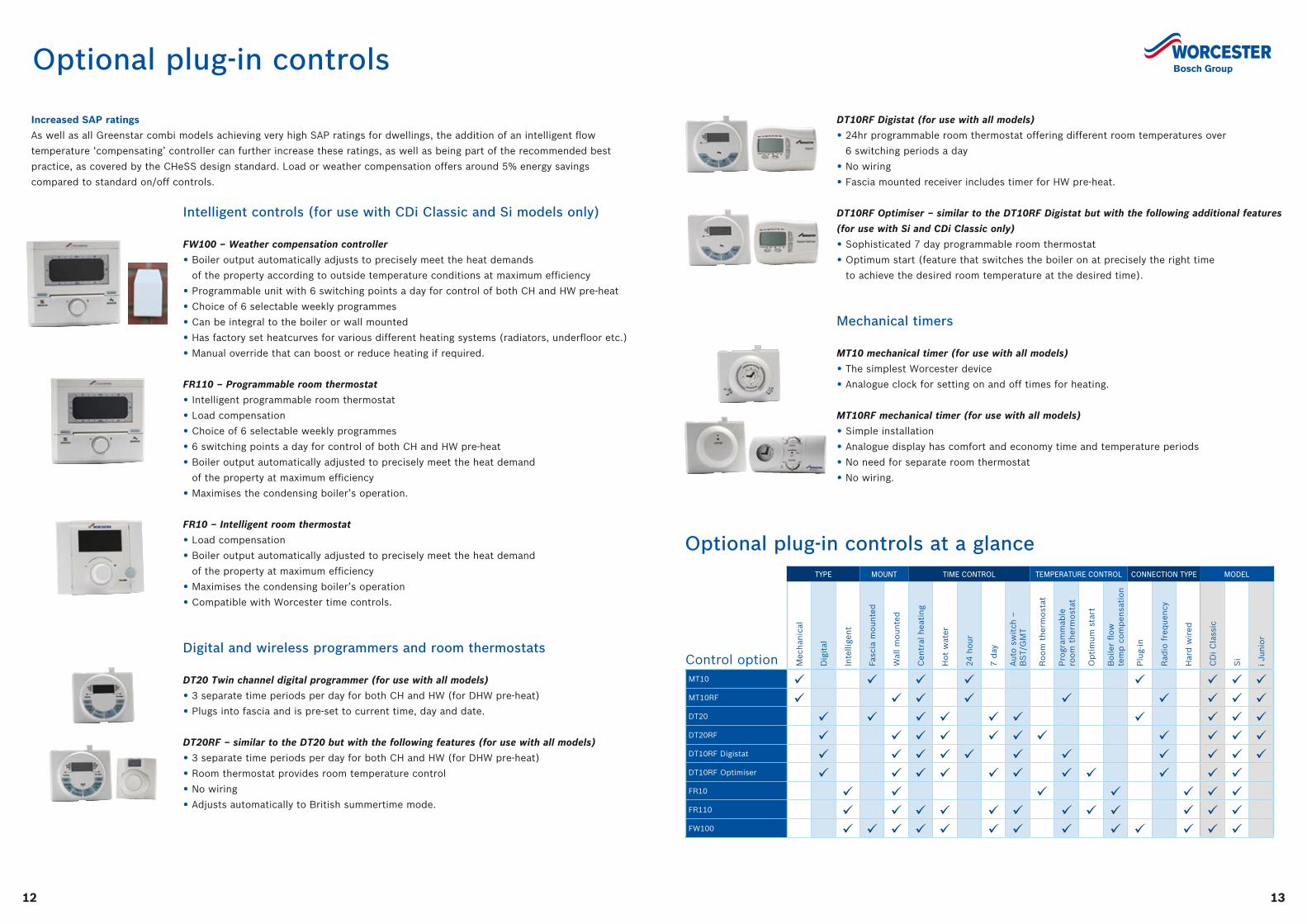
Optional plug-in controls
Intelligent controls (for use with CDi Classic and Si models only)
FW100 – Weather compensation controller
• Boiler output automatically adjusts to precisely meet the heat demands
of the property according to outside temperature conditions at maximum efficiency
• Programmable unit with 6 switching points a day for control of both CH and HW pre-heat
• Choice of 6 selectable weekly programmes
• Can be integral to the boiler or wall mounted
• Has factory set heatcurves for various different heating systems (radiators, underfloor etc.)
• Manual override that can boost or reduce heating if required.
FR110 – Programmable room thermostat
• Intelligent programmable room thermostat
• Load compensation
• Choice of 6 selectable weekly programmes
• 6 switching points a day for control of both CH and HW pre-heat
• Boiler output automatically adjusted to precisely meet the heat demand
of the property at maximum efficiency
• Maximises the condensing boiler’s operation.
FR10 – Intelligent room thermostat
• Load compensation
• Boiler output automatically adjusted to precisely meet the heat demand
of the property at maximum efficiency
• Maximises the condensing boiler’s operation
• Compatible with Worcester time controls.
Digital and wireless programmers and room thermostats
DT20 Twin channel digital programmer (for use with all models)
• 3 separate time periods per day for both CH and HW (for DHW pre-heat)
• Plugs into fascia and is pre-set to current time, day and date.
DT20RF – similar to the DT20 but with the following features (for use with all models)
• 3 separate time periods per day for both CH and HW (for DHW pre-heat)
• Room thermostat provides room temperature control
• No wiring
• Adjusts automatically to British summertime mode.
DT10RF Digistat (for use with all models)
• 24hr programmable room thermostat offering different room temperatures over
6 switching periods a day
• No wiring
• Fascia mounted receiver includes timer for HW pre-heat.
DT10RF Optimiser – similar to the DT10RF Digistat but with the following additional features
(for use with Si and CDi Classic only)
• Sophisticated 7 day programmable room thermostat
• Optimum start (feature that switches the boiler on at precisely the right time
to achieve the desired room temperature at the desired time).
Mechanical timers
MT10 mechanical timer (for use with all models)
• The simplest Worcester device
• Analogue clock for setting on and off times for heating.
MT10RF mechanical timer (for use with all models)
• Simple installation
• Analogue display has comfort and economy time and temperature periods
• No need for separate room thermostat
• No wiring.
TYPE MOUNT TIME CONTROL TEMPERATURE CONTROL CONNECTION TYPE MODEL
Control option Mec
han
ical
Dig
ital
Inte
llige
nt
Fasc
ia m
oun
ted
Wal
l m
oun
ted
Cen
tral
hea
tin
g
Hot
wat
er
24 h
our
7 d
ay
Aut
o s
wit
ch –
B
ST/
GM
T
Ro
om
th
erm
ost
at
Pro
gram
mab
le
roo
m t
her
mo
stat
Op
tim
um s
tart
Bo
iler
flow
te
mp
co
mp
ensa
tio
n
Plu
g-in
Rad
io f
req
uen
cy
Har
d w
ired
CD
i C
lass
ic
Si
i Ju
nio
r
MT10 MT10RF DT20 DT20RF DT10RF Digistat DT10RF Optimiser FR10 FR110 FW100
Optional plug-in controls at a glance
1514
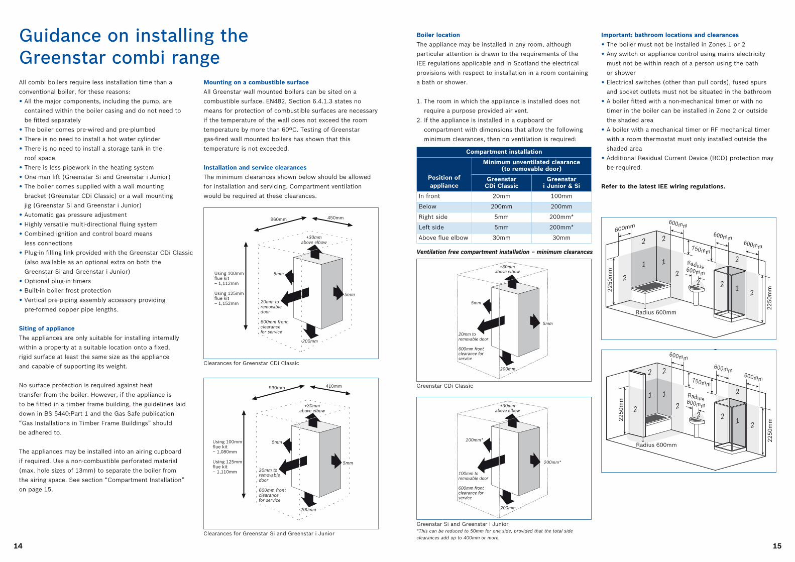
Guidance on installing the Greenstar combi range
Mounting on a combustible surface
All Greenstar wall mounted boilers can be sited on a
combustible surface. EN482, Section 6.4.1.3 states no
means for protection of combustible surfaces are necessary
if the temperature of the wall does not exceed the room
temperature by more than 60ºC. Testing of Greenstar
gas-fired wall mounted boilers has shown that this
temperature is not exceeded.
Installation and service clearances
The minimum clearances shown below should be allowed
for installation and servicing. Compartment ventilation
would be required at these clearances.
960mm 450mm
+30mmabove elbow
5mm
5mm
200mm
20mm to removable door
600mm front clearance for service
Using 100mm flue kit – 1,112mm
Using 125mm flue kit – 1,152mm
Clearances for Greenstar CDi Classic
930mm 410mm
+30mmabove elbow
5mm
5mm
200mm
20mm to removable door
600mm front clearance for service
Using 100mm flue kit – 1,080mm
Using 125mm flue kit – 1,110mm
Clearances for Greenstar Si and Greenstar i Junior
All combi boilers require less installation time than a
conventional boiler, for these reasons:
• All the major components, including the pump, are
contained within the boiler casing and do not need to
be fitted separately
• The boiler comes pre-wired and pre-plumbed
• There is no need to install a hot water cylinder
• There is no need to install a storage tank in the
roof space
• There is less pipework in the heating system
• One-man lift (Greenstar Si and Greenstar i Junior)
• The boiler comes supplied with a wall mounting
bracket (Greenstar CDi Classic) or a wall mounting
jig (Greenstar Si and Greenstar i Junior)
• Automatic gas pressure adjustment
• Highly versatile multi-directional fluing system
• Combined ignition and control board means
less connections
• Plug-in filling link provided with the Greenstar CDi Classic
(also available as an optional extra on both the
Greenstar Si and Greenstar i Junior)
• Optional plug-in timers
• Built-in boiler frost protection
• Vertical pre-piping assembly accessory providing
pre-formed copper pipe lengths.
Siting of appliance
The appliances are only suitable for installing internally
within a property at a suitable location onto a fixed,
rigid surface at least the same size as the appliance
and capable of supporting its weight.
No surface protection is required against heat
transfer from the boiler. However, if the appliance is
to be fitted in a timber frame building, the guidelines laid
down in BS 5440:Part 1 and the Gas Safe publication
“Gas Installations in Timber Frame Buildings” should
be adhered to.
The appliances may be installed into an airing cupboard
if required. Use a non-combustible perforated material
(max. hole sizes of 13mm) to separate the boiler from
the airing space. See section “Compartment Installation”
on page 15.
+30mmabove elbow
200mm*
200mm*
200mm
100mm to removable door
600mm front clearance for service
+30mmabove elbow
5mm
5mm
200mm
20mm to removable door
600mm front clearance for service
Greenstar Si and Greenstar i Junior*This can be reduced to 50mm for one side, provided that the total side clearances add up to 400mm or more.
+30mmabove elbow
200mm*
200mm*
200mm
100mm to removable door
600mm front clearance for service
+30mmabove elbow
5mm
5mm
200mm
20mm to removable door
600mm front clearance for service
Greenstar CDi Classic
Ventilation free compartment installation – minimum clearances
Boiler location
The appliance may be installed in any room, although
particular attention is drawn to the requirements of the
IEE regulations applicable and in Scotland the electrical
provisions with respect to installation in a room containing
a bath or shower.
1. The room in which the appliance is installed does not
require a purpose provided air vent.
2. If the appliance is installed in a cupboard or
compartment with dimensions that allow the following
minimum clearances, then no ventilation is required:
Compartment installation
Position of appliance
Minimum unventilated clearance (to removable door)
Greenstar CDi Classic
Greenstar i Junior & Si
In front 20mm 100mm
Below 200mm 200mm
Right side 5mm 200mm*
Left side 5mm 200mm*
Above flue elbow 30mm 30mm
Important: bathroom locations and clearances
• The boiler must not be installed in Zones 1 or 2
• Any switch or appliance control using mains electricity
must not be within reach of a person using the bath
or shower
• Electrical switches (other than pull cords), fused spurs
and socket outlets must not be situated in the bathroom
• A boiler fitted with a non-mechanical timer or with no
timer in the boiler can be installed in Zone 2 or outside
the shaded area
• A boiler with a mechanical timer or RF mechanical timer
with a room thermostat must only installed outside the
shaded area
• Additional Residual Current Device (RCD) protection may
be required.
Refer to the latest IEE wiring regulations.
Radius 600mm
Radius600mm
2
1
22
2
12
2
600mm
2
1
2
600mm
600mm
600mm750mm
2250m
m
2250m
m
Radius 600mm
Radius600mm
2
1
22
2
12
2
2
1
600mm
600mm
600mm750mm
2250m
m
2250m
m
2
Radius 600mm
Radius600mm
2
1
22
2
12
2
600mm
2
1
2
600mm
600mm
600mm750mm
2250m
m
2250m
m
Radius 600mm
Radius600mm
2
1
22
2
12
2
2
1
600mm
600mm
600mm750mm
2250m
m
2250m
m
2
1716
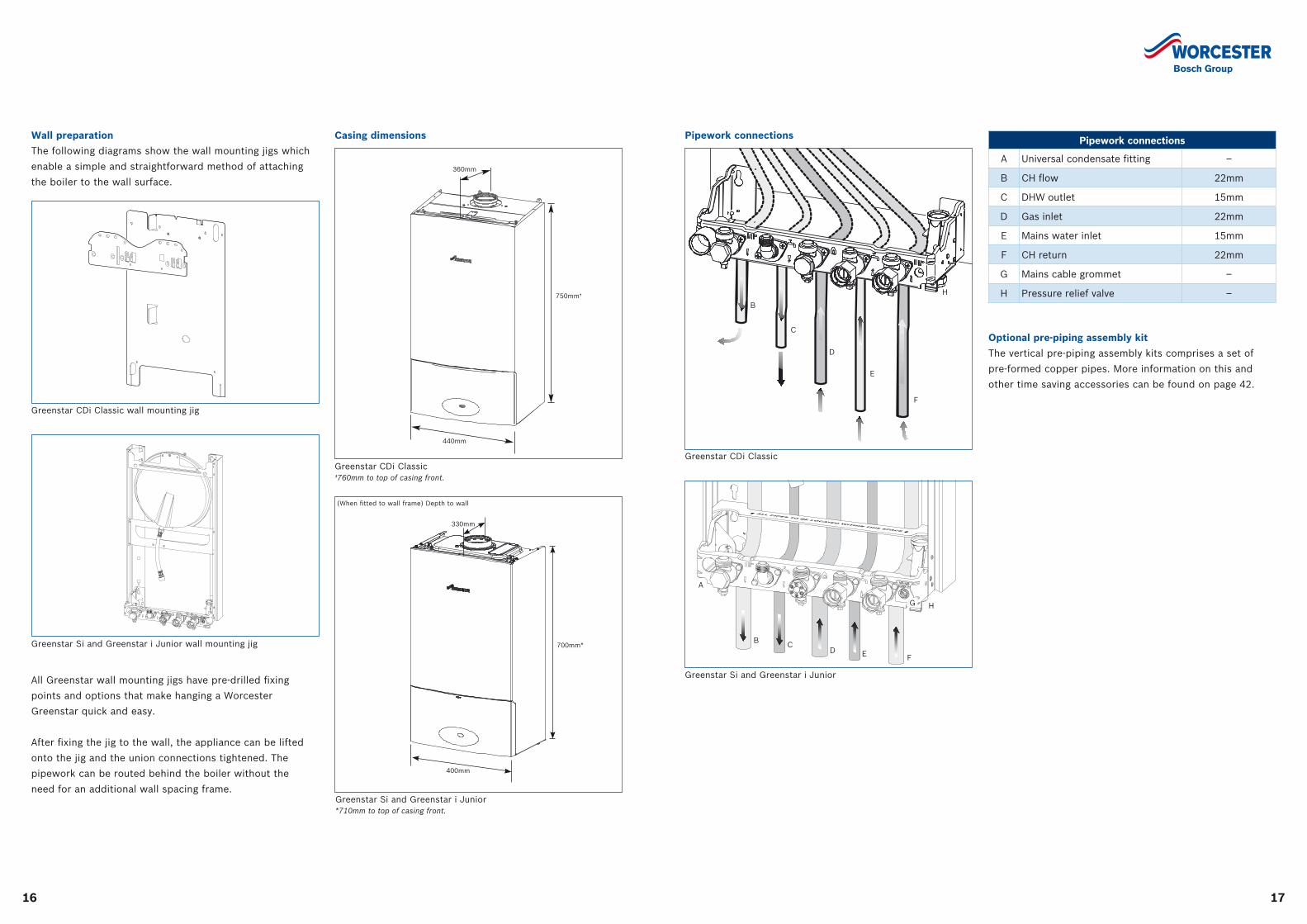
Optional pre-piping assembly kit
The vertical pre-piping assembly kits comprises a set of
pre-formed copper pipes. More information on this and
other time saving accessories can be found on page 42.
330mm
400mm
700mm*
(When fitted to wall frame) Depth to wall
Greenstar Si and Greenstar i Junior*710mm to top of casing front.
Greenstar CDi Classic †760mm to top of casing front.
750mm†
440mm
360mm
Casing dimensions Pipework connections
A Universal condensate fitting –
B CH flow 22mm
C DHW outlet 15mm
D Gas inlet 22mm
E Mains water inlet 15mm
F CH return 22mm
G Mains cable grommet –
H Pressure relief valve –
A
B CD E F
G
Greenstar Si and Greenstar i Junior
H
B
C
D
E
F
H
Greenstar CDi Classic
Pipework connections
All Greenstar wall mounting jigs have pre-drilled fixing
points and options that make hanging a Worcester
Greenstar quick and easy.
After fixing the jig to the wall, the appliance can be lifted
onto the jig and the union connections tightened. The
pipework can be routed behind the boiler without the
need for an additional wall spacing frame.
Greenstar CDi Classic wall mounting jig
Wall preparation
The following diagrams show the wall mounting jigs which
enable a simple and straightforward method of attaching
the boiler to the wall surface.
Greenstar Si and Greenstar i Junior wall mounting jig
1918
Pipe work transition
500mm min.
25mm min.
400mmmin.
Siphon trap
Bottom of sealed tubeLimestone chippings
100mm dia. min. plastic pipe
25mm min.
External rain water pipe into foul water
External air break
Air gap
25mm min.
Insulate & increase pipe size
Condensatepump
External Options
100mm dia.
Siphon trap
Siphon trap
Siphon trap
Pipe work transition
Insulate & increase pipe size
Pipe work transition
Pipe work transition
Insulate & increase pipe size
68mm dia. PVCu strap on fittingCondensate
pump
Insulate & increase pipe size
Drainage holes
100mm dia. min. plastic pipe
25mm25mm
50mm
25mm
300mm
Drainage holes12mm dia.
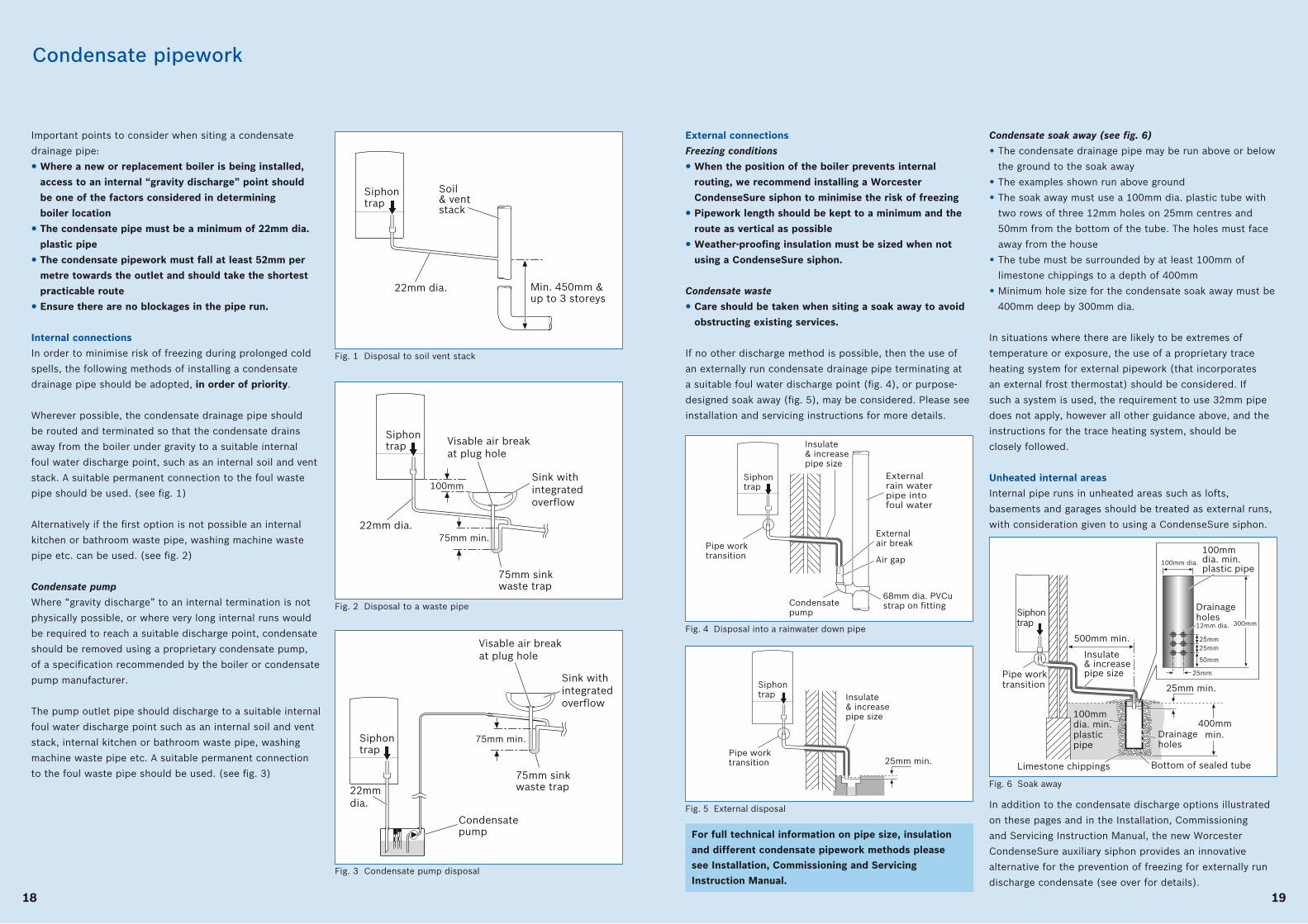
Fig. 4 Disposal into a rainwater down pipe
Pipe work transition
500mm min.
25mm min.
400mmmin.
Siphon trap
Bottom of sealed tubeLimestone chippings
100mm dia. min. plastic pipe
25mm min.
External rain water pipe into foul water
External air break
Air gap
25mm min.
Insulate & increase pipe size
Condensatepump
External Options
100mm dia.
Siphon trap
Siphon trap
Siphon trap
Pipe work transition
Insulate & increase pipe size
Pipe work transition
Pipe work transition
Insulate & increase pipe size
68mm dia. PVCu strap on fittingCondensate
pump
Insulate & increase pipe size
Drainage holes
100mm dia. min. plastic pipe
25mm25mm
50mm
25mm
300mm
Drainage holes12mm dia.
Fig. 5 External disposal
Pipe work transition
500mm min.
25mm min.
400mmmin.
Siphon trap
Bottom of sealed tubeLimestone chippings
100mm dia. min. plastic pipe
25mm min.
External rain water pipe into foul water
External air break
Air gap
25mm min.
Insulate & increase pipe size
Condensatepump
External Options
100mm dia.
Siphon trap
Siphon trap
Siphon trap
Pipe work transition
Insulate & increase pipe size
Pipe work transition
Pipe work transition
Insulate & increase pipe size
68mm dia. PVCu strap on fittingCondensate
pump
Insulate & increase pipe size
Drainage holes
100mm dia. min. plastic pipe
25mm25mm
50mm
25mm
300mm
Drainage holes12mm dia.
Fig. 6 Soak away
For full technical information on pipe size, insulation
and different condensate pipework methods please
see Installation, Commissioning and Servicing
Instruction Manual.
Condensate soak away (see fig. 6)
• The condensate drainage pipe may be run above or below
the ground to the soak away
• The examples shown run above ground
• The soak away must use a 100mm dia. plastic tube with
two rows of three 12mm holes on 25mm centres and
50mm from the bottom of the tube. The holes must face
away from the house
• The tube must be surrounded by at least 100mm of
limestone chippings to a depth of 400mm
• Minimum hole size for the condensate soak away must be
400mm deep by 300mm dia.
In situations where there are likely to be extremes of
temperature or exposure, the use of a proprietary trace
heating system for external pipework (that incorporates
an external frost thermostat) should be considered. If
such a system is used, the requirement to use 32mm pipe
does not apply, however all other guidance above, and the
instructions for the trace heating system, should be
closely followed.
Unheated internal areas
Internal pipe runs in unheated areas such as lofts,
basements and garages should be treated as external runs,
with consideration given to using a CondenseSure siphon.
External connections
Freezing conditions
• When the position of the boiler prevents internal
routing, we recommend installing a Worcester
CondenseSure siphon to minimise the risk of freezing
• Pipework length should be kept to a minimum and the
route as vertical as possible
• Weather-proofing insulation must be sized when not
using a CondenseSure siphon.
Condensate waste
• Care should be taken when siting a soak away to avoid
obstructing existing services.
If no other discharge method is possible, then the use of
an externally run condensate drainage pipe terminating at
a suitable foul water discharge point (fig. 4), or purpose-
designed soak away (fig. 5), may be considered. Please see
installation and servicing instructions for more details.
Important points to consider when siting a condensate
drainage pipe:
• Where a new or replacement boiler is being installed,
access to an internal “gravity discharge” point should
be one of the factors considered in determining
boiler location
• The condensate pipe must be a minimum of 22mm dia.
plastic pipe
• The condensate pipework must fall at least 52mm per
metre towards the outlet and should take the shortest
practicable route
• Ensure there are no blockages in the pipe run.
Internal connections
In order to minimise risk of freezing during prolonged cold
spells, the following methods of installing a condensate
drainage pipe should be adopted, in order of priority.
Wherever possible, the condensate drainage pipe should
be routed and terminated so that the condensate drains
away from the boiler under gravity to a suitable internal
foul water discharge point, such as an internal soil and vent
stack. A suitable permanent connection to the foul waste
pipe should be used. (see fig. 1)
Alternatively if the first option is not possible an internal
kitchen or bathroom waste pipe, washing machine waste
pipe etc. can be used. (see fig. 2)
Condensate pump
Where “gravity discharge” to an internal termination is not
physically possible, or where very long internal runs would
be required to reach a suitable discharge point, condensate
should be removed using a proprietary condensate pump,
of a specification recommended by the boiler or condensate
pump manufacturer.
The pump outlet pipe should discharge to a suitable internal
foul water discharge point such as an internal soil and vent
stack, internal kitchen or bathroom waste pipe, washing
machine waste pipe etc. A suitable permanent connection
to the foul waste pipe should be used. (see fig. 3)
Condensate pipework
100mm
75mm min.
Visable air break at plug hole
Sink with integrated overflow
75mm sink waste trap
Condensate pump
Soil & vent stack
22mm dia.
22mm dia.
22mm dia.
Siphon trap
Min. 450mm & up to 3 storeys
Internal Options
75mm min.
Siphon trap
Siphon trap
Visable air break at plug hole
Sink with integrated overflow
75mm sink waste trap
Fig. 1 Disposal to soil vent stack
100mm
75mm min.
Visable air break at plug hole
Sink with integrated overflow
75mm sink waste trap
Condensate pump
Soil & vent stack
22mm dia.
22mm dia.
22mm dia.
Siphon trap
Min. 450mm & up to 3 storeys
Internal Options
75mm min.
Siphon trap
Siphon trap
Visable air break at plug hole
Sink with integrated overflow
75mm sink waste trap
Fig. 2 Disposal to a waste pipe
100mm
75mm min.
Visable air break at plug hole
Sink with integrated overflow
75mm sink waste trap
Condensate pump
Soil & vent stack
22mm dia.
22mm dia.
22mm dia.
Siphon trap
Min. 450mm & up to 3 storeys
Internal Options
75mm min.
Siphon trap
Siphon trap
Visable air break at plug hole
Sink with integrated overflow
75mm sink waste trap
Fig. 3 Condensate pump disposal
In addition to the condensate discharge options illustrated
on these pages and in the Installation, Commissioning
and Servicing Instruction Manual, the new Worcester
CondenseSure auxiliary siphon provides an innovative
alternative for the prevention of freezing for externally run
discharge condensate (see over for details).
2120
With climate change and extreme weather variations
becoming increasingly common, and very cold winters with
temperatures as low as -20°C being experienced, practices
such as externally run condensate discharge pipework are
now being questioned.
The CondenseSure auxiliary siphon has been designed to
allow a more flexible approach to boiler siting.
Tested to extreme temperatures
CondenseSure has been extensively tested under
simulated extreme weather conditions and proved its
effectiveness in preventing frozen condensate at -15ºC
for a sustained period of 48 hours.
CondenseSure principle of operation
Within most condensing boilers there is an internal
siphon which holds around 100ml of condensate before
being released down the condensate discharge pipe. A
typical A-rated condensing boiler will generate up to 2
litres of condensate an hour (dependant on output and
temperature) and this will result in the in-built siphon
discharging approximately every 3 minutes. With this
frequency of discharge it is unlikely that the condensate
pipework is ever empty of condensate, consequently
increasing the potential for freezing of the pipework in
prolonged sub-zero temperatures.
The CondenseSure siphon connects to the boiler
condensate discharge outlet and collects the condensate
into a larger volume before releasing it into the
discharge pipe.
With this expanded siphonic operation, the discharge from
the CondenseSure is every 15 to 20 minutes, resulting in:
• Increased velocity and flow rate
• With only 3 to 4 siphonic actions per hour,
the condensate pipework is empty for longer
• Significantly decreased or even eliminated
freezing potential.
A universal fitting for new and existing installations
Although developed specifically for Worcester Greenstar
gas- and oil-fired boilers, the Worcester CondenseSure
has the added advantage of being able to be fitted to
any make of condensing boiler for both new and retrofit
installations. CondenseSure can provide a simple solution
which eliminates the need for re-siting both the new boiler
and the system pipework when replacing an existing
non-condensing appliance. CondenseSure can easily be
fitted to existing installations to provide peace of mind in
extreme weather conditions.
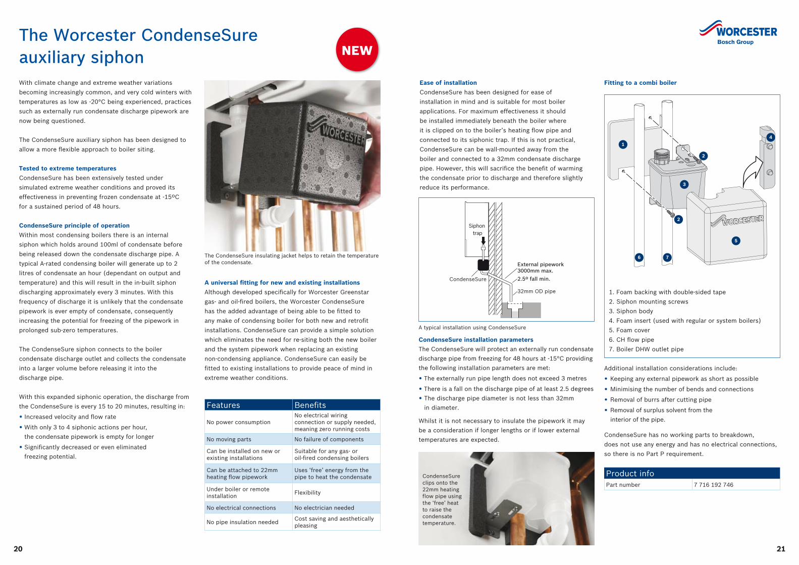
Fitting to a combi boiler
The Worcester CondenseSure auxiliary siphon
Ease of installation
CondenseSure has been designed for ease of
installation in mind and is suitable for most boiler
applications. For maximum effectiveness it should
be installed immediately beneath the boiler where
it is clipped on to the boiler’s heating flow pipe and
connected to its siphonic trap. If this is not practical,
CondenseSure can be wall-mounted away from the
boiler and connected to a 32mm condensate discharge
pipe. However, this will sacrifice the benefit of warming
the condensate prior to discharge and therefore slightly
reduce its performance.
Additional installation considerations include:
• Keeping any external pipework as short as possible
• Minimising the number of bends and connections
• Removal of burrs after cutting pipe
• Removal of surplus solvent from the
interior of the pipe.
CondenseSure has no working parts to breakdown,
does not use any energy and has no electrical connections,
so there is no Part P requirement.
1.
2.
3.7
1
2
3
5
6
4
1. Foam backing with double-sided tape
2. Siphon mounting screws
3. Siphon body
4. Foam insert (used with regular or system boilers)
5. Foam cover
6. CH flow pipe
7. Boiler DHW outlet pipe
1
2
2
3
4
5
6 7
A typical installation using CondenseSure
External pipework3000mm max.
CondenseSure 2.5º fall min.
32mm OD pipe
Siphon trap
NEW
CondenseSure clips onto the 22mm heating flow pipe using the ‘free’ heat to raise the condensate temperature.
The CondenseSure insulating jacket helps to retain the temperature of the condensate.
Features Benefits
No power consumptionNo electrical wiring connection or supply needed, meaning zero running costs
No moving parts No failure of components
Can be installed on new or existing installations
Suitable for any gas- or oil-fired condensing boilers
Can be attached to 22mm heating flow pipework
Uses ‘free’ energy from the pipe to heat the condensate
Under boiler or remote installation
Flexibility
No electrical connections No electrician needed
No pipe insulation neededCost saving and aesthetically pleasing
Product infoPart number 7 716 192 746
CondenseSure installation parameters
The CondenseSure will protect an externally run condensate
discharge pipe from freezing for 48 hours at -15°C providing
the following installation parameters are met:
• The externally run pipe length does not exceed 3 metres
• There is a fall on the discharge pipe of at least 2.5 degrees
• The discharge pipe diameter is not less than 32mm
in diameter.
Whilst it is not necessary to insulate the pipework it may
be a consideration if longer lengths or if lower external
temperatures are expected.
2322
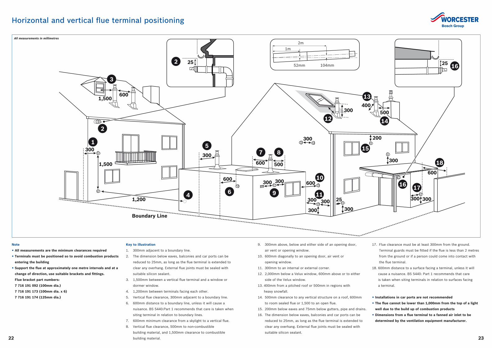
Horizontal and vertical flue terminal positioning
16
600
300
200
300
1,200
Boundary Line
1,500
1,500
2
1
12
11
10
9
5
18
7
6
13
15
4
3
17
14
300 300
300 300
300
300 300
500600
300
600
600
400
30025
8
300
500
600
300
252 25 16
2m
1m
52mm 104mm
Note
• All measurements are the minimum clearances required
• Terminals must be positioned so to avoid combustion products
entering the building
• Support the flue at approximately one metre intervals and at a
change of direction, use suitable brackets and fittings.
Flue bracket part numbers:
7 716 191 092 (100mm dia.)
7 716 191 173 (100mm dia. x 6)
7 716 191 174 (125mm dia.)
9. 300mm above, below and either side of an opening door,
air vent or opening window.
10. 600mm diagonally to an opening door, air vent or
opening window.
11. 300mm to an internal or external corner.
12. 2,000mm below a Velux window, 600mm above or to either
side of the Velux window.
13. 400mm from a pitched roof or 500mm in regions with
heavy snowfall.
14. 500mm clearance to any vertical structure on a roof, 600mm
to room sealed flue or 1,500 to an open flue.
15. 200mm below eaves and 75mm below gutters, pipe and drains.
16. The dimension below eaves, balconies and car ports can be
reduced to 25mm, as long as the flue terminal is extended to
clear any overhang. External flue joints must be sealed with
suitable silicon sealant.
17. Flue clearance must be at least 300mm from the ground.
Terminal guards must be fitted if the flue is less than 2 metres
from the ground or if a person could come into contact with
the flue terminal.
18. 600mm distance to a surface facing a terminal, unless it will
cause a nuisance. BS 5440: Part 1 recommends that care
is taken when siting terminals in relation to surfaces facing
a terminal.
• Installations in car ports are not recommended
• The flue cannot be lower than 1,000mm from the top of a light
well due to the build up of combustion products
• Dimensions from a flue terminal to a fanned air inlet to be
determined by the ventilation equipment manufacturer.
Key to illustration
1. 300mm adjacent to a boundary line.
2. The dimension below eaves, balconies and car ports can be
reduced to 25mm, as long as the flue terminal is extended to
clear any overhang. External flue joints must be sealed with
suitable silicon sealant.
3. 1,500mm between a vertical flue terminal and a window or
dormer window.
4. 1,200mm between terminals facing each other.
5. Vertical flue clearance, 300mm adjacent to a boundary line.
6. 600mm distance to a boundary line, unless it will cause a
nuisance. BS 5440:Part 1 recommends that care is taken when
siting terminal in relation to boundary lines.
7. 600mm minimum clearance from a skylight to a vertical flue.
8. Vertical flue clearance, 500mm to non-combustible
building material, and 1,500mm clearance to combustible
building material.
All measurements in millimetres
2524
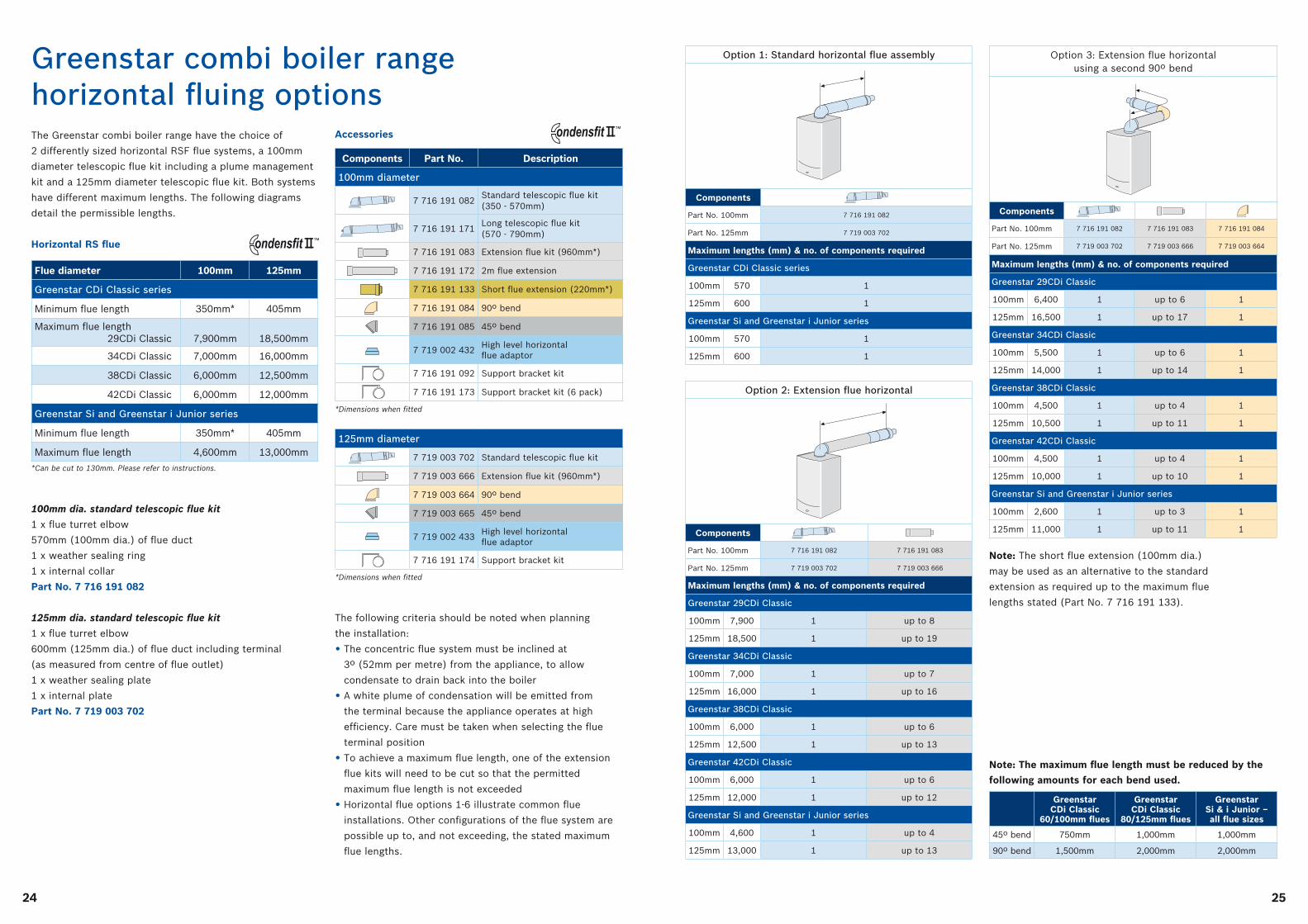
Greenstar combi boiler range horizontal fluing options The Greenstar combi boiler range have the choice of
2 differently sized horizontal RSF flue systems, a 100mm
diameter telescopic flue kit including a plume management
kit and a 125mm diameter telescopic flue kit. Both systems
have different maximum lengths. The following diagrams
detail the permissible lengths.
Horizontal RS flue
The following criteria should be noted when planning
the installation:
• The concentric flue system must be inclined at
3º (52mm per metre) from the appliance, to allow
condensate to drain back into the boiler
• A white plume of condensation will be emitted from
the terminal because the appliance operates at high
efficiency. Care must be taken when selecting the flue
terminal position
• To achieve a maximum flue length, one of the extension
flue kits will need to be cut so that the permitted
maximum flue length is not exceeded
• Horizontal flue options 1-6 illustrate common flue
installations. Other configurations of the flue system are
possible up to, and not exceeding, the stated maximum
flue lengths.
100mm dia. standard telescopic flue kit
1 x flue turret elbow
570mm (100mm dia.) of flue duct
1 x weather sealing ring
1 x internal collar
Part No. 7 716 191 082
125mm dia. standard telescopic flue kit
1 x flue turret elbow
600mm (125mm dia.) of flue duct including terminal
(as measured from centre of flue outlet)
1 x weather sealing plate
1 x internal plate
Part No. 7 719 003 702
Note: The short flue extension (100mm dia.)
may be used as an alternative to the standard
extension as required up to the maximum flue
lengths stated (Part No. 7 716 191 133).
Accessories
Flue diameter 100mm 125mm
Greenstar CDi Classic series
Minimum flue length 350mm* 405mm
Maximum flue length 29CDi Classic
7,900mm
18,500mm
34CDi Classic 7,000mm 16,000mm
38CDi Classic 6,000mm 12,500mm
42CDi Classic 6,000mm 12,000mm
Greenstar Si and Greenstar i Junior series
Minimum flue length 350mm* 405mm
Maximum flue length 4,600mm 13,000mm
*Can be cut to 130mm. Please refer to instructions.
Components Part No. Description
100mm diameter
7 716 191 082Standard telescopic flue kit (350 - 570mm)
7 716 191 171Long telescopic flue kit (570 - 790mm)
7 716 191 083 Extension flue kit (960mm*)
7 716 191 172 2m flue extension
7 716 191 133 Short flue extension (220mm*)
7 716 191 084 90º bend
7 716 191 085 45º bend
7 719 002 432High level horizontal flue adaptor
7 716 191 092 Support bracket kit
7 716 191 173 Support bracket kit (6 pack)
*Dimensions when fitted
125mm diameter
7 719 003 702 Standard telescopic flue kit
7 719 003 666 Extension flue kit (960mm*)
7 719 003 664 90º bend
7 719 003 665 45º bend
7 719 002 433High level horizontal flue adaptor
7 716 191 174 Support bracket kit
*Dimensions when fitted
Min.120mm
Min.120mm
Min.120mm
300mm
500mm
Pitchedroof
Flat roof
Min.120mm
Min.120mm
Min.120mm
Min.120mm
Min.120mm
300mm
500mm
Pitchedroof
Flat roof
Min.120mm
Min.120mm
Min.120mm
Min.120mm
Min.120mm
300mm
500mm
Pitchedroof
Flat roof
Min.120mm
Min.120mm
Min.120mm
Min.120mm
Min.120mm
300mm
500mm
Pitchedroof
Flat roof
Min.120mm
Min.120mm
Min.120mm
Min.120mm
Min.120mm
300mm
500mm
Pitchedroof
Flat roof
Min.120mm
Min.120mm
Min.120mm
Min.120mm
Min.120mm
300mm
500mm
Pitchedroof
Flat roof
Min.120mm
Min.120mm
Min.120mm
Min.120mm
Min.120mm
300mm
500mm
Pitchedroof
Flat roof
Min.120mm
Min.120mm
Min.120mm
Min.120mm
Min.120mm
300mm
500mm
Pitchedroof
Flat roof
Min.120mm
Min.120mm
Min.120mm
Min.120mm
Min.120mm
300mm
500mm
Pitchedroof
Flat roof
Min.120mm
Min.120mm
Option 1: Standard horizontal flue assembly
Components
Part No. 100mm 7 716 191 082
Part No. 125mm 7 719 003 702
Maximum lengths (mm) & no. of components required
Greenstar CDi Classic series
100mm 570 1
125mm 600 1
Greenstar Si and Greenstar i Junior series
100mm 570 1
125mm 600 1
Option 2: Extension flue horizontal
Components
Part No. 100mm 7 716 191 082 7 716 191 083
Part No. 125mm 7 719 003 702 7 719 003 666
Maximum lengths (mm) & no. of components required
Greenstar 29CDi Classic
100mm 7,900 1 up to 8
125mm 18,500 1 up to 19
Greenstar 34CDi Classic
100mm 7,000 1 up to 7
125mm 16,000 1 up to 16
Greenstar 38CDi Classic
100mm 6,000 1 up to 6
125mm 12,500 1 up to 13
Greenstar 42CDi Classic
100mm 6,000 1 up to 6
125mm 12,000 1 up to 12
Greenstar Si and Greenstar i Junior series
100mm 4,600 1 up to 4
125mm 13,000 1 up to 13
Min.120mm
Min.120mm
Min.120mm
300mm
500mm
Pitchedroof
Flat roof
Min.120mm
Min.120mm
Option 3: Extension flue horizontal using a second 90º bend
Components
Part No. 100mm 7 716 191 082 7 716 191 083 7 716 191 084
Part No. 125mm 7 719 003 702 7 719 003 666 7 719 003 664
Maximum lengths (mm) & no. of components required
Greenstar 29CDi Classic
100mm 6,400 1 up to 6 1
125mm 16,500 1 up to 17 1
Greenstar 34CDi Classic
100mm 5,500 1 up to 6 1
125mm 14,000 1 up to 14 1
Greenstar 38CDi Classic
100mm 4,500 1 up to 4 1
125mm 10,500 1 up to 11 1
Greenstar 42CDi Classic
100mm 4,500 1 up to 4 1
125mm 10,000 1 up to 10 1
Greenstar Si and Greenstar i Junior series
100mm 2,600 1 up to 3 1
125mm 11,000 1 up to 11 1
Min.120mm
Min.120mm
Min.120mm
300mm
500mm
Pitchedroof
Flat roof
Min.120mm
Min.120mm
Min.120mm
Min.120mm
Min.120mm
300mm
500mm
Pitchedroof
Flat roof
Min.120mm
Min.120mm
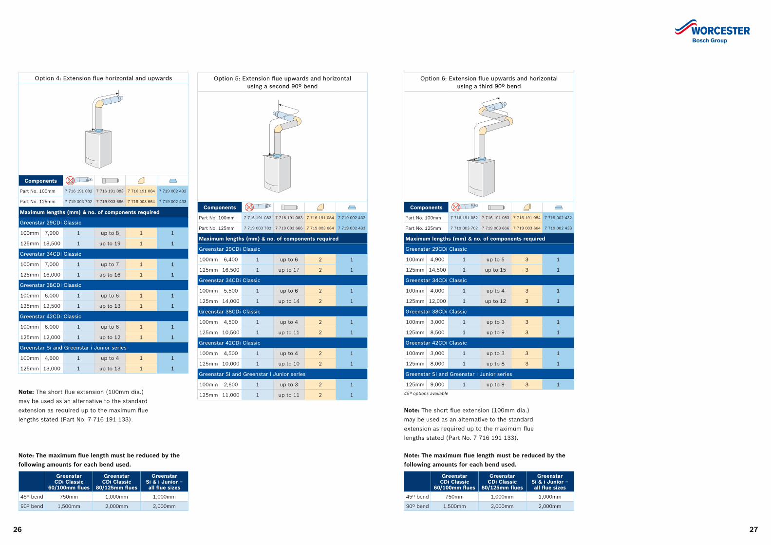
Note: The maximum flue length must be reduced by the
following amounts for each bend used.
Greenstar CDi Classic
60/100mm flues
Greenstar CDi Classic
80/125mm flues
Greenstar Si & i Junior – all flue sizes
45º bend 750mm 1,000mm 1,000mm
90º bend 1,500mm 2,000mm 2,000mm
™
™
2726
Note: The short flue extension (100mm dia.)
may be used as an alternative to the standard
extension as required up to the maximum flue
lengths stated (Part No. 7 716 191 133).
Note: The short flue extension (100mm dia.)
may be used as an alternative to the standard
extension as required up to the maximum flue
lengths stated (Part No. 7 716 191 133).
Option 4: Extension flue horizontal and upwards
Components
Part No. 100mm 7 716 191 082 7 716 191 083 7 716 191 084 7 719 002 432
Part No. 125mm 7 719 003 702 7 719 003 666 7 719 003 664 7 719 002 433
Maximum lengths (mm) & no. of components required
Greenstar 29CDi Classic
100mm 7,900 1 up to 8 1 1
125mm 18,500 1 up to 19 1 1
Greenstar 34CDi Classic
100mm 7,000 1 up to 7 1 1
125mm 16,000 1 up to 16 1 1
Greenstar 38CDi Classic
100mm 6,000 1 up to 6 1 1
125mm 12,500 1 up to 13 1 1
Greenstar 42CDi Classic
100mm 6,000 1 up to 6 1 1
125mm 12,000 1 up to 12 1 1
Greenstar Si and Greenstar i Junior series
100mm 4,600 1 up to 4 1 1
125mm 13,000 1 up to 13 1 1
Min.120mm
Min.120mm
Min.120mm
300mm
500mm
Pitchedroof
Flat roof
Min.120mm
Min.120mm
Min.120mm
Min.120mm
Min.120mm
300mm
500mm
Pitchedroof
Flat roof
Min.120mm
Min.120mm
Min.120mm
Min.120mm
Min.120mm
300mm
500mm
Pitchedroof
Flat roof
Min.120mm
Min.120mm
Option 5: Extension flue upwards and horizontal using a second 90º bend
Components
Part No. 100mm 7 716 191 082 7 716 191 083 7 716 191 084 7 719 002 432
Part No. 125mm 7 719 003 702 7 719 003 666 7 719 003 664 7 719 002 433
Maximum lengths (mm) & no. of components required
Greenstar 29CDi Classic
100mm 6,400 1 up to 6 2 1
125mm 16,500 1 up to 17 2 1
Greenstar 34CDi Classic
100mm 5,500 1 up to 6 2 1
125mm 14,000 1 up to 14 2 1
Greenstar 38CDi Classic
100mm 4,500 1 up to 4 2 1
125mm 10,500 1 up to 11 2 1
Greenstar 42CDi Classic
100mm 4,500 1 up to 4 2 1
125mm 10,000 1 up to 10 2 1
Greenstar Si and Greenstar i Junior series
100mm 2,600 1 up to 3 2 1
125mm 11,000 1 up to 11 2 1
Min.120mm
Min.120mm
Min.120mm
300mm
500mm
Pitchedroof
Flat roof
Min.120mm
Min.120mm
Min.120mm
Min.120mm
Min.120mm
300mm
500mm
Pitchedroof
Flat roof
Min.120mm
Min.120mm
Min.120mm
Min.120mm
Min.120mm
300mm
500mm
Pitchedroof
Flat roof
Min.120mm
Min.120mm
Option 6: Extension flue upwards and horizontal using a third 90º bend
Components
Part No. 100mm 7 716 191 082 7 716 191 083 7 716 191 084 7 719 002 432
Part No. 125mm 7 719 003 702 7 719 003 666 7 719 003 664 7 719 002 433
Maximum lengths (mm) & no. of components required
Greenstar 29CDi Classic
100mm 4,900 1 up to 5 3 1
125mm 14,500 1 up to 15 3 1
Greenstar 34CDi Classic
100mm 4,000 1 up to 4 3 1
125mm 12,000 1 up to 12 3 1
Greenstar 38CDi Classic
100mm 3,000 1 up to 3 3 1
125mm 8,500 1 up to 9 3 1
Greenstar 42CDi Classic
100mm 3,000 1 up to 3 3 1
125mm 8,000 1 up to 8 3 1
Greenstar Si and Greenstar i Junior series
125mm 9,000 1 up to 9 3 1
45º options available
Min.120mm
Min.120mm
Min.120mm
300mm
500mm
Pitchedroof
Flat roof
Min.120mm
Min.120mm
Min.120mm
Min.120mm
Min.120mm
300mm
500mm
Pitchedroof
Flat roof
Min.120mm
Min.120mm
Min.120mm
Min.120mm
Min.120mm
300mm
500mm
Pitchedroof
Flat roof
Min.120mm
Min.120mm
Note: The maximum flue length must be reduced by the
following amounts for each bend used.
Greenstar CDi Classic
60/100mm flues
Greenstar CDi Classic
80/125mm flues
Greenstar Si & i Junior – all flue sizes
45º bend 750mm 1,000mm 1,000mm
90º bend 1,500mm 2,000mm 2,000mm
Note: The maximum flue length must be reduced by the
following amounts for each bend used.
Greenstar CDi Classic
60/100mm flues
Greenstar CDi Classic
80/125mm flues
Greenstar Si & i Junior – all flue sizes
45º bend 750mm 1,000mm 1,000mm
90º bend 1,500mm 2,000mm 2,000mm
2928
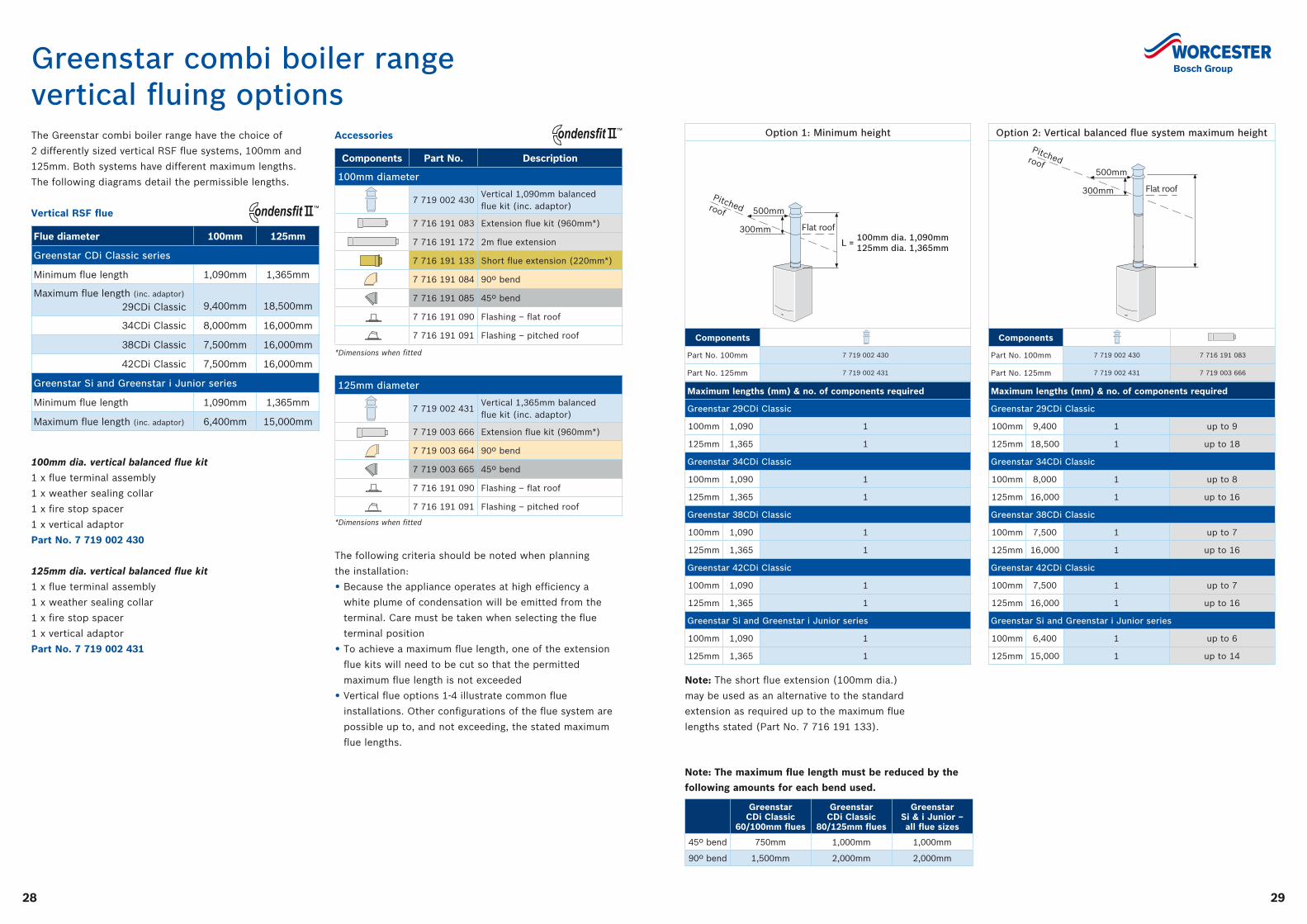
Greenstar combi boiler rangevertical fluing options The Greenstar combi boiler range have the choice of
2 differently sized vertical RSF flue systems, 100mm and
125mm. Both systems have different maximum lengths.
The following diagrams detail the permissible lengths.
Vertical RSF flue
100mm dia. vertical balanced flue kit
1 x flue terminal assembly
1 x weather sealing collar
1 x fire stop spacer
1 x vertical adaptor
Part No. 7 719 002 430
125mm dia. vertical balanced flue kit
1 x flue terminal assembly
1 x weather sealing collar
1 x fire stop spacer
1 x vertical adaptor
Part No. 7 719 002 431
Accessories
Note: The short flue extension (100mm dia.)
may be used as an alternative to the standard
extension as required up to the maximum flue
lengths stated (Part No. 7 716 191 133).
Option 1: Minimum height
Components
Part No. 100mm 7 719 002 430
Part No. 125mm 7 719 002 431
300mm
500mm
Flat roof
Pitchedroof
300mm
500mm
Pitchedroof
Flat roof
100mm dia. 1,090mm125mm dia. 1,365mmL =
Min.120mm
Min.120mm
Min.120mm
300mm
500mm
Pitchedroof
Flat roof
Min.120mm
Min.120mm
Maximum lengths (mm) & no. of components required
Greenstar 29CDi Classic
100mm 1,090 1
125mm 1,365 1
Greenstar 34CDi Classic
100mm 1,090 1
125mm 1,365 1
Greenstar 38CDi Classic
100mm 1,090 1
125mm 1,365 1
Greenstar 42CDi Classic
100mm 1,090 1
125mm 1,365 1
Greenstar Si and Greenstar i Junior series
100mm 1,090 1
125mm 1,365 1
Option 2: Vertical balanced flue system maximum height
Components
Part No. 100mm 7 719 002 430 7 716 191 083
Part No. 125mm 7 719 002 431 7 719 003 666
Maximum lengths (mm) & no. of components required
Greenstar 29CDi Classic
100mm 9,400 1 up to 9
125mm 18,500 1 up to 18
Greenstar 34CDi Classic
100mm 8,000 1 up to 8
125mm 16,000 1 up to 16
Greenstar 38CDi Classic
100mm 7,500 1 up to 7
125mm 16,000 1 up to 16
Greenstar 42CDi Classic
100mm 7,500 1 up to 7
125mm 16,000 1 up to 16
Greenstar Si and Greenstar i Junior series
100mm 6,400 1 up to 6
125mm 15,000 1 up to 14
Min.120mm
Min.120mm
Min.120mm
300mm
500mm
Pitchedroof
Flat roof
Min.120mm
Min.120mm
Min.120mm
Min.120mm
Min.120mm
300mm
500mm
Pitchedroof
Flat roof
Min.120mm
Min.120mm
300mm
500mm
Flat roof
Pitchedroof
300mm
500mm
Pitchedroof
Flat roof
100mm dia. 1,090mm125mm dia. 1,365mmL =
Components Part No. Description
100mm diameter
7 719 002 430Vertical 1,090mm balanced flue kit (inc. adaptor)
7 716 191 083 Extension flue kit (960mm*)
7 716 191 172 2m flue extension
7 716 191 133 Short flue extension (220mm*)
7 716 191 084 90º bend
7 716 191 085 45º bend
7 716 191 090 Flashing – flat roof
7 716 191 091 Flashing – pitched roof
*Dimensions when fitted
125mm diameter
7 719 002 431Vertical 1,365mm balanced flue kit (inc. adaptor)
7 719 003 666 Extension flue kit (960mm*)
7 719 003 664 90º bend
7 719 003 665 45º bend
7 716 191 090 Flashing – flat roof
7 716 191 091 Flashing – pitched roof
*Dimensions when fitted
Min.120mm
Min.120mm
Min.120mm
300mm
500mm
Pitchedroof
Flat roof
Min.120mm
Min.120mm
Min.120mm
Min.120mm
Min.120mm
300mm
500mm
Pitchedroof
Flat roof
Min.120mm
Min.120mm
Min.120mm
Min.120mm
Min.120mm
300mm
500mm
Pitchedroof
Flat roof
Min.120mm
Min.120mm
Min.120mm
Min.120mm
Min.120mm
300mm
500mm
Pitchedroof
Flat roof
Min.120mm
Min.120mm
Min.120mm
Min.120mm
Min.120mm
300mm
500mm
Pitchedroof
Flat roof
Min.120mm
Min.120mm
Min.120mm
Min.120mm
Min.120mm
300mm
500mm
Pitchedroof
Flat roof
Min.120mm
Min.120mm
Min.120mm
Min.120mm
Min.120mm
300mm
500mm
Pitchedroof
Flat roof
Min.120mm
Min.120mm
300mm
500mm
Flat roof
Pitchedroof
300mm
500mm
Pitchedroof
Flat roof
100mm dia. 1,090mm125mm dia. 1,365mmL =
300mm
500mm
Flat roof
Pitchedroof
300mm
500mm
Pitchedroof
Flat roof
100mm dia. 1,090mm125mm dia. 1,365mmL =
300mm
500mm
Flat roof
Pitchedroof
300mm
500mm
Pitchedroof
Flat roof
100mm dia. 1,090mm125mm dia. 1,365mmL =
300mm
500mm
Flat roof
Pitchedroof
300mm
500mm
Pitchedroof
Flat roof
100mm dia. 1,090mm125mm dia. 1,365mmL =
Min.120mm
Min.120mm
Min.120mm
300mm
500mm
Pitchedroof
Flat roof
Min.120mm
Min.120mm
Min.120mm
Min.120mm
Min.120mm
300mm
500mm
Pitchedroof
Flat roof
Min.120mm
Min.120mm
Note: The maximum flue length must be reduced by the
following amounts for each bend used.
Greenstar CDi Classic
60/100mm flues
Greenstar CDi Classic
80/125mm flues
Greenstar Si & i Junior – all flue sizes
45º bend 750mm 1,000mm 1,000mm
90º bend 1,500mm 2,000mm 2,000mm
Flue diameter 100mm 125mm
Greenstar CDi Classic series
Minimum flue length 1,090mm 1,365mm
Maximum flue length (inc. adaptor) 29CDi Classic
9,400mm
18,500mm
34CDi Classic 8,000mm 16,000mm
38CDi Classic 7,500mm 16,000mm
42CDi Classic 7,500mm 16,000mm
Greenstar Si and Greenstar i Junior series
Minimum flue length 1,090mm 1,365mm
Maximum flue length (inc. adaptor) 6,400mm 15,000mm
™
™
The following criteria should be noted when planning
the installation:
• Because the appliance operates at high efficiency a
white plume of condensation will be emitted from the
terminal. Care must be taken when selecting the flue
terminal position
• To achieve a maximum flue length, one of the extension
flue kits will need to be cut so that the permitted
maximum flue length is not exceeded
• Vertical flue options 1-4 illustrate common flue
installations. Other configurations of the flue system are
possible up to, and not exceeding, the stated maximum
flue lengths.
3130
Note: The short flue extension (100mm dia.)
may be used as an alternative to the standard
extension as required up to the maximum flue
lengths stated (Part No. 7 716 191 133).
Option 3: Vertical balanced flue system with two 45º bends
Components
Part No. 100mm 7 719 002 430 7 716 191 083 7 716 191 085
Part No. 125mm 7 719 002 431 7 719 003 666 7 719 003 665
Maximum lengths (mm) & no. of components required
Greenstar 29CDi Classic
100mm 7,900 1 up to 7 2
125mm 16,500 1 up to 16 2
Greenstar 34CDi Classic
100mm 6,500 1 up to 6 2
125mm 14,000 1 up to 14 2
Greenstar 38CDi Classic
100mm 6,000 1 up to 6 2
125mm 14,000 1 up to 14 2
Greenstar 42CDi Classic
100mm 6,000 1 up to 6 2
125mm 14,000 1 up to 14 2
Greenstar Si and Greenstar i Junior series
100mm 4,400 1 up to 4 2
125mm 13,000 1 up to 13 2
Min.120mm
Min.120mm
Min.120mm
300mm
500mm
Pitchedroof
Flat roof
Min.120mm
Min.120mm
Min.120mm
Min.120mm
Min.120mm
300mm
500mm
Pitchedroof
Flat roof
Min.120mm
Min.120mm
Min.120mm
Min.120mm
Min.120mm
300mm
500mm
Pitchedroof
Flat roof
Min.120mm
Min.120mm
300mm
500mm
Flat roof
Pitchedroof
300mm
500mm
Pitchedroof
Flat roof
100mm dia. 1,090mm125mm dia. 1,365mmL =
Option 4: Vertical balanced flue system with two 90º bends
Components
Part No. 100mm 7 719 002 430 7 716 191 083 7 716 191 084
Part No. 125mm 7 719 002 431 7 719 003 666 7 719 003 664
Maximum lengths (mm) & no. of components required
Greenstar 29CDi Classic
100mm 6,400 1 up to 6 2
125mm 14,500 1 up to 14 2
Greenstar 34CDi Classic
100mm 5,000 1 up to 4 2
125mm 12,000 1 up to 11 2
Greenstar 38CDi Classic
100mm 4,500 1 up to 4 2
125mm 12,000 1 up to 11 2
Greenstar 42CDi Classic
100mm 4,500 1 up to 4 2
125mm 12,000 1 up to 11 2
Greenstar Si and Greenstar i Junior series
100mm 2,400 1 up to 2 2
125mm 11,000 1 up to 10 2Min.120mm
Min.120mm
Min.120mm
300mm
500mm
Pitchedroof
Flat roof
Min.120mm
Min.120mm
Min.120mm
Min.120mm
Min.120mm
300mm
500mm
Pitchedroof
Flat roof
Min.120mm
Min.120mm
Min.120mm
Min.120mm
Min.120mm
300mm
500mm
Pitchedroof
Flat roof
Min.120mm
Min.120mm
300mm
500mm
Flat roof
Pitchedroof
300mm
500mm
Pitchedroof
Flat roof
100mm dia. 1,090mm125mm dia. 1,365mmL =
Note: The maximum flue length must be reduced by the
following amounts for each bend used.
Greenstar CDi Classic
60/100mm flues
Greenstar CDi Classic
80/125mm flues
Greenstar Si & i Junior – all flue sizes
45º bend 750mm 1,000mm 1,000mm
90º bend 1,500mm 2,000mm 2,000mm
Plume management terminal positioning
200300
150
200
8
4
5
3
2
9
200
600300300
150150
300300
25
25
1501,200
300
200
10
100600
Plume re-direction:
180°
±80°
1
7
±45°
Flue exhaustoutlet
Air intake
6
10
Boundary line
150
300
300
Flue terminal guard 7 716 191 176
600
1,500
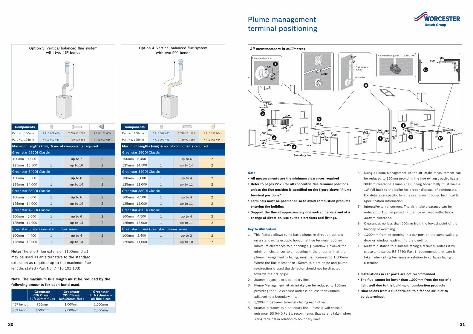
All measurements in millimetres
Note
• All measurements are the minimum clearances required
• Refer to pages 22-23 for all concentric flue terminal positions
unless the flue position is specified on the figure above “Plume
terminal positions”
• Terminals must be positioned so to avoid combustion products
entering the building
• Support the flue at approximately one metre intervals and at a
change of direction, use suitable brackets and fittings.
Key to illustration
1. This feature allows some basic plume re-direction options
on a standard telescopic horizontal flue terminal. 300mm
minimum clearances to a opening e.g. window. However the
minimum clearances to an opening in the direction that the
plume management is facing, must be increased to 1,500mm.
Where the flue is less than 150mm to a drainpipe and plume
re-direction is used the deflector should not be directed
towards the drainpipe.
2. 300mm adjacent to a boundary line.
3. Plume Management kit air intake can be reduced to 150mm
providing the flue exhaust outlet is no less than 300mm
adjacent to a boundary line.
4. 1,200mm between terminals facing each other.
5. 600mm distance to a boundary line, unless it will cause a
nuisance. BS 5440:Part 1 recommends that care is taken when
siting terminal in relation to boundary lines.
6. Using a Plume Management kit the air intake measurement can
be reduced to 150mm providing the flue exhaust outlet has a
300mm clearance. Plume kits running horizontally must have a
10° fall back to the boiler for proper disposal of condensate.
For details on specific lengths see relevant boiler Technical &
Specification information.
7. Internal/external corners. The air intake clearance can be
reduced to 150mm providing the flue exhaust outlet has a
300mm clearance.
8. Clearances no less than 200mm from the lowest point of the
balcony or overhang.
9. 1,200mm from an opening in a car port on the same wall e.g.
door or window leading into the dwelling.
10. 600mm distance to a surface facing a terminal, unless it will
cause a nuisance. BS 5440: Part 1 recommends that care is
taken when siting terminals in relation to surfaces facing
a terminal.
• Installations in car ports are not recommended
• The flue cannot be lower than 1,000mm from the top of a
light well due to the build up of combustion products
• Dimensions from a flue terminal to a fanned air inlet to
be determined.
3332
Plume management system options
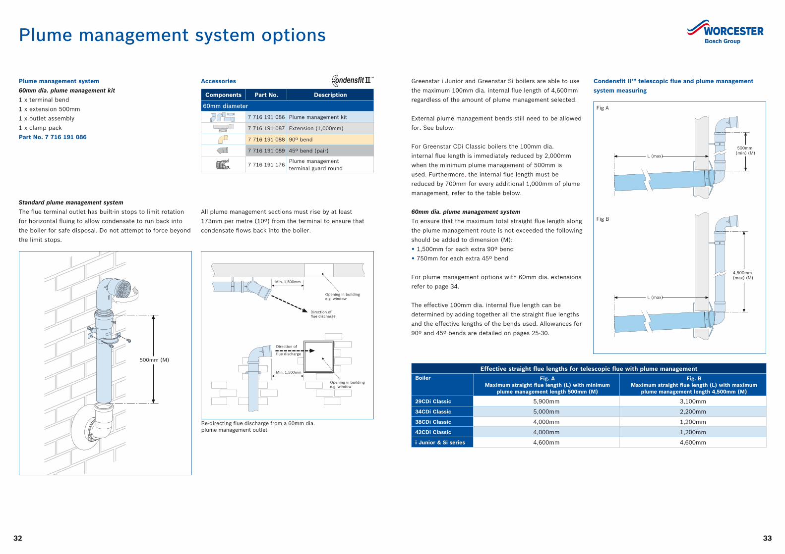
Plume management system
60mm dia. plume management kit
1 x terminal bend
1 x extension 500mm
1 x outlet assembly
1 x clamp pack
Part No. 7 716 191 086
Effective straight flue lengths for telescopic flue with plume managementBoiler Fig. A
Maximum straight flue length (L) with minimum plume management length 500mm (M)
Fig. B Maximum straight flue length (L) with maximum
plume management length 4,500mm (M)
29CDi Classic 5,900mm 3,100mm
34CDi Classic 5,000mm 2,200mm
38CDi Classic 4,000mm 1,200mm
42CDi Classic 4,000mm 1,200mm
i Junior & Si series 4,600mm 4,600mm
Components Part No. Description
60mm diameter
7 716 191 086 Plume management kit
7 716 191 087 Extension (1,000mm)
7 716 191 088 90º bend
7 716 191 089 45º bend (pair)
7 716 191 176Plume management terminal guard round
™
500mm (M)
Standard plume management system
The flue terminal outlet has built-in stops to limit rotation
for horizontal fluing to allow condensate to run back into
the boiler for safe disposal. Do not attempt to force beyond
the limit stops.
All plume management sections must rise by at least
173mm per metre (10º) from the terminal to ensure that
condensate flows back into the boiler.
L
500mm (min) (M)
L (max)
4,500mm (max) (M)
L (max)
Opening in buildinge.g. window
Opening in buildinge.g. window
Direction of flue discharge
Plume deflector
Min.1,500mm
Direction of flue discharge
Min. 1,500mm
Opening in buildinge.g. window
Direction of
flue discharge
Min. 1,500mm
Re-directing flue discharge from a 60mm dia. plume management outlet
Greenstar i Junior and Greenstar Si boilers are able to use
the maximum 100mm dia. internal flue length of 4,600mm
regardless of the amount of plume management selected.
External plume management bends still need to be allowed
for. See below.
For Greenstar CDi Classic boilers the 100mm dia.
internal flue length is immediately reduced by 2,000mm
when the minimum plume management of 500mm is
used. Furthermore, the internal flue length must be
reduced by 700mm for every additional 1,000mm of plume
management, refer to the table below.
60mm dia. plume management system
To ensure that the maximum total straight flue length along
the plume management route is not exceeded the following
should be added to dimension (M):
• 1,500mm for each extra 90º bend
• 750mm for each extra 45º bend
For plume management options with 60mm dia. extensions
refer to page 34.
The effective 100mm dia. internal flue length can be
determined by adding together all the straight flue lengths
and the effective lengths of the bends used. Allowances for
90º and 45º bends are detailed on pages 25-30.
Accessories Condensfit II™ telescopic flue and plume management
system measuring
Fig A
Fig B
3534
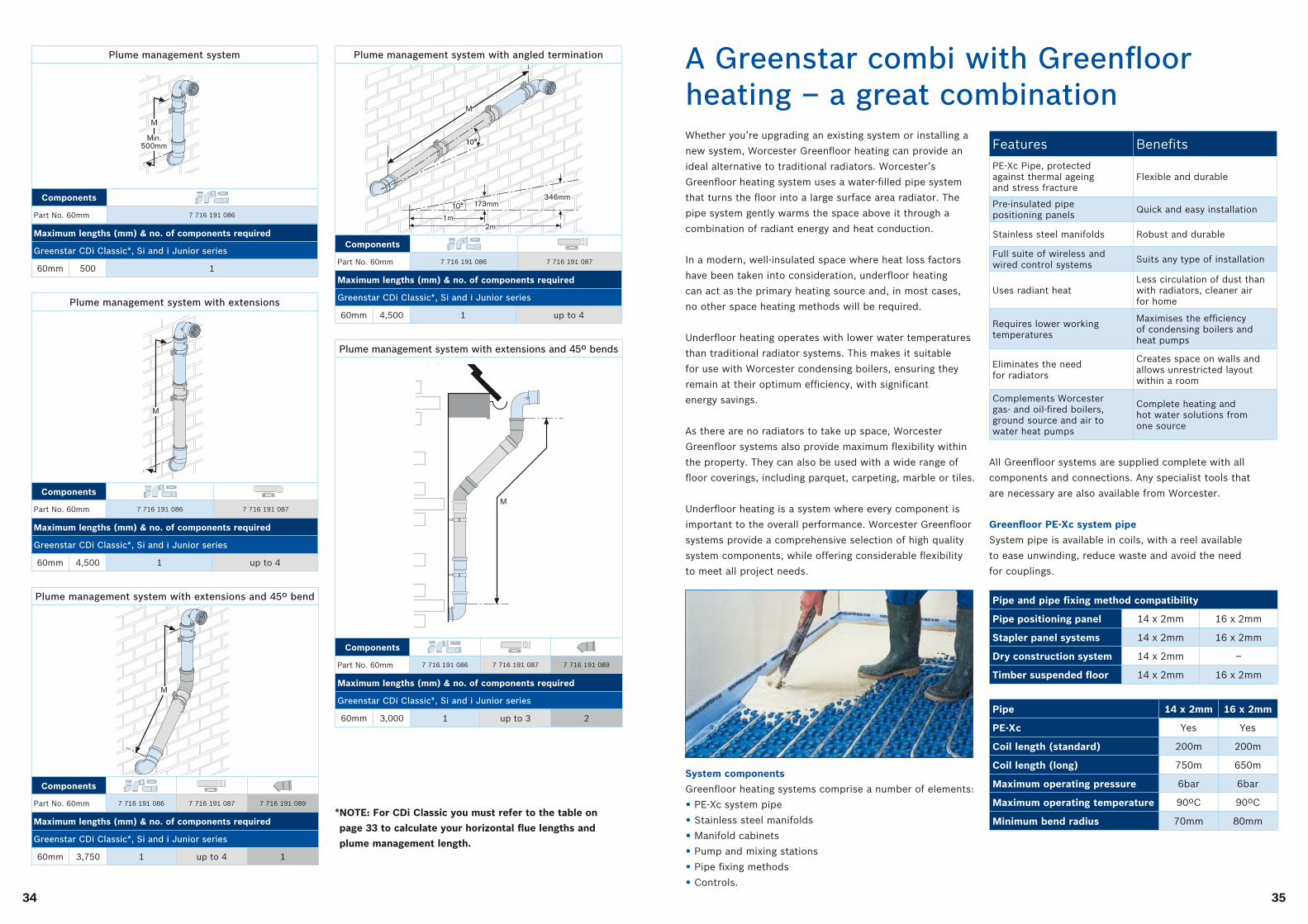
Plume management system with extensions
Components
Part No. 60mm 7 716 191 086 7 716 191 087
* NOTE: For CDi Classic you must refer to the table on
page 33 to calculate your horizontal flue lengths and
plume management length.
Plume management system
Components
Part No. 60mm 7 716 191 086
Maximum lengths (mm) & no. of components required
Greenstar CDi Classic*, Si and i Junior series
60mm 500 1
Maximum lengths (mm) & no. of components required
Greenstar CDi Classic*, Si and i Junior series
60mm 4,500 1 up to 4
Plume management system with extensions and 45º bend
Components
Part No. 60mm 7 716 191 086 7 716 191 087 7 716 191 089
Maximum lengths (mm) & no. of components required
Greenstar CDi Classic*, Si and i Junior series
60mm 3,750 1 up to 4 1
Plume management system with angled termination
Components
Part No. 60mm 7 716 191 086 7 716 191 087
Maximum lengths (mm) & no. of components required
Greenstar CDi Classic*, Si and i Junior series
60mm 4,500 1 up to 4
Plume management system with extensions and 45º bends
Components
Part No. 60mm 7 716 191 086 7 716 191 087 7 716 191 089
Maximum lengths (mm) & no. of components required
Greenstar CDi Classic*, Si and i Junior series
60mm 3,000 1 up to 3 2
Whether you’re upgrading an existing system or installing a
new system, Worcester Greenfloor heating can provide an
ideal alternative to traditional radiators. Worcester’s
Greenfloor heating system uses a water-filled pipe system
that turns the floor into a large surface area radiator. The
pipe system gently warms the space above it through a
combination of radiant energy and heat conduction.
In a modern, well-insulated space where heat loss factors
have been taken into consideration, underfloor heating
can act as the primary heating source and, in most cases,
no other space heating methods will be required.
Underfloor heating operates with lower water temperatures
than traditional radiator systems. This makes it suitable
for use with Worcester condensing boilers, ensuring they
remain at their optimum efficiency, with significant
energy savings.
As there are no radiators to take up space, Worcester
Greenfloor systems also provide maximum flexibility within
the property. They can also be used with a wide range of
floor coverings, including parquet, carpeting, marble or tiles.
Underfloor heating is a system where every component is
important to the overall performance. Worcester Greenfloor
systems provide a comprehensive selection of high quality
system components, while offering considerable flexibility
to meet all project needs.
System components
Greenfloor heating systems comprise a number of elements:
• PE-Xc system pipe
• Stainless steel manifolds
• Manifold cabinets
• Pump and mixing stations
• Pipe fixing methods
• Controls.
A Greenstar combi with Greenfloor heating – a great combination
Pipe and pipe fixing method compatibility
Pipe positioning panel 14 x 2mm 16 x 2mm
Stapler panel systems 14 x 2mm 16 x 2mm
Dry construction system 14 x 2mm –
Timber suspended floor 14 x 2mm 16 x 2mm
Pipe 14 x 2mm 16 x 2mm
PE-Xc Yes Yes
Coil length (standard) 200m 200m
Coil length (long) 750m 650m
Maximum operating pressure 6bar 6bar
Maximum operating temperature 90ºC 90ºC
Minimum bend radius 70mm 80mm
All Greenfloor systems are supplied complete with all
components and connections. Any specialist tools that
are necessary are also available from Worcester.
Greenfloor PE-Xc system pipe
System pipe is available in coils, with a reel available
to ease unwinding, reduce waste and avoid the need
for couplings.
Features Benefits
PE-Xc Pipe, protected against thermal ageing and stress fracture
Flexible and durable
Pre-insulated pipe positioning panels Quick and easy installation
Stainless steel manifolds Robust and durable
Full suite of wireless and wired control systems Suits any type of installation
Uses radiant heatLess circulation of dust than with radiators, cleaner air for home
Requires lower working temperatures
Maximises the efficiency of condensing boilers and heat pumps
Eliminates the need for radiators
Creates space on walls and allows unrestricted layout within a room
Complements Worcester gas- and oil-fired boilers, ground source and air to water heat pumps
Complete heating and hot water solutions from one source
3736
Greenstar combi installation requirements
Installation of the Greenstar combi boiler range must be
in accordance with the relevant requirements of the Gas
Safety (Installation Use) Regulations (as amended), current
IEE Wiring Regulations, local Building Regulations, Building
Standards (Scotland) regulations and bylaws of the local
Water company and Health and Safety Document No.
635 (Electricity at Work Regulations 1989). It should be
in accordance with the relevant recommendations of the
following British Standards:
BS 6798; EN 12828; BS 5546:1; BS 5440:1; BS 5440:2;
BS 6891; BS 7074; BS 7593.
Gas Safety (Installation and Use) Regulations. All gas
appliances must be installed by a Gas Safe registered
person in accordance with the above regulations. Failure
to install appliances correctly could lead to prosecution.
The manufacturer’s notes must not be taken in any way as
overriding statutory regulations.
Sealed primary systems
The Worcester Greenstar combi boilers are supplied
complete with all the necessary components to form a
sealed primary system. Included are an expansion vessel,
a pressure relief valve (set at 3bar), an automatic air vent
and a pressure gauge.
With an initial system pressure of 0.5bar a system capacity
of approximately 83 litres can be accommodated. Refer to
BS 7074:Part 1 for more information.
It is important with an aluminium heat exchanger that the
pH level of the water does not exceed 8. Levels in excess of
this could be detrimental to the heat exchanger.
The use of a suitable inhibitor will provide a resistance to
this. Contact Sentinel (Tel: 0800 3894670 or visit
www.sentinel-solutions.net) or Fernox (Tel: 0870 601 5000
or visit www.fernox.com) for further details.
System filling and re-pressurising
Worcester Greenstar combi boilers are fitted to a sealed
heating system which is pressurised. To maintain optimum
system pressure two options may be used: an optional
Worcester integral filling link or external filling loop.
Optional Worcester integral filling link
The Worcester integral filling
link simply connects between
the cold main connection
and the heating return circuit
on the wall mounting jig.
This feature is supplied as
standard with the Greenstar
CDi Classic and is available
as an accessory for the
Greenstar Si and i Junior
(part no. 7 716 192 281).
Valves and joints
It is very important that all valves and joints are able to
sustain a working pressure of up to 3bar (45psi). Particular
care should be exercised when fitting radiator valves and
only those of high quality to BS 2767:10 should be used.
All other valves and fittings should comply with BS 1010.
Loss of water pressure from a sealed system will require
continuous recharging with fresh water and consequential
introduction of air. Air is highly corrosive and will
considerably reduce life expectancy of radiators, pumps etc.
Plastic pipework
The use of plastic pipework is acceptable. However, some
plastics are permeable to oxygen and must be avoided. Only
pipework with a polymeric barrier should be used. Please
note that the first 600mm of pipework connected to the
boiler must be of copper or steel.
Natural gas supply
For the Greenstar i Junior when on a hot water or full
output demand will require up to 3.02m3/hr of gas
(depending on the model).
For the Greenstar Si when on a hot water or full output
demand will require up to 3.24m3/hr of gas (depending on
the model).
For the Greenstar CDi Classic 42kW appliance when on
a hot water or full output demand will require up to
4.4m3/hr of gas (figures for other appliances can be
found in the relevant installation manuals).
The gas meter and supply pipes must be capable of
supplying this quantity of gas in addition to the demand
from any other appliance being served. It is important that
a gas supply pipe of at least 22mm diameter is used. Under
no circumstances should the size of the gas supply pipe be
less than that of the appliance inlet connection. The meter
outlet governor should be capable of ensuring a dynamic
pressure of 20mbar (8in wg) at the appliance. Particular
consideration should be given to the resistance to gas flow
created by elbows, bends etc. Pipework should be sized to
overcome this resistance.
Liquid Petroleum Gas (LPG) supply
All Greenstar combi appliances are available in natural
gas and LPG variants. The appliance when on a hot water
or full output demand will require up to 2.22 kg/h of gas
(depending on the model). The Greenstar Si models will
require up to 2.38 kg/h of gas (depending on the model)
at maximum demand.
The Greenstar CDi Classic 42kW appliance when on a hot
water or full output demand will require up to 3.3 kg/h
of gas (figures for other appliances can be found in the
relevant installation manual).
The gas tank or bottles must be capable of supplying this
quantity of gas at a nominal pressure of 37mbar (14.8in
wg) at the appliance. The table below shows the LPG
gas discharge through varying lengths of pipe and the
resistance to flow created by elbows, bends etc.
Pipework should be sized to overcome this resistance.
Electricity supply
A 3amp fused three pin plug and unswitched shuttered
socket outlet (both complying with BS 1362) or preferably a
double pole isolator with a contact separation of 3mm in all
poles supplying the appliance should be used.
The appliance electrical circuits are also protected by an
internal 2amp fuse. The appliance must be earthed.
Mains cold water supply
Water Authority requirement
A direct mains cold water connection is permitted by
Water Authorities. However, it is recommended that
reference be made to local requirements. In the event of
difficulty contact Worcester Technical Support Department.
Cold water connection
Connection should be made as shown in the pipework
detail and the appliance installed generally in accordance
with the layout shown on page 17.
Wherever possible the cold supply to the appliance should
be the first connection off the mains supply, in order to
minimise hot water flow reduction when cold water services
are operated. The final 600mm of piping to the appliance
should be of copper only.
Cold water pressure
To achieve the stipulated flow rate a working cold water
mains pressure of 1.3bar is required.
However, for the Greenstar CDi Classic range to achieve the
stipulated flow rate a working cold water mains pressure of
between 1.2 and 2.3bar is required (dependent on model).
D
C
A
B
MAINS WATER EXPANSION VESSEL:A - Mini expansion vessel, Part No. 7 716 192 105B - Mains water inlet pipeC - Non-return valveD - Boiler
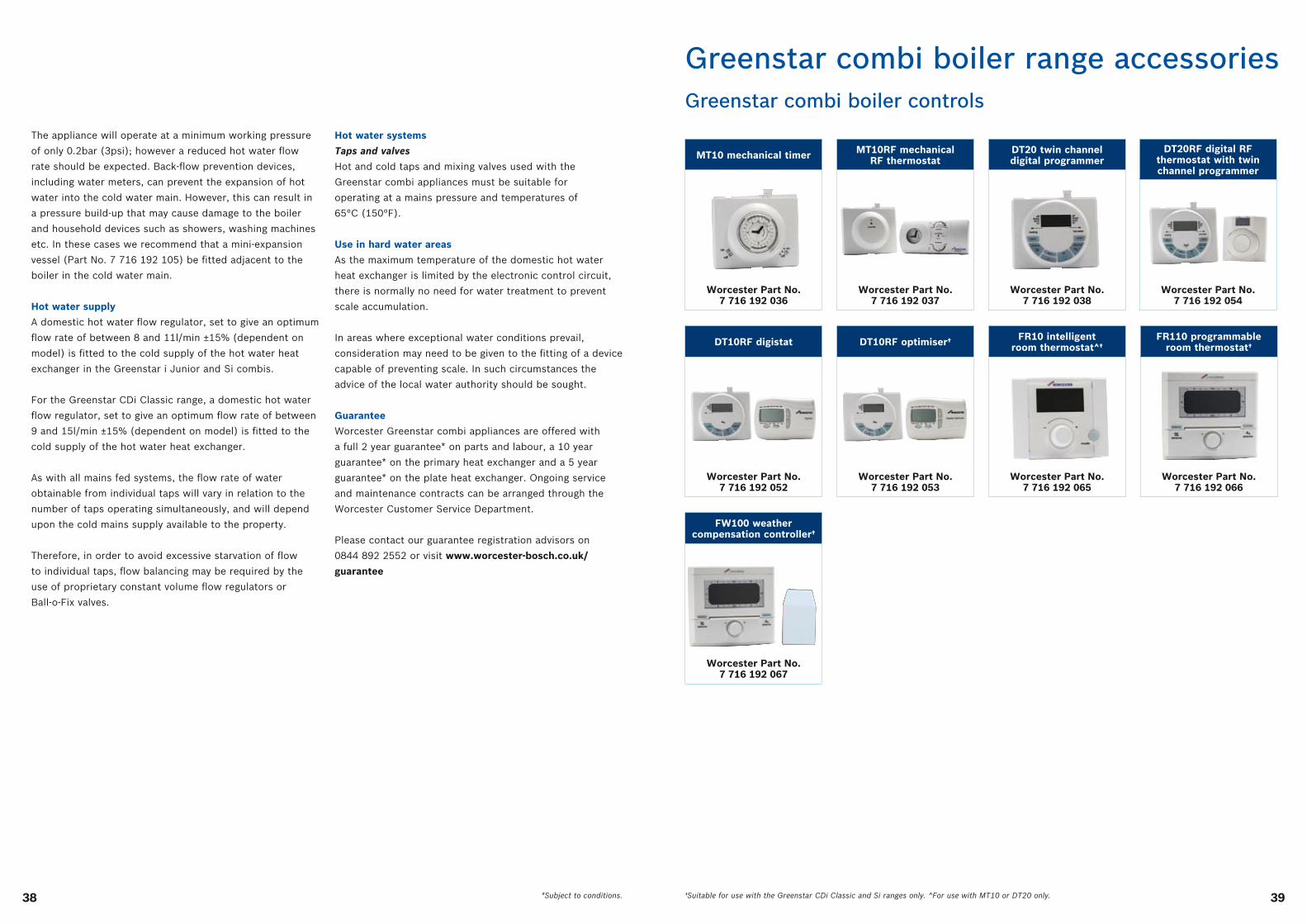
3938
The appliance will operate at a minimum working pressure
of only 0.2bar (3psi); however a reduced hot water flow
rate should be expected. Back-flow prevention devices,
including water meters, can prevent the expansion of hot
water into the cold water main. However, this can result in
a pressure build-up that may cause damage to the boiler
and household devices such as showers, washing machines
etc. In these cases we recommend that a mini-expansion
vessel (Part No. 7 716 192 105) be fitted adjacent to the
boiler in the cold water main.
Hot water supply
A domestic hot water flow regulator, set to give an optimum
flow rate of between 8 and 11l/min ±15% (dependent on
model) is fitted to the cold supply of the hot water heat
exchanger in the Greenstar i Junior and Si combis.
For the Greenstar CDi Classic range, a domestic hot water
flow regulator, set to give an optimum flow rate of between
9 and 15l/min ±15% (dependent on model) is fitted to the
cold supply of the hot water heat exchanger.
As with all mains fed systems, the flow rate of water
obtainable from individual taps will vary in relation to the
number of taps operating simultaneously, and will depend
upon the cold mains supply available to the property.
Therefore, in order to avoid excessive starvation of flow
to individual taps, flow balancing may be required by the
use of proprietary constant volume flow regulators or
Ball-o-Fix valves.
Hot water systems
Taps and valves
Hot and cold taps and mixing valves used with the
Greenstar combi appliances must be suitable for
operating at a mains pressure and temperatures of
65°C (150°F).
Use in hard water areas
As the maximum temperature of the domestic hot water
heat exchanger is limited by the electronic control circuit,
there is normally no need for water treatment to prevent
scale accumulation.
In areas where exceptional water conditions prevail,
consideration may need to be given to the fitting of a device
capable of preventing scale. In such circumstances the
advice of the local water authority should be sought.
Guarantee
Worcester Greenstar combi appliances are offered with
a full 2 year guarantee* on parts and labour, a 10 year
guarantee* on the primary heat exchanger and a 5 year
guarantee* on the plate heat exchanger. Ongoing service
and maintenance contracts can be arranged through the
Worcester Customer Service Department.
Please contact our guarantee registration advisors on
0844 892 2552 or visit www.worcester-bosch.co.uk/
guarantee
*Subject to conditions.
Greenstar combi boiler range accessoriesGreenstar combi boiler controls
MT10 mechanical timer
Worcester Part No. 7 716 192 036
DT10RF digistat
Worcester Part No. 7 716 192 052
MT10RF mechanical RF thermostat
Worcester Part No. 7 716 192 037
DT10RF optimiser†
Worcester Part No. 7 716 192 053
DT20 twin channeldigital programmer
Worcester Part No. 7 716 192 038
DT20RF digital RF thermostat with twin channel programmer
Worcester Part No. 7 716 192 054
FR10 intelligent room thermostat^†
Worcester Part No. 7 716 192 065
FR110 programmableroom thermostat†
Worcester Part No. 7 716 192 066
FW100 weather compensation controller†
Worcester Part No. 7 716 192 067
†Suitable for use with the Greenstar CDi Classic and Si ranges only. ^For use with MT10 or DT20 only.
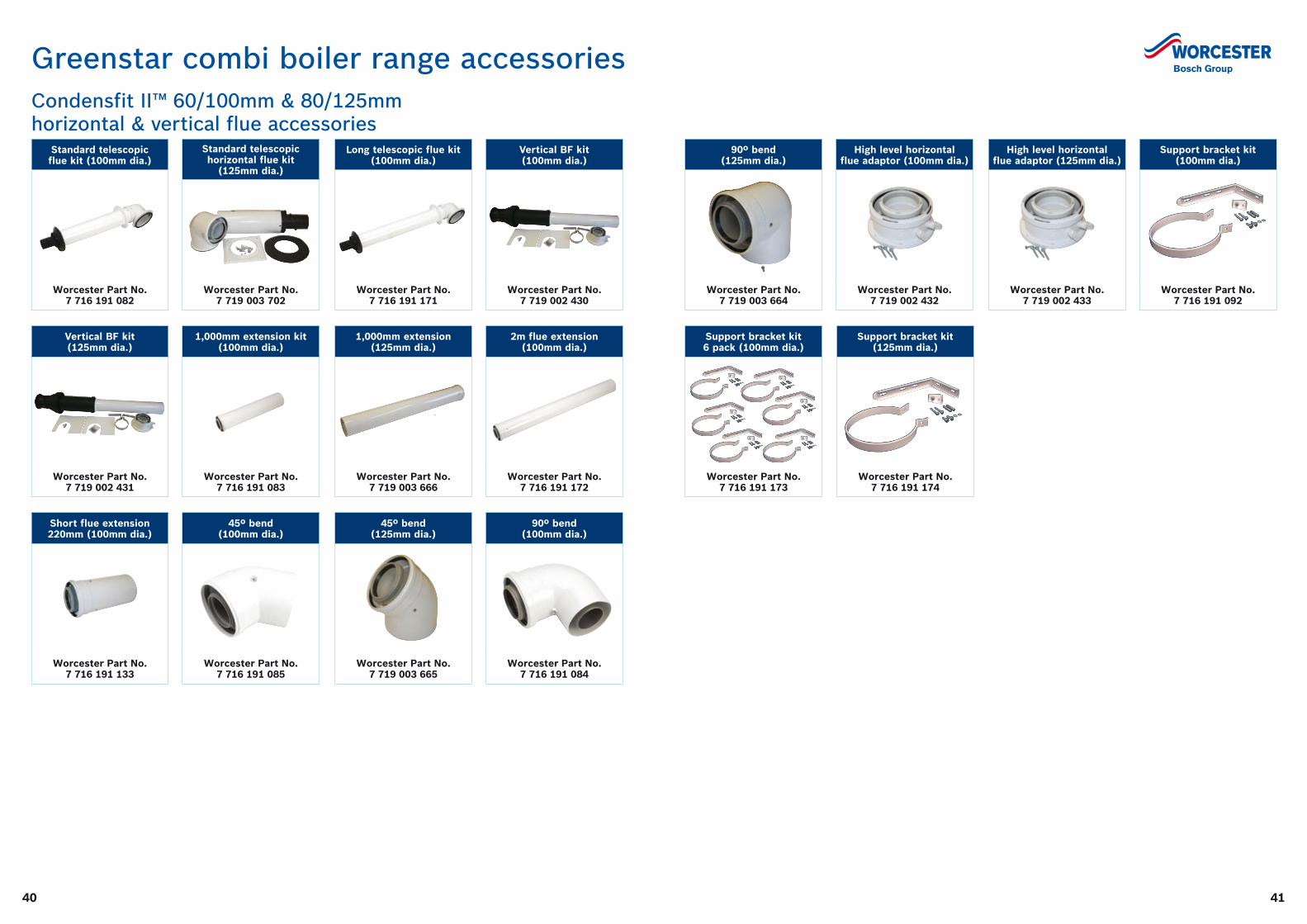
4140
Standard telescopic horizontal flue kit
(125mm dia.)
Worcester Part No. 7 719 003 702
1,000mm extension kit (100mm dia.)
Worcester Part No. 7 716 191 083
45º bend (100mm dia.)
Worcester Part No. 7 716 191 085
Long telescopic flue kit (100mm dia.)
Worcester Part No. 7 716 191 171
1,000mm extension (125mm dia.)
Worcester Part No. 7 719 003 666
45º bend (125mm dia.)
Worcester Part No. 7 719 003 665
Vertical BF kit (100mm dia.)
Worcester Part No. 7 719 002 430
2m flue extension (100mm dia.)
Worcester Part No. 7 716 191 172
90º bend (100mm dia.)
Worcester Part No. 7 716 191 084
Standard telescopic flue kit (100mm dia.)
Worcester Part No. 7 716 191 082
Vertical BF kit (125mm dia.)
Worcester Part No. 7 719 002 431
Short flue extension 220mm (100mm dia.)
Worcester Part No. 7 716 191 133
Greenstar combi boiler range accessoriesCondensfit II™ 60/100mm & 80/125mm horizontal & vertical flue accessories
Support bracket kit 6 pack (100mm dia.)
Worcester Part No. 7 716 191 173
Support bracket kit (125mm dia.)
Worcester Part No. 7 716 191 174
High level horizontal flue adaptor (100mm dia.)
Worcester Part No. 7 719 002 432
High level horizontal flue adaptor (125mm dia.)
Worcester Part No. 7 719 002 433
Support bracket kit (100mm dia.)
Worcester Part No. 7 716 191 092
90º bend (125mm dia.)
Worcester Part No. 7 719 003 664
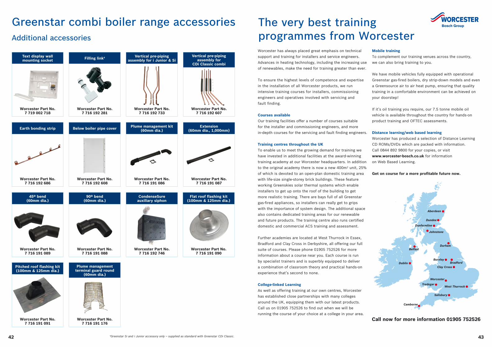
4342
Greenstar combi boiler range accessoriesAdditional accessories
Plume management kit (60mm dia.)
Worcester Part No. 7 716 191 086
Vertical pre-piping assembly for i Junior & Si
Worcester Part No. 7 716 192 733
Vertical pre-piping assembly for
CDi Classic combi
Worcester Part No. 7 716 192 607
Extension (60mm dia., 1,000mm)
Worcester Part No. 7 716 191 087
Text display wall mounting socket
Worcester Part No. 7 719 002 718
Earth bonding strip
Worcester Part No. 7 716 192 686
90º bend (60mm dia.)
Worcester Part No. 7 716 191 088
Flat roof flashing kit (100mm & 125mm dia.)
Worcester Part No. 7 716 191 090
Pitched roof flashing kit (100mm & 125mm dia.)
Worcester Part No. 7 716 191 091
Plume management terminal guard round
(60mm dia.)
Worcester Part No. 7 716 191 176
Filling link†
Worcester Part No. 7 716 192 281
Below boiler pipe cover
Worcester Part No. 7 716 192 608
45º bend (60mm dia.)
Worcester Part No. 7 716 191 089
CondenseSure auxiliary siphon
Worcester Part No. 7 716 192 746
†Greenstar Si and i Junior accessory only – supplied as standard with Greenstar CDi Classic.
The very best training programmes from Worcester Worcester has always placed great emphasis on technical
support and training for installers and service engineers.
Advances in heating technology, including the increasing use
of renewables, make the need for training greater than ever.
To ensure the highest levels of competence and expertise
in the installation of all Worcester products, we run
intensive training courses for installers, commissioning
engineers and operatives involved with servicing and
fault finding.
Courses available
Our training facilities offer a number of courses suitable
for the installer and commissioning engineers, and more
in-depth courses for the servicing and fault finding engineers.
Training centres throughout the UK
To enable us to meet the growing demand for training we
have invested in additional facilities at the award-winning
training academy at our Worcester headquarters. In addition
to the original academy there is now a new 400m2 unit, 25%
of which is devoted to an open-plan domestic training area
with life-size single-storey brick buildings. These feature
working Greenskies solar thermal systems which enable
installers to get up onto the roof of the building to get
more realistic training. There are bays full of all Greenstar
gas-fired appliances, so installers can really get to grips
with the importance of system design. The additional space
also contains dedicated training areas for our renewable
and future products. The training centre also runs certified
domestic and commercial ACS training and assessment.
Further academies are located at West Thurrock in Essex,
Bradford and Clay Cross in Derbyshire, all offering our full
suite of courses. Please phone 01905 752526 for more
information about a course near you. Each course is run
by specialist trainers and is superbly equipped to deliver
a combination of classroom theory and practical hands-on
experience that’s second to none.
College-linked Learning
As well as offering training at our own centres, Worcester
has established close partnerships with many colleges
around the UK, equipping them with our latest products.
Call us on 01905 752526 to find out when we will be
running the course of your choice at a college in your area.
Belfast
Bradford
Clay Cross
Worcester
West Thurrock
Dundee
Dublin
Aberdeen
Dunfermline
Burnley
Durham
Salisbury
Tredegar
Camborne
Johnstone
Mobile training
To complement our training venues across the country,
we can also bring training to you.
We have mobile vehicles fully equipped with operational
Greenstar gas-fired boilers, dry strip-down models and even
a Greensource air to air heat pump, ensuring that quality
training in a comfortable environment can be achieved on
your doorstep!
If it’s oil training you require, our 7.5 tonne mobile oil
vehicle is available throughout the country for hands-on
product training and OFTEC assessments.
Distance learning/web based learning
Worcester has produced a selection of Distance Learning
CD ROMs/DVDs which are packed with information.
Call 0844 892 9800 for your copies, or visit
www.worcester-bosch.co.uk for information
on Web Based Learning.
Get on course for a more profitable future now.
Call now for more information 01905 752526
Worcester training coursesOne stop shop training
We are here to provide you with training and assistance for all areas of your business, not just product training.
Call us on 01905 752526 to order a full training course brochure.
Boiler training courses
Greenstar CDi Classic gas-fired condensing combi boilers
Models covered Whole Greenstar CDi Classic range Duration: 1 day
Greenstar i Junior & Si gas-fired condensing combi boilers
Models covered Greenstar 24/28i Junior and Greenstar 25/30Si Duration: 1 day
Greenstar Highflow CDi & FS CDi regular floor standing gas-fired condensing combi and regular boilers
Models covered Greenstar Highflow 440/550CDi and Greenstar FS 30/42CDi Regular Duration: 1 day
Greenstar system & regular gas-fired condensing boilers
Models covered Greenstar 12/15/18/24Ri, Greenstar 30/40CDi Regular, Greenstar FS 30/42CDi Regular, Greenstar 30CDi System and Greenstar 12/15/18/24i System
Duration: 1 day
Greenstar Danesmoor, Heatslave & Camray high efficiency condensing oil-fired boilers – pre-OFTEC training
Models covered Greenstar Danesmoor series, Greenstar Heatslave series and Greenstar Camray series Duration: 1 day
Greenstar controls
Models covered MT10, MT10RF, DT20RF, DT20, DT10RF, TD200, RT10, FR10, FR110, FW100 and ISM1 Duration: 1 day
GB162 gas-fired condensing boilers
Models covered GB162 65kW Duration: 1 day
GB162 gas-fired condensing boilers – cascade
Models covered GB162 65/80/100kW – cascading up to 800kW Duration: 1 day
Greenspring CWi47 – gas-fired condensing instantaneous water heater
Models covered CWi47 Duration: 1 day
Renewable training courses
Greenskies solar hot water system
Covering Installation, commissioning and servicing Duration: 2 days
Greenskies advanced solar
Covering Worcester solar control range and pump stations Duration: 1 days
Greenstore ground source heat pumps
Covering Installation, commissioning and system design Duration: 2 days
Greensource heat pumps – air to water
Covering Installation, commissioning and system design Duration: 2 days
Greensource heat pumps – air to air
Covering Installation, commissioning and system design Duration: 1 day
Greenfloor heating
Covering Installation, commissioning and servicing Duration: 1 day
4544
Industry focused training courses
BPEC warm water underfloor heating installation
Covering Basic principles & advantages of underfloor heating, floor systems and finishes, operation, installation, testing and post installation activities
Duration: 2 days
BPEC ventilation
Covering Installation, commissioning, inspection and testing Duration: 2 days
Hot water systems & safety
Covering All G3 Regulations for the installation, servicing and commissioning of unvented cylinders. This course is certified by Logic Certification.
Duration: 1 day
Chemical water treatment
Covering Water treatment of domestic heating systems in accordance with BS 7593: 2006 Duration: 1 day
Construction skills F-Gas training/assessment certification
Covering Qualifies for Construction Skills Certification & Registration (valid for 5 years) and Voluntary ACRIB Registration
Duration: 4 days
Please note to attend OFTEC courses you must have a minimum of 12 months’ experience installing/servicing oil boilers. For inexperienced candidates, our Greenstar Danesmoor, Heatslave and Camray course offers pre-OFTEC training. For experienced oil technicians training is not a pre-requisite for OFTEC assessment.
OFTEC training and assessment
OFTEC 101
Covering Domestic/light commercial pressure jet commissioning and servicing Duration: 3 days
OFTEC 105e
Covering Domestic/light commercial pressure jet boiler installation Duration: 1 day assessment
OFTEC 101 & 105e
Covering Domestic/light commercial pressure jet installation, commissioning and servicing Duration: 3 days
OFTEC 600a
Covering Oil tank installation and associated controls Duration: 1 day assessment
OFTEC 101/105e/600e
Covering Domestic/light commercial pressure jet boiler installation, commissioning, servicing and oil tank installation and associated controls
Duration: 4 days
Mobile OFTEC
All above covered throughout the country on the mobile training vehicle as well as in all our centres
Commercial ACS training and assessment
CODNCO1
Covering Changeover qualification from domestic to commercial, including CIGA1, ICPN1, TPCP1A Duration: 4 days
Domestic ACS training and assessment
Reassessment CCN1 + 3 appliances
Covering Re-assessment for candidates whose CCN1 qualification expires in less than 12 months Duration: 4 days
Heating design course
IDHEE domestic heating design course
Covering To allow installers, specifiers and heating engineers to design and specify heating systems correctly Duration: 9 weeks*
*Distance learning and 4 x classroom based sessions are spread evenly across 9 weeks with a three week break between each session. There is a final written assessment following the final session.
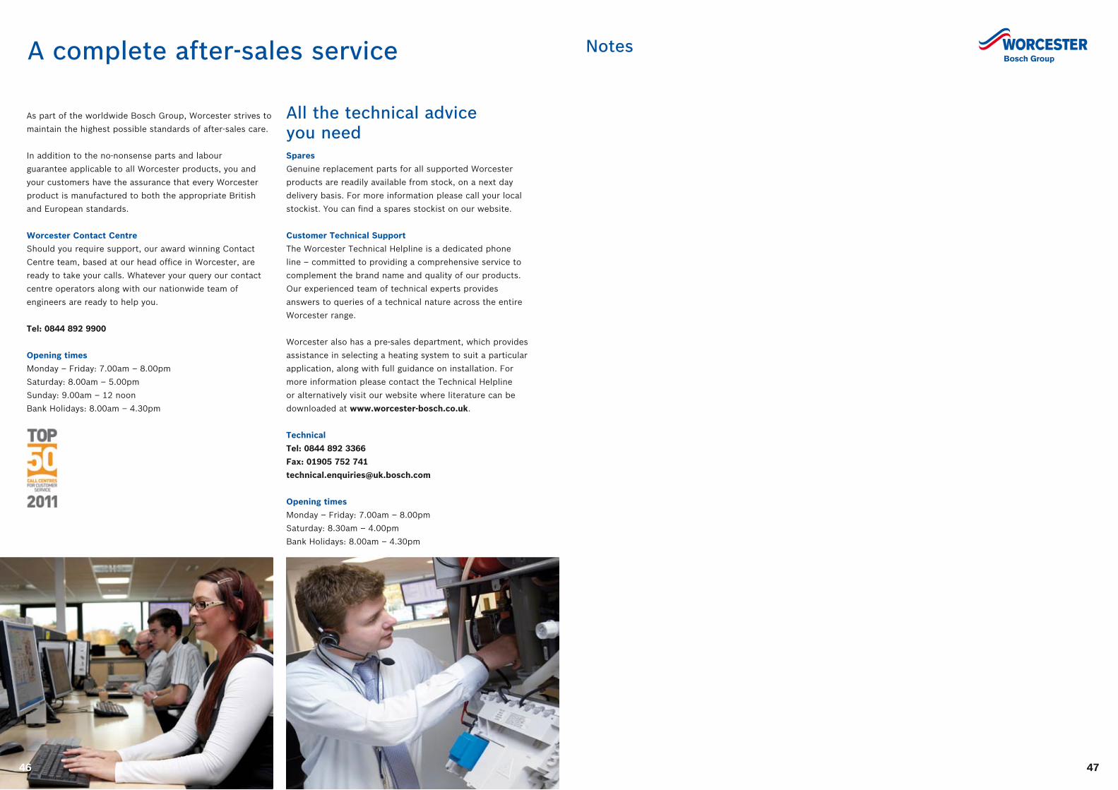
A complete after-sales service
All the technical advice you needSpares
Genuine replacement parts for all supported Worcester
products are readily available from stock, on a next day
delivery basis. For more information please call your local
stockist. You can find a spares stockist on our website.
Customer Technical Support
The Worcester Technical Helpline is a dedicated phone
line – committed to providing a comprehensive service to
complement the brand name and quality of our products.
Our experienced team of technical experts provides
answers to queries of a technical nature across the entire
Worcester range.
Worcester also has a pre-sales department, which provides
assistance in selecting a heating system to suit a particular
application, along with full guidance on installation. For
more information please contact the Technical Helpline
or alternatively visit our website where literature can be
downloaded at www.worcester-bosch.co.uk.
Technical
Tel: 0844 892 3366
Fax: 01905 752 741
Opening times
Monday – Friday: 7.00am – 8.00pm
Saturday: 8.30am – 4.00pm
Bank Holidays: 8.00am – 4.30pm
As part of the worldwide Bosch Group, Worcester strives to
maintain the highest possible standards of after-sales care.
In addition to the no-nonsense parts and labour
guarantee applicable to all Worcester products, you and
your customers have the assurance that every Worcester
product is manufactured to both the appropriate British
and European standards.
Worcester Contact Centre
Should you require support, our award winning Contact
Centre team, based at our head office in Worcester, are
ready to take your calls. Whatever your query our contact
centre operators along with our nationwide team of
engineers are ready to help you.
Tel: 0844 892 9900
Opening times
Monday – Friday: 7.00am – 8.00pm
Saturday: 8.00am – 5.00pm
Sunday: 9.00am – 12 noon
Bank Holidays: 8.00am – 4.30pm
46 47
Notes
www.worcester-bosch.co.uk
Worcester, Bosch Group is a brand name of Bosch Thermotechnology Ltd.
This leaflet is accurate at the date of printing, but may be superseded and should be disregarded if specification and/or appearances are changed in the interest of continued improvement. The statutory rights of the consumer are not affected.
Part No. 8 716 115 773 D 09/12
Worcester, Bosch Group,
Cotswold Way, Warndon,
Worcester, WR4 9SW
BB
T2510
PAPERS MADE WITH100% CHLORINE FREE
BLEACHED PULPTM
Calls to the listed 0844 numbers are charged at up to 3 pence per minute from BT land lines.
Calls from mobiles and some other networks may vary. Calls to and from Bosch Thermotechnology Ltd
may be recorded for training and quality assurance purposes.
In partnership with
Engineer Appointments
Email: [email protected]
or telephone 0844 892 3000
Enquiries
Email: [email protected]
or telephone 0844 892 3000
Guarantee Registration
To register your Worcester guarantee,
please visit our website or
telephone 0844 892 2552
Customer Service
Sales
Tel: 01905 752640
Fax: 01905 456445
Spare Parts
Tel: 01905 752576
Fax: 01905 754620
Technical Helpline (Pre & Post Sales)
Tel: 0844 892 3366
Fax: 01905 752741
Renewables Technical Helpline
Email: [email protected]
or telephone 0844 892 4010
Training
Tel: 01905 752526
Fax: 01905 752535
Literature
Email: [email protected]
or download instantly from our website
or telephone 0844 892 9800
Useful numbers