Embed Size (px)
Citation preview
GreenChill Best Practices Guideline Commercial Refrigeration Retrofits
U.S. Environmental Protection Agency Stratospheric Protection Division

Table of Contents
I. Introduction ......................................................................................................3
Mission ....................................................................................................................................... 3 Purpose and Scope of this Guideline ........................................................................................ 3
II. The HCFC Situation– Why Retrofit? ............................................................4 Ozone Layer Protection and the Montreal Protocol................................................................. 4 Montreal Protocol Implementation in the United States.......................................................... 5 HCFC-22 Supply and Demand ................................................................................................. 6
III. HFC Refrigerant Retrofits ..............................................................................8 HFC Retrofit Options................................................................................................................. 8 HFC Refrigerant only Retrofit .................................................................................................. 8 Retrofitting with New Mechanicals and HFC Refrigerant .................................................... 10 Leak Tightness Improvements during Retrofits ..................................................................... 11 Factors that Should Be Considered when Assessing Retrofit Options .................................. 11 Value/Cost Calculation............................................................................................................ 13 Lab Tests on Retrofit Refrigerants: Performance Data vs. HCFC-22 .................................. 14
IV. Best Practices for Transitioning to HFC Substitute Chemicals ................19 Conversion Guidelines for HFC Substitute Chemicals.......................................................... 19 Differences in Retrofit Procedures for Substitute Chemicals ................................................ 21
V. Best Practices - HCFC-22 End of Life .........................................................22 End of Life Options for Refrigerants ...................................................................................... 22 Best Practices – Recovery ........................................................................................................ 23 Best Practices - Reclamation ................................................................................................... 24 Safety Information ................................................................................................................... 25
VI. Case Studies for Typical Low and Medium Temperature Conversions ..28 Case History Profiles 1-4: R-427A ......................................................................................... 28 Case History Profiles 5-10: R-422D....................................................................................... 29Case History Profiles 11-15: R-407A………………………………………………………..30 Case History Profiles 16-21: R-407A ..................................................................................... 31
VII. Appendices ......................................................................................................32 Appendix 1: System Data Sheet.............................................................................................. 32 Appendix 2: Conversion Checklists for Specific HFC Substitute Chemicals ...................... 33
VIII. Acknowledgements...................................................................................37
The lead authors of this Guideline and the organizations to which they belong do not assume responsibility for any omissions or errors, nor assume liability for any damages that result from the use of the Guideline. Always check with your component manufacturers before undertaking any action that may affect your equipment.
2
I. Introduction
Mission GreenChill’s mission in developing this document is to assist food retailers with an orderly, low cost transition option from HCFC-22 to a substitute chemical, and to provide food retailers with a set of best practices related to the conversion process and HCFC-22 reclamation. Purpose and Scope of this Guideline The purpose of this Best Practices Guideline is to provide food retailers with fact-based, neutral information on best practices for every aspect of the HCFC-22 conversion process:
• reasons to consider retrofitting refrigeration equipment that uses HCFC-22; • the HFC retrofit options currently available to food retailers; • the factors that should be considered when assessing substitute chemicals; • the current best practices for transitioning to HFC substitutes and improving leak
tightness; • recovery techniques for HCFC-22; HCFC-22 disposal and reclamation options; and • case studies to provide you with real-life examples from retrofits in the field.
Different sections of these Guidelines will be of value to various people within a food retail organization. The document is designed to assist a wide range of stakeholders in the food retail market including, but not limited to, strategic decision-makers, store managers, and technicians participating in the HCFC-22 conversion process. The scope of this document is limited to non-ozone-depleting, HFC substitutes for HCFC-22 in commercial refrigeration systems. Our goal is to include every non-ozone-depleting HFC substitute chemical that can potentially be used by food retailers in place of HCFC-22. The only limitations in terms of the scope of the chemicals we have included in the Guidelines are that the chemicals must be approved by the U.S. Environmental Protection Agency’s Significant New Alternatives Policy Program (SNAP), and they must be non-ozone-depleting. This Guideline is meant to be a living document. EPA’s GreenChill team will make every effort to include all relevant substitute chemicals, and to update these Guidelines as future substitute chemicals are approved by its SNAP Program.
The lead authors of this Guideline and the organizations to which they belong do not assume responsibility for any omissions or errors, nor assume liability for any damages that result from the use of the Guideline. Always check with your component manufacturers before undertaking any action that may affect your equipment.
3

II. The HCFC Situation– Why Retrofit?
Ozone Layer Protection and the Montreal Protocol The subject of HCFC-22 retrofits is relevant to food retailers due to the upcoming phaseout of HCFC-22 under an international treaty, called the Montreal Protocol, and the United States Clean Air Act. The United States government has signed the Montreal Protocol, which has as its purpose the protection of the earth’s ozone layer and the protection of future generations from the harmful effects of ultraviolet (UV) radiation. The Montreal Protocol states:
“…knowing that world wide emissions of certain substances may significantly deplete the ozone layer resulting in adverse health conditions and a poorer environment, the parties have agreed to protect the ozone layer by taking measures to control ozone depleting substances on a global basis. The ultimate objective is to eliminate these substances from use and reduce the adverse health and environment effects caused by depletion of the ozone layer.”
A diminished ozone layer allows more radiation to reach the Earth's surface. For people, overexposure to UV rays can lead to skin cancer, cataracts, and weakened immune systems. Increased UV can also lead to reduced crop yield and disruptions in the marine food chain. Ozone depletion is caused by the release of chlorofluorocarbons (CFCs), hydrochlorofluorocarbons (HCFCs), and other ozone-depleting substances, which were and are used widely as refrigerants, insulating foams, and solvents. When these substances reach the stratosphere, the UV radiation from the sun causes them to break apart and release chlorine atoms which react with ozone, starting chemical cycles of ozone destruction that results in significant thinning of the protective ozone layer. One chlorine atom can break apart more than 100,000 ozone molecules. Ozone Hole
Dark blue and purple colors correspond to the thinnest ozone, while light blue, green, and yellow indicate progressively thicker ozone.
The lead authors of this Guideline and the organizations to which they belong do not assume responsibility for any omissions or errors, nor assume liability for any damages that result from the use of the Guideline. Always check with your component manufacturers before undertaking any action that may affect your equipment.
4

The Montreal Protocol’s requirements have mandated the complete phaseout of CFCs, and the eventual phaseout of HCFCs according to a schedule agreed upon by the signing parties, including the USA. Today, over 180 countries have ratified the treaty. The Montreal Protocol represents a truly world-wide effort, involving both developed nations and developing nations, to protect the ozone layer. The United States government incorporated the requirements of the Montreal Protocol into Title VI of the United States Clean Air Act. Title 40, Part 82 of the Code of Federal Regulations contains EPA’s regulations to protect the ozone layer. EPA’s Stratospheric Protection Division manages these programs. Montreal Protocol Implementation in the United States The EPA will reduce HCFC production in several stages to meet the Montreal Protocol Requirements. The chart and accompanying illustration show the ozone-depleting substance reductions and EPA’s mechanisms to meet the expectations of the treaty. You can see on the chart that, as of January 1, 2010, EPA is not allowing production and import of HCFC-22 for use in new equipment (equipment manufactured after December 31, 2009). HCFC-22 may still be used for servicing equipment manufactured before this date (the so-called “servicing tail”), up until January 1, 2020, when all production and import of virgin HCFC-22 will be banned.
U.S. EPA HCFC-22 Phaseout Plan
No production and no importing of any HCFCs2030100%2030
No production and no importing of HCFC 142b and HCFC 22
202099.5%2020
No production and no importing of any HCFCs except for use as refrigerants in equipment manufactured before 1/1/2020
201590%2015
No production and no importing of HCFC 22 and HCFC 142b except for use in equipment manufactured before 1/1/2010 (no new production or importing for NEW equipment using these refrigerants)
201075% (Reduced in 2007 from
65%)
2010
No production and no importing of HCFC 141b200335%2004
Implementation of HCFC Phaseout through Clean Air Act Regulations
Implementation Year
% Reduction in Consumption
and Production Using the Cap as the baseline
Implementation Year
United StatesMontreal Protocol
The lead authors of this Guideline and the organizations to which they belong do not assume responsibility for any omissions or errors, nor assume liability for any damages that result from the use of the Guideline. Always check with your component manufacturers before undertaking any action that may affect your equipment.
5
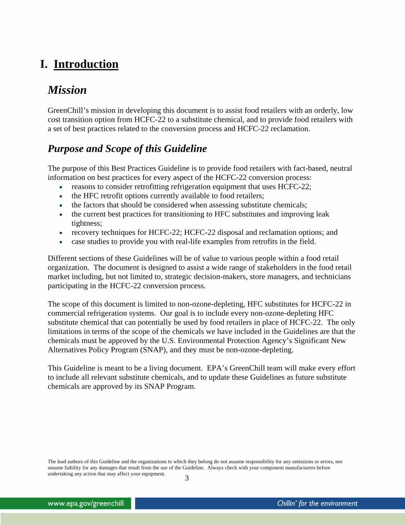
The 2007 Meeting of the Parties to the Montreal Protocol resulted in lower consumption and production caps for the United States (see the following chart), which will reduce the available supply of HCFC-22 starting in 2010.
U.S. EPA HCFC-22 Step Down Plan with 2007 Consumption & Production Cap Revisions
HCFC-22 Supply and Demand You also see on the charts above that the United States has an annual cap on the production and consumption of HCFCs that it must meet under the Montreal Protocol. As of 2010, the amount of HCFCs the United States is allowed to consume and produce must be reduced by 75% from its cap (the cap is the level of HCFC use in 1989). By the year 2015, the supply of HCFCs will be reduced by 90%.
0
2
4
6
8
10
12
14
16
18
2002 2004 2006 2008 2010 2012 2014 2016 2018 2020
Year
OD
P w
td (K
T)
Montreal Protocol CAP R22 Allocation CAP Current Revised Montreal Protocol Cap
15.24 ODP Wtd KT is the original base level agreed upon in the Montreal Protocol
2004 35% reduction in ODP mandated by Montreal Protocol- achieved in the US through Phaseout of 141b
HCFC22 allocation CAP implemented in 2004 by EPA to avoid exceeding Montreal Protocol CAP
2010 65% reduction in ODP- original agreement; New schedule is 75% reduction
2015 90% reduction2020 99.5% reduction
HCFC-22 users need to be aware of the upcoming HCFC-22 constraint due to the reduction in total USA rights to consume ozone-depleting products. To offset these concerns, there are several options to move away from HCFC-22 use. Included in these options are opportunities to repair old leaky equipment, reclaim used HCFC-22, retrofit to new HFC products, and replace old equipment. These Guidelines specifically address retrofitting to new HFC products and the reclamation of used HCFC-22.
The lead authors of this Guideline and the organizations to which they belong do not assume responsibility for any omissions or errors, nor assume liability for any damages that result from the use of the Guideline. Always check with your component manufacturers before undertaking any action that may affect your equipment.
6

EPA has estimated the demand for HCFC-22 after the phaseout in 2010. The table below shows the projected HCFC-22 demand (including that used in blends) for servicing equipment in 2010, 2015, and 2020. These estimates were developed based on EPA’s Vintaging Model, which takes into account recent industry input (EPA, June 2008). It is projected that in 2010, approximately 62,500 metric tons of HCFC-22 will be required to service AC and refrigeration equipment, of which the majority—41,700 metric tons (67%)—will be used to service AC systems. In 2015, servicing demand is projected to reach approximately 38,700 metric tons of HCFC-22 for AC and refrigeration equipment, and in 2020, the projected demand quantity declines to 18,200 metric tons.
Projected HCFC-22 Servicing Demand (2010-2020) (Metric Tons)
The lead authors of this Guideline and the organizations to which they belong do not assume responsibility for any omissions or errors, nor assume liability for any damages that result from the use of the Guideline. Always check with your component manufacturers before undertaking any action that may affect your equipment.
7
Equipment Type 2010 2015 2020 Total AC 41,700 25,900 11,300 Total Refrigeration 20,800 12,800 7,000 Overall Total 62,500 38,800 18,200
HCFC consumption is capped as described below. Both the 2015 and 2020 projections of servicing demand exceed the U.S. consumption cap for virgin HCFCs for these years. However, a portion of the servicing needs are expected to be met by using recovered and reclaimed refrigerant, thus decreasing the need for virgin HCFC-22. HCFC users should be planning for this transition in order to avoid costly investments and uncertainty in the future availability of the chemical.
HCFC Consumption Phaseout Targets Under the Montreal Protocol Date Consumption Cap Quantity Expressed in R-
22 Metric Tons
Jan 1, 1996 Consumption freeze capped at 2.8% of the 1989 ODP-weighted CFC consumption plus 100% of the 1989 ODP-weighted HCFC consumption
277,091 metric tons
Jan 1, 2004 35% reduction of the cap 180,109 metric tons Jan 1, 2010 75% reduction of the cap 69,270 metric tons Jan 1, 2015 90% reduction of the cap 27,709 metric tons Jan 1, 2020 99.5% reduction of the cap 0 metric tons
Jan 1, 2030 100% reduction of the cap 0 metric tons
III. HFC Refrigerant Retrofits
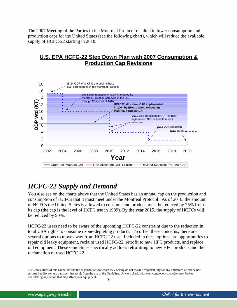
HFC Retrofit Options
There are two main approaches to retrofitting supermarkets from HCFC-22 to HFCs:
1. Replacing only the refrigerant with minimal changes or adjustments to the refrigeration system.
2. Using new mechanical systems, which may include compressors, condensers and refrigerated cases, along with a change to an HFC refrigerant.
There are advantages and disadvantages to each approach, as explained in the following section. Regardless of the retrofit approach chosen, a retrofit should always include leak tightness improvements to the refrigeration system. Emissions of refrigerants are what cause problems in the atmosphere. Although HFC substitute chemicals do not deplete the ozone layer, they remain very potent greenhouse gases (as is HCFC-22). To prevent exchanging one environmental problem (ozone depletion) for another (global warming), it is very important that food retailers use the retrofit conversion process as an opportunity to prevent refrigerant emissions and tighten up the leak rates of their systems. This makes sense for the environment, but it also makes sense economically. It costs money to replace refrigerant lost to leaks. HFC Refrigerant only Retrofit The major advantages of a refrigerant only retrofit are the possibility of minimal retrofit costs and minimal disruption to store operations while moving to a non-ozone-depleting fluid. The type of installed system and the chosen HFC or HFC/Hydrocarbon blend will determine the amount of mechanical, lubricant and control changes required to accomplish the retrofit. The lead authors of this Guideline and the organizations to which they belong do not assume responsibility for any omissions or errors, nor assume liability for any damages that result from the use of the Guideline. Always check with your component manufacturers before undertaking any action that may affect your equipment.
8

Selecting a refrigerant with mass flows within 30% of those of HCFC-22 may allow for the use of the existing thermal expansion valves. Retrofit refrigerants with low side operating pressures close to those of HCFC-22 will assist in proper thermal expansion valve operation. Another advantage of retrofitting the existing equipment to an HFC is the benefit of lower discharge temperatures inherent to some of the R-400 series blends and R-507A as compared to HCFC-22. If the discharge temperature is sufficiently low, issues associated with desuperheaters, liquid injection and oil coolers are eliminated, which may lead to reduced maintenance costs. A side benefit of deactivating these devices may be a gain in system capacity and efficiency. If the existing system utilizes heat recovery to heat air or water, then too low of a discharge temperature may require changes to these secondary systems. A retrofit to an HFC refrigerant moves the supermarket’s refrigeration system to zero ozone depletion. HFCs have a solid track record of performance and reliability since their introduction. Mechanics have been working with refrigerant blends for more than a decade, and the handling of these fluids has become commonplace. One major disadvantage of retrofitting HCFC-22 equipment to some of the current commercial HFC options is the potential efficiency decrease relative to HCFC-22. As noted above, reduced discharge temperatures, particularly in low temperature systems, with some of the available substitutes can lead to efficiencies which match HCFC-22. The decrease in efficiency can be aggravated or alleviated by system design, geographic location and refrigerant chosen. Certain blends benefit from sub-cooling more than others, and this technique can bring some of the HFC selections very close to performing like HCFC-22. A cautious approach should be taken when introducing a new refrigerant to an older system, and in addition to the criteria listed here, an evaluation of the resultant operating pressures is in order. If the choice is made to continue the use of mineral-based lubricants, an evaluation of the system’s oil separating technology should be made. The mineral oil compatible HFC/Hydrocarbon blends may be ineffective if the oil carryover ratio to the low side of the system is excessive. Systems without oil separators should not consider a non-miscible refrigerant/oil approach. An evaluation of the gasket materials used in an older installation is warranted, as shrinking may occur after the removal of the HCFC-22. Valve and equipment suppliers are aware of this situation and can supply suitable replacements to be installed during the retrofit. It is strongly recommended that elastomeric seals be replaced regardless of the retrofit path chosen. Selection of the retrofit refrigerant should be made after evaluating the current system’s performance and evaluating the selection criteria listed in this section.
The lead authors of this Guideline and the organizations to which they belong do not assume responsibility for any omissions or errors, nor assume liability for any damages that result from the use of the Guideline. Always check with your component manufacturers before undertaking any action that may affect your equipment.
9

Even when choosing a refrigerant-only retrofit, the retrofit process is a good opportunity to examine your refrigeration system and focus attention on performance to incur additional benefits by changing seals, repairing leaks, and cleaning the system. Retrofitting with New Mechanicals and HFC Refrigerant Advantages of retrofitting with an HFC refrigerant and new mechanicals include the ability to adopt advances in mechanical design concepts and control strategies while moving to a non-ozone-depleting refrigerant. Food retailers can address existing mechanical shortcomings due to age or store layout, and display case changes can be carried out. High leak rates can be addressed with the removal of the faulty equipment or piping system. New equipment can encompass some or all of the strategies referenced, resulting in an efficient installation that is in compliance with all EPA regulations. Efficient operation of the refrigeration system is a major factor to consider when planning a mechanical and refrigerant retrofit and several approaches can be utilized.
• Improved control strategies such as floating head pressure control, liquid amplification, ambient and mechanical sub-cooling and multiple suction groupings. All four approaches have proven to reduce energy consumption of mechanical refrigeration plants.
• Advances in compressor and motor design as well as improved microprocessor based controllers, variable frequency drives and flow controls have also shown to contribute to energy savings.
Replacing equipment during a retrofit results in a system with known operating characteristics. The relationship of POE lubricants and HFC refrigerants is fully understood by compressor manufacturers and system designers. Oil return problems in DX supermarkets utilizing oil separators and good piping practices with this refrigerant/oil combination appear to be non-existent. POE lubricated HFC systems have good compressor longevity which can be enhanced by good service and maintenance practices. Replacement of equipment during the retrofit also has the advantage of delivering known capacity and performance values. A full evaluation of the supermarket installation can address mechanical deficiencies, and these can be corrected with an equipment upgrade. Disadvantages of equipment changes certainly include higher equipment purchase costs relative to refrigerant only retrofits and potential disruption of store operations. Retrofit cost estimates are difficult to determine, due to the variety of types of installations. Additional indirect costs may occur, depending on whether the supermarket remains in operation during the retrofit process. Display case upgrades and change outs, store piping layout, and the refrigerant selected all have a bearing on costs. The location of the equipment room dictates the difficulty of replacing compressor systems, which affects the overall cost of the retrofit. The lead authors of this Guideline and the organizations to which they belong do not assume responsibility for any omissions or errors, nor assume liability for any damages that result from the use of the Guideline. Always check with your component manufacturers before undertaking any action that may affect your equipment.
10

• On grade outdoor mechanical rooms appear to have the advantage of being retrofitted or completely changed with minimal sales floor or rooftop disruption.
• Distributed systems may offer the opportunity to locate the new equipment closer to the loads, for example on the rooftop, as well as performing electrical hook up and pre-piping with little sales floor interruption until final case tie in.
• If the remodel calls for only back room mechanical changes with no case changes or modifications, then the selection of an HFC with mass flows similar to HCFC-22 will minimize any work on the sales floor.
• If the refrigerant chosen has less capacity than HCFC-22, more compressor displacement can be added during the retrofit.
In summary, purchasing new equipment for a retrofit may be more expensive initially than a refrigerant only retrofit, but it is advantageous long-term in that it matches the mechanical system to the chosen HFC, which may maximize the performance of the mechanical system. It must be noted that some disruption to store operations are unavoidable with this option. Leak Tightness Improvements during Retrofits A refrigerant is harmful to the atmosphere only when it is emitted into the atmosphere. According to EPA estimates based on the Revised Draft Analysis of U.S. Commercial Supermarket Refrigeration Systems (EPA, 2005), a typical supermarket refrigeration system holds a refrigerant charge of about 4000 pounds. The average leak rate for a typical supermarket is about 25% per year. Thus, on average, a supermarket emits approximately 1,000 pounds of refrigerant into the atmosphere annually. Although emissions of an HFC substitute chemical do not deplete the ozone layer, HFCs are very potent greenhouse gases (as is HCFC-22). If nothing is done during a retrofit to repair leaks in a refrigeration system, that system will emit 1000 pounds of a potent greenhouse gas into the atmosphere, instead of 1000 pounds of an ozone-depleting substance, thus simply exchanging one environmental problem (ozone depletion) for another (global warming). To prevent this, it is very important that food retailers use the retrofit conversion process as an opportunity to prevent refrigerant emissions and tighten up the leak rates of their systems. This not only makes sense for the environment, but it also makes sense economically. Leaks cost money, regardless of which refrigerant is used. Factors that Should Be Considered when Assessing Retrofit Options Prior to embarking on a retrofit program, several factors should be considered to assess which substitute chemical is the right choice for a particular store. These factors include cooling capacity, efficiency, mass flow of refrigerant and lubricant compatibility. Other factors to consider are compressor manufacturer’s approval of the various substitute chemicals, estimated retrofit cost, store disruption and the GWP of refrigerant candidates. Capacity
The lead authors of this Guideline and the organizations to which they belong do not assume responsibility for any omissions or errors, nor assume liability for any damages that result from the use of the Guideline. Always check with your component manufacturers before undertaking any action that may affect your equipment.
11

A retrofit can only be deemed successful if the refrigeration plant can maintain case and product temperatures. A survey of the refrigeration system is mandatory to compare the installed condensing unit capacity vs. the case load. Once the available capacity is determined, a survey of the commercially available HFCs using thermodynamic data can be made. Plant operating characteristics, such as design suction and discharge temperatures, as well as available sub-cooling and superheat settings, must be used in the analysis to screen retrofit candidates. Some compressor manufacturers have evaluated retrofit HFCs and may have capacity data as well. Care should be taken in understanding how capacity is defined, as compressor manufacturers normally include the “non-useful” heat picked up in the return line and the return gas temperature is often quoted at 68F. This overstates the capacity. The evaporator capacity will determine whether the case temperature can be met. Obviously, if the installed system requires 100% of the capacity of HCFC-22, then the installation of a fluid with less capacity will lead to elevated case temperatures, particularly on summer design days. Anecdotal information and even field trial data can be misleading indicators for a particular selection; thorough analysis upfront helps to ensure a successful retrofit. Efficiency As in the analysis of capacity referenced above, the coefficient of Performance (COP) of a retrofit fluid can be determined using thermodynamic analysis or published compressor manufacturer’s data for selected fluids. Again, care should be taken in understanding if the COP is truly based on evaporator load. In some cases the current commercial retrofit candidates will be less efficient than HCFC-22. System efficiency may be enhanced by technology upgrades. Mass flow The mass flow of refrigerant in a given system is determined by the installed compressor displacement and the density of the suction vapor entering the compressor at the design conditions. Mass flows that vary greatly from that of HCFC-22 will particularly affect the operation of the thermal expansion devices. Depending on the initial valve selection and the low side operating pressures of the selected refrigerant, the entire valve may require replacement. Refrigerants with high mass flows (relative to HCFC-22) will generally require replacement. Valve manufacturers should be consulted prior to the retrofit to determine the extent of modifications required. Higher mass flows can also lead to greater pressure drop in refrigerant piping. An analysis of the installed piping system with particular attention to suction line piping will identify piping runs which may need to be replaced with larger diameters. While this situation is rare with the use of current retrofit fluids, some instances have been reported. Higher pressure drops can lead to degraded system efficiency. Equipment Change Equipment changes in a given system are determined at three points in a DX system.
The lead authors of this Guideline and the organizations to which they belong do not assume responsibility for any omissions or errors, nor assume liability for any damages that result from the use of the Guideline. Always check with your component manufacturers before undertaking any action that may affect your equipment.
12

1) compressor: the installed compressor capacity and efficiency 2) evaporator: the flow rate required per ton of cooling, evaporator pressure and suction line capacity 3) condenser: the flow rate required for the heat rejected, condensing pressure and liquid line capacity Refrigerants with a balance of properties including: compressor capacity, efficiency, mass flow per ton of cooling, evaporator and condenser pressures, suction and liquid line capacities that vary greatly from that of HCFC-22 could impact the operation of the system. Equipment manufacturers should be consulted prior to the retrofit to determine the extent of modifications required. No refrigerant is a “drop in” for HCFC-22, and equipment owners should evaluate replacement refrigerants before choosing an HCFC-22 replacement refrigerant. Lubricant Compatibility HCFC refrigerants are miscible with mineral-based lubricants, while HFCs utilize synthetic lubricants. The addition of hydrocarbons to HFCs may enhance the ability of some systems to utilize mineral-based lubricants. Oil separators and proper piping practices are essential for satisfactory oil return when using a non-miscible combination. Compressor Manufacturer Approval Compressor manufacturers supply and often extend warranties on the most expensive component of the supermarket mechanical system. It is advisable to utilize their experience and testing when selecting a retrofit fluid. Some installed compressors on older mechanical packages may not be suitable or may require modification to utilize HFCs with synthetic lubricants (for example Copeland R22 to R407C guidelines, form no. 95-14 R2, state that compressors prior to 1973 should not be retrofitted with new refrigerants and oil). Global Warming Potential While not a factor in the refrigeration capacity, efficiency or other physical parameters, a selection based on global warming potential can be a prudent environmental choice. Disruption to Store Operations The amount of interruption to store operations during each retrofit should be considered. Time spent emptying and restocking cases (if necessary), potential for lost sales during a retrofit, and interference with customer shopping experiences should be understood during the retrofit planning process. Value/Cost Calculation Total cost of ownership should be considered when choosing a retrofit refrigerant. Total cost of ownership consists of two elements: first cost and future operating costs.
The lead authors of this Guideline and the organizations to which they belong do not assume responsibility for any omissions or errors, nor assume liability for any damages that result from the use of the Guideline. Always check with your component manufacturers before undertaking any action that may affect your equipment.
13

First cost: • Labor
o Engineering o Installation & follow up for leak checks
• Materials o Refrigerant o Charge size (lbs.) o Seals o Oil changes if necessary o Expansion valves if necessary o Line changes if necessary o Ball valves if necessary
Future Operating Costs discounted to present value: e.g., some supermarkets use 8% discount rate for an 8 year period.
• Energy Consumption for medium temperature refrigeration • Energy Consumption for low temperature refrigeration • Compressor life • Service refrigerant
Refrigerant Charge Size (lbs) x Leak Rate (%/yr) x Refrigerant Cost ($/lb) = Service Refrigerant ($/yr)
• Service labor Lab Tests on Retrofit Refrigerants: Performance Data vs. HCFC-22 The following laboratory data have been provided by GreenChill’s current retrofit chemical manufacturing partners: Honeywell, DuPont, Ineos Fluor, and Arkema. Because each company uses different equipment and methodologies to conduct its laboratory tests and analyses, it was impossible to do a valid side-by-side comparison of the chemicals. GreenChill does not endorse any of the following chemicals, and EPA has not verified the accuracy of the following information. Please contact the appropriate chemical manufacturer with any questions you may have about the lab data and analyses that are contained in this section of the Guidelines. Please note: all Global Warming Potentials are taken from the IPCC 4th Assessment Report, 2007. In some cases, the numbers are rounded off to the nearest hundred.
The lead authors of this Guideline and the organizations to which they belong do not assume responsibility for any omissions or errors, nor assume liability for any damages that result from the use of the Guideline. Always check with your component manufacturers before undertaking any action that may affect your equipment.
14

Lab Tests on Retrofit Refrigerants: Honeywell Performance Data vs. HCFC-22 Honeywell has evaluated all of the commercially available and ASHRAE listed HFC and HFC/HC refrigerants using thermodynamic, system and calorimeter testing. Below is a partial list of these refrigerants being considered as candidates for retrofitting HCFC-22 systems. The range of capacities and efficiencies for each fluid is the result of the three evaluation tools. The first table is meant as a guide using the operating conditions listed in the table below it. As many supermarkets utilize mechanical sub-cooling, capacity and efficiency values for sub-cooled low temperature liquid are included to demonstrate the effect of this technique on the fluids. It should be noted that the increased sub-cooling load is generally moved to the medium temperature systems and these systems should be evaluated when considering this technique. Honeywell Refrigerant Technical Services is available to discuss your retrofit project using the refrigerants listed here or any fluid under consideration using your operating parameters.
GWP Evap Glide
Comp. Ratio
Diff. Disch.
T
Mass Flow Capacity Efficiency Capacity Efficiency
# °F % °F % % % % %R407A 2100 7.2 112 -56 105 90 to 96 89 to 95 96 to 102 94 to 100 POE TXV adjustment
R407C 1800 7.6 116 -44 92 86 to 92 91 to 97 91 to 97 94 to 100 POE TXV adjustment
R422D 2700 4.8 108 -106 123 76 to 82 83 to 89 86 to 92 93 to 99 POE (MO,AB) No Change
R507A 4000 0.0 94 -106 151 93 to 99 81 to 87 106 to 112 92 to 98 POE Change TXV
R404A 3900 0.8 95 -103 143 91 to 97 82 to 88 103 to 109 92 to 98 POE Change TXV
Low
Te
mpe
ratu
re
Retrofit Issues
Preferred Lubricant (optional)
Equipment Evaluation
Refr.
A
R407A 2100 7.7 107 -29 112 100 to 106 93 to 99 NA NA POE TXV adjustment
R407C 1800 8.4 108 -22 99 96 to 102 94 to 100 NA NA POE TXV adjustment
R422D 2700 4.9 104 -57 129 87 to 93 90 to 96 NA NA POE (MO,AB) No Change
R507A 4000 0.0 97 -57 150 100 to 106 87 to 93 NA NA POE Change TXV
R404A 3900 0.7 97 -56 143 98 to 104 88 to 94 NA NA POE Change TXV
dded Subcooling
PerformanceMain Parameters Standard
Performance
Med
ium
Te
mpe
ratu
re
Parameter Mediun Temperature
Low Temperature
Low Temperature
Added Subcooling
Condensing Temperature 105°F 105°F 105°FDegree of Subcooling at TXV Inlet 10°F 10°F 55°FEvaporation Temperature 20°F -25°F -25°FSuperheat at Evaporator Outlet 10°F 10°F 10°FSuperheat gain in the Suction Line 15°F 40°F 40°FCompressor Isentropic Efficiency 60% 60% 60%Compressor Volumetric Efficiency 100% 100% 100%
Operating Conditions
The lead authors of this Guideline and the organizations to which they belong do not assume responsibility for any omissions or errors, nor assume liability for any damages that result from the use of the Guideline. Always check with your component manufacturers before undertaking any action that may affect your equipment.
15

Laboratory Tests on Retrofit Refrigerants: ISCEON® Performance Data vs. HCFC-22 DuPont has completed extensive compressor calorimeter tests on the leading R-22 replacement refrigerants to help supermarket retailers make educated choices. The table below summarizes the performance of several retrofit refrigerant options relative to R-22. More detail about the actual test results for both Copeland® brand and Carlyle® brand compressors is available to customers upon request.
Potential Alternatives UoM HCFC-22 R-404A R-407C R-422A R-422D Condenser Temp °F 80 105 80 105 80 105 80 105 80 105 Relative Med Temp Capacity (20 °F) 65 F return gas; Sub-cooled liquid 10 °F below average condenser temperature
BTUH 1 1 1.17 1.11 1.01 0.96 1.13 1.08 1.01 0.96
Relative Low Temp Capacity (-25 °F)
BTUH 1 1 1.25 1.17 0.98 0.91 1.24 1.19
65 F return gas; Sub-cooled liquid 10 °F below average condenser temperature for 80 °F condenser conditions; Sub-cooled liquid 15 °F below average condenser temperature for 105 °F condenser conditions
1.06 0.97
Keep TXV Yes No Yes No Evaluation
Keep Line Sets Yes Evaluation Yes Evaluation Evaluation
Relative Med Temp EER (20 °F) 65 F return gas; Sub-cooled liquid 10 °F below average condenser temperature
BTUH/W
1 1 1 0.97 0.97 0.96 0.92 0.94 0.99 1.00
Relative Low Temp EER (-25 °F)
BTUH/W
1 1 1.03 1.03 0.98 0.93 1.06
65 F return gas; Sub-cooled liquid 10 °F below average condenser temperature for 80 °F condenser conditions; Sub-cooled liquid 15 °F below average condenser temperature for 105 °F condenser conditions
1.07 1.04 1.04
Copeland Compressor Retrofit Approval
Yes Yes Yes Yes Yes
UL Listed Yes Yes Yes Yes Yes GWP IPCC
4th1810 3920 1760 3140 2730
Use Mineral Oil Yes No No Yes Yes Med Temp Discharge Temp
°F 186 225 149 177 170 204 144 169 148 172
Low Temp Discharge Temp
°F 230* 230* 201 225 225 230*
192 214 195 218
* Liquid Injection required to maintain 230 °F discharge temperature
The lead authors of this Guideline and the organizations to which they belong do not assume responsibility for any omissions or errors, nor assume liability for any damages that result from the use of the Guideline. Always check with your component manufacturers before undertaking any action that may affect your equipment.
16
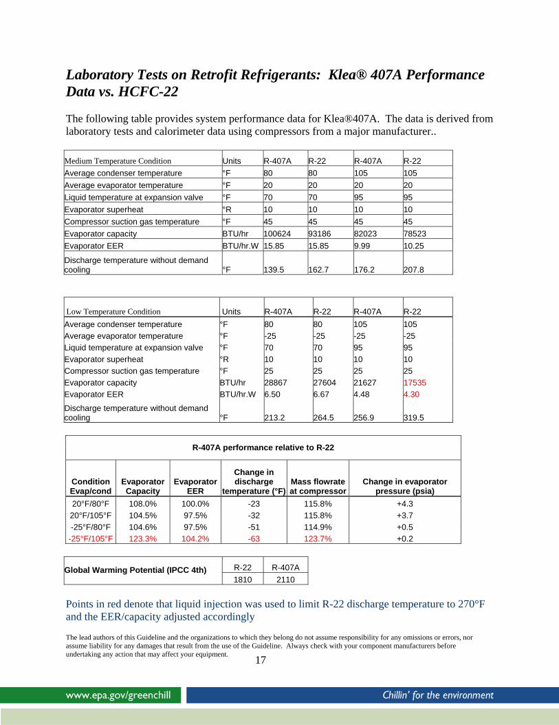
Laboratory Tests on Retrofit Refrigerants: Klea® 407A Performance Data vs. HCFC-22 The following table provides system performance data for Klea®407A. The data is derived from laboratory tests and calorimeter data using compressors from a major manufacturer.. Medium Temperature Condition Units R-407A R-22 R-407A R-22 Average condenser temperature °F 80 80 105 105 Average evaporator temperature °F 20 20 20 20 Liquid temperature at expansion valve °F 70 70 95 95 Evaporator superheat °R 10 10 10 10 Compressor suction gas temperature °F 45 45 45 45 Evaporator capacity BTU/hr 100624 93186 82023 78523 Evaporator EER BTU/hr.W 15.85 15.85 9.99 10.25
Discharge temperature without demand cooling °F 139.5 162.7 176.2 207.8
Low Temperature Condition Units R-407A R-22 R-407A R-22 Average condenser temperature °F 80 80 105 105 Average evaporator temperature °F -25 -25 -25 -25 Liquid temperature at expansion valve °F 70 70 95 95 Evaporator superheat °R 10 10 10 10 Compressor suction gas temperature °F 25 25 25 25 Evaporator capacity BTU/hr 28867 27604 21627 17535 Evaporator EER BTU/hr.W 6.50 6.67 4.48 4.30
Discharge temperature without demand cooling °F 213.2 264.5 256.9 319.5
R-407A performance relative to R-22
Evaporator Capacity
Evaporator EER
Change in discharge
temperature (°F)Mass flowrate at compressor
Change in evaporator pressure (psia)
Condition Evap/cond 20°F/80°F 108.0% 100.0% -23 115.8% +4.3
20°F/105°F 104.5% 97.5% -32 115.8% +3.7 -25°F/80°F 104.6% 97.5% -51 114.9% +0.5
-25°F/105°F 123.3% 104.2% -63 123.7% +0.2
R-22 R-407A Global Warming Potential (IPCC 4th) 1810 2110
Points in red denote that liquid injection was used to limit R-22 discharge temperature to 270°F and the EER/capacity adjusted accordingly
The lead authors of this Guideline and the organizations to which they belong do not assume responsibility for any omissions or errors, nor assume liability for any damages that result from the use of the Guideline. Always check with your component manufacturers before undertaking any action that may affect your equipment.
17
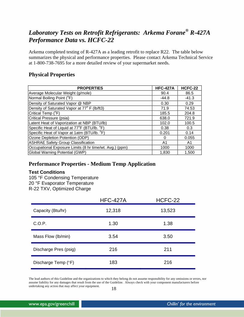
Laboratory Tests on Retrofit Refrigerants: Arkema Forane® R-427A Performance Data vs. HCFC-22 Arkema completed testing of R-427A as a leading retrofit to replace R22. The table below summarizes the physical and performance properties. Please contact Arkema Technical Service at 1-800-738-7695 for a more detailed review of your supermarket needs. Physical Properties
PROPERTIES HFC-427A HCFC-22
Average Molecular Weight (g/mole) 90.4 86.5 Normal Boiling Point (oF) -44.8 -41.3 Density of Saturated Vapor @ NBP 0.30 0.29 Density of Saturated Vapor at 77o F (lb/ft3) 71.9 74.53 Critical Temp (oF) 185.5 204.8 Critical Pressure (psia) 638.0 721.9 Latent Heat of Vaporization at NBP (BTU/lb) 102.0 100.5 Specific Heat of Liquid at 77oF (BTU/lb. oF) 0.38 0.3 Specific Heat of Vapor at 1atm (BTU/lb. oF) 0.201 0.14 Ozone Depletion Potention (ODP) 0 0.055 ASHRAE Safety Group Classification A1 A1 Occupational Exposure Limits (8 hr time/wt. Avg.) (ppm) 1000 1000 Global Warning Potential (GWP) 1,830 1,500 Performance Properties - Medium Temp Application Test Conditions 105 °F Condensing Temperature 20 °F Evaporator Temperature R-22 TXV, Optimized Charge
HFC-427A HCFC-22
12,318 13,523 Capacity (Btu/hr)
1.30 1.38 C.O.P.
3.54 3.50 Mass Flow (lb/min)
216 211 Discharge Pres (psig)
183 216 Discharge Temp (°F)
The lead authors of this Guideline and the organizations to which they belong do not assume responsibility for any omissions or errors, nor assume liability for any damages that result from the use of the Guideline. Always check with your component manufacturers before undertaking any action that may affect your equipment.
18

IV. Best Practices for Transitioning to HFC Substitute
Chemicals Conversion Guidelines for HFC Substitute Chemicals The following section is a list of conversion procedures that a typical retailer will likely undertake to retrofit equipment that was designed to use HCFC-22, along with general guidance on a typical conversion process. There are retrofit checklists that are specific to each HFC substitute refrigerant in Appendix 2.
1. Determine alternative refrigerant to be used. 2. Determine oil type based on refrigerant manufacturer, equipment OEM and contractor
recommendations. 3. Determine if existing elastomer types are suitable for the proposed refrigerant. 4. Ensure all material is on hand before starting the retrofit. 5. Record performance of existing system using the System Datasheet in Appendix 1. 6. Check for any existing leak, and repair before proceeding with the retrofit. 7. If a change of oil type from mineral oil to POE oil is required, complete this step. If no
change of oil is required, skip to step 8. a. To change to POE oil, first isolate the refrigerant to avoid refrigerant losses
during the oil flush. Pull a vacuum on the system to minimize the amount of refrigerant dissolved in the oil.
b. Drain oil from the system into suitable containers, paying particular attention to the compressor sump, suction line accumulator, oil separator, long runs of piping and any low spots. Measure the amount of oil removed. Dispose of oil through approved channel.
c. Replace filter-drier compatible with POE oil. d. Add the recommended POE oil to the system. e. Evacuate system to 500 microns to remove air and moisture. Hold vacuum to
check for leaks. f. Restart system and check oil level. Adjust oil level if needed. Run system for a
minimum of 24 hours to ensure time for the POE and residual oil to mix. Longer running times will allow more complete mixing and oil return, particularly for larger systems.
g. Check amount of mineral oil content in the system using a refractometer or other commercially available device. If mineral oil content is above the refrigerant manufacturer’s recommended level, repeat step 7.
8. Remove refrigerant from system a. Use an approved recovery machine and recovery cylinders. b. Do not vent refrigerant to atmosphere.
The lead authors of this Guideline and the organizations to which they belong do not assume responsibility for any omissions or errors, nor assume liability for any damages that result from the use of the Guideline. Always check with your component manufacturers before undertaking any action that may affect your equipment.
19

c. Target vacuum level is 15 inches HG. The lower the vacuum level achieved the lower the refrigerant emission when the system is opened and the maximum amount of potentially valuable refrigerant is recovered.
d. Weigh amount of refrigerant recovered. 9. Break the vacuum. 10. Replace equipment as required for new refrigerant and as an opportunity to reduce the
potential for leaks in subsequent operation. a. Replace filter/drier, compatible with new refrigerant. b. Replace TXVs if it has been determined necessary in the initial system selection
process. c. Replace any seal on a joint that was opened. Replace all seals on the rack system.
This will reduce the likelihood of a leak developing even on joints that would not normally be broken as part of a retrofit.
d. Replace old ball valves and repair/replace solenoid valves as necessary, as these are sources of leaks.
e. If original oil type is to be used (step 7 was omitted), check condition of mineral oil and replace if needed.
11. Reset the pressure controls and other equipment as required for the new refrigerant. 12. Pull a vacuum on the system.
a. Target is 500 microns. b. Hold vacuum and check for leaks.
13. Charge system with new refrigerant. a. Charge level will be based on refrigerant manufacturer’s recommendation. b. For blend refrigerants in the ASHRAE 400 series, remove liquid from the
cylinder to ensure correct composition. Ensure liquid is vaporized before reaching the compressor to avoid equipment damage.
14. Check system for any refrigerant leak. a. Check low pressure side of system with compressor off, as the higher vapor
pressure will enhance leak detection. 15. Adjust TXV setting as needed for new refrigerant.
a. For ASHRAE 400 series refrigerants, there will be temperature glide in the condenser and evaporator, i.e. a difference in dew point and bubble point for a given pressure. Consult refrigerant manufacturer for correct dew point / bubble point information.
b. When calculating sub-cooling, use the bubble point as the reference temperature. c. When calculating superheat, use dew point as the reference temperature.
16. Monitor oil level in compressor. a. Check oil level in system and adjust as needed. b. If oil return is not adequate or if oil level is unstable, refer to specific guidelines
from the refrigerant manufacturer for corrective action. 17. Properly label the system with refrigerant and lubricant type and charge.
The lead authors of this Guideline and the organizations to which they belong do not assume responsibility for any omissions or errors, nor assume liability for any damages that result from the use of the Guideline. Always check with your component manufacturers before undertaking any action that may affect your equipment.
20

Material Compatibility Generally, the same seal materials can be used in HCFC-22 and HFC service, but there are exceptions, as the swelling characteristics in HCFCs are different than in HFCs. Viton® does not perform well with R134a, a base component of some of the HFC blends. Different grades of the same material can behave differently. The type of lubricant can also affect material choice. The refrigerant and equipment manufacturers should be consulted to confirm material suitability. Older systems manufactured before the development of HFCs in the early 1990s may have compatibility issues. Differences in Retrofit Procedures for Substitute Chemicals The following chart shows some potential differences in the HCFC-22 conversion process for all SNAP approved, non HCFC-22 containing retrofit chemicals. This is a general guide, and the procedures and requirements for your specific system may vary, so please check with equipment manufacturers and refrigerant manufacturers. There is a detailed, step-by-step conversion checklist for each specific chemical in Appendix 2.
Step R404A R407A R407C R422D R427A
Change oil to POE
Y Y Y N* N*
Flush with POE oil again until residual mineral oil is below recommended level
Y Y Y N* N*
Change TXVs Normally yes
Normally no Normally no
Normally no Normally no
Change seals Y Y Y Y Y Change Powerhead
Y N N N N
Significant Equipment changes due to mass flow and pressure drop
Y N N N N
*A change to POE oil may not required for R422D and R427A if the system has an oil separator and the oil circulation rate is acceptable; if the system does not have an oil separator, the oil must be changed to POE.
The lead authors of this Guideline and the organizations to which they belong do not assume responsibility for any omissions or errors, nor assume liability for any damages that result from the use of the Guideline. Always check with your component manufacturers before undertaking any action that may affect your equipment.
21

V. Best Practices - HCFC-22 End of Life End of Life Options for Refrigerants EPA’s GreenChill Partnership recommends that HCFC-22 be recovered and reclaimed whenever possible. It is a valuable resource, and it will likely become more valuable as the HCFC-22 Phaseout goes into effect in 2010. The following section of the Guidelines gives definitions for the end-of-life options for HCFC-22 and best practices for recovery and reclamation. Recover To “recover” refrigerant, refrigerant in any condition is removed from a system and stored in properly rated recovery cylinders without necessarily testing or processing it in any way. Recycle Refrigerant is extracted from a system and cleaned for reuse without meeting all of the requirements for reclamation. In general, recycled refrigerant is refrigerant that is cleaned using oil separation and single or multiple passes through devices, such as replaceable core filter-driers, which reduce moisture, acidity, and particulate matter. Recycled refrigerant can be stored and used by the same equipment owner. It cannot, however, be sold for use or used in a different equipment owner’s facility. Reclaim Reclamation is the re-processing and upgrading of a recovered refrigerant, through such mechanisms as filtering, drying, distillation and chemical treatment, in order to restore the substance to a specified standard of performance. To be properly reclaimed, used refrigerant must be reprocessed to at least the purity level specified in Appendix A to 40 CFR Part 82, Subpart F, which can be accessed at http://ecfr.gpoaccess.gov/cgi/t/text/text-idx?c=ecfr&sid=ac3317f38276508450ff8759bed79ded&rgn=div9&view=text&node=40:17.0.1.1.2.6.1.12.20&idno=40. Appendix A to 40 CFR Part 82, Subpart F is based on ARI Standard 700, "Specifications for Fluorocarbon and Other Refrigerants.” Some reclaimers offer refrigerant “banking” as a service option. With a banking service, equipment owners ship recovered refrigerant to the reclaimer who then typically restores the refrigerant to ARI Standard 700 condition. The reclaimer then packages and holds the reclaimed refrigerant in storage for the equipment owner until the equipment owner releases material from the “bank.” The reclaimer would charge for processing, packaging and storing the refrigerant. See http://www.epa.gov/ozone/title6/608/reclamation/reclist.html for a list of EPA Certified Refrigerant Reclaimers. Check with reclaimers to verify their service area, capability for processing recovered refrigerant to ARI Standard 700, capability for destruction of contaminated refrigerant, and service options such as banking.
The lead authors of this Guideline and the organizations to which they belong do not assume responsibility for any omissions or errors, nor assume liability for any damages that result from the use of the Guideline. Always check with your component manufacturers before undertaking any action that may affect your equipment.
22
Destroy

Refrigerant that cannot be reclaimed back to ARI 700-1995 standard purity must be destroyed. In this case, the reclamation service provider will most likely incinerate the refrigerant in an EPA-approved facility. Be aware that not all reclaimers have the technology to handle all contaminated or mixed refrigerants. Check with reclamation service providers to verify that they are equipped to dispose of refrigerant in an environmentally acceptable manner with required permits (e.g., an incinerator equipped to decompose refrigerant into CO2 and acid gases; acid gases are then removed from the vent stream by scrubbers before the vent stream is released to the atmosphere). Reclamation and Destruction Costs Before entering into any agreement with a reclamation service provider, the equipment owner should make sure he or she understands all of the costs involved. There may be separate charges for identifying the material, transporting it, and reclaiming or destroying it. If the equipment owner is responsible for shipping the tank, make sure that the reclamation service provider explains how to comply with any applicable U.S. Department of Transportation (DOT), state, and local requirements relating to shipping.
Best Practices – Recovery
Before a refrigerant can be reclaimed, it must be recovered. The following is a list of best practice recovery techniques. Proper handling and recovery will avoid “disposal” fees for mixed refrigerant.
• Do not mix refrigerants of different ASHRAE numbers in a recovery cylinder. Do NOT mix refrigerants either in the system or in a recovery cylinder. Doing so can result in contaminated refrigerant which may have to be destroyed.
• Tag the recovery cylinder by listing refrigerant “type.” Tag cylinders properly. • Do not overfill recovery cylinders Weigh cylinder once refrigerant is recovered from
system; check versus maximum fill weights. • Need 10-15 inches Hg (50-67 kPa) vacuum to remove charge. The recommended level of
evacuation for typical commercial refrigeration systems is 15 inches of mercury vacuum, relative to standard atmospheric pressure of 29.9 inches Hg.
• Remove blends from cylinder as liquid when charging equipment. • Recover existing refrigerant charge from system into proper pressure rated recovery
cylinders (see the table below). • Identify the refrigerant that was used to charge the system by placing a retrofit label or
other identity tag on the system. • Return recovered refrigerant to your refrigerant wholesaler or reclaim service provider.
The lead authors of this Guideline and the organizations to which they belong do not assume responsibility for any omissions or errors, nor assume liability for any damages that result from the use of the Guideline. Always check with your component manufacturers before undertaking any action that may affect your equipment.
23
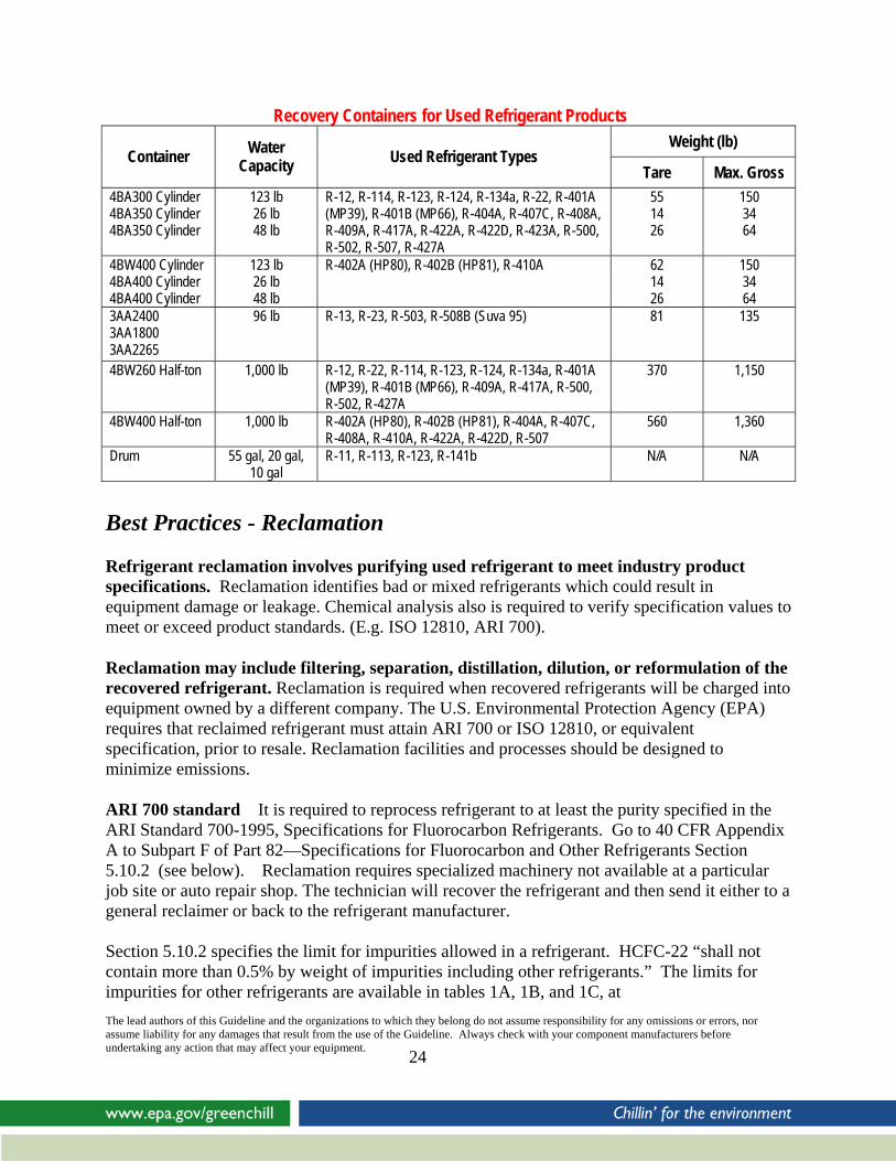
Recovery Containers for Used Refrigerant Products Weight (lb)
Container Water Capacity Used Refrigerant Types
Tare Max. Gross 4BA300 Cylinder 4BA350 Cylinder 4BA350 Cylinder
123 lb 26 lb 48 lb
R-12, R-114, R-123, R-124, R-134a, R-22, R-401A (MP39), R-401B (MP66), R-404A, R-407C, R-408A, R-409A, R-417A, R-422A, R-422D, R-423A, R-500, R-502, R-507, R-427A
55 14 26
150 34 64
4BW400 Cylinder
The lead authors of this Guideline and the organizations to which they belong do not assume responsibility for any omissions or errors, nor assume liability for any damages that result from the use of the Guideline. Always check with your component manufacturers before undertaking any action that may affect your equipment.
24
4BA400 Cylinder 4BA400 Cylinder
123 lb 26 lb 48 lb
R-402A (HP80), R-402B (HP81), R-410A 62 14 26
150 34 64
3AA2400 3AA1800 3AA2265
96 lb R-13, R-23, R-503, R-508B (Suva 95) 81 135
4BW260 Half-ton 1,000 lb R-12, R-22, R-114, R-123, R-124, R-134a, R-401A (MP39), R-401B (MP66), R-409A, R-417A, R-500, R-502, R-427A
370 1,150
4BW400 Half-ton 1,000 lb R-402A (HP80), R-402B (HP81), R-404A, R-407C, R-408A, R-410A, R-422A, R-422D, R-507
560 1,360
Drum 55 gal, 20 gal, 10 gal
R-11, R-113, R-123, R-141b N/A N/A
Best Practices - Reclamation Refrigerant reclamation involves purifying used refrigerant to meet industry product specifications. Reclamation identifies bad or mixed refrigerants which could result in equipment damage or leakage. Chemical analysis also is required to verify specification values to meet or exceed product standards. (E.g. ISO 12810, ARI 700).
Reclamation may include filtering, separation, distillation, dilution, or reformulation of the recovered refrigerant. Reclamation is required when recovered refrigerants will be charged into equipment owned by a different company. The U.S. Environmental Protection Agency (EPA) requires that reclaimed refrigerant must attain ARI 700 or ISO 12810, or equivalent specification, prior to resale. Reclamation facilities and processes should be designed to minimize emissions.
ARI 700 standard It is required to reprocess refrigerant to at least the purity specified in the ARI Standard 700-1995, Specifications for Fluorocarbon Refrigerants. Go to 40 CFR Appendix A to Subpart F of Part 82—Specifications for Fluorocarbon and Other Refrigerants Section 5.10.2 (see below). Reclamation requires specialized machinery not available at a particular job site or auto repair shop. The technician will recover the refrigerant and then send it either to a general reclaimer or back to the refrigerant manufacturer. Section 5.10.2 specifies the limit for impurities allowed in a refrigerant. HCFC-22 “shall not contain more than 0.5% by weight of impurities including other refrigerants.” The limits for impurities for other refrigerants are available in tables 1A, 1B, and 1C, at

http://ecfr.gpoaccess.gov/cgi/t/text/text-idx?c=ecfr&sid=ac3317f38276508450ff8759bed79ded&rgn=div9&view=text&node=40:17.0.1.1.2.6.1.12.20&idno=40. Specific Recovery, Recycling and Reclamation options and methods depend on the application and refrigeration equipment size. For large refrigeration equipment, used refrigerant can be recovered by an HVAC professional and either reclaimed onsite for reuse or shipped to a reclamation facility. Regardless of which method is used, all personnel must be properly trained to handle refrigerants.
Safety Information
CFC, HCFC and HFC refrigerants are safe when handled properly. However, any refrigerant can cause injury or even death when mishandled. Please review the following guidelines before using any refrigerant. • Do not work in areas with high concentrations of refrigerant vapors. Always maintain adequate ventilation in the work area. Do not breathe vapors. Do not breathe lubricant mists from leaking systems. Ventilate the area well after any leak, before attempting to repair equipment. • Do not use handheld leak detectors to check for breathable air. These detectors are not designed to determine if the air is safe to breathe. Use oxygen monitors to ensure adequate oxygen is available to sustain life. • Do not use flames or torches to search for leaks. Do not use flames in high concentrations of refrigerant. Open flames release large quantities of acidic compounds in the presence of all refrigerants and these compounds can be hazardous. Do not use torches as leak detectors. Old halide torches detect chlorine, which may not be present with new refrigerants. Use an electronic leak detector designed to find the refrigerants you are using. If you detect a visible change in the size or color of a flame when using torches to repair equipment, stop work immediately and leave the area. Ventilate the work area well, and stop any refrigerant leaks before resuming work. These flame effects may be an indication of very high refrigerant concentrations, and continuing to work without adequate ventilation may result in injury or death. Note: Any refrigerant can be hazardous if used improperly. Hazards include liquid or vapor under pressure, and frostbite from the escaping liquid. Overexposure to high concentrations of vapor can cause asphyxiation and cardiac arrest. Please read all safety information before handling any refrigerant.
Safe Handling Practices for disposable and returnable cylinders: The lead authors of this Guideline and the organizations to which they belong do not assume responsibility for any omissions or errors, nor assume liability for any damages that result from the use of the Guideline. Always check with your component manufacturers before undertaking any action that may affect your equipment.
25

• Ensure valve is closed. • Ensure cylinder remains in disposable carton when transporting. • Dispose of disposable cylinders properly – check local requirements for disposal
regulations. Pull vacuum on cylinders to recover refrigerant heel prior to cylinder disposal.
• Return empty cylinders using DOT guidelines for proper transporting.
Filling Recovery Containers When loading used refrigerant into recovery containers, particular care should be exercised with regard to the following areas:
- Container Pressure Recover existing refrigerant charge from system into proper pressure rated recovery cylinders. Do NOT put a higher pressure refrigerant into a lower pressure recovery cylinder (e.g., R-410A requires a 400 psig rated recovery cylinder).
- Container Integrity Prior to filling, inspect the recovery container and valve for signs of damage such as dents or corrosion. Do NOT fill a damaged recovery container.
- Test Date Recovery cylinders and half-ton tanks should not be filled if the present date is more than 5 years past the test date that is stamped on the unit. The test date, which will look similar to the example below, is stamped on the shoulder of the cylinder or the collar of the half-ton tank.
AO 12 04
37 This designation indicates that the unit was retested in December 2004 by retester number AO37. If a recovery container is out of date, it must not be filled. Return it promptly for retesting. Containers filled prior to 5 years from test date may be shipped full to the recovery/evacuation facility.
- Liquid Overfilling of Cylinders
Liquefied used refrigerant will expand when it is exposed to high temperatures. If the container is overfilled, the thermal expansion of the liquid could rupture or bulge the container. The maximum gross weight (total weight of the container and its contents) MUST NOT be exceeded.
The lead authors of this Guideline and the organizations to which they belong do not assume responsibility for any omissions or errors, nor assume liability for any damages that result from the use of the Guideline. Always check with your component manufacturers before undertaking any action that may affect your equipment.
26

- Vapor Overpressuring: Recovery Half-Tons and Cylinders
When a compressor is used to recover refrigerant, the pressure of the recovery half-ton or cylinder must be monitored closely. The maximum container pressure should not exceed the container service pressure during the filling operation.
Note: Only use designated recovery cylinders for used refrigerant.
These GreenChill partners offer Refrigerant Reclamation Services through their wholesale distributors. For more information, contact:
i. Arkema – (800) 245-5858
ii. DuPont – (800) 235-7882
iii. Honeywell – (800) 631-8138
iv. Ineos Fluor – (800) 424-5532
The lead authors of this Guideline and the organizations to which they belong do not assume responsibility for any omissions or errors, nor assume liability for any damages that result from the use of the Guideline. Always check with your component manufacturers before undertaking any action that may affect your equipment.
27

VI. Case Studies for Typical Low and Medium Temperature Conversions
Case History Profiles 1-4: R-427A Case 1 Case 2 Case 3 Case 4 Supermarket owner
Sherm’s Thunderbird, Oregon
Geant Casino, France
Tutt OK supermarket, Italy
Fiesta Food Warehouse, Fontana, CA
Compressor models
Copeland 4DB2200, 4DC2200, 4Ds2200, 6DT3000, 4TD2200
5 Copeland, D6DJ3400AWM/D
Med Temp - 3 Copeland Low Temp – 2 Copeland
12 Copeland
Compressor capacity loading Before retrofit, After retrofit
N/A N/A N/A N/A
Original refrigerant
HCFC-22 HCFC-22 HCFC-22 HCFC-22
Retrofit Refrigerant
HFC-427A HFC-427A HFC-427A HFC-427A
Retrofit Lubricant POE Alkyl Benzene POE Alkyl Benzene Change Date: 6/2008 4/2007 2004 2008 TXV’s changed No No No No Seals Changed Not initially No No No Energy Use Comparison
7% reduction 5% less power consumption Comparable to HCFC-22
N/A
Comments For comparable suction temperature, the discharge temp is over 10 °C below with R-427A
Oil return is good despite a high residual mineral oil level (15% medium temp unit and 5% low temp unit)
Discharge temperatures are lower and the compressors are running cooler
Supermarket Contacts
Arkema 800-738-7695
Arkema 800-738-7695
Arkema 800-738-7695
Arkema 800-738-7695

Case History Profiles 5-10: R-422D Case 5 Case 6 Case 7 Case 8 Case 9 Case 10 Supermarket owner
Pathmark, Massapequa, NY
National Retailer – Houston TX
Northeast Retailer, Quincy MA
Northeast Retailer Latrobe, PA
National Retailer, Long Beach, CA
Midwest Retailer
Compressor models
Copeland, 3DB3-0750, 3DB3A-075E, 3DS3-1000, 3DS3A-100E, 3DB3-1000, 3DS-1500, 3DB-1000, 3DB3R12MO
Caryle 06CC228, 06CC337, 06CC550, 06CC665, 06CC675, 06DR228, 06DM337, 06EM450, 06EM475, 06DR724
Copeland 4DH3-250L, 3DS3A-150L, 3DP3-100L
Copeland 4DL-150E, 4DT-220E, 4DT-2200
Copeland Carlyle
Copeland 06DM-316, 06DR-228, 06DM-337. 06DM-316, 06DR-228, 06DM-337, 06DR-820. 06DM-337, 06ER-175, 06ER-337. 4DT3-220E-TSK, 4DL3-150E-TFD
Compressor capacity loading Before retrofit, after retrofit
N/A N/A N/A 95%, 334,000 BTUH 387,000 BTUH
N/A 0.92, 0.83, 0.92, 0.9, 0.9, 0.66, 0.83
Original refrigerant
HCFC-22 HCFC-22 HCFC-22 HCFC-22 HCFC-22 HCFC-22
Retrofit Refrigerant
R-422D R-422D R-422D R-422D R-422D R-422D
Retrofit Lubricant
Mineral Oil Mineral Oil Mineral Oil Mineral Oil Alkyl Benzene
Mineral Oil
Change Date: 2/27/2007 8/14/2006 8/20/2006 10/9/2007 10/23/08 TXV’s changed No No No No No No Seals Changed Yes Yes Yes Yes Yes Yes Energy Use Comparison
N/A Comparable to HCFC-22
Comparable to HCFC-22 – Medium Temp
12% reduction in energy efficiency - low temp
N/A Energy Impact appeared similar based on temps., pressures, (no KWH monitoring was used).
Comments Store was remodeled, confusion about TXV sizing in cases due to new refrigerant
Proceeding with additional systems
Proceeding with confidence with additional systems
No reported leaks after startup. Turned off demand cooling modules
Operating properly
Operating properly, more stores scheduled
Supermarket Contacts
Mike Framarin 201-573-9700
DuPont 302-999-2709
DuPont 302-999-2709
Cliff Timko 412-963-2354
DuPont 302-999-2709
Frank Remsburg 616-791-3426
The lead authors of this Guideline and the organizations to which they belong do not assume responsibility for any omissions or errors, nor assume liability for any damages that result from the use of the Guideline. Always check with your component manufacturers before undertaking any action that may affect your equipment.
29
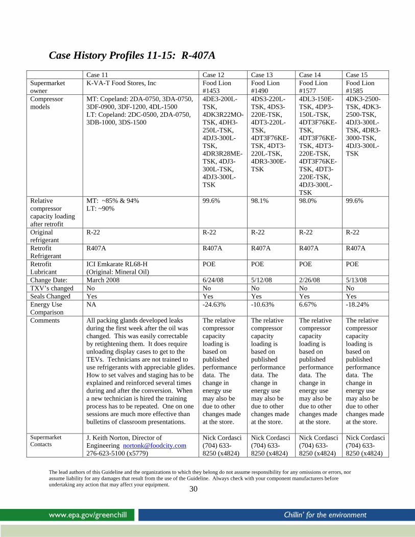
Case History Profiles 11-15: R-407A
Case 11 Case 12 Case 13 Case 14 Case 15 Supermarket owner
K-VA-T Food Stores, Inc
Food Lion #1453
Food Lion #1490
Food Lion #1577
Food Lion #1585
Compressor models
MT: Copeland: 2DA-0750, 3DA-0750, 3DF-0900, 3DF-1200, 4DL-1500 LT: Copeland: 2DC-0500, 2DA-0750, 3DB-1000, 3DS-1500
4DE3-200L-TSK, 4DK3R22MO-TSK, 4DH3-250L-TSK, 4DJ3-300L-TSK, 4DR3R28ME-TSK, 4DJ3-300L-TSK, 4DJ3-300L-TSK
4DS3-220L-TSK, 4DS3-220E-TSK, 4DT3-220L-TSK, 4DT3F76KE-TSK, 4DT3-220L-TSK, 4DR3-300E-TSK
4DL3-150E-TSK, 4DP3-150L-TSK, 4DT3F76KE-TSK, 4DT3F76KE-TSK, 4DT3-220E-TSK, 4DT3F76KE-TSK, 4DT3-220E-TSK, 4DJ3-300L-TSK
4DK3-2500-TSK, 4DK3-2500-TSK, 4DJ3-300L-TSK, 4DR3-3000-TSK, 4DJ3-300L-TSK
Relative compressor capacity loading after retrofit
MT: ~85% & 94% LT: ~90%
99.6% 98.1% 98.0% 99.6%
Original refrigerant
R-22 R-22 R-22 R-22 R-22
Retrofit Refrigerant
R407A R407A R407A R407A R407A
Retrofit Lubricant
ICI Emkarate RL68-H (Original: Mineral Oil)
POE POE POE POE
Change Date: March 2008 6/24/08 5/12/08 2/26/08 5/13/08 TXV’s changed No No No No No Seals Changed Yes Yes Yes Yes Yes Energy Use Comparison
NA -24.63% -10.63% 6.67% -18.24%
Comments All packing glands developed leaks during the first week after the oil was changed. This was easily correctable by retightening them. It does require unloading display cases to get to the TEVs. Technicians are not trained to use refrigerants with appreciable glides. How to set valves and staging has to be explained and reinforced several times during and after the conversion. When a new technician is hired the training process has to be repeated. One on one sessions are much more effective than bulletins of classroom presentations.
The relative compressor capacity loading is based on published performance data. The change in energy use may also be due to other changes made at the store.
The relative compressor capacity loading is based on published performance data. The change in energy use may also be due to other changes made at the store.
The relative compressor capacity loading is based on published performance data. The change in energy use may also be due to other changes made at the store.
The relative compressor capacity loading is based on published performance data. The change in energy use may also be due to other changes made at the store.
Supermarket Contacts
J. Keith Norton, Director of Engineering [email protected]
Nick Cordasci
276-623-5100 (x5779)
Nick Cordasci (704) 633-8250 (x4824)
Nick Cordasci (704) 633-8250 (x4824)
Nick Cordasci (704) 633-8250 (x4824)
(704) 633-8250 (x4824)
The lead authors of this Guideline and the organizations to which they belong do not assume responsibility for any omissions or errors, nor assume liability for any damages that result from the use of the Guideline. Always check with your component manufacturers before undertaking any action that may affect your equipment.
30
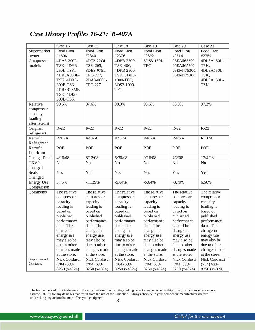
Case History Profiles 16-21: R-407A
Case 16 Case 17 Case 18 Case 19 Case 20 Case 21 Supermarket owner
Food Lion #1608
Food Lion #2340
Food Lion #2376
Food Lion #2392
Food Lion #2514
Food Lion #2759
Compressor models
4DA3-200L-TSK, 4DH3-250L-TSK, 4DR3A300E-TSK, 4DR3-300E-TSK, 4DR3R28ME-TSK, 4DJ3-300L-TSK
4DT3-22OL-TSK-205, 3DB3-075L-TFC-227, 2DA3-060L-TFC-227
4DH3-2500-TSK-406, 4DK3-2500-TSK, 3DB3-1000-TFC, 3OS3-1000-TFC
3DS3-150L-TFC
06EA565300, 06EA565300, 06EM475300, 06EM475300
4DL3A150L-TSK, 4DL3A150L-TSK, 4DL3A150L-TSK
Relative compressor capacity loading after retrofit
99.6% 97.6% 98.0% 96.6% 93.0% 97.2%
Original refrigerant
R-22 R-22 R-22 R-22 R-22 R-22
Retrofit Refrigerant
R407A R407A R407A R407A R407A R407A
Retrofit Lubricant
POE POE POE POE POE POE
Change Date: 4/16/08 8/12/08 6/30/08 9/16/08 4/2/08 12/4/08 TXV’s changed
No No No No No No
Seals Changed
Yes Yes Yes Yes Yes Yes
Energy Use Comparison
3.45% -11.29% -5.64% -5.64% -3.79% 6.56%
Comments The relative compressor capacity loading is based on published performance data. The change in energy use may also be due to other changes made at the store.
The relative compressor capacity loading is based on published performance data. The change in energy use may also be due to other changes made at the store.
The relative compressor capacity loading is based on published performance data. The change in energy use may also be due to other changes made at the store.
The relative compressor capacity loading is based on published performance data. The change in energy use may also be due to other changes made at the store.
The relative compressor capacity loading is based on published performance data. The change in energy use may also be due to other changes made at the store.
The relative compressor capacity loading is based on published performance data. The change in energy use may also be due to other changes made at the store.
Nick Cordasci Nick Cordasci Nick Cordasci Nick Cordasci Nick Cordasci Nick Cordasci Supermarket Contacts (704) 633-
8250 (x4824) (704) 633-8250 (x4824)
(704) 633-8250 (x4824)
(704) 633-8250 (x4824)
(704) 633-8250 (x4824)
(704) 633-8250 (x4824)
The lead authors of this Guideline and the organizations to which they belong do not assume responsibility for any omissions or errors, nor assume liability for any damages that result from the use of the Guideline. Always check with your component manufacturers before undertaking any action that may affect your equipment.
31
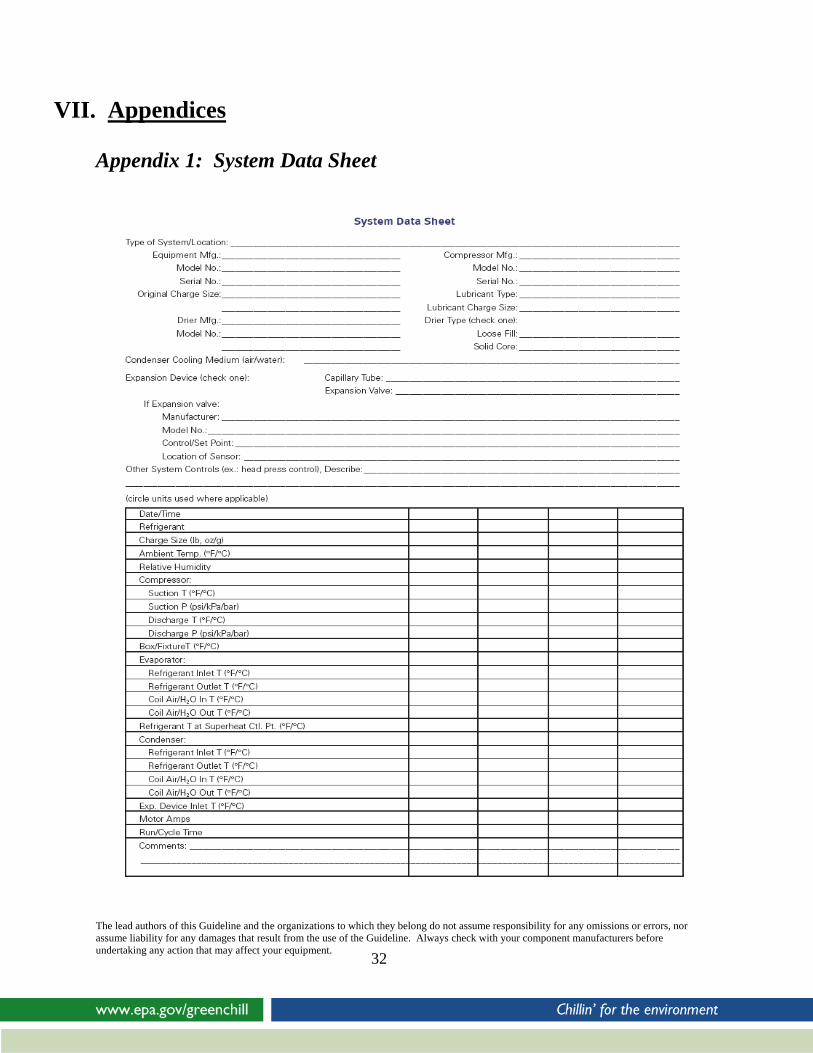
VII. Appendices Appendix 1: System Data Sheet
The lead authors of this Guideline and the organizations to which they belong do not assume responsibility for any omissions or errors, nor assume liability for any damages that result from the use of the Guideline. Always check with your component manufacturers before undertaking any action that may affect your equipment.
32

Appendix 2: Conversion Checklists for Specific HFC Substitute Chemicals
Retrofit Checklist for DuPont™ ISCEON® MO29 ________ 1. Establish baseline performance with existing refrigerant.
• Use the System Data sheet given in Appendix 1 • Note oil type used and system operating data (if system is operating properly). • Check for existing leaks and repair.
________ 2. Remove existing refrigerant charge from system. (Need 10-15 in. Hg [50-67 kPa] vacuum to
remove charge.) • Use recovery cylinder (DO NOT vent to atmosphere). • Weigh amount removed if possible): _______________ • Break the vacuum with dry nitrogen.
________ 3. Replace the filter dryer and seals.
• Change elastomeric seals (O-rings. sight glasses. etc.). • Check that oil is in good condition; replace if necessary.
________ 4. Evacuate system and check for leaks.
• Does the system hold a vacuum? • Break vacuum with dry nitrogen, pressurize to below system design pressure. • Does the system hold pressure? • Check for any leaks.
________ 5. Charge system with ISCEON® MO29 refrigerant.
• Remove liquid only from cylinder. • The initial charge amount should be approximately 85% of the standard charge for R-22
and the final charge amount will be approximately 95%.
________ 6. Adjust TXV and/or refrigerant charge to achieve the same superheat as the original system. If adjustment is not adequate, replace TXV.
________ 7. Monitor oil levels in compressor. If necessary add original oil to attain normal operating level (mid-sight glass).
• If a sudden surge in oil level occurs (e.g., during/just-after defrost) remove a small (approximately 10%) quantity of the mineral oil and replace with POE oil. Repeat if necessary.
• If oil level falls below the minimum, top-up to minimum level. • If the oil level continuously falls or large oscillations occur during operation, add a
sufficient amount of an equivalent POE until oil return becomes normal. ________ 8. Label system clearly. Ensure System Data sheet is completed and filed securely. Retrofit is complete! The lead authors of this Guideline and the organizations to which they belong do not assume responsibility for any omissions or errors, nor assume liability for any damages that result from the use of the Guideline. Always check with your component manufacturers before undertaking any action that may affect your equipment.
33
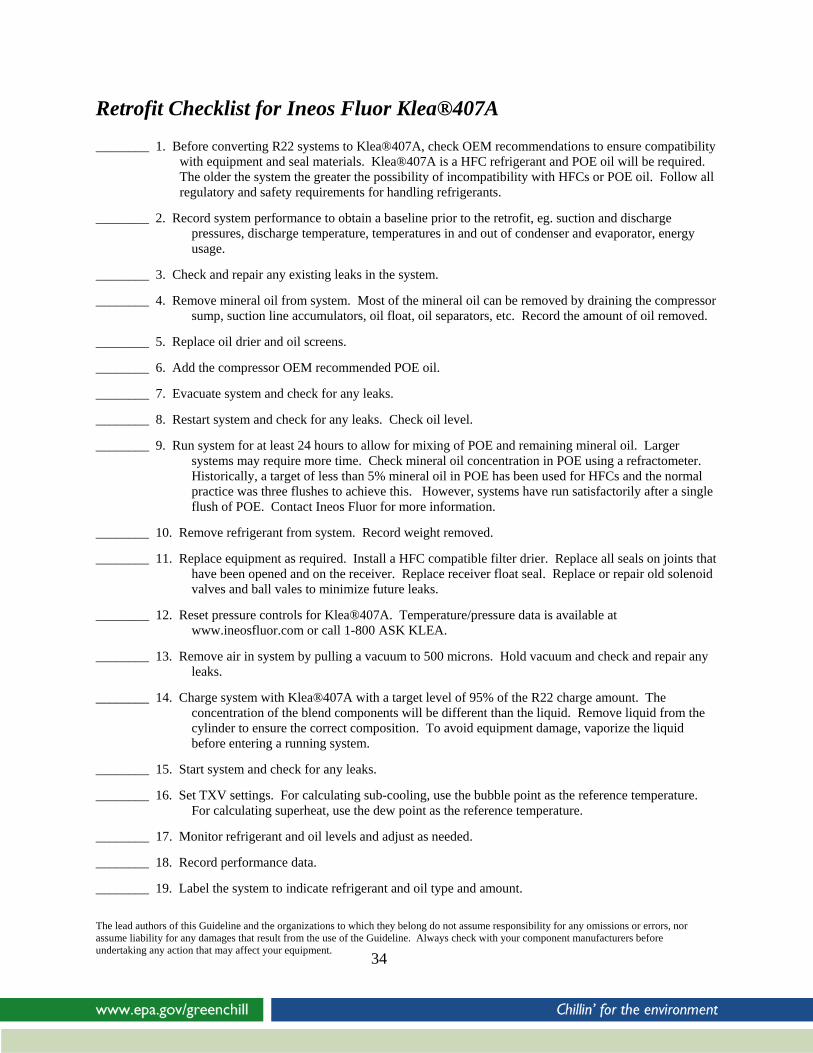
Retrofit Checklist for Ineos Fluor Klea®407A ________ 1. Before converting R22 systems to Klea®407A, check OEM recommendations to ensure compatibility
with equipment and seal materials. Klea®407A is a HFC refrigerant and POE oil will be required. The older the system the greater the possibility of incompatibility with HFCs or POE oil. Follow all regulatory and safety requirements for handling refrigerants.
________ 2. Record system performance to obtain a baseline prior to the retrofit, eg. suction and discharge pressures, discharge temperature, temperatures in and out of condenser and evaporator, energy usage.
________ 3. Check and repair any existing leaks in the system.
________ 4. Remove mineral oil from system. Most of the mineral oil can be removed by draining the compressor sump, suction line accumulators, oil float, oil separators, etc. Record the amount of oil removed.
________ 5. Replace oil drier and oil screens.
________ 6. Add the compressor OEM recommended POE oil.
________ 7. Evacuate system and check for any leaks.
________ 8. Restart system and check for any leaks. Check oil level.
________ 9. Run system for at least 24 hours to allow for mixing of POE and remaining mineral oil. Larger systems may require more time. Check mineral oil concentration in POE using a refractometer. Historically, a target of less than 5% mineral oil in POE has been used for HFCs and the normal practice was three flushes to achieve this. However, systems have run satisfactorily after a single flush of POE. Contact Ineos Fluor for more information.
________ 10. Remove refrigerant from system. Record weight removed.
________ 11. Replace equipment as required. Install a HFC compatible filter drier. Replace all seals on joints that have been opened and on the receiver. Replace receiver float seal. Replace or repair old solenoid valves and ball vales to minimize future leaks.
________ 12. Reset pressure controls for Klea®407A. Temperature/pressure data is available at www.ineosfluor.com or call 1-800 ASK KLEA.
________ 13. Remove air in system by pulling a vacuum to 500 microns. Hold vacuum and check and repair any leaks.
________ 14. Charge system with Klea®407A with a target level of 95% of the R22 charge amount. The concentration of the blend components will be different than the liquid. Remove liquid from the cylinder to ensure the correct composition. To avoid equipment damage, vaporize the liquid before entering a running system.
________ 15. Start system and check for any leaks.
________ 16. Set TXV settings. For calculating sub-cooling, use the bubble point as the reference temperature. For calculating superheat, use the dew point as the reference temperature.
________ 17. Monitor refrigerant and oil levels and adjust as needed.
________ 18. Record performance data.
________ 19. Label the system to indicate refrigerant and oil type and amount.
The lead authors of this Guideline and the organizations to which they belong do not assume responsibility for any omissions or errors, nor assume liability for any damages that result from the use of the Guideline. Always check with your component manufacturers before undertaking any action that may affect your equipment.
34

Retrofit Checklist for Honeywell Genetron 407C Genetron 407C is an HFC blend and a close match to R22 but will require an oil change to a synthetic lubricant. Consult the original equipment manufacturer for recommended lubricants. The mass flow of Genetron 407C is very close to that of R22 and in most cases the existing thermal expansion valves can remain although adjustment may be necessary. Genetron 407C is a refrigerant blend having glide which requires the technician to use dew point values for checking superheat and bubble values for checking sub-cooling. A pressure temperature chart is available at Genetron.com or by contacting Honeywell Refrigerants Technical Service. Retrofit Checklist
________1. Record baseline data on original system performance.
________2. Recover HCFC-22 refrigerant charge using appropriate recovery equipment.
________3. Record the amount of HCFC recovered.
________4. Choose compressor lubricant.
________5. Drain the existing lubricant from the compressors, separators and oil reservoirs.
________6. Measure amount of lubricant removed.
________7. Change lubricant filters if present.
________8. Recharge the system with polyol ester lubricant, use the same amount that was removed.
________9. Traditionally at this point the R22 would be returned to the system and the system run for at least 24 hours to return as much of the residual mineral oil in the system to the compressors and oil management system. Typically an acceptable residual mineral oil content of 5% was the target. Recent field data suggests the possibility of a successful retrofit with only one oil change performed before the addition of Genetron 407C. Consult Honeywell Refrigerants for guidance.
________10. Evaluate the expansion devices; consult the valve manufacturers for recommendations. No change is necessary in most cases.
________11. Evaluate and replace all elastomer seals including receiver float, alarm and level control gaskets.
________12. Replace filter driers and suction filters.
________13. Leak check the system.
________14. Evacuate the system.
________15. Charge the system with Genetron 407C. Remove only liquid from the charging cylinder. Initial charge should be approximately 85% of the R22 charge by weight. Record the amount of refrigerant charged.
________16. Check system operation and adjust TXV’s and operating controls. The discharge pressure of R407C is slightly higher and condenser fan and ambient controls may require adjustment.
________17. Adjust refrigerant charge if necessary, final charge should not exceed 95% of the original R22 charge.
________18. Label components and the system with the type of refrigerant and lubricant.
The lead authors of this Guideline and the organizations to which they belong do not assume responsibility for any omissions or errors, nor assume liability for any damages that result from the use of the Guideline. Always check with your component manufacturers before undertaking any action that may affect your equipment.
35

Retrofit Checklist for Arkema Forane® 427A ________ 1. Establish baseline performance with existing refrigerant.
• Use the System Data sheet in Appendix 1. • Note the oil type in use and system operating data (if system is operating properly). • Check for existing leaks and repair.
________ 2. Remove existing refrigerant charge from system. (Need 10-15 in. Hg
[50-67 kPa] vacuum to remove charge.) • Use recovery cylinder (DO NOT vent to atmosphere). • Weigh amount removed if possible: _______________ • Break the vacuum with dry nitrogen.
________ 3. Replace the filter-drier and seals. • Change elastomeric seals (O-rings, sight glasses, etc.). • Check that oil is in good condition; replace if necessary.
________ 4. Determine oil change requirements.
• If an oil separator is currently used, replacement of original mineral oil or alkylbenzene is often not needed (skip to step 6). • If no oil separator is present, drain existing mineral oil or alkylbenzene from the compressor sump, suction line accumulators, etc. Record the amount of oil removed.
________ 5. Add an equivalent amount of OEM recommended POE oil.
• In most cases, no flushing is required. Only one oil change is required with up to 15% residual AB or mineral oil accommodated.
________ 6. Evacuate system and check for leaks.
• Does the system hold a vacuum? • Does the system hold pressure? • Check for any leaks.
________ 7. Charge system with Forane® 427A refrigerant.
• Remove liquid only from cylinder. • The initial charge amount should be approximately 95% of the standard charge for HCFC-22, topping up to 100% if necessary
________ 8. Adjust TXV setpoint and/or refrigerant charge to achieve the same superheat as the original
system. ________ 9. Monitor oil levels in the compressor. If necessary, add/remove oil to attain normal operating
level (mid sight glass). • If original mineral oil or alkylbenzene used, and oil level surges (e.g. after defrost), falls below minimum, or large oscillations in oil level are observed, replace small amounts (≈ 10 %) of original oil with equivalent POE until satisfactory oil return is achieved.
________ 10. Label system clearly. Ensure System Data sheet is completed and filed securely.
The lead authors of this Guideline and the organizations to which they belong do not assume responsibility for any omissions or errors, nor assume liability for any damages that result from the use of the Guideline. Always check with your component manufacturers before undertaking any action that may affect your equipment.
36

VIII. Acknowledgements
The GreenChill Advanced Refrigeration Partnership is an EPA cooperative alliance with the supermarket industry and other stakeholders to promote advanced technologies, strategies, and practices that reduce refrigerant charges and emissions of ozone-depleting substances and greenhouse gases.
Working with EPA, GreenChill Partners:
• Transition to non-ozone-depleting refrigerants;
• Reduce refrigerant charges; • Reduce both ozone-depleting and
greenhouse gas refrigerant emissions; and
• Promote supermarkets’ adoption of advanced refrigeration technologies.
Lead authors: Keilly Witman – U.S. E.P.A.; Craig Thomas – Arkema; Kevin O’Shea – DuPont; Nick Strickland – DuPont; Ron Vogl – Honeywell; and Sean Cunningham – INEOS Fluor.
Special thanks to others who contributed to the Guideline: Bella Maranion – U.S. E.P.A.; Dave Godwin – U.S. E.P.A.; Julius Banks – U.S. E.P.A.; and Patti Conlan – Arkema.
Special thanks also to the peer reviewers: Jon Perry – Farm Fresh / Supervalu; George Ronn – Supervalu; Michal Shepard – Harris Teeter; Ed Estberg – Raleys; Steve Sloan – Publix Super Markets; Steve Millard – Food Lion; Scott Martin – Hill Phoenix; Steve Hagler – Hussmann; Buzz Schaeffer – Hussmann; Travis Lumpkin – Kysor Warren; Bruce Hierlmeier – Zero Zone, Pat Murphy – NATE; Jerry Weis – HVAC Excellence; and Warren Beeton - Emerson.
The lead authors of this Guideline and the organizations to which they belong do not assume responsibility for any omissions or errors, nor assume liability for any damages that result from the use of the Guideline. Always check with your component manufacturers before undertaking any action that may affect your equipment.
37