Embed Size (px)
Citation preview
EPA 430-B-11-001
GreenChill Best Practices Guideline Commercial Refrigeration Leak Prevention & Repairs
U.S. Environmental Protection Agency Stratospheric Protection Division May 2011
i
DISCLAIMER
This document does not address or assert compliance with the statutory requirements of Section 608, Title VI of the Clean Air Act, as amended in 1990. Nor does this document address or assert compliance with the EPA Section 608 leak repair regulations, at 40 CFR Part 82, Subpart F. The authors of this Guideline, and the companies, agencies, and organizations to which they belong, do not assume responsibility for any omissions or errors, or assume liability for any damages, that result from the use of this Guideline. Always check with your equipment manufacturers for proper procedures for your equipment before undertaking any action that may affect your equipment.
ii
TABLE OF CONTENTS I. INTRODUCTION ..................................................................................................................... 1
Mission ....................................................................................................................................... 1
Purpose and Scope .......................................................................................................................... 1
Refrigerant Leaks from Supermarket Refrigeration Systems .......................................................... 2
II. WHY SYSTEMS LEAK ......................................................................................................... 3
Where Leaks Occur ......................................................................................................................... 3
Compressor Racks .................................................................................................................................. 3 Display Cases ......................................................................................................................................... 4 Remote Air-Cooled Condensers ............................................................................................................. 4 Walk-In Evaporators .............................................................................................................................. 5 Field-Installed Piping ............................................................................................................................. 5 Condensing Units ................................................................................................................................... 5 Remote Headers ..................................................................................................................................... 5
Causes of Leaks............................................................................................................................... 6
III. GETTING STARTED ........................................................................................................... 9
No-Tolerance Policy ....................................................................................................................... 9
Tracking Leaks ................................................................................................................................ 9
IV. PREVENTIVE MAINTENANCE PRACTICES .............................................................. 10
Clean Equipment ........................................................................................................................... 10
Leak Detection Alarm Systems ...................................................................................................... 11
Regular Leak Inspections .............................................................................................................. 11
V. LEAK REPAIRS .................................................................................................................... 12
Response Time .............................................................................................................................. 12
Thoroughness of the Check ........................................................................................................... 12
Follow Up Checks and Verification .............................................................................................. 12
VI. REDUCING LEAK POTENTIAL ..................................................................................... 13
Overcharged Systems .................................................................................................................... 13
System Component Upgrades ....................................................................................................... 13
Additional Recommendations ....................................................................................................... 13
APPENDIX A. SUPERMARKET WALK-THRU CHECKLIST ......................................... 15
APPENDIX B. MONTHLY REFRIGERANT RECEIVER LEVEL CHART 2011-2012 . 17
1
I. Introduction
Mission GreenChill’s mission in developing this document is to assist food retailers in reducing refrigerant leaks in their commercial refrigeration systems.
Purpose and Scope The purpose of this Best Practices Guideline is to provide food retailers with information on best practices for reducing refrigerant leaks from commercial refrigeration systems. The Guideline only covers practices implemented during the design and operation of a refrigeration system and does not discuss leak prevention practices during the installation of equipment. Information on leak-tight installations can be found in GreenChill’s Best Practices Guideline: Ensuring Leak-Tight Installations of Refrigeration Equipment.1
While GreenChill preferably encourages the adoption of advanced refrigeration as a means for reducing refrigerant emissions, the partnership also recognizes the importance of proper servicing and maintenance practices in refrigeration management strategies. This Guideline document focuses on practices largely relevant to traditional centralized direct expansion (DX) systems; however, most practices also are applicable to other system types such as distributed systems and secondary loop systems. Specifically, the Guideline provides information on the following:
• Why systems leak; • Tracking refrigerant charges; • Preventative maintenance practices; • Responding to leaks; and • Reducing leak potential.
This Guideline document does not address compliance issues associated with EPA regulations promulgated under Title VI of the Clean Air Act, as amended in 1990, including the regulatory leak repair provisions under Section 608 of the Clean Air Act.
1 Available at http://www.epa.gov/greenchill/downloads/LeakGuidelines.pdf
2
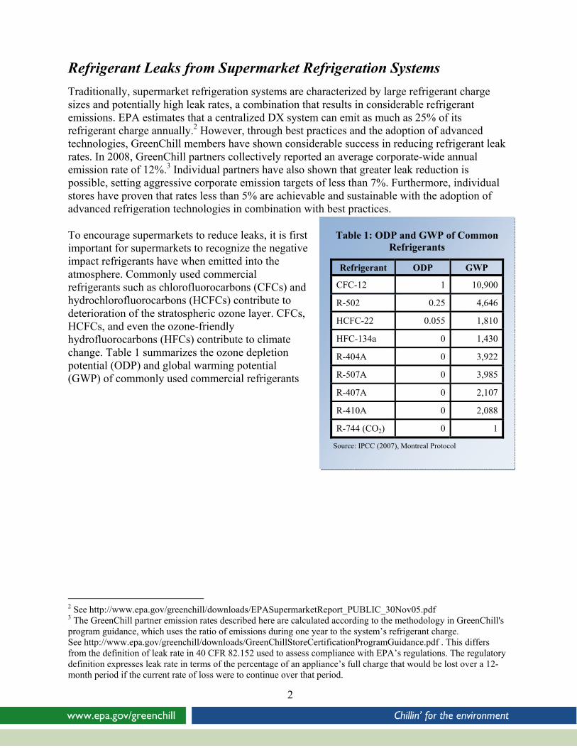
Table 1: ODP and GWP of Common Refrigerants
Refrigerant ODP GWP
CFC-12 1 10,900
R-502 0.25 4,646
HCFC-22 0.055 1,810
HFC-134a 0 1,430
R-404A 0 3,922
R-507A 0 3,985
R-407A 0 2,107
R-410A 0 2,088
R-744 (CO2) 0 1
Source: IPCC (2007), Montreal Protocol
Refrigerant Leaks from Supermarket Refrigeration Systems Traditionally, supermarket refrigeration systems are characterized by large refrigerant charge sizes and potentially high leak rates, a combination that results in considerable refrigerant emissions. EPA estimates that a centralized DX system can emit as much as 25% of its refrigerant charge annually.2 However, through best practices and the adoption of advanced technologies, GreenChill members have shown considerable success in reducing refrigerant leak rates. In 2008, GreenChill partners collectively reported an average corporate-wide annual emission rate of 12%.3 Individual partners have also shown that greater leak reduction is possible, setting aggressive corporate emission targets of less than 7%. Furthermore, individual stores have proven that rates less than 5% are achievable and sustainable with the adoption of advanced refrigeration technologies in combination with best practices.
To encourage supermarkets to reduce leaks, it is first important for supermarkets to recognize the negative impact refrigerants have when emitted into the atmosphere. Commonly used commercial refrigerants such as chlorofluorocarbons (CFCs) and hydrochlorofluorocarbons (HCFCs) contribute to deterioration of the stratospheric ozone layer. CFCs, HCFCs, and even the ozone-friendly hydrofluorocarbons (HFCs) contribute to climate change. Table 1 summarizes the ozone depletion potential (ODP) and global warming potential (GWP) of commonly used commercial refrigerants
2 See http://www.epa.gov/greenchill/downloads/EPASupermarketReport_PUBLIC_30Nov05.pdf 3 The GreenChill partner emission rates described here are calculated according to the methodology in GreenChill's program guidance, which uses the ratio of emissions during one year to the system’s refrigerant charge. See http://www.epa.gov/greenchill/downloads/GreenChillStoreCertificationProgramGuidance.pdf . This differs from the definition of leak rate in 40 CFR 82.152 used to assess compliance with EPA’s regulations. The regulatory definition expresses leak rate in terms of the percentage of an appliance’s full charge that would be lost over a 12-month period if the current rate of loss were to continue over that period.
3
II. Why Systems Leak
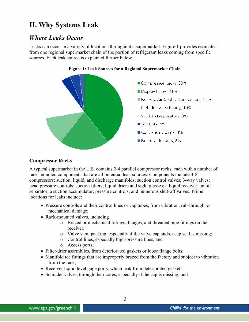
Where Leaks Occur Leaks can occur in a variety of locations throughout a supermarket. Figure 1 provides estimates from one regional supermarket chain of the portion of refrigerant leaks coming from specific sources. Each leak source is explained further below.
Figure 1: Leak Sources for a Regional Supermarket Chain
Compressor Racks A typical supermarket in the U.S. contains 2-4 parallel compressor racks, each with a number of rack-mounted components that are all potential leak sources. Components include 3-8 compressors; suction, liquid, and discharge manifolds; suction control valves; 3-way valves; head pressure controls; suction filters; liquid driers and sight glasses; a liquid receiver; an oil separator; a suction accumulator; pressure controls; and numerous shut-off valves. Prime locations for leaks include:
• Pressure controls and their control lines or cap tubes, from vibration, rub-through, or mechanical damage;
• Rack-mounted valves, including o Brazed or mechanical fittings, flanges, and threaded pipe fittings on the
receiver; o Valve stem packing, especially if the valve cap and/or cap seal is missing; o Control lines, especially high-pressure lines; and o Access ports;
• Filter/drier assemblies, from deteriorated gaskets or loose flange bolts; • Manifold tee fittings that are improperly brazed from the factory and subject to vibration
from the rack; • Receiver liquid level gage ports, which leak from deteriorated gaskets; • Schrader valves, through their cores, especially if the cap is missing; and
4
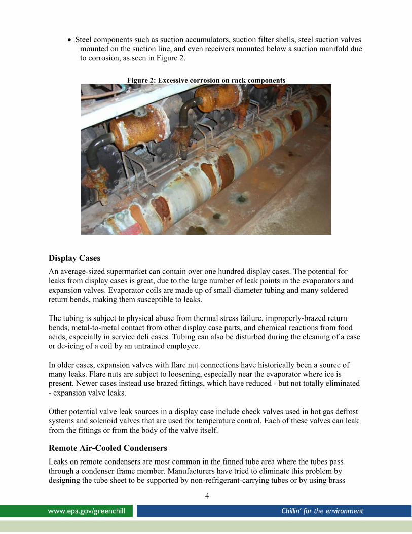
• Steel components such as suction accumulators, suction filter shells, steel suction valves mounted on the suction line, and even receivers mounted below a suction manifold due to corrosion, as seen in Figure 2.
Figure 2: Excessive corrosion on rack components
Display Cases An average-sized supermarket can contain over one hundred display cases. The potential for leaks from display cases is great, due to the large number of leak points in the evaporators and expansion valves. Evaporator coils are made up of small-diameter tubing and many soldered return bends, making them susceptible to leaks.
The tubing is subject to physical abuse from thermal stress failure, improperly-brazed return bends, metal-to-metal contact from other display case parts, and chemical reactions from food acids, especially in service deli cases. Tubing can also be disturbed during the cleaning of a case or de-icing of a coil by an untrained employee.
In older cases, expansion valves with flare nut connections have historically been a source of many leaks. Flare nuts are subject to loosening, especially near the evaporator where ice is present. Newer cases instead use brazed fittings, which have reduced - but not totally eliminated - expansion valve leaks.
Other potential valve leak sources in a display case include check valves used in hot gas defrost systems and solenoid valves that are used for temperature control. Each of these valves can leak from the fittings or from the body of the valve itself.
Remote Air-Cooled Condensers Leaks on remote condensers are most common in the finned tube area where the tubes pass through a condenser frame member. Manufacturers have tried to eliminate this problem by designing the tube sheet to be supported by non-refrigerant-carrying tubes or by using brass
5
ferrules between the tubes and the frame. As a result of thermal expansion or improper rigging of the condenser during installation, the brass ferrules can fall out, causing the condenser tube to contact the condenser frame, which over time may create a leak. Brazed joints on return bends and manifolds are also a potential source of leaks.
One major cause of significant refrigerant leaks on remote condensers is a failure of the motor mount/fan blade assembly. Most manufacturers have improved the design of the fan motor mounting to reduce this problem but not totally eliminate it. In many cases the motor mount failure is preceded by a failure of the fan assembly. Fan blades are often constructed using a steel hub assembly with multiple aluminum or steel fan blades riveted to the hub. Due to cycling of the fan motor, over time the rivets on the individual blades may loosen or the blade itself may begin to tear. If the fan assembly is not replaced, the blade may detach from the fan hub, causing a major imbalance of the fan motor assembly. This extreme vibration may in turn cause the motor support bracket to fail and the fan motor assembly to fall into the fin tube surface, resulting in major damage to the fin tube assembly and possibly a rupture of one or more refrigerant-carrying condenser tubes.
Receivers mounted under condensers along with liquid drier shells, head pressure valves, and other components are subject to the same leaks as those mounted on the compressor racks. Such leaks are just more difficult to detect due to the remote outdoor location.
Walk-In Evaporators
An average supermarket contains only about sixteen walk-in evaporator coils. The leak points in the walk-in coil are similar to those in the refrigerated cases. Walk-in evaporators generally have more solenoid valves and check valves than display cases, resulting in a higher leak potential. Since walk-in evaporators are accessible and located in an enclosed space, however, leaks from these units are more readily detected with a leak detector.
Field-Installed Piping
Field-installed piping consists of all suction, liquid, and discharge piping that connects the compressor racks, display cases, walk-in evaporators, and remote air-cooled condensers. Leaks can occur at any one of the hundreds of brazed connections and thousands of feet of piping in a typical store. If care is not taken to isolate the copper piping from the steel support system, thermal expansion or vibration can create constant movement of the soft copper tubing against the harder steel supports, resulting in development of rub-through leaks over time.
Condensing Units
A condensing unit comprises a single compressor, an air-cooled condenser, and a receiver. Like compressor racks, condensing units also contain valves, filter/driers, and pressure controls, all of which are potential leak sources.
Remote Headers
Remote headers are becoming more common in supermarkets to reduce the number of piping runs from a central point near the sales area back to the compressor room. In contrast to headers installed on compressor racks, remote headers are able to eliminate vibrations and the attendant
6
risk of leaks. While less prone to leaks, they are usually less accessible and might not be checked as frequently as a central compressor room.
Causes of Leaks Leaks are caused by the inevitable wear and tear on a refrigeration system as well as poor design and improper installation,4 servicing, and maintenance practices, such as:
• Poor brazing techniques. Leaks can result from improper brazing techniques such as improper cleaning of the joint prior to brazing, using the wrong brazing alloy, and failure to heat the joint uniformly or to the proper temperature before filling the joint with brazing alloy.
• Improperly tightened fittings. Leaks occur from threaded and flared fittings either when they are not tightened sufficiently or when they are over-tightened and crack.
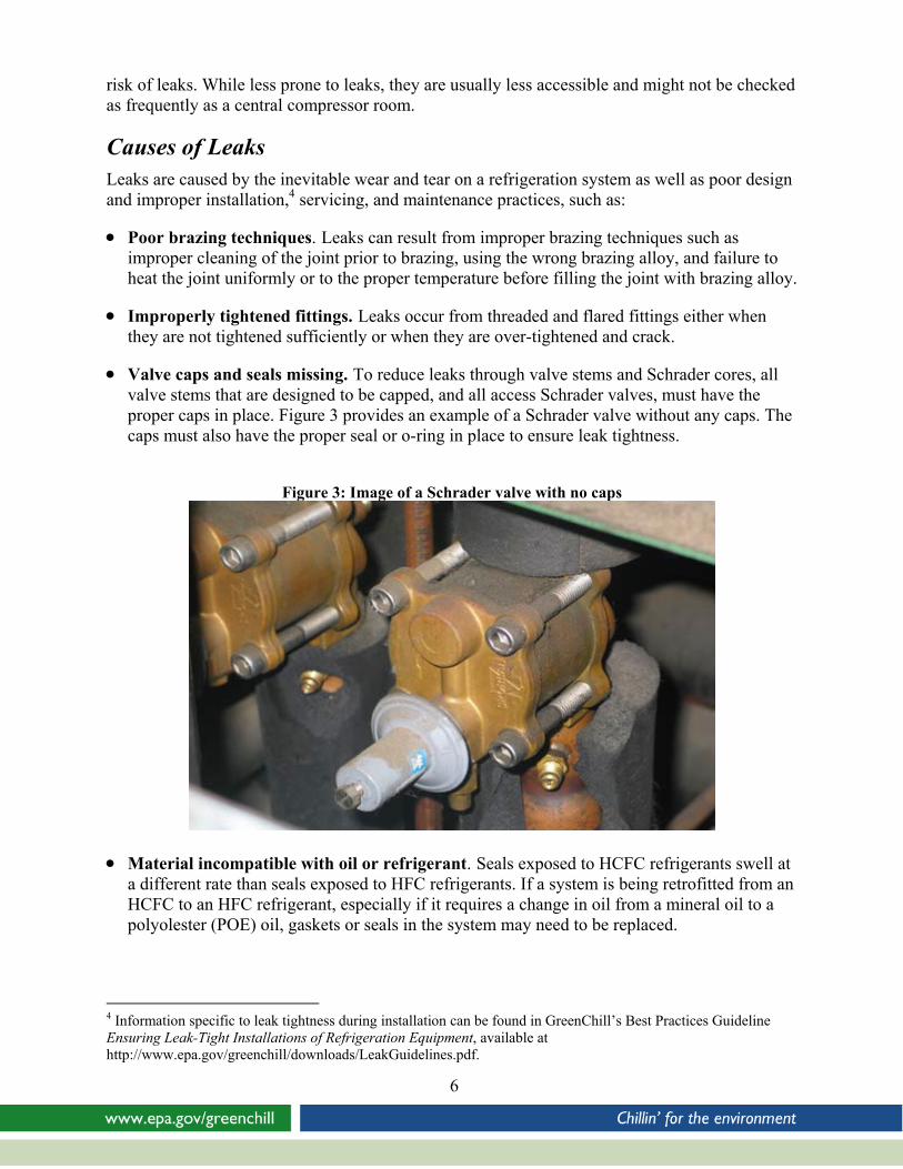
• Valve caps and seals missing. To reduce leaks through valve stems and Schrader cores, all valve stems that are designed to be capped, and all access Schrader valves, must have the proper caps in place. Figure 3 provides an example of a Schrader valve without any caps. The caps must also have the proper seal or o-ring in place to ensure leak tightness.
Figure 3: Image of a Schrader valve with no caps
• Material incompatible with oil or refrigerant. Seals exposed to HCFC refrigerants swell at a different rate than seals exposed to HFC refrigerants. If a system is being retrofitted from an HCFC to an HFC refrigerant, especially if it requires a change in oil from a mineral oil to a polyolester (POE) oil, gaskets or seals in the system may need to be replaced.
4 Information specific to leak tightness during installation can be found in GreenChill’s Best Practices Guideline Ensuring Leak-Tight Installations of Refrigeration Equipment, available at http://www.epa.gov/greenchill/downloads/LeakGuidelines.pdf.
7
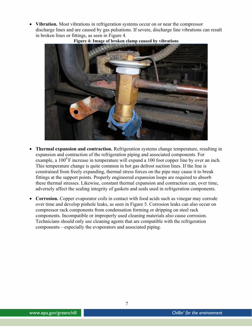
• Vibration. Most vibrations in refrigeration systems occur on or near the compressor discharge lines and are caused by gas pulsations. If severe, discharge line vibrations can result in broken lines or fittings, as seen in Figure 4.
Figure 4: Image of broken clamp caused by vibrations
• Thermal expansion and contraction. Refrigeration systems change temperature, resulting in expansion and contraction of the refrigeration piping and associated components. For example, a 1000 F increase in temperature will expand a 100 foot copper line by over an inch. This temperature change is quite common in hot gas defrost suction lines. If the line is constrained from freely expanding, thermal stress forces on the pipe may cause it to break fittings at the support points. Properly engineered expansion loops are required to absorb these thermal stresses. Likewise, constant thermal expansion and contraction can, over time, adversely affect the sealing integrity of gaskets and seals used in refrigeration components.
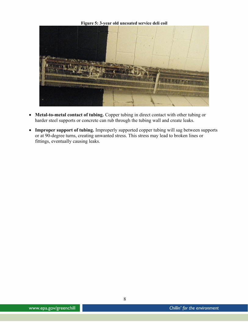
• Corrosion. Copper evaporator coils in contact with food acids such as vinegar may corrode over time and develop pinhole leaks, as seen in Figure 5. Corrosion leaks can also occur on compressor rack components from condensation forming or dripping on steel rack components. Incompatible or improperly used cleaning materials also cause corrosion. Technicians should only use cleaning agents that are compatible with the refrigeration components—especially the evaporators and associated piping.
8
Figure 5: 3-year old uncoated service deli coil
• Metal-to-metal contact of tubing. Copper tubing in direct contact with other tubing or harder steel supports or concrete can rub through the tubing wall and create leaks.
• Improper support of tubing. Improperly supported copper tubing will sag between supports or at 90-degree turns, creating unwanted stress. This stress may lead to broken lines or fittings, eventually causing leaks.
9
III. Getting Started
No-Tolerance Policy Supermarket employees manage and run their business with the goal of meeting their customers’ needs. Although most companies understand the importance of minimizing leaks, competing responsibilities often get in the way of making refrigerant management a priority. Identifying leaks as a high priority is an important step in ensuring proper maintenance and repair of refrigeration systems. Companies should establish a corporate-wide no-tolerance policy for refrigerant leaks. Establishing a no-tolerance leak policy increases store managers’ and service technicians’ awareness of system maintenance and leak repair. Increased awareness reduces the likelihood that leak checks and tests will get overlooked and helps prevent unnecessary leaks.
In supporting a no-tolerance policy, senior management must openly acknowledge and encourage the policy in order to reinforce the message throughout the company and among its employees.
Highlighting savings in both refrigerant and servicing costs will help senior management get on board with a no-tolerance policy. Common commercial refrigerants cost between $6-10 per pound of refrigerant.5 Based on these prices and assumed servicing costs, refrigerant leaks could cost a supermarket more than $10,000 each year. Clearly, refrigerant leaks are not only harmful for the environment but also are bad for a company’s bottom line.
Tracking Leaks In addition to making leak prevention a priority, a supermarket should incorporate a leak tracking system into its refrigerant management program. A tracking system enables a company to easily quantify leaks, isolate leak sources, and manage refrigerant leaks across multiple stores and systems. It also lets a company benchmark its data against industry trends and set and meet leak reduction goals. A tracking system also lets a company hold individual stores accountable for their leaks and makes it possible to reward store employees, service technicians, or contractors for good practices.
A supermarket can use either a manual leak tracking system or tracking system software. Tracking software – depending on the type used – can help automate the tracking of refrigerant inventories, servicing dates, system capacities, leak amounts and frequencies, and component failures. It can also generate automatic alerts if conditions warrant.
5 Range represents costs of R-22, R-404A, and R-507 on May 20, 2010 from http://www.r22.org/.
10
IV. Preventive Maintenance Practices
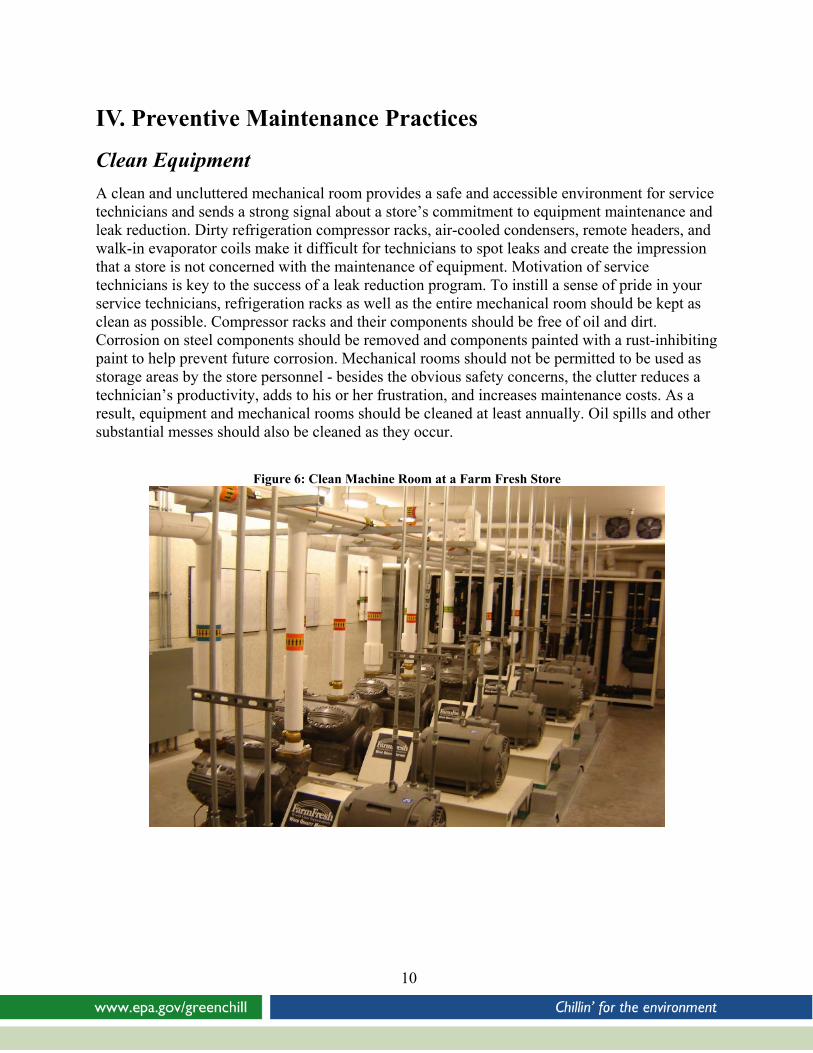
Clean Equipment A clean and uncluttered mechanical room provides a safe and accessible environment for service technicians and sends a strong signal about a store’s commitment to equipment maintenance and leak reduction. Dirty refrigeration compressor racks, air-cooled condensers, remote headers, and walk-in evaporator coils make it difficult for technicians to spot leaks and create the impression that a store is not concerned with the maintenance of equipment. Motivation of service technicians is key to the success of a leak reduction program. To instill a sense of pride in your service technicians, refrigeration racks as well as the entire mechanical room should be kept as clean as possible. Compressor racks and their components should be free of oil and dirt. Corrosion on steel components should be removed and components painted with a rust-inhibiting paint to help prevent future corrosion. Mechanical rooms should not be permitted to be used as storage areas by the store personnel - besides the obvious safety concerns, the clutter reduces a technician’s productivity, adds to his or her frustration, and increases maintenance costs. As a result, equipment and mechanical rooms should be cleaned at least annually. Oil spills and other substantial messes should also be cleaned as they occur.
Figure 6: Clean Machine Room at a Farm Fresh Store
11
Leak Detection Alarm Systems Each store should have a refrigerant leak monitoring and alarm system to ensure a response to major leaks that could develop between regular leak inspections. Leak detection systems are either direct or indirect. A direct detection system directly measures the refrigerant in an air sample taken near a refrigeration system or one of its components. An indirect system measures changes in receiver refrigerant levels, the weight of the condenser/receiver assembly, or system temperature. Often the first notification of a refrigerant leak comes from a temperature sensor that actuates a temperature alarm as the rack starts to run low on refrigerant.
One low-cost alarm system that can be easily incorporated into most stores uses a system temperature sensor that measures the temperature of the system farthest from the compressor rack, which is the first location likely to be affected by a low refrigerant charge. This system should be programmed with an alarm temperature as close to set point as possible without triggering nuisance alarms. When this temperature alarm is activated, it should be treated as a refrigerant leak alarm. Regardless of the type of system chosen, the monitoring system needs to be tied to an alarm system that proactively notifies store management of potential leaks. Furthermore, levels of redundancy or checks in the alarm system procedure should be in place to ensure that the alarm is not ignored.
Unfortunately, direct central leak detection systems are not ideal in highly-vented locations due to the rapid dilution of the refrigerant sample in the ambient air. Since remote air-cooled condensers are located outdoors, refrigerant loss from such units can only be detected using an indirect leak detection system or during preventative leak checks. Similarly, it can be challenging to apply direct central refrigerant leak detection to condensing units with unit-mounted air cooled condensers, due to the volume of air changes the condensers require. As a result, regular leak inspections are extremely important and should not be overlooked.
Regular Leak Inspections On a regular basis service technicians should check receiver levels, compare refrigerant levels to data from the previous visit, and walk through the store with portable device. The GreenChill Checklist for a Walk-Thru Leak Check of a Supermarket and the Receiver Refrigerant-Level Chart, in Appendix A and Appendix B, respectively, should be used for this purpose. Checks should be done every one to two months, based on the size of the system and the system type. Large central DX systems need to be checked more frequently while secondary systems with mechanical room refrigerant monitoring may be checked less often.
12
V. Leak Repairs
Response Time A supermarket company should establish a corporate policy for responding to a refrigerant leak alarm. It should establish both a maximum response time and a process for finding and repairing the leak once a service technician is on site. The response time should be as short as reasonably possible, normally two to four hours in most areas. In the event of a major leak, large quantities of refrigerant can leak out of a system in a short period, so a fast response time could prevent a considerable amount of refrigerant from leaking to the atmosphere.
Under no circumstances should a leaky system be left prior to the identification and repair of the leak. If a major component that is not readily available is leaking and needs to be replaced, that component should be isolated from the system or given a temporary repair, if possible. Simply adding more refrigerant to the system (i.e., topping off the system) is not considered a viable solution to addressing a leak.
Thoroughness of the Check In many cases the first refrigerant leak found in a leak check may not be the only leak in the system. In fact, it might not be the leak responsible for most of a refrigerant loss. Therefore, each technician should understand the correlation between the quantity of refrigerant charge lost and the leak rate of the leak found. If the leak found is too small to leak the quantity of refrigerant lost, the technician should assume there is another leak in the system and continue the leak search.
Follow Up Checks and Verification Once the repair is made, the system should be checked to verify it is leak-free. The verification should include a check of the repaired area as well as the receiver level to ensure that no additional refrigerant was lost. A drop in receiver level is an indication that there could be more leaks in the system.
13
VI. Reducing Leak Potential
Overcharged Systems A refrigeration system may require a “winter charge,” in which more refrigerant is used in the winter to permit flooding of the condenser to maintain a minimum operating system head pressure. This charge should be kept as small as possible by using split-condenser valves, fan cycling, and floating head pressure control. System charges can also vary significantly if the rack is piped to a heat recovery coil or uses a gas-type defrost. The total annual refrigerant charge is the charge required to feed expansion valves with saturated liquid refrigerant at the time when the system charge requirement is at its maximum, and no more. This total annual charge may only be needed for a relatively few hours a year and is stored the rest of the time in the system’s receiver. As a result, a system could have an excess refrigerant charge in the receiver over 90% of the time.
If a leak occurs during this 90% period, it might be possible to lose the entire receiver charge before the refrigerant loss begins to affect case temperatures. To minimize the potential for such loss, it is important to document the receiver levels during winter and summer conditions as well as when the system is in defrost or heat recovery mode. These levels should be posted on the refrigeration rack or in some other convenient location that is readily available to any service tech who would be charging the system after a leak. It is common practice for service technicians to charge additional refrigerant to a system as a safety buffer. This buffer refrigerant will add to the potential loss, and a policy should be instituted to avoid this practice.
System Component Upgrades System components should be replaced with parts that are more leak-resistant or have a reduced number of potential leak sources. For example, discharge-piloted evaporator pressure regulating (EPR) valves may be replaced with suction stepper valves, which eliminate the high-side control line, provide better temperature control, and are generally more reliable. Suction and liquid manifolds may be replaced with loop piping systems or remote manifolds to reduce the number of fittings subject to rack vibration. During major remodels, you may also want to consider replacing centralized DX racks with distributed systems, secondary loop systems, or CO2 systems to further reduce leak potential.
Additional Recommendations A store can further reduce the leak potential of its existing refrigeration system by following these recommendations:
Replace flared connection components with brazed connection components.
Replace valves with bolted connections with hermetic one-piece valves with no mechanical joints.
Replace valves with control lines with valves that don’t require control lines.
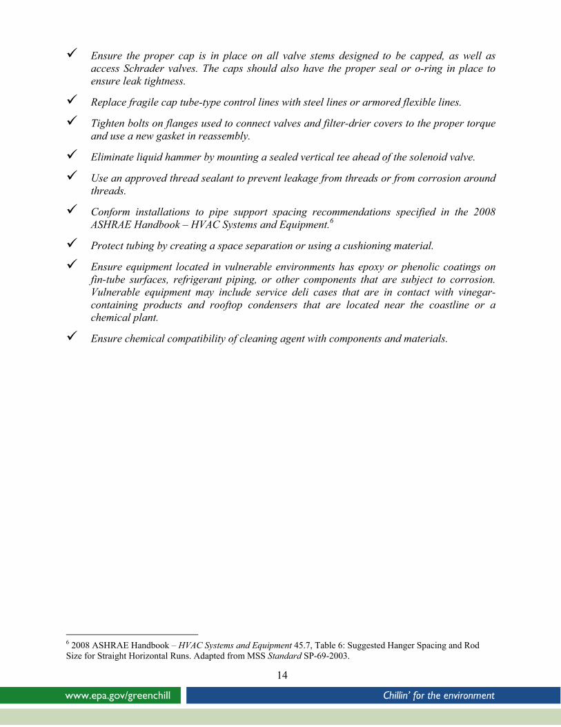
Ensure the proper cap is in place on all valve stems designed to be capped, as well as
access Schrader valves. The caps should also have the proper seal or o-ring in place to ensure leak tightness.
Replace fragile cap tube-type control lines with steel lines or armored flexible lines.
Tighten bolts on flanges used to connect valves and filter-drier covers to the proper torque and use a new gasket in reassembly.
Eliminate liquid hammer by mounting a sealed vertical tee ahead of the solenoid valve.
Use an approved thread sealant to prevent leakage from threads or from corrosion around threads.
Conform installations to pipe support spacing recommendations specified in the 2008 ASHRAE Handbook – HVAC Systems and Equipment.6
Protect tubing by creating a space separation or using a cushioning material.
Ensure equipment located in vulnerable environments has epoxy or phenolic coatings on fin-tube surfaces, refrigerant piping, or other components that are subject to corrosion. Vulnerable equipment may include service deli cases that are in contact with vinegar-containing products and rooftop condensers that are located near the coastline or a chemical plant.
Ensure chemical compatibility of cleaning agent with components and materials.
14
6 2008 ASHRAE Handbook – HVAC Systems and Equipment 45.7, Table 6: Suggested Hanger Spacing and Rod Size for Straight Horizontal Runs. Adapted from MSS Standard SP-69-2003.
15
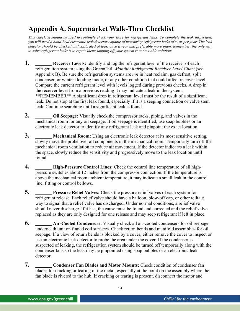
Appendix A. Supermarket Walk-Thru Checklist This checklist should be used to routinely check your store for refrigerant leaks. To complete the leak inspection, you will need a hand-held electronic leak detector capable of measuring refrigerant leaks of ½ oz per year. The leak detector should be checked and calibrated at least once a year and preferably more often. Remember, the only way to solve refrigerant leaks is to repair them; topping-off your system is not a viable solution!
1. _______ Receiver Levels: Identify and log the refrigerant level of the receiver of each refrigeration system using the GreenChill Monthly Refrigerant Receiver Level Chart (see Appendix B). Be sure the refrigeration systems are not in heat reclaim, gas defrost, split condenser, or winter flooding mode, or any other condition that could affect receiver level. Compare the current refrigerant level with levels logged during previous checks. A drop in the receiver level from a previous reading it may indicate a leak in the system. **REMEMBER** A significant drop in refrigerant level must be the result of a significant leak. Do not stop at the first leak found, especially if it is a seeping connection or valve stem leak. Continue searching until a significant leak is found.
2. _______ Oil Seepage: Visually check the compressor racks, piping, and valves in the mechanical room for any oil seepage. If oil seepage is identified, use soap bubbles or an electronic leak detector to identify any refrigerant leak and pinpoint the exact location.
3. _______ Mechanical Room: Using an electronic leak detector at its most sensitive setting, slowly move the probe over all components in the mechanical room. Temporarily turn off the mechanical room ventilation to reduce air movement. If the detector indicates a leak within the space, slowly reduce the sensitivity and progressively move to the leak location until found.
4. _______ High-Pressure Control Lines: Check the control line temperature of all high-pressure switches about 12 inches from the compressor connection. If the temperature is above the mechanical room ambient temperature, it may indicate a small leak in the control line, fitting or control bellows.
5. _______ Pressure Relief Valves: Check the pressure relief valves of each system for refrigerant release. Each relief valve should have a balloon, blow-off cap, or other telltale way to signal that a relief valve has discharged. Under normal conditions, a relief valve should never discharge. If it has, the cause must be found and corrected and the relief valve replaced as they are only designed for one release and may seep refrigerant if left in place.
6. _______ Air-Cooled Condensers: Visually check all air-cooled condensers for oil seepage underneath unit on finned coil surfaces. Check return bends and manifold assemblies for oil seepage. If a view of return bends is blocked by a cover, either remove the cover to inspect or use an electronic leak detector to probe the area under the cover. If the condenser is suspected of leaking, the refrigeration system should be turned off temporarily along with the condenser fans so the leak may be pinpointed using soap bubbles or an electronic leak detector.
7. _______ Condenser Fan Blades and Motor Mounts: Check condition of condenser fan blades for cracking or tearing of the metal, especially at the point on the assembly where the fan blade is riveted to the hub. If cracking or tearing is present, disconnect the motor and
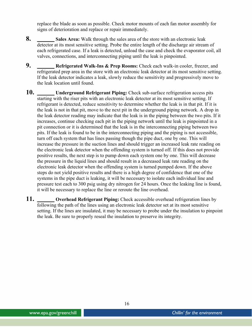
replace the blade as soon as possible. Check motor mounts of each fan motor assembly for signs of deterioration and replace or repair immediately.
8. _______ Sales Area: Walk through the sales area of the store with an electronic leak detector at its most sensitive setting. Probe the entire length of the discharge air stream of each refrigerated case. If a leak is detected, unload the case and check the evaporator coil, all valves, connections, and interconnecting piping until the leak is pinpointed.
9. _______ Refrigerated Walk-Ins & Prep Rooms: Check each walk-in cooler, freezer, and refrigerated prep area in the store with an electronic leak detector at its most sensitive setting. If the leak detector indicates a leak, slowly reduce the sensitivity and progressively move to the leak location until found.
10. _______ Underground Refrigerant Piping: Check sub-surface refrigeration access pits starting with the riser pits with an electronic leak detector at its most sensitive setting. If refrigerant is detected, reduce sensitivity to determine whether the leak is in that pit. If it is the leak is not in that pit, move to the next pit in the underground piping network. A drop in the leak detector reading may indicate that the leak is in the piping between the two pits. If it increases, continue checking each pit in the piping network until the leak is pinpointed in a pit connection or it is determined that the leak is in the interconnecting piping between two pits. If the leak is found to be in the interconnecting piping and the piping is not accessible, turn off each system that has lines passing though the pipe duct, one by one. This will increase the pressure in the suction lines and should trigger an increased leak rate reading on the electronic leak detector when the offending system is turned off. If this does not provide positive results, the next step is to pump down each system one by one. This will decrease the pressure in the liquid lines and should result in a decreased leak rate reading on the electronic leak detector when the offending system is turned pumped down. If the above steps do not yield positive results and there is a high degree of confidence that one of the systems in the pipe duct is leaking, it will be necessary to isolate each individual line and pressure test each to 300 psig using dry nitrogen for 24 hours. Once the leaking line is found, it will be necessary to replace the line or reroute the line overhead.
11. _______ Overhead Refrigerant Piping: Check accessible overhead refrigeration lines by following the path of the lines using an electronic leak detector set at its most sensitive setting. If the lines are insulated, it may be necessary to probe under the insulation to pinpoint the leak. Be sure to properly reseal the insulation to preserve its integrity.
16
17
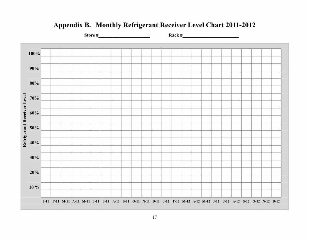
Appendix B. Monthly Refrigerant Receiver Level Chart 2011-2012 Store #______________________ Rack #________________________
Ref
rige
rant
Rec
eive
r L
evel
100%
90%
80%
70%
60%
50%
40%
30%
20%
10 %
J-11 F-11 M-11 A-11 M-11 J-11 J-11 A-11 S-11 O-11 N-11 D-11 J-12 F-12 M-12 A-12 M-12 J-12 J-12 A-12 S-12 O-12 N-12 D-12