Embed Size (px)
Citation preview
Green Building Design Project
Frederick Avyasa Smith & Ayotunde Adenaike
MECE E4314: Energy Dynamics of Green Buildings
Prof. Mohammad H. Naraghi
May 11th, 2015
1

Table of Contents
Introduction........................................................................................................................................... 3
Floor Plan................................................................................................................................................ 3Floor Plan of Theoretical House................................................................................................................. 3Floor Plan of Theoretical House Including Dimensions.....................................................................4Orientation of Theoretical House............................................................................................................... 4
Construction.......................................................................................................................................... 5General Design Parameters of Theoretical House................................................................................5Construction Materials................................................................................................................................... 6Detailed Elements of All Windows and Doors........................................................................................7Infiltration Calculation................................................................................................................................... 7
Ventilation.............................................................................................................................................. 8View 1 of Theoretical House.........................................................................................................................9View 2 of Theoretical House...................................................................................................................... 10View 3 of Theoretical House...................................................................................................................... 11View 4 of Theoretical House...................................................................................................................... 12
Appliances............................................................................................................................................. 12Description of Appliances........................................................................................................................... 12
Photovoltaic System......................................................................................................................... 13General Information of PV System...........................................................................................................13Detailed Information of PV System......................................................................................................... 13
U-Factors.............................................................................................................................................. 13Cooling and Heating Load Values.............................................................................................................14Heat Pump Specifications........................................................................................................................... 14
HVAC System Layout......................................................................................................................... 15Overall Layout of HVAC System................................................................................................................ 15Heat Pump, Air Handler Unit, and HRV Unit Layout..........................................................................16Supply Air Ductwork Layout......................................................................................................................17Return Air Ductwork Layout..................................................................................................................... 18Exhaust Return Air Ductwork Layout.....................................................................................................19
Conclusion............................................................................................................................................ 20Energy Consumption Per Year.................................................................................................................. 20Breakdown of Energy Consumption Per Year.....................................................................................20Building Energy Performance Standards..............................................................................................21
References............................................................................................................................................ 22
2

3
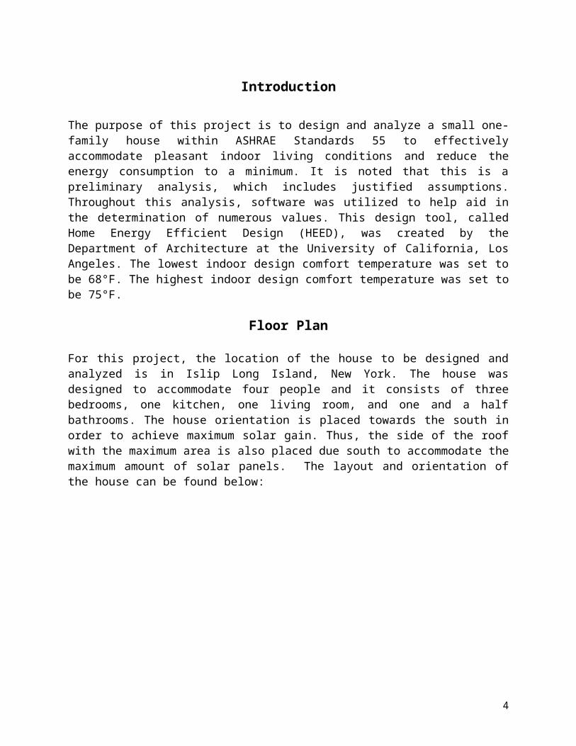
Introduction
The purpose of this project is to design and analyze a small one-family house within ASHRAE Standards 55 to effectively accommodate pleasant indoor living conditions and reduce the energy consumption to a minimum. It is noted that this is a preliminary analysis, which includes justified assumptions. Throughout this analysis, software was utilized to help aid in the determination of numerous values. This design tool, called Home Energy Efficient Design (HEED), was created by the Department of Architecture at the University of California, Los Angeles. The lowest indoor design comfort temperature was set to be 68°F. The highest indoor design comfort temperature was set to be 75°F.
Floor Plan
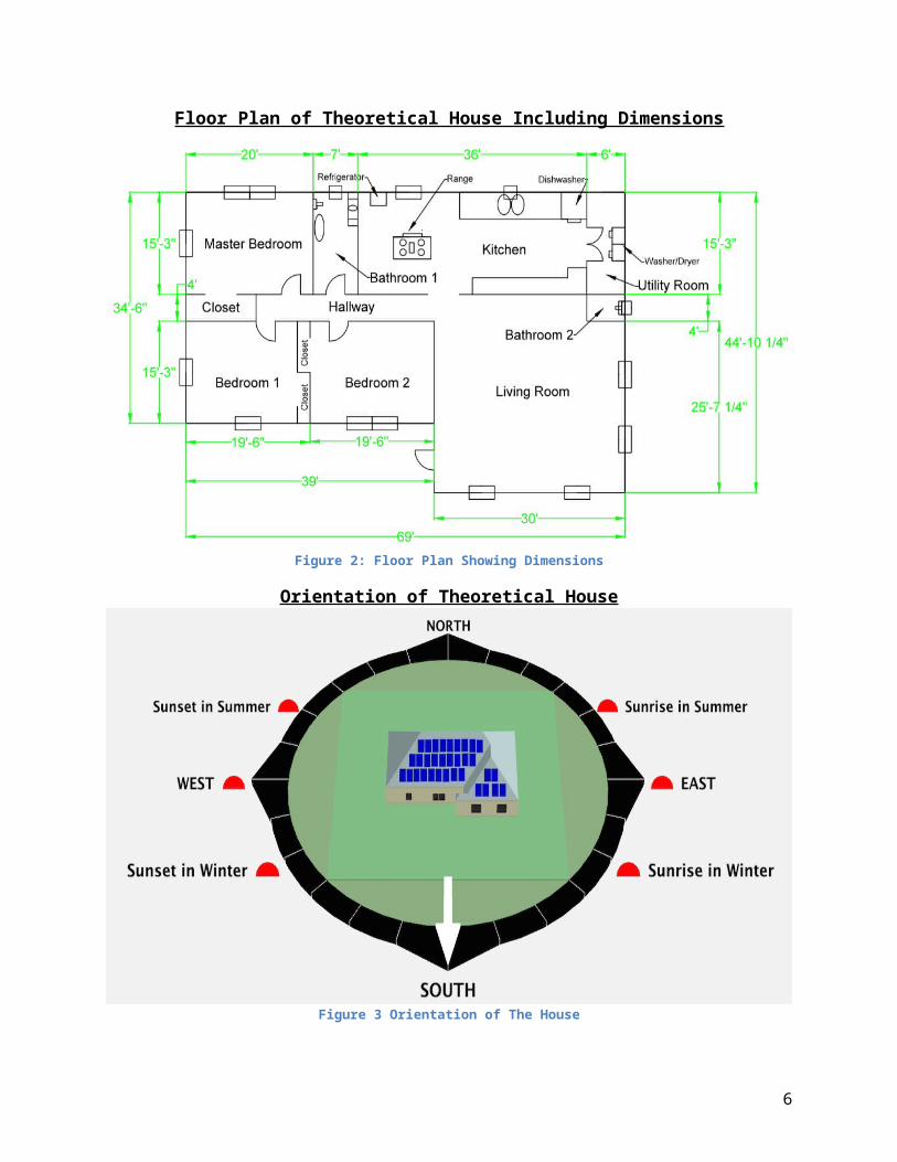
For this project, the location of the house to be designed and analyzed is in Islip Long Island, New York. The house was designed to accommodate four people and it consists of three bedrooms, one kitchen, one living room, and one and a half bathrooms. The house orientation is placed towards the south in order to achieve maximum solar gain. Thus, the side of the roof with the maximum area is also placed due south to accommodate the maximum amount of solar panels. The layout and orientation of the house can be found below:
Floor Plan of Theoretical House
Figure 1: Floor Plan
4

Floor Plan of Theoretical House Including Dimensions
Figure 2: Floor Plan Showing Dimensions
Orientation of Theoretical House
Figure 3 Orientation of The House
5
Construction
General construction design elements can be found in the table below:
General Design Parameters of Theoretical House
Table 1: Construciton Dimensions
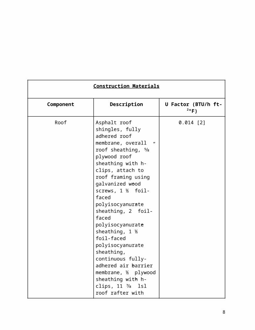
When determining the construction of the roof, walls, and floor a case study was referenced in which the challenges of creating a residential net zero energy home was explored. A table detailing the house’s construction can be found below:
6

Construction Materials
Component Description U Factor (BTU/h ft2°F)
Roof Asphalt roof shingles, fully adhered roof membrane, overall roof sheathing, ⅝” plywood roof sheathing with h-clips, attach to roof framing using galvanized wood screws, 1 ½” foil-faced polyisocyanurate sheathing, 2” foil-faced polyisocyanurate sheathing, 1 ½” foil-faced polyisocyanurate sheathing, continuous fully-adhered air barrier membrane, ½” plywood sheathing with h-clips, 11 ⅞” lsl roof rafter with cellulose cavity insulation, ½” gwb seams taped, painted with latex paint.
0.014 [2]
Exterior Walls Fiber cement siding, ¾” wd furring strip, 2 layers 2” foil-faced polyisocyanurate rigid insulation, joints staggered horizontally and vertically, outer layer sealed with tape, continuous fully-adhered air barrier membrane, ½” plywood sheathing, 2x6 24” o.c. wood stud wall with cellulose cavity insulation, ½” gwd painted with latex paint.
0.022 [2]
Windows Clear triple-pane ¼ inch glass with insulated krypton gas. SHGC=0.27[12]
0.242(5’x 5’)0.256(3’x 4’)0.261(3’x 3’)
Floor 4” on-grade concrete slab with w1.4 x w1.4 welded wire mesh placed at mid-depth, embedded hydronic tubing, 6 mil polyethylene vapor
0.313 [2]
7
barrier, 2” xps rigid foam slab insulation, 4” gravel pad, filter fabric, undisturbed native soil.
Door Insulated steel slab with wood edge in wood frame.
0.16 [12]
Table 2: Construction Materials and U-Values
Detailed elements of the windows and door can be found below:
Detailed Elements of All Windows and Doors
In order to maximize energy saving capabilities an extremely tight air sealed envelope was assumed. In reality this requires stringent construction procedures.
Infiltration Calculation
Infiltration in Winter Tight construction house with no leakage; No obstructions or local shielding
89.61 CFM
Infiltration in Summer Tight construction house with no leakage; No obstructions or local shielding
43,89 CFM
Table 4: Infiltration in the Summer and Winter
In calculating the infiltration, the following equation was used:
Table 3: Dimensions of Windows and Doors
8

Where AL = AesAul
Aul = 0.01 in2/ft2 in a tight construction supervised by an air sealing specialist
Aes = 4779 ft2 (area of the exposed building)ΔTsummer = 11.6 FΔTwinter = 55.9 FCs = 0.0150 CFM2/ (in4 F)Cw = 0.0119 CFM2/ (in4 mph) – building located in an area without obstructionsVw = 15mph in winter and 7.5 in summer
From table 4 above, it can be noted that the infiltration during the summer (43.89 CFM) is less than the infiltration during the winter (89.61 CFM).
Ventilation
Using ASHRAE 62.2 the ventilation requirements for the entire building can be calculated:
Qfan=0.01× A floor+7.5× (N bedrooms+1 )56.91 (cfm )=0.01×2691+7.5×(3+1)
It is noted that ASHRAE 62.2 requires additional airflow to meet local ventilation requirements. These local ventilation requirements are necessary for kitchens and bathrooms. In this basic analysis these local ventilation requirements will be omitted due to the capabilities of HEED. Continuous fan-forced fresh air ventilation was chosen to meet ASHRAE standards for the house. In addition to this a Heat Recovery Ventilator (HRV) system was incorporated into the ventilation system in order to reach maximum energy efficiencies. A 95% efficient HRV system was chosen for this application. Specification of the HRV unit can be found in the table:
General Information of HRV Unit
HRV Unit Airflow Capacity (cfm) Efficiency (%)Zehnder Novus 300 177 95
Table 5: Heat Recovery Ventilation
Below one can find several images of the house with different orientations:
9

View 1 of Theoretical House
Figure 4: Front View of the House (South)
10

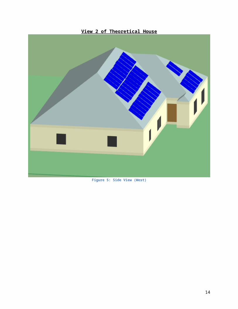
View 2 of Theoretical House
Figure 5: Side View (West)
11

View 3 of Theoretical House
Figure 6: Rear View (North)
12

View 4 of Theoretical House
Figure 7: Side View (East)
Appliances
Description of Appliances
Appliance Power Rating (V)
Efficiency Usage Load Factor
GE Profile Series 27.7 cu. ft. French Door- Refrigerator
120 Meets Energy Star Efficiencies
Continuous n/a
Samsung Chef Collection 30 in. 5.8 cu. ft. Range
220-240 n/a 3 days per week (2 hour period)
n/a
13
Samsung 5.6 cu. ft. Front Load Washer
120 Meets Energy Star Efficiencies
6 loads per week n/a
Samsung 7.4 cu. ft. Electric Front Load Dryer
220-240 Meets Energy Star Efficiencies
6 loads per week n/a
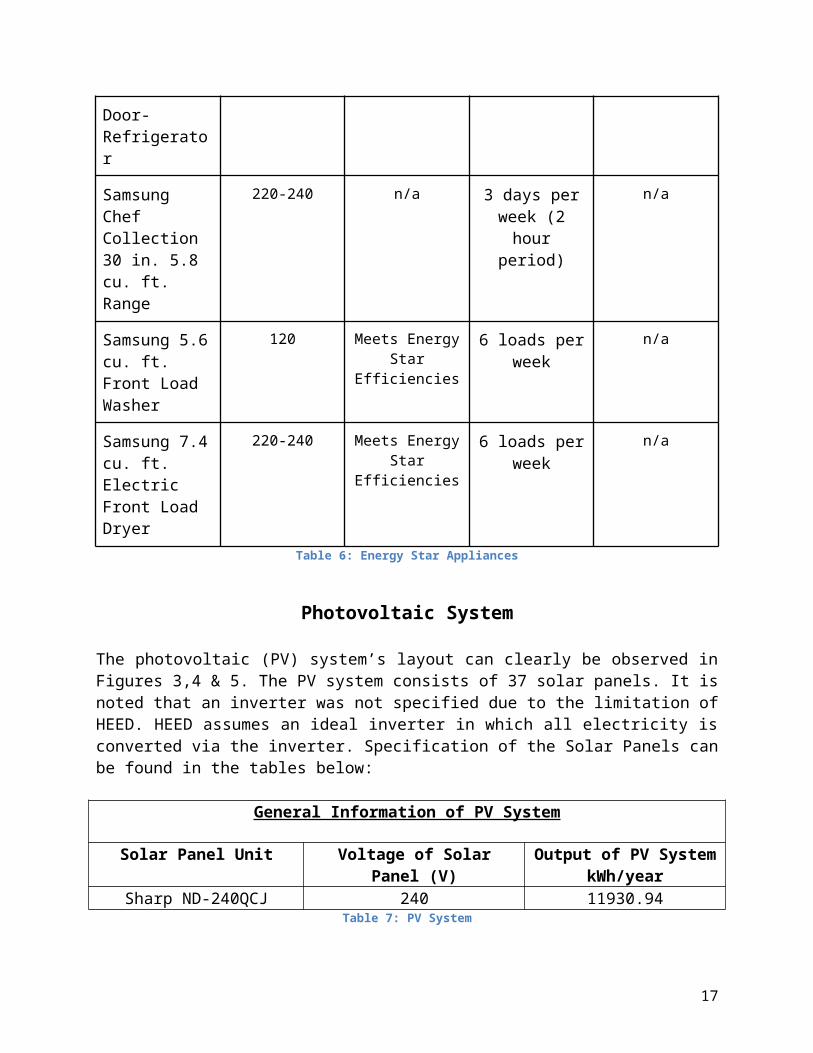
Table 6: Energy Star Appliances
Photovoltaic System
The photovoltaic (PV) system’s layout can clearly be observed in Figures 3,4 & 5. The PV system consists of 37 solar panels. It is noted that an inverter was not specified due to the limitation of HEED. HEED assumes an ideal inverter in which all electricity is converted via the inverter. Specification of the Solar Panels can be found in the tables below:
General Information of PV System
Solar Panel Unit Voltage of Solar Panel (V) Output of PV System kWh/year
Sharp ND-240QCJ 240 11930.94Table 7: PV System
Detailed Information of PV System
Table 8: PV System Specifications
U-Factors
As mentioned previously the lowest indoor design comfort temperature was set to be 68°F. The highest indoor design comfort temperature was set to be 75°F. The ground reflectance was assumed to be 0.2 year round. All ductwork for the heating/cooling system was placed inside the building envelope in order to limit losses to the outside environment. In addition, ductwork was insulated with cellulose in order to keep heated/cooled air at desired comfort conditions until reaching appropriate zones. Heating/cooling process is controlled by a smart thermostat, which enables energy savings by applying conditioned air during specific appropriate times. Furthermore, natural cooling can be enabled by manually opening windows and doors when
14

outside air is below the designed indoor comfort high temperature. By considering all these factors heating and cooling loads were generated:
Cooling and Heating Load Values
Table 9: Heating and Cooling Loads
From Table 9 above, the heating system size for the house (-13,894Btu/hr) is stated. This shows the amount of heat required to keep the house comfortable on its coldest night with no internal loads. It is calculated from steady state heat flow through the entire building envelope components plus the makeup air required for what is lost through infiltration and ventilation. Furthermore, it was assumed that the outdoor air temperature was at its winter design low and the indoor air was at its indoor comfort low.
On the other hand, the cooling system size (10,437 Btu/hr) is found by simulating the performance of the building as designed for every hour of the year, then finding the maximum cooling system demand when the outdoor air temperature is at its summer design high.
With the heating/cooling loads determined an appropriate heating/cooling device could be selected. A heat pump was chosen to handle heating/cooling loads in the house because of its extremely high capability for efficiency. Details of the chosen heat pump can be found below:
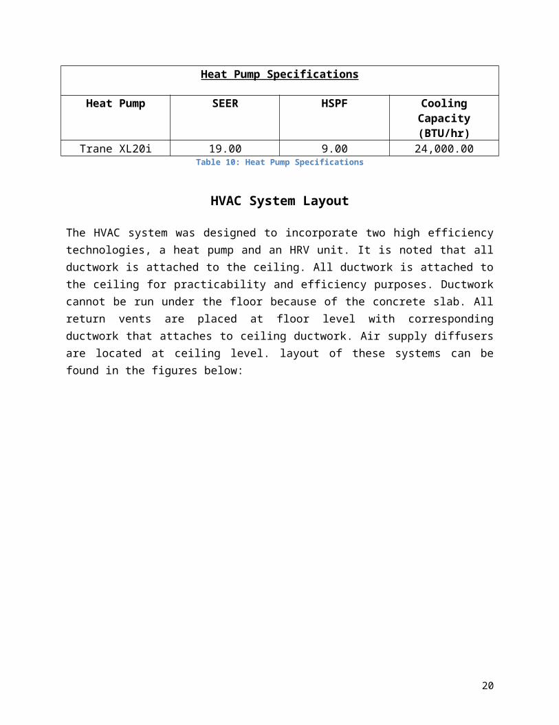
Heat Pump Specifications
Heat Pump SEER HSPF Cooling Capacity (BTU/hr)
Trane XL20i 19.00 9.00 24,000.00Table 10: Heat Pump Specifications
15

HVAC System Layout
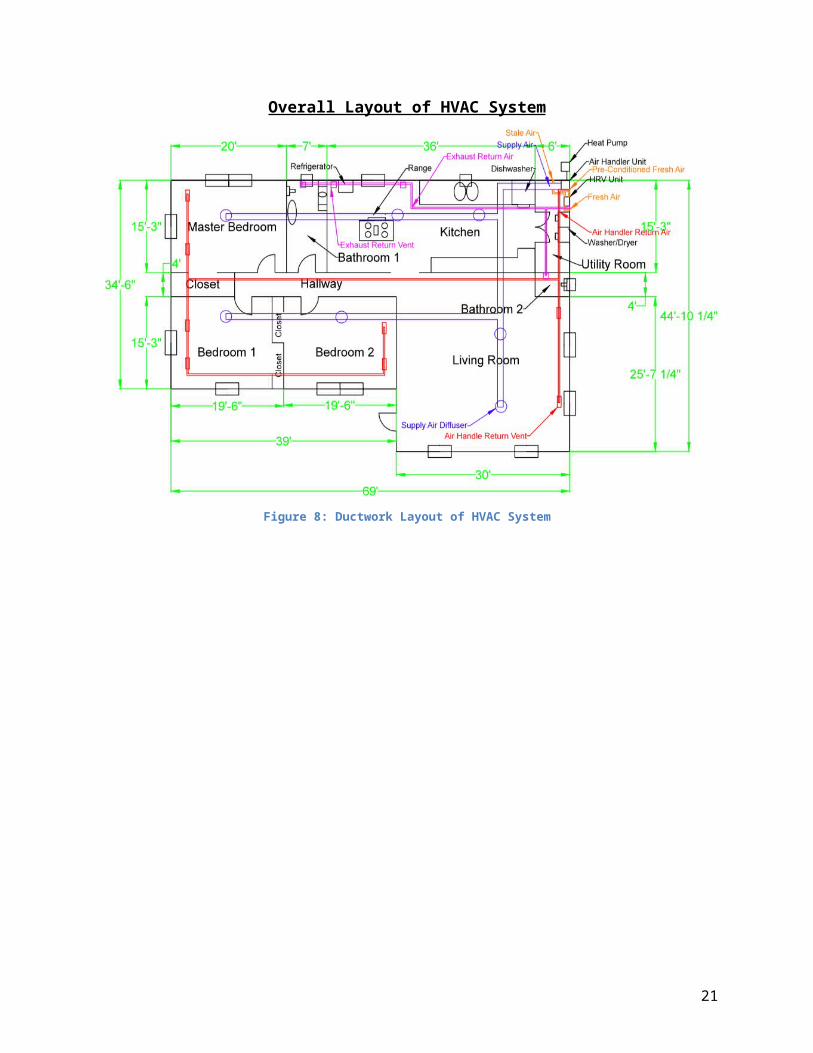
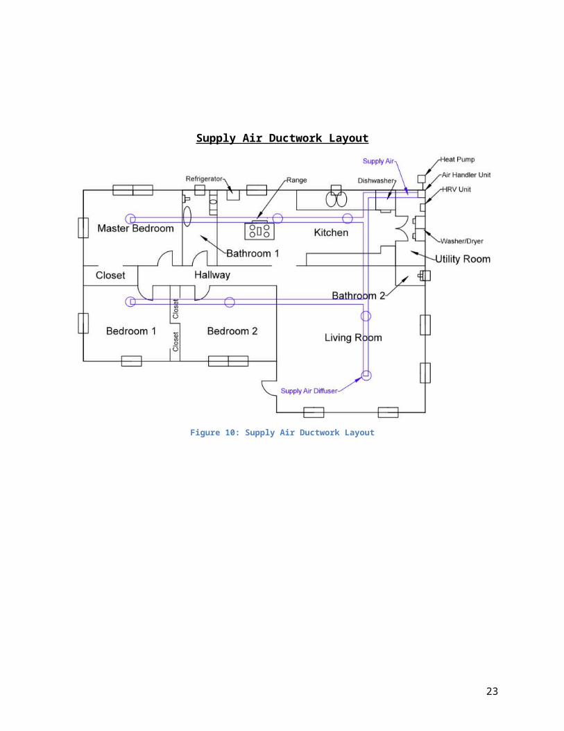
The HVAC system was designed to incorporate two high efficiency technologies, a heat pump and an HRV unit. It is noted that all ductwork is attached to the ceiling. All ductwork is attached to the ceiling for practicability and efficiency purposes. Ductwork cannot be run under the floor because of the concrete slab. All return vents are placed at floor level with corresponding ductwork that attaches to ceiling ductwork. Air supply diffusers are located at ceiling level. layout of these systems can be found in the figures below:
Overall Layout of HVAC System
Figure 8: Ductwork Layout of HVAC System
16
Heat Pump, Air Handler Unit, and HRV Unit Layout
Figure 9: Heat Pump, Air Handler and HRV Unit Ductwork Layout
17

Supply Air Ductwork Layout
Figure 10: Supply Air Ductwork Layout
18

Return Air Ductwork Layout
Figure 11: Return Air Ductwork Layout
19
Exhaust Return Air Ductwork Layout
Figure 12: Exhaust Air Ductwork Layout
20
Conclusion
Ultimately, a beyond net zero house was successfully modeled. The house produced 3,239 kWh/year of electricity while additionally meeting all of the homes required energy needs. The overall results can be found in Figure 13. It is noted that the first and second bars on Figures 13 and 14 represent early house designs. The third bar represents the most current home design.
Energy Consumption Per Year
Figure 13: Energy Consumption Per Year (Third Bar Represents Designed House)
Breakdown of Energy Consumption Per Year
Figure 14: Breakdown of Energy Consumption Per Year (Third Bar Represents Designed House)
21

Building Energy Performance Standards
Table 11: Energy Performance Standards of Designed House
Attached one can find an excel spreadsheet which contains all energy performance data of the designed house. This excel file is named “Performance Data”.
22
References1) Milne, Murray. "HEED: Home Energy Efficient Design." HEED: Home Energy Efficient Design. Accessed May 11, 2015. http://www.energy-design-tools.aud.ucla.edu/heed/.2) Pettit, Betsty, and Cathy Gates. "Design Challenges of the NIST Net Zero Energy Residential Test Facility." Building Science. 2014. Accessed May 11, 2015. http://www.buildingscience.com/documents/reports/rr-1401-design-challenges-nist-net-zero-energy-residential-test-facility.3) Hoellwarth, Craig. "Indoor Ventilation Minimum Best Practices Guide." California Energy Commission. 2008. Accessed May 11, 2015. http://www.energy.ca.gov/2010publications/CEC-400-2010-006/CEC-400-2010-006.PDF.4) "Retrofit Measures for." NREL: National Residential Efficiency Measures Database -. Accessed May 11, 2015. http://www.nrel.gov/ap/retrofits/measures.cfm?gId=12&ctId=216.5) "SUNNY BOY 240 US." SUNNY BOY 240-US. Accessed May 11, 2015. http://www.sma-america.com/products/solarinverters/sunny-boy-240-us.html.6) "Heat and Energy Recovery Ventilation Units (HRVs, ERVs) | Zehnder." Heat and Energy Recovery Ventilation Units (HRVs, ERVs) | Zehnder. Accessed May 11, 2015. http://zehnderamerica.com/products/heat-and-energy-recovery-ventilation-units/.7) "XL20i." Trane-Residential. Accessed May 11, 2015. http://www.trane.com/residential/en/products/heating-and-cooling/heat-pumps/xl20i.html.8) "WF9100 5.6 Cu. Ft. Front Load Washer with SuperSpeed (Onyx)." Samsung Electronics America. Accessed May 11, 2015. http://www.samsung.com/us/appliances/washers-dryers/WF56H9100AG/A2.9) "DV7770 7.4 Cu. Ft. Large Capacity (Electric) Front Load Dryer with Vent Sensor (Stainless Platinum)." Samsung Electronics America. Accessed May 11, 2015. http://www.samsung.com/us/appliances/washers-dryers/DV48J7770EP/A2.10) "Samsung Chef Collection 30 In. 5.8 Cu. Ft. Slide-In Flex Duo Electric Induction Range with Convection Oven in Stainless Steel-NE58H9970WS - The Home Depot." The Home Depot. Accessed May 11, 2015. http://www.homedepot.com/p/Samsung-Chef-Collection-30-in-5-8-cu-ft-Slide-In-Flex-Duo-Electric-Induction-Range-with-Convection-Oven-in-Stainless-Steel-NE58H9970WS/205469130?N=5yc1vZc3ob#specifications.11) "GE PROFILE™ SERIES ENERGY STAR® 27.7 CU. FT. FRENCH-DOOR REFRIGERATOR PFE28RSHSS." GE Appliances. Accessed May 11, 2015. http://products.geappliances.com/ApplProducts/Dispatcher?REQUEST=SpecPage&Sku=PFE28RSHSS.12) Naraghi, Mohammad. Energy Dynamics of Green Buildings. Hoboken, New Jersey: John Wiley & Sons, 2015.
23


