Embed Size (px)
Citation preview

GREEN AVIATION
PROPULSION SYSTEM CHALLENEGES & SOLUTIONS
Jayant Sabnis
Chief, System Functional Design
Pratt & Whitney
NASA Green Aviation Summit
September 8-9, 2010
Mountain View, CA
© 2010 United Technologies Corporation. All rights reserved. No part of this publication may be
reproduced, stored in a retrieval system or transmitted, in any form or by any means, electronic,
photocopying, recording or otherwise without the prior written permission of the copyright owners
Powering Change

Powering Change
•
–
–
–
•
–
–
–
•
© 2010 United Technologies Corporation.Subject to restrictions on the title page
PROPULSION SYSTEM REQUIREMENTSNoise And Fuel Burn Reduction
Reduced Fuel Burn
Reduced TSFC
Reduced Propulsion System Weight
Reduced Propulsion System Drag
Reduced Propulsion System Noise
Lower Jet Velocity
Lower Fan Tip speed
Lower Turbine Noise
Reduced Emissions
2

Powering Change
Com
bust
or
Jet
Eng
ine
Tota
l
Airc
raft
Tota
l
Turb
ine
Com
pres
sor
Fan
ENGINE SOURCE NOISE COMPONENTS
© 2010 United Technologies Corporation.Subject to restrictions on the title page
Fan and Jet Mixing Noise Are the Dominant Engine Sources
Fan Noise ~ V 5tip Jet Noise ~ Vjet6
Airf
ram
e5 dB
Com
bust
or
Jet
Eng
ine
Tota
l
Airc
raft
Tota
l
Airf
ram
e
Turb
ineC
ompr
esso
Fan
5 dB
Low Noise Requires Low Jet Velocity (hence Low FPR) anr d Low Fan Tip Speed
Typical Takeoff Distribution(Fan, Jet)
Typical Approach Distribution(Fan, Turbine, Airframe)
3

Powering Change
FUNDAMENTAL PROPULSION SYSTEM CHARACTERISTIC
© 2010 United Technologies Corporation.Subject to restrictions on the title page
Fuel Burn Reduction And Noise Reduction At Conflict With Each Other!
Fuel Burn
Fan Diameter
Noise
(Higher FPR) (Lower FPR)
Low
High
State-of-
The-ArtNoise
Fuel
Burn Advanced
Components
A380 Engines
4

Powering Change
FUNCTIONAL DESIGN CHALLENGE
Reducing Fuel Burn AND Noise

Powering Change
•
FUNCTIONAL ELEMENTS OF AIRCRAFT ENGINE
Propulsor, Gas Generator & Power Turbine
PROPULSOR (PR)
– Produce Thrust from Shaft Power (By Pushing on Air)
aka Fan / Propeller / Air Screw / Prop Fan / UDF / Open Rotor–
• POWER PLANT
– Produce Shaft Power from Chemical Fuel Energy
GAS GENERATOR (GG)
o “Heat Engine” to Convert Fuel Energy into Fluid Power
Delivers High-Pressure, High Temperature Gas (Drives PT)o
POWER TURBINE (PT)
o Convert Fluid Power to Mechanical (Shaft) Power
Drives Propulsoro
© 2010 United Technologies Corporation.Subject to restrictions on the title page
6
Powering Change
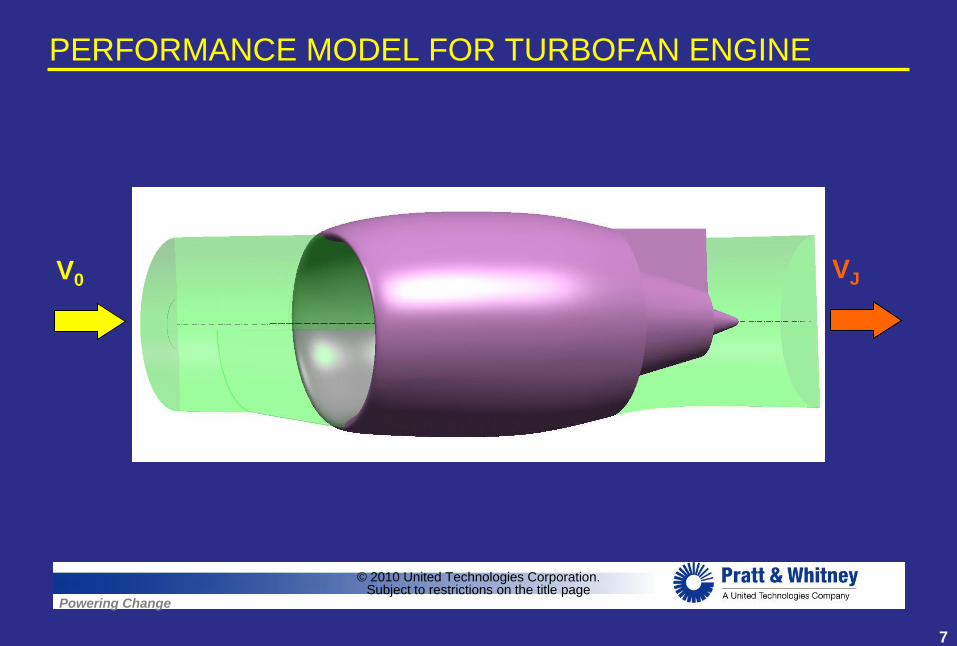
PERFORMANCE MODEL FOR TURBOFAN ENGINE
© 2010 United Technologies Corporation.Subject to restrictions on the title page
V0 VJ
7

Powering Change
PERFORMANCE MODEL FOR TURBOFAN ENGINE
Three-Step Power Conversion Process
• Step 1 : Gas Generator (GG)– Convert Ambient Air Into High-Pressure High-Temperature Gas
Thermal Efficiency (ηth = GG Power / Fuel Heat Release)–
© 2010 United Technologies Corporation.Subject to restrictions on the title page
8
Powering Change
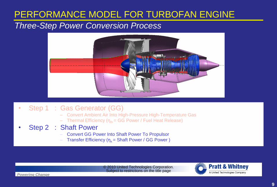
PERFORMANCE MODEL FOR TURBOFAN ENGINE
Three-Step Power Conversion Process
• Step 1 : Gas Generator (GG)– Convert Ambient Air Into High-Pressure High-Temperature Gas
– Thermal Efficiency (ηth = GG Power / Fuel Heat Release)
• Step 2 : Shaft Power– Convert GG Power Into Shaft Power To Propulsor
Transfer Efficiency (ηx = Shaft Power / GG Power )–
© 2010 United Technologies Corporation.Subject to restrictions on the title page
9
Powering Change
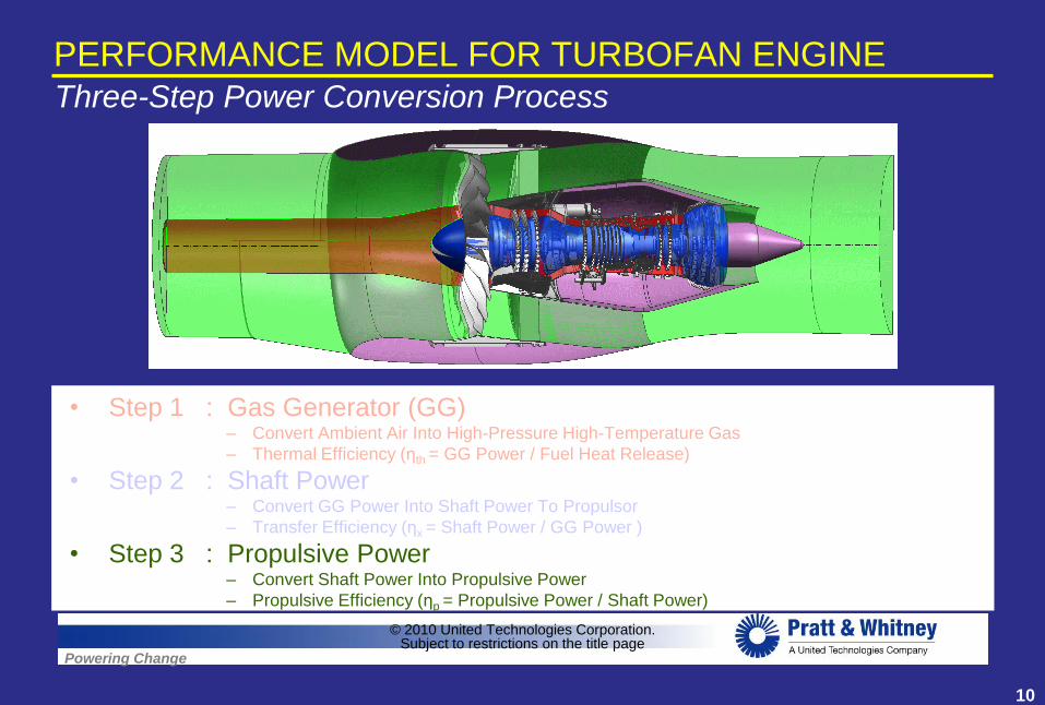
PERFORMANCE MODEL FOR TURBOFAN ENGINE
Three-Step Power Conversion Process
• Step 1 : Gas Generator (GG)– Convert Ambient Air Into High-Pressure High-Temperature Gas
– Thermal Efficiency (ηth = GG Power / Fuel Heat Release)
• Step 2 : Shaft Power– Convert GG Power Into Shaft Power To Propulsor
– Transfer Efficiency (ηx = Shaft Power / GG Power )
• Step 3 : Propulsive Power– Convert Shaft Power Into Propulsive Power
Propulsive Efficiency (ηp = Propulsive Power / Shaft Power)–
© 2010 United Technologies Corporation.Subject to restrictions on the title page
10

Powering Change
PERFORMANCE MODEL FOR TURBOFAN ENGINE
© 2010 United Technologies Corporation.Subject to restrictions on the title page
Three-Step Power Conversion Process
= X X
o TH X P
=
Overall
Efficiency
Thermal
Efficiency
Transfer
Efficiency
Propulsive
Efficiency
GG Power
Fuel Heat Release
Shaft Power
GG Power
Propulsive Power
Shaft Power
11

Powering Change
0.65
0.7
0.75
0.8
0.85
0.9
0.95
1
1 1.1 1.2 1.3 1.4 1.5 1.6 1.7FPR
Fa
n P
rop
uls
ive
Eff
icie
nc
y
M0 = 0.80
fan
Nfan
PfanSHP
VF 0
PROPULSIVE EFFICIENCY FOR FAN BYPASS SYSTEM
Ideal Fan P is Only a Function of FPR
and Flight Speed
© 2010 United Technologies Corporation.Subject to restrictions on the title page
12

Powering Change
0.65
0.7
0.75
0.8
0.85
0.9
0.95
1
1 1.1 1.2 1.3 1.4 1.5 1.6 1.7FPR
Fa
n P
rop
uls
ive
Eff
icie
nc
y
M0 = 0.80
PROPULSIVE EFFICIENCY FOR FAN BYPASS SYSTEM
Ideal Fan P is Only a Function of FPR
and Flight Speed
© 2010 United Technologies Corporation.Subject to restrictions on the title page
Internal Losses
in Fan Stream
fan
Nfan
PfanSHP
VF 0
13

Powering Change
0.65
0.7
0.75
0.8
0.85
0.9
0.95
1
1 1.1 1.2 1.3 1.4 1.5 1.6 1.7FPR
Fa
n P
rop
uls
ive
Eff
icie
nc
y
M0 = 0.80
PROPULSIVE EFFICIENCY FOR FAN BYPASS SYSTEM
Ideal Fan P is Only a Function of FPR
and Flight Speed
© 2010 United Technologies Corporation.Subject to restrictions on the title page
Internal Losses
in Fan Stream
fan
Nfan
PfanSHP
VF 0
14

Powering Change
0.65
0.7
0.75
0.8
0.85
0.9
0.95
1
1 1.1 1.2 1.3 1.4 1.5 1.6 1.7FPR
Fa
n P
rop
uls
ive
Eff
icie
nc
y
M0 = 0.80
PROPULSIVE EFFICIENCY FOR FAN BYPASS SYSTEM
Ideal Fan P is Only a Function of FPR
and Flight Speed
© 2010 United Technologies Corporation.Subject to restrictions on the title page
Internal Losses
in Fan Stream
fan
Nfan
PfanSHP
VF 0
15

Powering Change
0.65
0.7
0.75
0.8
0.85
0.9
0.95
1
1 1.1 1.2 1.3 1.4 1.5 1.6 1.7FPR
Fa
n P
rop
uls
ive
Eff
icie
nc
y
M0 = 0.80
PROPULSIVE EFFICIENCY FOR FAN BYPASS SYSTEM
Ideal Fan P is Only a Function of FPR
and Flight Speed
© 2010 United Technologies Corporation.Subject to restrictions on the title page
Internal Losses
in Fan Stream
fan
Nfan
PfanSHP
VF 0
16

Powering Change
0.65
0.7
0.75
0.8
0.85
0.9
0.95
1
1 1.1 1.2 1.3 1.4 1.5 1.6 1.7FPR
Fa
n P
rop
uls
ive
Eff
icie
nc
y
M0 = 0.80
PROPULSIVE EFFICIENCY FOR FAN BYPASS SYSTEM
Ideal Fan P is Only a Function of FPR
and Flight Speed
© 2010 United Technologies Corporation.Subject to restrictions on the title page
Internal Losses
in Fan Stream
Aim to Achieve the Propulsive Efficiency
Benefit of Turboprop and Noise Benefit of Turbofan
fan
Nfan
PfanSHP
VF 0
17

Powering Change
0
0.1
0.2
0.3
0.4
0.5
0.6
0.7
0.8
0 10 20 30 40 50 60 70
Cycle
Th
erm
al
Eff
icie
ncy
OPR
T4/T2 = 8.0
T4/T2 = 5.0
Ideal Cycle
GAS GENERATOR THERMAL EFFICIENCYHigh Th High OPR, High T4.1 & Low-Loss Turbomachinery
Thermal Efficiency Improvements are Reaching Point of Diminishing Returns
© 2010 United Technologies Corporation.Subject to restrictions on the title page
18
Powering Change
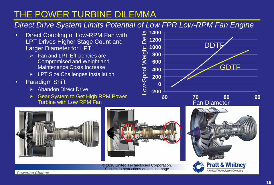
THE POWER TURBINE DILEMMADirect Drive System Limits Potential of Low FPR Low-RPM Fan Engine
Direct Coupling of Low-RPM Fan with LPT Drives Higher Stage Count and Larger Diameter for LPT.
Fan and LPT Efficiencies are Compromised and Weight and Maintenance Costs Increase
LPT Size Challenges Installation
Paradigm Shift
Abandon Direct Drive
Gear System to Get High RPM Power Turbine with Low RPM Fan Fan Diameter
•
•
© 2010 United Technologies Corporation.Subject to restrictions on the title page
Lo
w-S
poo
l W
eig
ht D
elta
DDTF
60 70 80 90
1400
1200
1000
800
600
400
200
0
-200
GDTF
19

Powering Change
POWER TURBINE / TRANSFER EFFICIENCYHigh-Speed Power Turbine Enables Installation, Low Weight & High Efficiency
Direct-Drive
LPT
High-Speed LPT
Dh/U2
1.5 %
Direct-Drive
LPT
L
PT
© 2010 United Technologies Corporation.Subject to restrictions on the title page
2
3
4
5
6
7
8
9
10
1.2 1.3 1.4 1.5 1.6 1.7
SAI DDTF
SAI GDTF
DDTF
GDTFSta
ge
Co
un
t
1.2 1.3 1.4 1.5 1.6 1.7FPR
10
9
8
7
6
5
4
3
2
0.3
0.35
0.4
0.45
0.5
0.55
0.6
0.65
1.2 1.3 1.4 1.5 1.6 1.7
DL
PT/D
FA
N
DDTF*
GDTF
Source:
Flowpath: Janes
FPR: PW est.
1.2 1.3 1.4 1.5 1.6 1.7FPR
0.65
0.60
0.55
0.50
0.45
0.40
0.35
0.30
20

Powering Change
FUNDAMENTAL PROPULSION SYSTEM CHARACTERISTIC
© 2010 United Technologies Corporation.Subject to restrictions on the title page
Gear Driven Propulsor Enables Improved Fuel Burn AND Lower Noise
Fuel Burn
Fan Diameter
Noise
(Higher FPR) (Lower FPR)
Low
High
State-of-
The-ArtNoise
Fuel
Burn Advanced
Components
Increasing weight of Low-RPM
LPT contributes to increasing
fuel burn
Paradigm
Shift
Noise
Reduction
Fuel Burn
Reduction
21

Powering Change
•
CHALLENGES AND OPPORTUNITIESLow Pressure Ratio Propulsors Present New Opportunities
Characterize Performance of Low Pressure Ratio Propulsors
– Efficiency, Noise, Distortion Tolerance
• Installation Challenges
– Propulsion system / Aircraft Interaction
• Novel Installation Concepts
• Novel Aircraft Configuration
– Embedded Installation
• Rig / Wind Tunnel Experiments
• System Demonstrators
© 2010 United Technologies Corporation.Subject to restrictions on the title page
22