Embed Size (px)
Citation preview

GReddy Turbo Kit
Honda Civic Si EP3 (K20A) T517Z 8cm2
Honda Civic Si EP3 (K20A) T517Z 8cm2
Installation Manual
Please read the entire manual before installing this kit. Application: Make Model Chassis Year Honda Civic EP3 EP3 02~03
• This GReddy Turbo Kit Is designed only for the vehicles specified above.
• GReddy Front mount intercooler kit is recommended with this kit. (Please check with your GReddy Authorized dealer for availability)
• Premium grade gasoline (92 octane or higher) is required with this Kit.
• Make sure that the vehicle is not equipped with any ECU upgrade chips.
• Use of GReddy Racing Spark Plugs ISO #7 or NGK plugs (colder than factory)
is recommended with this kit. Important
• This installation should only be performed by a trained specialist who is very familiar with the automobile’s mechanical, electrical and fuel management system.
• If installed by an untrained person, it may cause damage to the kit as well as the vehicle.
• GReddy Performance Products Inc. is not responsible for any damage to the vehicle’s electrical system caused by improper installation.

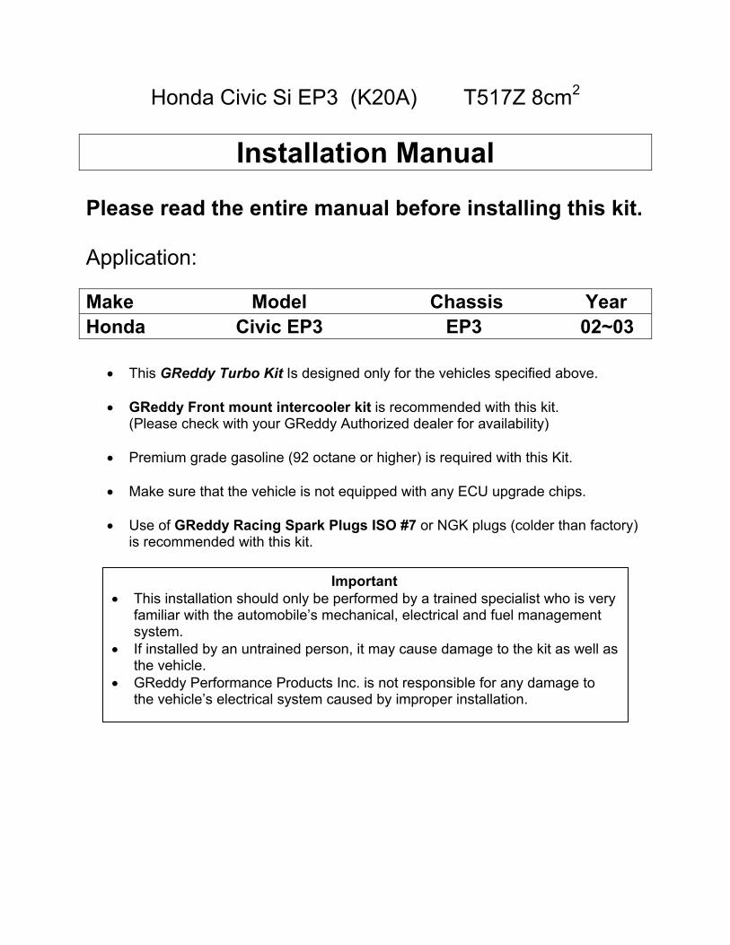
1. Parts List 1. Turbocharger T517Z 8cm2 P565 1
2. Turbo Exhaust Manifold (Cast Iron) 1
3, Down Pipe Adapter (Cast Iron-Steel 60∅) 1
4. Suction Pipe (Aluminum 60Ø) 1
5. TZ suction flange (Aluminum 60Ø) 1
6. Compression Pipe C-1 (Aluminum 50Ø) 1
7. “ C-2 (Aluminum 60Ø) 1
8. “ C-3 (Aluminum elbow No. 76 60Ø) 1
9. Restrictor (Aluminum 43∅) 1
10. Airinx AY-MB (Blue filter) 1
11. Airinx Adapter (M60) 1
12. Fuel Injector 440cc (w/spacerx2, stud bolt x2 o-ringx8) 4
13. “ Connector Harness 4
14. e-Manage 1
15. I/J Harness (18P) 1
16. Sensor Adapter Type-AII US 1
17. Oil Pressure Hose SUS 600mm 1
18. “ Banjo Fitting male & female (small) 1set
19. “ Copper Washer 10∅ (t=1.0mm) 2
20. “ Three Way Fitting 1
21. “ Union Fitting 1/8PT – 1/8 PT 1
22. “ Union Fitting 1/8PT – 1/8PF 90° 1
23. Oil Return Flange tube 16∅ (Turbo side) 1
24. “ Banjo Fitting male & female 16∅ (Engine side) 1Set
25. “ Banjo Spacer t=16 1
26. “ Banjo Copper washer 15.5∅ (t=1.0mm) 3

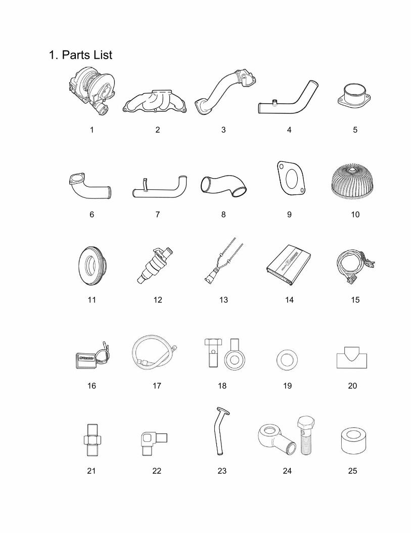
1. Parts List 27. Vacuum Hose (Blue) 5∅ x 200mm (for Actuator) 1
28. Rubber Hose 8Ø X 500mm (for Idle controller) 1
29. Rubber Hose 16Ø X 400mm (for Oil return) 1
30. Rubber Hose 19Ø X 190mm (for Blow by) 1
31. Silicone Hose 60Ø x70mm 2
32. Reducer Hose 50Ø – 60Ø 1
33. Reducer Hose 60Ø – 70Ø 1
34. Hose band 8Ø Tridon #4 2
35. Hose band 16Ø Tridon #10 2
36. Hose band 19Ø Tridon #12 2
37. Hose band 50Ø Tridon #32 1
38. Hose band 60Ø Tridon #36 7
39. Hose band 70Ø Tridon #44 1
40. Gasket Turbo in 2
41. Gasket Turbo in 1
42. Gasket Turbine in 1
43. Gasket Turbine out 1
44. Gasket Down Pipe 1
45. Gasket Oil Return Flange Tube Small 1
46. Heat Shield Turbine 1
47. Heat Shield Down pipe 1
48. Thermo-cloth 100mm X 1000mm sheet 4
49. Zip ties 150mm 10
50. Zip ties 200mm 5
51. Three-way Vacuum Tee 10∅-6∅-10∅ 1
52. Suction pipe bracket 1
53. Oil return hose bracket 1
54. Airinx hose fitting 8∅-M18 1
55. Intake Air Temperature Grommet 1

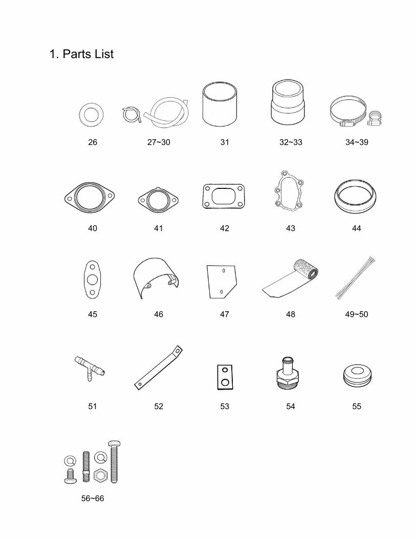
1. Parts List 56. M6 X 10 P=1.0 B S/W F/W - (Down pipe heat shield) 2
57. M6 X 15 P=1.0 B S/W F/W - (Suction pipe & compression pipe bracket) 2
58. M6 X 15 P=1.0 B S/W F/W N (Suction pipe bracket) 1
59. M6 X 15 P=1.0 B S/W - - (Oil Return Bracket) 2
60. M8 X 15 P=1.25 B S/W F/W - (Turbine heat shield) 2
61. M8 X 30 P=1.25 B S/W F/W N (Compressor inlet) 2
62. M8 X 20 P=1.25 B S/W F/W - (Compressor outlet) 2
63. M8 X 30 P=1.25 B S/W - N (Exhaust manifold – Turbo in flange) 7
64. M8 X 75 P=1.25 B S/W - - (Turbine out) 2
65. M8 P=1.25 - - - N (Down pipe) 2
66. M10 X 45 P=1.25 B S/W F/W N (Ex. Manifold) 3
1. Parts List
1 2 3 4 5
6 7 8 9 10
11 12 13 14 15
16 17 18 19 20
21 22 23 24 25
1. Parts List
26 27~30 31 32~33 34~39
40 41 42 43 44
45 46 47 48 49~50
51 52 53 54 55
56~66

2. Removal of Stock Parts
When removing the stock parts, make sure you read over the factory repair manual for proper procedures.
2-1 Disconnect the negative terminal of the battery. 2-2 Release the fuel pressure in the fuel system by loosening the fuel pulsation
damper on top of the fuel rail. (see factory repair manual for detail procedure). 2-3 Drain the engine oil. 2-4 Remove the front strut bar and it’s brackets. 2-5 Remove the engine cover.
2-6 Remove the Air cleaner assembly with intake tube, breather hose and Intake temperature sensor.
2-7 Disconnect the primary and secondary O2 sensor and remover the catalytic
converter.
2-8 Remover the VTEC solenoid valve assembly. 2-9 Remove the exhaust system heat shield and manifold. 2-10 Remove the heat shield plate (bottom of the firewall) and the intermediate drive
shaft heat shield.

3. Kit Installation 3-1 Factory heat shield modification
(1) Heat shield plate modification Trim the shaded area on the heat shield plate that was removed as shown.
(2) VTEC Solenoid Valve Assembly heat shield Modification. Trim the shaded area on the heat shield that was removed as shown.
3-2 Thermo Cloth Installation Power Steering Hose
Engine Harness
(1) Disconnect the Crank sensor and Oil Pressure Sensor connector and wrap the thermo cloth to the harness as shown.
(2) Wrap the thermo cloth to the power steering line by the fire wall. (3) Wrap the thermo cloth to the engine
harness and the heater hoses by the fire wall.

3-3 Oil Pressure Line Installation
Install the 3-way fitting to the block first.
3-way fitting
PF
PT PT PT
Oil Pressure Switch (1) Remove the Oil Pressure switch and
install the union fitting and 3-way fitting on to the block.
* Use Teflon tape on the thread. * Point the 3-way fitting outlet where the
oil pressure switch is going to be installed to 2 o’clock.
(Parts used #21,22,23)
(2) Install the oil pressure switch to the 3- way fitting and reinstall the VTEC solenoid assembly with the modified heat shield.
* Make sure that the heat shield does not hit the oil pressure switch.
Check (3) Reconnect the oil pressure switch
harness and the crank sensor.
(4) Connect the oil pressure line to the installed union fitting.
(Parts used #18)
3-4 Exhaust Manifold Installation (1) Install three stud bolt on to the cylinder
head as shown. (Parts used #67)

(2) Install the exhaust manifold using the
factory gasket. * Use a new exhaust manifold gasket. * Use factory nuts on the top side of the
flange. (Parts used #2, 67)
3-5 Turbocharger Installation
(1) Wrap the thermo cloth the actuator as shown.
* The heat off the manifold can damage the actuator with out the thermo cloth.
(2) Install stud bolts on to the exhaust manifold, then mount the turbocharger to the manifold using provided gasket.
(Parts used #1,43,64)
3-6 Oil Pressure Line Connection
(1) Connect the oil pressure line that was installed in step 3-4 to the turbo using banjo fitting and copper washers. As shown.
* Point the banjo fitting towards the firewall.
(Parts used #19,20)

3-7 Oil Return Installation
(1) Install the provided oil return pipe to the turbocharger using the provided gasket and hardware as shown.
(Parts used #24, 46, 60)
(2) Remove the oil drain bolt and install the provided oil return banjo bolt using spacer and copper washers as shown.
(Parts used #25, 26, 27)
(3) Wrap the provided 16∅hose with thermo cloth. Then Install the hose to connect the oil return pipe from the turbo to the oil return banjo fitting on the oil pan.
* Route the hose behind the intermediate drive shaft as shown.
(Parts used #30, 36, 49)
(4) Install the Oil return hose bracket to the block and secure the hose to the bracket using provided zip ties as shown.
(Parts used #50, 54)
(5) Modify the drive shaft heat shield by cutting the shaded area in the picture to prevent the hose from rubbing up on the shield.

• Reinstall the heat shield and make sure
there are enough clearance between the hose and the shield and the drive shaft. * Oil return hose to heat shield: 10mm * Oil return hose to drive shaft: 20mm
Important! With out this proper clearance, there is a possibility of the return hose to fail and can cause fire and damage the engine.
3-8 Compression Pipe Installation (1) Install Compression pipe C-1 to the out
let of the turbo using provided gasket and hardware.
(Parts used #6, 42, 63)
(2) Loosen the hose clamp on the Radiator hose and rotate the hose so it comes up slightly.
(3) Install compression pipe C-2, and C-3
between C-1 and throttle body. Using provided hose and clamps.
* Secure the bracket on C-2 to the factory air cleaner box mounting point.
* Make sure that the compression pipes does not interfere with shifter linkage movement. Also, check the clearance between the radiator hose and compression pipes.
(Parts used #7, 8,32, 33,34, 38,39, 40,58)

(4) Cut the master power vacuum hose by
the intake manifold and install the 3-way fitting. Connect the 5∅ side to the actuator with the provided 5∅ hose.
* Secure all the vacuum hose with zip ties to prevent the hose from coming off the fitting.
(Parts used #28,50,52)
3-9 Intake Pipe Installation
Hose Adapter
Tab
Main Body
(1) Remove the top bolt on the Airinx air filter and remove the outer frame.
(Parts used #10)
(2) Install the provided hose adapter to the
inner frame of the Airinx. (Parts used #11)
(3) Reinstall the outer frame and secure it
with the top bolt. (4) Remove the rubber plug on the Airinx
and install the union fitting as shown. (Parts used #55)
(5) Install the provided intake air
temperature sensor grommet to the suction pipe S-1 as shown.
IAT Sensor
Grommet
(Parts used #4, 56)

(6) Install stud bolts on to the inlet of the
turbo, and install suction adapter using provided gasket and restrictor.
(Parts used #5,9,41,62) Important!
The restrictor must be used with this turbo kit. With out it, the system can exceed the set boost level and can damage the engine.
(7) Install the Airinx air filter and S-1.
Secure the suction pipe bracket to the factory air cleaner box mounting point as shown.
S-1
Mounting point
* Make sure that the Airinx and the piping does rub up on to the battery.
(Parts used #32,39,53,58,59) (8) Connect the blow by tube from the valve
cover to the S-1 with the provided 18∅ hose and clamps. Also connect the Air assist control valve to Airinx using provided 8∅ hose and clamps.
Blow by hose
To air assist Control valve
(Parts used #29,31,35,37) 3-10 Down Pipe Installation (1) Install three stud bolt on the turbine
housing as shown. (Parts used #64)

(2) Check the fitment of the downpipe heat
shield and install gasket on the catalytic converter end of the downpipe.
* The heat shield will be reinstalled later once the downpipe is installed.
(Parts used #45, 48) (3) Install the downpipe to the turbo using
provided gasket and hardware. * Make sure that there are enough
clearance between the downpipe and the oil pressure line.
(Parts used #3,44,64,65) (4) Reinstall the catalytic converter and
reconnect the o2 sensor connectors. * Reuse factory hardware to bolt the cat
back on but the bolt with spring will require the provided nuts.
(Parts used #66) • Heat Shield Installation (1) Install the turbine housing heat shield on
to the downpipe using the provided M8 x 15mm bolts.
* Make sure that there are enough clearance between the oil pressure line and the power steering line.
(Parts used #47,61) (2) Install the down pipe heat shield on to
the downpipe using the provided M6 x 10mm bolts.
(Parts used #48,57)

3-12 Fuel Injectors Installation (1) Disconnect the fuel injector connectors
and ground wire on the fuel delivery tube and remove the fuel delivery tube.
* When removing the rail, use a rag to absorb the fuel that leaks out from the rail and hose.
(2) Remove the injector clips off the rail,
and remove the injectors. (3) Install the new injectors on to the rail. * Lube the o-rings on the injectors and
make sure not to damage the o-ring when installing them in to the rail.
(Parts used # 12) (4) Replace the stud bolts and spacers that
holds the fuel rail down with the provided stud bolts and spacers.
(5) Install the fuel rail assembly to the
intake manifold. (6) Remove the injector wire cover and cut
the factory injector connectors. Cut the provided injector harness to the same length of the cut factory connectors.
(Parts used # 13)
Soldered. Make sure the wires are properly
4. Tape up the exposed wires. 3.soldder the wires
2. Twist the two ends together. 1.Strip the wire ends.
How to Solder (7) Solder the connectors to the harness
and connect them to the injectors. Reconnect the ground wire back to the manifold.

3-13 e-Manage Installation
(1) Remove the cover under the glove box to access the ECU and ECU harness. (2) Install the Grey wire to the e-Manage I/J Harness (18Pin) connector as shown
below.
(3) Connect the I/J Harness to the factory ECU harness as shown in the diagram on next page.
(Parts used #15, 16, 17)
Important • This installation should only be performed by a trained specialist who is very
familiar with the automobile’s electrical and fuel management system. • GReddy Performance Products Inc. is not responsible for any damage to
the vehicle’s electrical system caused by improper installation. • It is recommended to solder all wires and use electrical tape or shrink warp
to insulate the wire connections.

86 4 2 7 3 7 9
10 13 115 6 18
4 23 222 225 6 29 31
1 2 3 4 5 6
8 10 4113 15 16
8 117 2221 23 24
1 2 3 4 5 6 7 9
11 110 2 16 15 29 118 20 1
23 223 4 6 225 227 28 0 39
Connector E (31P)
Connector D (17P)
Connector C (22P)
Connector B(24P)
Connector A (31P)
SLC (R)
スフ
A10
18-8 (PL/R)
18-7 (Y/R)
18-6 (O/R)
18-5 (B/R)
18-3 (W) 18-10 (G)
18-12 (B)
18-18 (B/R)
18-4 (GR)
18-13 (R)
SLC (B)
18-11 (BR)
A3
A15 A18
A19
A5 B2 B3
B4 B5
E26
SLC (BR) SLC (LB)
SLC (PL)
18-9 (PL)
Color Code: W - White, G - Green, B - Black, BL - Blue, BR - Brown, R - Red, GR - Grey, PL - Purple, Y - Yellow, O - Orange, LB - Light Blue

e-manage Factory ECU
Pin #
Wire Color Description ECU Pin # Color Code
3 White MAP IN A19 arness) Green/Red MAP (h
4 Grey Throttle A15 Red/Black TPS 5 Blue/Red INJ 1 B5 Brown INJ 1 6 Orange/Red INJ 2 B4 Red INJ 2 7 w/Red INJ 3 B3 Blue INJ 3 Yello
8 e/Red INJ 4 B2 Yellow INJ 4 Purpl
9 e PLS SLC Purple Purpl
10 Green MAP OUT
A19
(ECU side) Green/Red MAP
11 Brown RPM E26 Blue NEP 12 Black GND A5 Black PG1 13 Red +B A3 Yellow/Black IGP1 18 Black/Red INJ GND A5 Black PG1
Sens r Factory ECU or AdapteWire Color Description ECU Pin # Color Code
Blue (Male) SPD IN A18 (Harness) White/Green VSS Brown (female) SPDOUT A18(ECU side) White/Green VSS Purple (Male) PLS e-Manage 18-9 Purple Red +B A3 Yellow/Black IGP1
Black GND A10 Green/Yellow SG2
(5) Reinstall the ECU back in its place, and secure the e-Manage next to the ECU.
isture, or near heater outlet
* Looking at harness side.
I/J Harness (18Pin)
Important ! Make sure the all the wire connections are correct. If they are connected incorrectly, it can damage the e-Manage and/or the ECU.
* Avoid mounting the e-Manage unit in the area that would be exposed to direct sun light, mo

3-15 Starting the Engine (1) Refill the engine oil to factory spec. (2) Check all the hoses and wires ne then nect egative e of
the battery. (3) Tun the ignition to “ON” positio 3 get
injectors and the fuel rail for any fuel leaks. * Repair any fuel leaks before starting the engine. Starting the engine with a
fuel leak can cause fire in the engin nt and can bedangerous.
(4) Remove the ECM fuse and cra e to oil pre
(Until the oil light on the dash turns off) Check for any oil leaks, then reinstall the fuse and start the engine.
(5) While idling, check for any oil, coolant, or air leeks. (6) After inspection, reinstall the under cover and other stock parts that was
remove
) e turbo-actuator setting. This turbo kit is preset to boost between 0.6kg/cm2 to 0.5kg/cm2 .
This completes the Turbo Kit installation.
Important! • It is very important that you monitor the boost pressure, and make sure
not to over boost. Over boosting can cause engine damage. • GReddy Performance Products, Inc. is not responsible for any engine
damage caused by over boosting (increased boost), modification to the kit, and/or misuse of the product. NO WARRANTY is offered.
• Due to lack of control over proper installation and use of this product, his kit.
con ction, recon the n sid
n 2- times to fuel pressure. Then, check the
e compartme very
nk the engin get ssure to the turbo.
d. (7 On the initial run, be sure to have a boost gauge to check th
It is very important that you monitor the boost pressure, and make sure not to over boost. Over boosting can cause engine damage.
NO WARRANTY is offered for t
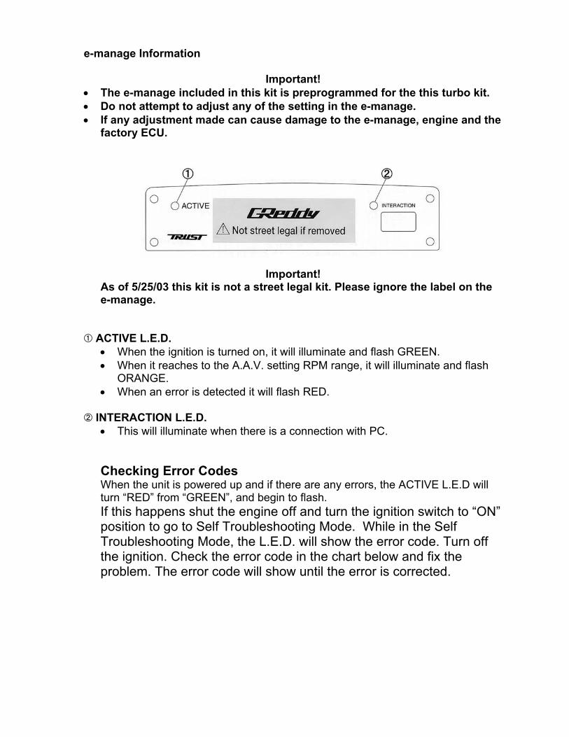
e-manage Information
Important! The e-manage included in this kit is preprogrammed for the this turbo kit. Do not attempt to adjust any of the setting in the e-manage.
the
As of 5/25/03 this kit is not a street legal kit. Please ignore the label on the e-manage.
ACTIVE L.E.D. • When the ignition is turned on ate and flash GREEN.
When an error is detected it will flash RED.
INTE•
Ch When the unit is powered up and if there are any errors, the ACTIVE L.E.D will
turn “RED” from “GREEN”, and begin to flash. If this happens shut the engine off and turn the ignition switch to “ON” position to go to Self Troubleshooting Mode. While in the Self Troubleshooting Mode, the L.E.D. will show the error code. Turn off the ignition. Check the error code in the chart below and fix the problem. The error code will show until the error is corrected.
••• If any adjustment made can cause damage to the e-manage, engine and
factory ECU.
Important!
, it will illumin• When it reaches to the A.A.V. setting RPM range, it will illuminate and flash
ORANGE. •
RACTION L.E.D. This will illuminate when there is a connection with PC.
ecking Error Codes

Checking Error Code Chart
CODE
Incorrect wiring or disconnected Airflow Signal 1input error11
15
Airflow Signal 1
No Injec
Airflow voltage
pulse from all
tor 1 pulse
No Injector 2 pulse
e
Incorrect Airflow signal output wiring.
signal forAdditional Injection Map
Not receiving injector signal I/J CH-1
Not receiving injector signal I/J CH-2 for Additional Injection Map
Not receiving injector signal I/J CH-3 for Additional Injection Map
20
22
40
41
42
43
44
51
52
53
54
57
Improper order of Ignition input signal
Error��� Error description
Incorrect wiring order of the ignition signal wires.
No Ignition Signal 1pulse
No Ignition Signal 2pulseNo Ignition Signal 3pulseNo Ignition Signal 4pulse
Not receiving the ignition signal to IG CH-1
Not receiving the ignition signal to IG CH-2
Not receiving the ignition signal to IG CH-3
Not receiving the ignition signal to IG CH-4
pulse
Incorrect Ignition 2 pulse Incorrect Ignition 3 pulse
Incorrect Ignition 4 pulse
JP2 + 12Verror
Incorrect IG CH-1 wire to e-Manage unit
Incorrect IG CH-2 wire to e-Manage unit
Incorrect IG CH-3 wire to e-Manage unit
Incorrect IG CH-4 wire to e-Manage unit
Incorrect Jumper setting (JP2)
Not receiving the ignition signal y of the channels
output errorNo Injector Not receiving an injector
for Additional Injection Map21
No Injector 3 puls23No Injector 4 pulse Not receiving injector signal I/J CH-4
for Additional Injection Map24
31
32
33
34
Incorrect Injector 1 pulse
Incorrect Injector 2 pulse Incorrect Injector 3 pulse
Incorrect Injector 4 pulse
Incorrect I/J CH-1 wire to e-Manage unit
Incorrect I/J CH-2 wire to e-Manage unit
Incorrect I/J CH-3 wire to e-Manage unit
Incorrect I/J CH-4 wire to e-Manage unit
49Incorrect Ignition 1
No Ignition pulse to an