Embed Size (px)
Citation preview
GReddy Turbo Kit
2003 Nissan 350Z (VQ35DE) Twin TD05-18G 8cm2

Installation Manual
Please read the entire manual before installing this kit.
Application:
Make Model Chassis Year
Nissan 350Z Z33 2003
• This GReddy Turbo Kit is designed only for the vehicles specified above. • GReddy Front mount intercooler kit is recommended with this kit • Premium grade gasoline (91 octane or higher) is required with this Kit. • Make sure that the vehicle is not equipped with any ECU upgrade chips. • Use of GReddy Racing Spark Plugs ISO LONG #7 or NGK plugs (colder than
factory) is recommended with this kit.
Important
1. This installation should only be performed by a trained specialist who is very familiar with the
automobile’s mechanical, electrical and fuel management system.
2. If installed by an untrained person, it may cause damage to the kit as well as the vehicle.
3. GReddy Performance Products Inc. is not responsible for any damage to the vehicle’s electrical
system caused by improper installation.
4. Make sure to follow the instruction and pay attention to the “Important”, “Warning!” and “Caution!”
notice through out the instruction.
5. Improper installation can be dangerous! Please make sure to inspect the installation before
operating the vehicle.
6. Call your GReddy Authorized dealer or GReddy Performance Products if there are any problems or
questions regarding this product.

1. Parts List
1. Turbocharger TD05-18G 8cm2 2 2. Wastegate (GReddy / Tial) .45bar 2 3. Exhaust Manifold (Right Side) Ductile Iron Cast 1 4. Exhaust Manifold (Left Side) Ductile Iron Cast 1 5. Downpipe Adapter (Right Side) 1 6. Downpipe Adapter (Right Side) 1
7. Compression Pipe R C-1 (50∅ Aluminum Elbow No.6) 1 8. “ R C-2 (50∅ Aluminum) 1 9. “ R C-3 (50∅ Aluminum Elbow No.21) 1 10. “ L C-4 (50∅-70∅ Aluminum) 1 11. “ C-5 (50∅ Aluminum) 1 12. “ C-6 (80∅ Aluminum) 1 13. Airflow Meter Adapter 1
14. Suction Pipe R S-1 (60∅ Aluminum) 1 15. “ R S-2 (70∅ Aluminum) 1 16. “ L S-3 (60∅ Aluminum Elbow No.82) 1 17. “ L S-4 (70∅ Aluminum) 1 18. Airinx AY-SB (Blue) 2 19. Airinx Hose Adapter S70 2 20. Oil Pressure Hose SUS (R=600mm, L=800mm) _________________1 each 21. Oil Pressure Union Fitting 3-Way Fitting 2 22. “ 1/8PT – 1/8 PT Straight 2 23. “ 1/8PT – 1/8 PF Straight 1
24. “ 1/8PT – 1/8 PF Male to Male 90° 1 25. Oil Pressure Banjo Fitting Male and Female (small) 2
26. Copper Washer 10∅ (t=1.0) 4 27. Oil Return Pipe Right 16∅ 1 28. Oil Return Pipe Left 16∅ 1 29. Oil Pan with welded Oil Return Pipe 1
30. Vacuum Hose 5∅ x 100mm (Blue) 1 31. “ 6∅ x 2000mm (Blue) 1 32. Radiator Reserve Hose 7∅ x 10∅ x 790mm CR60° Tube 1 33. Rubber Hose 15∅ x 1140mm (Oil Return 440mm, Blow By 300mm, Power Steering 200mm) 1 34. Silicone Hose 50∅ x 70mm Straight 6 35. “ 80∅ x 80mm Straight 2 36. “ 60∅ - 70∅ Reducer 2 37. “ 60∅ - 80∅ Reducer 2
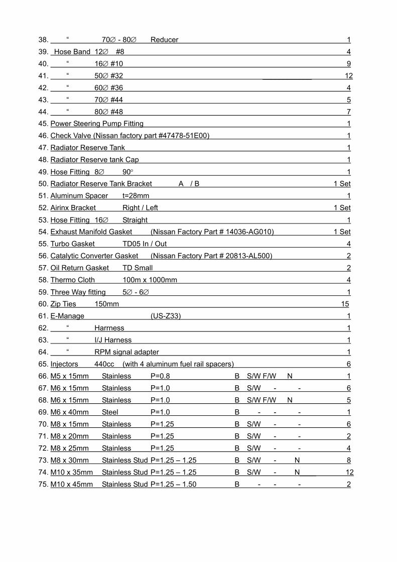
38. “ 70∅ - 80∅ Reducer 1 39. Hose Band 12∅ #8 4 40. “ 16∅ #10 9 41. “ 50∅ #32 ____________ 12 42. “ 60∅ #36 4 43. “ 70∅ #44 5 44. “ 80∅ #48 7 45. Power Steering Pump Fitting 1 46. Check Valve (Nissan factory part #47478-51E00) 1 47. Radiator Reserve Tank 1 48. Radiator Reserve tank Cap 1
49. Hose Fitting 8∅ 90° 1 50. Radiator Reserve Tank Bracket A / B 1 Set 51. Aluminum Spacer t=28mm 1 52. Airinx Bracket Right / Left 1 Set
53. Hose Fitting 16∅ Straight 1 54. Exhaust Manifold Gasket (Nissan Factory Part # 14036-AG010) 1 Set 55. Turbo Gasket TD05 In / Out 4 56. Catalytic Converter Gasket (Nissan Factory Part # 20813-AL500) 2 57. Oil Return Gasket TD Small 2 58. Thermo Cloth 100m x 1000mm 4
59. Three Way fitting 5∅ - 6∅ 1 60. Zip Ties 150mm 15 61. E-Manage (US-Z33) 1 62. “ Harrness 1 63. “ I/J Harness 1 64. “ RPM signal adapter 1 65. Injectors 440cc (with 4 aluminum fuel rail spacers) 6 66. M5 x 15mm Stainless P=0.8 B S/W F/W N 1 67. M6 x 15mm Stainless P=1.0 B S/W - - 6 68. M6 x 15mm Stainless P=1.0 B S/W F/W N 5 69. M6 x 40mm Steel P=1.0 B - - - 1 70. M8 x 15mm Stainless P=1.25 B S/W - - 6 71. M8 x 20mm Stainless P=1.25 B S/W - - 2 72. M8 x 25mm Stainless P=1.25 B S/W - - 4 73. M8 x 30mm Stainless Stud P=1.25 – 1.25 B S/W - N 8 74. M10 x 35mm Stainless Stud P=1.25 – 1.25 B S/W - N____ 12 75. M10 x 45mm Stainless Stud P=1.25 – 1.50 B - - - 2

1. Parts List
1 2 3 4
5 6 7 8
9 10 11 12
13 14 15 16
17 18 19 20

1. Parts List
21 22 23 24
25 26 27 28
29 30 - 33 34 - 38 39 - 40
45 46 47 48
49 50 51 52

1. Parts List
53 54 55 56
57 58 59 60
61 62 63 64
65 66 - 75

2. Factory Parts Removal
When removing the stock parts, make sure you read over the
factory repair manual for proper procedures.
2-1 Disconnect the negative terminal of the battery. 2-2 Drain the engine oil, coolant and power steering fluid. 2-3 Disconnect the air flow meter. 2-4 Remove the Air cleaner assembly with airflow meter, intake tube, and breather
hose. 2-5 Remove the Top Radiator Hose and the Water Pipe (Located above the Right
Exhaust manifold). 2-5 Disconnect the primary and secondary O2 sensor and remove the exhaust
manifold and catalytic converter. 2-6 Remove the exhaust manifold. 2-7 Remove oil pan (Please refer to the factory service manual for detail instructions f or removing the oil pan.) 2-8 Remove the upper intake manifold collector, fuel rail assembly with injectors and
regulator.

3. Turbo Kit Installation Thermo Cloth Installation • Remove the bracket securing the fuel line right below the right side shock tower and
disconnect the fuel line. Flip the connector so that the line points up and reconnect the line. Double wrap the fuel and evap Line using safety Wire. Leave the top bracket off and secure the bottom back on as shown.
(Parts used #58)
(This picture shows the turbo already installed)
Important! • Make sure that the fuel line is secured away from the turbine housing when the
turbo is installed. Some bending of the lines is necessary to achieve good clearance.
• Make sure the lines are properly wrapped twice. • Make sure to use safety wire to wrap the thermo cloth. Zip ties will melt from the
heat and eventually will come off. • Make sure that the fuel line connector is properly clicked in all the way. • GReddy Performance Products, Inc. will not be responsible for any damage
caused due to improper installation.

Caution! • Make sure to check and double check this step. This is the most important
step in this install. • Without proper clearance and thermo wrapping the fuel lines, the fuel line
connector can melt from heat and may catch on fire. • Wrap the Starter and the Main Engine
harness right above the transmission bell housing.
Important!
Make sure that the main engine harness is properly wrapped and secured away from the manifold and the wastegate when they are installed.
Caution!
Without proper clearance and thermo wrapping the harness, it melt and cause a short in the electrical system or may catch on fire.
Power Steering Line Installation 1. Remove the hose fitting off the power
steering pump and install the provided fitting.
(Parts Used #40, 45) 2. Cut the provided 15∅ hose to 200mm (8in)
and install it between the pump and the tank.
(Parts Used #33)
Oil Pan Installation Install the Oil pan with a silicone sealant.
(Part Used #29)

Oil Pressure Line Installation Install the oil pressure line to engine block using provided fittings.
(Part Used #20, 21, 22, 23, 24) 600mm line is for the right side and 800mm line is for the left side.
Exhaust Manifold Installation 1. Remove all factory exhaust manifold stud bolt off from the cylinder head. Install the
provided M10 x 35mm stud bolts on to the cylinder head as shown. (Part Used #74)
Right Side (Passenger’s Side)
Front of
the engine
Install Stud Bolt
Left Side (Driver’s Side)
Install Stud Bolt
Fro
nt o
f th
e en
gine
2. Install the Exhaust Manifold using provided gasket and hardware. (Part Used #3, 4, 54, 74)
Left Side (Driver’s Side) Right Side (Passenger’s Side)
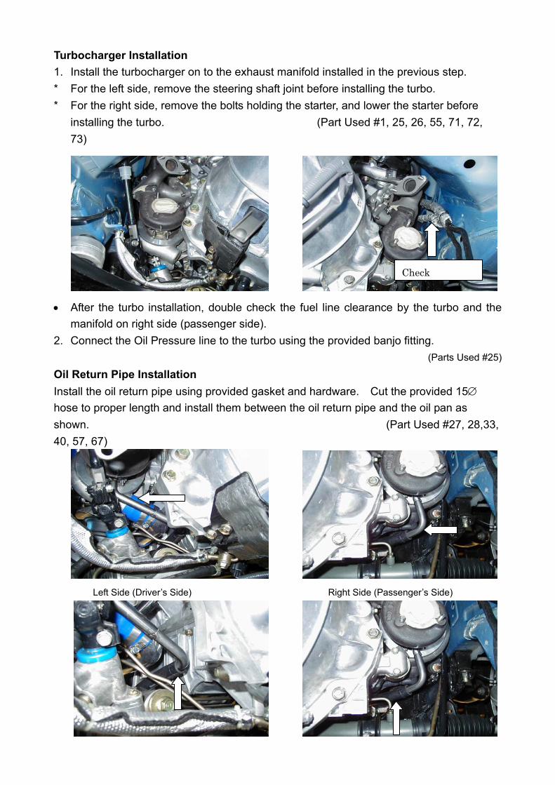
Turbocharger Installation 1. Install the turbocharger on to the exhaust manifold installed in the previous step. * For the left side, remove the steering shaft joint before installing the turbo. * For the right side, remove the bolts holding the starter, and lower the starter before
installing the turbo. (Part Used #1, 25, 26, 55, 71, 72, 73)
Check
• After the turbo installation, double check the fuel line clearance by the turbo and the manifold on right side (passenger side).
2. Connect the Oil Pressure line to the turbo using the provided banjo fitting. (Parts Used #25)
Oil Return Pipe Installation Install the oil return pipe using provided gasket and hardware. Cut the provided 15∅ hose to proper length and install them between the oil return pipe and the oil pan as shown. (Part Used #27, 28,33, 40, 57, 67)
Left Side (Driver’s Side) Right Side (Passenger’s Side)

Wastegate Installation Install the provided banjo fitting on to the bottom port of the wastegate. (Top Port is used for boost controller) Install the wastegate using the provided gasket and hardware as shown. (Part Used #2, 73)
Left Side (Driver’s Side) Right Side (Passenger’s Side) • Double check the clearance between the wastegate and the main engine harness on
the right side (passenger side). Make sure that there is enough clearance to avoid the harness from getting to hot and melting.
Down Pipe Adapter Installation Install the down pipe adapter using the provided gasket and hardware as shown.
(Part Used #5, 6, 55, 70, 72)
Exhaust System Installation Install the catalytic converter and the exhaust system using the provided gasket and hardware as shown.
(Part Used #56, 75)
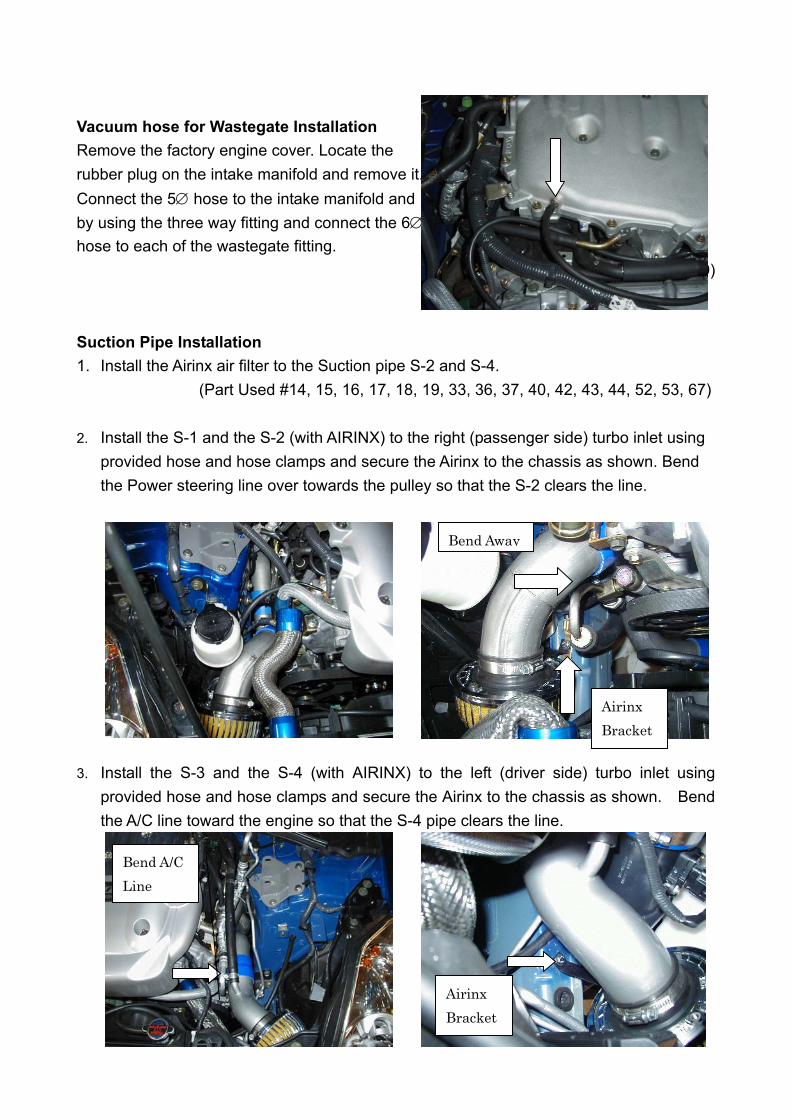
Vacuum hose for Wastegate Installation Remove the factory engine cover. Locate the rubber plug on the intake manifold and remove it. Connect the 5∅ hose to the intake manifold and by using the three way fitting and connect the 6∅ hose to each of the wastegate fitting.
(Part Used #30, 31, 59)
Suction Pipe Installation 1. Install the Airinx air filter to the Suction pipe S-2 and S-4.
(Part Used #14, 15, 16, 17, 18, 19, 33, 36, 37, 40, 42, 43, 44, 52, 53, 67)
2. Install the S-1 and the S-2 (with AIRINX) to the right (passenger side) turbo inlet using provided hose and hose clamps and secure the Airinx to the chassis as shown. Bend the Power steering line over towards the pulley so that the S-2 clears the line.
Bend Away
Airinx Bracket
3. Install the S-3 and the S-4 (with AIRINX) to the left (driver side) turbo inlet using provided hose and hose clamps and secure the Airinx to the chassis as shown. Bend the A/C line toward the engine so that the S-4 pipe clears the line.
Bend A/C Line
Airinx Bracket
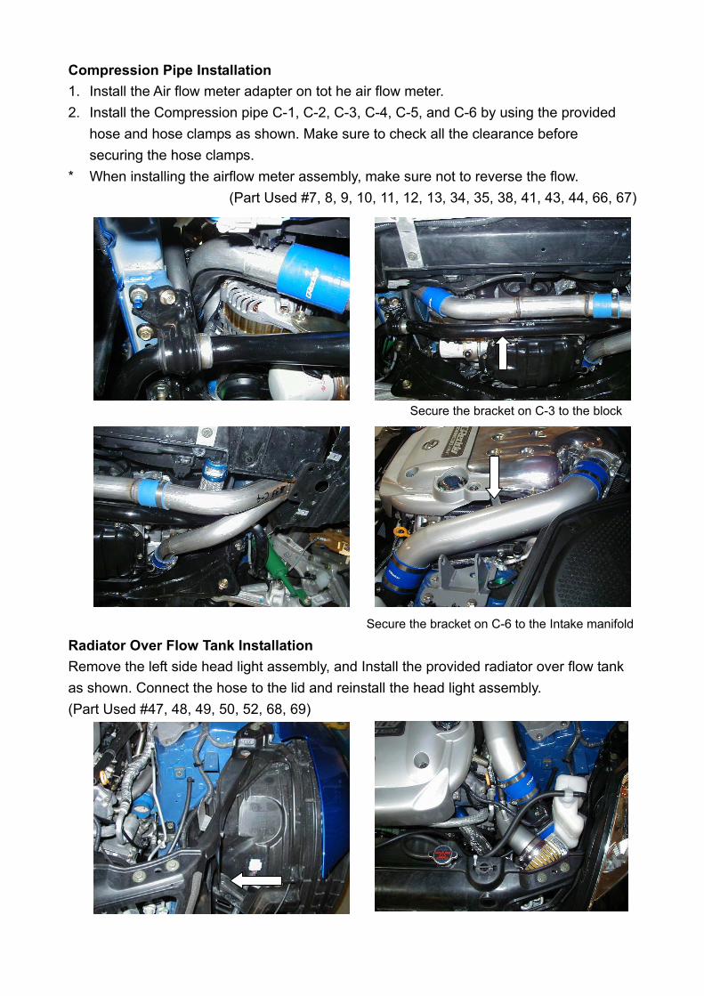
Compression Pipe Installation 1. Install the Air flow meter adapter on tot he air flow meter. 2. Install the Compression pipe C-1, C-2, C-3, C-4, C-5, and C-6 by using the provided
hose and hose clamps as shown. Make sure to check all the clearance before securing the hose clamps.
* When installing the airflow meter assembly, make sure not to reverse the flow. (Part Used #7, 8, 9, 10, 11, 12, 13, 34, 35, 38, 41, 43, 44, 66, 67)
Secure the bracket on C-3 to the block
Secure the bracket on C-6 to the Intake manifold
Radiator Over Flow Tank Installation Remove the left side head light assembly, and Install the provided radiator over flow tank as shown. Connect the hose to the lid and reinstall the head light assembly. (Part Used #47, 48, 49, 50, 52, 68, 69)
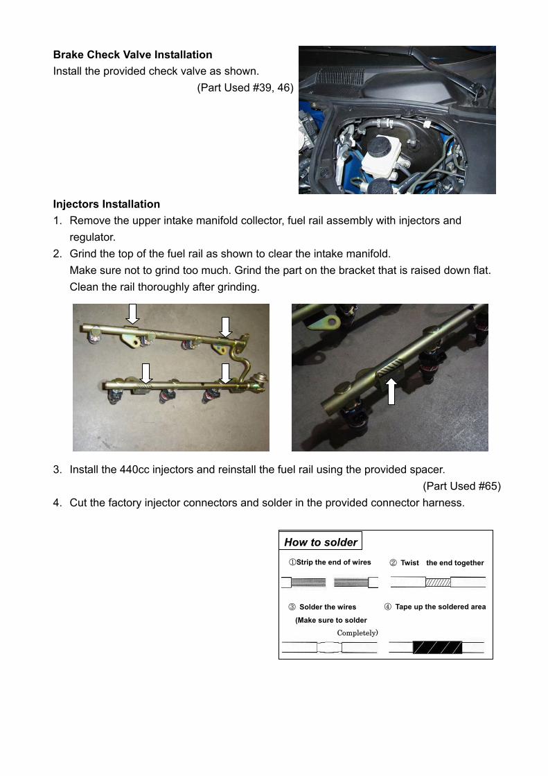
Brake Check Valve Installation Install the provided check valve as shown.
(Part Used #39, 46)
Injectors Installation 1. Remove the upper intake manifold collector, fuel rail assembly with injectors and
regulator. 2. Grind the top of the fuel rail as shown to clear the intake manifold.
Make sure not to grind too much. Grind the part on the bracket that is raised down flat. Clean the rail thoroughly after grinding.
3. Install the 440cc injectors and reinstall the fuel rail using the provided spacer.
(Part Used #65) 4. Cut the factory injector connectors and solder in the provided connector harness.
Completely) (Make sure to solder
④ Tape up the soldered area ③ Solder the wires
② Twist the end together ①Strip the end of wires
How to solder

E-manage Installation Install the e-manage and the rpm adapter as shown in the diagram. Make sure to solder all connections except for the ones that are supplied with the male and female connectors.
(Part Used #61, 62, 63, 64) Important! • Make sure you fully understand the diagram before attempting this installation. • Improper wiring can damage the ECM and the vehicle's electrical system. • GReddy Performance Product, Inc. will not be responsible for any damage caused by
improper installation. • Please do not use crimp connectors or t-tap connectors. These can cause poor
connection and prevent e-manage to operate properly.
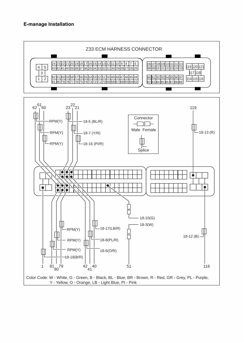
E-manage Installation
24 23 22 21 20 19 18 17 16 15 14 13 12 11 10 9 8 7 6 43 42 41 40 39 38 37 36 35 34 33 32 31 30 29 28 27 26 25
62 61 60 59 58 57 56 55 54 53 52 51 50 49 48 47 46 45 4481 80 79 78 77 76 75 74 73 72 71 70 69 68 67 66 65 64 63
106 107 108 109 110 111 112 11398 99 100 101 102 103 104 105
90 91 92 93 94 95 96 9782 83 84 85 86 87 88 89
4 5
3
1 2
119 120 121
117 118
114 115 116
Z33 ECM HARNESS CONNECTOR
Connector
Splice
Male Female
Color Code: W - White, G - Green, B - Black, BL - Blue, BR - Brown, R - Red, GR - Grey, PL - Purple, � Y - Yellow, O - Orange, LB - Light Blue, PI - Pink
62 6061
23 2122
81 7980
42 4041
RPM(Y)
RPM(Y)
RPM(Y)
RPM(Y)
RPM(Y)
RPM(Y)
18-18(B/R)
1
18-5 (BL/R)
18-7 (Y/R)
18-16 (PI/R)
18-17(LB/R)
18-8(PL/R)
18-6(O/R)
18-10(G)
18-3(W)
18-13 (R)
119
18-12 (B)
51 116

E-manage Installation
e-manage Factory ECU Pin # Wire Color Description ECU Pin # Color Code 3 White MAP IN 51
(harness Side)
Orange Airflow Meter
5 Blue/ Red
INJ 1 23 Red/ Black
INJ 1
6 Orange/ Red
INJ 2 42 Black/ Red
INJ 2
7 Yellow/ Red
INJ 3 22 Red/ Yellow
INJ 3
8 Purple/ Red
INJ 4 41 White/ Red
INJ 4
10 Green MAP OUT
51 (ECU side) Orange Airflow Meter
11 brown RPM RPM Adapter
Brown
12 Black GND 116 Black/ Red
ECM ground
13 Red +B 119 Green/ Yellow
ECM Power
16 Pink/Red INJ 5 21 Sky blue INJ 5 17 Light Blue/
Red INJ 6 40 Light
green INJ 6
18 Black/ Red
INJ GND 1 Black ECM ground
* Looking at harness side.
I/J Harness (18Pin)
Sensor Adapter Connect to Wire Color Description Pin # Color Code
Yellow RPM IN 60 ECU PU/ W IG#5 Yellow RPM IN 61 ECU L/R IG#3 Yellow RPM IN 62 ECU Y/R IG#1 Yellow RPM IN 79 ECU GY/R IG#6
Yellow RPM IN 80 ECU GY IG#4
Yellow RPM IN 81 ECU G/b IG#2
Brown RPM OUT 18 - 11
e-manage Brown RPM
Black GND 116 ECU
Black/RedECM Ground

Starting the Engine 1. Refill the engine oil to factory spec. 2. Check all the hoses and wires connection, then reconnect the negative side of the
battery. 3. Turn the ignition to “ON” position 2-3 times to get fuel pressure. Then, check the
injectors and the fuel rail for any fuel leaks. * Repair any fuel leaks before starting the engine. Starting the engine with a
fuel leak can cause fire in the engine compartment and can be very dangerous.
4. Remove the ECM fuse and crank the engine to get oil pressure to the turbo. (Until the
oil light on the dash turns off) Check for any oil leaks, then reinstall the fuse and start the engine.
5. While idling, check for any oil, coolant, or air leeks. 6. After inspection, reinstall the under cover and other stock parts that was removed. 7. On the initial run, be sure to have a boost gauge to check the turbo-actuator setting.
This turbo kit is preset to boost between 0.4kg/cm2 to 0.45kg/cm2 . It is very important that you monitor the boost pressure, and make sure not to over
boost. Over boosting can cause engine damage.
This completes the Turbo Kit installation.
Important! • It is very important that you monitor the boost pressure, and make sure not to
over boost. Over boosting can cause engine damage.
• GReddy Performance Products, Inc. is not responsible for any engine damage caused by over boosting (increased boost), modification to the kit, and/or misuse of the product. NO WARRANTY is offered.
• Due to lack of control over proper installation and use of this product, NO WARRANTY is offered for this kit.

e-manage Information
Important! • The e-manage included in this kit is preprogrammed for the this turbo kit. • Do not attempt to adjust any of the setting in the e-manage. • Any adjustments made can cause damage to the e-manage, engine and the
factory ECU.
Important!
As of 11/25/03 this kit is not a street legal kit. Please ignore the label on the e-manage.
ACTIVE L.E.D. (2) When the ignition is turned on, it will illuminate and flash GREEN.
(3) When it reaches to the A.A.V. setting RPM range, it will illuminate and flash ORANGE.
(4) When an error is detected it will flash RED.
INTERACTION L.E.D. 1. This will illuminate when there is a connection with PC.
Checking Error Codes When the unit is powered up and if there are any errors, the ACTIVE L.E.D will turn
“RED” from “GREEN”, and begin to flash. If this happens shut the engine off and turn the ignition switch to “ON”
position to go to Self Troubleshooting Mode. While in the Self Troubleshooting Mode, the L.E.D. will show the error code. Turn off the ignition. Check the error code in the chart below and fix the problem. The error code will show until the error is corrected.