Embed Size (px)
Citation preview

Graphical Model
Manipulation Guide

DisclaimerInformation of a technical nature, and particulars of the product and its use, is given by AVEVASolutions Ltd and its subsidiaries without warranty. AVEVA Solutions Ltd and its subsidiaries disclaimany and all warranties and conditions, expressed or implied, to the fullest extent permitted by law.
Neither the author nor AVEVA Solutions Ltd, or any of its subsidiaries, shall be liable to any person orentity for any actions, claims, loss or damage arising from the use or possession of any information,particulars, or errors in this publication, or any incorrect use of the product, whatsoever.
CopyrightCopyright and all other intellectual property rights in this manual and the associated software, and everypart of it (including source code, object code, any data contained in it, the manual and any otherdocumentation supplied with it) belongs to AVEVA Solutions Ltd or its subsidiaries.
All other rights are reserved to AVEVA Solutions Ltd and its subsidiaries. The information contained inthis document is commercially sensitive, and shall not be copied, reproduced, stored in a retrievalsystem, or transmitted without the prior written permission of AVEVA Solutions Ltd. Where suchpermission is granted, it expressly requires that this Disclaimer and Copyright notice is prominentlydisplayed at the beginning of every copy that is made.
The manual and associated documentation may not be adapted, reproduced, or copied, in any materialor electronic form, without the prior written permission of AVEVA Solutions Ltd. The user may also notreverse engineer, decompile, copy, or adapt the associated software. Neither the whole, nor part of theproduct described in this publication may be incorporated into any third-party software, product,machine, or system without the prior written permission of AVEVA Solutions Ltd, save as permitted bylaw. Any such unauthorised action is strictly prohibited, and may give rise to civil liabilities and criminalprosecution.
The AVEVA products described in this guide are to be installed and operated strictly in accordance withthe terms and conditions of the respective licence agreements, and in accordance with the relevantUser Documentation. Unauthorised or unlicensed use of the product is strictly prohibited.
First published September 2007
© AVEVA Solutions Ltd, and its subsidiaries 2007
AVEVA Solutions Ltd, High Cross, Madingley Road, Cambridge, CB3 0HB, United Kingdom
TrademarksAVEVA and Tribon are registered trademarks of AVEVA Solutions Ltd or its subsidiaries. Unauthoriseduse of the AVEVA or Tribon trademarks is strictly forbidden.
AVEVA product names are trademarks or registered trademarks of AVEVA Solutions Ltd or itssubsidiaries, registered in the UK, Europe and other countries (worldwide).
The copyright, trade mark rights, or other intellectual property rights in any other product, its name orlogo belongs to its respective owner.
AVEVA Solutions Ltd

Graphical Model Manipulation Guide
Contents Page
Graphical Model Manipulation Guide
Graphical ModelIntroducing the Design Model Editor . . . . . . . . . . . . . . . . . . . . . . . . 1:1Scope of this Guide . . . . . . . . . . . . . . . . . . . . . . . . . . . . . . . . . . . . . . . . . . . . . . . . 1:1Glossary . . . . . . . . . . . . . . . . . . . . . . . . . . . . . . . . . . . . . . . . . . . . . . . . . . . . . . . . 1:1
Selection . . . . . . . . . . . . . . . . . . . . . . . . . . . . . . . . . . . . . . . . . . . . . . . 2:1Introducing Element Selection . . . . . . . . . . . . . . . . . . . . . . . . . . . . . . . . . . . . . . . 2:1Selecting Piping Components . . . . . . . . . . . . . . . . . . . . . . . . . . . . . . . . . . . . . . . 2:1Menus on Selection Sets. . . . . . . . . . . . . . . . . . . . . . . . . . . . . . . . . . . . . . . . . . . . 2:5Equipment Items . . . . . . . . . . . . . . . . . . . . . . . . . . . . . . . . . . . . . . . . . . . . . . . . . . . . . . . . . 2:5Piping Components . . . . . . . . . . . . . . . . . . . . . . . . . . . . . . . . . . . . . . . . . . . . . . . . . . . . . . . 2:6
Component Deselection . . . . . . . . . . . . . . . . . . . . . . . . . . . . . . . . . . . . . . . . . . . . 2:6
Introducing the Model Editor 3D View. . . . . . . . . . . . . . . . . . . . . . . . 3:13D View Windows. . . . . . . . . . . . . . . . . . . . . . . . . . . . . . . . . . . . . . . . . . . . . . . . . . 3:1Manipulating the Design Model View . . . . . . . . . . . . . . . . . . . . . . . . . . . . . . . . . . 3:13D View Menu . . . . . . . . . . . . . . . . . . . . . . . . . . . . . . . . . . . . . . . . . . . . . . . . . . . . . . . . . . . 3:2Mouse Wheel Zoom . . . . . . . . . . . . . . . . . . . . . . . . . . . . . . . . . . . . . . . . . . . . . . . . . . . . . . . 3:7Design Item Entries . . . . . . . . . . . . . . . . . . . . . . . . . . . . . . . . . . . . . . . . . . . . . . . . . . . . . . . 3:8View Manipulation Toolbar Buttons . . . . . . . . . . . . . . . . . . . . . . . . . . . . . . . . . . . . . . . . . . . 3:9Clipping and Capping. . . . . . . . . . . . . . . . . . . . . . . . . . . . . . . . . . . . . . . . . . . . . . . . . . . . . . 3:9
Model Editor Operations. . . . . . . . . . . . . . . . . . . . . . . . . . . . . . . . . . . 4:1Model Editor Mode . . . . . . . . . . . . . . . . . . . . . . . . . . . . . . . . . . . . . . . . . . . . . . . . . 4:1Element Selection in the Model Editor . . . . . . . . . . . . . . . . . . . . . . . . . . . . . . . . . . . . . . . . . 4:2
12.0i© 2007 AVEVA Solutions Ltd

Graphical Model Manipulation Guide
Locator Handle . . . . . . . . . . . . . . . . . . . . . . . . . . . . . . . . . . . . . . . . . . . . . . . . . . . . . . . . . . . 4:3Movement . . . . . . . . . . . . . . . . . . . . . . . . . . . . . . . . . . . . . . . . . . . . . . . . . . . . . . . . . . . . . . 4:4Rotation . . . . . . . . . . . . . . . . . . . . . . . . . . . . . . . . . . . . . . . . . . . . . . . . . . . . . . . . . . . . . . 4:5Alignment . . . . . . . . . . . . . . . . . . . . . . . . . . . . . . . . . . . . . . . . . . . . . . . . . . . . . . . . . . . . . . 4:6Locator Handle as a Frame of Reference . . . . . . . . . . . . . . . . . . . . . . . . . . . . . . . . . . . . . . 4:7Feedback . . . . . . . . . . . . . . . . . . . . . . . . . . . . . . . . . . . . . . . . . . . . . . . . . . . . . . . . . . . . . . 4:7Unconstrained Positioning . . . . . . . . . . . . . . . . . . . . . . . . . . . . . . . . . . . . . . . . . . . . . . . . . . 4:7Undo and Redo . . . . . . . . . . . . . . . . . . . . . . . . . . . . . . . . . . . . . . . . . . . . . . . . . . . . . . . . . . 4:7Performance. . . . . . . . . . . . . . . . . . . . . . . . . . . . . . . . . . . . . . . . . . . . . . . . . . . . . . . . . . . . . 4:7
Element Selection in the Model Editor. . . . . . . . . . . . . . . . . . . . . . . . . . . . . . . . . 4:8Selection Feedback . . . . . . . . . . . . . . . . . . . . . . . . . . . . . . . . . . . . . . . . . . . . . . . . . . . . . . . 4:8Selecting Items Using the Mouse Pointer . . . . . . . . . . . . . . . . . . . . . . . . . . . . . . . . . . . . . . 4:8Fence Selection . . . . . . . . . . . . . . . . . . . . . . . . . . . . . . . . . . . . . . . . . . . . . . . . . . . . . . . . . . 4:9Item-Specific Selection Operations . . . . . . . . . . . . . . . . . . . . . . . . . . . . . . . . . . . . . . . . . . 4:11Clearing the Graphical Selection . . . . . . . . . . . . . . . . . . . . . . . . . . . . . . . . . . . . . . . . . . . . 4:13Reinstating the Previous Graphical Selection . . . . . . . . . . . . . . . . . . . . . . . . . . . . . . . . . . 4:13Selection Menu. . . . . . . . . . . . . . . . . . . . . . . . . . . . . . . . . . . . . . . . . . . . . . . . . . . . . . . . . . 4:13
Positioning and Orientation using the Locator Handle . . . . . . . . . . . . . . . . . . 4:15Overview . . . . . . . . . . . . . . . . . . . . . . . . . . . . . . . . . . . . . . . . . . . . . . . . . . . . . . . . . . . . . 4:15Linear Movement Handle . . . . . . . . . . . . . . . . . . . . . . . . . . . . . . . . . . . . . . . . . . . . . . . . . . 4:16Planar Movement Handles . . . . . . . . . . . . . . . . . . . . . . . . . . . . . . . . . . . . . . . . . . . . . . . . . 4:22Rotation Handle . . . . . . . . . . . . . . . . . . . . . . . . . . . . . . . . . . . . . . . . . . . . . . . . . . . . . . . . . 4:25Feature Highlighting . . . . . . . . . . . . . . . . . . . . . . . . . . . . . . . . . . . . . . . . . . . . . . . . . . . . . . 4:29Moving the Locator Handle Independently of the Graphical Selection. . . . . . . . . . . . . . . . 4:31
Positioning and Orientation Using the Edit Menu. . . . . . . . . . . . . . . . . . . . . . . 4:31Move Selection and Move Handle . . . . . . . . . . . . . . . . . . . . . . . . . . . . . . . . . . . . . . . . . . . 4:31Rotate Selection and Rotate Handle . . . . . . . . . . . . . . . . . . . . . . . . . . . . . . . . . . . . . . . . . 4:33
Clipping . . . . . . . . . . . . . . . . . . . . . . . . . . . . . . . . . . . . . . . . . . . . . . . . . . . . . . . 4:34Clipping Submenu . . . . . . . . . . . . . . . . . . . . . . . . . . . . . . . . . . . . . . . . . . . . . . . . . . . . . . . 4:34Six-Plane Clipping . . . . . . . . . . . . . . . . . . . . . . . . . . . . . . . . . . . . . . . . . . . . . . . . . . . . . . . 4:35
Undo and Redo. . . . . . . . . . . . . . . . . . . . . . . . . . . . . . . . . . . . . . . . . . . . . . . . . . . 4:40Delete Selection . . . . . . . . . . . . . . . . . . . . . . . . . . . . . . . . . . . . . . . . . . . . . . . . . . 4:41Selectable Items . . . . . . . . . . . . . . . . . . . . . . . . . . . . . . . . . . . . . . . . . . . . . . . . . . 4:41
Graphical Equipment Modification . . . . . . . . . . . . . . . . . . . . . . . . . . 5:1Introducing Graphical Equipment Modification . . . . . . . . . . . . . . . . . . . . . . . . . 5:1Equipment Modification Characteristics and Facilities . . . . . . . . . . . . . . . . . . . 5:2Display Characteristics. . . . . . . . . . . . . . . . . . . . . . . . . . . . . . . . . . . . . . . . . . . . . . . . . . . . . 5:2
12.0ii© 2007 AVEVA Solutions Ltd

Graphical Model Manipulation Guide
Modification Facilities . . . . . . . . . . . . . . . . . . . . . . . . . . . . . . . . . . . . . . . . . . . . . . . . . . . . . . 5:3
Graphical Component Modification. . . . . . . . . . . . . . . . . . . . . . . . . . 6:1Introducing Graphical Component Modification. . . . . . . . . . . . . . . . . . . . . . . . . 6:1Selection Set for GCM . . . . . . . . . . . . . . . . . . . . . . . . . . . . . . . . . . . . . . . . . . . . . . 6:2Component Modification Handle . . . . . . . . . . . . . . . . . . . . . . . . . . . . . . . . . . . . . . . . . . . . . 6:3
Operations in GCM. . . . . . . . . . . . . . . . . . . . . . . . . . . . . . . . . . . . . . . . . . . . . . . . . 6:4Movement Handle . . . . . . . . . . . . . . . . . . . . . . . . . . . . . . . . . . . . . . . . . . . . . . . . . 6:4Dragging . . . . . . . . . . . . . . . . . . . . . . . . . . . . . . . . . . . . . . . . . . . . . . . . . . . . . . . . . . . . . . 6:5
Feature Highlighting. . . . . . . . . . . . . . . . . . . . . . . . . . . . . . . . . . . . . . . . . . . . . . 6:5Nudging the Handle . . . . . . . . . . . . . . . . . . . . . . . . . . . . . . . . . . . . . . . . . . . . . . . . . . . . . . . 6:6
Rotation Handle . . . . . . . . . . . . . . . . . . . . . . . . . . . . . . . . . . . . . . . . . . . . . . . . . . . 6:7Dragging . . . . . . . . . . . . . . . . . . . . . . . . . . . . . . . . . . . . . . . . . . . . . . . . . . . . . . . . . . . . . . 6:7Feature Highlighting . . . . . . . . . . . . . . . . . . . . . . . . . . . . . . . . . . . . . . . . . . . . . . . . . . . . . . . 6:8Nudging the Handle . . . . . . . . . . . . . . . . . . . . . . . . . . . . . . . . . . . . . . . . . . . . . . . . . . . . . . . 6:8Repositioning the Handle . . . . . . . . . . . . . . . . . . . . . . . . . . . . . . . . . . . . . . . . . . . . . . . . . . . 6:8
Movement and Rotation Characteristics . . . . . . . . . . . . . . . . . . . . . . . . . . . . . . . 6:9Movement Handle . . . . . . . . . . . . . . . . . . . . . . . . . . . . . . . . . . . . . . . . . . . . . . . . . . . . . . . . 6:9Rotation Handle . . . . . . . . . . . . . . . . . . . . . . . . . . . . . . . . . . . . . . . . . . . . . . . . . . . . . . . . . 6:14
Feedback . . . . . . . . . . . . . . . . . . . . . . . . . . . . . . . . . . . . . . . . . . . . . . . . . . . . . . . 6:15Movement Handle . . . . . . . . . . . . . . . . . . . . . . . . . . . . . . . . . . . . . . . . . . . . . . . . . . . . . . . 6:15Rotation Handle . . . . . . . . . . . . . . . . . . . . . . . . . . . . . . . . . . . . . . . . . . . . . . . . . . . . . . . . . 6:17
Popup Menus on the Component Modification Handle . . . . . . . . . . . . . . . . . . 6:17Movement Handle . . . . . . . . . . . . . . . . . . . . . . . . . . . . . . . . . . . . . . . . . . . . . . . . . . . . . . . 6:17Rotation Handle . . . . . . . . . . . . . . . . . . . . . . . . . . . . . . . . . . . . . . . . . . . . . . . . . . . . . . . . . 6:18
Hotkeys . . . . . . . . . . . . . . . . . . . . . . . . . . . . . . . . . . . . . . . . . . . . . . . . . . . . . . . 6:20
12.0iii© 2007 AVEVA Solutions Ltd

Graphical Model Manipulation Guide
12.0iv© 2007 AVEVA Solutions Ltd

Graphical Model Manipulation GuideIntroducing the Design Model Editor
1 Introducing the Design Model Editor
The Design Model Editor enables you to reposition selected objects in a model using themouse pointer. Model manipulation using the Model Editor takes place within the ModelEditor 3D View, which incorporates features specific to that View type.
1.1 Scope of this GuideThis guide introduces the facilities in both the Model Editor 3D View and the Model Editoritself. This manual is set out as follows:
• Selection introduces element Selection, and the meanings of the different Selectiongraphics.
• Introducing the Model Editor 3D View introduces the Model Editor mode of operationwithin a 3D View Window.
• Model Editor Operations introduces the Model Editor itself, describing the selection,positioning and orientation facilities available within Model Editor mode.
• Graphical Equipment Modification introduces the facilities that have options to speedthe modification of Equipment.
• Graphical Component Modification introduces the modification facility which allows youto interactively move piping Components along the legs of a pipe route and rotate themabout the centreline of the pipe tube.
1.2 Glossary
Feature Point, P-point, line or P-line on the 3D model that can beused for alignment.
Graphical Selection One or more elements selected for subsequentmanipulation using the Locator Handle.
Selection Set When in Navigate mode, the elements selected by apointer click. For an Equipment, all the constituentprimitives will be selected, for a piping Component, allconnected Components will be selected.
Linear Movement Handle
A handle situated on the Locator Handle, which whenselected for a drag operation, constrains movement of theselection to be along the direction of the selected majoraxis.
12.0 1:1© 2007 AVEVA Solutions Ltd

Graphical Model Manipulation GuideIntroducing the Design Model Editor
Locator Handle A collection of handles which together provide amechanism for positioning and orientation of selectedelements.
Movement Increment
The incremental step in current distance units that aselection will move in the direction of a major axis of theLocator Handle when a planar movement handle or alinear movement handle is dragged.
Movement Axis The axis identified by the Linear Movement Handle.During a drag operation, the current selection will beconstrained to move in the direction of the movement axisonly, while following the movement of the pointer.
Movement Plane The plane identified by the Planar Movement Handle.During a drag operation, the current selection will beconstrained to move in the Movement Plane only, whilefollowing the movement of the pointer.
Planar Movement Handle
A handle situated on the Locator Handle, which whenselected for a drag operation constrains movement of theselection to be in the plane indicated by the PlanarMovement Handle. That is, the XY, XZ or YZ plane of theLocator Handle.
Rotation Increment Incremental step in degrees that a selection will rotatewhen a Locator rotation handle is dragged.
Reference Point Position used as a datum point for subsequent movementof the Graphical Selection.
Plant Item A Design database element that represents anengineering item that can be individually selected andmanipulated to modify plant layout. For example,Equipment, Steel Section, Piping Component.
12.0 1:2© 2007 AVEVA Solutions Ltd

Graphical Model Manipulation GuideSelection
2 Selection
2.1 Introducing Element SelectionSelecting an element (when not in Model Editor mode) highlights that element and all of itsconstituent primitives with a green line:
The highlight colour used is the same irrespective of whether you have read/write accessrights or read-only access rights.
Note: This is not the case in Model Editor mode.
2.2 Selecting Piping ComponentsWhen selecting a piping Component, all related items are also selected. For example, whenselecting a Valve, the related Flanges and Gaskets are selected as well:
12.0 2:1© 2007 AVEVA Solutions Ltd

Graphical Model Manipulation GuideSelection
Note: The selected elements (known as the Selection Set), only constitute the graphicalselection (as highlighted with a green line) - the selected current element is (in theabove case) still only the Valve element itself.
The above situation only applies where the arrive and leave directions of the selected pipingComponent are in line with each other. In the case of (for example), an Elbow, only theElbow itself and any connected zero-length Components (e.g. Welds) are selected. Seebelow:
Diagrammatically, the above situation is:
12.0 2:2© 2007 AVEVA Solutions Ltd

Graphical Model Manipulation GuideSelection
If a Component which has arrive and leave directions which are in line also hasComponents which are directly connected to it, then those Components are selected aswell. For example:
Connected Components are selected up to, but not including:• An element which changes direction, e.g. Elbow, Bend, etc.• A ‘directly connected-to element’, e.g. Tee, Cross, etc. where the CREF or CRFA is set• A bad alignment between Components, e.g. bad offset, alignment, etc.
Further examples of Component selection sets are shown below:
Example: Flanged Valve within a straight leg of a Branch.
12.0 2:3© 2007 AVEVA Solutions Ltd

Graphical Model Manipulation GuideSelection
Example: Flanged Valve with weld-neck Flanges connected to an Elbow:
Example: Connected assembly between a change in direction and connected Tee:
Example: Connected assembly between a change in direction and an unconnected Tee:
12.0 2:4© 2007 AVEVA Solutions Ltd

Graphical Model Manipulation GuideSelection
Example: Bad alignment, between Valve assembly and one of its flanges:
2.3 Menus on Selection Sets
2.3.1 Equipment Items
In the example shown above, De-Select All would de-select the entire pump; De-SelectCurrent would clear the graphical selection of the current element but leave the rest of theelements in the selection selected.
12.0 2:5© 2007 AVEVA Solutions Ltd

Graphical Model Manipulation GuideSelection
2.3.2 Piping Components
Note: The above menu is for selection using the right-hand mouse button - only theelement under the pointer is selected. Selection using the left-hand mouse buttonselects the element under the pointer and connected elements.
Select Connected selects all Components connected to the current Component. SelectLeg. selects Components in the same Pipe leg as the current Component.
All other options are as for Model Editing mode.
2.4 Component DeselectionCtrl-click on a selected item removes it from the current selection set.
Holding the key down while dragging out a selection rectangle removes the selecteditems from the current selection set.
Connected zero length or connected invisible components should never be left orphanedwhen either of their adjacent components are removed from the selection set.
Example: De-selection of a flanged break in line:
12.0 2:6© 2007 AVEVA Solutions Ltd

Graphical Model Manipulation GuideSelection
12.0 2:7© 2007 AVEVA Solutions Ltd

Graphical Model Manipulation GuideSelection
12.0 2:8© 2007 AVEVA Solutions Ltd

Graphical Model Manipulation GuideIntroducing the Model Editor 3D View
3 Introducing the Model Editor 3D View
3.1 3D View Windows3D Views within DESIGN may be used in one of three modes of operation:
• Navigate mode• Event Driven Graphics mode• Model Editor mode
3D View windows can be used to display all or part of the design model. No graphics aredisplayed in a 3D View window until model elements are added to the draw list and viewlimits are set.
In Navigate Mode (the default setting), view windows allow you to select an element simplyby clicking on it, which navigates to it in the database and makes it the current element. Inthis mode, the prompt bar across the top of the viewing area contains the prompt Navigate:.
In Event-Driven Graphics (EDG) mode, mouse pointer picks are used as part of an event-driven graphics routine. You are invited to perform a graphical pick on an element or agraphical feature in the displayed model. The prompt bar contains an instruction whichprompts you to perform a graphical selection. You are not able to enter Model Editor modewhilst in EDG mode (and vice versa).
In Model Editor mode, one or more elements can be selected, and those elements can bemoved or rotated dynamically by dragging with the mouse pointer. The prompt bar containsthe prompt Modify.
In this User Guide, a 3D View that can be switched into Model Editor mode is called a 3DModel Editor View. PDMS DESIGN normally starts with a 3D Model Editor View shown.New 3D Model Editor Views can be created by selecting Display>Graphical View from themenu bar, or by using the Create button on the 3D View Control form.
3.2 Manipulating the Design Model ViewView manipulation operations are accessed using:
• the View menu on the main menu bar• the 3D View , obtained by clicking on the 3D View background with the right mouse
button• buttons located next to the 3D view on a 3D View Window• function keys on the keyboard• menus on Design items• direct manipulation of the 3D view using the mouse.
12.0 3:1© 2007 AVEVA Solutions Ltd

Graphical Model Manipulation GuideIntroducing the Model Editor 3D View
This section describes the 3D View Window manipulation operations. Many of theseoperations can be accessed using more than one method. The View menu selections areintroduced, along with a note on other methods that may be used to invoke the sameoperations.
3.2.1 3D View Menu
View menu
3D View
12.0 3:2© 2007 AVEVA Solutions Ltd

Graphical Model Manipulation GuideIntroducing the Model Editor 3D View
• Middle Button Drag
The Middle Button Drag menu is used to set the action of subsequent middle mousebutton drag operations on a 3D View.
The model displayed in a 3D View can be zoomed, rotated or panned (according the menuoption selected) by pressing the middle mouse button or mouse wheel over the 3D Viewand moving the mouse.
Middle mouse button drag operations can also be set using function keys and buttons onthe 3D View: F2 for Zoom In/Out, F3 for Pan and F5 for Rotate.
Note: Walk mode is inactive unless the 3D view is displayed in perspective.
>Zoom Rectangle
Enables you to perform a zoom-in operation by dragging out a rectangle around the volumerequired to fill the 3D View.
>Zoom In/Out
Enables you, with the middle mouse button held down, to magnify or reduce the view bymoving the mouse up (away from you) to zoom in, or down (towards you) to zoom out.
The middle mouse button can be set in this mode by using the View main menu, the View ,the Zoom In/Out button on the 3D View Window and the F2 button on the keyboard.
>Rotate
In this mode, hold down the middle button and move the mouse up/down to rotate the viewvertically or left/right to rotate the view horizontally. The initial movement determines theaxis of rotation; to rotate about the other axis, release and press again the middle button.
The middle mouse button can be set in this mode by using the View main menu, the View,the Rotate button on the 3D View Window and the F5 button on the keyboard.
> Pan
Lets you move across the view in any direction. In this mode, hold down the middle buttonand move the mouse towards the part of the view that you want to see.
The middle mouse button can be set in this mode by using the View main menu, the View,the Pan button on the 3D View Window and the F3 button on the keyboard.
> Walk
Selects walkthrough mode, in which the eye point moves towards or away from the model(only works in perspective views). In this mode, hold down the middle button and move themouse up to walk towards the model or down to walk away from the model.
12.0 3:3© 2007 AVEVA Solutions Ltd

Graphical Model Manipulation GuideIntroducing the Model Editor 3D View
The middle mouse button can be set in this mode by using the View main menu, the View,the Walk button on the 3D View Window and the F6 button on the keyboard.
• Printing the 3D ViewThe content of the active 3D View Window can be output to a printer by clicking onView>Print Graphics…
This displays a standard Windows Print form, giving you the ability to select a printer, setthe number of copies to produce, and set properties of the print.
• Copying the 3D View to the Windows Paste Buffer
The content of the active 3D View Window can by copied to the Windows paste buffer byclicking on one of the View>Copy Image options. The options 640x480 up to 1600x1200refer to the resolution of the image copied to the paste buffer.
The copied image can be pasted into another Windows application that supports pictureobjects, such as a Word Processor or picture-editing package.
• Zoom To
Zoom To zooms and pans the 3D View to get the required part of the 3D model to fill theview window.
>Selection
The current element, or the graphical selection if one exists, fills the 3D View.
>Identify Element
This allows you to centre the view on an identified element in the graphics, and zooms theview such that the identified element fills the 3D View window.
Note: Identifying an element with a pointer pick in this way does not set the selectedelement to be the Current Element.
12.0 3:4© 2007 AVEVA Solutions Ltd

Graphical Model Manipulation GuideIntroducing the Model Editor 3D View
>Entire Draw List
This centres the view on the centre point of the entire draw list and zooms the view so thatall the elements in the display list fill the 3D View window.
• Walk ToWalk To zooms and pans the 3D View to get the required part of the 3D model to fill theview. Walk To differs from Zoom To in that it removes items between your eye position andthe target item that are not in the immediate vicinity of the target item. Items in theimmediate vicinity of the target will continue to be displayed, so it may be necessary toremove items still obscuring the target item by removing them from the Draw List.
• Save View and Restore View
Save View stores the current state of a 3D view so that the view direction and magnificationcan be restored when required. Up to four views can be saved at any one time.
Restore View allows you to select a saved view and change the active 3D view settings tothe saved values. Any of the views 1 to 4 that do not contain saved view details are greyedout.
Views can also be restored by using the Restore View buttons on the left side of the 3DView Window.
• Look, Plan and Isometric
Look
Allows you to select from a range of orthogonal views.
Plan
Allows you to view the model from above.
Isometric
Lets you select any of the four isometric views.
12.0 3:5© 2007 AVEVA Solutions Ltd

Graphical Model Manipulation GuideIntroducing the Model Editor 3D View
• Set Centre Of View
Set Centre Of View allows you to pan the 3D view such that the identified element orscreen position is centred in the 3D view.
>Selection
This centres the 3D view on the current element, or on the graphical selection if one exists.>Identified Element…
This allows you to centre the 3D view on an element picked with the mouse pointer.
Note: Identifying an element with a pick in this way does not set the picked element to bethe Current Element.
>Screen Pick
This allows you to identify a position (which could be in free space) in a 3D view to becomethe centre of view.
Clicking on the 3D view with the middle mouse button also performs this operation.
• Settings
The View>Settings menu appears on the main View menu only. It is not on the view .
>Eye, >Shaded, >Borders and >Perspective
These menu commands control the Eye, Shaded, Borders and Perspective modes.
>Black Background and >White Background
Sets the background colour of the currently active 3D View to black or white. Black isrecommended as the standard working colour for the view background. White can be thebest choice of background colour if a 3D view is to be printed, or its contents copied toanother application.
12.0 3:6© 2007 AVEVA Solutions Ltd

Graphical Model Manipulation GuideIntroducing the Model Editor 3D View
Other 3D view background colours can be set by using the 3D View Options form foundunder Settings>Graphics, 3D Views tab, and the 3D View Control form found underDisplay>View Control….
>High Quality
This feature can be used to toggle between ‘high’ and ‘standard’ quality images of theDesign model. A high quality image is slower to draw and manipulate than a standardquality one.
This option does not affect the Arc Tolerance property on the Representation tab of theGraphics Settings form (Settings>Graphics). This is an independent property that allowsyou to control the display quality of some of the more complex elements in PDMS.
>Show Tooltips
This feature toggles a ‘Tooltip’ function. If enabled, the name of the element under themouse pointer is displayed in the Tooltip.
>Animations
This feature toggles smooth pan and zoom operations in 3D View when the Zoom To andWalk To options are used. The zoom operation is animated to show the transition from theoriginal view definition to the final view definition. This feature only operates if the systemdetermines that the hardware is capable of performing a smooth pan and zoom with the sizeof model displayed in the 3D View.
3.2.2 Mouse Wheel Zoom
Rolling the mouse wheel forwards zooms in on the currently active 3D View. Rolling themouse wheel backwards zooms out on the currently active 3D View.
In both cases, holding down the or Ctrl key at the same time as rolling the mouse wheelcontrols the speed of the operation. Holding the Ctrl key down makes the mouse wheel
zoom in and out faster. Holding the key down makes the mouse wheel zoom in and outslower.
12.0 3:7© 2007 AVEVA Solutions Ltd

Graphical Model Manipulation GuideIntroducing the Model Editor 3D View
3.2.3 Design Item EntriesThis section describes view options on elements in the Model Editor. The element must beselected.
The following viewing options are available on a design item:
(Equipment Selected)
(Piping Component Selected)
Menu Option Description
Edit >Equipment Removes the Movement Handle (if present) from theEquipment item, allowing only Equipment editing functionsto be carried out. (The Movement Handle can be reinstated
if required by double-clicking on the icon on the maintoolbar.
Select>Connected (Piping Components only). Selects Components connectedto the selected Component.
Select>Leg (Piping Components only). Selects Components in thesame pipe leg as the selected Component.
Select>BRAN . . . (Piping Components only). Selects the owning Branch.
Select>PIPE . . . (Piping Components only). Selects the owning Pipe.
De-Select All Clears the current graphical selection.
De-Select Current Clears the graphical selection of the current element (butleaving the rest of the elements in the selection selected(for example, Components in a selected Branch)).
Hide Removes the graphical selection from the display, but doesnot remove it from the drawlist
Remove from Draw List Remove the graphical selection from the drawlist
Use 3D Handle (Piping Component selected) Switch back to 3D MovementHandle (see below for further details).
12.0 3:8© 2007 AVEVA Solutions Ltd

Graphical Model Manipulation GuideIntroducing the Model Editor 3D View
Note: Selecting a Piping Component while in Model Edit mode causes the GraphicalComponent Modification facilities to be entered. The Use 3D Handle menu selectionswitches from the Graphical Component Modification Handle to the 3D MovementHandle.
3.2.4 View Manipulation Toolbar ButtonsThe View Manipulation toolbar on the left side of the 3D View window provides quick accessto the most commonly used view manipulation operations.
3.2.5 Clipping and CappingClipping displays only those parts of the model which fall inside a clipping box. Cappingallows the faces cut by the clip box to be filled with a colour. Capping is available only onmachines with graphics cards that support this feature.
On Model Editor 3D Views, these features are made available from the 3D View toolbar.
See Clipping for a desciption of the clipping features.
Zoom To Centres the view on the current graphical selection, or onthe current element if there is no graphical selection. Thecurrent element or graphical selection fills the graphicswindow
Walk To Same as Zoom To except that Walk To removes any itembetween your eye position and the target object if that itemis not in the immediate vicinity of the target item.
Menu Option Description
12.0 3:9© 2007 AVEVA Solutions Ltd

Graphical Model Manipulation GuideIntroducing the Model Editor 3D View
12.0 3:10© 2007 AVEVA Solutions Ltd

Graphical Model Manipulation GuideModel Editor Operations
4 Model Editor Operations
4.1 Model Editor Mode
The Model Editor is a mode of operation in Design which enables you to reposition selectedItems using the mouse pointer.
In this user guide, a 3D View that can be switched into Model Editor mode is called a 3DModel Editor View. See Introducing the Model Editor 3D View for details of the 3D ModelEditor View. The features described here for selecting, moving and rotating items by usingthe mouse are available only in the Model Editor.
You enter Model Editor mode by clicking the Model Editor button on the maintoolbar, and return from the Model Editor to Design Navigate mode by clicking thebutton again. Alternatively, the Edit>Model Editor menu selection may be used toenter and leave Model Editor mode.
12.0 4:1© 2007 AVEVA Solutions Ltd

Graphical Model Manipulation GuideModel Editor Operations
4.1.1 Element Selection in the Model EditorGroups of selected Items can be moved or rotated in a single operation. The collection ofselected items is called the Graphical Selection. The Items that can be selected andmodified using the Model Editor are listed in Selectable Items.
Items can be added to or removed from the current Graphical Selection by picking themusing the mouse pointer. Selection facilities are provided which allow you to select groups ofrelated items in a single selection operation.
Drag rectangle (Fence) selection allows groups of elements to be selected easily. You candefine whether to select only those elements that are wholly within the rectangle or toinclude those that are partially within the rectangle.
A Re-Select function is provided to go back to the previous Graphical Selection. This isuseful if the Graphical Selection has been lost by accidentally using a clear selectionoperation or beginning another selection.
Clicking in blank space in a 3D Model Editor View, or using De-Select All on elementsclears the Graphical Selection.
A Locator Handle appears when a Graphical Selection is present. This is used tomanipulate the position and orientation of the entire Graphical Selection.
Note that if the element is marked as Read-Only, the selection is highlighted using a red line(rather than a green line):
12.0 4:2© 2007 AVEVA Solutions Ltd

Graphical Model Manipulation GuideModel Editor Operations
4.1.2 Locator Handle
The Locator Handle is a collection of individual graphical manipulation handles groupedtogether. The Locator Handle can be used to drag the entire Graphical Selection to a newposition or rotate the entire Graphical Selection through an angle about a selected axis.
This combination of direct graphical manipulation handles offers you the ability to moveselected items constrained in a direction or to lie in a plane, or rotate the selection about anaxis.
See Positioning and Orientation using the Locator Handle for details of using the locatorhandle.
12.0 4:3© 2007 AVEVA Solutions Ltd

Graphical Model Manipulation GuideModel Editor Operations
4.1.3 Movement
Clicking and dragging one of the three Linear Movement Handles constrains themovement of the selection to be in the direction of the selected axis.
A Graphical Selection is moved using linear andplanar handles on the Locator Handle, or by usingthe Edit menu.
Dragging a linear or planar handle with the mousepointer moves the current Graphical Selection. Themovement is made in steps, the size of which canbe controlled by you (the Movement Increment).This allows the Graphical Selection to bepositioned accurately in relation to its originalposition.
The Graphical Selection can be moved until it isaligned with another item in the display by usingLocator Handles, the Edit menu, or by draggingwith Feature Identification mode switched on (seeAlignment).
Linear Movement Handles
Linear Constrained Movement
12.0 4:4© 2007 AVEVA Solutions Ltd

Graphical Model Manipulation GuideModel Editor Operations
Clicking and dragging one of the three Planar Movement Handles constrains themovement of the selection to be in the plane of the selected planar handle.
4.1.4 Rotation
Planar Movement Handles Movement Constrained to be in a Plane
The Graphical Selection is rotated using aRotation handle. The selection rotates inangular steps as it is dragged with the mouse,the size of which can be controlled by you (theRotation Increment). This allows the GraphicalSelection to be rotated accurately from itsoriginal orientation.
The Graphical Selection can be rotated until anaxis of the Locator Handle is aligned withanother item in the display by using LocatorHandles, or by dragging with FeatureIdentification switched on (see Alignment).
12.0 4:5© 2007 AVEVA Solutions Ltd

Graphical Model Manipulation GuideModel Editor Operations
Clicking and dragging one of the three Rotation Handles constrains the rotation of theselection to be about the axis corresponding to the selected rotation handle.
4.1.5 AlignmentThe Graphical Selection can be moved or rotated until it aligns with a point, P-point, P-lineor straight line (edge) in the model. In this document, the target points and lines are calledfeatures.
The origin of the Locator Handle is the reference datum for aligning the Graphical Selection.
Rotation HandlesConstrained Rotational Movement
12.0 4:6© 2007 AVEVA Solutions Ltd

Graphical Model Manipulation GuideModel Editor Operations
4.1.6 Locator Handle as a Frame of ReferenceThe Locator Handle can be moved or rotated independently of the Graphical Selection. Thisallows you to set a datum for movement and alignment operations, or to set an axis ofrotation about which the Graphical Selection can be rotated.
4.1.7 FeedbackThe locator handle changes shape to show movement or rotation constraints.
Movement and rotation feedback for freehand operations is displayed both in the 3D Viewand on the status bar. This allows both world position and displacement from the startingposition to be shown. The distance values are output in the style and units set on theCurrent Session Units form (Settings>Units).
If feature alignment is in use, feedback is given on features as the mouse pointer passesover them, and graphical feedback is provided to help achieve the correct alignment in a 3Dmodel.
4.1.8 Unconstrained PositioningThe Locator Handle provides functions for positioning the Graphical Selection constrainedin a given direction or in a plane. However, it is sometimes necessary to specify a newposition without any constraints applied to movement of the Graphical Selection.
An unconstrained position can be specified by typing world co-ordinates into a form, bytyping a 3D offset from the current Location Handle position, or by snapping to a Pointfeature.
4.1.9 Undo and Redo Undo and Redo functions in Model Editor mode allow you to step backwards or forwardsthrough one or more movement or rotation operations. Undo and Redo operate on asequence of direct graphical manipulation operations in the Model Editor.
Note: Undo/Redo operations can also take place outside of Model Editor Mode. If the Undooperation involves moving into or out of Model Editing mode, then the switch into thatmode happens automatically, and the Model Editor button and menu option reflectthe change. The selection set and handle appropriate to the editing operation thatwas being used will also be restored.
Note: Other ‘undoables’ (operations or sequences of operations that can be undone) canbe defined as a PML ‘undoable object’ - see the Design Software CustomisationGuide.
4.1.10 PerformanceThe speed of interactive selection and dragging operations is dependent on both thespecification of the hardware being used, and on the complexity of the model displayed inthe 3D View. Generally, it is advisable to minimise the size and complexity of the displayedmodel in order to obtain good interactive feedback from the system.
Performance tips when using Model Editor:• Display only those elements that are necessary for the modification that you are
performing. As you drag a graphical selection on the screen, the display is continuouslyredrawn.
12.0 4:7© 2007 AVEVA Solutions Ltd
Graphical Model Manipulation GuideModel Editor Operations
• Avoid using large graphical selections. It may be better to make bulk moves in smallgroups.
• Avoid drawing the model with high levels of detail. For example, do not display themodel with holes drawn; do not use a fine arc tolerance.
• Avoid drawing the model with P-points switched on.
4.2 Element Selection in the Model EditorIn order to move or rotate items, you must first select the items to modify. The collection ofselected items is called the Graphical Selection. Items may be added to or removed fromthe current Graphical Selection by various selection methods:
• picking with the mouse pointer• dragging a rectangular fence around items to be selected• using selection operations to select related groups of items• clearing the Graphical Selection.
The DESIGN database elements that can be selected and modified using the Model Editorare listed in Selectable Items.
4.2.1 Selection FeedbackSelected elements are highlighted so that they stand out from all the other elements in thegraphics display.
A Locator Handle appears when a Graphical Selection is present. This can be used tomanipulate the position and orientation of the entire Graphical Selection.
• Modifiable and non-modifiable elementsElements that can be moved or rotated by you are highlighted with a green wireframehighlight when you click on them in Model Editor mode. If you do not have permission tomove or rotate an element, it is highlighted in a red wireframe.
It is not always possible to determine whether a move or rotation operation can be carriedout when items are selected. It is possible that a move or rotation operation could berejected if PDMS Data Access Control determines that the current user is not permittedcarry out the operation.
4.2.2 Selecting Items Using the Mouse PointerItems are selected by clicking on the item with the left mouse button in the 3D graphics view.
The Ctrl key is used to add unselected items to the current selection or remove selecteditems from the Graphical Selection. Available selection methods are:
• Single click on an unselected item creates a new Graphical Selection containing thatone item.
• Single Ctrl-click on an unselected item to add it to the current Graphical Selection.• Single Ctrl-click on a selected item to remove it from the current Graphical Selection.• Picking implied tube, or using a Select Leg operation on a Piping Item (see Item-
Specific Selection Operations), selects a Pipe leg. Using the Ctrl key with a Pipe legselection adds to the Graphical Selection if an unselected item is picked. Ctrl withselected implied tube pick removes the Pipe leg.
12.0 4:8© 2007 AVEVA Solutions Ltd
Graphical Model Manipulation GuideModel Editor Operations
Note: That the Ctrl with a selection on a selected item does not remove the selection fromthe list.
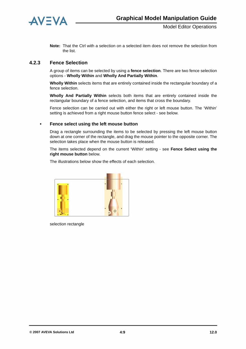
4.2.3 Fence SelectionA group of items can be selected by using a fence selection. There are two fence selectionoptions - Wholly Within and Wholly And Partially Within.
Wholly Within selects items that are entirely contained inside the rectangular boundary of afence selection.
Wholly And Partially Within selects both items that are entirely contained inside therectangular boundary of a fence selection, and items that cross the boundary.
Fence selection can be carried out with either the right or left mouse button. The ‘Within’setting is achieved from a right mouse button fence select - see below.
• Fence select using the left mouse buttonDrag a rectangle surrounding the items to be selected by pressing the left mouse buttondown at one corner of the rectangle, and drag the mouse pointer to the opposite corner. Theselection takes place when the mouse button is released.
The items selected depend on the current ‘Within’ setting - see Fence Select using theright mouse button below.
The illustrations below show the effects of each selection.
selection rectangle
12.0 4:9© 2007 AVEVA Solutions Ltd

Graphical Model Manipulation GuideModel Editor Operations
if Wholly Within is selected
if Wholly And Partially Within is selected
Pressing the Esc key during the drag aborts the selection.
• Fence Select using the Right Mouse ButtonDrag a rectangle surrounding the items to be selected by pressing the right mouse buttondown at one corner of the rectangle, and drag the mouse pointer to the opposite corner. Themenu shown in the picture below appears when the mouse button is released.
12.0 4:10© 2007 AVEVA Solutions Ltd

Graphical Model Manipulation GuideModel Editor Operations
The selection takes place when one of the options on the menu is selected.
Pressing the Esc key during the drag or prior to selecting from the menu aborts theselection. Clicking away from the selection or selecting Cancel on the menu also aborts theselection.
• Adding to an existing Graphical Selection with a fence selectionHolding the Ctrl key down while performing a fence selection adds the selected items to theexisting Graphical Selection.
• Removing selected items from an existing Graphical Selection with a fence selection
Holding the key down while performing a fence selection removes the selected itemsfrom the existing Graphical Selection.
4.2.4 Item-Specific Selection OperationsItem-specific selection operations can be found on some plant items.
12.0 4:11© 2007 AVEVA Solutions Ltd

Graphical Model Manipulation GuideModel Editor Operations
on a Piping Component showing selection options
• Select Pipe and Branch Owners
• Select BranchThe Select BRAN option selects the owning Branch, highlighting it with a green line:
• Select PipeThe Select An Owner>PIPE option selects the owning Pipe, highlighting it with a greenline:
• Select Attached Steelwork SectionsThe Select> options on a Steelwork Section have a similar function to that with PipingComponents.
12.0 4:12© 2007 AVEVA Solutions Ltd

Graphical Model Manipulation GuideModel Editor Operations
If a Section is selected, then Select>SBFR selects all elements in the owningSubframework.
Select >FRMW . . . selects the owning Framework.
4.2.5 Clearing the Graphical SelectionThere are four methods to clear a Graphical Selection:
• Click in blank space in the graphics 3D view.• Select De-Select Current on a selected element in the 3D view.• Select De-Select All on an element in the 3D view. (This is provided for the case where
the 3D view is full, so no part of the 3D view background can be seen.)• Leave Model Editor mode.
4.2.6 Reinstating the Previous Graphical SelectionIf a Graphical Selection has been lost accidentally by clearing the selection or by starting anew selection, the previous selection can be reinstated by selecting Edit>Re-Select fromthe main menu bar.
Leaving Model Editor mode clears the Graphical Selection, but you can reinstate the lastGraphical Selection on return to Model Editor mode by using Edit>Re-Select.
4.2.7 Selection MenuThe Selection menu on the main menu bar contains commands for setting properties of theLocator Handle and the Graphical Selection.
12.0 4:13© 2007 AVEVA Solutions Ltd

Graphical Model Manipulation GuideModel Editor Operations
• Feature HighlightingEnables or disables Feature Identification Mode. Feature Identification Mode is describedin Positioning and Orientation using the Locator Handle.
If the mouse pointer is over a 3D Model Editor view, and the Model Editor is active, pressingthe F key on the keyboard toggles between feature identification mode being switched on oroff.
• Set IncrementsSet Increments shows a form for setting the active movement or rotation increments:
The Linear increment is specified in the currently active units, or units can be specified byusing PDMS units of measure syntax.
• Set Handle ColourAllows you to change the colour of the Locator Handle. The list of available colours is shownon the submenu.
• Drag Image During a drag operation using the Locator Handle, an image of the Graphical Selectionfollows a constrained path defined by the current mouse pointer position. The style offeedback for all items in the Graphical Selection can be selected from the submenu list.
• Select RectangleSets the mode of operation of Select Rectangle on the left mouse button to be WhollyWithin or Wholly And Partially Within.
12.0 4:14© 2007 AVEVA Solutions Ltd
Graphical Model Manipulation GuideModel Editor Operations
4.3 Positioning and Orientation using the Locator Handle
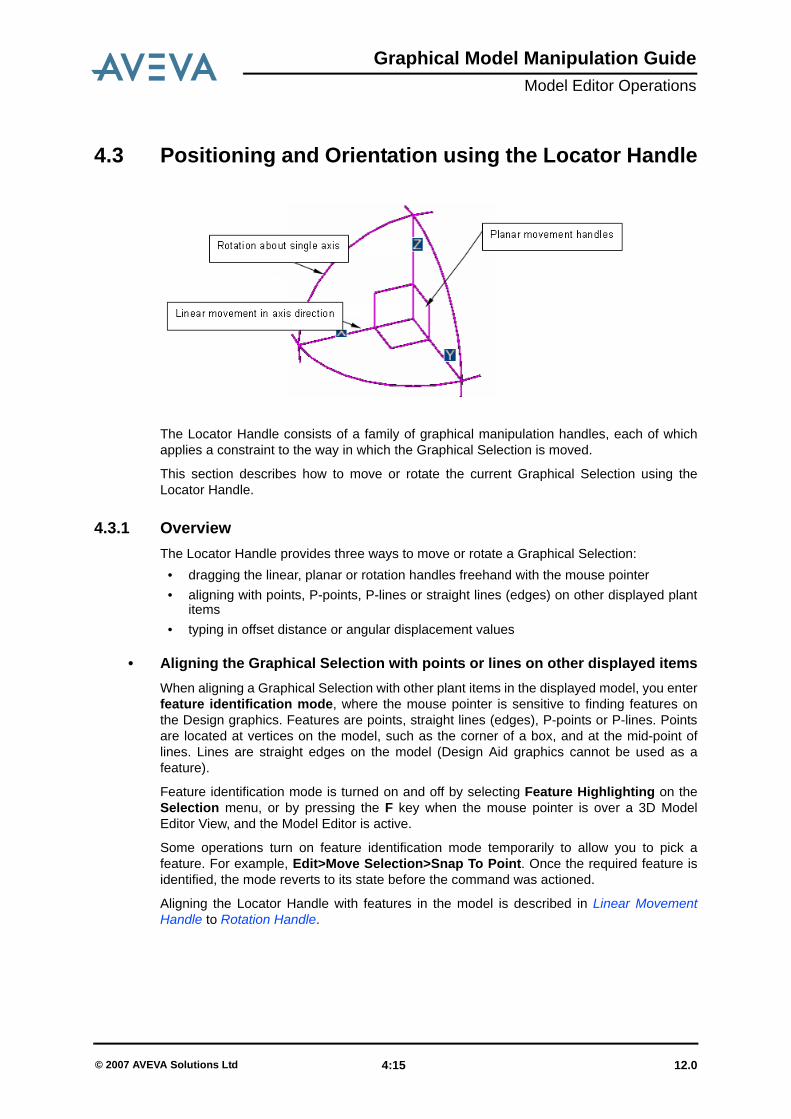
The Locator Handle consists of a family of graphical manipulation handles, each of whichapplies a constraint to the way in which the Graphical Selection is moved.
This section describes how to move or rotate the current Graphical Selection using theLocator Handle.
4.3.1 OverviewThe Locator Handle provides three ways to move or rotate a Graphical Selection:
• dragging the linear, planar or rotation handles freehand with the mouse pointer• aligning with points, P-points, P-lines or straight lines (edges) on other displayed plant
items• typing in offset distance or angular displacement values
• Aligning the Graphical Selection with points or lines on other displayed itemsWhen aligning a Graphical Selection with other plant items in the displayed model, you enterfeature identification mode, where the mouse pointer is sensitive to finding features onthe Design graphics. Features are points, straight lines (edges), P-points or P-lines. Pointsare located at vertices on the model, such as the corner of a box, and at the mid-point oflines. Lines are straight edges on the model (Design Aid graphics cannot be used as afeature).
Feature identification mode is turned on and off by selecting Feature Highlighting on theSelection menu, or by pressing the F key when the mouse pointer is over a 3D ModelEditor View, and the Model Editor is active.
Some operations turn on feature identification mode temporarily to allow you to pick afeature. For example, Edit>Move Selection>Snap To Point. Once the required feature isidentified, the mode reverts to its state before the command was actioned.
Aligning the Locator Handle with features in the model is described in Linear MovementHandle to Rotation Handle.
12.0 4:15© 2007 AVEVA Solutions Ltd

Graphical Model Manipulation GuideModel Editor Operations
• Automatic ScrollingIf the target location for a drag operation is outside of the 3D view, the mouse pointer can bemoved to an edge of the view, where the view will pan automatically up, down, left or rightaccording to the 3D view edge that the mouse pointer hits. The mouse pointer must move inorder for the panning to continue. This may necessitate you making a small movement ofthe pointer near to the view edge to keep the pan operation going.
This technique for panning the view is appropriate for locating a target position that is justout of view.
4.3.2 Linear Movement Handle
The Linear Movement handle allows you to move the Graphical Selection constrained in thedirection of the linear handle axis. The size of each step of the movement is defined by thecurrent movement increment.
Dragging a linear handle with the left mouse button moves the Locator Handle andGraphical Selection in the direction of the linear handle.
To initiate a linear drag, press the left mouse button down over one of the linear movementhandles. With the left button still pressed, moving the mouse drags the Graphical Selectionconstrained in the selected direction, in steps defined by the movement increment.
• Moving one Movement Increment at a TimeIf the movement increment is small relative to the magnification of the 3D view, it can bedifficult to move the mouse freehand to a precise displacement from the Locator Handle’soriginal position. Fine control over positioning can be achieved by dragging with a linearhandle so that it is close to the required position then, while continuing to hold down themouse button, press the plus (+) or minus (-) key on the numeric keypad. This moves theGraphical Selection by one movement increment in the direction of the linear handle if + ispressed, or in the opposite direction if - is pressed.
Using the arrow keys in this way moves the Graphical Selection by 0.1 of the currentmovement increment for each press of the key.
12.0 4:16© 2007 AVEVA Solutions Ltd

Graphical Model Manipulation GuideModel Editor Operations
• FeedbackWhen moving a selection in a constrained direction, the Locator Handle changes to a cut-down version of the full handle to show the direction of movement, as shown below. Thecurrent World position of the Locator Handle is displayed on the status bar, and an offsetfrom the original position of the handle is displayed on the 3D View.
As the mouse moves over a linear handle, the pointer symbol changes to the linear dragpointer.
A Linear Handle has the following movement operations on its shortcut menu:
Enter Valueº
This command shows the following form:
12.0 4:17© 2007 AVEVA Solutions Ltd

Graphical Model Manipulation GuideModel Editor Operations
The field corresponding to the selected axis is activated for input. In this case, entering 2500in the X field tells the Graphical Selection to move by 2500mm in the X direction of theLocator Handle.
Align with Featureº
Repositioning a Graphical Selection to align with a Nozzle using the linear handle andfeature alignment.
This method allows you to position the Graphical Selection in relation to another object onthe screen, but forces the Graphical Selection to move only along the selected axis. Thesequence of operations is as follows:
1. Make a Graphical Selection.Optional: Position the Locator Handle at the required datum position.
2. Select Align with Feature on the linear handle .3. Move the mouse to the target feature. This highlights the target feature, and the mouse
pointer changes shape to indicate that the Graphical Selection will be aligned with thetarget position if the mouse button is clicked.
4. Click the left mouse button to move the Graphical Selection to the target position.
Linear drag can align with a point feature or a line feature.
• Point feature AlignmentWhen positioning the Graphical Selection to a point feature, the origin of the Locator Handleis aligned with the target point such that the target point is projected onto the line ofmovement.
This situation is illustrated below (in two dimensions):
12.0 4:18© 2007 AVEVA Solutions Ltd

Graphical Model Manipulation GuideModel Editor Operations
• Alignment with a Line or P-line FeatureThere are two cases to consider:
• Selected line feature is orthogonal to the line of movement
If the line selected line feature is orthogonal to the line of movement, then the feature line istreated as a feature point. Any position along the feature line projects onto the same pointon the movement line.
• Selected line feature not orthogonal to the line of movement
If the line selected line feature is not orthogonal to the line of movement, then theintersection of the extended feature line with the line of movement becomes the newLocator Handle origin position. If the extended feature line and the movement line do notintersect in 3D, then the point chosen is the nearest point on the line of movement to theextended feature line.
This situation is illustrated below (in two dimensions):
• Alignment with a P-point FeatureThere are two cases to consider:
• P-point as point feature
A P-point feature may be treated as a point feature, and works as described above forpoints.
• P-point as a Line feature
A P-point has a direction, which is indicated by the arrow on a P-point feature symbol. If themouse pointer is moved over the P-point arrow, then the intersection of the P-point directionwith the line of movement becomes the new Locator Handle origin position. If the P-pointdirection and the movement line do not intersect in 3D, then the point chosen is the nearestpoint on the line of movement to a line projected from the P-point position in the P-pointdirection.
The following pictures illustrate the difference between P-point as a point and P-point as aline:
12.0 4:19© 2007 AVEVA Solutions Ltd

Graphical Model Manipulation GuideModel Editor Operations
Mouse over P-point position
12.0 4:20© 2007 AVEVA Solutions Ltd

Graphical Model Manipulation GuideModel Editor Operations
Mouse over P-point arrow
Snap To Point
Snap To Point allows the Graphical Selection to be moved to a Point feature. The GraphicalSelection is not constrained to move along the direction of the Linear Handle. This isdescribed in Positioning and Orientation Using the Edit Menu.
Move Handle
The Move Handle submenu provides the same movement commands as the main LinearHandle menu, but these commands move the Locator Handle only. They do not move theGraphical Selection.
12.0 4:21© 2007 AVEVA Solutions Ltd

Graphical Model Manipulation GuideModel Editor Operations
The Locator Handle may be moved independently of the Graphical Selection in order tochange the datum position for the next operation on the Graphical Selection.
4.3.3 Planar Movement HandlesEach of the planar movement handles constrains the drag operation such that the GraphicalSelection moves only in the plane of the selected handle. The handle moves in stepsdetermined by the current Movement Increment setting.
To initiate a planar drag, you press the left mouse button down over one of the planarmovement handles. With the left button still pressed, moving the mouse drags the GraphicalSelection constrained in the selected plane, in steps defined by the movement increment.
• FeedbackA triangle is displayed on the current constraint plane, between the original position of thehandle and the current position. The relative movement distances are shown on the sides ofthe triangle. The current World position of the Locator Handle is displayed on the status bar.All values are shown in the current selected units.
The Locator Handle changes to a simple version of the full handle to show the plane ofmovement as shown below.
As the mouse moves over a planar handle the pointer symbol changes to the planar dragsymbol.
A Planar Handle has the following movement operations on its shortcut menu:
12.0 4:22© 2007 AVEVA Solutions Ltd

Graphical Model Manipulation GuideModel Editor Operations
Enter Valuesº
This command shows the following form.
The fields corresponding to the selected plane are activated for input. In this case, entering8000 in the X field and 4000 in the Z field tells the Graphical Selection to move by X8000mmZ4000mm in the XZ plane of the Locator Handle.
Align with Feature…
This facility allows you to position the Graphical Selection in relation to another object on thescreen, but forces the Graphical Selection to move only in the selected plane. Thesequence of operations is as follows:
1. Make a Graphical Selection.Optional: Position the Locator Handle at the required datum position.
12.0 4:23© 2007 AVEVA Solutions Ltd

Graphical Model Manipulation GuideModel Editor Operations
2. Select Align with Feature… from the planar handle.3. Move the mouse to the target feature. A marker appears at the target point, and the
mouse pointer changes shape to indicate that the Graphical Selection will be alignedwith the target position if the left mouse button is clicked.
4. Click the left mouse button to move the Graphical Selection to the target position.
• Point feature AlignmentWhen positioning the Graphical Selection to a point feature, the origin of the Locator Handleis aligned with the target point such that the target point is projected onto the plane ofmovement. For example, the picture above shows the target P1 P-point position beingprojected onto the plane of movement of the Graphical Selection.
• Alignment with a Line or P-line FeatureIf a planar move is to be aligned with a line feature, then the Locator Handle origin is placedwhere the extended feature line or P-point direction intersects with the movement plane. Forexample, in the following picture, the handrail is dragged in a horizontal plane, with thebottom of the first post positioned where the top of the stringer intersects with the plane. Thefeature selected is an edge on the top of the stringer.
Snap To Pointº
Snap To Point… allows the Graphical Selection to be moved to a Point feature. TheGraphical Selection is not constrained to move in the plane of the Linear Handle. This isdescribed in Positioning and Orientation Using the Edit Menu.
12.0 4:24© 2007 AVEVA Solutions Ltd

Graphical Model Manipulation GuideModel Editor Operations
Move Handle
The Move Handle submenu provides the same movement commands as the main PlanarHandle menu, but these commands move the Locator Handle only. They do not move theGraphical Selection.
The Locator Handle may be moved independently of the Graphical Selection in order tochange the datum position for the next operation on the Graphical Selection.
4.3.4 Rotation Handle
The rotation handles allow you to rotate the Graphical Selection around the relevant axisusing the current angular increment to control the angular step size.
Dragging a Rotation handle with the left mouse button rotates the handle and the GraphicalSelection about the axis of rotation. To perform a rotation, press the left mouse button overthe relevant rotation handle. With the left button still depressed, drag the mouse to performthe rotation.
12.0 4:25© 2007 AVEVA Solutions Ltd

Graphical Model Manipulation GuideModel Editor Operations
• Feedback
The angular movement from the original orientation is shown as the Locator Handle isrotated. The angular displacement is also shown in the status bar.
As the mouse moves over a rotation handle, the pointer symbol changes to the rotation dragsymbol, and half of the Rotation Handle arc changes to show two arrows. This feedbackindicates which of the axes will be aligned with a feature when feature alignment is used.
• Rotation Handle A Rotation Handle has the following movement operations on its shortcut menu:
Enter Valueº
This allows the Graphical Selection to be rotated about one of the Locator Handle axes.
12.0 4:26© 2007 AVEVA Solutions Ltd

Graphical Model Manipulation GuideModel Editor Operations
Orient to Point
Rotating an elbow to align with a Nozzle using a rotation handle and feature alignment
The sequence of operations is as follows:
1. Make a Graphical SelectionOptional: Position the Locator Handle at the required datum position
2. Select Orient to Point… from the Rotation handle Move the mouse to the target point. The mouse pointer changes to indicate that a pointhas been located, and the axis is directed towards the point.Click the primary mouse button to rotate the Graphical Selection to the targetorientation.
12.0 4:27© 2007 AVEVA Solutions Ltd

Graphical Model Manipulation GuideModel Editor Operations
Align with Direction
Rotating a pump to align with a flange using a rotation handle and feature alignment
The sequence of operations is as follows:
1. Make a Graphical SelectionOptional: Position the Locator Handle at the required datum position
2. Select Align with Direction… from the Rotation Handle .3. Move the mouse to the target line (edge) or P-point direction. The mouse pointer
symbol changes to indicate that the axis will be directed parallel to the edge. If theGraphical Selection is shown 180 degrees out of alignment, press the key to getthe alternate alignment. On a P-point, this can be achieved by choosing one of thearrows on the P-point feature.
4. Click the left mouse button to rotate the Graphical Selection to the target orientation.
Align with
Rotates the selection until the chosen axis points in the given direction. The GraphicalSelection is rotated about one of the Locator handle axes, such that the chosen axis pointsas close to the direction specified as possible.
12.0 4:28© 2007 AVEVA Solutions Ltd

Graphical Model Manipulation GuideModel Editor Operations
Rotate Handle
The Rotate Handle submenu provides the same rotation commands as the main RotationHandle menu, but these commands rotate the Locator Handle only. They do not rotate theGraphical Selection.
The Locator Handle may be rotated independently of the Graphical Selection in order tochange the frame of reference for the next operation on the Graphical Selection.
Rotate Handle>To World
This command aligns the Locator Handle with the World co-ordinate system, withoutrotating the Graphical Selection. The Locator Handle Y axis points North, and the Z axispoints Up.
4.3.5 Feature HighlightingHaving made a graphical selection in Model Editor mode, use Selection>FeatureHighlighting to switch into a mode where features are identified as the mouse pointerpasses over them on a 3D view. If Feature Highlighting is on, selecting it again switchesfeature snapping off. Alternatively, the F key can be used to toggle feature identification onand off if it is pressed over the 3D View while in Model Editor mode.
If the Graphical Selection is dragged using the Locator Handle while FeatureHighlighting is on, it aligns itself with key features on the displayed model as the mousepointer passes over them. See the sections on Linear, Planar and Rotation Handles for adescription of how feature highlighting works for each handle.
There is an alternative method to select a feature. Moving the mouse over the 3D modelwithout dragging the locator handle still highlights features. Pressing the right mouse buttonover a highlighted feature shows a menu that allows the Graphical Selection or the LocatorHandle to be moved to the selected position.
12.0 4:29© 2007 AVEVA Solutions Ltd

Graphical Model Manipulation GuideModel Editor Operations
for a point feature while in feature identification mode
Selecting Move Handle Here in the picture above moves the handle to the selected point.
In order to select features of an item, it is necessary to move the mouse pointer over theitem before features are shown. In most cases, the target P-point or P-line lies on, or inside,an item, so selecting a feature is straightforward. In the few cases where the P-point or P-line is outside of the item, or partly obscured by another item in the scene, it is necessary tomake sure that the mouse pointer first passes over the associated item.
On steelwork items with P-lines, the JUSL P-line is shown as a feature.
Feature identification:• The Locator Handle can be moved to features on selected or unselected items.• The Graphical Selection cannot be moved to a reference point on selected items,
because the selected items are shown in their new location when a reference point isfound.
• Cancelling the DragAt any point of the move, you can cancel the drag operation by pressing the Esc key. This isa standard way of cancelling a drag operation on Windows. When the drag is cancelled theselection reverts to its original position and remains selected.
12.0 4:30© 2007 AVEVA Solutions Ltd

Graphical Model Manipulation GuideModel Editor Operations
4.3.6 Moving the Locator Handle Independently of the Graphical SelectionA Locator Handle can be moved independently of the Graphical Selection. This allows adatum position to be set for subsequent move operations, or an axis of rotation to be set forsubsequent rotation operations.
The Locator Handles and the Edit menu provide commands for moving and rotating theLocator Handle on its own. In order to drag the Locator Handle without the GraphicalSelection, select the linear, planar or rotation handle by pressing the left mouse buttondown, and then press the H key on the keyboard. This detaches the Locator Handle fromthe Graphical Selection. The H key can be used to toggle between moving the LocatorHandle on its own, and moving the Graphical Selection with the Locator Handle.
4.4 Positioning and Orientation Using the Edit Menu
4.4.1 Move Selection and Move Handle
Move Selection moves the Graphical Selection. Move Handle moves the Locator Handleonly. The three operations described below apply to both Move Selection and MoveHandle.
• Move Selection/Handle>Offset in 3D…
12.0 4:31© 2007 AVEVA Solutions Ltd

Graphical Model Manipulation GuideModel Editor Operations
The Graphical Selection can be moved relative to its original position, in the co-ordinatesystem of the Locator Handle. The position of the Graphical Selection only changes if OK isclicked.
• Move Selection/Handle Set 3D Position…
This form shows the current position of the Locator Handle in World co-ordinates. Changingthe settings and clicking OK moves the selection to the specified world co-ordinates.
• Move Selection/Handle>Snap to Point
12.0 4:32© 2007 AVEVA Solutions Ltd
Graphical Model Manipulation GuideModel Editor Operations
Repositioning an Equipment to align with the centre of a SCTN
This facility allows you to position the Graphical Selection at a selected position in relation toanother object on the screen. The sequence of operations is:
1. Add one or more plant items into a Graphical SelectionOptional: Position the Locator Handle at the required datum position
2. Select Move Selection/Handle>Snap to Point from the Edit menu3. Move the mouse pointer to the target position. The pointer changes to indicate that the
Graphical Selection will snap to the target feature4. Click the left mouse button to move the Graphical Selection to the target position.
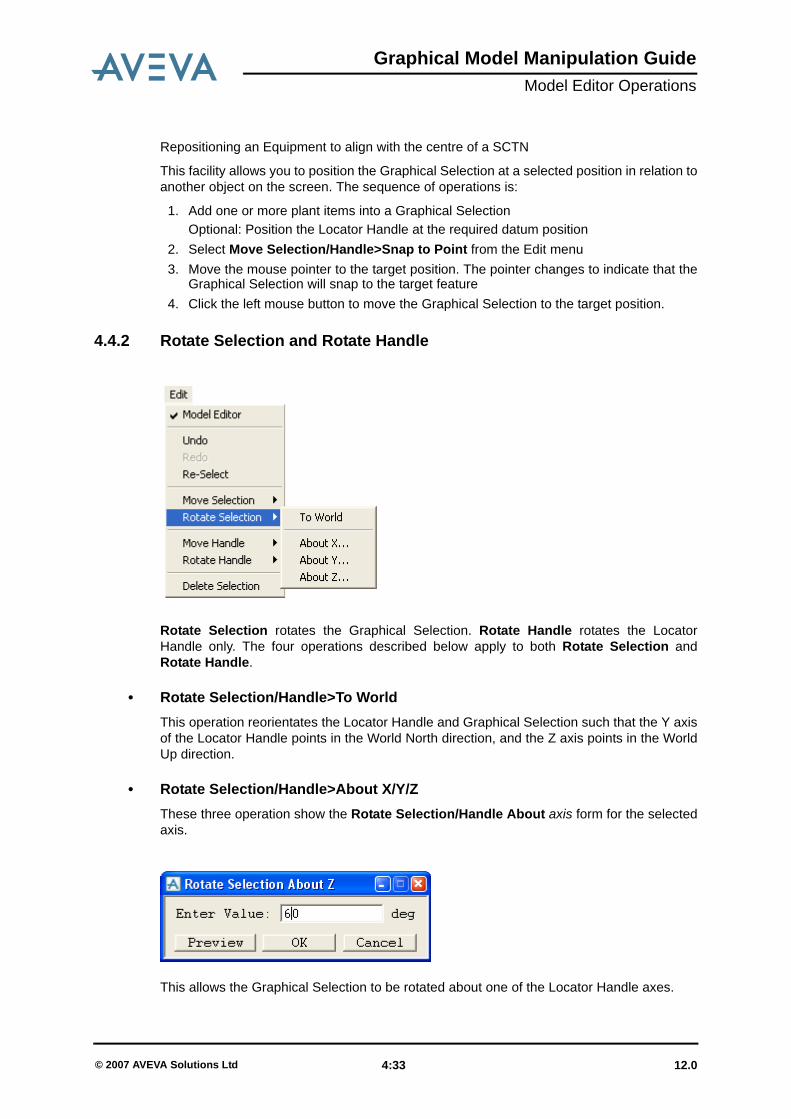
4.4.2 Rotate Selection and Rotate Handle
Rotate Selection rotates the Graphical Selection. Rotate Handle rotates the LocatorHandle only. The four operations described below apply to both Rotate Selection andRotate Handle.
• Rotate Selection/Handle>To WorldThis operation reorientates the Locator Handle and Graphical Selection such that the Y axisof the Locator Handle points in the World North direction, and the Z axis points in the WorldUp direction.
• Rotate Selection/Handle>About X/Y/ZThese three operation show the Rotate Selection/Handle About axis form for the selectedaxis.
This allows the Graphical Selection to be rotated about one of the Locator Handle axes.
12.0 4:33© 2007 AVEVA Solutions Ltd
Graphical Model Manipulation GuideModel Editor Operations
4.5 Clipping
4.5.1 Clipping SubmenuClipping lets you display only those parts of the model which fall inside a clipping box. TheClipping submenu is displayed by right-clicking on the Clipping & Options icon on the 3DView toolbar. The options available from this menu are:
Enable
Controls whether the clipped model or the whole model is displayed. The default is forclipping to be off.
Capped
When you use clipping, only the parts of the model which lie within the clipping box will bedisplayed. Where items are intersected by the clipping box, they can have a coloured capadded to show that they extend beyond the displayed region. Note that this feature is notavailable on all graphics cards.
To control whether or not caps are added, set Cap on or off. The default is for capping to beoff.
Colour...
To change the colour used for capping, select the required colour from the displayed ClipCap Colour form.
CE
Sets the clipping box to the current element.
Owner
Sets the clipping box to the owner of the current element.
Limits Box
Sets the clipping box to the dimensions of your explicitly defined Limits Box.
Pick Item
Sets the clipping box to the element you select from the 3D View.
Pick Limits
Lets you specify the extent of the clipping box by constructing a box between two pointsidentified by picking on the displayed graphics. Positioning options for picking are controlledusing by selecting from the options on the Positioning Control form.
Explicit
Selecting the Explicit... option displays the Clip - 3D View and Positioning Control forms.If a clipping box has previously been defined its dimensions and origin are shown on theClip - 3D View form; if not, a default sized box is placed at the origin of the view. The currentsettings for the box are shown in the 3D View as a box, in the default aid line colour.
These forms allow you to define a new clipping box by either:
12.0 4:34© 2007 AVEVA Solutions Ltd

Graphical Model Manipulation GuideModel Editor Operations
• Entering the dimensions and co-ordinates of the origin (centre) directly into the text-boxes on the Rotate - 3D View form. You can use the drop-down list boxes to set theNorth/South, East/West and Up/Down axes as necessary.
• Entering the dimensions, directly into the text-boxes on the Rotate - 3D View form, andthen picking the required origin in the 3D View, using the EDG facilities. You can firstselect the type of item to be picked and the mode the software will use to derive thepoint, on the Positioning Control form.
and then clicking Apply.
You can also change the orientation of the clipping box, by defining a plane through which itpasses. The icon buttons at the top of the Orientation frame allow you to define a plane bypicking either three explicit points or two points, the third point is taken as the currentworking plane. Alternatively, you can edit the Y is and Z is test boxes, to set the orientationof the clipping box.
To extend the clipped volume by a specific amount, enter a number into the Extend ClippedVolume by gadget.
Dismiss the forms when you are satisfied with the settings.
You must also select the Enable menu option to make the setting take effect in the view.
Planes
Allows up to six individual planes to be defined to clip the model - see Six-Plane Clipping.
4.5.2 Six-Plane ClippingAs an alternative to the clipping box, up to six individual planes may be defined to clip themodel. The planes may be aligned on plant items such as panels and beams, or byselecting ship grid lines.
The 6-plane clipping feature and the clipping box are mutually exclusive. Enabling one hasthe effect of disabling the other and clearing any related forms and aid graphics.
Clipping planes can be at any angle, for example to suit tapered compartments on a ship.Up to six planes can be defined, and the direction of a plane is considered to point into theregion of interest.
Right-clicking on the Clipping & Options icon on the 3D View toolbar and selecting thePlanes option displays the Clip - 3D View form.
12.0 4:35© 2007 AVEVA Solutions Ltd

Graphical Model Manipulation GuideModel Editor Operations
The Define Clipping Plane drop-down list is used to select the plane (1-6) to be defined.
The Position drop-down list and data entry fields are used to set the position of the selectedplane.
The Direction field is used to set the direction (e.g. E for East).
Clicking the Pick button enables a clipping plane to be aligned, for example, on a plant itemsuch as a panel or beam, which is picked from the 3D View. The system will thenautomatically fill in the Position and Direction fields based on the position and orientation ofthe picked item.
The Reverse direction button is useful where a deck plate is picked and the view must beabove or below it.
Once the plane position and direction have been obtained from the picked item, the planecan be enabled, using the Enabled plane button.
The clipped volume can then be finely adjusted if necessary by using the gadgets at thebottom of the form to slide the selected plane in or out.
12.0 4:36© 2007 AVEVA Solutions Ltd

Graphical Model Manipulation GuideModel Editor Operations
Planes can be automatically defined based on the clipping box, e.g. following clip CE, thenadjusted individually. Planes can also be defined by selecting grid lines from a grid system.In this case, select Derive 6 planes from grid lines from the Tools menu on the Clip - 3DView form:
The Clip From Grid form is displayed:
The Grid Systems list shows the available grid systems for the project. When one of theseis selected, the lower half of the form will change to reflect the grid system selected.
Individual grid lines to delimit the clipped volume can be selected from the Limits From andTo drop-down option lists, or the nearest grid lines to two picked positions can beautomatically selected using the two Pick buttons. Positive or negative offsets (in mm)relative to the grid lines can be entered into the +/- boxes.
After selecting/picking the grids, the defined volume will be marked graphically:
12.0 4:37© 2007 AVEVA Solutions Ltd

Graphical Model Manipulation GuideModel Editor Operations
The positions of the clipping planes will be automatically entered into the form in terms ofgrid lines and offsets:
When the Apply button is pressed, the clipping planes are applied to the view:
12.0 4:38© 2007 AVEVA Solutions Ltd

Graphical Model Manipulation GuideModel Editor Operations
To assist in selecting the appropriate grid lines for clipping, any position can be picked todisplay it in World and Grid Coordinates. Select Picked position in grid coords... from theDisplay menu on the Clip From Grid form: the Display Grid Coords form is displayed.
12.0 4:39© 2007 AVEVA Solutions Ltd

Graphical Model Manipulation GuideModel Editor Operations
4.6 Undo and Redo
The ease with which you can manipulate the model using the graphical techniques providedin DESIGN makes the provision of an ‘undo’ facility a natural requirement.
There are three types of activity that are recognised while you are in Model Editor mode.For each of these, the current state is saved before the change in order that it may berestored by a subsequent Undo.
Changes to the database as a result of manipulating the Graphical Selection either by directgraphical manipulation or from the context sensitive menus can be undone. (The selectionset and the position/orientation of the Locator Handle are also restored.)
There are two ways you may undo an activity:
• Using the standard Undo and Redo icons ( ) in the main toolbar.
• Using the Undo and Redo options on the Edit pull-down menu.
You may step back through undo states one at a time. Following an undo, you can thenchoose to redo the sequence, stepping forward one state at a time until the sequence ofchanges that were undone are restored. If you do one or more "undos" and then save anew state, the redo option is no longer available and the corresponding icons/menu optionsbecome inactive.
Switching between applications in Design causes the Modify mode button to be switched offand the undo/redo states to be re-initialised.
Note: Undo/Redo operations can also take place outside of Model Editor Mode. If the Undooperation involves moving into or out of Model Editing mode, then the switch into thatmode happens automatically, and the Model Editor button and menu option willreflect the change. The selection set and handle appropriate to the editing operationthat was being used are also restored. Other ‘undoables’ (operations or sequences of operations that can be undone) canbe defined as a PML ‘undoable object’ - see the VANTAGE Plant Design SoftwareCustomisation Guide.
12.0 4:40© 2007 AVEVA Solutions Ltd

Graphical Model Manipulation GuideModel Editor Operations
4.7 Delete SelectionDelete Selection on the Edit menu deletes from the database all items in the GraphicalSelection. This operation is only available while a Graphical Selection exists.
Note: You will be asked to confirm the deletion.
4.8 Selectable ItemsThe following table lists element types that can be selected and modified using the ModelEditor. Note that some types of element can be modified if they belong to an administrativeelement such as a ZONE or FRMW, but they cannot be individually modified if they belongto a Plant Item. For example, A SCTN element can be selected and moved if it belongs to aFRMW or SBFR element, but not if it belongs to a TMPL element.
Plant Item Selectable Elements
EQUIPMENT SITE>ZONE>EQUI
PIPE (and CABLE TRAY)
PIPE/CABLE TRAY SITE>ZONE>PIPE using the Select Owners operation
BRANCH SITE>ZONE>PIPE>BRAN using Select Ownersoperation
Pipe component SITE>ZONE>PIPE>BRAN>(any component)
HVAC
HVAC SITE>ZONE>HVAC using Select Owners operation
BRANCH SITE>ZONE>HVAC>BRAN using Select Ownersoperation
HVAC component SITE>ZONE>HVAC>BRAN>(any component)
HANGERS
RESTRAINT …PIPE>REST & …HVAC>REST using Select Ownersoperation
HANGER …PIPE>REST>HANG & …HVAC>REST>HANG
PIPE TRACK SITE>ZONE>PTRA
ROUTING PLANE SITE>ZONE>RPLA or SITE>ZONE>STRU>RPLA
RPLA also exists under EQUI, PTRA, SUBE, SUBS -RPLA is NOT a significant element in these situations
PENALTY VOLUME SITE>ZONE>PVOL or SITE> ZONE>STRU>PVOL
Note: PVOL also exists under EQUI, PTRA, SUBE,SUBS - PVOL is not a significant Model Editorelement in these situations
STRUCTURES
12.0 4:41© 2007 AVEVA Solutions Ltd

Graphical Model Manipulation GuideModel Editor Operations
Note: The Model Editor does not work with Design Template elements in the TemplateWorld. It is not possible to selected elements owned by a TPWL>TMAR>TMPLhierarchy.
Primitive owned directly bySTRU
SITE>ZONE>STRU>(Primitive)
SUBSTRUCTURE SITE>ZONE>STRU>SUBS
FRAMEWORK …STRU>FRMW using Select Owners operation
SUBFRAMEWORK …STRU>FRMW>SBFR using Select Owners operation
Collection of FLOOR …STRU>FRMW>CFLOOR using Select Ownersoperation
Collection of WALL …STRU>FRMW>CWALL using Select Ownersoperation
Collection of SCREED …STRU>FRMW>CSCREED using Select Ownersoperation
Note: The following elements may be owned by FRMW, SBFR, CFLOOR, CWALL orCSCREED
GENSEC GENSEC
WALL WALL
PANEL PANE
FLOOR FLOOR
GWALL GWALL
SCREED SCREED
PNODE PNOD
SCTN SCTN
STWALL STWALL
PALJ PALJ
DRAW SITE>DRAW or SITE>ZONE>DRAW
Note: DRAW also exists under EQUI, PTRA, SUBE,SUBS - DRAW is NOT a significant element inthese situations. See selection rules for thoseelement types
BOUNDARY SITE>BOUN or SITE>ZONE>BOUN
GROUND MODEL SITE>GRDM
DATUM SITE>ZONE>DATU
Plant Item Selectable Elements
12.0 4:42© 2007 AVEVA Solutions Ltd

Graphical Model Manipulation GuideGraphical Equipment Modification
5 Graphical Equipment Modification
5.1 Introducing Graphical Equipment ModificationEntering Model Edit mode, clicking on an Equipment Item and selecting Edit Equipmentfrom the shortcut menu enables the Graphical Equipment Modification (GEM) facilities.
GEM gives menu options which facilitate the graphical modification of an Equipment itemand its ‘offspring’, down to primitive level.
12.0 5:1© 2007 AVEVA Solutions Ltd

Graphical Model Manipulation GuideGraphical Equipment Modification
5.2 Equipment Modification Characteristics and Facilities
5.2.1 Display CharacteristicsSelecting an Equipment item and enabling GEM makes non-Equipment items in the displaytranslucent. For example:
Clicking on a primitive which itself contains primitives causes the other Equipment primitivesto become translucent. Negative primitives are drawn in wireline.
12.0 5:2© 2007 AVEVA Solutions Ltd

Graphical Model Manipulation GuideGraphical Equipment Modification
5.2.2 Modification FacilitiesElements below the hierarchical level of a selected primitive can be accessed using the Edit<primitive> shortcut menu selection (for example Edit BOX).
Elements below the hierarchical level of a selected primitive can now be selected andmanipulated using the standard facilities, see Model Editor Operations.
To exit GEM, select Exit Equipment Editor from the shortcut menu.
12.0 5:3© 2007 AVEVA Solutions Ltd

Graphical Model Manipulation GuideGraphical Equipment Modification
12.0 5:4© 2007 AVEVA Solutions Ltd

Graphical Model Manipulation GuideGraphical Component Modification
6 Graphical Component Modification
6.1 Introducing Graphical Component ModificationGraphical Component Modification (GCM) enables you to use the mouse to move androtate a Component or a selection of contiguous Components within the constraints of apipe route.
GCM is entered automatically when you click on a piping Component while in Model Editormode. You do not have to be in the Design Pipework application to be able to use thisfacility, which enables you to move interactively a Component along the legs of a pipe routeand to rotate a Component about the tube centreline.
The Movement Handle in this case appears as show below:
The following facilities and constraints are available:• rotation about the tube centre line• constrained positioning along the path of the pipe route:
• increment snapping
12.0 6:1© 2007 AVEVA Solutions Ltd

Graphical Model Manipulation GuideGraphical Component Modification
• feature highlighting• Components can only be repositioned where there is sufficient space to fit them in the
route• automatic reorder of the elements within the hierarchy to suit the new position within
the pipe route• the ability to reposition the handle within the constraints of the Component selection set
(along the centreline of the pipe)• the initial orientation of a selection should be maintained where possible • undo/redo changes.
The system does not try and resolve any inconsistencies that may occur from therepositioning of a Component. For example if a Reducer is moved into another leg of aBranch, the Components and tube between the Reducer’s original position and its newposition in the Branch remain the same.
Note: in the above case, if a Component is moved across a Reducer, the Component isnot automatically reselected from the Specification; this must be done ‘manually’.
GCM is enabled automatically by first entering Model Edit mode and then selecting of aPiping Component or a sequential set of Components which are within the same leg of aPipe Branch, and provided the selection set has certain characteristics.
GCM is exited either by leaving Model Edit mode or by selecting another element thatbreaks the rules for displaying the Component Modification handle.
6.2 Selection Set for GCM(See Selection for general information about Selection.) The movement handle is onlyshown when the selection set contains:
• A single Piping Component which does not cause the Branch to change direction, i.e.the Component has a parallel Arrive and Leave direction:
• A sequential set of Piping Components which lie within the same leg of a Branch, i.e.there is no change in direction or a bad alignment exists in the leg:
• In the following example the Component Modification Handle is not displayed.
12.0 6:2© 2007 AVEVA Solutions Ltd

Graphical Model Manipulation GuideGraphical Component Modification
• In this example the Component Modification Handle is displayed
6.2.1 Component Modification HandleThe Component Modification Handle only appears where the selected Component(s)conform to the rules as defined above.
By default the origin of the initial Component identified to define a selection is used toposition the handle.
Picking a Component already within the selection set moves the handle to the origin of theidentified element:
12.0 6:3© 2007 AVEVA Solutions Ltd
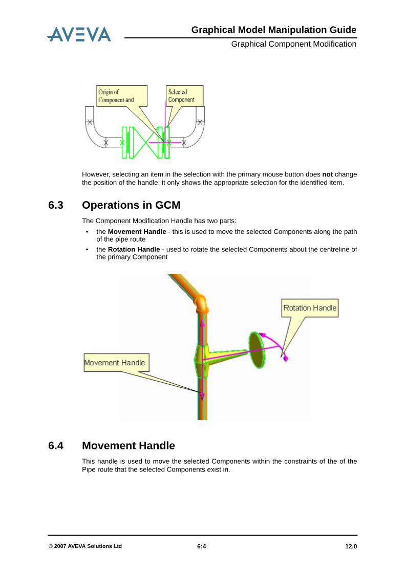
Graphical Model Manipulation GuideGraphical Component Modification
However, selecting an item in the selection with the primary mouse button does not changethe position of the handle; it only shows the appropriate selection for the identified item.
6.3 Operations in GCMThe Component Modification Handle has two parts:
• the Movement Handle - this is used to move the selected Components along the pathof the pipe route
• the Rotation Handle - used to rotate the selected Components about the centreline ofthe primary Component
6.4 Movement HandleThis handle is used to move the selected Components within the constraints of the of thePipe route that the selected Components exist in.
12.0 6:4© 2007 AVEVA Solutions Ltd

Graphical Model Manipulation GuideGraphical Component Modification
6.4.1 DraggingThe handle can be dragged by using either using primary or secondary mouse buttons. Thelegs that the selection can be dragged into are highlighted with a turquoise line (see abovefigure). By default, the handle moves in multiples of the currently defined linear increments- see Element Selection in the Model Editor.
When dragging using the secondary mouse button, you are presented with a context-sensitive menu on button up. The menu displays the available options which relate to thedrag and when in a special action mode (e.g. feature highlighting, see Feature Highlighting),the target, if applicable. If no special actions are active, you are given the option to acceptthe new position or cancel the operation and the handle and selection return to their originalposition.
6.4.2 Feature HighlightingWith Feature Highlighting ‘on’, dragging with the primary mouse button held down causesfeatures such as p-points or p-lines to be highlighted when the pointer moves across them.Highlighted features can then be ‘snapped' to. Feature highlighting can be activated eitherfrom the F ‘hotkey’ or from Selection>Feature Highlighting on the main menu bar.
As the alignment with a feature invariably relates to the leg the Components are in, whenfeature highlighting is active the drag movement is constrained to lie along the leg theselected Component is currently in, not the whole pipe route. This prevents the inadvertentrepositioning of Components into a different leg when trying to align with a feature.
When no feature is found initially, the handle moves using the default movement incrementsuntil a feature is identified. Selected Components cannot moved past either end of the pipeleg they are within.
Where a derived position is not within the bounds of the leg or cannot physically fit within asegment of a leg, the selected Components are positioned at the nearest extent of the legclosest to the derived position. Feedback is given to indicate that the positions of the itemsare not in alignment with the identified feature.
Where there is more than one position solution, the system has default behaviour to derivethe initial position (see Feature Highlighting for further details). However, it is possible tocycle through the possible positions and choose the desired one. The P hotkey is used forthis.
12.0 6:5© 2007 AVEVA Solutions Ltd

Graphical Model Manipulation GuideGraphical Component Modification
Subsequent feature identification within the same drag uses the last solution type to derivethe position, where possible. If there is no position solution to the feature selection, thesystem reverts to its default behaviour.
6.4.3 Nudging the HandleOnce a drag has been started using the primary or secondary mouse button, you can finelyadjust the positioning of the selected Components using hotkeys. You can ‘nudge’ themanipulation handle when dragging in a linear direction, using the numeric keypad + and -keys. This moves the handle by + or - the current linear increment.
In a similar way to nudging a Component you may nudge the position of the handle both bythe default linear increment for major positioning, and by a fine value for accuratepositioning (e.g. clearance from surfaces). To facilitate this a ‘fine nudge’ setting is available,where the granularity of the movement is less than that of the current linear increments.
Linear increments are controlled from the Set Increments form, see the PDMS Designonline help for details.
Similar to the nudging using the + and - hotkeys, the fine adjustment uses the arrow keys onthe numeric keypad (or the numeric keypad 2 and 8 keys when Num Lock is ‘off’.
Once a nudge has been performed, then dragging has no effect, but the mouse key must bekept held down. Nudging restricts the movement within bounds of the leg or segment of legthat the selected Components are within. Nudging does not take the selected Componentspast an inline Component or change in direction.
12.0 6:6© 2007 AVEVA Solutions Ltd

Graphical Model Manipulation GuideGraphical Component Modification
6.5 Rotation HandleThe Rotation Handle allows you to rotate interactively the selected Components about thecentreline of the Pipe that the handle is positioned on.
6.5.1 DraggingThe Rotation Handle (and the graphical selection it is attached to) can be dragged by eitherthe primary or secondary mouse buttons, and allows a full 360° rotation about the centrelineof the pipe. The legs that the selection can be dragged into are highlighted with a turquoiseline (see above figure).
Dragging the handle with the secondary mouse button is the same as using the primarymouse button, but presents you with a context-sensitive menu which relates to the directionand rotation of the handle, see Popup Menus on the Component Modification Handle.
12.0 6:7© 2007 AVEVA Solutions Ltd

Graphical Model Manipulation GuideGraphical Component Modification
6.5.2 Feature HighlightingUse of Feature Highlighting with the Rotation Handle is similar to using Feature Highlightingwith the Movement Handle, see Feature Highlighting.
When performing a free rotate, if feature highlighting is active but no feature is identified, therotation uses the currently defined angular increment value. When a feature is identified, thehandle is aligned in the appropriate manner, dependent on the feature identified. See PopupMenus on the Component Modification Handle and Hotkeys for details of shortcut menu andhotkey options available when manipulating the rotation handle.
6.5.3 Nudging the HandleOnce a drag has been started using the primary or secondary mouse button, you can adjustthe derived angular offset using the + and - hotkeys for the rotation handle.
As with moving, if a direction is derived from an alignment with a feature, using the nudgeincrements the rotation from the derived direction.
The Rotation Handle can be ‘nudged’ in the same way as the Linear Handle, see Nudgingthe Handle.
6.5.4 Repositioning the HandleThe default position of the Rotation Handle is at the origin of the Component initiallyselected when defining the selection. Identifying another Component in the selectionrepositions the handle to the origin of the identified item.
In some instances you may wish to reposition the handle at a position which does notcorrespond to the origin of a Component. You can reposition the handle to the extremities ofthe selected Components via a pop-up menu on the movement handle:
12.0 6:8© 2007 AVEVA Solutions Ltd

Graphical Model Manipulation GuideGraphical Component Modification
6.6 Movement and Rotation Characteristics
6.6.1 Movement HandleYou can reposition the selected Components freely along the route of the pipe Branch intoany segment where the Components can fit. All selection and handle movements can beundone and redone using the Undo/Redo buttons.
The following rules are for where the selected Components can be positioned within a route:
1. There must be enough implied tube for the selected Components to be positioned in.
Where there is tube adjacent to the selected Components, then the length of theselected Components and the adjacent tube is taken to be a continuous segment.
2. The tube between two adjacent Components must parallel to the Arrive and Leavedirections of the adjacent Components.
(Arrive of Selection)
(Leave of Selection)
12.0 6:9© 2007 AVEVA Solutions Ltd

Graphical Model Manipulation GuideGraphical Component Modification
As the repositioning of Components does not reselect the adjacent Components orelements, this allows for the instances where the selected Components are included into asegment of pipe which has a different bore, but which still allows the Components to bemoved.
By default where there are no obstructions or changes of directions within a line, theComponents being moved will move using the currently defined linear increments.
When an extremity of the selection of Components is coincident with or passes theapproach side of an obstruction or change in direction (i.e. a Bend or Elbow), the leadingextremity of the selection snaps to the approach of the obstruction.
Where a selection is snapped to a Component, feedback is given to inform you that this hastaken place.
Where the selection has snapped to an obstruction or change in direction, the movementwill stop until the pointer passes over a valid segment of tube, at which point the selectionmoves to the new segment of pipe, or until the pointer movement implies that you want todrag the selection past the obstruction or change in direction.
The selection will only move past the obstruction or change in direction, where there issufficient tube to move the Components and when the mapped position of the pointer is atleast the distance from the origin of the handle to the opposite extremity of the selection.
12.0 6:10© 2007 AVEVA Solutions Ltd

Graphical Model Manipulation GuideGraphical Component Modification
Note: in this case the position of the pointer mapped onto the centreline of the tube is theposition of the origin of the handle. When the selection is first dragged, the mappedposition of the pointer is with respect to the handle.
Where the selection is moved past the obstruction or change in direction by identifying asegment of tube, the selection will be moved so that the handle is at the mapped position ofthe pointer.
12.0 6:11© 2007 AVEVA Solutions Ltd

Graphical Model Manipulation GuideGraphical Component Modification
If the distance between the pointer and the handle is less than the distance from the handleto the extremity of the selection, the selection is snapped to the exit of the obstruction orchange in direction passed. The pointer retains its relative offset from the handle position.
Where a selection’s movement is impeded by a change in direction, the selection onlymoves around the bend when the pointer crosses the tube of the next leg, as illustrated orwhere the pointer movement is changed so that it follows the next leg of the pipe.
Pointer movement parallel to the leg the selection is in does not move the selection arounda change in direction.
12.0 6:12© 2007 AVEVA Solutions Ltd

Graphical Model Manipulation GuideGraphical Component Modification
• Offsetting the SelectionYou can offset the Component selection set along the segment of Pipe it is currently in. Youaccess the offset options from the popup menu available on the handle, see Popup Menuson the Component Modification Handle.
Each option presents you with a form which allows you to enter a positive or negative value.You can also ‘preview’ the specified move before committing the change.
The side of the movement handle at which the pop-up is displayed determines the effect ofa positive or negative offset:
Offsetting is not allowed where it moves either extremity of the selected Components out ofthe current segment of pipe. An appropriate error message is displayed:
12.0 6:13© 2007 AVEVA Solutions Ltd

Graphical Model Manipulation GuideGraphical Component Modification
• Feature HighlightingFeature highlighting allows you to position the handle using other elements within themodel. Feature highlighting is accessed using popup menus or hotkeys, see Popup Menuson the Component Modification Handle and Hotkeys.
Positions to be snapped to are derived by the intersection of the constrained direction ofmovement and planes acting through the identified features. When Feature Highlighting isactive, the movement of the selected Components is constrained to be in the leg theselection.
The behaviour of Feature Highlighting in GCM is identical to Feature Highlighting in QuickPipe Routing.
6.6.2 Rotation HandleYou can rotate the selection using the Rotation Handle about the centreline of the pipe thehandle is positioned on. Rotation Handle manipulation options are available from RotationHandle popup menu, see section Popup Menus on the Component Modification Handle.
By default, dragging the handle rotates the handle and selection by the currently definedangular increments.
• Feature HighlightingWhere feature highlighting is active, the derived direction is the same as when using thePoint option (see below) to change the pointer to identify features.
12.0 6:14© 2007 AVEVA Solutions Ltd

Graphical Model Manipulation GuideGraphical Component Modification
Where no feature is identified, the rotation reverts to using the standard rotation using thecurrently defined angular increments.
• Align with DirectionThe rotation handle can be positioned so that it is aligned with an identified linear feature byusing a popup menu option - see section Popup Menus on the Component ModificationHandle.
It is possible to toggle between the initial derived direction of the identified feature and itsopposite derived direction. It is not possible T to select a direction which is parallel to the legof the pipe the handle is in.
• Orient to PointIt is possible to orientate the Rotation Handle with an identified feature, using the Orient toPoint popup menu option, see section Popup Menus on the Component ModificationHandle.
• Explicit DirectionYou can set the direction of the rotation handle explicitly. As the handle is constrained in itsrotation about the centreline of the pipe, the given direction may not be possible, thereforethe system tries to resolve the direction so that it is as close to the given direction aspossible.
This option is via an option on the menu available on the handle, see section Popup Menuson the Component Modification Handle.
A form is displayed which allows you to specify the explicit direction with respect to thecurrent frame of reference (the World). It is not possible to specify a direction which isparallel to the leg of the Pipe the handle is in.
6.7 Feedback
6.7.1 Movement HandleThere are three types of dimensional feedback that are given when moving a selectionalong a pipe route:
1. Distance from handle to origin of both up- and downstream Components.
12.0 6:15© 2007 AVEVA Solutions Ltd

Graphical Model Manipulation GuideGraphical Component Modification
2. Distance from handle to Leave of upstream Component and handle to Arrive ofdownstream Component.
Toggling between the two feedback options is by use of the D hotkey. By default option(1) is used.
3. Distance from Branch Head/Tail
(A drag in the opposite direction would give “from Branch Head” feedback. FromDirection Change feedback is also available if the nearest Elbow/Bend is closer thanthe Branch Head/Tail.)
12.0 6:16© 2007 AVEVA Solutions Ltd

Graphical Model Manipulation GuideGraphical Component Modification
6.7.2 Rotation HandleOn selection of the Rotation Handle, the current direction of the handle is displayed:
On rotation the direction and angle of rotation from the original direction are shown:
6.8 Popup Menus on the Component Modification Handle
6.8.1 Movement Handle
• Before A DragThe following options are available on the Movement Handle before a drag:
12.0 6:17© 2007 AVEVA Solutions Ltd

Graphical Model Manipulation GuideGraphical Component Modification
• On Completion of a DragThe following options are available on the Extend Handle on completion of a drag, when thesecondary mouse button has been used to drag the handle.
6.8.2 Rotation Handle
• Before DragThe following options are available on the Rotate Handle before a drag:
Option Description
Enter Offset… Displays the Constrained Move form which allows you toenter an offset from the current handle’s position along thesegment of route the handle is within.
Enter Distance From> Displays forms allowing you to choose a distance to movethe handle relative to a (context-dependent) point alongthe route. See the Design online help for further details.
Align with Feature… Allows you to use the pointer to identify features withwhich to align the selected Component with, along the legof the route.
Move Handle Arrive ofSelection
Repositions the handle to the start of the selectedComponents.
Leave ofSelection
Repositions the handle to the end of the selectedComponents.
Distance Feedback Displays sub-menus allowing you to choose the feedbackgiven relative to a (context-dependent) point selectablefrom a submenu when the selection is moved. See theDesign online help for further details.
Cancel Returns the handle and selection to its original statebefore the drag
Option Description
Move Leaves the selection and handle at the shown position
Cancel Returns the handle and selection to its original state before the drag
12.0 6:18© 2007 AVEVA Solutions Ltd

Graphical Model Manipulation GuideGraphical Component Modification
• On Completion of a DragThe following options are available on the Rotation Handle on completion of a drag.
Option Description
Enter Value… Gives a form which allows you to specify an angle throughwhich to rotate the Rotation Handle.
Orient To Point,,, Allows you to pick a p-line through a point with which to orientthe Rotation Handle.
Align with Direction… Allows you to identify features with which the handle is to bealigned.
Align with… Displays a form which allows you to align the handle with aspecified direction, or as close as possible to the givendirection, about the axis of the pipe.
Move Handle> Allows you to move the Rotation Handle origin to the Arrive orLeave of the current selection,
Cancel Returns the handle back to its original state before the drag
Option Description
Rotate Leaves the extend handle at the shown direction.
Cancel Returns the handle back to its original state before the drag.
12.0 6:19© 2007 AVEVA Solutions Ltd

Graphical Model Manipulation GuideGraphical Component Modification
6.9 HotkeysThe following ‘hotkey’ options are available for Movement Handle manipulation options:
Hotkey Handle Description
Esc All Aborts the current operation in the correct manner.
All Cycles through derived directional alignments.
F All and when in ModelEdit mode
Toggle switch for feature highlighting.
P Movement Cycles through derived positions when aligningwith feature highlighting.
+ All Increment linear offset or angular rotation bydefault increment setting.
- All Decrement linear offset or angular rotation bydefault increment setting.
Movement Increment linear offset from current position by“fine linear increment” value.
Movement Decrement linear offset from current position by“fine linear increment” value.
D All Toggles between the available dimensionalfeedback options.
12.0 6:20© 2007 AVEVA Solutions Ltd

Index
Graphical Model Manipulation Guide
Numerics3D View Menu . . . . . . . . . . . . . . . . . . . . . 3:23D View Windows . . . . . . . . . . . . . . . . . . 3:1
AAlignment with a Line . . . . . . . . . 4:19, 4:24Alignment with P-line Feature . . . 4:19, 4:24Alignment with P-point Feature . . . . . . . 4:19Automatic Scrolling . . . . . . . . . . . . . . . . 4:16
CCapping . . . . . . . . . . . . . . . . . . . . . . . . . . 3:9Clipping . . . . . . . . . . . . . . . . . . . . . 3:9, 4:34Clipping Submenu . . . . . . . . . . . . . . . . . 4:34Component Deselection . . . . . . . . . . . . . 2:6Component Modification Handle . . . . . . . 6:3
popup menus . . . . . . . . . . . . . . . . . 6:17
DDesign Item Entries . . . . . . . . . . . . . . . . . 3:8Design Model View
manipulation . . . . . . . . . . . . . . . . . . . 3:1Display Characteristics . . . . . . . . . . . . . . 5:2
EElement Selection . . . . . . . . . . . . . . . . . . 2:1
FFeature Highlighting 4:14, 4:29, 6:5, 6:8, 6:14
Feedback . . . . . . . . . . . . . . . . . . . . . . . 6:15Fence Selection . . . . . . . . . . . . . . . . . . . 4:9
GGraphical Component Modification . . . . 6:1Graphical Equipment Modification . . . . . 5:1Graphical Selection
alignment . . . . . . . . . . . . . . . . . . . . . 4:6clearing . . . . . . . . . . . . . . . . . . . . . 4:13movement . . . . . . . . . . . . . . . . . . . . 4:4rotation . . . . . . . . . . . . . . . . . . . 4:5, 4:33
HHotkeys . . . . . . . . . . . . . . . . . . . . . . . . 6:20
IItem-Specific Selection Operations . . . 4:11
LLinear Movement Handle . . . . . . . . . . . 4:16Location Handle
feedback . . . . . . . . . . . . . . . . . . . . 4:22Locator Handle . . . . . . . . . . . . . . . . . . . . 4:3
feedback . . . . . . . . . . . . . . . . . 4:7, 4:17unconstrained positioning . . . . . . . . 4:7
MModel Editor
element selection . . . . . . . . . . . . 4:2, 4:8operations . . . . . . . . . . . . . . . . . . . . 4:1
12.0Index page 1© 2007 AVEVA Solutions Ltd

Graphical Model Manipulation Guide
Model Editor 3D View . . . . . . . . . . . . . . . 3:1Model Editor Mode . . . . . . . . . . . . . . . . . 4:1Mouse Wheel Zoom . . . . . . . . . . . . . . . . 3:7Movement Characteristics . . . . . . . . . . . 6:9Movement Handle . . . . . . . . . . . . . . 6:4, 6:9
dragging . . . . . . . . . . . . . . . . . . . . . . 6:5feedback . . . . . . . . . . . . . . . . . . . . . 6:15hotkey options . . . . . . . . . . . . . . . . 6:20nudging . . . . . . . . . . . . . . . . . . . . . . . 6:6popup menu options . . . . . . . . . . . . 6:17
OOrientation using Edit Menu . . . . . . . . . 4:31Orientation using Locator Handle . . . . . 4:15
PPiping Components
selection . . . . . . . . . . . . . . . . . . . . . . 2:1Planar Movement Handle . . . . . . . . . . . 4:22Point feature Alignment . . . . . . . . 4:18, 4:24Positioning using Edit Menu . . . . . . . . . 4:31Positioning using Locator Handle . . . . . 4:15
RRedo . . . . . . . . . . . . . . . . . . . . . . . 4:7, 4:40Rotate Handle . . . . . . . . . . . . . . . . . . . . 4:33Rotation Characteristics . . . . . . . . . . . . . 6:9Rotation Handle . . . . . . . . . . 4:25, 6:7, 6:14
dragging . . . . . . . . . . . . . . . . . . . . . . 6:7feedback . . . . . . . . . . . . . . . . 4:26, 6:17nudging . . . . . . . . . . . . . . . . . . . . . . . 6:8popup menu options . . . . . . . . . . . . 6:18repositioning . . . . . . . . . . . . . . . . . . . 6:8
SSelectable Items . . . . . . . . . . . . . . . . . . 4:41Selecting Items Using Mouse Pointer . . . 4:8Selection . . . . . . . . . . . . . . . . . . . . . . . . . 2:1
deleting . . . . . . . . . . . . . . . . . . . . . . 4:41Selection Feedback . . . . . . . . . . . . . . . . 4:8Selection Menu . . . . . . . . . . . . . . . . . . . 4:13Selection Sets
menus . . . . . . . . . . . . . . . . . . . . . . . . 2:5Selection using Fence Method . . . . . . . . 4:9Six-Plane Clipping . . . . . . . . . . . . . . . . . 4:35
UUndo . . . . . . . . . . . . . . . . . . . . . . . 4:7, 4:40
VView Manipulation Toolbar Buttons . . . . 3:9
12.0Index page 2© 2007 AVEVA Solutions Ltd