Embed Size (px)
Citation preview

ARL-TR-8988 ● JUNE 2020
Granulation of Silicon Carbide Powders for Use as Reinforcement Phase in Armor Composites by W Taylor Shoulders and Leah N Hlubb Approved for public release; distribution is unlimited.

NOTICES
Disclaimers
The findings in this report are not to be construed as an official Department of the Army position unless so designated by other authorized documents.
Citation of manufacturer’s or trade names does not constitute an official endorsement or approval of the use thereof.
Destroy this report when it is no longer needed. Do not return it to the originator.

ARL-TR-8988 ● JUNE 2020
Granulation of Silicon Carbide Powders for Use as Reinforcement Phase in Armor Composites W Taylor Shoulders Weapons and Materials Research Directorate, CCDC Army Research Laboratory Leah N Hlubb Stevenson University Approved for public release; distribution is unlimited.

ii
REPORT DOCUMENTATION PAGE Form Approved OMB No. 0704-0188
Public reporting burden for this collection of information is estimated to average 1 hour per response, including the time for reviewing instructions, searching existing data sources, gathering and maintaining the data needed, and completing and reviewing the collection information. Send comments regarding this burden estimate or any other aspect of this collection of information, including suggestions for reducing the burden, to Department of Defense, Washington Headquarters Services, Directorate for Information Operations and Reports (0704-0188), 1215 Jefferson Davis Highway, Suite 1204, Arlington, VA 22202-4302. Respondents should be aware that notwithstanding any other provision of law, no person shall be subject to any penalty for failing to comply with a collection of information if it does not display a currently valid OMB control number. PLEASE DO NOT RETURN YOUR FORM TO THE ABOVE ADDRESS.
1. REPORT DATE (DD-MM-YYYY)
June 2020 2. REPORT TYPE
Technical Report 3. DATES COVERED (From - To)
7 January 2019– 6 December 2019 4. TITLE AND SUBTITLE
Granulation of Silicon Carbide Powders for Use as Reinforcement Phase in Armor Composites
5a. CONTRACT NUMBER
5b. GRANT NUMBER
5c. PROGRAM ELEMENT NUMBER
6. AUTHOR(S)
W Taylor Shoulders and Leah N Hlubb 5d. PROJECT NUMBER
5e. TASK NUMBER
5f. WORK UNIT NUMBER
7. PERFORMING ORGANIZATION NAME(S) AND ADDRESS(ES)
CCDC Army Research Laboratory ATTN: FCDD-RLW-ME Aberdeen Proving Ground, MD 21005
8. PERFORMING ORGANIZATION REPORT NUMBER
ARL-TR-8988
9. SPONSORING/MONITORING AGENCY NAME(S) AND ADDRESS(ES)
10. SPONSOR/MONITOR'S ACRONYM(S)
11. SPONSOR/MONITOR'S REPORT NUMBER(S)
12. DISTRIBUTION/AVAILABILITY STATEMENT
Approved for public release; distribution is unlimited.
13. SUPPLEMENTARY NOTES
14. ABSTRACT
Ceramic–ceramic composites find widespread use across Army-relevant applications including body armor. As ceramic micostructure is strongly tied to performance, control over composite feature size, shape, and distribution is also important for driving ceramic performance. In this study we demonstrate the applicability of both pan granulation and spray-drying to produce granules of secondary phase to be dispersed in a chemically different matrix phase for the processing of a ceramic–ceramic composite. Statistics on the granule size and shape are presented, and their relation to processing parameters discussed. Ceramic composite processing trials are also conducted, and results are discussed in terms of the characteristics of the reinforcing granules.
15. SUBJECT TERMS
ceramics, granulation, spray-drying, armor, silicon carbide
16. SECURITY CLASSIFICATION OF: 17. LIMITATION OF ABSTRACT
UU
18. NUMBER OF PAGES
22
19a. NAME OF RESPONSIBLE PERSON
W Taylor Shoulders a. REPORT
Unclassified b. ABSTRACT
Unclassified
c. THIS PAGE
Unclassified
19b. TELEPHONE NUMBER (Include area code)
(410) 306-0762 Standard Form 298 (Rev. 8/98)
Prescribed by ANSI Std. Z39.18

iii
Contents
List of Figures iv
List of Tables iv
1. Introduction 1
2. Experimental Procedure 3
2.1 Pan Granulation 3
2.2 Spray-Drying 4
3. Granule Morphology 4
3.1 Pan Granules 5
3.2 Spray-Dried Granules 6
3.3 Discussion 10
4. Powder Processing and Densification 11
5. Conclusion 12
6. References 13
List of Symbols, Abbreviations, and Acronyms 15
Distribution List 16

iv
List of Figures
Fig. 1 Mars Mineral DP-14 pan granulator and the Buchi B-290 spray drier used in the SiC granulation experiments .............................................. 3
Fig. 2 a) Representative micrograph of 63- to 425-µm sieved portion of the pan granule population and b) polished cross section of granules within the same population ................................................................... 5
Fig. 3 Size distribution of pan granules measured by image analysis ............. 6
Fig. 4 Representative images of spray-dried samples using a) pure SiC with PEG b) a 50-50 (mass%) mixture of SiC and B4C with PEG, c) SiC with PEI, and d) SiC with PVA ............................................................ 7
Fig. 5 Representative micrographs of polished cross sections from a low-void-content powder with PAA binder and a high-void-content powder with PEI binder ..................................................................................... 8
Fig. 6 a) Particle size distribution histogram for a SiC powder with PAA binder presented on a number (left axis) and mass (right axis) basis. The diameter distribution for b) polished cross sections in the PAA (solid curves) and PVA (dashed curves). .............................................. 8
Fig. 7 Example micrographs of B4C matrix ceramics with SiC granules incorporated as a reinforcing phase by a) dry mixing and b) prefiring and aqueous mixing ............................................................................ 11
List of Tables
Table 1 Spray-drying parameters for Buchi B-290 ............................................ 4
Table 2 Suspension composition........................................................................ 4
Table 3 Analysis summary for spray-dried powders compared to source powder................................................................................................... 9
Table 4 Particle morphology comparison between granulation methods ........ 10

1
1. Introduction
Ceramic–ceramic composites find common application in the fields of high-temperature structural materials,1,2 optical windows,3–5 cutting tools,6 and personal protective armors.7–9 In the case of armors, composite structures can improve properties by deflecting cracks, bridging cracks, counteracting crack opening (through residual stress), and mitigating shock (through acoustic impedance mismatch).10–12 Design concepts for armors are varied but generally fall into the categories of particulate-reinforced and layered structures. The former makes use of a secondary phase dispersed in a parent matrix. Even within this single category, ceramic-ceramic composite designs may vary the chemistry, size, shape (spheres, platelets, needles), and volume fraction of the secondary phase. Consequently, for the design of next-generation armor systems these parameters affect properties such as residual stress, micro-cracking, hardness, and fracture toughness, just to name a few. Ideally, ceramic processing methods should give us full experimental control over the possible design space.
Traditionally, particulate-reinforced ceramics are achieved in two main steps: the formation of a reinforcing phase with desired morphology and the mixing (dry or solvent-aided) of the reinforcing phase into the parent phase. The mixture must then be shaped, dried, and sintered at high temperature to achieve densification. Although this is a simple process at first glance, each step requires optimization to achieve the desired composite structure and subsequent properties. This study focuses on processing methods that allow for the tuning of both composition and morphology of the reinforcing phase in a ceramic–ceramic composite.
The methods used in this study are pan granulation and spray-drying. Both are scalable methods for producing nominally spherical granules from fine powders. Pan granulation utilizes a shallow rotating pan set at an angle slightly inclined from horizontal. A dry powder placed in the pan has enough friction with the walls of the pan to be drawn up slightly before cascading back down on itself. During this mixing action, a binder solution is introduced in the form of a fine mist. The mist droplets bind the fine powders together in a roughly spherical morphology due to the cascading motion of powders. Spray-drying differs in that the powder must be prepared into a suspension, which is then fed through an atomizing nozzle. A mist of suspension is sprayed into the flow of a warm gas to promote the evaporation of the solvent. Dried powders are collected downstream.13
Both methods provide flexibility in the powder chemistry. Either the starting powder is a dry mixture (pan granulation) or the feed material is a suspension or solution of multiple powders or liquid precursors (spray-drying). Variations in

2
properties including granule shape, density, and size are expected between the two methods. Past work on granulation shows that the pan granulation method leads to higher density or higher packing efficiency of particles within granules than the spray-drying process; however, ceramic bodies formed from these powders exhibit lower porosity in the case of spray-drying.14 The larger pore volume within spray-dried powders allows for greater rearrangement during compaction. Furthermore, the shape of spray-dried granules can range from fully dense spheres to collapsed spheres with a large internal void space.15 Due to the formation mechanism, the packing efficiency within spray-dried granules is also tied to the shape and porosity.
Although granulation has benefited from several decades of research, fundamental studies of granulation have mostly been limited to alumina ceramics and pharmaceuticals. In contrast, this study will focus on the most widely used armor ceramic, silicon carbide (SiC).
In general, the goal of our study is to optimize SiC granules for incorporation into a composite structure. This is in contrast to most studies of spray-drying in the ceramics community, which seek to optimize granule properties for die compaction and subsequent sintering, without the need to produce a targeted two-phase microstructure. For die compaction applications, a granule must possess limited plasticity during the flow and rearrangement stage but brittle fracture under higher loads.16 For die compaction, maximization of granule packing efficiency into a ceramic body is paramount. In the composite application, the powder must possess high enough strength to survive a secondary mixing step and also enough integrity to maintain the desired shape during forming operations (also potentially die compaction). For these reasons, this study has targeted the creation of near-spherical and void-free granules of SiC, which will be fired to increase strength leading into mixing and forming steps.
Submicron SiC powders have been granulated using a laboratory-scale (400-g maximum batch size) pan granulator (Mars Mineral DP-14) as well as a laboratory-scale spray drier (Buchi B-290) (Fig. 1). As pan granule morphology is known to have a lower dependence on binder chemistry, a single aqueous solution of polyvinyl alcohol (PVA) was used as a binder in these studies. On the contrary, binder chemistry can have major effects on suspension rheology and drying kinetics for spray-dying, so spray-drying studies investigated five different water-soluble binders. Granule shape, size, and internal void space were monitored through all granulation experiments. To preserve the shape during subsequent processing steps and form idealized composite structures, the powders have been heat treated to initiate sintering (necking) between particles within individual granules. Finally, this work demonstrates the hot-pressing of composite structures using granulated SiC powders mixed with fine boron carbide (B4C) powders.

3
Fig. 1 Mars Mineral DP-14 pan granulator and the Buchi B-290 spray drier used in the SiC granulation experiments
2. Experimental Procedure
2.1 Pan Granulation
We prepared 300-g batches for granulation by mixing 297 g of SiC powder (H.C. Starck UF-25) with 3 g of B4C (H.C. Starck HS) in a LabRam acoustic mixer for 10 min. B4C was added as a sintering aid. The binder solution was prepared by dissolving 5 g of polyvinly alcohol (Sigma Aldrich) into 95 mL of deionized water. The dry-mixed powder was added to a pan set at 40° from the horizontal. A stainless steel scraper blade was used to prevent powder from accumulating on the walls. We then dispensed 55 g of 5 wt% PVA binder solution (corresponding to 0.9 wt% PVA in the powder after drying) through a pressurized misting bottle over 30 min, while the pan rotated at 30–50 rpm. Powders were then dried overnight in a vacuum oven set at 60 °C. Powders were sieved through stainless steel mesh on a vibrating shaker for 1 h to separate three populations (>425 µm, between 425 µm and 36 µm, and <36 µm). Each population was sampled, imaged separately at the appropriate magnification, and the data recombined to report statistics on the entire population. The middle population was pre-sintered in a graphite furnace at 1700 °C for 2 h to initiate necking between particles and increase mechanical strength of the granules.

4
2.2 Spray-Drying
The spray-drying process involves many more parameters than pan granulation, so some optimization was required to settle on appropriate settings for SiC and B4C spray-drying. A series of preliminary tests settled on the parameters given in Table 1. To further investigate the influence of parameters on powder morphology, slurries were prepared with a total of four different binder compositions: PVA, polyethylenimine (PEI), polyethylene glycol (PEG), and polyacrylic acid (PAA). The compositions of these aqueous slurries are outlined in Table 2. Image analysis was performed on samples from the entire population of spray-dried batches (unsieved).
Table 1 Spray-drying parameters for Buchi B-290
Drying temperature
(°C)
Drying gas flow rate (L/h)
Suspension feed rate (mL/min) Drying gas
175 473 5 Nitrogen
Table 2 Suspension composition
Solids loading Binder content (wt%)
Dispersant (wt%) Dispersant
40 wt% (17.2 vol%) 3 1 Triton X-100/ Darvan 821a
3. Granule Morphology
Granule morphology of spray-dried samples was analyzed with a scanning electron microscope (SEM) (Phenom XL). Samples consisted of powders dropped onto carbon tape and powders vacuum-infiltrated with a two-part epoxy. Vacuum-infiltrated samples were polished with diamond slurries (Allied high tech) from 15 to 1 µm and sputtered with a thin layer of iridium for imaging. For each spray-dried sample, a set of 10 images at a single magnification (1000×) was analyzed. Due to the larger size of a significant portion of the pan granule population, shape analysis and particle size distribution were performed on a set of 10 optical microscope (Leica DMLM) images each at three different magnifications (5×, 12.5×, and 25×), in addition to the 1000× SEM images. Care was taken to ensure the images were free from excessive overlap between particles, but the sampling was otherwise considered to be random. Using imageJ (v. 1.52p), images of powders on stubs were thresholded and converted to binary images to utilize the “particle analyzer” plug-in. Since particles are modeled as ellipses, the diameter of particles was taken as the average between the major and minor axis of the ellipse. The aspect ratio

5
between the axes of the fitted ellipse was used as a shape parameter. To gauge the internal void content of epoxy mounted and polished samples, particle analyzer was applied in conjuction with the “fill holes” binary function in imageJ. The difference in pixel count between the as-collected and filled images was used to compute a percent pore area. This number is not directly related to internal void volume; however, it is useful to track the change in porosity from one batch of powder to another. Finally, the particle packing efficiency within granules was gauged by a particle compaction test. One gram dry powder was pressed at 4000 lb in a 12.5-mm steel die, and geometric densities were measured on extracted pellets. Green densities are calculated assuming a theoretical density of 3.21 g/cm3 for SiC.
3.1 Pan Granules
The granule population falling between 63 and 425 µm was analyzed with the SEM. Figure 2 shows representative SEM micrographs of pan-granulated and dried SiC powders used in particle morphology measurements. The powders have rounded edges, with some particles having bumpier surfaces than others. The average aspect ratio computed over the 40-image set is 1.32 ± 0.7. The size distribution computed from this same image set is shown in Fig. 3. The histogram is presented both in terms of the number fraction of particles and the mass fraction of particles.
Fig. 2 a) Representative micrograph of 63- to 425-µm sieved portion of the pan granule population and b) polished cross section of granules within the same population
a b
a b

6
Fig. 3 Size distribution of pan granules measured by image analysis
The d50 size is 570 µm with a standard deviation of 166 µm. The infiltrated and polished samples (Fig. 2) show no large internal voids but some instances of particle fracture.
3.2 Spray-Dried Granules
Because of their overall smaller size, no attempt was made to separate the spray-dried population by sieving. Figure 4 shows SEM micrographs covering the range of morphologies observed in the study. In general, spray-dried powders appear much more spherical than the pan-granulated particles. Analysis of granule aspect ratio shows most binder systems exhibit a value closer to unity than pan granules (1.12 ± 0.23 at a maximum for the PEG batch). This value still seems artificially high, likely due to imperfect particle segmentation using watershedding functions in imageJ. The 50-50 SiC/B4C sample shows qualitatively very good mixing based on the contrast (SiC light and B4C dark) seen in the backscattered SEM image of Fig. 4b. The as-dried powders exhibit some variation in shape, with the PEI binder leading to granules with internal voids open to the surface (Fig. 4c), and the PVA binder leading to granules slightly more misshapen or shriveled than other batches (Fig. 4d). Polished cross sections reveal large differences in internal void content depending on binder chemistry (Fig. 5).

7
Fig. 4 Representative images of spray-dried samples using a) pure SiC with PEG b) a 50-50 (mass%) mixture of SiC and B4C with PEG, c) SiC with PEI, and d) SiC with PVA

8
Fig. 5 Representative micrographs of polished cross sections from a low-void-content powder with PAA binder and a high-void-content powder with PEI binder
A typical size distribution for spray-dried powder (Fig. 6a) is much tighter (standard deviation 8.5 µm) with the average size much smaller (24 µm) than that for the pan-granulated powders. Among the spray-dried batches there is also some variation in the mass distribution of particle sizes as seen in Fig. 6b. The batch using PAA binder has the broadest distribution as well as the highest d50. The particle size statistics derived from image analysis are summarized in Table 3.
The average particle size is representative of the true sphere diameter, while the porosity calculation is based on cross-sectional area and is not directly relatable to pore volume. Nevertheless, values do accurately represent trends between powder batches.
Fig. 6 a) Particle size distribution histogram for a SiC powder with PAA binder presented on a number (left axis) and mass (right axis) basis. The diameter distribution for b) polished cross sections in the PAA (solid curves) and PVA (dashed curves).

9
Table 3 Analysis summary for spray-dried powders compared to source powder
Binder Void space (%)
Average granule size
(d50 µm) Viscosity Green density
(%)
Source powder 0 0.45 … 49 Polyethylenimine (PEI)
11.52 ± 1.57 17.3 ± 5.6 ↓ 60
Polyethylene glycol (PEG)
1.47 ± 0.37 17.6 ± 5.9 … 58
Polyvinyl alcohol (PVA)
4.9 ± 2.4 16.8 ± 6.1 ↑ 52
Polyacrylic acid (PAA)
1.66 ± 0.50 23.9 ± 8.5 … 59
Note: Qualitative viscosities are indicated by ↓ (low), ↑ (high), or … (neutral).
The morphology of spray-dried powders shows trends related to binder chemistry. Thus, it is assumed that the physics of droplet formation and droplet drying are altered with the change in binder. Although viscosity of slurries was not measured, the PVA suspension had qualitatively the highest viscosity with the nozzle periodically clogging during the experiment. Likewise, the PEI suspension had qualitatively the lowest viscosity, with the other two falling somewhere in between. High viscosity, often tied to excessive suspension concentration in the literature, can cause misshapen or shriveled granules17, much like the PVA granules in this study (Fig. 4d). In addition, void formation, as in the PEI sample (Fig. 4c, Fig. 5b), is favored by higher mobility (lower viscosity) in slurries.18 Finally, assuming sprayed droplet size and collected granule size are the same for all spray-drying experiments, a valid assumption if the drying conditions are constant and the measured size distributions are similar, void content should also relate to particle packing within the granule.
Both the highest viscosity (PVA) and lowest viscosity (PEI) slurries yield granules with nearly identical size distributions at identical drying conditions. The PEI sample has the highest void fraction in agreement with the described theory. However, the PVA sample has the second highest void fraction, not the lowest. Because the void measurement is only performed on a 2-D cross section, it is possible that the measured voids are actually dimples on the surface, artificially inflating the number. Figure 4d also shows evidence of these dimples.
As suggested in the discussion of particle mobility in droplets, a measurement of particle packing within granules should also correlate to viscosity and void content. Typically, values for both large void volume and the small pore volume between particles in the granule (i.e., packing density) would be measured by mercury intrusion porosimetry (MIP). Although MIP has not been used on the granule samples in this study, the green density measured on die-compacted pellets is used
10
as an alternative. Granules do fracture during compaction to fill large void space, but the small space between individual particles cannot easily rearrange, as evidenced in the much lower green density measured in source powders before spray-drying (Table 3).
In further support of this theory, the highest compacted density is achieved in the lowest viscosity (highest void fraction) sample while the lowest compacted density is achieved in the highest viscosity sample. Because the remaining two samples (PEG and PAA) have an intermediate viscosity, they can be expected to exhibit intermediate packing behavior. This is again supported by the data in Table 3. Finally, only small variations are observed in the average granule size except for the case of the PAA suspension. No physical basis for this difference can be proposed based on the data presented.
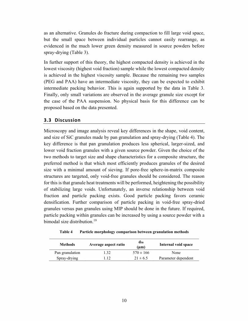
3.3 Discussion
Microscopy and image analysis reveal key differences in the shape, void content, and size of SiC granules made by pan granulation and spray-drying (Table 4). The key difference is that pan granulation produces less spherical, larger-sized, and lower void fraction granules with a given source powder. Given the choice of the two methods to target size and shape characteristics for a composite structure, the preferred method is that which most efficiently produces granules of the desired size with a minimal amount of sieving. If pore-free sphere-in-matrix composite structures are targeted, only void-free granules should be considered. The reason for this is that granule heat treatments will be performed, heightening the possibility of stabilizing large voids. Unfortunately, an inverse relationship between void fraction and particle packing exists. Good particle packing favors ceramic densification. Further comparison of particle packing in void-free spray-dried granules versus pan granules using MIP should be done in the future. If required, particle packing within granules can be increased by using a source powder with a bimodal size distribution.19
Table 4 Particle morphology comparison between granulation methods
Methods Average aspect ratio d50
(µm) Internal void space
Pan granulation 1.32 570 ± 166 None Spray-drying 1.12 21 ± 6.5 Parameter dependent

11
4. Powder Processing and Densification
The first ceramic composite processing experiments were conducted using pan-granulated powders. Mixtures of 20 wt% granules with 80 wt% fine B4C powders (HC Starck HS grade) with published d50 of 0.8 µm were massed and combined in an acoustic mixer (Resodyn Labram) and loaded into 1-inch-diameter graphite dies for hot-pressing. Hot-pressing was carried out at 1950 °C for 2 h under 40-MPa load in a flowing argon atmosphere and in a tungsten heating element furnace (Oxy-Gon Industries). This sample is measured by the Archimedes method to be 99% of the theoretical density. Figure 7a shows a polished cross section of a hot-pressed sample. Large phase regions (>50 µm) of both SiC (light color) and B4C (dark color) are visible in the backscattered SEM micrograph. In addition, regions with grain-scale (1–5 µm) mixing of SiC with B4C are also visible. The large regions of B4C suggest that the fine powders form soft agglomerates in the mixer. The intermixed regions suggest either that a large fraction of fines is present or that the particles break apart during mixing. Finally, some SiC regions show a very large aspect ratio, with the long axis perpendicular to the direction of applied load. This suggests that granules deform during hot-pressing.
Fig. 7 Example micrographs of B4C matrix ceramics with SiC granules incorporated as a reinforcing phase by a) dry mixing and b) prefiring and aqueous mixing
A second ceramic processing trial used pan granules that were posttreated at 1700 °C for 4 h before mixing. To combat the formation of soft agglomerates in the fine B4C powder, a 20–80 mixture by weight was dispersed in water using ammonium polyacrylate (Darvan 821-A). The mixture was stirred using a drill mixer and dried using a rotary evaporator (Heidolph instruments) set at 42 °C and 70 mbar. The powder was then dried overnight in a vacuum oven set at 80 °C. A

12
5-g powder sample was loaded into a 1-inch-diameter graphite die for a second hot-pressing experiment at 1950 °C for 2 h under 40 MPa load in a flowing argon. This sample is also measured by the Archimedes method to be 99% of the theoretical density. Figure 7b shows a polished cross section. No large regions of B4C agglomerates are visible. The SiC granules are still deformed, but not to the same extreme as the first sample. The fact that the B4C region is still speckled with SiC suggests that a large number of SiC fines are present. Some amount of SiC fines mixed into the B4C matrix is helpful in achieving full density; however, the number of fines may be controlled in the future by sieving. Finally, the SiC granules are dispersed much better in the B4C matrix than in the first processing trial.
5. Conclusion
The methods of pan granulation and spray-drying have been used to demonstrate some degree of control over size, shape, and void fraction in the reinforcing phase of a ceramic–ceramic composite. In the case of spray-drying, suspension viscosity has been tied to the granule void content and packing fraction by both experimental observations and previously described droplet drying theory. Efficient production of granules in a large range of sizes between 10 µm and 1 mm can be achieved with spray-drying (small sizes) and pan granulation (large sizes). To demonstrate the production of a ceramic composite with secondary phase of tunable size, initial mixing and hot-pressing experiments were carried out. The most effective way to create an idealized matrix of B4C containing a well-dispersed spherical SiC reinforcing phase was by prefiring SiC granules followed by a multistep aqueous mixing process. These methods will be used in future studies of the effect of microstructure, especially the size and distribution of reinforcing phases, on the mechanical properties of ceramic–ceramic armor composites.

13
6. References
1. Neuman EW, Brown-Shaklee HJ, Hilmas GE, Fahrenholtz WG. Titanium diboride-silicon carbide-boron carbide ceramics with super-high hardness and strength. J Am Ceram Soc. 2018;101(2):497–501.
2. Stadelmann R, Lugovy M, Orlovskaya N, McHaffey P, Radovic M, Sglavo VM, Grasso S, Reece MJ. Mechanical properties and residual stresses in ZrB2–SiC spark plasma sintered ceramic composites. J Eur Ceram Soc. 2016;36(7):1527–1537.
3. Miller JA, Reimanis IE, Du Merac MR. Enhanced fracture toughness in nonstoichiometric magnesium aluminate spinel through controlled dissolution of second phase alumina. J Am Ceram Soc. 2018;101(2):812–820.
4. Harris DC, et al. Properties of an infrared-transparent MgO:Y2O3 nanocomposite. J Am Ceram Soc. 2013;96(12):3828–3835.
5. Wahl J, Gentilman R, Tustison R, Nordahl C, Nguyen H, Korenstein R, inventors; Raytheon Company, assignee. Long wave infrared transparent window and coating materials. United States patent US 10385220 . 2019 Aug 20.
6. Banik SR, Iqbal IM, Nath R, Bora LJ, Singh BK, Mandal N, Sankar MR. State of the art on zirconia toughened alumina cutting tools. Mater Today. 2019;18:2632–2641.
7. Yasar ZA, Haber RA, Rafaniello W. SPS sintered silicon carbide-boron carbide composites. In: Advances in ceramic armor, bioceramics, and porous materials. New York (NY): John Wiley & Sons, Inc; 2017. p. 13–20.
8. Williams T. Development of pressureless sintered silicon carbide-boron carbide composites for armour applications [thesis]. [Guildford (England)]: University of Surrey; 2015.
9. Sigl LS, Kleebe H-J. Microcracking in B4C-TiB2 composites. J Am Ceram Soc. 1995;78(9):237–2380.
10. Green DJ, Chou Y-S. Silicon carbide platelet/alumina composites: III toughening mechanisms. J Am Ceram Soc. 1993;76(8):1985–1992.
11. Faber KT, Evans AG. Crack deflection processes—I theory. Acta Metallurgica. 1983;31(4):565–576.

14
12. Tasdemirci A, Tunusoglu G, Güden M. The effect of the interlayer on the ballistic performance of ceramic/composite armors: experimental and numerical study. Int J Impact Eng. 2012;44:1–9.
13. Arpagaus C, Collenberg A, Rütti D. Laboratory spray drying of materials for batteries, lasers, and bioceramics. Drying Technol. 2019;37(4):426–434.
14. Melchiades F, Santos LR, Nastri S, Boschi A. Comparison between spray-dried and dry granulated powders in the fabrication of porcelain tiles. InterCeram: International Ceramic Review. 2012;61:254–258.
15. WJ Walker Jr, Reed JS, Verma SK. Influence of slurry parameters on the characteristics of spray-dried granules. J Am Ceram Soc. 1999;82(7):1711–1719.
16. Frey RG, Halloran JW. Compaction behavior of spray-dried alumina. J Am Ceram Soc. 1984;67(3):199–203.
17. Walton DE. Spray-dried particle morphologies. Developments in Chemical Engineering and Mineral Processing. 2002;10:323–348.
18. Shoulders WT, Bizarri G, Bourret E, Gaume RM. Influence of process parameters on the morphology of spray-dried BaCl2 powders. J Am Ceram Soc. 2016;99(1):20–26.
19. Pfeiffer S, Florio K, Makowska M, Ferreira Sanchez D, Van Swygenhoven H, Aneziris CG, Wegener K, Graule T. Iron oxide doped spray dried aluminum oxide granules for selective laser sintering and melting of ceramic parts. Adv Eng Mater. 2019(1801351).
15
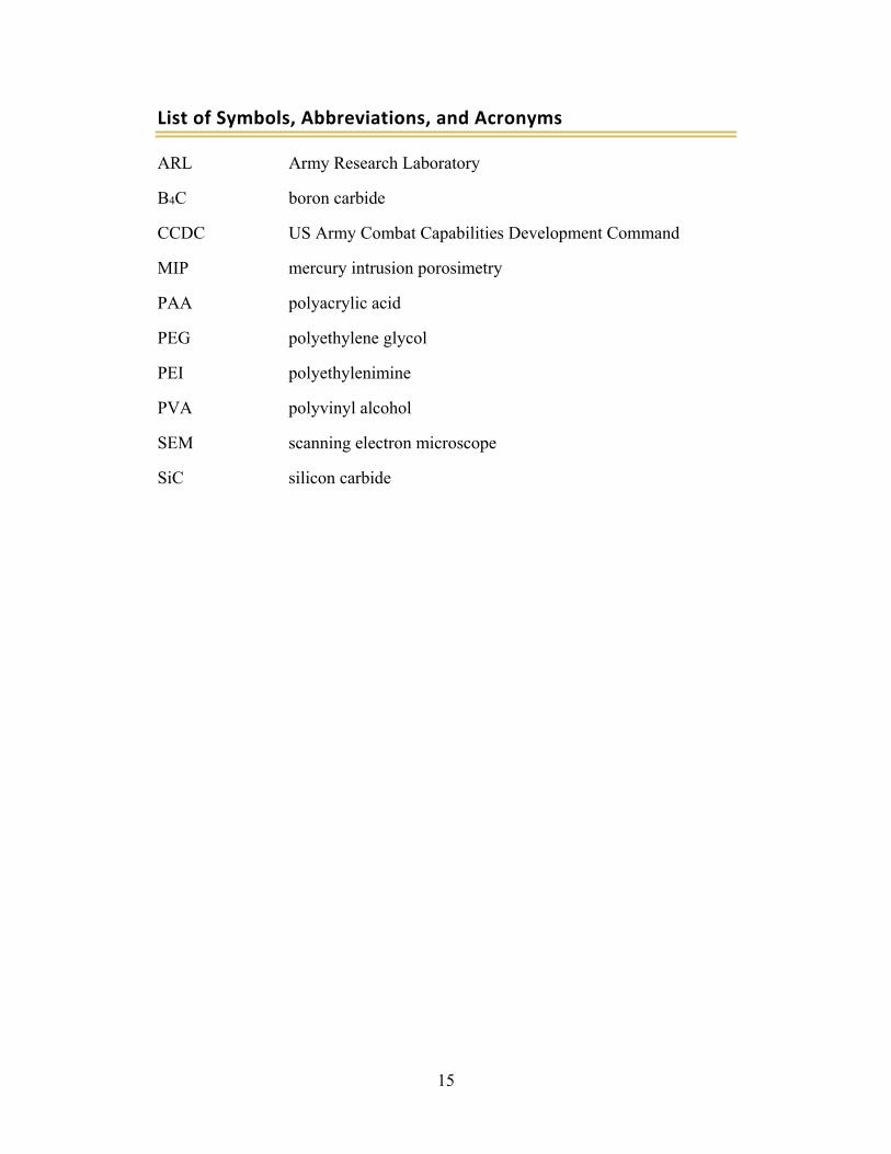
List of Symbols, Abbreviations, and Acronyms
ARL Army Research Laboratory
B4C boron carbide
CCDC US Army Combat Capabilities Development Command
MIP mercury intrusion porosimetry
PAA polyacrylic acid
PEG polyethylene glycol
PEI polyethylenimine
PVA polyvinyl alcohol
SEM scanning electron microscope
SiC silicon carbide

16
1 DEFENSE TECHNICAL (PDF) INFORMATION CTR DTIC OCA 1 CCDC ARL (PDF) FCDD RLD CL TECH LIB 1 CCDC ARL (PDF) FCDD RLW ME W T SHOULDERS