Embed Size (px)
Citation preview

TFX SERIES GRAIN AUGERS831, 836, 841, 846, 851, 1031, 1036, & 1041 MODELSASSEMBLY & OPERATION MANUAL
Part Number: 30666 R3
Revised:2/4/14
Read this manual before using product. Failure to follow instructions and safety precautions can result in serious injury, death, or property damage. Keep manual for future reference.

This product has been designed and constructed according to general engineering standardsa. Other local regulations may apply and must be followed by the operator. We strongly recommend that all personnel associated with this equipment be trained in the correct operational and safety procedures required for this product. Periodic reviews of this manual with all employees should be standard practice. For your convenience, we include this sign-off sheet so you can record your periodic reviews.
a. Standards include organizations such as the American Society of Agricultural and Biological Engineers, American National Standards Institute, Canadian Standards Association, International Organization for Standardization, EN Standards, and/or others.
Date Employee Signature Employer Signature

TABLE OF CONTENTS
WESTFIELD - TFX SERIES GRAIN AUGERS 831, 836, 841, 846, 851, 1031, 1036, & 1041 MODELS
1. Introduction .......................................................................................................................... 5
2. Safety .................................................................................................................................... 72.1. General Safety Information ...................................................................................... 72.2. Assembly Safety....................................................................................................... 82.3. Transport & Placement Safety ................................................................................ 92.4. Operation Safety .................................................................................................... 102.5. PTO Safety............................................................................................................. 122.6. Gas Engine Safety ................................................................................................. 122.7. Electric Motor Safety .............................................................................................. 122.8. Hydraulic Safety ..................................................................................................... 122.9. Battery Safety......................................................................................................... 132.10. Maintenance Safety.............................................................................................. 132.11. Safety Decal Locations......................................................................................... 14
2.11.1. Decal Installation .................................................................................... 142.11.2. Decal Locations ...................................................................................... 14
3. Assembly ............................................................................................................................ 193.1. Tubes & Flighting ................................................................................................... 19
3.1.1. Decal Installation Instructions................................................................... 203.2. Track Shoe & Trackstop......................................................................................... 213.3. Intake Hitch ............................................................................................................ 223.4. Driveshaft ............................................................................................................... 223.5. Gearbox.................................................................................................................. 233.6. Driveshaft Guard .................................................................................................... 243.7. Truss ...................................................................................................................... 253.8. Transport Undercarriage ........................................................................................ 263.9. Winch & Lift Cable.................................................................................................. 303.10. Winch Handle ....................................................................................................... 313.11. Winch Cable Routing............................................................................................ 323.12. Gas / Electric Motor Mount Installation................................................................. 343.13. PTO Drive Installation (Optional).......................................................................... 413.14. Battery Mount (Optional) ...................................................................................... 463.15. Gas Tank Mount................................................................................................... 473.16. Upper Housing Lubrication................................................................................... 473.17. Plastic Manual Holder .......................................................................................... 47
4. Transport & Placement ...................................................................................................... 494.1. Transport Procedure .............................................................................................. 494.2. Placement Procedure............................................................................................. 50
30666 R3 3

TABLE OF CONTENTS
WESTFIELD - TFX SERIES GRAIN AUGERS
831, 836, 841, 846, 851, 1031, 1036, & 1041 MODELS
5. Operation ............................................................................................................................ 535.1. Pre-Operational Checklist....................................................................................... 535.2. Auger Drive & Lockout Procedure .......................................................................... 535.3. Operating Procedure .............................................................................................. 54
5.3.1. Start-Up & Break-In .................................................................................. 545.3.2. Operating With A Full Load....................................................................... 555.3.3. Shutdown.................................................................................................. 565.3.4. Lowering & Completion............................................................................. 56
5.4. Horsepower Requirements..................................................................................... 57
6. Maintenance & Storage...................................................................................................... 596.1. General Maintenance Procedures.......................................................................... 596.2. General Storage Procedures.................................................................................. 61
7. Troubleshooting ................................................................................................................. 63
Warranty.................................................................................................................................. 65
4 30666 R3

WESTFIELD - TFX SERIES GRAIN AUGERS 1. INTRODUCTION
831, 836, 841, 846, 851, 1031, 1036, & 1041 MODELS
1. IntroductionThank you for purchasing a Westfield grain auger. Before using, please read this manual and understand the various features of the equipment and precautions for efficient and safe operation.
Keep this manual handy for frequent reference and to review with new personnel. A sign-off form is supplied on the inside front cover to record your safety reviews. Call your local distributor or dealer if you need assistance or additional information.
This manual should be regarded as part of the equipment. Suppliers of both new and second-hand equipment are advised to retain documentary evidence that this manual was provided with the machine.
Serial Number:
Serial number is on the right, at the top of the lower tube.
30666 R3 5

1. INTRODUCTION WESTFIELD - TFX SERIES GRAIN AUGERS
831, 836, 841, 846, 851, 1031, 1036, & 1041 MODELS
6 30666 R3

WESTFIELD - TFX SERIES GRAIN AUGERS 2. SAFETY
831, 836, 841, 846, 851, 1031, 1036, & 1041 MODELS 2.1. GENERAL SAFETY INFORMATION
2. Safety2.1. GENERAL SAFETY INFORMATION
The Safety Alert symbol identifies important safety messages on the product and in the manual. When you see this symbol, be alert to the possibility of personal injury or death. Follow the instructions in the safety messages.
Why is SAFETY important?
• Accidents disable and kill.• Accidents cost.• Accidents can be avoided.
SIGNAL WORDS: Note the use of the signal words DANGER, WARNING, CAUTION, and NOTICE with the safety messages. The appropriate signal word for each message has been selected using the definitions below as a guideline.
DANGER
Indicates an imminently hazardous situation that, if not avoided, will result in serious injury or death.
WARNING
Indicates a hazardous situation that, if not avoided, could result in serious injury or death.
CAUTION
Indicates a hazardous situation that, if not avoided, may result in minor or moderate injury.
NOTICE
Indicates a potentially hazardous situation that, if not avoided, may result in property damage.
30666 R3 7

2. SAFETY WESTFIELD - TFX SERIES GRAIN AUGERS
2.2. ASSEMBLY SAFETY 831, 836, 841, 846, 851, 1031, 1036, & 1041 MODELS
YOU are responsible for the SAFE use and maintenance of your equipment. YOU must ensure that you and anyone else who is going to work around the equipment understands all procedures and related SAFETY information contained in this manual.
Remember, YOU are the key to safety. Good safety practices not only protect you, but also the people around you. Make these practices a working part of your safety program.
Important: Below are general instructions that apply to all safety practices. Any instructions specific to a certain safety practice (e.g., Operational Safety), can be found in the appropriate section. Always read the complete instructional sections and not just these safety summaries before doing anything with the equipment.
• It is the equipment owner, operator, and maintenance personnel's responsi-bility to read and understand ALL safety instructions, safety decals, and man-uals and follow them when assembling, operating, or maintaining the equipment. All accidents can be avoided.
• Equipment owners must give instructions and review the information initially and annually with all personnel before allowing them to operate this product. Untrained users/operators expose themselves and bystanders to possible serious injury or death.
• Use this equipment for its intended purposes only.• Do not modify the equipment in any way without written permission from the
manufacturer. Unauthorized modification may impair the function and/or safety, and could affect the life of the equipment. Any unauthorized modifica-tion of the equipment voids the warranty.
• Do not allow any unauthorized person in the work area.
2.2. ASSEMBLY SAFETY
• Read and understand the instructions to get to know the sub-assemblies and hardware that make up the equipment before preceding to assemble the product.
• Do not take chances with safety. The components are large, heavy, and can be hard to handle. Always use the proper tools, stands, jacks, and hoists for the job.
• Read and understand assembly instructions before proceeding to assemble the product.
• Always have two or more people assembling the equipment. Because of the weight, do not attempt assembly alone.
8 30666 R3

WESTFIELD - TFX SERIES GRAIN AUGERS 2. SAFETY
831, 836, 841, 846, 851, 1031, 1036, & 1041 MODELS 2.3. TRANSPORT & PLACEMENT SAFETY
2.3. TRANSPORT & PLACEMENT SAFETY
• Transport auger in full down position with slight tension on cable.
• Properly place hitch pin and securely attach safety chain. Use a type of hitch pin that will not allow auger to separate from towing vehi-cle.
• Always attach an SMV (slow moving vehicle) sign before transporting auger. Equip the auger with the necessary lights for transpor-tation where required by law. Always use hazard warning flashers on the tractor/towing vehicle when transporting unless prohibited by law.
• Always travel at a safe speed, never exceed-ing 15 mph (24 km/hr). Reduce speed on rough surfaces and be cautious when turning corners or meeting traffic.
• Before raising/lowering/moving the auger, make sure the area around the auger is clear of obstructions and/or untrained personnel. Never allow anyone to stand on or beneath auger while transporting or placing auger.
• Do not transport auger on slopes greater than 20°.
• Wheels must be free to move when raising or lowering auger.
• Never attempt to move auger manually. To do so will result in serious injury.
• Before moving auger, check for overhead obstructions and/or electrical wires. Electrocution can occur without direct contact.
• PTO models only: Disconnect PTO driveline from tractor before moving auger or tractor and secure in transport saddle (where applicable).
• If the track shoe becomes stuck when lowering the auger, continuing to turn the winch handle counter-clockwise will disengage the brake mechanism and create an unsafe condition. Too much slack in the cable may also cause the auger to drop suddenly.
• The winch must make a clicking sound when raising auger. If clicking sound stops, retain grip on handle, lower auger fully, and repair winch.
• After lowering auger, turn handle clockwise two clicks to lock winch brake.• Always keep a minimum of 3 cable wraps on the winch drum.• The winch is designed for manual operation only.
ELECTROCUTION HAZARD
30666 R3 9

2. SAFETY WESTFIELD - TFX SERIES GRAIN AUGERS
2.4. OPERATION SAFETY 831, 836, 841, 846, 851, 1031, 1036, & 1041 MODELS
2.4. OPERATION SAFETY
• Have another trained person nearby who can shut down the auger in case of accident. Always work with a second trained person around augers.
• Do not operate with any of the safety guards removed.• Keep body, hair, and clothing away from moving parts. Stay away from intake
during operation.• Inspect lift cable before using auger. Replace if frayed or damaged. Make
sure it is seated properly in cable sheaves and cable clamps are secure.• Operate auger on level ground free of debris. If ground is uneven, anchor the
auger to prevent tipping or upending.• Augers are not insulated. Keep away from electrical lines. Electrocution can
occur without direct contact.• Support the discharge end and/or anchor the intake end before operating to
prevent upending.• Do not use auger as a hoist.• Empty auger before raising or lowering.• Lower auger at completion of operation or when not in use. Auger could drop
rapidly in case of cable break or hydraulic failure (where applicable).• Keep the work area clean and tidy.
• Inspect the drive belt(s) before using auger. Replace if frayed or damaged.• Lock winch before operating auger.• Do not grab or touch drive belt(s) during operation for any reason.
10 30666 R3

WESTFIELD - TFX SERIES GRAIN AUGERS 2. SAFETY
831, 836, 841, 846, 851, 1031, 1036, & 1041 MODELS 2.4. OPERATION SAFETY
Figure 2.1 Auger Hazard Areas
30666 R3 11

2. SAFETY WESTFIELD - TFX SERIES GRAIN AUGERS
2.5. PTO SAFETY 831, 836, 841, 846, 851, 1031, 1036, & 1041 MODELS
2.5. PTO SAFETY
• Never use a PTO driveline without a rotating shield in good working order.• Ensure PTO driveline is securely attached at both ends before operating.• Before starting tractor, turn power to PTO to the off position (where applica-
ble).• Keep body, hair, and clothing away from rotating PTO driveline.• Ensure the PTO driveline shields turn freely on the PTO driveline.• Do not exceed operating speed of 540 rpm.• Keep u-joint angles small and equal. Do not exceed recommended operating
length for PTO driveline.
2.6. GAS ENGINE SAFETY
• Read and understand the operating and maintenance instructions that came with the gas engine.
• Inspect the drive belts before using auger. Replace if frayed or damaged.• Do not grab or touch drive belts during operation for any reason.• Keep the shields on.
2.7. ELECTRIC MOTOR SAFETY
• Inspect the drive belts before using auger. Replace if frayed or damaged.• Do not grab or touch drive belts during operation for any reason.• Remember to ground electric motor before using auger.
• Keep the shields on.
2.8. HYDRAULIC SAFETY
• Always place all hydraulic controls in neutral and relieve system pressure before disconnecting or working on hydraulic system.
• Keep all components in the hydraulic system tightly secured, clean and in good condition.
• Replace any worn, cut, abraded, flattened, or crimped hoses.• Do not attempt any makeshift repairs to the hydraulic fittings or hoses with
tape, clamps, or adhesive. The hydraulic system operates under extremely high pressure; such repairs will fail suddenly and create a hazardous and unsafe condition.
12 30666 R3

WESTFIELD - TFX SERIES GRAIN AUGERS 2. SAFETY
831, 836, 841, 846, 851, 1031, 1036, & 1041 MODELS 2.9. BATTERY SAFETY
• Before moving a hydraulic cylinder, ensure that the attached component is safely secured.
2.9. BATTERY SAFETY
• Wear safety glasses when working near batteries.• Make certain the battery or terminal covers are in place and in good working
order.• Keep all sparks and flames away from batteries; gas given off by electrolyte is
explosive.• Avoid contact with battery electrolyte. Wash off any spilled electrolyte immedi-
ately.• Do not tip batteries more than 45° to avoid electrolyte loss.• To avoid injury from sparks or short circuits, disconnect battery ground cable
before servicing any part of an electrical system.
2.10. MAINTENANCE SAFETY
• Shut down and lock out all power before attempting maintenance of any kind. If applicable, disconnect PTO driveline from tractor.
• After maintenance is complete, replace and secure all safety guards and safety devices, and if applicable, service doors and cleanout covers.
• Support auger tube before attempting maintenance on the undercarriage assembly. Auger should be in full down position for maintenance.
• Use only genuine Westfield replacement parts or equivalent. Replacement parts such as intake guards, pulley guards, PTO driveline shields, winches, and lift cables must meet ASABE standards or serious injury may result. Use of unauthorized parts will void warranty. If in doubt, contact Westfield or your Westfield dealer.
• Do not modify any auger components without authorization from Westfield. Modification can be dangerous and result in serious injuries.
WARNING
Hydraulic fluid can cause serious injury if it penetrates the skin. If it does, see a doctor immediately.• Relieve pressure before disconnecting
hydraulic line.• Wear proper hand and eye protection and
use wood or cardboard, not hands, when searching for leaks.
30666 R3 13
2. SAFETY WESTFIELD - TFX SERIES GRAIN AUGERS
2.11. SAFETY DECAL LOCATIONS 831, 836, 841, 846, 851, 1031, 1036, & 1041 MODELS
2.11. SAFETY DECAL LOCATIONS
• Keep safety decals clean and legible at all times.• Replace safety decals that are missing or have become illegible. See decal
location figures that follow.• Replaced parts must display the same decal(s) as the original part.• Safety decals are available from your distributor, dealer, or factory.
2.11.1. DECAL INSTALLATION
1. Decal area must be clean and dry, with a temperature above 50°F (10°C).2. Decide on the exact position before you remove the backing paper.3. Align the decal over the specified area and carefully press the small portion
with the exposed sticky backing in place.4. Slowly peel back the remaining paper and carefully smooth the remaining
portion of the decal in place.5. Small air pockets can be pierced with a pin and smoothed out using the sign
backing paper.
2.11.2. DECAL LOCATIONS
Replicas of the safety decals that are attached to the equipment are shown in this section. Good safety requires that you familiarize yourself with the various safety decals and the areas or particular functions that the decals apply to as well as the safety precautions that must be taken to avoid serious, injury, death, or damage.
* Westfield reserves the right to update safety decals without notice. Safety decals may not be exactly as shown.
14 30666 R3
WESTFIELD - TFX SERIES GRAIN AUGERS 2. SAFETY
831, 836, 841, 846, 851, 1031, 1036, & 1041 MODELS 2.11. SAFETY DECAL LOCATIONS
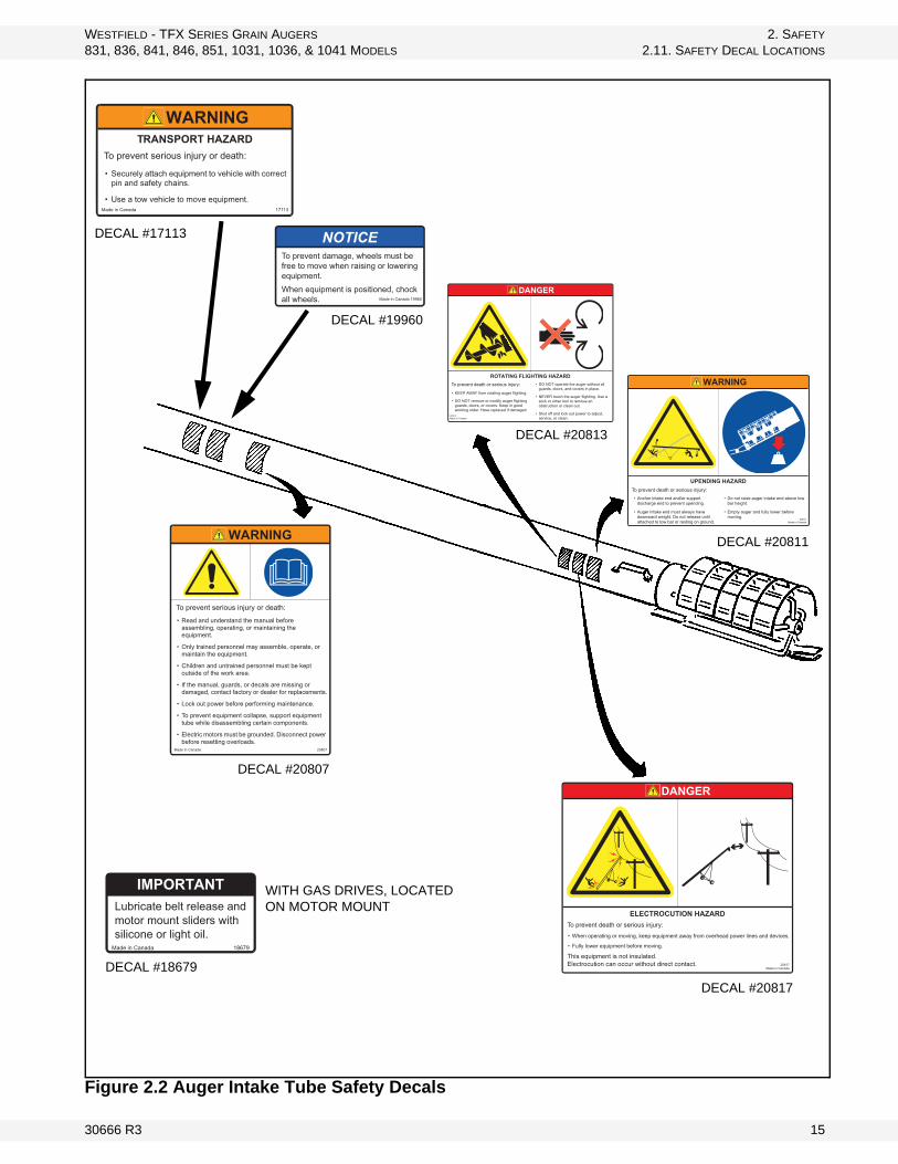
Figure 2.2 Auger Intake Tube Safety Decals
WARNING
To prevent serious injury or death:
• Read and understand the manual before assembling, operating, or maintaining the equipment.
• Only trained personnel may assemble, operate, or maintain the equipment.
• Children and untrained personnel must be kept outside of the work area.
• If the manual, guards, or decals are missing or damaged, contact factory or dealer for replacements.
• Lock out power before performing maintenance.
• To prevent equipment collapse, support equipment tube while disassembling certain components.
• Electric motors must be grounded. Disconnect power before resetting overloads.
Made in Canada 20807
DANGER
ELECTROCUTION HAZARDTo prevent death or serious injury:
• When operating or moving, keep equipment away from overhead power lines and devices.
• Fully lower equipment before moving.
This equipment is not insulated.Electrocution can occur without direct contact. 20817
Made in Canada
IMPORTANTLubricate belt release and motor mount sliders with silicone or light oil.
97681adanaC ni edaM
DANGER
ROTATING FLIGHTING HAZARDTo prevent death or serious injury:
• KEEP AWAY from rotating auger flighting.
• DO NOT remove or modify auger flighting guards, doors, or covers. Keep in good working order. Have replaced if damaged.
• DO NOT operate the auger without all guards, doors, and covers in place.
• NEVER touch the auger flighting. Use a stick or other tool to remove an obstruction or clean out.
• Shut off and lock out power to adjust, service, or clean.
20813Made in Canada
NOTICETo prevent damage, wheels must be free to move when raising or lowering equipment.When equipment is positioned, chock all wheels. Made in Canada 19960
WITH GAS DRIVES, LOCATED ON MOTOR MOUNT
DECAL #18679
DECAL #20807
DECAL #20817
DECAL #20811
DECAL #20813
DECAL #17113
DECAL #19960
WARNINGTRANSPORT HAZARD
To prevent serious injury or death:
• Securely attach equipment to vehicle with correct pin and safety chains.
• Use a tow vehicle to move equipment.31171adanaC ni edaM
WARNING
UPENDING HAZARDTo prevent death or serious injury:• Anchor intake end and/or support
discharge end to prevent upending.
• Auger intake end must always have downward weight. Do not release until attached to tow bar or resting on ground.
• Do not raise auger intake end above tow bar height.
• Empty auger and fully lower before moving.
20811Made in Canada
30666 R3 15

2. SAFETY WESTFIELD - TFX SERIES GRAIN AUGERS
2.11. SAFETY DECAL LOCATIONS 831, 836, 841, 846, 851, 1031, 1036, & 1041 MODELS
Figure 2.3 V-Belt Guard and PTO Shield Safety Decals
PLACED ON MACHINE BEHIND GUARD
DECAL #20803
DECAL #20804
DECAL #20818
ONLY ON PTO MODELS
DECAL #20803
DANGERROTATING PTO DRIVELINE HAZARD
To prevent serious injury or death:• Keep body, hair, and clothing away from rotating PTO driveline.• Do not operate equipment unless all driveline, tractor, and
equipment shields are in place and in good working order.• Make certain the driveline shields turn freely on driveline.• Make certain the driveline is securely attached at both ends.• Do not exceed operating speed of 540 rpm.• Keep u-joint angles small and equal. Do not exceed maximum
recommended length for PTO driveline.Made in Canada 20818
WARNINGMISSING GUARD HAZARDTo prevent serious injury or death, shut off power and reattach guard before operating machine.
20803Made in Canada
WARNINGMISSING GUARD HAZARDTo prevent serious injury or death, shut off power and reattach guard before operating machine.
20803Made in Canada
WARNING
ENTANGLEMENT HAZARDTo prevent serious injury or death:
• Keep body, hair, and clothing away from rotating pulleys, belts, chains, and sprockets.
• Do not operate with any guard removed or modified. Keep guards in good working order.
• Shut off and remove key or lock out power before source before inspecting or servicing machine.
Made in Canada 20804
16 30666 R3

WESTFIELD - TFX SERIES GRAIN AUGERS 2. SAFETY
831, 836, 841, 846, 851, 1031, 1036, & 1041 MODELS 2.11. SAFETY DECAL LOCATIONS
Figure 2.4 Winch Safety Decal
CAUTIONFor proper raising and lowering of equipment:
• Tighten brake lock by turning winch handle clockwise at least two clicks after lowering equipment.
• Lower equipment fully before towing, then rotate winch handle until cable has light tension.
• Do not lubricate winch brake discs.
• Inspect lift cable periodically; replace if damaged.
• Inspect cable clamps periodically; tighten if necessary. 17109
Made in Canada
DECAL #17109
30666 R3 17
2. SAFETY WESTFIELD - TFX SERIES GRAIN AUGERS
2.11. SAFETY DECAL LOCATIONS 831, 836, 841, 846, 851, 1031, 1036, & 1041 MODELS
18 30666 R3

WESTFIELD - TFX SERIES GRAIN AUGERS 3. ASSEMBLY
831, 836, 841, 846, 851, 1031, 1036, & 1041 MODELS 3.1. TUBES & FLIGHTING
3. Assembly
Before beginning assembly, familiarize yourself with all the sub-assemblies and hardware making up the auger. Have all parts on hand and arrange them for easy access. Carry out assembly in a large open area with a level surface.
Important: Always have 2 or more people assembling the equipment. Because of the weight, do not attempt assembly alone.
Augers are available in various combinations. In most cases, the following instructions will apply to all augers. Where the assembly information varies, additional instructions will be included and will be indicated with an arrow.
Some components of the auger are to be installed on one side of the auger only. These directions are always given facing the discharge end of the auger as shown in Figure 3.1.
Figure 3.1
3.1. TUBES & FLIGHTING 1. Position tube sections. Align tube sections on a flat surface or on a series of
benches.
WARNING Before continuing, ensure you have read and understand the relevant information in the safety section. Safety information is provided to help prevent serious injury, death, or property damage.
30666 R3 19

3. ASSEMBLY WESTFIELD - TFX SERIES GRAIN AUGERS
3.1. TUBES & FLIGHTING 831, 836, 841, 846, 851, 1031, 1036, & 1041 MODELS
2. Slide lower flight shaft into upper flight shaft until flight ends butt together and flighting spiral matches up (see Figure 3.2). Secure with hardware listed in Table 3.1 below.
3. Slide tube sections together and secure. Make sure to align upper and lower track ends and then tighten bolts. Secure with hardware listed in Table 3.1 below.
Flight shaft connections, as well as flight connection bolts should slide into place easily. Do not force into place.
Track ends must align to allow track shoe to smoothly slide over track joint. Misalignment may cause jamming.
3.1.1. DECAL INSTALLATION INSTRUCTIONS
Figure 3.3
Important: Do not cover any existing safety or instruction decals with the model decal.
WARNING
Do not drop. Damage to equipment or serious personal injury will result.
Figure 3.2 Flighting Joint Bolting
Note:
Important:
Table 3.1 Flighting and Tube FastenersAuger For Flighting Qty. For Tubes Qty.
8” 7/16” x 2-1/4” GR 8 bolts and locknuts 2 7/16” x 1” bolts and locknuts 810” 1/2” x 2-3/4” GR 8 bolts and locknuts 2 7/16” x 1” bolts and locknuts 8
20 30666 R3

WESTFIELD - TFX SERIES GRAIN AUGERS 3. ASSEMBLY
831, 836, 841, 846, 851, 1031, 1036, & 1041 MODELS 3.2. TRACK SHOE & TRACKSTOP
For most decal applications, follow the diagrams as seen in Figure 3.3 Apply decals to both sides of auger tube.
Lower Tubes: Decals should be located just below the angle flange, centered on the tube. Decals should be easily visible from the ground when auger assembly is complete.
(For 36' augers, the model decal can be located in the center of the lower tube)
Upper Tubes: "Westfield" decals should be placed in the center of the upper tube, where they are easily visible from the ground when auger assembly is complete.
3.2. TRACK SHOE & TRACKSTOP
1. The 51' auger has a 2-piece lift track. Make sure the upper and lower tube track sections butt together to form a smooth joint for the roller track shoe to roll across. Adjust if necessary (Figure 3.4).
2. All augers: slide roller trackshoe onto track. Attach the upper angle-iron trackstop with 7/16” x 1-1/4" bolts, heavy flat washers, and locknuts (Figure 3.5). Ensure trackstop is installed in correct position by referring to Table 3.2.
3. Attach the lower angle-iron trackstop with 7/16” x 1-1/4” bolts and locknuts as shown in Figure 3.6. Ensure trackstop is installed in correct position by referring to Table 3.2. Tighten securely.
Figure 3.4 51’ Lift Track Only
Figure 3.5
Figure 3.6 Lower Track Stop
30666 R3 21

3. ASSEMBLY WESTFIELD - TFX SERIES GRAIN AUGERS
3.3. INTAKE HITCH 831, 836, 841, 846, 851, 1031, 1036, & 1041 MODELS
3.3. INTAKE HITCH
1. Clean dirt and paint from lower flight stub and intake bushing.
2. Attach intake hitch to lower auger tube and tighten securely.
3. Maintain 1/4” (0.64 cm) clearance between bushing and end of flight.
4. Attach clevis to intake hitch with clevis pin and gripclip.
3.4. DRIVESHAFT
Upper sections of the driveshaft are factory installed. To install the lower section follow the steps below.
1. Check Table 3.3 below for correct sequence for your auger.2. Clean dirt from driveshaft end and shaft connectors.3. After installing Woodruff key, slide connector halfway onto the last pre-
installed driveshaft segment.
Table 3.2 Auger Upper Track Stop Lower Track Stop
831 only set of holes at top of track 2nd set of holes from bottom of track836 only set of holes at top of track 1st set of holes from bottom of track841 2nd set of holes from top of track 2nd set of holes from bottom of track846 2nd set of holes from top of track 1st set of holes from bottom of track
851 3rd set of holes from top of trackonly set of holes on short piece of track on
lower tube1031 only set of holes at top of track 2nd set of holes from bottom of track1036 only set of holes at top of track 1st set of holes from bottom of track1041 2nd set of holes from top of track 2nd set of holes from bottom of track
CAUTION
Failure to locate trackstops in the proper holes can result in damage to auger and/or personal injury.
Figure 3.7 Hitch
Part Size Amount
Intake Hitch 7/16” x 1-1/4” bolt and locknut 6
Clevis Pin 5/8” 1
22 30666 R3

WESTFIELD - TFX SERIES GRAIN AUGERS 3. ASSEMBLY
831, 836, 841, 846, 851, 1031, 1036, & 1041 MODELS 3.5. GEARBOX
4. Slip lower driveshaft segments through bearings on lower tube section, install a Woodruff key, and slide into shaft connector.
5. Tighten all set screws on shaft connectors.6. Place a few drops of oil at each driveshaft bearing for break-in. These
bearings will not require further lubrication because they are self-lubricating.
3.5. GEARBOX
The gearbox is supplied from the factory mounted to the gearbox plate with chain coupler in place. The PTO drive mount is mounted on the left side of the auger.
If the PTO drive mount must be accessible from the right side of the auger, the gearbox will have to be flipped and mounted opposite so that the input shaft of the gearbox is on the right side. Refer to Figure 3.1 for left-right orientation.
• 31’ auger (all diameters): Mount gearbox on the gearbox mounting bracket closest to the discharge end of the auger.
• 36’ auger: Mount gearbox to the bracket closest to the intake end.• All other auger sizes have one mounting bracket.
To install:1. Remove chain and
secure half the coupler to the driveshaft with a Woodruff key.
2. Place gearbox assembly onto the mounting bracket welded to tube, then reinstall chain, leaving 1/16” clearance between chain coupler sprockets. Secure gearbox assembly with four 7/16” x 1-1/4" bolts and locknuts as shown in Figure 3.8.
Table 3.3
AUGER MODEL LOWER DRIVESHAFT LENGTH DIAMETER
831 / 1031 N/A N/A836 2’ - 7” 1-1/4”1036 2’ - 10” 1-1/4”841 3’ - 11-1/2” 1-1/4”1041 4’ - 7-3/4”” 1-1/4”846 6’ - 11-1/4” 1-1/4”851 9’ - 9-3/4” 1-1/4”
Figure 3.8
30666 R3 23

3. ASSEMBLY WESTFIELD - TFX SERIES GRAIN AUGERS
3.6. DRIVESHAFT GUARD 831, 836, 841, 846, 851, 1031, 1036, & 1041 MODELS
Note: Gearbox is sent from the factory half full of EP90 lube oil. Make sure gearbox is half full before operating auger. Add EP90 lube oil if necessary. Failure to do so will void warranty. Do not overfill. It is easier to add oil to gearbox when in flat position. The gearbox requires 590 ml or 20 fl oz.
3.6. DRIVESHAFT GUARD
Guards are installed working from the gearbox assembly up to the discharge end.
To install:
1. Refer to Table 3.4 for the proper sequence for your particular auger.
2. Attach the connector guard to gearbox with two 3/8” x 3/4” bolts and lockwashers (Figure 3.8). Attach the first driveshaft shield to the connector shield with one 1/4” x 1/2” bolt, a washer-locknut, and a punched flat iron plate.
3. To install the remainder of the driveshaft guards, work from the bottom up, overlapping at bearing bracket (Figure 3.9).
4. Fasten with guard strap and self-tapping screws. Do not tighten until all guards are in place.
NOTICE
Maintain a minimum of 1/16” clearance between chain coupler sprockets. Failure to do so can result in damage to gearbox or wood bearings.
Figure 3.9 Driveshaft Guard Installation
Table 3.4 TFX Driveshaft Guard Sequence Starting From GearboxSTEP 1 STEP 2 STEP 3
MODEL QTY LTH QTY LTH QTY LTH831 4 48" (1.22 m) 1 60” (1.52 m) --- ---836 1 48" (1.22 m) 1 60" (1.52 m) 4 48” (1.22 m)841 1 42" (1.07 m) 4 60" (1.52 m) 1 48" (1.22 m)846 2 42" (1.07 m) 4 60" (1.52 m) 1 48" (1.22 m)851 6 60" (1.52 m) 1 48" (1.22 m) --- ---
1031 4 48” (1.22 m) 1 60” (1.52 m) --- ---1036 5 48” (1.22 m) 1 60” (1.52 m) --- ---1041 5 60” (1.52 m) 1 48” (1.22 m) --- ---
24 30666 R3

WESTFIELD - TFX SERIES GRAIN AUGERS 3. ASSEMBLY
831, 836, 841, 846, 851, 1031, 1036, & 1041 MODELS 3.7. TRUSS
3.7. TRUSS
46’ and 51’ Augers Only (Figure 3.10):
1. Fasten lower truss anchor to bracket using 7/16” x 1-1/4" bolts and locknuts.2. Mount truss support bracket with two 7/16” x 1-1/4" bolts and locknuts.3. Attach eyebolt to one end of truss cable with two 5/16” cable clamps. Insert
eyebolt into lower truss anchor and thread on a 1/2” nut so that the eyebolt sticks through the nut completely.
4. Pull truss cable over truss support bracket, through upper truss anchor, and back over center truss support to lower truss anchor, holding it loosely in place with two 1/4”cable clamps at center truss support.
5. The upper end of augers equipped with truss cables should have an upward bow before being placed on the transport undercarriage (auger tube will straighten when fully assembled). Place supports under the discharge end until an upward bow of about 2” (5.08 cm) for the 46’ and 3” (7.62 cm) on the 51’ is reached.
6. Place other eyebolt onto lower truss anchor and thread on nut a short way. 7. Insert other end of truss cable through this eyebolt. Pull out all slack and
secure with two cable clamps. 8. Tighten eyebolts to take remaining slack out of truss cable and to maintain
the appropriate upward bow. After tension is adjusted, tighten cable clamps on truss support brackets. Check for proper side alignment.
• Side alignment can be adjusted by loosening the 1/4” cable clamps on the truss support bracket, and then loosening slightly the eyebolt on the side where the auger bends to and by tightening the eyebolt on the opposite side. Retighten the 1/4” cable clamps on the truss support bracket.
Important: Once auger is fully assembled, adjust truss cables on all units (because of initial stretching). Cables may also require adjustment for side alignment.
Figure 3.10 Truss Assembly
30666 R3 25

3. ASSEMBLY WESTFIELD - TFX SERIES GRAIN AUGERS
3.8. TRANSPORT UNDERCARRIAGE 831, 836, 841, 846, 851, 1031, 1036, & 1041 MODELS
3.8. TRANSPORT UNDERCARRIAGE
1. Use Figure 3.11 to determine where to assemble frame channels and winch mount. On all models, one upper gearbox channel and one lower frame channel bolt to each side of winch mount. The inside surface of the channels face in toward winch mount.
Figure 3.11
2. Attach upper channel brace onto the end of the upper gearbox channel at gearbox with four 7/16 x 1-1/4" bolts and locknuts; hand-tighten only (Figure 3.13).
3. Install lower reach arms on frame using 5/8” x 2” bolts (Figure 3.13). Let other end of reach arms rest on ground.
4. Attach long crossmember to bottom of lower frame channels and lower reach arms with twelve 7/16” x 1-1/4" bolts and locknuts. Ensure all nuts face inside of frame (Figure 3.13).
46’ and 51’ models only: Install frame crossbraces between the two upper gearbox channels using four 5/8” x 1-1/2” bolts and locknuts. Secure the cross-braces together with a 1/2” x 1-1/2” bolt and locknut. Refer to Figure 3.12.
5. Tighten all bolts and nuts on frame.
Figure 3.12 Lower Frame Crossbraces
26 30666 R3

WESTFIELD - TFX SERIES GRAIN AUGERS 3. ASSEMBLY
831, 836, 841, 846, 851, 1031, 1036, & 1041 MODELS 3.8. TRANSPORT UNDERCARRIAGE
Figure 3.13 41’, 46’, and 51’ Lower Frame Assembly
6. Wheel hub assembly:a. Remove any dirt from spindle and hub.
b. Thoroughly pack wheel bearings and cups with a good grade of bearing grease.
c. Place large bearing into hub and carefully tap in seal.
d. Slip hub onto spindle and insert small bearing.
e. Tighten slotted spindle nut until hub drags slightly. Back off nut about 1/4 turn until hub turns freely.
f. Install cotter pin and dust cap.
Note: If self-propelled wheel kit is used, install ring gear on tire rim before installing tire onto auger. Refer to self-propelled auger kit manual.
7. Install tires and tubes on wheels if provided. Inflate tires to a pressure recommended by manufacturer’s specifications. Wheels may be mounted at this time using four 1/2” x 1-1/4” wheel bolts.
8. Attach upright brackets to axle using six 7/16” x 1-1/4” bolts and locknuts, hand-tightened only (see Figure 3.14).
9. Position the main axle underneath the tube assembly and attach main axle to lower frame with two 5/8” x 1-1/2” bolts and locknuts (Figure 3.15).
Figure 3.14 Axle Assembly
AXLE
UPRIGHT
30666 R3 27

3. ASSEMBLY WESTFIELD - TFX SERIES GRAIN AUGERS
3.8. TRANSPORT UNDERCARRIAGE 831, 836, 841, 846, 851, 1031, 1036, & 1041 MODELS
Figure 3.15 31’ and 36’ Lower Frame and Axle Assembly
10. Attach upright brackets to main axle with six 7/16” x 1-1/4” bolts and locknuts (Figure 3.16).
11. Raise upper end of auger with a block and tackle or a front-end loader and a strong sling or chain. Height should be sufficient to clear undercarriage. If undercarriage will not clear, remove tires and reinstall after assembly.
12. Attach both upper lift arms to roller trackshoe with one 5/8” x 6-1/2” bolt and locknut. Do not over-tighten. Tighten snug only; this bolt acts as a pivot point (Figure 3.17).
For auger models 841, 846, 851, and 1041 only: install crossbraces between the upper lift arms with four 3" tube clamps and four 1/2 x 1-1/4” bolts and locknuts. Use a 1/2 x 1-1/4” bolt and locknut for the centers (where cross-members intersect) (Figure 3.16).
WARNING
Do not remove tube support until assembly has been completed.
28 30666 R3

WESTFIELD - TFX SERIES GRAIN AUGERS 3. ASSEMBLY
831, 836, 841, 846, 851, 1031, 1036, & 1041 MODELS 3.8. TRANSPORT UNDERCARRIAGE
13. Some adjustments will be required to make all the braces fit correctly. To start, position the bottom edge of the bottom tube clamp (on each tube) the following distance from the bottom edge of the upper lift arm tube.
Figure 3.16 Frame Assembly
Figure 3.17 Track Shoe Bolt Installation
841/1041 65” (1.65 m)
846 76” (1.93 m)
851 89” (2.26 m)
30666 R3 29

3. ASSEMBLY WESTFIELD - TFX SERIES GRAIN AUGERS
3.9. WINCH & LIFT CABLE 831, 836, 841, 846, 851, 1031, 1036, & 1041 MODELS
3.9. WINCH & LIFT CABLE
1. Attach cable to winch. Cable must leave winch from bottom side (Figure 3.18).
2. Cable must wrap around winch drum a minimum of 3 times when auger is in transport position.
3. Attach winch to mount with three 3/8” x 1” bolts and locknuts. Use the set of holes shown in Figure 3.19.
4. Attach the cable return assembly to the tube with four 7/16” x 1-1/4” bolts and locknuts (Figure 3.20).
For 31’ and 36’ model augers, mount cable return bracket on mount directly below the gearbox location.
Figure 3.19 Winch Installation
Figure 3.20
Figure 3.18
30 30666 R3

WESTFIELD - TFX SERIES GRAIN AUGERS 3. ASSEMBLY
831, 836, 841, 846, 851, 1031, 1036, & 1041 MODELS 3.10. WINCH HANDLE
Figure 3.21
5. Attach winch decal (#17109) provided on auger frame in a visible location close to winch (Figure 3.21).
3.10. WINCH HANDLE
1. Slide handle over flat sides of input shaft.2. Fasten with 1/2” locknut (Figure 3.22).
Important: Do not remove or loosen the double locknut on the input shaft: it is an important part of the brake system of the winch.
CAUTIONFor proper raising and lowering of equipment:
• Tighten brake lock by turning winch handle clockwise at least two clicks after lowering equipment.
• Lower equipment fully before towing, then rotate winch handle until cable has light tension.
• Do not lubricate winch brake discs.
• Inspect lift cable periodically; replace if damaged.
• Inspect cable clamps periodically; tighten if necessary. 17109
Made in Canada
DECAL #17109
CAUTION
Winch handle assembly must follow the instructions below. Improper assembly will result in sudden winch failure causing damage to equipment and/or personal injury.
30666 R3 31

3. ASSEMBLY WESTFIELD - TFX SERIES GRAIN AUGERS
3.11. WINCH CABLE ROUTING 831, 836, 841, 846, 851, 1031, 1036, & 1041 MODELS
Figure 3.22 Winch Handle Assembly
3.11. WINCH CABLE ROUTING
1. Coming from bottom side of winch, loop cable around bottom of pulley in cable return assembly.
2. From top of cable return pulley, pull cable up to track shoe.3. Loop cable around roller in trackshoe, feeding it in bottom of roller and out
top, as shown in Figure 3.23.
Figure 3.24 Figure 3.23
32 30666 R3

WESTFIELD - TFX SERIES GRAIN AUGERS 3. ASSEMBLY
831, 836, 841, 846, 851, 1031, 1036, & 1041 MODELS 3.11. WINCH CABLE ROUTING
4. From here, pull cable back down to cable return assembly. Loop cable around pin in upper part of cable return assembly. Loop so that cable comes out on top.
5. Wrap cable 1-1/2 times around cable attach rod and secure with two 1/4” cable clamps. Position cable clamps as shown in Figure 3.24.
Figure 3.25
All augers have a lower angle-iron track stop. Cable must be threaded between track stop and auger tube so cable rests on top of track stop.
Note: Make certain cable is properly seated in cable pulley before raising auger.
Figure 3.26
30666 R3 33

3. ASSEMBLY WESTFIELD - TFX SERIES GRAIN AUGERS
3.12. GAS / ELECTRIC MOTOR MOUNT INSTALLATION 831, 836, 841, 846, 851, 1031, 1036, & 1041 MODELS
3.12. GAS / ELECTRIC MOTOR MOUNT INSTALLATION
1. Attach pivot arm to winch mount using two 7/16" x 1-1/4" bolts and locknuts as shown in Figure 3.27. Do not over-tighten bolts; they should be loose enough to allow pivot arm to move freely.
2. Install over-center handle on frame by sliding over-center brackets on to each end of handle (see Figure 3.28). Bolt brackets and flat brace to frame with two 7/16" x 1-1/4" bolts and 7/16" locknuts per bracket (see Figure 3.29).
3. Connect rounded end of over-center tube to pivot arm with a 7/16" x 1-1/4" bolt as shown in Figure 3.29. Leave bolt loose enough to allow pivot to move freely.
4. Bolt tab on over-center handle to over-center tube using a 7/16" x 1-1/2" bolt. Leave bolt loose enough to allow pivot to move freely. Ensure that over-center tube is above over-center handle when connecting (see Figure 3.29).
Figure 3.27
Figure 3.28
34 30666 R3

WESTFIELD - TFX SERIES GRAIN AUGERS 3. ASSEMBLY
831, 836, 841, 846, 851, 1031, 1036, & 1041 MODELS 3.12. GAS / ELECTRIC MOTOR MOUNT INSTALLATION
Figure 3.29
5. Attach 2 vertical leveler braces to side of motor mount as shown in Figure 3.30. Use two 7/16" x 1-1/2" bolts, locknuts, 7/16" flat washers and leveler bushings to install the leveler connector. Each bolt should be installed by first putting a washer on it, followed by a bushing. Pass the bolts through the vertical leveler brace first, and then the motor mount.
If your auger comes with a battery holder, install holder before attaching locknut (see Figure 3.30). Use two 7/16" x 1" bolts and locknuts to secure the other side of the holder. See “Battery Mount (Optional)” on page 46.
6. Install motor mount on frame by sliding into motor drive mount as shown in Figure 3.31. Install second motor drive mount on right side of motor mount using two 5/8" x 1-1/2" bolts and locknuts.
7. Install horizontal leveler brace using three 7/16" x 1-1/2" bolts, 7/16" washers, bushings and locknuts. The 2 holes closest together bolt to the 2 leveler connectors. The single hole at the other end will bolt to the tab on axle (see Figure 3.32).
Figure 3.30 Mount Assembly Figure 3.31 Motor Mount on Frame
30666 R3 35

3. ASSEMBLY WESTFIELD - TFX SERIES GRAIN AUGERS
3.12. GAS / ELECTRIC MOTOR MOUNT INSTALLATION 831, 836, 841, 846, 851, 1031, 1036, & 1041 MODELS
Figure 3.32
8. Use a light grease to lubricate tubes on top of motor mount. Slide the motor drive slider onto the motor mount as shown in Figure 3.31.
Note: The two parts should slide easily within each other. If slide is difficult to move, remove it and open sliders a small amount and try again.
9. Bolt tensioner arm bracket to motor drive slider using two 7/16" x 1-1/4" bolts as shown in Figure 3.33. Tighten these bolts completely.
10. Slide lower tensioner arm onto upper tensioner arm and bolt it to push bar bracket with a 7/16" x 1" bolt and locknut. Secure tensioner arm to pivot arm with a 1/2" x 1-1/2" bolt and locknut (see Figure 3.33).
Important: Be sure to assemble bolts pointing away from the auger to eliminate belt inter-ference with the unused threads of bolts.
11. Use 1/2" x 10-1/2" bolt and three 1/2" hex nuts to set up push bar so that it can be adjusted as shown in Figure 3.34. Leave nuts loose until step 16.
36 30666 R3

WESTFIELD - TFX SERIES GRAIN AUGERS 3. ASSEMBLY
831, 836, 841, 846, 851, 1031, 1036, & 1041 MODELS 3.12. GAS / ELECTRIC MOTOR MOUNT INSTALLATION
Figure 3.33
Figure 3.34
30666 R3 37

3. ASSEMBLY WESTFIELD - TFX SERIES GRAIN AUGERS
3.12. GAS / ELECTRIC MOTOR MOUNT INSTALLATION 831, 836, 841, 846, 851, 1031, 1036, & 1041 MODELS
12. Install a drive pulley on the motor to be used. on gasoline motors (approxi-mately 3600 rpm), a 4” double groove pulley should be used. On electric motors (approximately 1750 rpm), an 8” double groove pulley should be used. Bolt motor to motor drive slide. Align the output shaft of the motor with the bolt on the push bar bracket.
Note: Shims will be required to lift some motors to this level. For other motors, it may be advisable to drill a new hole in the push bar bracket and relocate the lower push bar to ensure proper alignment. Tighten bolts to secure motor.
13. Install upper shield backing plate to the upper end of the left frame channel using three 7/16" x 1-1/4" bolts and locknuts ( Figure 3.35). Orient bolts to point toward the frame, with nuts on inside of channel. Tighten bolts.
14. Install supplied 12-3/4" aluminum pulley onto gearbox as shown in Figure 3.35. The pulley should be installed as far away from the frame as possible while still being completely on the gearbox shaft. Use a 1/4" x 1-1/2” square key and be sure to tighten all set screws thoroughly. These screws should be re-tightened after each of the first few uses.
15. An idler is standard equipment on all TFX augers. Install idler by removing the two highest 5/8" bolts on left hand side of winch mount (refer to Figure 3.1). Use removed bolts to secure idler to frame. Re-tighten bolts as shown in Figure 3.36.
CAUTION
Be sure to install upper pulley shield before use. Failure to do so may result in damage to equipment and/or personal injury.
CAUTION
Make sure to install idler shield. Shield must be installed for safe operation and to hold belts on idler pulleys when auger is in use.
Figure 3.35
UPPER SHIELD BACKING PLATE
SHEET METAL SCREWS
UPPER DRIVE SHIELD 7/16” X 1-1/4” BOLTS AND LOCKNUTS
38 30666 R3

WESTFIELD - TFX SERIES GRAIN AUGERS 3. ASSEMBLY
831, 836, 841, 846, 851, 1031, 1036, & 1041 MODELS 3.12. GAS / ELECTRIC MOTOR MOUNT INSTALLATION
Figure 3.36
16. Install two idler pulleys to idler mount bracket with two1/2” x 2-3/4” bolts, four 1/2” washers and two 1/2” locknuts. Install idler shield to idler mount bracket with one 1/2” x 2-3/4” bolt and 1/2” locknut (Figure 3.36).
17. Install belts on pulleys (Figure 3.37). Adjust engaged tension on belts using push bar adjuster (Figure 3.34). Refer to Table 3.5 for length specifications.
Figure 3.37
30666 R3 39

3. ASSEMBLY WESTFIELD - TFX SERIES GRAIN AUGERS
3.12. GAS / ELECTRIC MOTOR MOUNT INSTALLATION 831, 836, 841, 846, 851, 1031, 1036, & 1041 MODELS
Note: Required tension can be determined during use but is typically less than one might expect. Start auger with belts snug and determine if further tightening is required.
Important: Always disengage belts and shut off motor prior to adjusting belt tension.
Important: Tighten all nuts on the adjuster before running the auger.
18. Ensure pulleys remain aligned when belts are tightened. Excess belt tension may cause motor to turn slightly. If this occurs, release tension, loosen motor bolts and turn motor slightly in the opposite direction to re-align. Re-tighten bolts and re-engage belts. Repeat process until proper alignment of pulley and belts is reached while belts are engaged. When making these adjustments ensure output shaft on motor remains in line with bolt in push bar bracket.
19. Slip tabs of upper drive shield into notches on the upper shield backing plate mounted to the frame in step 13. Secure shield with 2 sheet metal screws (Figure 3.35).
20. Install lower drive shield using four 1/4” x 1” bolts and 1/4” zipnuts (Figure 3.38). Secure belt separator to the inside of shield with the 2 bolts closest to auger intake.
Figure 3.38
Table 3.5 Auger Belt Length
TFX 831 210” (5.33 m)TFX 836 240” (6.10 m)TFX 841 240” (6.10 m)TFX 846 270” (6.86 m)TFX 851 300” (7.62 m)
TFX 1031 210” (5.33 m)TFX 1036 240” (6.10 m)TFX 1041 240” (6.10 m)
BELT SEPARATOR
LOWER DRIVE SHIELD
1/4” X 1” BOLTS
40 30666 R3

WESTFIELD - TFX SERIES GRAIN AUGERS 3. ASSEMBLY
831, 836, 841, 846, 851, 1031, 1036, & 1041 MODELS 3.13. PTO DRIVE INSTALLATION (OPTIONAL)
3.13. PTO DRIVE INSTALLATION (OPTIONAL)
This section covers installation instructions for PTO models only. Follow the steps below to complete PTO drive installation.
1. Remove push bar bracket, over-center tube, over-center handle, over-center handle brackets, and vertical leveller braces (see Figure 3.39).
Figure 3.39
2. To reinforce motor mount, attach one motor mount lock to the inside of each of the motor mount side plates through the lock hole shown in Figure 3.40 with one 7/16” x 1” bolt and locknut. Motor mount lock shown in Figure 3.42.
Figure 3.40
30666 R3 41

3. ASSEMBLY WESTFIELD - TFX SERIES GRAIN AUGERS
3.13. PTO DRIVE INSTALLATION (OPTIONAL) 831, 836, 841, 846, 851, 1031, 1036, & 1041 MODELS
3. Place gas tank mount channel within frame and bolt to motor mount locks with two 7/16” x 1-1/4” bolts and locknuts. See Figure 3.41.
4. Attach 2 PTO idler mount brackets to PTO jackshaft. Secure PTO idler mount brackets to inside edges of motor mount slider each side of motor mount slider with four 7/16” x 1-1/4” bolts and locknuts (see Figure 3.42).
On either side of motor mount slider, the PTO idler mount brackets must be arranged opposite of each other as shown in Figure 3.42. This is necessary to ensure a complete closure around the PTO jackshaft.
5. Install PTO vertical channel to the end of PTO jackshaft with four 7/16” x 1” bolts and locknuts. Ensure that PTO vertical channel is positioned as shown in Figure 3.43.
6. Attach push bar to top of PTO vertical channel with one 7/16” x 1-1/2” bolt and locknut (see Figure 3.44).
7. Bolt drive shield to push bar with four 1/4” x 1” bolts and locknuts (see Figure 3.44).
Figure 3.41
Figure 3.42
Important:
Figure 3.43
42 30666 R3

WESTFIELD - TFX SERIES GRAIN AUGERS 3. ASSEMBLY
831, 836, 841, 846, 851, 1031, 1036, & 1041 MODELS 3.13. PTO DRIVE INSTALLATION (OPTIONAL)
8. Install PTO lower drive to bottom of PTO vertical channel with two 7/16” x 1-1/4” bolts, flat washers, and locknuts. Do not fully tighten; PTO lower drive should still be able to slide along slots.
Figure 3.44
9. Bolt horizontal leveller bar to the aligned tab on PTO lower drive with 7/16” x 1-1/2” bolt, flat washer, bushing, and locknut as shown in Figure 3.45.
10. Mount main shield on to PTO lower drive and secure with four 7/16” x 1” bolts and locknuts (see Figure 3.46). Tighten bolts fully.
11. Pass six 7/16” x 1-1/4” bolts through shield hold downs and shield as shown in Figure 3.46. Secure with six 7/16” locknuts. Do not tighten bolts fully; joint must be able to slide.
Figure 3.45
30666 R3 43

3. ASSEMBLY WESTFIELD - TFX SERIES GRAIN AUGERS
3.13. PTO DRIVE INSTALLATION (OPTIONAL) 831, 836, 841, 846, 851, 1031, 1036, & 1041 MODELS
Figure 3.46
12. Install tensioner bolt at the top end of main shield and PTO idler with 1/2” x 5” bolt and three 1/2” nuts (Figure 3.47). Adjust the location of the slide using the nuts.
Figure 3.47
13. Attach one 8” pulley to PTO idler at the top of main shield, and one 15” pulley to PTO lower drive at the bottom of main shield. Secure each pulley with one 1/4” x 1-1/2” straight key and set screws.
14. Install 2 B82 belts on pulleys. Tension the belts and fully tighten all bolts that were left loose until belts are tensioned.
Note: Ensure that the jackshaft and the lower drive are parallel before tightening the bolts in the slots on the PTO lower drive.
1/2” X 5” BOLT
1/2” NUTSMAIN SHIELD
44 30666 R3

WESTFIELD - TFX SERIES GRAIN AUGERS 3. ASSEMBLY
831, 836, 841, 846, 851, 1031, 1036, & 1041 MODELS 3.13. PTO DRIVE INSTALLATION (OPTIONAL)
15. Slide galvanized shield face onto main shield, inserting the tabs on shield face into the slots on main shield. Secure with 4 sheet metal screws.
16. Install main drive belts that were supplied with auger. Slide small shield to cover main drive pulley and attach as shown in Figure 3.48 with two 1/4” x 1” bolts and nuts.
17. Install PTO pivot arm lock by replacing bolt on belt idler with a 1/2” x 3-1/2” bolt and attaching PTO pivot arm lock through the hole closest to the end (see Figure 3.49).
The belt adjustment may be unable to provide enough slack in the belts to install them. If this is the case, adjust the PTO pivot arm lock by securing it through the inner hole (see Figure 3.49).
18. Install PTO saddle on channel frame and secure with backing plate and three 3/8” x 2-1/2” bolts and locknuts as shown in Figure 3.50.
19. Connect PTO shaft to the open end of PTO lower drive and secure with a 1/4” x 1-1/2” key and two set screws.
Figure 3.48
Figure 3.49
Note:
Figure 3.50
30666 R3 45

3. ASSEMBLY WESTFIELD - TFX SERIES GRAIN AUGERS
3.14. BATTERY MOUNT (OPTIONAL) 831, 836, 841, 846, 851, 1031, 1036, & 1041 MODELS
3.14. BATTERY MOUNT (OPTIONAL)
1. Secure battery mount sides to the bottom of the motor mount using two 7/16” x 1-1/2” bolts through the level linkages on the right side and two 7/16” x 1” bolts and locknuts on the left side.
2. Secure bottom plate of the battery mount to the leveller braces using six 1/4” carriage bolts and six 1/4” whiz nuts as shown in Figure 3.30 and 3.51.
Ensure that the front tab of the bottom plate points down and the back tab of the bottom plate points up, as shown in Figure 3.51.
3. Secure battery and connect battery cables as per instructions in the engine manual.
Important: Use battery cables with plastic or rubber terminal covers to protect against inadvertent contact with positive terminal.
WARNING
Keep battery or terminal covers in place and in good working order. Contact with positive terminal may cause sparks or electrical short which may cause fire or electrical burns.
WARNING
Exercise caution when handling batteries—they contain acid which can eat through clothing, burn skin, and cause blindness.
Figure 3.51 Battery Mount
Note:
46 30666 R3

WESTFIELD - TFX SERIES GRAIN AUGERS 3. ASSEMBLY
831, 836, 841, 846, 851, 1031, 1036, & 1041 MODELS 3.15. GAS TANK MOUNT
3.15. GAS TANK MOUNT
1. Install gas tank mount channels with 7/16” x 1-1/4” bolts and locknuts as shown in Figure 3.52. Each bolt should first pass through a gas tank mount tab (located on the inside of the frame channel) then the gas tank mount.
2. Secure gas tank to gas tank mount with 2 band clamps.
3. Attach fuel lines between motor and tank.
Note: If gas tank mount is to be used with a Self Propelled kit, it is advised to mount the hydraulic oil reservoir on this mount. The supplied 1/2” NPT 90° elbow is required at the top of the hydraulic reservoir in order to secure it to the mount.
3.16. UPPER HOUSING LUBRICATION
Fill enclosed upper drive housing with grease.
For continuous use in extreme cold, semi-fluid arctic grease or heavy oil may be used.
3.17. PLASTIC MANUAL HOLDER
Before beginning installation, ensure that all winch / auger lift controls are locked in place and shut down and/or lock out auger.
1. Attach holder to the lower frame arms. Manual holder must be accessible at all times, whether frame is up or down.
2. The manual holder cap must face up (towards the intake end). Attach manual holder with supplied zip ties. Tighten the zip ties, securing the holder in place.
Where possible, attach the zip ties above a frame brace tab to prevent the manual holder from slipping down the lower frame arms.
Figure 3.52 Gas Tank Mount
TFX 831, 836, 841, 846, 851 750 grams 26 oz
TFX 1031, 1036, 1041 1100 grams 40 oz
LOWER REACH ARMS
PLASTIC ZIP TIES
CAP FACING INTAKE
Figure 3.53 Note:
30666 R3 47

3. ASSEMBLY WESTFIELD - TFX SERIES GRAIN AUGERS
3.17. PLASTIC MANUAL HOLDER 831, 836, 841, 846, 851, 1031, 1036, & 1041 MODELS
48 30666 R3
WESTFIELD - TFX SERIES GRAIN AUGERS 4. TRANSPORT & PLACEMENT
831, 836, 841, 846, 851, 1031, 1036, & 1041 MODELS 4.1. TRANSPORT PROCEDURE
4. Transport & Placement
4.1. TRANSPORT PROCEDURE
Follow all safety precautions when transporting the auger and use a proper towing vehicle.
1. If auger is raised, place in full down position. The roller track shoe should be seated against the upper track stop with slight tension on the lift cable. Refer to “Lowering & Completion” on page 56.
Important: The winch must have a minimum of 3 wraps of cable on drum when auger is in transport position.
2. Lock winch: turn handle clockwise until 2 clicks are heard.3. Hitch the auger to the towing vehicle with clevis-to-tongue connection. If
there is a mismatch, convert one of the clevises to a tongue.
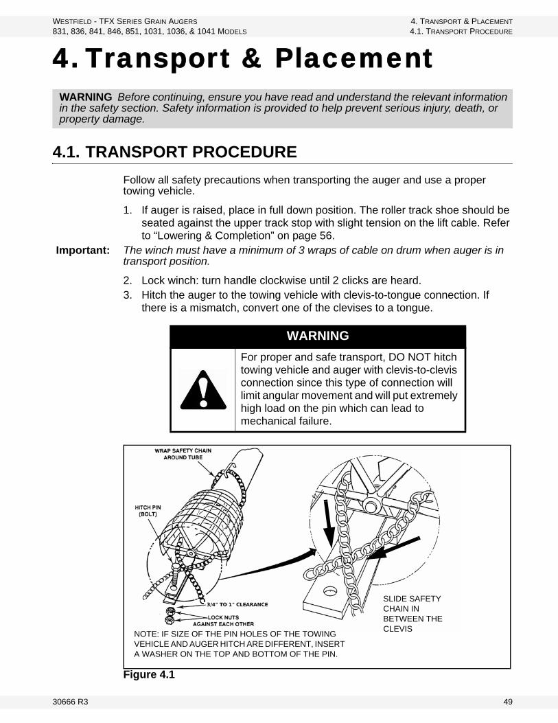
Figure 4.1
WARNING Before continuing, ensure you have read and understand the relevant information in the safety section. Safety information is provided to help prevent serious injury, death, or property damage.
WARNING
For proper and safe transport, DO NOT hitch towing vehicle and auger with clevis-to-clevis connection since this type of connection will limit angular movement and will put extremely high load on the pin which can lead to mechanical failure.
NOTE: IF SIZE OF THE PIN HOLES OF THE TOWING VEHICLE AND AUGER HITCH ARE DIFFERENT, INSERT A WASHER ON THE TOP AND BOTTOM OF THE PIN.
SLIDE SAFETY CHAIN IN BETWEEN THE CLEVIS
30666 R3 49

4. TRANSPORT & PLACEMENT WESTFIELD - TFX SERIES GRAIN AUGERS
4.2. PLACEMENT PROCEDURE 831, 836, 841, 846, 851, 1031, 1036, & 1041 MODELS
4. Place and secure hitch pin. If the towing vehicle has larger pin hole, use the largest pin diameter that will fit through the holes of towing vehicle and auger hitch. Ensure the pin will not slip through the larger holes by inserting a heavy-duty large diameter washer on the top and bottom of the pin.
Important: Use a type of hitch pin (see Figure 4.1) with a load rating that at least matches the carrying capacity of the towing vehicle.
5. Thread the safety chain through the handle on the lower tube, wrapped around the auger and slipped through the clevis (see Figure 4.1) before securely attaching to the towing vehicle. Leave chain slack enough for angular movement.
6. If the distance from the hitch pin to the front or rear chain attachment point is more than 9”, attach an intermediate chain support.
Important: Choose a safety chain rated with minimum strength at least equal to the gross weight of the auger being towed. Ensure the safety chain are not worn out, stretched or kinked.
.
7. Place belt(s) under tension for transport. Refer to “Gas / Electric Motor Mount Installation” on page 34 for more information.
8. PTO models only: Disconnect PTO driveline from tractor and secure in transport saddle.
9. Beware of overhead obstructions and electrical wires and devices. These augers have minimum clearances from 10'–13’ (3.05 m–3.96 m) in normal transport position.
10. Refer to “Transport & Placement Safety” on page 9 for important safety information before towing.
4.2. PLACEMENT PROCEDURE
1. Ensure towing hitch is in place and secure.
WARNING
To prevent accidental break away of the auger that could result to death and serious injury or implement damage, DO NOT tow the auger without securing the hitch pin and without a properly sized and undamaged safety chain.
WARNING
If auger wheels are partially or fully buried in snow or grain, failure to clear area around the wheels before moving may cause damage to the auger or result in serious injury.
50 30666 R3

WESTFIELD - TFX SERIES GRAIN AUGERS 4. TRANSPORT & PLACEMENT
831, 836, 841, 846, 851, 1031, 1036, & 1041 MODELS 4.2. PLACEMENT PROCEDURE
Important: Use a type of hitch pin (see Figure 4.1) that will not allow auger to separate from towing vehicle.
2. Before raising or positioning auger, make sure that entire area in line of travel, both on the ground and overhead, is clear of any obstructions or electrical wires.
3. Place auger on reasonably level ground when raising, lowering, or positioning.
. Note: Make certain cable is properly seated in cable groove before raising auger.
4. To raise auger, turn winch handle clockwise. Use a firm grip on winch handle; do not release unless the ratchet pawl is fully engaged.
Important: Winch must make clicking sound when raising auger. If clicking stops, retain grip on handle, lower auger fully, and repair ratchet.
5. Move the auger into working position slowly. Do not unhitch and attempt to move auger by hand.
6. Once auger is in position, chock wheels on both sides and apply the park brake on the tractor (or chock its wheels as well) to prevent movement during operation.
Important: When releasing auger from the towing vehicle, test the intake end for downward weight. Do not raise the intake end above drawbar height. When the intake end is elevated too high with auger in raised position, the balance of weight quickly transfers to the discharge end, causing it to upend. Ensure proper anchoring/support.
Important: PTO models only: The PTO driveline is a non-separable type. Remove from tractor and secure in the transport saddle on auger before moving tractor away from auger.
WARNING
If auger wheels are partially or fully buried in snow or grain, failure to clear the area around the wheels before moving may cause damage to the auger or result in serious injury.
NOTICE
Do not turn winch handle counter-clockwise except when lowering auger, or severe damage will occur.
WARNING
Never attempt to increase height of auger by positioning wheels on lumber, blocks, or by any other means. To do so will result in damage to equipment and/or personal injury.
30666 R3 51
4. TRANSPORT & PLACEMENT WESTFIELD - TFX SERIES GRAIN AUGERS
4.2. PLACEMENT PROCEDURE 831, 836, 841, 846, 851, 1031, 1036, & 1041 MODELS
7. When operating auger in the raised position, tie to bin to prevent wind from toppling auger. When operating the auger in a freestanding position, anchor the intake end.
8. Anchor and/or support auger during operation.• When lower half of auger empties of grain, the weight balance transfers
to upper end of auger, which can cause upending.
9. Refer to “Lowering & Completion” on page 56 for correct lowering procedure.
WARNING
Do not use auger as a hoist to raise any object regardless of weight. This will create an unsafe condition and will void warranty.
52 30666 R3

WESTFIELD - TFX SERIES GRAIN AUGERS 5. OPERATION
831, 836, 841, 846, 851, 1031, 1036, & 1041 MODELS 5.1. PRE-OPERATIONAL CHECKLIST
5. Operation
5.1. PRE-OPERATIONAL CHECKLIST
Before operating auger each time, the operator must confirm the following:
• All fasteners are secure as per assembly instructions.• PTO driveline is connected and secure (where applicable).• PTO driveline shield rotates freely (where applicable).• Drive belt(s) are not frayed or damaged.• Drive belt(s) are properly adjusted and aligned.• Lift cable is not frayed or damaged.• Lift cable is properly seated in cable sheaves.• Cable clamps are secure.• Tube alignment is reasonably straight.• Auger wheels are chocked, and if necessary, tractor wheels are chocked
or the parking brake has been engaged.• Intake area and discharge spout are free of obstructions.• Proper maintenance has been performed.
5.2. AUGER DRIVE & LOCKOUT PROCEDURE
WARNING Before continuing, ensure you have read and understand the relevant information in the safety section. Safety information is provided to help prevent serious injury, death, or property damage.
Drive Type Before Operation Lockout
Electric Motor
Before starting motor, ensure
• motor is properly grounded• belt release lever is disengaged
so that the belt(s) are released from lower motor pulley
• pulley guards are in place and secure
The electric motor should be equipped with a main power disconnect switch capable of being locked in the off-position only. The switch should be in the locked position during shutdown or whenever maintenance is performed on the auger.
• If reset is required, disconnect all power before resetting motor.
30666 R3 53

5. OPERATION WESTFIELD - TFX SERIES GRAIN AUGERS
5.3. OPERATING PROCEDURE 831, 836, 841, 846, 851, 1031, 1036, & 1041 MODELS
5.3. OPERATING PROCEDURE
5.3.1. START-UP & BREAK-IN
BREAK-IN
1. Complete the pre-operational checklist at the beginning of this chapter. If everything is satisfactory, prepare for a 30-minute operation at half speed (PTO and gas models).
2. Correctly position portable grain hopper and secure it to the auger with both straps (where applicable).
Important: Anchor and/or support auger during operation. When lower half of auger empties of grain, the weight balance transfers to the upper end of auger, which can cause upending.
Gas Engine
Before starting engine, ensure
• gas tank is properly closed• belt release lever is disengaged
so that the belt(s) are released from lower motor pulley
• area surrounding auger is prop-erly ventilated
• pulley guards are in place and secure
Shut down and lock out power source.
a. For engines with a rope or crank start, remove the spark plug wire or the spark plug.
b. For engines with an electric start, remove the ignition key, the spark plug wire, or the spark plug.
PTO Driveline
Before starting, ensure
• PTO driveline is securely attached to the tractor and jack-haft
• tractor park brake in engaged and/or wheels are chocked
• you are not exceeding the maxi-mum operating length of 64” (1610 mm) of the PTO driveline or maximum angle of 15°
• PTO drive on the tractor is in the off position
Shut off tractor’s engine and remove key from tractor.
• If removing key is impossible, remove PTO driveline from trac-tor.
Drive Type Before Operation Lockout
CAUTION
Do not start auger until area is clear of all unauthorized personnel.
Do not exceed 540 rpm on the PTO.
54 30666 R3
WESTFIELD - TFX SERIES GRAIN AUGERS 5. OPERATION
831, 836, 841, 846, 851, 1031, 1036, & 1041 MODELS 5.3. OPERATING PROCEDURE
3. Start tractor and engage PTO driveline or start electric motor or gas engine if applicable, then feed grain to auger. If auger functions normally, check at varying speeds for a period of 30 minutes (PTO and gas models).
Important: When starting auger for the first time, be prepared for an emergency shutdown in case of excessive vibration or noise. Note that auger may run rough until tube is polished.
4. Upon completion of initial run, shut down auger. See “Shutdown” on page 56. for more information on shutting down your auger.
5. Lock out power source and conduct a complete inspection of auger following the checklist at the beginning of this chapter.
After the initial start-up and inspection, the auger should be shut down and inspected at least three times during the first 10 hours of operation.
Keep operation of empty auger to a minimum, as this results in excessive wear.
Once auger is broken in, the checklist should be a part of the daily routine before operating auger.
5.3.2. OPERATING WITH A FULL LOAD
1. When operating the auger, always work with a second person in a position to monitor the operation and initiate a shutdown in case of emergency.
2. Monitor the auger during operation for abnormal noises or vibrations.3. Shut off and lockout all power before making adjustments, servicing, or
clearing the machine.
DANGER
Rotating Flighting Hazard!
To prevent death or serious injury:• Keep away from rotating auger flighting.• Do not remove or modify auger flighting
guards, doors, or covers. Keep in good working order. Have replaced if damaged.
• Do not operate the auger without all guards, doors, and covers in place.
• Never touch the auger flighting. Use a stick or other tool to remove an obstruc-tion or clean out.
• Shut off and lock out power to adjust, ser-vice, or clean.
30666 R3 55

5. OPERATION WESTFIELD - TFX SERIES GRAIN AUGERS
5.3. OPERATING PROCEDURE 831, 836, 841, 846, 851, 1031, 1036, & 1041 MODELS
5.3.3. SHUTDOWN
NORMAL SHUTDOWN
1. Near the end of a load, reduce the feed of grain and decrease auger speed (when possible) until auger is clear of all grain.
2. Disengage belt release and stop engine / motor, or disengage PTO.3. Shut down and lock out power source.
Important: The flighting rpm on augers equipped with electric motors is not adjustable. To clear auger of grain, decrease the grain flow until auger is clear and stop motor.
EMERGENCY SHUTDOWN / FULL-TUBE RESTART:
1. If the auger is shut down for an emergency, lock out motor (gas / electric) or tractor (PTO models) before correcting the problem.
• If the problem is plugging, clear as much of the grain as possible using a piece of wood, wet/dry vac, or other tool before restarting auger. Do not reach in and use your hands (see “Auger Drive & Lockout Procedure” on page 53 for lockout procedure.)
2. If auger is full of grain, do not restart at full speed. Engage the belt release gradually until normal operating speed is reached.
5.3.4. LOWERING & COMPLETION
At the completion of an operation, the auger should be moved to the next work area or to a storage area. After operation:
1. Clean entire work area.2. Remove all supports and chocks.3. Move auger out of working position and lower fully (see shaded box that
follows for lowering procedure).4. Move auger to the next work area or to a storage area and then clean out.
NOTICE
Starting the auger under load may result in damage to unit. Be sure there is no blockage.
56 30666 R3

WESTFIELD - TFX SERIES GRAIN AUGERS 5. OPERATION
831, 836, 841, 846, 851, 1031, 1036, & 1041 MODELS 5.4. HORSEPOWER REQUIREMENTS
5. Clean out auger.a. Shut off tractor engine (PTO models) or shut off motor (gas / electric) and
lock out power.
b. Manually clean out grain with a piece of wood, wet/dry vacuum, or other tool. Do not use hands.
6. Prepare for transport and placement or storage (see “Transport & Placement” on page 49 or “Maintenance & Storage” on page 59 for more information).
5.4. HORSEPOWER REQUIREMENTS
LOWERING
1. For PTO drives: disconnect driveline from tractor before lowering.2. Ensure area beneath auger is clear.3. Turn winch counterclockwise to lower (there will be no clicking sound when
lowering).4. After lowering, turn handle clockwise until you hear 2 clicks to lock brake.
• Use a firm grip on handle. Do not release unless ratchet pawl is fully engaged.
• The winch is designed for manual operation only.• When lowering, never continue to turn handle counterclockwise if the
cable does not keep moving out under load. This will disengage the brake mechanism and create an unsafe condition. If this happens, winch in slack cable and correct problem.
Do not leave auger in raised position when not in use. Auger could drop rapidly due to a cable break. High winds may also upset auger.
Table 5.1 a
a. With dry grain. High moisture grain will require more horsepower.
8” 10”Gas Electric Gas Electric
31’ 16 5 20 7.5-1036’ 16 5-7.5 20-25 1041’ 16 5-7.5 20-25 10-1546’ 18 7.5 — —51’ 18 7.5 — —
30666 R3 57

5. OPERATION WESTFIELD - TFX SERIES GRAIN AUGERS
5.4. HORSEPOWER REQUIREMENTS 831, 836, 841, 846, 851, 1031, 1036, & 1041 MODELS
58 30666 R3

WESTFIELD - TFX SERIES GRAIN AUGERS 6. MAINTENANCE & STORAGE
831, 836, 841, 846, 851, 1031, 1036, & 1041 MODELS 6.1. GENERAL MAINTENANCE PROCEDURES
6. Maintenance & Storage
Proper maintenance habits on the TFX auger mean a longer life, better efficiency, and safer operation. Please follow the guidelines below.
6.1. GENERAL MAINTENANCE PROCEDURES
WARNING Before continuing, ensure you have read and understand the relevant information in the safety section. Safety information is provided to help prevent serious injury, death, or property damage.
Area Maintenance Procedure Frequency
General While auger is in use, observe the checklist on page 53. Daily
GeneralCheck all operating, lifting, and transport components. Replace damaged or worn parts before using auger.
For replacement instructions, see Chapter 3.Regularly
Lift CableCheck and replace if frayed or damaged. Make sure cable clamps are secure.
Periodically
Wheel Hubs Repack with lithium-based grease. Every 2–3 years
Tire PressureCheck with a pressure gauge. Pressure should be main-tained according to side wall recommendations.
Monthly, or if it seems low
Upper Chain Drive
Fill enclosed upper drive housing with grease.
TFX 831, 836, 841, 846, 851: 750 g / 26 ozTFX 1031, 1036, 1041: 1100g / 40 oz
For continuous use in extreme cold, semi-fluid arctic grease or heavy oil may be used.
Regularly
Drive Chain Adjust-ment
Maintain 1/4” - 1/2” (0.64 cm - 1.27 cm)chain deflection.To adjust, loosen bolts on top bearing in the upper drive housing, adjust chain to proper tension, and re-tighten bolts.
Regularly
Belt Release and Motor Mount Slid-ers
Lubricate with light grease or oil.Regularly
Intake Bushing Grease. Daily
Truss Cables Adjust to keep auger tube reasonably straight (if equipped). As necessary
Belt ReleaseKeep film of silicone lubricant on motor mount pipes and sliding end of push bar for easier release of belt tension.
Often
Cable Pulleys Oil. As needed.
30666 R3 59

6. MAINTENANCE & STORAGE WESTFIELD - TFX SERIES GRAIN AUGERS
6.1. GENERAL MAINTENANCE PROCEDURES 831, 836, 841, 846, 851, 1031, 1036, & 1041 MODELS
To replace drive shaft bearings: remove flangette bolts, split one-piece wood bearing with chisel, then replace with new two-piece wood bearing and replace flangettes.
Winch
Note: Service winch with auger in fully lowered posi-tion and cable slack.
Keep a film of grease on gears. Regularly
Oil the bushings, drum shaft, and ratchet. Take care not to get oil or grease on brake discs. Ser-vice winch with auger in fully lowered position and cable slack.
Occasionally
Replace brake discs if less than 1/16” (1.6 mm) thick. As required
Check for proper ratchet pawl operation.When cranking in (clockwise) = loud clickingWhen cranking out (counterclockwise) = no clicking and ratchet pawl fully engaged into gear teeth
Regularly
PTO Driveline
Check shield and replace if damaged. Regularly
Lubricate both universal joints. After every 8 hours of opera-tion.
Lubricate the center portion of driveline (grease fitting is beneath shield) where applicable. Yearly
Gearbox
Maitain oil level at half full (center of cross shaft) with EP90 lube oil.
Gearbox should be level when checking or refilling.Do not overfill.
Regularly
Drive Belts
Check and replace if frayed or damaged. Regularly
Ensure tension is correct under load.Correct operating tension is the lowest tension at which the belts will not slip under peak load conditions.
Regularly
Area Maintenance Procedure Frequency
TO CHANGE BELTS:
First, shut off and lock out all power!
Gas Engine Drive Electric and PTO Drive
1. Remove engine pulley guard if necessary.
1. Remove jackshaft pulley guard.
2. Disengage belt tensioner handle on belt tenion tuve to loosen belts.
2. Remove motor/PTO pulley guard.
3. Remove old belts and replace.3. Unlock nut and loosen tensioner bolt on motor/PTO mount base.
4. Engage belt tensioner handle to tighten belts.
4. Remove old belts and replace.
5. Replace guards.5. Tighten tensioner bolt on motor mount base and turn nut to lock in place.
6. Replace guards.
60 30666 R3

WESTFIELD - TFX SERIES GRAIN AUGERS 6. MAINTENANCE & STORAGE
831, 836, 841, 846, 851, 1031, 1036, & 1041 MODELS 6.2. GENERAL STORAGE PROCEDURES
6.2. GENERAL STORAGE PROCEDURES
TO PROTECT AUGER IN STORAGE DURING THE OFF SEASON:
1. Lower the auger to the full down position with a slight tension on cable.2. Lubricate all grease fittings per maintenance procedures.3. Inspect auger for damage and note any repairs required. Order replacement
parts from your dealer.4. Check tire pressure and inflate if necessary. See tire side-wall for pressure
recommendations.
5. Where applicable:a. Remove battery and store in a cool, dry place. Recharge periodically as
required.
b. Drain gas tank.
c. Cover engine/motor with plastic to protect from weather.
6. Clean and re-lubricate spline on PTO driveline. Cover PTO driveline with plastic bag to protect it from the weather and place in the transport saddle.
7. Tow auger to storage area. Park and chock wheels.
TO PREPARE AUGER FOR USE AFTER STORAGE:
1. Check tire pressure and inflate if necessary. See tire side-wall for pressure recommendations.
2. Tow auger to worksite.
3. Where applicable:a. Remove protective covering from motor.
b. Remove cover from spline of PTO driveline and re-lubricate.
c. Replace battery in holder (where applicable). When recharging battery, follow the correct procedure as indicated in the battery manual.
4. Check oil level in gearbox and refill if necessary (half full only). Do not overfill.
5. On augers equipped with lubricated upper drive, check level of lubrication annually and add as needed. Refill to plug level.
6. Replace any damaged parts.7. Conduct general maintenance procedures before using auger.
Note: Use only genuine Westfield replacement parts or equivalent. Replacement parts such as intake guards, pulley guards, PTO driveline shields, winches and lift cables Must meet ASAE standards or serious injury may result. Use of unauthorized parts will void warranty. If in doubt, contact Westfield or your Westfield dealer. Do not modify any auger components.
CAUTION
Support discharge end of auger before removing or replacing any parts on the undercarriage.
30666 R3 61

6. MAINTENANCE & STORAGE WESTFIELD - TFX SERIES GRAIN AUGERS
6.2. GENERAL STORAGE PROCEDURES 831, 836, 841, 846, 851, 1031, 1036, & 1041 MODELS
62 30666 R3

WESTFIELD - TFX SERIES GRAIN AUGERS 7. TROUBLESHOOTING
831, 836, 841, 846, 851, 1031, 1036, & 1041 MODELS
7. TroubleshootingProblem Possible Cause Remedy
Excessive noise or vibra-tion.
*Remember to follow proper break-in proce-dures—auger may run rough until tube is pol-ished. If noise is extreme from outset or con-tinuous after several loads of grain are fed, continue with troubleshoot-ing below
Chatter from wooden bearings.
Spray penetrating lubricant between shaft and bearing surface. Bearings will break in over time.*If replacement of a bearing becomes neces-sary, split bearings are available to avoid having to slide all bearings off driveshaft.
Truss cables incorrectly adjusted.
Support end of auger and adjust cables so auger is flat or curves slightly upwards.Check the side to side alignment of the truss cables and adjust as necessary.
Flighting peeled back due to plugging.
Inspect spout end of auger for flight condition. Remove and replace flight sections as neces-sary.
Top drive inadequately lubri-cated.
Fill to appropriate level with grease.Top drive is not designed to be filled with oil.
Bent flighting sections.
Support auger and remove all flight sections. Check for straightness of flighting and flight stubs by rolling across flat concrete section. Straighten stub or replace as necessary. Take care not to bend flighting when reinstalling.
Obstruction in tube.Visually inspect for cloth or trash wrapped around flighting, or buildup of gum from oily crops such as flax or canola.
Drive belts jumping off pulleys.
Motor misaligned.Ensure drive and driven pulleys are correctly aligned.
Belts mismatched.Check manual for correct belt sizes and only replace in pairs.
Belt tension inadequate.Maintain correct tension as per Assembly sec-tion.
Using a lower horsepower motor than recommended.
See manual for recommended motor sizes.
30666 R3 63

7. TROUBLESHOOTING WESTFIELD - TFX SERIES GRAIN AUGERS
831, 836, 841, 846, 851, 1031, 1036, & 1041 MODELS
Shear bolts fail repeatedly.
Incorrect shear bolt type.Replace with correct part number. Westfield shear bolts are specifically designed to provide correct driveline protection.
Shear bolt hole worn out-of-round.
Frequent use of the incorrect shear bolt size can wear the mounting hole creating a “scissor effect,” which will require replacement of the affected parts.
Corn spreaders in bin unable to keep up with auger output.
Slow down auger or remove corn spreaders.
Flighting peeled back as a result of plugging.
Occurs when bin has overfilled, or corn spread-ers restrict end of discharge. Inspect flighting at discharge end of auger. If necessary, replace flighting.
Driveline failure (bearing, gear-box, etc.).
See Maintenance section.
Premature wear on auger tubes.
Auger being run at low capacity or empty for extended period of time.
Frequently occurs on farms using grain wagons. Auger should not be left unattended when filling bins. Depending on application, a belt conveyor may be more appropriate.Bent flighting.
Flighting allowed to wear beyond normal point of replace-ment.
When flighting becomes razor-thin at intake, replacement is critical. Since flight material is double thickness at welded lap joints, high spots on flight occur and can accelerate spot tube wear.
Problem Possible Cause Remedy
64 30666 R3

WARRANTYWestfield Industries Ltd. warrants products of its manufacture against defects in materials or workmanship under normal and reasonable use for a period of one year after date of delivery to the original purchaser.
Our obligation under this warranty is limited to repairing, replacing, or refunding defective part or parts which shall be returned to a distributor or a dealer of our Company, or to our factory, with transportation charges prepaid. This warranty does not obligate Westfield Industries Ltd. to bear the cost of labor in replacing defective parts. Any defects must be reported to the Company before the end of the one year period.
This warranty shall not apply to equipment which has been altered, improperly assembled, improperly maintained, or improperly repaired so as to adversely affect its performance. Westfield Industries Ltd. makes no express warranty of any character with respect to parts not of its manufacture.
The foregoing is in lieu of all other warranties, expressed or implied, including any warranties that extend beyond the description of the product, and the IMPLIED WARRANTY of MERCHANTABILITY is expressly excluded.
WESTFIELD INDUSTRIES LTD.
ROSENORT, MANITOBA
CANADA
R0G 1W0

Part of the Ag Growth International Inc. Group
P.O. Box 39
Rosenort, Manitoba, Canada R0G 1W0
Phone: (866) 467-7207 (Canada & USA) or (204) 746-2396
Fax: (866) 768-4852
website: www.grainaugers.com
email: [email protected]
Copyright AGI - Ag Growth International 2014
Printed in Canada
![Continuous Training for Production ML in the …for continuous pipelines in the TensorFlow Extended (TFX) platform [1]. TFX enables Google’s engineers to reliably run ML in production](https://img.dokumen.tips/doc/110x75/5ec4619e17d06d7cdf35bb17/continuous-training-for-production-ml-in-the-for-continuous-pipelines-in-the-tensorflow.jpg)