Embed Size (px)
Citation preview

بسم اهللا الرمحن الرحيم
An‐Najah National University Faculty of Engineering Computer Engineering
Gradua on Project 2 (Hardware) Documentation:
The Vertex Car
Supervised By: Dr. Raed Al‐Qadi Dr. Loai Malhes
Inst. Haya Sama'nah
Done By: Wafa N. Adham & Manar L. Qamhieh
Monday / 2008‐05‐05
Chapter I
Vertex Virtual Car

Introduction: Our project consists mainly from 3 parts, the car that will be controlled through this project, the virtual hand that will control the car and the wireless modules that the commands will be transmitted through. The car has to follow the movement of the hand, and move around according to the directions of the hand.
Picture of the car built in the project. The following are the Specification of Vertex V‐Car:
1‐ 3 DC motors (2 for the forward/backward movement, the other for le /right movement).
2‐ The weight of the car is 2 Kg, and capable of carrying up to 3 Kg. 3‐ PIC 16F877 as a controller. 4‐ Wireless communication with distance can reach 1 mile (1500 m). [Xbee –Pro] 5‐ Ability to move in all directions forward , backward , left , right 6‐ Speed control led using PWM. 7‐ Ba ery 4.5 Ah (Rechargeable). 8‐ Charger.
This part from the project is the car that will be controlled by the other parts of the project (either the PC or the virtual hand controller).
The car can move in 4 direc ons: forward, backward, le and right, and with different speeds. This car can represents any object that can be controlled by the virtual hand, and many applications maybe added to this car, a camera maybe added to transmit a pictures or videos from the path, or anything else.
The car will communicate with the PC and the virtual hand using a wireless module (XBeePro).
Microcontroller Specifications:
The microcontroller used in the project is PIC16f877 at 20MHz opera ng frequency, and the CCP option is used from it to control the motors.
CCP op on is supported by PIC16f877 hardware, and we used the PWM mode of the CCP, so as to generate a square pulse with frequency and duty cycle determined by the code.
Motors Specifications:
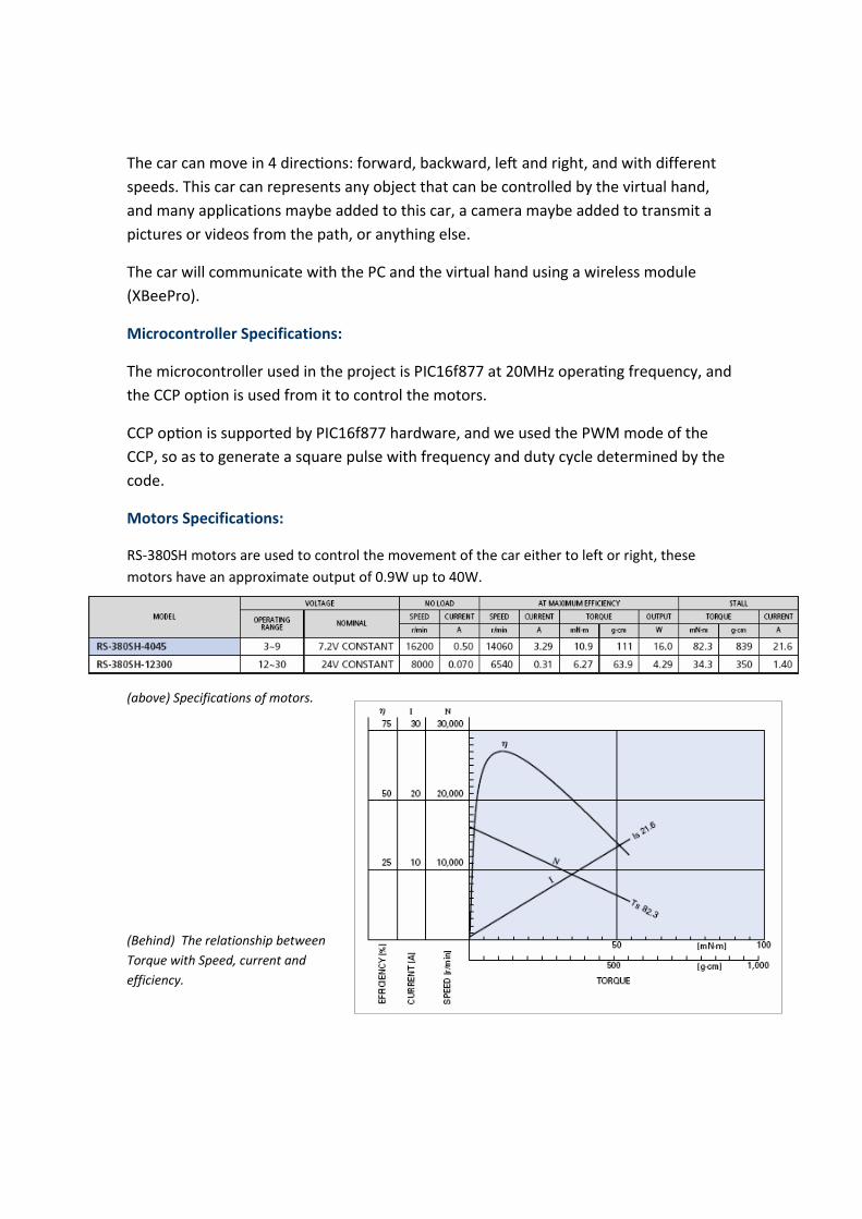
RS‐380SH motors are used to control the movement of the car either to left or right, these motors have an approximate output of 0.9W up to 40W.
(above) Specifications of motors.
(Behind) The relationship between Torque with Speed, current and efficiency.

The motors used to move the car are 3 DC motors, 2 of them are used together to move the car in the forward or the backward direction, and the other motor is used to determine the direction of the car, either to move left or right.
The operating voltage for the speed motors to move the car with load between 2‐5Kg is 6 volts with current almost equals 3.5A.
Each motor has a small circuit, built to control the direction of the motor, and to determine the speed of the DC motor, each circuit consist of the following: 1 – Power Transistor. 2 – 2 Relays. 3 – Diode, capacitor and resistor.
Advantages of this circuit:
There is no much component in this circuit, and we used one power transistor to move the car left or right, and another one for both motors of the forward or backward.
And the PWM signal comes from the PIC16f877 to the gate of the power transistor, so as to run the motor or stop it.
The 2 relays are used so as to give the motors a positive or negative voltage. The motor has a separate power supply of 6 volts and current 4A.

This circuit receives a PWM signal from the PIC, which controls the transistors, and another control signal so as to control the relays and allow the current to pass in 2 ways and change the direction of the motor.
Problems:
1‐ The main problem faced us in our work with motors, was the current needed to make the motors work with load, it was measured to be approximately 4A, it was solved by using a rechargeable ba ery which can produce 6volts and 4.5 A, and it weighs 2Kg.
2‐ In the electrical circuit, we meant the wires to be wide, so as to allow the huge current to pass through them. And in the PCB the routers of the power and the motors interface were made wider.
3‐ Due to the huge current used in the circuit, the heat dissipated from the power transistor was huge, that was solved by using heat sinks.
4‐ The control signals from the PIC16f877 were weak signals, and its current was not able to interface the motors, but we solved this problem by using CMOS inverters 7404, to derive the signal and strength the current.
PCB Design:
We have used the Orcad Layout program to draw the Printed Circuit boards for both the motors' interface circuits and the basic circuits with XbeePro boards.
The advantage of the PCB is that there are no wires in the boards that the connections are much stable and the range of error is limited.
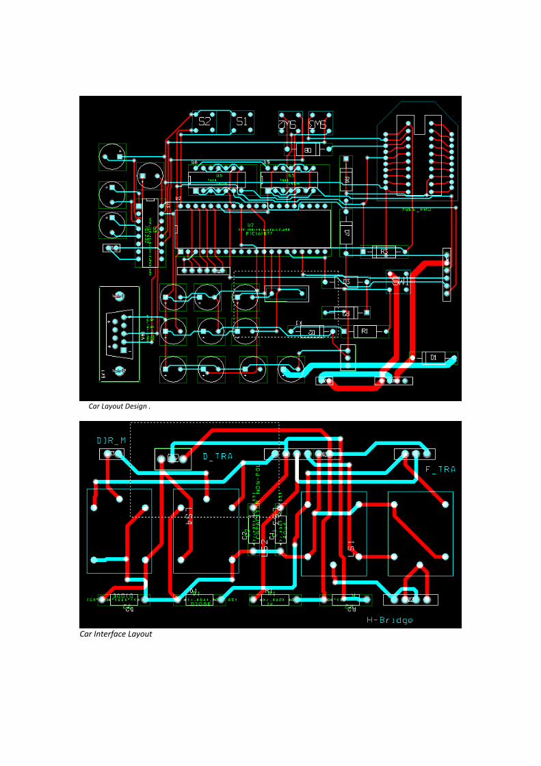
The Following are the schematics for the Car Circuit including the basic circuit and the Car Interface with the PIC.
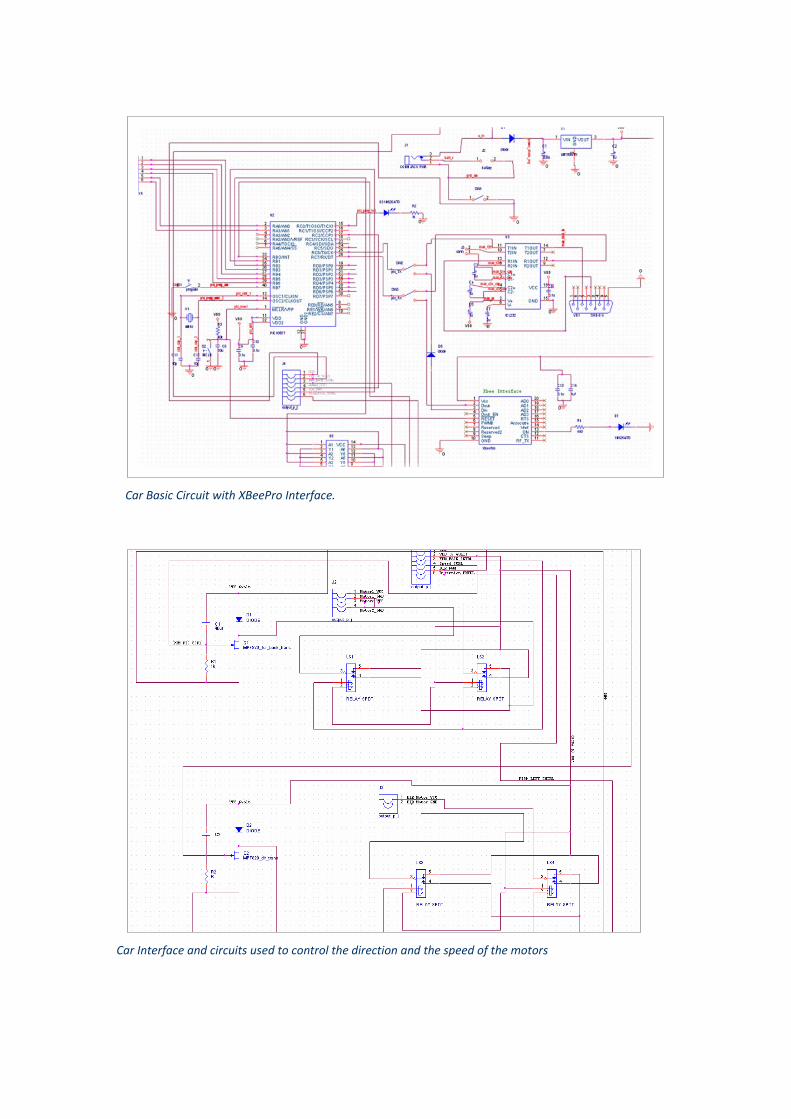
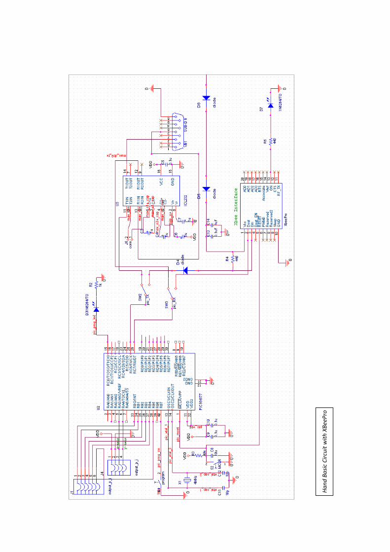
Car Basic Circuit with XBeePro Interface.
Car Interface and circuits used to control the direction and the speed of the motors
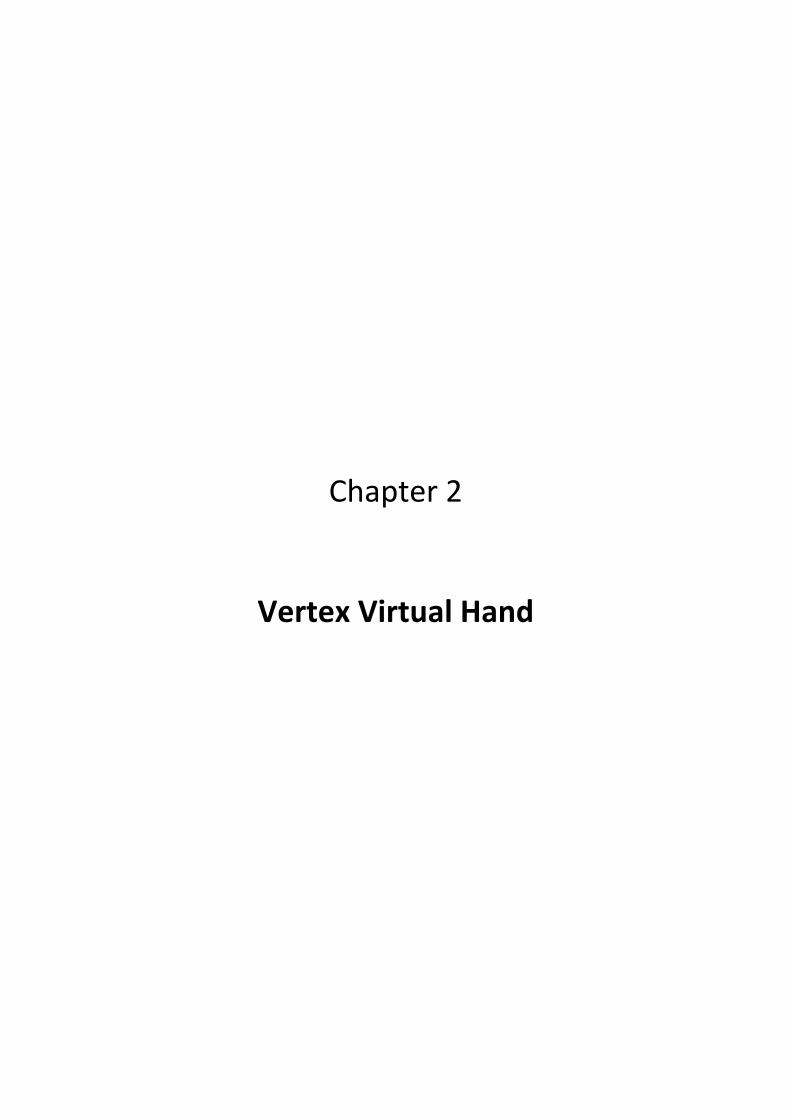
Car Layout Design .
Car Interface Layout
Chapter 2
Vertex Virtual Hand

Introduction:
This is the controller part in the project, and will control the car virtually by sending commands through wireless communication according to the movement and the slope of the hand.
The IC used to detect the movement of the hand is ADXL202, Dual Axis Accelerometer.
ADXL202 are low cost, low power, complete 2‐axis accelerometers with a measurement range of ±2 g. and it can measure both dynamic acceleration (e.g., vibration) and static acceleration (e.g., gravity), and in our project we used the static acceleration.
Most important features in the ADXL202 are:
1‐ 2‐Axis Acceleration Sensor on a Single IC Chip Measures Static Acceleration as Well as Dynamic Acceleration.
2‐ Duty Cycle Output with user Adjustable Period, Low power < 0.6 mA.
3‐ Faster response than Electrolytic, Mercury or Thermal Tilt sensors.
4‐ Bandwidth adjustment with a single capacitor per axis.
ADXL202 Normal Response due to gravity.
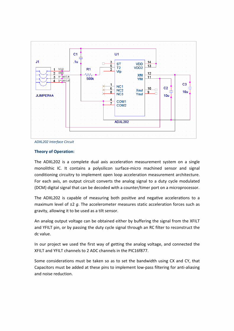
ADXL202 Interface Circuit
Theory of Operation:
The ADXL202 is a complete dual axis accelera on measurement system on a single monolithic IC. It contains a polysilicon surface‐micro machined sensor and signal conditioning circuitry to implement open loop acceleration measurement architecture. For each axis, an output circuit converts the analog signal to a duty cycle modulated (DCM) digital signal that can be decoded with a counter/timer port on a microprocessor.
The ADXL202 is capable of measuring both posi ve and nega ve accelera ons to a maximum level of ±2 g. The accelerometer measures static acceleration forces such as gravity, allowing it to be used as a tilt sensor.
An analog output voltage can be obtained either by buffering the signal from the XFILT and YFILT pin, or by passing the duty cycle signal through an RC filter to reconstruct the dc value.
In our project we used the first way of getting the analog voltage, and connected the XFILT and YFILT channels to 2 ADC channels in the PIC16f877.
Some considerations must be taken so as to set the bandwidth using CX and CY, that Capacitors must be added at these pins to implement low‐pass filtering for anti‐aliasing and noise reduction.

The equa on for the 3 dB bandwidth is:
So we used capacitors with .10µF values, so as to give us a bandwidth with 50Hz.
And also the resistor connected to the T2 pin is called Rset, and it should always be included, even if only an analog output is desired. Use an RSET value between 500 kΩ and 2 MΩ when taking the output from XFILT or YFILT.
PIC‐C Code:
Here is the code we wrote to read the analog values from the accelerometer and convert it to digital values by using the ADC channels in PIC16F877.
void adxl_read_x( ) float value , voltage, sum =0; int I; for (i =0;i<5;i++) // take several readings and get the average voltage = read_adc(); // read the ADC channel specified in the // MAIN value= (5*voltage); value = value / 1024 ; value = value *10; sum = sum+value; delay_ms(10); restart_wdt(); sum = sum / 5; if (sum >= 6.15 && sum <= 6.30) if (x != 0) // Make sure that the command will not be executed // twice printf("s"); // Send the command to stop the car x = 0;
else if … // continue all the cases …
Han
d Ba
sic Circuit w
ith XBe
ePro

Layout of Hand Basic Circuit.
ADXL202 Interface.
Chapter 3
XBee Wireless Module
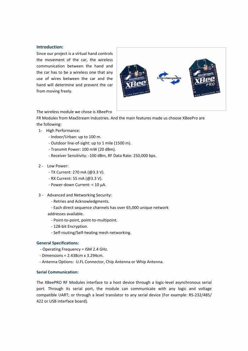
Introduction: Since our project is a virtual hand controls the movement of the car, the wireless communication between the hand and the car has to be a wireless one that any use of wires between the car and the hand will determine and prevent the car from moving freely.
The wireless module we chose is XBeePro FR Modules from MaxStream Industries. And the main features made us choose XBeePro are the following: 1‐ High Performance: ‐ Indoor/Urban: up to 100 m. ‐ Outdoor line‐of‐sight: up to 1 mile (1500 m). ‐ Transmit Power: 100 mW (20 dBm). ‐ Receiver Sensitivity: ‐100 dBm, RF Data Rate: 250,000 bps.
2 ‐ Low Power: ‐ TX Current: 270 mA (@3.3 V). ‐ RX Current: 55 mA (@3.3 V). ‐ Power‐down Current: < 10 μA.
3 ‐ Advanced and Networking Security: ‐ Retries and Acknowledgments. ‐ Each direct sequence channels has over 65,000 unique network addresses available. ‐ Point‐to‐point, point‐to‐multipoint. ‐ 128‐bit Encryption. ‐ Self‐routing/Self‐healing mesh networking.
General Specifications: ‐ Operating Frequency = ISM 2.4 GHz. ‐ Dimensions = 2.438cm x 3.294cm. ‐ Antenna Options: U.FL Connector, Chip Antenna or Whip Antenna.
Serial Communication:
The XBeePRO RF Modules interface to a host device through a logic‐level asynchronous serial port. Through its serial port, the module can communicate with any logic and voltage compatible UART; or through a level translator to any serial device (For example: RS‐232/485/ 422 or USB interface board).

Each data byte consists of a start bit (low), 8 data bits (least significant bit first) and a stop bit (high). The module UART performs tasks, such as timing and parity checking, that are needed for data communications. Serial communications depend on the two UARTs to be configured with compatible settings (baud rate, parity, start bits, stop bits, data bits).
Transmit and Receive Modes:
‐ Unicast Mode: Unicast Mode enables acknowledged communications. While in this mode, receiving modules send an ACK (acknowledgement) of RF packet reception to the transmitter. If the transmitting module does not receive the ACK, the transmitter will re‐send the packet up to three times until the ACK is received. Unicast Mode is the only mode that supports retries.
‐ Broadcast Mode: Any RF module will accept a packet that contains a broadcast address. When configured to operate in Broadcast Mode, receiving modules do not send ACKs (Acknowledgements) and transmitting RF modules do not automatically re‐send packets as is the case in Unicast Mode. To send a broadcast packet to all modules regardless of 16‐bit or 64‐bit addressing, set destination addresses of all the modules as shown below. Sample Configuration (All modules in the network): ‐ DL (Des na on Low Address) = 0x0000FFFF

‐ DH (Des na on High Address) = 0x00000000.
Connec on between PIC16f877 and XBeePro:
XBeePro has a supply voltage between 2.8 – 3.4 volts, therefore there is a difference between the voltage levels of the PIC and XBeePro, that was one of the problems faced us in connecting the XBee with PIC. The solu on was to use a 3.3 voltage regulator, so as to maintain the XBeePro supply voltage, and as shown in figure below, Din Pin must be taken care of its input voltage, so that we used a diode and a large resistor to transform the 5 volt input voltage to 3.3 volts.
XBeePro Interface with PIC16F877.
Another problem faced us while connec ng XBeePro with PIC16F877, that the transmission rate of XBeePro is much higher than PIC16F877, that the PIC can't operate and execute the commands as they arrive from the XBeePro.
The solu on to that problem was to operate the pic16F877at 20MHz frequency. At this frequency, PIC16F877 can communicate with XBeePro perfectly.

XBee Daughterboard:
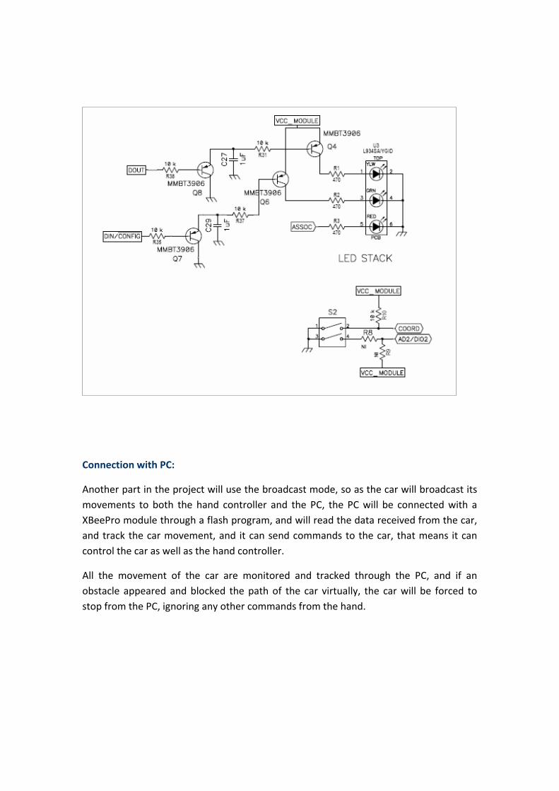
Connection with PC:
Another part in the project will use the broadcast mode, so as the car will broadcast its movements to both the hand controller and the PC, the PC will be connected with a XBeePro module through a flash program, and will read the data received from the car, and track the car movement, and it can send commands to the car, that means it can control the car as well as the hand controller.
All the movement of the car are monitored and tracked through the PC, and if an obstacle appeared and blocked the path of the car virtually, the car will be forced to stop from the PC, ignoring any other commands from the hand.
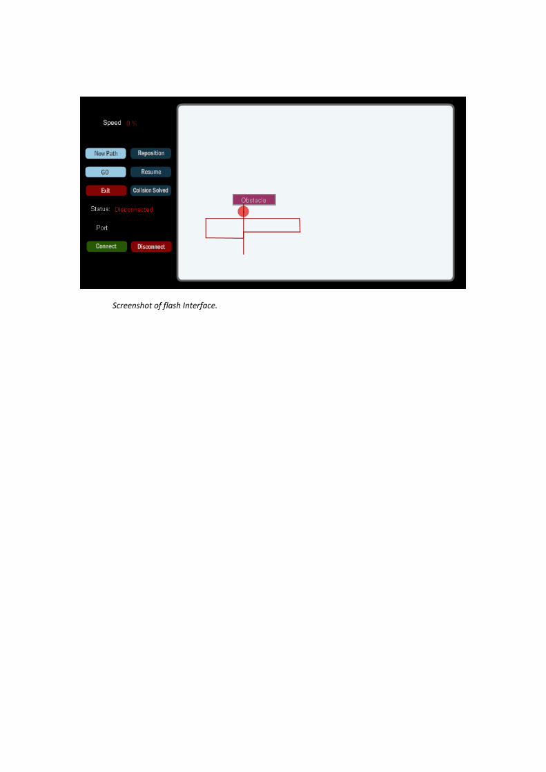
Screenshot of flash Interface.