Embed Size (px)
Citation preview

Governors

Every attempt has been made to ensure that this documentation is as accurate and up-to-date as possible.However, Vertical Express assumes no liability for consequences, directly or indirectly, resulting from any error oromission. The material contained herein is subject to revision. Please report any problems with this manual toVertical Express, P.O. Box 2019, Memphis, Tennessee 38101.
Vertical Express • P.O. Box 2019 • Memphis, Tennessee 38101
© 1999, 2012 Vertical Express. All rights reserved.Published June, 2012
First Edition Printed in the United States of America
Manual Number: 89157 v.1.1

Governors Contents
Printed in USA June, 2012 1
ContentsSafety Precautions . . . . . . . . . . . . . . . . . . . . . . . . . . . . . . . . . . . . . . . . . . . . . . . . . . . . . . . . . . . . . . . . 3
Terms in this Manual . . . . . . . . . . . . . . . . . . . . . . . . . . . . . . . . . . . . . . . . . . . . . . . . . . . . . . . . 3
General Safety . . . . . . . . . . . . . . . . . . . . . . . . . . . . . . . . . . . . . . . . . . . . . . . . . . . . . . . . . . . . . 3
Electrical Safety . . . . . . . . . . . . . . . . . . . . . . . . . . . . . . . . . . . . . . . . . . . . . . . . . . . . . . . . . . . . 3
Mechanical Safety . . . . . . . . . . . . . . . . . . . . . . . . . . . . . . . . . . . . . . . . . . . . . . . . . . . . . . . . . . 4
12” Governor
Governor Selection Chart . . . . . . . . . . . . . . . . . . . . . . . . . . . . . . . . . . . . . . . . . . . . . . . . . . . . . . . . . . . . 8
Rope Dimensions . . . . . . . . . . . . . . . . . . . . . . . . . . . . . . . . . . . . . . . . . . . . . . . . . . . . . . . . . . . 8
Tensile/Torsional Requirements . . . . . . . . . . . . . . . . . . . . . . . . . . . . . . . . . . . . . . . . . . . . . . . . 8
Spring Color / Speed Chart Selection. . . . . . . . . . . . . . . . . . . . . . . . . . . . . . . . . . . . . . . . . . . . . 9
Tailweight Selection Chart . . . . . . . . . . . . . . . . . . . . . . . . . . . . . . . . . . . . . . . . . . . . . . . . . . . . 9
Installation . . . . . . . . . . . . . . . . . . . . . . . . . . . . . . . . . . . . . . . . . . . . . . . . . . . . . . . . . . . . . . . . . . . . . 10
Encoder Sensor Adjustment . . . . . . . . . . . . . . . . . . . . . . . . . . . . . . . . . . . . . . . . . . . . . . . . . . 12
Speed Check of Non-Roped Governors . . . . . . . . . . . . . . . . . . . . . . . . . . . . . . . . . . . . . . . . . . 13
Tailweight Installation . . . . . . . . . . . . . . . . . . . . . . . . . . . . . . . . . . . . . . . . . . . . . . . . . . . . . . 14
Tailweight Locations . . . . . . . . . . . . . . . . . . . . . . . . . . . . . . . . . . . . . . . . . . . . . . . . . . . . . . . . 16
Speed Check of Roped Governor. . . . . . . . . . . . . . . . . . . . . . . . . . . . . . . . . . . . . . . . . . . . . . . 18
Verify the Calibration of Governor Switch and Jaw Activation . . . . . . . . . . . . . . . . . . . . . . . . . . 18
Switch and Jaw Tripping Adjustment. . . . . . . . . . . . . . . . . . . . . . . . . . . . . . . . . . . . . . . . . . . . 18
16” Governor
Machine Information. . . . . . . . . . . . . . . . . . . . . . . . . . . . . . . . . . . . . . . . . . . . . . . . . . . . . . . . 19
Tensile and Torsional Requirements . . . . . . . . . . . . . . . . . . . . . . . . . . . . . . . . . . . . . . . . . . . . 19
Rope Dimensions . . . . . . . . . . . . . . . . . . . . . . . . . . . . . . . . . . . . . . . . . . . . . . . . . . . . . . . . . . 20
Tailweight Selection Chart. . . . . . . . . . . . . . . . . . . . . . . . . . . . . . . . . . . . . . . . . . . . . . . . . . . . 20
Installation . . . . . . . . . . . . . . . . . . . . . . . . . . . . . . . . . . . . . . . . . . . . . . . . . . . . . . . . . . . . . . . . . . . . . 22
Speed Check of Non-Roped Governors . . . . . . . . . . . . . . . . . . . . . . . . . . . . . . . . . . . . . . . . . . 22
Tailweight Installation . . . . . . . . . . . . . . . . . . . . . . . . . . . . . . . . . . . . . . . . . . . . . . . . . . . . . . . 23
Tailweight Locations . . . . . . . . . . . . . . . . . . . . . . . . . . . . . . . . . . . . . . . . . . . . . . . . . . . . . . . . 25
Speed Check of Roped Governor. . . . . . . . . . . . . . . . . . . . . . . . . . . . . . . . . . . . . . . . . . . . . . . 27
Maintenance . . . . . . . . . . . . . . . . . . . . . . . . . . . . . . . . . . . . . . . . . . . . . . . . . . . . . . . . . . . . . . . . . . . . 27

Contents Governors
2 Vertical Express
Contents(continued)
MRL Products
Overspeed Governor (SG-200) . . . . . . . . . . . . . . . . . . . . . . . . . . . . . . . . . . . . . . . . . . . . . . . . 28
12” Self-Resetting Governor (5501AE7) . . . . . . . . . . . . . . . . . . . . . . . . . . . . . . . . . . . . . . . . . 30
12” Self-Resetting Governor . . . . . . . . . . . . . . . . . . . . . . . . . . . . . . . . . . . . . . . . . . . . . . . . . . 30
Non-Digital Counterweight (5501AE5) . . . . . . . . . . . . . . . . . . . . . . . . . . . . . . . . . . . . . . . . . . . 30
Governor Tailweight Assembly . . . . . . . . . . . . . . . . . . . . . . . . . . . . . . . . . . . . . . . . . . . . . . . . 31
5503AK001, Left Hand . . . . . . . . . . . . . . . . . . . . . . . . . . . . . . . . . . . . . . . . . . . . . . . . . . 31
5503AK101, Right Hand . . . . . . . . . . . . . . . . . . . . . . . . . . . . . . . . . . . . . . . . . . . . . . . . . 32
Governor Kits . . . . . . . . . . . . . . . . . . . . . . . . . . . . . . . . . . . . . . . . . . . . . . . . . . . . . . . . . . . . . 33
Replacement Parts
12” Governor 5501AF Low Speed, 5501AE High Speed . . . . . . . . . . . . . . . . . . . . . . . . . . . . . . 35
12” Tailweight Sheave . . . . . . . . . . . . . . . . . . . . . . . . . . . . . . . . . . . . . . . . . . . . . . . . . . . . . . 36
12” Remote Governor Reset Assembly, 200APD . . . . . . . . . . . . . . . . . . . . . . . . . . . . . . . . . . . 37
12” Governor Solenoid Kit, 200APJ . . . . . . . . . . . . . . . . . . . . . . . . . . . . . . . . . . . . . . . . . . . . . 38
16” Governor, 5501AA Digital, 5501AB Non-Digital . . . . . . . . . . . . . . . . . . . . . . . . . . . . . . . . . 39
16” Tailweight Sheave, 5503AH3, 128813 . . . . . . . . . . . . . . . . . . . . . . . . . . . . . . . . . . . . . . . 40
Tailweight Tie-Down Package, 148313 . . . . . . . . . . . . . . . . . . . . . . . . . . . . . . . . . . . . . . . . . . 41
Kits/Assemblies . . . . . . . . . . . . . . . . . . . . . . . . . . . . . . . . . . . . . . . . . . . . . . . . . . . . . . . . . . . 42

Governors Safety Precautions
Printed in USA June, 2012 3
Safety Precautions
IMPORTANT! Read this page before any work is performed on elevator equipment. The procedures contained in this manual are intended for the use of qualified elevator personnel. In the interest of your personal safety and the safety of others, do not attempt any procedure that you are not qualified to perform.
All procedures must be accomplished in accordance with the applicable rules in the latest edition of the National Electrical Code, the latest edition of ASME A17.1, and any governing local codes.
Terms in This Manual
CAUTION statements identify conditions that may result in damage to the equipment or other property if improper procedures are followed.
WARNING statements identify conditions that may result in personal injury if improper procedures are followed.
General Safety
Before applying power to the controller, check that all factory wire connections are tight on relays, contactors, fuse blocks, resistors, and terminals on cards and DIN rail terminals. Connections loosened during shipment may cause damage or intermittent operation.
Other specific warnings and cautions are found where applicable and do not appear in this sum-mary. See the Elevator Industry Field Employees’ Safety Handbook for electrical equipment safety information on installation and service.
Electrical Safety All wiring must be in accordance with the National Electrical Code and be consistent with all state and local codes.
Use the Proper Fuse
To avoid fire hazards, use only a fuse of the correct type, voltage, and current rating. See the job specific drawings sheet (Power Supplies) for fusing information.
Electric shocks can cause personal injury or loss of life. Circuit breakers, switches, and fuses may not disconnect all power to the equipment. Always refer to the wiring diagrams. Whether the AC supply is grounded or not, high voltage will be present at many points.
Printed Circuit Cards
Printed circuit boards may be damaged if removed or installed in the circuit while applying power. Before installation and/or removing printed circuit boards, secure all power.
Always store and ship printed circuit cards in separate static bags.
Safety Precautions Governors
4 Vertical Express
(continued)(continued)Electrical Safety Mainline Disconnect
Unless otherwise directed, always Turn OFF, Lock, and Tag out the mainline disconnect to remove power from elevator equipment. Before proceeding, confirm that the equipment is de-energized with a volt meter. Refer to the Vertical Express Employees’ Safety and Accident Prevention Program Manual for the required procedure.
Test Equipment Safety
Always refer to manufacturers’ instruction book for proper test equipment operation and adjust-ments.
Megger or buzzer-type continuity testers can damage electronic components. Connection of devices such as voltmeters on certain low level analog circuits may degrade electronic system per-formance. Always use a voltmeter with a minimum impedance of 1M Ohm/Volt. A digital voltmeter is recommended.
When Power Is On
To avoid personal injury, do not touch exposed electrical connections or components while power is ON.
Mechanical Safety See the Elevator Industry Field Employees’ Safety Handbook for mechanical equipment safety information on installation and service.

Governors Safety Precautions
Printed in USA June, 2012 5
Static Protection Guidelines
IMPORTANT! Read this page before working with electronic circuit boards.
Elevator control systems use a number of electronic cards to control various functions of the elevator. These cards have components that are extremely sensitive to static electricity and are susceptible to damage by static discharge.
Immediate and long-term operation of an electronic-based system depends upon the proper handling and shipping of its cards. For this reason, the factory bases warranty decisions on the guidelines below.
Handling • Cards shipped from the factory in separate static bags must remain in the bags until time for installation.
• Anti-static protection devices, such as wrist straps with ground wire, are required when handling circuit boards.
• Cards must not be placed on any surface without adequate static protection.
• Only handle circuit cards by their edges, and only after discharging personal static electricity to a grounding source. DO NOT touch the components or traces on the circuit card.
• Extra care must be taken when handling individual, discrete components such as EPROMS (which do not have circuit card traces and components for suppression).
Shipping • Complete the included board discrepancy sheet.
• Any card returned to the factory must be packaged in a static bag designed for the card.
• Any card returned to the factory must be packaged in a shipping carton designed for the card.
• “Peanuts” and styrofoam are unacceptable packing materials.
Note: Refer to the Vertical Express Replacement Parts Catalog to order extra static bags and shipping cartons for each card.
Failure to adhere to the above guidelines will VOID the card warranty!
Arrival of Equipment Receiving
Upon arrival of the equipment, inspect it for damage. Promptly report all visible damage to the carrier. All shipping damage claims must be filed with the carrier.
Storing
During storage in a warehouse or on the elevator job site, precautions should be taken to protect the equipment from dust, dirt, moisture, and temperature extremes.
Revision Change Bars
Each revised page included in this manual will have a vertical line (change bar) to the left of the text that has been added or changed. The example at the left of this paragraph shows the size and position of the revision change bar.

Safety Precautions Governors
6 Vertical Express
This page
intentionally
left blank.

Governors 12” Governor
Printed in USA June, 2012 7
12” Governor
Machine Information Rope Specifications
• Travel - Up to 700 feet
• Rated Speed - Up to 1200 FPM
• Encoder Option - Digital Encoder Available
• Counterweight or Car
• Single or Double Switch Option Available
• Switch Rating - 60 VDC, 5A; 250VAC 15A
• Pull Through - 400 lbs.
• Rope Size - 3/8” 8 x 19
• Iron or Traction Steel Grade
1/2” - 8 x 19 Seale
1/2” - 8 x 25 Wire
1/2” - 8 x 19 Seale
• Grades and Construction
Eight strand wire rope with vegetable fiber core
8 x 25 filler wire
8 x 19 Seale
Right regular lay (unless otherwise specified)
Length of rope lay cannot exceed 6 3/4 times nominal rope diameter
Vegetable core is hard vegetable fibers, No jute fibers
Evenly twisted, uniform fly
RopeGripCarrier
Grip Actuator
Lead Seals
Adjustment Spring
Sheave
Guard
OptionalSwitch
SwitchAssembly
Shim (as received)
Bushing
Clevis Pin
Dog Link
Clevis Pin
Rope Grip Jaw
Nameplate
Base
Jaw and Switch Tripping Weight(cast iron weights shown)

Governor Selection Chart Governors
8 Vertical Express
Governor Selection Chart
Rope Dimensions
Tensile/Torsional Requirements
Net Travel (Feet)
Rated Speed (FPM)
Assembly Numbers
Standard Digital Non-Digital Counterweight
0-700 0-12005501AF
5501AE1 5501AE2 5501AE3
0-700 0-500 5501AE4 NA 5501AE5
0-850 0-200 — 5501AA15501AA2 5501AB1 5501AB1
0-850 201-400 — 5501AA35501AA4 5501AB2 5501AB2
0-850 401-600 — 5501AA55501AA6 5501AB3 5501AB3
0-850 601-1200 — 5501AA75501AA8 5501AB4 5501AB4
0-850 1201-4000 — 5501AA95501AA10 5501AB5 5501AB5
Synergy 85S 5501AJ001
Synergy 100/300R Synergy 100/300S 5501AE7
Rope Diameter (in.) Loaded Rope Unloaded Rope Out of Round Tolerances
.375 .375/.390 .382/.390 .009
.500 .500/.515 .510/.525 .013
8 x 19 Class Wire Rope Breaking Strength (lbs.)
Rope Diameter (in.)Approximate
Circumference (in.)Weight
(lbs. per foot) Traction Steel EHS Iron
.250 .750 .09 3,600 4,500 1,800
.313 1.000 .14 5,600 6,900 2,900
.375 1.125 .20 8,200 9,900 4,200
.438 1.375 .28 11,000 13,500 5,600
.500 1.625 .36 14,500 17,500 7,200
Notes:• Wire rope breaking strengths covered by specifications must not be less than these values.• Loaded rope equals 10% of braking strength.
Minimum Tensile Maximum TensileMaximum Hardness
Torsional
P.S.I. N/mm2 P.S.I. N/mm2 Vickers BHN
Iron 100,000 699.5 180,000 1241 NA NA NA
Traction Steel 170,000 1172.1 215,000 1482 450 425 34.5 - 25.0 d
EHS 240,000 1654.7 285,000 1965 565 530 NA
Note: 1KPSI = 6.89476 N/mm2, Maximum tensile strength applies only to the outer strand wires contacting the sheave.

Governors Tailweight Selection Chart
Printed in USA June, 2012 9
Spring Color / Speed Chart Selection
Tailweight Selection Chart
Rated Speed FPM Spring Color Part Number Rated Speed FPM Spring Color Part Number
125 Red 780BA1 500 Brown 780BG1
150 Yellow 780BC1 600 White 780BH1
175 Brown 780BG1 700 Green 780AX1
200 White 780BH1 800 Silver 780BJ1
250 Green 780AX1 900 Blue 780AY1
300 Silver 780BJ1 1000 Black 780BK1
350 Blue 780AY1 1100 Purple 780BL1
400 Black 780BK1 1200 Orange 780BP1
450 Purple 780BL1
Assembly #
Travel SpeedCar
TailweightCounterweight
TailweightTailweightQty / No.
Tension Wt. (lbs)
Sheave Dia.
Rope Construction
Rope Material
Pull Through Tension
5501AF
0-300
0-500
5503AB5
5503AB4
None Req. 156 12.00 .3758 x 19 Seale
Iron or
Steel
400 lbs.
5503AB2
5503AB10
501-12005503AG7
5503AG4 Steel5503AG2
301-700
0-5005503AB7 5503AB8 Iron
or Steel5503AB9 5503AB12
501-12005503AG8 5503AG5
Steel5503AG3 5503AG6
5501A_
0-300
0-500 128800136526 130505 (1)129028 138
16.00
.5008 x 19 Seale or
8 x 25 Filler Wire
Iron or
Steel
600 lbs.
501-8005503AH15503AH2 5503AH4 (1)129027 170
801-1400 Steel
301-700
0-500 1288135503AF1
(2)129028 276
Iron or
Steel5503AF2
501-8005503AH3 5503AH5
5503AH9801-1400 Steel
501-850
0-500 1228135503AF1
(2)129027 340
Iron or
Steel5503AF2
501-8005503AH3 5503AH5
5503AH9801-1400 Steel

12” Governor Installation Governors
10 Vertical Express
12” Governor Installation
1. Check the nameplate to ensure that the governor is designed for a speed range corresponding to the job site specifications. See Figure 1.
Note: Switch and jaw tripping speeds are stamped on the governor nameplate.
2. Mount the governor on a flat, level surface, or use shims to level the governor.
Note: Twisting at the base may cause the jaws to malfunction.
3. Ensure that all seals are intact.
4. Verify that all moving parts function properly.
5. Remove accumulations of dirt or excess grease and oil.
6. Check the job layout for location of governor and tailweight.
Do NOT paint the governor; this could cause it to malfunction.
7. Place the governor in the mounting location, with the jaw in position to correctly engage the governor rope. Do not fasten.
8. Install shims under the governor base to level the base from front-to-rear and side-to-side. See Figure 1.
9. On the car side, drop a plumb line from the center of the governor sheave. Align the governor rope position to the governor rope bracket and the tailweight sheave. If the plumb bob does not align properly, shift the governor until it does. See Figure 2 on page 11.
10. Make sure the centerline of the governor sheave groove is parallel with the back of the guide rail, and then bolt the governor down securely.
Note: The governor should be 1 3/4" behind the rail face.
Figure 1 - Governor Nameplate
Nameplate

Governors 12” Governor Installation
Printed in USA June, 2012 11
Installation(continued)
Figure 2 - 12” Governor (5501AE) and Safety System
3/8 8/19Iron or Traction Steel Wire Rope
Fist Grips
Shackle
Counterweight Detail
Thimble
Level StopScrew
Thimble
FistGrips
Tail Weight Sheave
Hold DownSpring
Rope Lever
Governor Sheave
To Governor
To Lever To Tailweight
Governor Rope Bracket
Cam Rope GripActuator
Cam Retainer
1/16
Stud Rod Turnbuckle Draw Bar Spring Wire Rope Clips
Eye Bolt
MountingPlate
AnchorRope Thimble
Optional Tie Down Assembly
Car Detail
Encoder
Optical Sensor Gauge
Sheave
Encoder Side View
Governor Cam Rope Grip Actuator
TwinClevis Link
Cable 24Tie Down Mount Angle

12” Governor Installation Governors
12 Vertical Express
Encoder Sensor Adjustment Tools and Materials
Figure 3 - Friction Drive Wheel
Encoder cards can be damaged if not aligned properly and then contact is made with the encoder disk.
1. Adjust the vertical sensor-to-disk engagement. See Figure 4.
a. Loosen the four (4) sensor bracket nuts.
b. Vertically adjust the bracket until the encoder disk engages the encoder sensor and the top of the sensor is aligned with the bottom of the engagement depth reference line.
c. Start with the lower left nut, and tighten the four (4) sensor bracket nuts.
2. Check the horizontal front-to-back sensor card position. If necessary, adjust the card position.
a. Loosen the screws holding the card.
b. Insert the provided optical sensor gauge between the sensor and the encoder disk.
c. Adjust the card in and out so that the disk touching the gauge is touching the sensor.
d. Tighten the four (4) card mounting screws.
3. Recheck the vertical and horizontal adjustments.
Figure 4 - Sensor Depth Alignment Detail
4 Diameter RubberDrive Wheel
VariableSpeed Drill
Governor Sheave
TachometerPosition
Rope Pitch Line
• Suitable friction drive wheel
• Variable speed drill
• Tachometer
• "C" clamp or vise grips, and wood blocking
Note: A friction drive wheel can be made. See Figure 3.
Adjust bracket so topof sensor housing isaligned with bottom ofengagement depthreference line.
Adjust card inand out so disktouches gauge,which touchessensor.
Insert gauge betweensensor and encoder disk.
Vertical Adjustment Horizontal Adjustment
Engagement depthreference line
Engagementdepth reference line
Sensor Housing
Card Screws
Sensor Bracket Nuts
Encoder Disk

Governors 12” Governor Installation
Printed in USA June, 2012 13
Speed Check of Non-Roped Governors
Keep fingers and hands clear of the carrier arm when checking tripping speeds.
1. Chuck the drive wheel device in a 3/8" or 1/2" variable speed drill.
2. Hold a tachometer in place against the groove in the governor sheave. The tachometer should touch the approximate center of the sheave groove. See Table 1 for speed specifications.
3. Place the friction drive wheel against the rim of the governor sheave and slowly increase the speed until the governor switch trips.
Ensure that when the weights fly out, the tachometer is not damaged.
4. Record the switch tripping speed.
5. Continue increasing the governor speed until the governor’s rope jaws trip. Record the jaw tripping speed.
Note: The recorded switch/jaw tripping speeds must comply with those listed in the speed specifications, as mandated by code. See Table 1.
Table 1 - Speed Specifications for 12” Governor
Elevator Rated
Speed (FPM)
Governor Tripping Speed 12 Tachometer Reading
Switch Jaws Switch Jaws
100 135 135 146 146
125 175 175 190 190
150 210 210 228 228
175 225 250 244 271
200 250 280 271 303
225 275 308 298 334
250 300 337 325 365
300 350 395 379 428
350 400 452 433 490
400 455 510 493 553
450 510 568 553 615
500 560 625 607 677

Tailweight Installation Governors
14 Vertical Express
Tailweight Installation
1. Locate correct installation detail for specific job type. See Figure 5 and Figure 6 on page 15.
2. Verify correct placement of the governor tailweight location. See Figure 7 on page 16.
Figure 5 - Tailweight Installation Details (1 of 2)
5503AB5 (Car)•0-300 ft. of travel•11/12# rail
5503AB105503AG2•18.5# rail
ITEM PART NO.PRINT NO.DESCRIPTION
1 Tailweight Sheave
2 Tailweight Side Plate
3 Dust Cover
4 Rail Bracket
5 Rope Guard
6 Tailweight Filler
7 Tailweight Switch Kit
7
3
5
6
12
4
5503AB2 (Car)5503AG7•0-300 ft. of travel•15# rail
5503AB4 (Counterweight)5503AG4•0-300 ft. of travel•15/18# rail
7
31 2
4
5503AB_ (0-500 fpm)5503AG_ (501-1200 fpm)

Governors Tailweight Installation
Printed in USA June, 2012 15
Figure 6 - Tailweight Installation Details (2 of 2)
5503AB7 (Car)5503AG8•301-700 ft. of travel•15# rail
5503AB8 (Counterweight)5503AG5•301 -700 ft. of travel•15# rail
5503AB12 (Counterweight)5503AG6•301-700 ft. of travel•18.5# rail
5503AB9 (Car)5503AG3•301-700 ft. of travel•18.5# rail
5503AB_ (0-500 fpm)5503AG_ (501-1200 fpm)

Tailweight Installation Governors
16 Vertical Express
Tailweight Locations
Figure 7 - Tailweight Locations
MAXIMUM TENSION WEIGHT = 156#
11 3/8”(STD.)(VARIABLE
10”-18”)
36”
MIN
. FO
R S
EIS
MIC
TIE
-DO
WN
AS
SY.
12” R.C.
15”
28”
BA
CK
OF
RA
IL
2” (B
.R. S
W.)
4 5/
8” O
UT
TO O
UT
TOP
BO
LTS
(CAR) TAILWEIGHT ASSY.#5503AB2 - 15# RAIL#5503AB10 - 18 1/2# RAIL
LIMITS: NET TRAVEL = 0-300 FT. FPM = 0-1200 FPM
28”
15”
MAXIMUM TENSION WEIGHT = 156#
(CAR) TAILWEIGHT ASSY.#5503AB7 - 15# RAIL#5503AB9 - 18 1/2# RAIL
LIMITS: NET TRAVEL = 300-700 FT. FPM = 0-1200 FPM
36”
MIN
. FO
R S
EIS
MIC
TIE
-DO
WN
AS
SY.
4 5/
8” O
UT
TO O
UT
TOP
BO
LTS12” R.C.
BA
CK
OF
RA
IL``
B''
11 3/8” STD.W/O ENG.APPROVAL
38 1
/2”
O.A
. BA
R G
UID
E A
SS
Y.
10 3
/4”
10 3
/4”
MIN
.35
” M
AX.
17 1
/4”
10 3
/4”
``C
'' FI
LLER
BO
LTS
@B
OTT
OM
FILLERPLATES
``C
'' FI
LLER
BO
LTS
@B
OTT
OM
``A
''B
.O.R
.
``A
''B
.O.R
.
FILLERPLATES
18 1/2# FRAME BAR
CC
A1 3/16”
B3”
C3 1/2”
RAIL15#
18 1/2# 1 15/16” 3 3/4” 4 1/4”
18 1/2# EXT. BAR
4”3 1/4”
18 1/2#15#RAIL
1 15/16”1 3/16”
3 3/4”3”
A B C
``B
''B
AC
K O
F R
AIL

Governors Tailweight Installation
Printed in USA June, 2012 17
Tailweight Installation(continued)
3. Choose a position on the rail that provides adequate clearance from the bottom of the tailweight to the pit floor (36" minimum for seismic tie-down), and then mount the rail strap. Use the nylon thrust washers and any additional connection brackets required to connect the extension arm to the rail strap.
Note: Ensure that the extension arm pivots freely, and the sheave mounting position lines up with the center of the governor rope loop.
4. Install and adjust the governor rope to ensure that when the rope is in the sheave groove, the extension arm is horizontal or slightly above the rope.
5. Verify the proper weight-to-floor clearance, and also verify that the sheave rotates freely.
6. Install the tie-down assembly, from the weight to the pit floor. See Figure 8.
a. Drill a 1/2" x 2 1/2 hole in the center of the weight for mounting.
b. Before engaging the spring, adjust the assembly to allow for 1" of weight lift.
c. Anchor the tailweight tie-down assembly to the pit floor.
Figure 8 - Tailweight Tie-Down
Drill the required hole for 1/2" x 2 1/2" bolt in the center of the weight.
Anchor to the pit floor.
Adjust to allow for 1" of weight lift before engaging the spring.
Tailweight Installation Governors
18 Vertical Express
Speed Check of Roped Governor
Verify the Calibration of Governor Switch and Jaw Activation
1. To access the governor, place the elevator on car top inspection operation and locate the car to the top of the hoistway.
2. Block up the governor tailweight sheave in the pit to provide slack in the governor rope.
Notes:
• Governors are calibrated, inspected, and sealed at the factory.
• The governor switch and jaw tripping speeds must be verified during periodic Category 5 testing.
• Switch and jaw tripping speeds are stamped on the governor nameplate.
• The recorded switch/jaw tripping speeds must comply with those listed in the speed specifications, as mandated by code. See Table 1 on page 13.
3. As a safety precaution, check all parts thoroughly before placing the elevator in service.
4. At the governor, pull the rope upward until it can be removed from the governor sheave.
5. Use vise grips or "C" clamps, and two (2) pieces of wood to clamp the ropes in place.
6. Check to make sure that the rope is free of kinks.
7. Verify that the rope, when rotated, does not interfere with the sheave.
Switch and Jaw Tripping Adjustment
1. Remove the wire seal from the weight connecting rod, and loosen the locknut on the side to be adjusted.
2. Recheck the tripping speeds - Rotate the governor sheave until the tripping speeds are correct.
Note: A friction drive wheel can be made up. See Figure 3 on page 12.
3. Tighten the locknut against the spring retainer nut.
4. Drill a new hole in the adjustment nut and the connecting rod, and install a new seal.

Governors 16” Governor
Printed in USA June, 2012 19
16” Governor
Tensile and Torsional Requirements
Machine Information • Travel - Up to 850 feet
• Rated Speed - Up to 1400 FPM
• Encoder Option - Digital Encoder Available
• Single or Double Switch Option Available
• Switch Rating - 60 VDC, 5A; 250VAC 15A
• Pull Through - 600 lbs., (750 lbs. 30# rails)
• Iron or Traction Steel Grade Rope
• Rope Size - 1/2” 8 x 25
• Factory Tested and Sealed
• Easy Floor Mounting Base
• Reset Bar - Standard
• Weight - 183 lbs.
Lead Seal
SwitchAssembly
Shims (asshipped)
Base PlateSpring AssemblyLead Sealing WirePivot Pin
Fixed Jaw
Trip Plate
GovernorCover
SheaveResettingBar
Bearing
Nameplate
MovingJaw Pin
GovernorCover
EncoderMountingBracket
EncoderHousing
SwitchGuard
Colored Springs
Switch Guard
PivotPin
Moving Jaw
Minimum Tensile Maximum Tensile Maximum HardnessTorsional
P.S.I. N/mm2 P.S.I. N/mm2 Vickers BHN
Iron 100,000 699.5 180,000 1241 NA NA NA
Traction Steel 170,000 1172.1 215,000 1482 450 425 34.5 - 25.0 d
EHS 240,000 1654.7 285,000 1965 565 530 NA
Note: 1KPSI = 6.89476 N/mm2, Maximum tensile strength applies only the outer strand wires contacting the sheave.
16” Governor Governors
20 Vertical Express
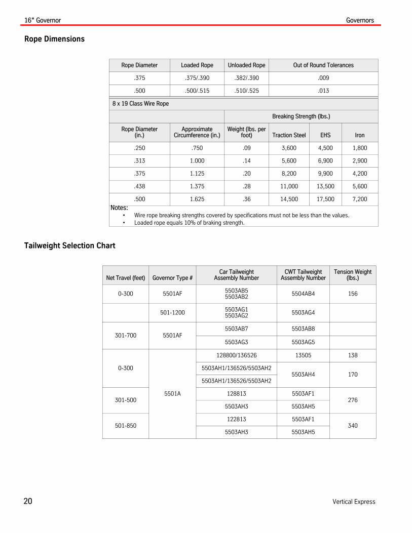
Rope Dimensions
Tailweight Selection Chart
Rope Diameter Loaded Rope Unloaded Rope Out of Round Tolerances
.375 .375/.390 .382/.390 .009
.500 .500/.515 .510/.525 .013
8 x 19 Class Wire Rope
Breaking Strength (lbs.)
Rope Diameter (in.)
Approximate Circumference (in.)
Weight (lbs. per foot) Traction Steel EHS Iron
.250 .750 .09 3,600 4,500 1,800
.313 1.000 .14 5,600 6,900 2,900
.375 1.125 .20 8,200 9,900 4,200
.438 1.375 .28 11,000 13,500 5,600
.500 1.625 .36 14,500 17,500 7,200
Notes:• Wire rope breaking strengths covered by specifications must not be less than the values.• Loaded rope equals 10% of braking strength.
Net Travel (feet) Governor Type #Car Tailweight
Assembly NumberCWT Tailweight
Assembly NumberTension Weight
(lbs.)
0-300 5501AF 5503AB55503AB2 5504AB4 156
501-1200 5503AG15503AG2 5503AG4
301-700 5501AF5503AB7 5503AB8
5503AG3 5503AG5
0-300
5501A
128800/136526 13505 138
5503AH1/136526/5503AH25503AH4 170
5503AH1/136526/5503AH2
301-500128813 5503AF1
2765503AH3 5503AH5
501-850122813 5503AF1
3405503AH3 5503AH5

Governors 16” Governor
Printed in USA June, 2012 21
Installation(continued)
Figure 9 - 16” Governor and Safety System
Shown with jaws set
Trip Plate
NOTE: Reverse assembly of eyebolt toweight and rail bracket if insufficientspace in rear. Iron wire rope must haveslack to allow weight to lift 2“.
Fist Grips
Rope Plate
Fist Grips
Car Detail
To GovernorRope Lever
To GovernorTailweight
Governor Tailweight Sheave
To Governor
Governor Sheave
Jaw GrippingSide
Governor Rope Bracket
Thimble
Lever StopScrew
Hold DownSpring
RopeLever
CarSide
Insert shims as required to level
Stud Rod Turnbuckle
Twin Clevis Link
Draw Bar Spring
Cable 24
Wire Rope Clips
Tie-DownMount Angle
Eye Bolt
MountingPlate
AnchorRope Thimble
Resetting the Governor Jaw
Rail Strap
Iron or Traction Steel Filler Wire RopeFor 12 = 3/8 - 8 x 19For 16 = 1/2 - 8 x 26

16” Governor Installation Governors
22 Vertical Express
16” Governor Installation
Note: The 16” Governor installs the same as the 12” Governor. See 12” Governor Installation on page 10.
Speed Check of Non-Roped Governors
Keep fingers and hands clear of the carrier arm when checking tripping speeds.
1. Chuck the drive wheel device in a 3/8" or 1/2" variable speed drill.
2. Hold a tachometer in place against the groove in the governor sheave. The tachometer should touch the approximate center of the sheave groove. See Table 1 for speed specifications.
3. Place the friction drive wheel against the rim of the governor sheave and slowly increase the speed until the governor switch trips.
Ensure that when the weights fly out, the tachometer is not damaged.
4. Record the switch tripping speed.
5. Continue increasing the governor speed until the governor’s rope jaws trip. Record the jaw tripping speed.
Note: The recorded switch/jaw tripping speeds must comply with those listed in the speed specifications, as mandated by code. See Table 2.
Table 2 - Speed Specifications for 16” Governor
Elevator Rated Speed (FPM)
16 Governor Tripping Speed 16 Tachometer Reading
Switch Jaws Switch Jaws
1300 1398 1560 1354 1511
1400 1505 1440 1458 1628

Governors 16” Governor Installation
Printed in USA June, 2012 23
Tailweight Installation
1. Locate correct installation detail for specific job type. See Figure 10 and Figure 11 on page 24.
2. Verify correct placement of the governor tailweight location. See Figure 12 on page 25.
Figure 10 - Tailweight Installation Details (1 of 2)
128800 (Car)•0-300 ft. of travel•0-500 fpm•12/15# rail
136526•11/12/15/18.5/22.5# rail
5503AH1•501-800 fpm
5503AH2•501-1400 fpm
5503AH6•Variable gov. setting•12/15# rail
5503AH7•18.5/22.5# rail
ITEM PART NO.PRINT NO.DESCRIPTION
1 Tailweight Sheave
2 Weight Strap (Inboard)
3 Weight Strap (Outboard)
4 Dust Cover
5 Extension Arm
6 Rail Clip
3
5
6
1
2
4
16 4
5
130505 (Counterweight)(Tension sheave assembly)•0-300 ft. of travel•0-500 fpm•15/18.5# rail
5503AH4•501-1400 fpm
5503AH8 (Counterweight)•0-300 ft. of travel•501-1400 fpm•Variable gov. setting•30# rail

16” Governor Installation Governors
24 Vertical Express
Tailweight Installation(continued)
Figure 11 - Tailweight Installation Details (2 of 2)
5503AH5 (Counterweight)•301-850 ft. of travel•501-1400 fpm•15# rail
5503AH9•18.5 rail
128813 (Car)•0-500 fpm•11.5” gov. setting•12/15/18.5/22.5# rail
5503AH (Car)•301-850 ft. of travel•501-1400 fpm•15/18.5# rail

Governors 16” Governor Installation
Printed in USA June, 2012 25
Tailweight Locations
Figure 12 - 16” Governor Tailweight Locations
1 5/
8”B
.O.R
.
16” ROPECENTERS
3 3/
16”
B.O
.R.
4” O.A
.
RAILC
10 1
/16”
26 5
/8”
(#12
9028
)30
5/8
” (#
1290
27)
36”
MIN
IMU
M W
ITH
SEI
SM
IC T
IE-D
OW
N A
SS
Y.
1 1/
2”
#129028 = 138##129027 = 170#
4” O.A
.
36”
MIN
IMU
M W
ITH
SEI
SM
IC T
IE-D
OW
NA
SS
Y.
46 5
/8”
(2-#
1290
28) @
276
# TO
TAL
53 5
/8”
(2-#
1290
27) @
340
# TO
TAL
10 1
/16”
16” ROPECENTERS
1 1/
2”B
.O.R
.
RAIL
11 1/2”
C 3 1/
16”
B.O
.R.
1 1/
2”
43 3
/8”
O.A
. BA
R G
UID
E
3 1/
2” (M
IN)
30 1
/4 (M
AX.
)
#129
028
@ 1
38#
OR
#129
027
@ 1
70#
#129
028
@ 1
38#
OR
#129
027
@ 1
70#
18”
18”
18” O.A. 18” O.A.
PIT FLOOR
PIT FLOOR
C C
3/8”
STR
AP
BO
LTPR
OJ.
BEL
OW
3/8”
STR
AP
BO
LTPR
OJ.
BEL
OW
WT.STRAP
WT.STRAP
24# 30#

16” Governor Installation Governors
26 Vertical Express
Tailweight Installation (continued)
3. Choose a position on the rail that provides adequate clearance from the bottom of the tailweight to the pit floor (36" minimum for seismic tie-down), and then mount the rail strap. See Figure 13.
4. Use the nylon thrust washers and any additional connection brackets required to connect the extension arm to the rail strap (corresponding to the model being used).
Note: Ensure that the extension arm pivots freely, and the sheave mounting position lines up with the center of the governor rope loop.
5. Install and adjust the governor rope to ensure that when the rope is in the sheave groove, the extension arm is horizontal or slightly above the rope.
6. Verify the proper weight-to-floor clearance, and also verify that the sheave rotates freely.
7. Install the tie-down assembly, from the weight to the pit floor. See Figure 13.
a. Drill a 1/2" x 2 1/2 hole in the center of the weight for mounting.
b. Before engaging the spring, adjust the assembly to allow for 1" of weight lift.
c. Anchor the tailweight tie-down assembly to the pit floor.
Figure 13 - Tailweight Tie-Down
Drill the required hole for 1/2" x 2 1/2" bolt in the center of the weight.
Anchor to the pit floor.
Adjust to allow for 1" of weight lift before engaging the spring.

Governors Maintenance
Printed in USA June, 2012 27
Speed Check of Roped Governor
Tools and Materials
Figure 14 - Friction Drive Wheel
1. To access the governor, place the elevator on car top inspection operation and locate the car to the top of the hoistway.
2. Block up the governor tailweight sheave in the pit to provide slack in the governor rope.
Notes:
• Governors are calibrated, inspected, and sealed at the factory.
• The governor switch and jaw tripping speeds must be verified during periodic Category 5 testing.
• Switch and jaw tripping speeds are stamped on the governor nameplate.
• Maximum switch and jaw tripping speeds conforming to the rated elevator speed are shown in Table 2 on page 22.
3. As a safety precaution, check all parts thoroughly before placing the elevator in service.
4. At the governor, pull the rope upward until it can be removed from the governor sheave.
5. Use vise grips or "C" clamps, and two (2) pieces of wood to clamp the ropes in place.
6. Check to make sure that the rope is free of kinks.
7. Verify that the rope, when rotated, does not interfere with the sheave.
Maintenance 1. Capture and secure the car at a landing that allows free access to the governor area.
2. Turn OFF, Lock, and Tag out the mainline disconnect.
3. During regularly scheduled maintenance procedures, clean off all dust and dirt from the governor.
4. Examine the ropes for wear, kinks, or misalignment.
5. Signs of side-to-side sheave movement indicate bearing failure and require service or replacement.
Note: The optical disk on the 12” governor must be carefully cleaned. See Encoder Sensor Adjustment on page 12.
4 Diameter RubberDrive Wheel
VariableSpeed Drill
Governor Sheave
TachometerPosition
Rope Pitch Line
• Suitable friction drive wheel
• Variable speed drill
• Tachometer
• "C" clamp or vise grips, and wood blocking
Note: A friction drive wheel can be made. See Figure 14.

MRL Products Governors
28 Vertical Express
MRL Products Note: See the appropriate MRL product manual for additional information.
Overspeed Governor (SG-200)
TrippingSolenoid
Junction Box
A A
4.803.984 .984
.8761.181
.797
2.854
Detail A-A
Nameplate
7.874
16.154
3.937

Governors Overspeed Governor (SG-200)
Printed in USA June, 2012 29
Rope Specifications
Diameter (mm)
SizeMaximum Pull
Force (N)Minimum Tensioning
Force (N)Tension
Pulley Code
6.5 6 x 19 500>300 494 1344.00.02
1344.00.01
1344.00.11
1344.00.15
900>800 812 1344.00.04
1344.00.06
1344.00.07
1344.00.08
1344.00.09
550>300 530 1345.10.02
1345.10.05
1345.15.02
850>800 820 1344.00.10
1344.00.12
1344.00.13
1344.00.16
1344.00.17
1345.10.01
1345.10.04
1345.15.01

12” Self-Resetting Governor (5501AE7) Governors
30 Vertical Express
12” Self-Resetting Governor (5501AE7)
Helical Spring
Rope Retainers
Solenoid Activation
Kit
Remote ResetSwitch Assembly
Rope Grip Carrier
Encoder Cover
Optical Disk
Helical Spring
Rope Retainers
Solenoid Activation
Kit
Remote ResetSwitch Assembly
Rope Grip Carrier
12” Self-Resetting GovernorNon-Digital Counterweight (5501AE5)

Governors Governor Tailweight Assembly
Printed in USA June, 2012 31
Governor Tailweight Assembly 5503AK001, Left Hand
Notes:
• Use with .250 diameter, 8 x 19 rope.
• Mount only to 15# rail.
28.375
9.0008.0009.765
1.729
12.000
2.000
15.812
WeightsSheave Assembly
8” Diameter
Precision Switch
Cam Switch
Tension Weight Switch Bracket
Tension Weight Rail Bracket Assembly

Governor Tailweight Assembly Governors
32 Vertical Express
Governor Tailweight Assembly5503AK101, Right Hand
Notes:
• Use with .250 diameter, 8 x 19 rope.
• Mount only to 15# rail.
Weights
Sheave Assembly 8” Diameter
Precision Switch
Cam Switch Tension Weight
Switch Bracket
Tension Weight Rail Bracket
Assembly
12.000
2.00015.812
28.375
9.000 8.000 9.765
1.729

Governors Governor Kits
Printed in USA June, 2012 33
Governor Kits
Governor Solenoid Kit - 200APJ
• Mounted on the governor frame.
• Connected to the linkage mechanism which is mounted on the rope grip arm.
• Run three (3) 18 AWG conductors from the controller CVR1 terminal strip to the gover-nor activation solenoid junction box. These wires may be run in the same conduit as the governor electrical switch.
Remote Governor Reset Assembly Kit - 200APD
• Mounted on the governor electrical switch box.
• Controlled by the Temperature Fault Reset (TFR) card located in the controller.
• Run a three-conductor 18 AWG shielded cable, TKE print no. 220CW1, between the RGR and the TFR card. This cable may be run in the same conduit as the governor encoder cable.
Remote Governor Reset Assembly Kit – 200APDGovernor Solenoid Kit – 200APJ

Governor Kits Governors
34 Vertical Express
Governor Kits(continued)
Figure 15 - Wiring Diagram for 200APJ/200APD
Jumper to Test
108
GSS2
AC1
AC2
AC2
GSS1
107
108
Controller
GND
GND
0.187Fastons
Gov. SetSolenoid
Governor
GovernorOverspeedSwitch
Safety Circuit
TopFinalLimit
Resettable by the RGR
Tripped by the Governor Trip Solenoid
Jumper to Reset Gov. Switch
GSR2
AC1GSR10.187Fastons
Gov. ResetSolenoid
Governors Replacement Parts
Printed in USA June, 2012 35
Replacement Parts
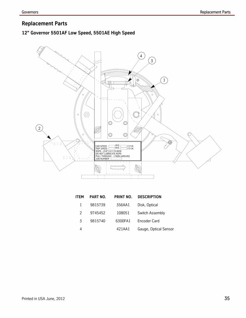
12” Governor 5501AF Low Speed, 5501AE High Speed
ITEM PART NO. PRINT NO. DESCRIPTION
1 9815739 356AA1 Disk, Optical
2 9745452 108051 Switch Assembly
3 9815740 6300FA1 Encoder Card
4 421AA1 Gauge, Optical Sensor
M/SCAR SPEEDTRIP SPEED
JOB NUMBER
DO NOT LUBRICATE ROPEROPE - (3/8”) 8 X 19 IRON
M/SF.P.M.F.P.M.
PULL THROUGH - 1780N (400LBS)
1
2
34

Replacement Parts Governors
36 Vertical Express
12” Tailweight Sheave
ITEM PART NO. PRINT NO. DESCRIPTION
1 9815752 750BH1 Sheave Assembly with Bearings without Liner
2 750BH2 Sheave Assembly with Bearings and Liner
3 200JT1 Tailweight Switch Kit with Cam and Mounting Bracket
1
3
2
1
2
1
2
1
32
1
3
2
5503AB25503AB45503AB105503AG7
5503AB45503AG45503AG
5503AB75503AB95503AG35503AG8
5503AB85503AB125503AG6
5503AB55503AB105503AG2
Governors Replacement Parts
Printed in USA June, 2012 37
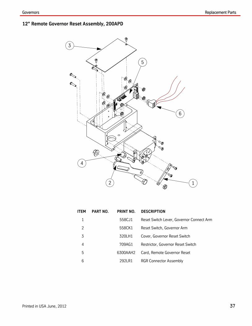
12” Remote Governor Reset Assembly, 200APD
ITEM PART NO. PRINT NO. DESCRIPTION
1 558CJ1 Reset Switch Lever, Governor Connect Arm
2 558CK1 Reset Switch, Governor Arm
3 320LH1 Cover, Governor Reset Switch
4 709AG1 Restrictor, Governor Reset Switch
5 6300AAH2 Card, Remote Governor Reset
6 292LR1 RGR Connector Assembly
6
12
3
4
5
Replacement Parts Governors
38 Vertical Express
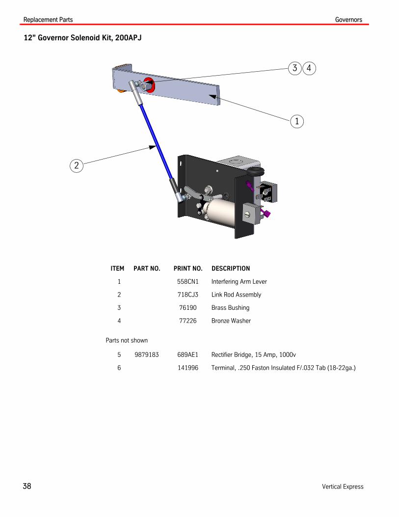
12” Governor Solenoid Kit, 200APJ
ITEM PART NO. PRINT NO. DESCRIPTION
1 558CN1 Interfering Arm Lever
2 718CJ3 Link Rod Assembly
3 76190 Brass Bushing
4 77226 Bronze Washer
Parts not shown
5 9879183 689AE1 Rectifier Bridge, 15 Amp, 1000v
6 141996 Terminal, .250 Faston Insulated F/.032 Tab (18-22ga.)
3 4
1
2

Governors Replacement Parts
Printed in USA June, 2012 39
16” Governor, 5501AA Digital, 5501AB Non-Digital
ITEM PART NO. PRINT NO. DESCRIPTION
1 9745452 108051 Switch Assembly
2 9875261 373AR1 Position Encoder
3 9867553 482AK1 Encoder Housing
4 43949 Shims
5 320BK1 Cover
6 40976 Resetting Bar
7 5502AA Sheave Assembly, (see chart below)
Spring Color/Speed Selection Chart
1
4
6
52 37
Rated Speed FPM Spring Color Part Number
1-200 Red 780AV4
201-400 Orange 780AV2
401-600 Yellow 780AV3
601-1200 Green 780AV1
1201-1400 Blue 780AV5
Replacement Parts Governors
40 Vertical Express
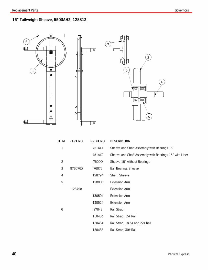
16” Tailweight Sheave, 5503AH3, 128813
ITEM PART NO. PRINT NO. DESCRIPTION
1 751AX1 Sheave and Shaft Assembly with Bearings 16
751AX2 Sheave and Shaft Assembly with Bearings 16” with Liner
2 750DD Sheave 16” without Bearings
3 9760763 76076 Ball Bearing, Sheave
4 128794 Shaft, Sheave
5 128808 Extension Arm
128798 Extension Arm
130504 Extension Arm
130524 Extension Arm
6 27842 Rail Strap
150483 Rail Strap, 15# Rail
150484 Rail Strap, 18.5# and 22# Rail
150485 Rail Strap, 30# Rail
1
6
3
4
5
2
7

Governors Replacement Parts
Printed in USA June, 2012 41
Tailweight Tie-Down Package, 148313
ITEM PART NO. PRINT NO. DESCRIPTION
1 129026 Tie-Down Mount Angle
2 121692 Turnbuckle
3 147964 Twin Clevis Link
4 121693 Draw Bar Spring
5 78025 Cable Clip
6 77434 Rope Thimble
7 120999 Mounting Plate
8 117864 Anchor
2
3
4
5
6
1
87

Replacement Parts Governors
42 Vertical Express
Kits/Assemblies
ITEM PART NO. PRINT NO. DESCRIPTION
1 461CN1 Hanger Assembly, Car Governor
2 461CR1 Hanger Assembly, CWT Governor
3 200BCT__ Kit, 175 FPM for 12” Governor
4 200BCV001 Kit, 175 FPM for 16” Governor
Parts not shown
5 200JT1 Kit, Governor Tailweight Switch
6 200BWT001 Kit, Bolt, Governor Bracket
7 200AMP1 Kit, Fasteners, Governor Stand
1 2
4


Vertical Express
P.O. Box 2019 Memphis, TN 38101 Tel: (866) 448-3789 (toll-free) Fax: (901) 261-1807 www.verticalxpress.comAll illustrations and specifications are based on information in effect at the time of publication approval. Vertical Express reserves the right to changespecification or designs and to discontinue items without prior notification or obligation. v.Y.m. Copyright © 2012 Vertical Express Elevator