Embed Size (px)
Citation preview
Motors I Automation I Energy I Transmission & Distribution I Coatings
N2
CFW501
User’s Manual

N2 User’s Manual
Series: CFW501
Language: English
Document Number: 10002041262 / 00
Publication Date: 09/2013
Contents
CFW501 | 3
CONTENTS
CONTENTS ......................................................................................................................... 3
ABOUT THE MANUAL ....................................................................................................... 5
ABBREVIATIONS AND DEFINITIONS ......................................................................................................... 5 NUMERICAL REPRESENTATION ............................................................................................................... 5 DOCUMENTS ................................................................................................................................................ 5
1 INTRODUCTION TO THE SERIAL COMMUNICATION .............................................. 6
2 INTRODUCTION TO THE N2 COMMUNICATION ...................................................... 7
2.1 N2 MS/TP MESSAGES STRUCTURE .............................................................................................. 7 2.2 COMMANDS AND SUBCOMMANDS .............................................................................................. 7 2.3 POLLING MECHANISM ..................................................................................................................... 8
3 INTERFACE DESCRIPTION ......................................................................................... 9
3.1 PLUG-IN MODULES .......................................................................................................................... 9 3.1.1 Standard plug-in module with two RS485 interfaces (CFW500- CRS485) ........................... 9 3.1.2 Additional plug-in modules ..................................................................................................... 10
3.2 RS485................................................................................................................................................ 10 3.2.1 RS485 Interface Characteristics ............................................................................................ 10 3.2.2 Terminating resistor ................................................................................................................ 10 3.2.3 Indications ................................................................................................................................ 10 3.2.4 Connection with the RS485 Network ..................................................................................... 10
4 PROGRAMMING ........................................................................................................ 11
4.1 SYMBOLS FOR THE PROPERTIES DESCRIPTION ...................................................................... 11 P0105 – 1ST/2ND RAMP SELECTION .......................................................................................................... 11 P0220 – LOCAL/REMOTE SELECTION SOURCE .................................................................................... 11 P0221 – SPEED REFERENCE SELECTION – LOCAL SITUATION ......................................................... 11 P0222 – SPEED REFERENCE SELECTION – REMOTE SITUATION ...................................................... 11 P0223 – FORWARD/REVERSE SELECTION – LOCAL SITUATION ........................................................ 11 P0224 – RUN/STOP SELECTION – LOCAL SITUATION .......................................................................... 11 P0225 – JOG SELECTION – LOCAL SITUATION ..................................................................................... 11 P0226 – FORWARD/REVERSE SELECTION – REMOTE SITUATION .................................................... 11 P0227 – RUN/STOP SELECTION – REMOTE SITUATION ...................................................................... 11 P0228 – JOG SELECTION – REMOTE SITUATION .................................................................................. 11 P0308 – SERIAL ADDRESS ........................................................................................................................ 11 P0310 – SERIAL BAUD RATE .................................................................................................................... 12 P0311 – SERIAL INTERFACE BYTE CONFIGURATION .......................................................................... 12 P0312 – SERIAL PROTOCOL ..................................................................................................................... 13 P0313 – COMMUNICATION ERROR ACTION .......................................................................................... 14 P0314 – SERIAL WATCHDOG ................................................................................................................... 14 P0316 – SERIAL INTERFACE STATUS ..................................................................................................... 15 P0680 – STATUS WORD ............................................................................................................................ 15 P0681 – MOTOR SPEED IN 13 BITS ......................................................................................................... 17 P0682 – SERIAL CONTROL WORD ........................................................................................................... 17 P0683 – SERIAL SPEED REFERENCE ...................................................................................................... 18 P0695 – DIGITAL OUTPUT SETTING ........................................................................................................ 19 P0696 – VALUE 1 FOR ANALOG OUTPUTS ............................................................................................. 20 P0697 – VALUE 2 FOR ANALOG OUTPUTS ............................................................................................. 20 P0698 – VALUE 3 FOR ANALOG OUTPUTS ............................................................................................. 20
5 N2 OBJECTS MODELING .......................................................................................... 21

Contents
CFW501 | 4
5.1 N2 OBJECTS FOR THE CFW501 .................................................................................................... 21 5.1.1 ANALOG INPUT (AI) Object ..................................................................................................... 21 5.1.2 ANALOG OUTPUT (AO) Object ............................................................................................... 21 5.1.3 BINARY INPUT (BI) Object ...................................................................................................... 22 5.1.4 BINARY OUTPUT (BO) Object ................................................................................................ 22 5.1.5 Control System Model DDL .................................................................................................... 23
6 FAULTS AND ALARMS RELATED TO THE N2 COMMUNICATION ........................ 25
A128/F228 – TIMEOUT FOR SERIAL COMMUNICATION ....................................................................... 25
About the Manual
CFW501 | 5
ABOUT THE MANUAL
This manual provides the necessary information for the operation of the CFW501 frequency inverter using the N2 protocol. This manual must be used together with the CFW501 user manual.
ABBREVIATIONS AND DEFINITIONS
ASCII American Standard Code for Information Interchange PLC Programmable Logic Controller HMI Human-Machine Interface ro Read-only rw Read/write
NUMERICAL REPRESENTATION
Decimal numbers are represented by means of digits without suffix. Hexadecimal numbers are represented with the letter ‘h’ after the number.
DOCUMENTS
The N2 protocol for the CFW501 was developed based on the following specifications and documents:
Document Version Source Metasys N2 Specification for Vendors 04-3402-22 REV A Jhonson Controls, Inc

Introduction to the Serial Communication
CFW501 | 6
1 INTRODUCTION TO THE SERIAL COMMUNICATION
In a serial interface, the data bits are sent sequentially through a communication channel, or busbar. Several technologies use serial communication for data transfer, including the RS232 and RS485 interfaces. The standards that specify the RS232 and RS485 interfaces, however, do specify neither the format nor the character sequence for data transmission and reception. In this sense, besides the interface, it is also necessary to identify the protocol used for the communication. The N2 network using the RS485 interface as the physical layer to message exchange. The characteristics of the RS485 serial interface available in the CFW501 frequency inverter, as well as the N2 protocol, will be presented next.
INTRODUCTION TO THE N2 COMMUNICATION
CFW501 | 7
2 INTRODUCTION TO THE N2 COMMUNICATION
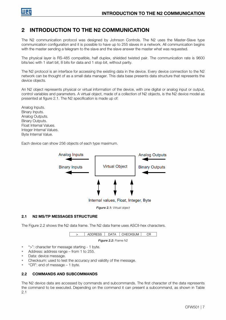
The N2 communication protocol was designed by Johnson Controls. The N2 uses the Master-Slave type communication configuration and it is possible to have up to 255 slaves in a network. All communication begins with the master sending a telegram to the slave and the slave answer the master what was requested. The physical layer is RS-485 compatible, half duplex, shielded twisted pair. The communication rate is 9600 bits/sec with 1 start bit, 8 bits for data and 1 stop bit, without parity. The N2 protocol is an interface for accessing the existing data in the device. Every device connection to the N2 network can be thought of as a small data manager. This data base presents data structure that represents the device objects. An N2 object represents physical or virtual information of the device, with one digital or analog input or output, control variables and parameters. A virtual object, made of a collection of N2 objects, is the N2 device model as presented at figure 2.1. The N2 specification is made up of: Analog Inputs. Binary Inputs. Analog Outputs. Binary Outputs. Float Internal Values. Integer Internal Values. Byte Internal Value. Each device can show 256 objects of each type maximum.
Figure 2.1: Virtual object
2.1 N2 MS/TP MESSAGES STRUCTURE
The Figure 2.2 shows the N2 data frame. The N2 data frame uses ASCII-hex characters.
> ADDRESS DATA CHECKSUM CR
Figure 2.2: Frame N2
“>”: character for message starting - 1 byte. Address: address range – from 1 to 255. Data: device message. Checksum: used to test the accuracy and validity of the message. “CR”: end of message – 1 byte.
2.2 COMMANDS AND SUBCOMMANDS
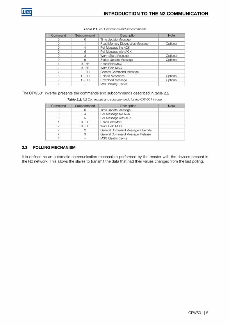
The N2 device data are accessed by commands and subcommands. The first character of the data represents the command to be executed. Depending on the command it can present a subcommand, as shown in Table 2.1
INTRODUCTION TO THE N2 COMMUNICATION
CFW501 | 8
Table 2.1: N2 Commands and subcommands
Command Subcommand Description Note 0 0 Time Update Message 0 1 Read Memory Diagnostics Message Optional 0 4 Poll Message No ACK 0 5 Poll Message with ACK 0 8 Warm Start Message Optional 0 9 Status Update Message Optional 1 0 - FH Read Field MSG 2 0 - FH Write Field MSG 7 0 – FH General Command Message 8 1 – 3H Upload Messages Optional 9 1 – 3H Download Message Optional F - MSG Identify Device
The CFW501 inverter presents the commands and subcommands described in table 2.2
Table 2.2: N2 Commands and subcommands for the CFW501 inverter
Command Subcommand Description Note 0 0 Time Update Message 0 4 Poll Message No ACK 0 5 Poll Message with ACK 1 0 - FH Read Field MSG 2 0 - FH Write Field MSG 7 2 General Command Message: Override 7 3 General Command Message: Release F - MSG Identify Device
2.3 POLLING MECHANISM
It is defined as an automatic communication mechanism performed by the master with the devices present in the N2 network. This allows the slaves to transmit the data that had their values changed from the last polling.
Interface Description
CFW501 | 9
3 INTERFACE DESCRIPTION
The interfaces for serial communication RS485 available for the CFW501 frequency inverter depend on the selected plug-in module for the product. Following are presented information about the connection and installation of the equipment, using different plug-in modules.
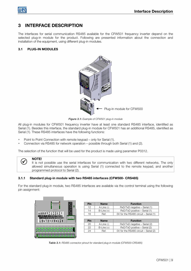
3.1 PLUG-IN MODULES
Figure 3.1: Example of CFW501 plug-in module
All plug-in modules for CFW501 frequency inverter have at least one standard RS485 interface, identified as Serial (1). Besides this interface, the standard plug-in module for CFW501 has an additional RS485, identified as Serial (1). These RS485 interfaces have the following functions: Point to Point Connection with remote keypad – only for Serial (1). Connection via RS485 for network operation – possible through both Serial (1) and (2). The selection of the function that will be used for the product is made using parameter P0312.
NOTE! It is not possible use the serial interfaces for communication with two different networks. The only allowed simultaneous operation is using Serial (1) connected to the remote keypad, and another programmed protocol to Serial (2).
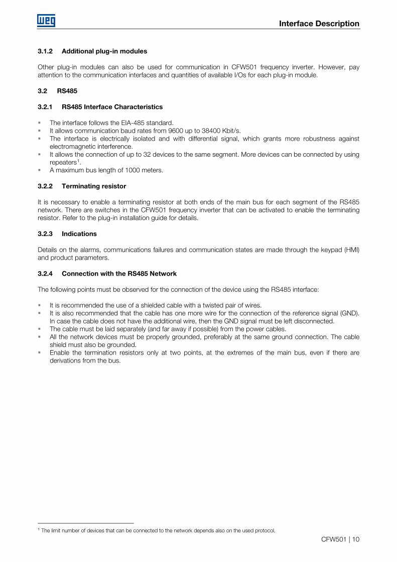
3.1.1 Standard plug-in module with two RS485 interfaces (CFW500- CRS485)
For the standard plug-in module, two RS485 interfaces are available via the control terminal using the following pin assignment:
Pin Name Function 12 A-Line (-) RxD/TxD negative – Serial (1) 14 B-Line (+) RxD/TxD positive – Serial (1) 16 Ref. 0V for the RS485 circuit – Serial (1)
Pin Name Function 20 A-Line (-) RxD/TxD negative – Serial (2) 22 B-Line (+) RxD/TxD positive – Serial (2) 24 Ref. 0V for the RS485 circuit – Serial (2)
Table 3.1: RS485 connector pinout for standard plug-in module (CFW500-CRS485)
Plug-in module for CFW500
Interface Description
CFW501 | 10
3.1.2 Additional plug-in modules
Other plug-in modules can also be used for communication in CFW501 frequency inverter. However, pay attention to the communication interfaces and quantities of available I/Os for each plug-in module.
3.2 RS485
3.2.1 RS485 Interface Characteristics
The interface follows the EIA-485 standard. It allows communication baud rates from 9600 up to 38400 Kbit/s. The interface is electrically isolated and with differential signal, which grants more robustness against
electromagnetic interference. It allows the connection of up to 32 devices to the same segment. More devices can be connected by using
repeaters1. A maximum bus length of 1000 meters.
3.2.2 Terminating resistor
It is necessary to enable a terminating resistor at both ends of the main bus for each segment of the RS485 network. There are switches in the CFW501 frequency inverter that can be activated to enable the terminating resistor. Refer to the plug-in installation guide for details.
3.2.3 Indications
Details on the alarms, communications failures and communication states are made through the keypad (HMI) and product parameters.
3.2.4 Connection with the RS485 Network
The following points must be observed for the connection of the device using the RS485 interface: It is recommended the use of a shielded cable with a twisted pair of wires. It is also recommended that the cable has one more wire for the connection of the reference signal (GND).
In case the cable does not have the additional wire, then the GND signal must be left disconnected. The cable must be laid separately (and far away if possible) from the power cables. All the network devices must be properly grounded, preferably at the same ground connection. The cable
shield must also be grounded. Enable the termination resistors only at two points, at the extremes of the main bus, even if there are
derivations from the bus.
1 The limit number of devices that can be connected to the network depends also on the used protocol.
Programming
CFW501 | 11
4 PROGRAMMING
Next, the CFW501 frequency inverter parameters related to the N2 communication will be presented.
4.1 SYMBOLS FOR THE PROPERTIES DESCRIPTION
RO Reading only parameter CFG Parameter that can be changed only with a stopped motor.
P0105 – 1ST/2ND RAMP SELECTION P0220 – LOCAL/REMOTE SELECTION SOURCE P0221 – SPEED REFERENCE SELECTION – LOCAL SITUATION P0222 – SPEED REFERENCE SELECTION – REMOTE SITUATION P0223 – FORWARD/REVERSE SELECTION – LOCAL SITUATION P0224 – RUN/STOP SELECTION – LOCAL SITUATION P0225 – JOG SELECTION – LOCAL SITUATION P0226 – FORWARD/REVERSE SELECTION – REMOTE SITUATION P0227 – RUN/STOP SELECTION – REMOTE SITUATION P0228 – JOG SELECTION – REMOTE SITUATION These parameters are used in the configuration of the command source for the CFW501 frequency inverter local and remote situations. In order that the device be controlled through the N2 interface, the options ‘serial’ available in these parameters, must be selected. The detailed description of these parameters is found in the CFW501 programming manual. P0308 – SERIAL ADDRESS Range: 0 to 255 Default: 1 Properties: CFG Access groups via HMI: NET Description: It allows programming the address used for the inverter serial communication. It is necessary that each device in the network has an address different from all the others. The valid addresses for this parameter depend on the protocol programmed in P0312: HMI → programming needn’t address. Modbus RTU → valid addresses: 1 to 247. BACnet → valid addresses: 0 to 254. N2 → valid addresses: 1 to 255.
Programming
CFW501 | 12
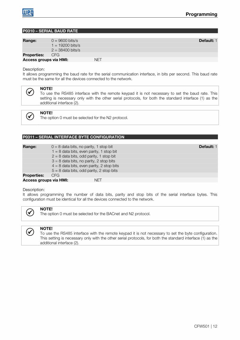
P0310 – SERIAL BAUD RATE Range: 0 = 9600 bits/s Default: 1 1 = 19200 bits/s 2 = 38400 bits/s Properties: CFG Access groups via HMI: NET Description: It allows programming the baud rate for the serial communication interface, in bits per second. This baud rate must be the same for all the devices connected to the network.
NOTE! To use the RS485 interface with the remote keypad it is not necessary to set the baud rate. This setting is necessary only with the other serial protocols, for both the standard interface (1) as the additional interface (2).
NOTE! The option 0 must be selected for the N2 protocol.
P0311 – SERIAL INTERFACE BYTE CONFIGURATION Range: 0 = 8 data bits, no parity, 1 stop bit Default: 1 1 = 8 data bits, even parity, 1 stop bit 2 = 8 data bits, odd parity, 1 stop bit 3 = 8 data bits, no parity, 2 stop bits 4 = 8 data bits, even parity, 2 stop bits 5 = 8 data bits, odd parity, 2 stop bits Properties: CFG Access groups via HMI: NET Description: It allows programming the number of data bits, parity and stop bits of the serial interface bytes. This configuration must be identical for all the devices connected to the network.
NOTE! The option 0 must be selected for the BACnet and N2 protocol.
NOTE! To use the RS485 interface with the remote keypad it is not necessary to set the byte configuration. This setting is necessary only with the other serial protocols, for both the standard interface (1) as the additional interface (2).
Programming
CFW501 | 13
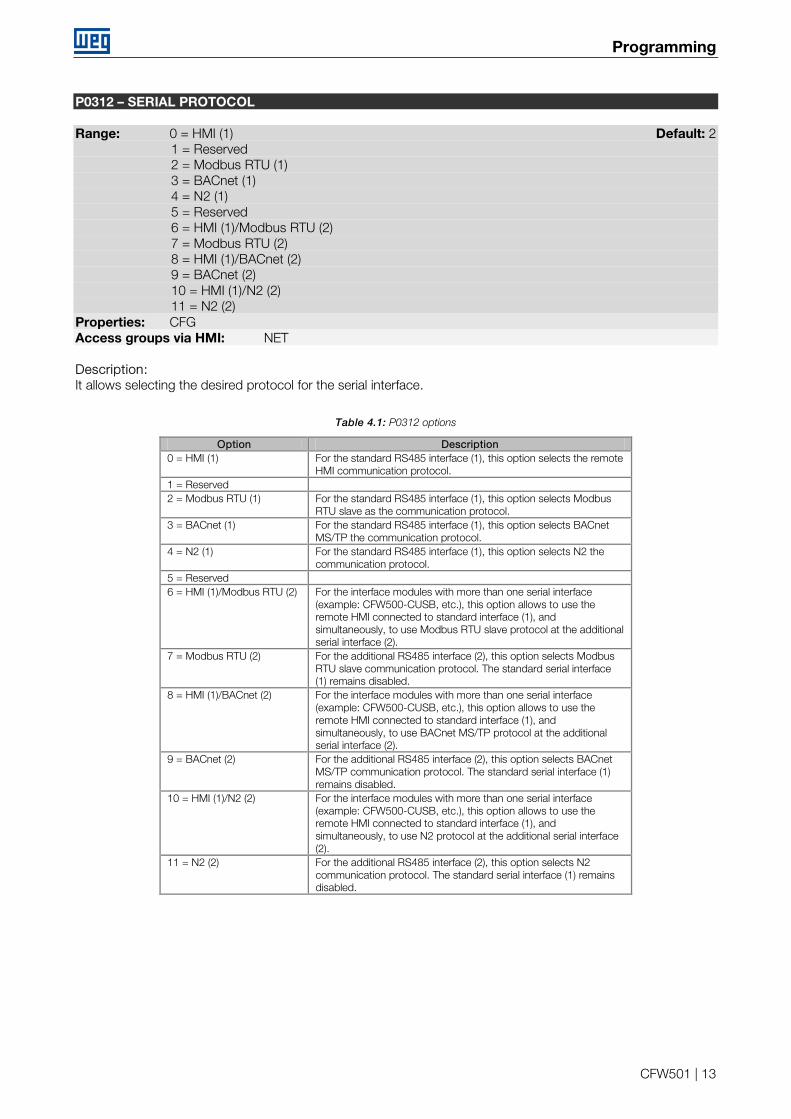
P0312 – SERIAL PROTOCOL Range: 0 = HMI (1) Default: 2 1 = Reserved 2 = Modbus RTU (1) 3 = BACnet (1) 4 = N2 (1) 5 = Reserved 6 = HMI (1)/Modbus RTU (2) 7 = Modbus RTU (2) 8 = HMI (1)/BACnet (2) 9 = BACnet (2) 10 = HMI (1)/N2 (2) 11 = N2 (2) Properties: CFG Access groups via HMI: NET Description: It allows selecting the desired protocol for the serial interface.
Table 4.1: P0312 options
Option Description 0 = HMI (1) For the standard RS485 interface (1), this option selects the remote
HMI communication protocol. 1 = Reserved 2 = Modbus RTU (1) For the standard RS485 interface (1), this option selects Modbus
RTU slave as the communication protocol. 3 = BACnet (1) For the standard RS485 interface (1), this option selects BACnet
MS/TP the communication protocol. 4 = N2 (1) For the standard RS485 interface (1), this option selects N2 the
communication protocol. 5 = Reserved 6 = HMI (1)/Modbus RTU (2) For the interface modules with more than one serial interface
(example: CFW500-CUSB, etc.), this option allows to use the remote HMI connected to standard interface (1), and simultaneously, to use Modbus RTU slave protocol at the additional serial interface (2).
7 = Modbus RTU (2) For the additional RS485 interface (2), this option selects Modbus RTU slave communication protocol. The standard serial interface (1) remains disabled.
8 = HMI (1)/BACnet (2) For the interface modules with more than one serial interface (example: CFW500-CUSB, etc.), this option allows to use the remote HMI connected to standard interface (1), and simultaneously, to use BACnet MS/TP protocol at the additional serial interface (2).
9 = BACnet (2) For the additional RS485 interface (2), this option selects BACnet MS/TP communication protocol. The standard serial interface (1) remains disabled.
10 = HMI (1)/N2 (2) For the interface modules with more than one serial interface (example: CFW500-CUSB, etc.), this option allows to use the remote HMI connected to standard interface (1), and simultaneously, to use N2 protocol at the additional serial interface (2).
11 = N2 (2) For the additional RS485 interface (2), this option selects N2 communication protocol. The standard serial interface (1) remains disabled.
Programming
CFW501 | 14
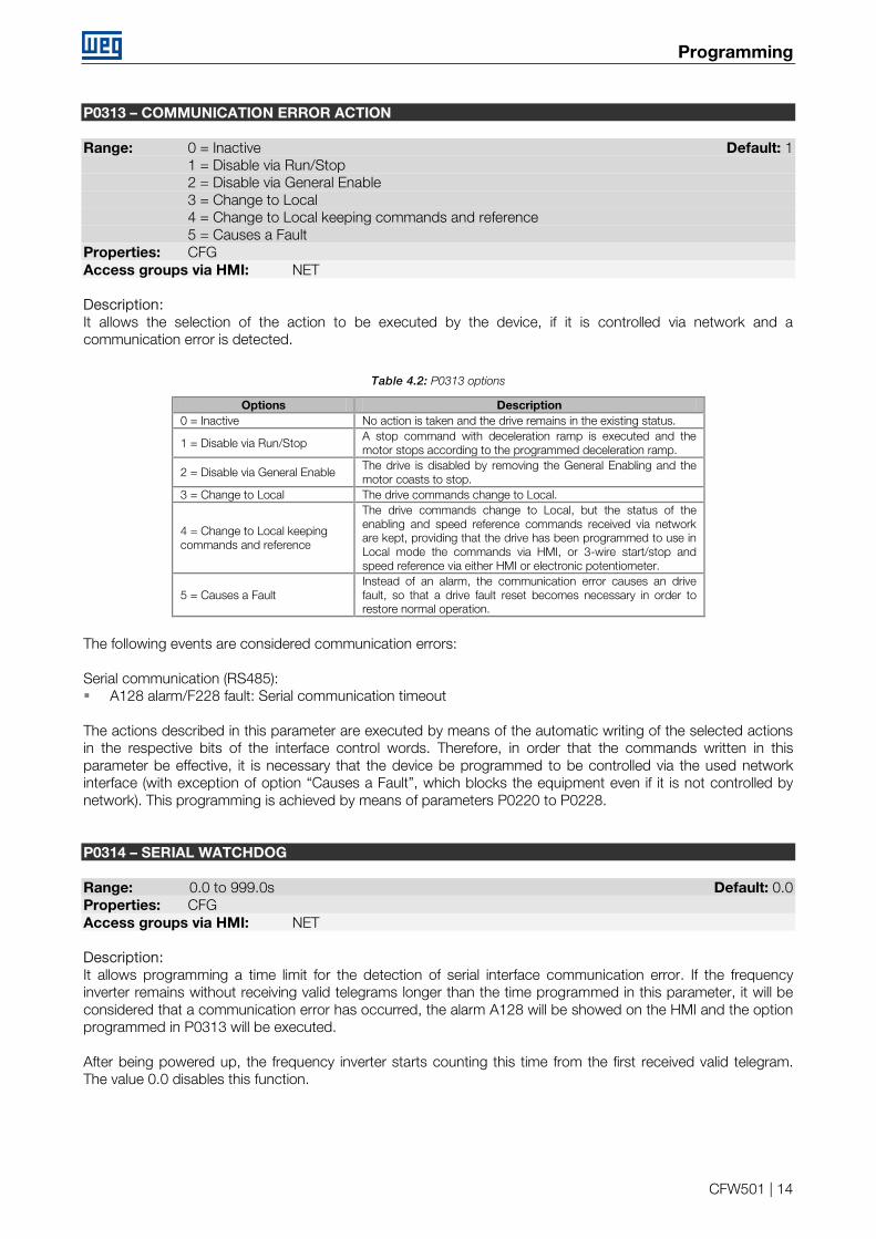
P0313 – COMMUNICATION ERROR ACTION Range: 0 = Inactive Default: 1 1 = Disable via Run/Stop 2 = Disable via General Enable 3 = Change to Local 4 = Change to Local keeping commands and reference 5 = Causes a Fault Properties: CFG Access groups via HMI: NET Description: It allows the selection of the action to be executed by the device, if it is controlled via network and a communication error is detected.
Table 4.2: P0313 options
Options Description 0 = Inactive No action is taken and the drive remains in the existing status.
1 = Disable via Run/Stop A stop command with deceleration ramp is executed and the motor stops according to the programmed deceleration ramp.
2 = Disable via General Enable The drive is disabled by removing the General Enabling and the motor coasts to stop.
3 = Change to Local The drive commands change to Local.
4 = Change to Local keeping commands and reference
The drive commands change to Local, but the status of the enabling and speed reference commands received via network are kept, providing that the drive has been programmed to use in Local mode the commands via HMI, or 3-wire start/stop and speed reference via either HMI or electronic potentiometer.
5 = Causes a Fault Instead of an alarm, the communication error causes an drive fault, so that a drive fault reset becomes necessary in order to restore normal operation.
The following events are considered communication errors: Serial communication (RS485): A128 alarm/F228 fault: Serial communication timeout The actions described in this parameter are executed by means of the automatic writing of the selected actions in the respective bits of the interface control words. Therefore, in order that the commands written in this parameter be effective, it is necessary that the device be programmed to be controlled via the used network interface (with exception of option “Causes a Fault”, which blocks the equipment even if it is not controlled by network). This programming is achieved by means of parameters P0220 to P0228. P0314 – SERIAL WATCHDOG Range: 0.0 to 999.0s Default: 0.0 Properties: CFG Access groups via HMI: NET Description: It allows programming a time limit for the detection of serial interface communication error. If the frequency inverter remains without receiving valid telegrams longer than the time programmed in this parameter, it will be considered that a communication error has occurred, the alarm A128 will be showed on the HMI and the option programmed in P0313 will be executed. After being powered up, the frequency inverter starts counting this time from the first received valid telegram. The value 0.0 disables this function.
Programming
CFW501 | 15
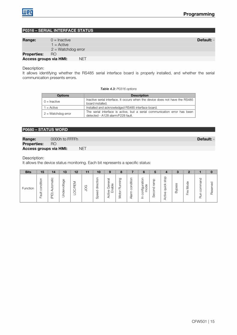
P0316 – SERIAL INTERFACE STATUS Range: 0 = Inactive Default: - 1 = Active 2 = Watchdog error Properties: RO Access groups via HMI: NET Description: It allows identifying whether the RS485 serial interface board is properly installed, and whether the serial communication presents errors.
Table 4.3: P0316 options
Options Description
0 = Inactive Inactive serial interface. It occurs when the device does not have the RS485 board installed.
1 = Active Installed and acknowledged RS485 interface board.
2 = Watchdog error The serial interface is active, but a serial communication error has been detected - A128 alarm/F228 fault.
P0680 – STATUS WORD Range: 0000h to FFFFh Default: - Properties: RO Access groups via HMI: NET Description: It allows the device status monitoring. Each bit represents a specific status:
Bits 15 14 13 12 11 10 9 8 7 6 5 4 3 2 1 0
Function
Faul
t con
ditio
n
(PID
) Aut
omat
ic
Und
ervo
ltage
LOC
/RE
M
JOG
Spe
ed d
irect
ion
Act
ive
Gen
eral
E
nabl
e
Mot
or R
unni
ng
Ala
rm c
ondi
tion
In c
onfig
urat
ion
mod
e
Sec
ond
ram
p
Act
ive
quic
k st
op
Byp
ass
Fire
Mod
e
Run
com
man
d
Res
erve
d
Programming
CFW501 | 16
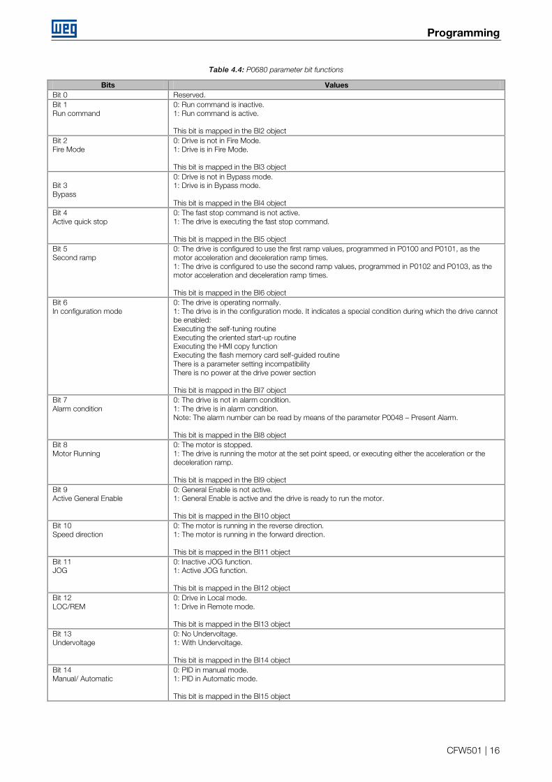
Table 4.4: P0680 parameter bit functions
Bits Values Bit 0 Reserved. Bit 1 Run command
0: Run command is inactive. 1: Run command is active. This bit is mapped in the BI2 object
Bit 2 Fire Mode
0: Drive is not in Fire Mode. 1: Drive is in Fire Mode. This bit is mapped in the BI3 object
Bit 3 Bypass
0: Drive is not in Bypass mode. 1: Drive is in Bypass mode. This bit is mapped in the BI4 object
Bit 4 Active quick stop
0: The fast stop command is not active. 1: The drive is executing the fast stop command. This bit is mapped in the BI5 object
Bit 5 Second ramp
0: The drive is configured to use the first ramp values, programmed in P0100 and P0101, as the motor acceleration and deceleration ramp times. 1: The drive is configured to use the second ramp values, programmed in P0102 and P0103, as the motor acceleration and deceleration ramp times. This bit is mapped in the BI6 object
Bit 6 In configuration mode
0: The drive is operating normally. 1: The drive is in the configuration mode. It indicates a special condition during which the drive cannot be enabled: Executing the self-tuning routine Executing the oriented start-up routine Executing the HMI copy function Executing the flash memory card self-guided routine There is a parameter setting incompatibility There is no power at the drive power section This bit is mapped in the BI7 object
Bit 7 Alarm condition
0: The drive is not in alarm condition. 1: The drive is in alarm condition. Note: The alarm number can be read by means of the parameter P0048 – Present Alarm. This bit is mapped in the BI8 object
Bit 8 Motor Running
0: The motor is stopped. 1: The drive is running the motor at the set point speed, or executing either the acceleration or the deceleration ramp. This bit is mapped in the BI9 object
Bit 9 Active General Enable
0: General Enable is not active. 1: General Enable is active and the drive is ready to run the motor. This bit is mapped in the BI10 object
Bit 10 Speed direction
0: The motor is running in the reverse direction. 1: The motor is running in the forward direction. This bit is mapped in the BI11 object
Bit 11 JOG
0: Inactive JOG function. 1: Active JOG function. This bit is mapped in the BI12 object
Bit 12 LOC/REM
0: Drive in Local mode. 1: Drive in Remote mode. This bit is mapped in the BI13 object
Bit 13 Undervoltage
0: No Undervoltage. 1: With Undervoltage. This bit is mapped in the BI14 object
Bit 14 Manual/ Automatic
0: PID in manual mode. 1: PID in Automatic mode. This bit is mapped in the BI15 object
Programming
CFW501 | 17
Bit 15 Fault condition
0: The drive is not in a fault condition. 1: The drive has detected a fault. Note: The fault number can be read by means of the parameter P0049 – Present Fault. This bit is mapped in the BI16 object
P0681 – MOTOR SPEED IN 13 BITS Range: - 32768 to 32767 Default: - Properties: RO Access groups via HMI: NET Description: It allows monitoring the motor speed. This word uses 13-bit resolution with signal to represent the motor synchronous speed: P0681 = 0000h (0 decimal) → motor speed = 0 P0681 = 2000h (8192 decimal) → motor speed = synchronous speed Intermediate or higher speed values in rpm can be obtained by using this scale. E.g. for a 4 pole motor and 1800 rpm of synchronous speed if the value read is 2048 (0800h), then, to obtain the speed in rpm one must calculate:
8192 => 1800 rpm 2048 => Speed in rpm
Speed in rpm = 1800 × 2048 8192
Speed in rpm = 450 rpm
Negative values in this parameter indicate that the motor is running in the reverse direction. This parameter is mapped in the AI18 object. P0682 – SERIAL CONTROL WORD Range: 0000h to FFFFh Default: 0000h Properties: - Access groups via HMI: NET Description: It is the device N2 interface control word. This parameter can only be changed via serial interface. For the other sources (HMI, etc.) it behaves like a read-only parameter. In order to have those commands executed, it is necessary to program the equipment to be controlled via serial. This programming is achieved by means of parameters P0105 and P0220 to P0228. Each bit of this word represents a command that can be executed.
Bits 15 14 13 13 to 8 7 6 5 4 3 2 1 0
Function
Res
erve
d
Ext
erna
l PID
co
ntro
ller
1
Mai
n P
ID c
ontr
olle
r
Res
erve
d
Faul
t res
et
Qui
ck s
top
Sec
ond
ram
p
LOC
/RE
M
JOG
Spe
ed d
irect
ion
Gen
eral
ena
ble
Run
/Sto
p
Programming
CFW501 | 18
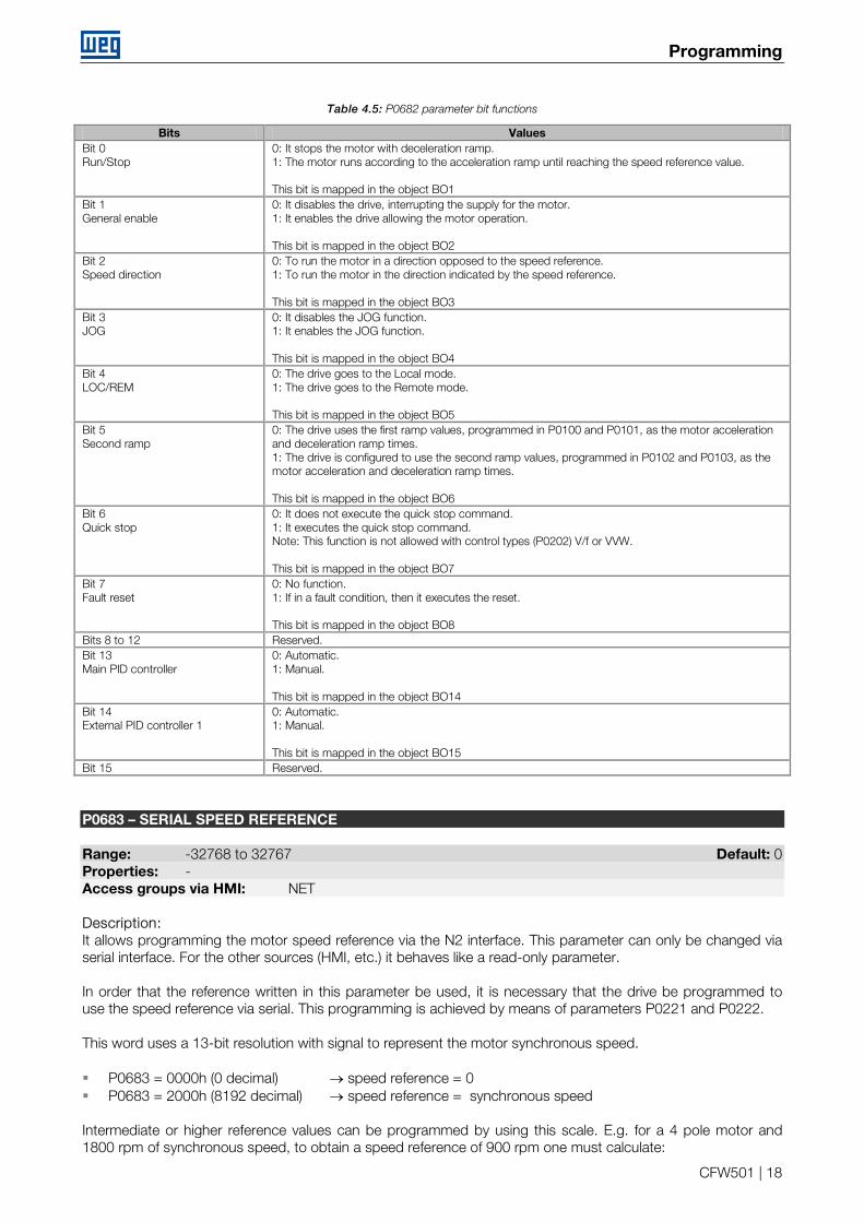
Table 4.5: P0682 parameter bit functions
Bits Values Bit 0 Run/Stop
0: It stops the motor with deceleration ramp. 1: The motor runs according to the acceleration ramp until reaching the speed reference value. This bit is mapped in the object BO1
Bit 1 General enable
0: It disables the drive, interrupting the supply for the motor. 1: It enables the drive allowing the motor operation. This bit is mapped in the object BO2
Bit 2 Speed direction
0: To run the motor in a direction opposed to the speed reference. 1: To run the motor in the direction indicated by the speed reference. This bit is mapped in the object BO3
Bit 3 JOG
0: It disables the JOG function. 1: It enables the JOG function. This bit is mapped in the object BO4
Bit 4 LOC/REM
0: The drive goes to the Local mode. 1: The drive goes to the Remote mode. This bit is mapped in the object BO5
Bit 5 Second ramp
0: The drive uses the first ramp values, programmed in P0100 and P0101, as the motor acceleration and deceleration ramp times. 1: The drive is configured to use the second ramp values, programmed in P0102 and P0103, as the motor acceleration and deceleration ramp times. This bit is mapped in the object BO6
Bit 6 Quick stop
0: It does not execute the quick stop command. 1: It executes the quick stop command. Note: This function is not allowed with control types (P0202) V/f or VVW. This bit is mapped in the object BO7
Bit 7 Fault reset
0: No function. 1: If in a fault condition, then it executes the reset. This bit is mapped in the object BO8
Bits 8 to 12 Reserved. Bit 13 Main PID controller
0: Automatic. 1: Manual. This bit is mapped in the object BO14
Bit 14 External PID controller 1
0: Automatic. 1: Manual. This bit is mapped in the object BO15
Bit 15 Reserved.
P0683 – SERIAL SPEED REFERENCE Range: -32768 to 32767 Default: 0 Properties: - Access groups via HMI: NET Description: It allows programming the motor speed reference via the N2 interface. This parameter can only be changed via serial interface. For the other sources (HMI, etc.) it behaves like a read-only parameter. In order that the reference written in this parameter be used, it is necessary that the drive be programmed to use the speed reference via serial. This programming is achieved by means of parameters P0221 and P0222. This word uses a 13-bit resolution with signal to represent the motor synchronous speed. P0683 = 0000h (0 decimal) → speed reference = 0 P0683 = 2000h (8192 decimal) → speed reference = synchronous speed Intermediate or higher reference values can be programmed by using this scale. E.g. for a 4 pole motor and 1800 rpm of synchronous speed, to obtain a speed reference of 900 rpm one must calculate:
Programming
CFW501 | 19
1800 rpm => 8192 900 rpm => 13 bit reference
13 bit reference = 900 × 8192 1800
13 bit reference = 4096
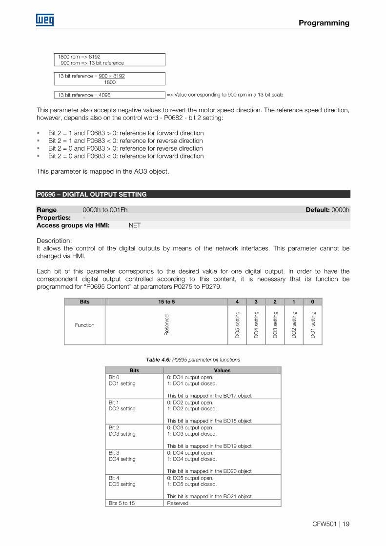
This parameter also accepts negative values to revert the motor speed direction. The reference speed direction, however, depends also on the control word - P0682 - bit 2 setting: Bit 2 = 1 and P0683 > 0: reference for forward direction Bit 2 = 1 and P0683 < 0: reference for reverse direction Bit 2 = 0 and P0683 > 0: reference for reverse direction Bit 2 = 0 and P0683 < 0: reference for forward direction This parameter is mapped in the AO3 object. P0695 – DIGITAL OUTPUT SETTING Range 0000h to 001Fh Default: 0000h Properties: - Access groups via HMI: NET Description: It allows the control of the digital outputs by means of the network interfaces. This parameter cannot be changed via HMI. Each bit of this parameter corresponds to the desired value for one digital output. In order to have the correspondent digital output controlled according to this content, it is necessary that its function be programmed for “P0695 Content” at parameters P0275 to P0279.
Bits 15 to 5 4 3 2 1 0
Function
Res
erve
d
DO
5 se
ttin
g
DO
4 se
ttin
g
DO
3 se
ttin
g
DO
2 se
ttin
g
DO
1 se
ttin
g
Table 4.6: P0695 parameter bit functions
Bits Values Bit 0 DO1 setting
0: DO1 output open. 1: DO1 output closed. This bit is mapped in the BO17 object
Bit 1 DO2 setting
0: DO2 output open. 1: DO2 output closed. This bit is mapped in the BO18 object
Bit 2 DO3 setting
0: DO3 output open. 1: DO3 output closed. This bit is mapped in the BO19 object
Bit 3 DO4 setting
0: DO4 output open. 1: DO4 output closed. This bit is mapped in the BO20 object
Bit 4 DO5 setting
0: DO5 output open. 1: DO5 output closed. This bit is mapped in the BO21 object
Bits 5 to 15 Reserved
=> Value corresponding to 900 rpm in a 13 bit scale
Programming
CFW501 | 20
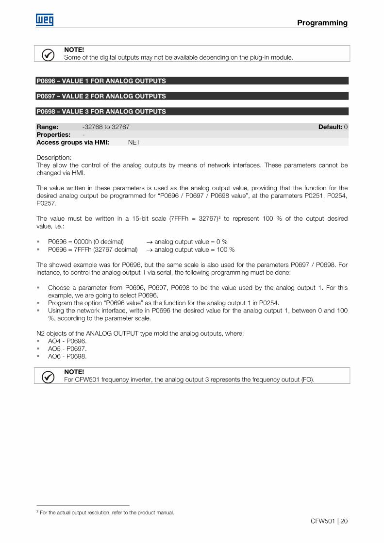
NOTE! Some of the digital outputs may not be available depending on the plug-in module.
P0696 – VALUE 1 FOR ANALOG OUTPUTS P0697 – VALUE 2 FOR ANALOG OUTPUTS P0698 – VALUE 3 FOR ANALOG OUTPUTS Range: -32768 to 32767 Default: 0 Properties: - Access groups via HMI: NET Description: They allow the control of the analog outputs by means of network interfaces. These parameters cannot be changed via HMI. The value written in these parameters is used as the analog output value, providing that the function for the desired analog output be programmed for “P0696 / P0697 / P0698 value”, at the parameters P0251, P0254, P0257. The value must be written in a 15-bit scale (7FFFh = 32767)2 to represent 100 % of the output desired value, i.e.: P0696 = 0000h (0 decimal) → analog output value = 0 % P0696 = 7FFFh (32767 decimal) → analog output value = 100 % The showed example was for P0696, but the same scale is also used for the parameters P0697 / P0698. For instance, to control the analog output 1 via serial, the following programming must be done: Choose a parameter from P0696, P0697, P0698 to be the value used by the analog output 1. For this
example, we are going to select P0696. Program the option “P0696 value” as the function for the analog output 1 in P0254. Using the network interface, write in P0696 the desired value for the analog output 1, between 0 and 100
%, according to the parameter scale. N2 objects of the ANALOG OUTPUT type mold the analog outputs, where: AO4 - P0696. AO5 - P0697. AO6 - P0698.
NOTE! For CFW501 frequency inverter, the analog output 3 represents the frequency output (FO).
2 For the actual output resolution, refer to the product manual.
n2 objects modeling
CFW501 | 21
5 N2 OBJECTS MODELING
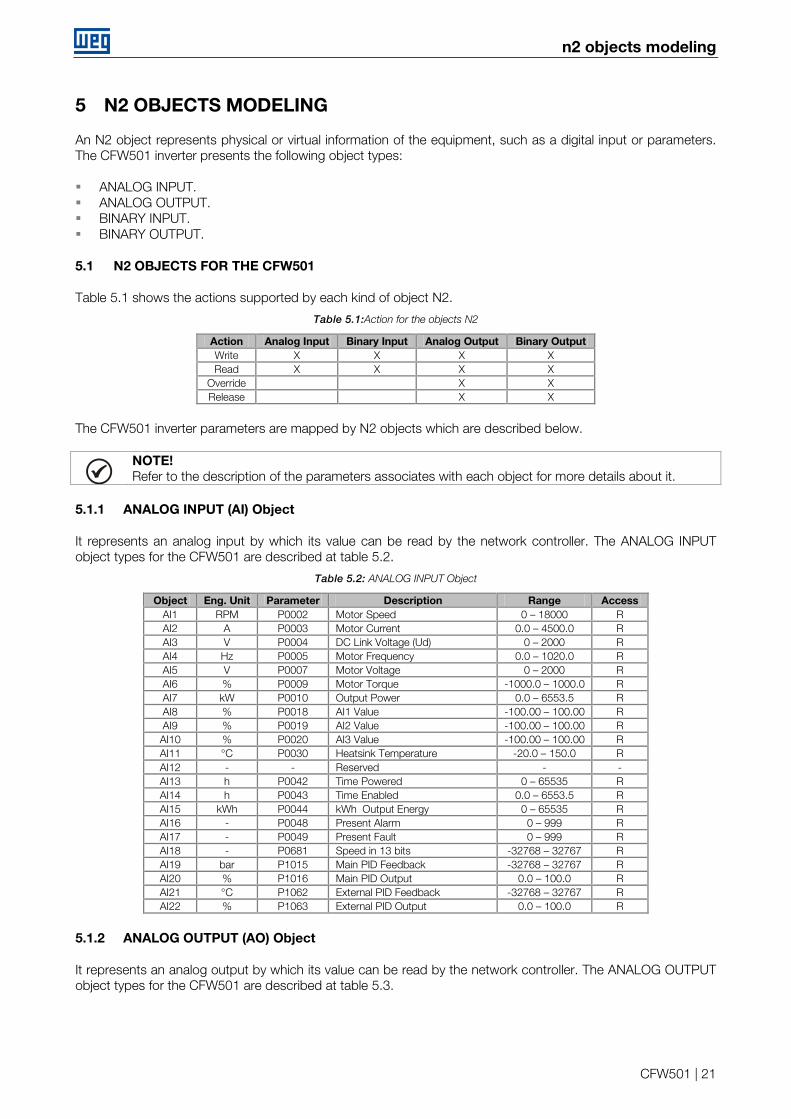
An N2 object represents physical or virtual information of the equipment, such as a digital input or parameters. The CFW501 inverter presents the following object types: ANALOG INPUT. ANALOG OUTPUT. BINARY INPUT. BINARY OUTPUT.
5.1 N2 OBJECTS FOR THE CFW501
Table 5.1 shows the actions supported by each kind of object N2.
Table 5.1:Action for the objects N2
Action Analog Input Binary Input Analog Output Binary Output Write X X X X Read X X X X
Override X X Release X X
The CFW501 inverter parameters are mapped by N2 objects which are described below.
NOTE! Refer to the description of the parameters associates with each object for more details about it.
5.1.1 ANALOG INPUT (AI) Object
It represents an analog input by which its value can be read by the network controller. The ANALOG INPUT object types for the CFW501 are described at table 5.2.
Table 5.2: ANALOG INPUT Object
Object Eng. Unit Parameter Description Range Access AI1 RPM P0002 Motor Speed 0 – 18000 R AI2 A P0003 Motor Current 0.0 – 4500.0 R AI3 V P0004 DC Link Voltage (Ud) 0 – 2000 R AI4 Hz P0005 Motor Frequency 0.0 – 1020.0 R AI5 V P0007 Motor Voltage 0 – 2000 R AI6 % P0009 Motor Torque -1000.0 – 1000.0 R AI7 kW P0010 Output Power 0.0 – 6553.5 R AI8 % P0018 AI1 Value -100.00 – 100.00 R AI9 % P0019 AI2 Value -100.00 – 100.00 R AI10 % P0020 AI3 Value -100.00 – 100.00 R AI11 °C P0030 Heatsink Temperature -20.0 – 150.0 R AI12 - - Reserved - - AI13 h P0042 Time Powered 0 – 65535 R AI14 h P0043 Time Enabled 0.0 – 6553.5 R AI15 kWh P0044 kWh Output Energy 0 – 65535 R AI16 - P0048 Present Alarm 0 – 999 R AI17 - P0049 Present Fault 0 – 999 R AI18 - P0681 Speed in 13 bits -32768 – 32767 R AI19 bar P1015 Main PID Feedback -32768 – 32767 R AI20 % P1016 Main PID Output 0.0 – 100.0 R AI21 °C P1062 External PID Feedback -32768 – 32767 R AI22 % P1063 External PID Output 0.0 – 100.0 R
5.1.2 ANALOG OUTPUT (AO) Object
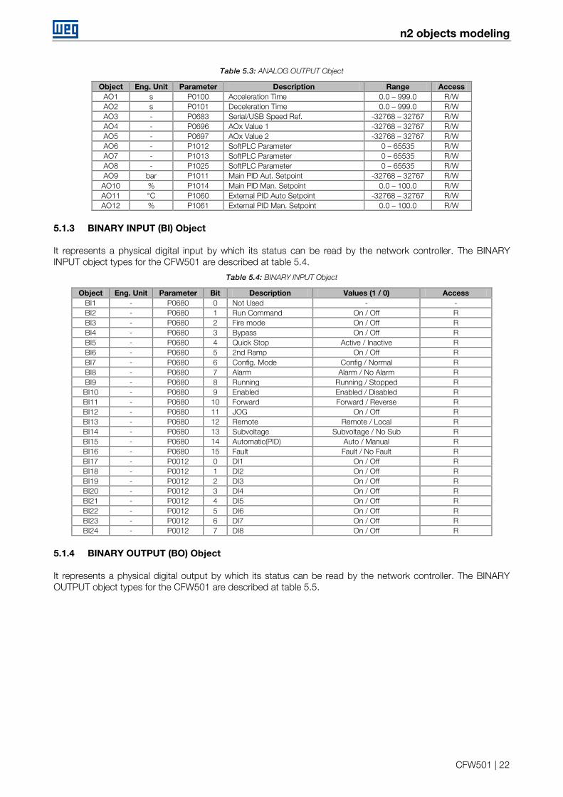
It represents an analog output by which its value can be read by the network controller. The ANALOG OUTPUT object types for the CFW501 are described at table 5.3.
n2 objects modeling
CFW501 | 22
Table 5.3: ANALOG OUTPUT Object
Object Eng. Unit Parameter Description Range Access AO1 s P0100 Acceleration Time 0.0 – 999.0 R/W AO2 s P0101 Deceleration Time 0.0 – 999.0 R/W AO3 - P0683 Serial/USB Speed Ref. -32768 – 32767 R/W AO4 - P0696 AOx Value 1 -32768 – 32767 R/W AO5 - P0697 AOx Value 2 -32768 – 32767 R/W AO6 - P1012 SoftPLC Parameter 0 – 65535 R/W AO7 - P1013 SoftPLC Parameter 0 – 65535 R/W AO8 - P1025 SoftPLC Parameter 0 – 65535 R/W AO9 bar P1011 Main PID Aut. Setpoint -32768 – 32767 R/W
AO10 % P1014 Main PID Man. Setpoint 0.0 – 100.0 R/W AO11 °C P1060 External PID Auto Setpoint -32768 – 32767 R/W AO12 % P1061 External PID Man. Setpoint 0.0 – 100.0 R/W
5.1.3 BINARY INPUT (BI) Object
It represents a physical digital input by which its status can be read by the network controller. The BINARY INPUT object types for the CFW501 are described at table 5.4.
Table 5.4: BINARY INPUT Object
Object Eng. Unit Parameter Bit Description Values (1 / 0) Access BI1 - P0680 0 Not Used - - BI2 - P0680 1 Run Command On / Off R BI3 - P0680 2 Fire mode On / Off R BI4 - P0680 3 Bypass On / Off R BI5 - P0680 4 Quick Stop Active / Inactive R BI6 - P0680 5 2nd Ramp On / Off R BI7 - P0680 6 Config. Mode Config / Normal R BI8 - P0680 7 Alarm Alarm / No Alarm R BI9 - P0680 8 Running Running / Stopped R BI10 - P0680 9 Enabled Enabled / Disabled R BI11 - P0680 10 Forward Forward / Reverse R BI12 - P0680 11 JOG On / Off R BI13 - P0680 12 Remote Remote / Local R BI14 - P0680 13 Subvoltage Subvoltage / No Sub R BI15 - P0680 14 Automatic(PID) Auto / Manual R BI16 - P0680 15 Fault Fault / No Fault R BI17 - P0012 0 DI1 On / Off R BI18 - P0012 1 DI2 On / Off R BI19 - P0012 2 DI3 On / Off R BI20 - P0012 3 DI4 On / Off R BI21 - P0012 4 DI5 On / Off R BI22 - P0012 5 DI6 On / Off R BI23 - P0012 6 DI7 On / Off R BI24 - P0012 7 DI8 On / Off R
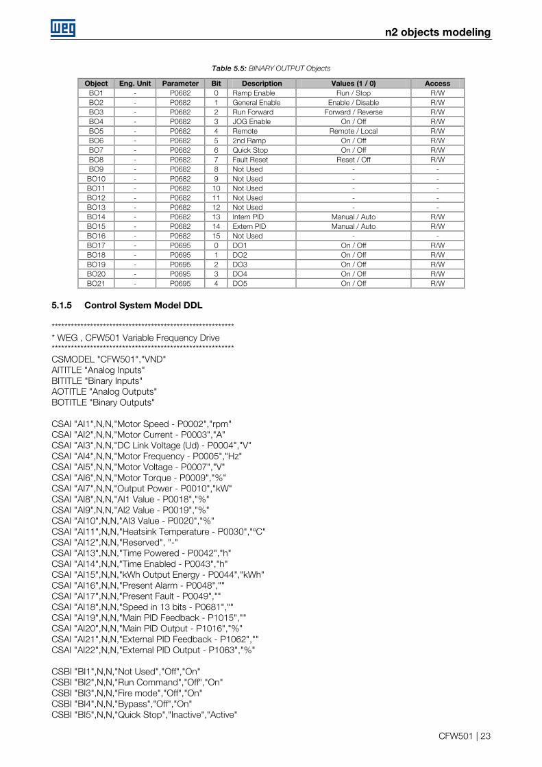
5.1.4 BINARY OUTPUT (BO) Object
It represents a physical digital output by which its status can be read by the network controller. The BINARY OUTPUT object types for the CFW501 are described at table 5.5.
n2 objects modeling
CFW501 | 23
Table 5.5: BINARY OUTPUT Objects
Object Eng. Unit Parameter Bit Description Values (1 / 0) Access BO1 - P0682 0 Ramp Enable Run / Stop R/W BO2 - P0682 1 General Enable Enable / Disable R/W BO3 - P0682 2 Run Forward Forward / Reverse R/W BO4 - P0682 3 JOG Enable On / Off R/W BO5 - P0682 4 Remote Remote / Local R/W BO6 - P0682 5 2nd Ramp On / Off R/W BO7 - P0682 6 Quick Stop On / Off R/W BO8 - P0682 7 Fault Reset Reset / Off R/W BO9 - P0682 8 Not Used - -
BO10 - P0682 9 Not Used - - BO11 - P0682 10 Not Used - - BO12 - P0682 11 Not Used - - BO13 - P0682 12 Not Used - - BO14 - P0682 13 Intern PID Manual / Auto R/W BO15 - P0682 14 Extern PID Manual / Auto R/W BO16 - P0682 15 Not Used - - BO17 - P0695 0 DO1 On / Off R/W BO18 - P0695 1 DO2 On / Off R/W BO19 - P0695 2 DO3 On / Off R/W BO20 - P0695 3 DO4 On / Off R/W BO21 - P0695 4 DO5 On / Off R/W
5.1.5 Control System Model DDL
********************************************************* * WEG , CFW501 Variable Frequency Drive ********************************************************* CSMODEL "CFW501","VND" AITITLE "Analog Inputs" BITITLE "Binary Inputs" AOTITLE "Analog Outputs" BOTITLE "Binary Outputs" CSAI "AI1",N,N,"Motor Speed - P0002","rpm" CSAI "AI2",N,N,"Motor Current - P0003","A" CSAI "AI3",N,N,"DC Link Voltage (Ud) - P0004","V" CSAI "AI4",N,N,"Motor Frequency - P0005","Hz" CSAI "AI5",N,N,"Motor Voltage - P0007","V" CSAI "AI6",N,N,"Motor Torque - P0009","%" CSAI "AI7",N,N,"Output Power - P0010","kW" CSAI "AI8",N,N,"AI1 Value - P0018","%" CSAI "AI9",N,N,"AI2 Value - P0019","%" CSAI "AI10",N,N,"AI3 Value - P0020","%" CSAI "AI11",N,N,"Heatsink Temperature - P0030","ºC" CSAI "AI12",N,N,"Reserved", "-" CSAI "AI13",N,N,"Time Powered - P0042","h" CSAI "AI14",N,N,"Time Enabled - P0043","h" CSAI "AI15",N,N,"kWh Output Energy - P0044","kWh" CSAI "AI16",N,N,"Present Alarm - P0048","" CSAI "AI17",N,N,"Present Fault - P0049","" CSAI "AI18",N,N,"Speed in 13 bits - P0681","" CSAI "AI19",N,N,"Main PID Feedback - P1015","" CSAI "AI20",N,N,"Main PID Output - P1016","%" CSAI "AI21",N,N,"External PID Feedback - P1062","" CSAI "AI22",N,N,"External PID Output - P1063","%" CSBI "BI1",N,N,"Not Used","Off","On" CSBI "BI2",N,N,"Run Command","Off","On" CSBI "BI3",N,N,"Fire mode","Off","On" CSBI "BI4",N,N,"Bypass","Off","On" CSBI "BI5",N,N,"Quick Stop","Inactive","Active"
n2 objects modeling
CFW501 | 24
CSBI "BI6",N,N,"2nd Ramp","Off","On" CSBI "BI7",N,N,"Config. Mode","Normal","Config" CSBI "BI8",N,N,"Alarm","No Alarm","Alarm" CSBI "BI9",N,N,"Running","Stopped","Running" CSBI "BI10",N,N,"Enabled","Disabled","Enabled" CSBI "BI11",N,N,"Forward","Reverse","Forward" CSBI "BI12",N,N,"JOG","Off","On" CSBI "BI13",N,N,"Remote","Local","Remote" CSBI "BI14",N,N,"Subvoltage","No","Subvoltage" CSBI "BI15",N,N,"Automatic(PID)","Manual","Auto" CSBI "BI16",N,N,"Fault","No Fault","Fault" CSBI "BI17",N,N,"DI1","Off","On" CSBI "BI18",N,N,"DI2","Off","On" CSBI "BI19",N,N,"DI3","Off","On" CSBI "BI20",N,N,"DI4","Off","On" CSBI "BI21",N,N,"DI5","Off","On" CSBI "BI22",N,N,"DI6","Off","On" CSBI "BI23",N,N,"DI7","Off","On" CSBI "BI24",N,N,"DI8","Off","On" CSAO "AO1",Y,Y,"Acceleration Time - P0100","s" CSAO "AO2",Y,Y,"Deceleration Time - P0101","s" CSAO "AO3",Y,Y,"Serial/USB Speed Ref. - P0683","" CSAO "AO4",Y,Y,"AOx Value 1 - P0696","" CSAO "AO5",Y,Y,"AOx Value 2 - P0697","" CSAO "AO6",Y,Y,"SoftPLC Parameter 3 - P1012","" CSAO "AO7",Y,Y,"SoftPLC Parameter 4 - P1013","" CSAO "AO8",Y,Y,"SoftPLC Parameter 16 - P1025","" CSAO "AO9",Y,Y,"Main PID Aut. Setpoint - P1011","" CSAO "AO10",Y,Y,"Main PID Man. Setpoint - P1014","%" CSAO "AO11",Y,Y,"External PID Auto Setpoint - P1060","" CSAO "AO12",Y,Y,"External PID Man. Setpoint - P1061","%" CSBO "BO1",Y,Y,"Ramp Enable","Stop","Run" CSBO "BO2",Y,Y,"General Enable","Disable","Enable" CSBO "BO3",Y,Y,"Run Forward","Reverse","Forward" CSBO "BO4",Y,Y,"JOG Enable","Off","On" CSBO "BO5",Y,Y,"Remote","Local","Remote" CSBO "BO6",Y,Y,"2nd Ramp","Off","On" CSBO "BO7",Y,Y,"Quick Stop","Off","On" CSBO "BO8",Y,Y,"Fault Reset","Off","Reset" CSBO "BO9",Y,Y,"Not Used","Off","On" CSBO "BO10",Y,Y,"Not Used","Off","On" CSBO "BO11",Y,Y,"Not Used","Off","On" CSBO "BO12",Y,Y,"Not Used","Off","On" CSBO "BO13",Y,Y,"Not Used","Off","On" CSBO "BO14",Y,Y,"Intern PID","Auto","Manual" CSBO "BO15",Y,Y,"Extern PID","Auto","Manual" CSBO "BO16",Y,Y,"Not Used","Off","On" CSBO "BO17",Y,Y,"DO1","Off","On" CSBO "BO18",Y,Y,"DO2","Off","On" CSBO "BO19",Y,Y,"DO3","Off","On" CSBO "BO20",Y,Y,"DO4","Off","On" CSBO "BO21",Y,Y,"DO5","Off","On"
Faults and Alarms Related to the N2 Communication
CFW501 | 25
6 FAULTS AND ALARMS RELATED TO THE N2 COMMUNICATION
A128/F228 – TIMEOUT FOR SERIAL COMMUNICATION Description: It is the only alarm/fault related to the serial communication indicates that the equipment stopped receiving valid serial telegrams for a period longer than the one programmed in P0314. Operation: The parameter P0314 allows programming a period of time during which the equipment must receive at least one valid telegram via the RS485 serial interface – with address and error-checking field correct – otherwise, it will be considered that there was any problem in the serial communication. The time counting initiates after the reception of the first valid telegram. This function can be used by any serial protocol supported by the equipment. After the serial communication timeout has been identified, the A128 alarm or F228 fault message will be showed on the HMI, depending on the P0313 programming. For alarms, if the communication is reestablished and new valid telegrams are received, the alarm indication will be removed from the HMI. Possible Causes/Correction: Verify factors that could cause failures in the communication (cables, installation, and grounding). Make sure that the master sends telegrams to the equipment in intervals shorter than the programmed in
P0314. Disable this function at P0314.

WEG Drives & Controls - Automação LTDA. Jaraguá do Sul – SC – Brazil Phone 55 (47) 3276-4000 – Fax 55 (47) 3276-4020 São Paulo – SP – Brazil Phone 55 (11) 5053-2300 – Fax 55 (11) 5052-4212 [email protected] www.weg.net