Embed Size (px)
Citation preview

Tailored solutions to meet your HMI and visualization needs
Mitsubishi Graphic Operation TerminalGOT1000 Series
Mitsubishi Graphic Operation Terminal
This catalog explains the typical features and functions of the GOT1000 series HMI and does not provide restrictions and other information on usage and module combinations. When using the products, always read the user's manuals of the products.Mitsubishi will not be held liable for damage caused by factors found not to be the cause of Mitsubishi; machine damage or lost profits caused by faults in the Mitsubishi products; damage, secondary damage, accident compensation caused by special factors unpredictable by Mitsubishi; damages to products other than Mitsubishi products; and to other duties.
• To use the products given in this catalog properly, always read the related manuals before starting to use them.
• The products within this catalog have been manufactured as general-purpose parts for general industries and have not been designed or manufactured to be incorporated into any devices or systems used in purpose related to human life.
• Before using any product for special purposes such as nuclear power, electric power, aerospace, medicine or passenger movement vehicles, consult with Mitsubishi.
• The products within this catalog have been manufactured under strict quality control. However, when installing the product where major accidents or losses could occur if the product fails, install appropriate backup or failsafe functions in the system.
L(NA)08054-H 1109(MDOC)New publication, effective Sep. 2011
Specifications subject to change without notice.
HEAD OFFICE: TOKYO BLDG., 2-7-3, MARUNOUCHI, CHIYODA-KU, TOKYO 100-8310, JAPANNAGOYA WORKS: 1-14, YADA-MINAMI 5, HIGASHI-KU, NAGOYA, JAPAN
Sales office
Mitsubishi Electric Automation Inc.500 Corporate Woods Parkway, Vernon Hills, IL 60061, U.S.A.
MELCO-TEC Representacao Comercial e Assessoria Tecnica Ltda. Av. Paulista, 1439, Cerqueira Cesar, CEP 01311-200, Sao Paulo, Brazil
Mitsubishi Electric Europe B.V. German BranchGothaer Strasse 8, D-40880 Ratingen, Germany
Mitsubishi Electric Europe B.V. UK Branch Travellers Lane, Hatfield, Hertfordshire, AL10 8XB, U.K.
Mitsubishi Electric Europe B.V. Italian Branch Viale Colleoni 7-20041 Agrate Brianza (Milano), Italy
Mitsubishi Electric Europe B.V. Spanish BranchCtra. de Rubí 76-80-AC.420, E-08190 Sant Cugat del Vallés (Barcelona), Spain
Mitsubishi Electric Europe B.V. French Branch25, Boulevard des Bouvets, F-92741 Nanterre Cedex, France
Mitsubishi Electric Europe B.V. -o.s. Czech OfficeAvenir Business Park, Radická 714/113a 158 00 Praha 5, Czech Republic
Mitsubishi Electric Europe B.V. Polish Branch ul. Krakowska 50, 32-083 Balice, Poland
Mitsubishi Electric Europe B.V. Russian Branch Moscow Office52, bld. 3, Kosmodamianskaya nab., RU-115054, Moscow, Russia
Circuit Breaker Industries Ltd.9 Derrick Road, Spartan, Gauteng PO Box 100, Kempton Park 1620, South Africa
Mitsubishi Electric Automation (China) Ltd.No.1386 Hongqiao Road, Mitsubishi Electric Automation Center, Shanghai, China
Setsuyo Enterprise Co., Ltd.6F., No.105, Wugong 3rd, Wugu Dist, New Taipei City 24889, Taiwan, R.O.C.
Mitsubishi Electric Automation Korea Co., Ltd.3F, 1480-6, Gayang-Dong, Gangseo-Gu, Seoul 157-200, Korea
Mitsubishi Electric Asia Pte, Ltd.307 Alexandra Road #05-01/02, Mitsubishi Electric Building, Singapore
Mitsubishi Electric Automation (Thailand) Co., Ltd.Bang-Chan Industrial Estate No.111 Soi Serithai 54,T.Kannayao, A.Kannayao, Bangkok 10230 Thailand
P.T. Autoteknindo Sumber MakmurMuara Karang Selatan, Block A / Utara No.1 Kav. No.11,Kawasan Industri Pergudangan, Jakarta- Utara 14440,P.O. Box 5045, Indonesia
Mitsubishi Electric India Pvt. Ltd.2nd Floor, DLF Building No.9B, DLF Cyber City Phase III, Gurgaon 122002, Haryana, India
Mitsubishi Electric Australia Pty. Ltd.348 Victoria Road, P.O. Box 11, Rydalmere, N.S.W. 2116, Australia
Country/Region
USA
Brazil
Germany
UK
Italy
Spain
France
Czech Republic
Poland
Russia
South Africa
China
Taiwan
Korea
Singapore
Thailand
Indonesia
India
Australia
Tel/Fax
Tel: +1-847-478-2100Fax: +1-847-478-2253
Tel: +55-11-3146-2200Fax: +55-11-3146-2217
Tel: +49-2102-486-0Fax: +49-2102-486-1120
Tel: +44-1707-27-6100Fax: +44-1707-27-8695
Tel: +39-039-60531 Fax: +39-039-6053-312
Tel: +34-935-65-3131Fax: +34-935-89-2948
Tel: +33-1-5568-5568Fax: +33-1-5568-5757
Tel: +420-251-551-470Fax: +420-251-551-471
Tel: +48-12-630-47-00Fax: +48-12-630-47-01
Tel: +7-495-721-2070Fax: +7-495-721-2071
Tel: +27-11-977-0770Fax: +27-11-977-0761
Tel: +86-21-2322-3030Fax: +86-21-2322-3000
Tel: +886-2-2299-2499Fax: +886-2-2299-2509
Tel: +82-2-3660-9530Fax: +82-2-3664-8372
Tel: +65-6470-2480Fax: +65-6476-7439
Tel: +66-2906-3238Fax: +66-2906-3239
Tel: +62-21-663-0833Fax: +62-21-663-0832
Tel: +91-124-4630300Fax: +91-124-4630399
Tel: +61-2-9684-7777Fax: +61-2-9684-7245
Compatible withWindows® 7

Automation Platforms andProgrammable Controllers
Motion Controllers andServos Amplifiers
CNCs VisionSystems
Robots
Inverters
CASE STUDY 1
GO
T Solutions
Have you ever needed an HMI to do more than provide pretty panel meters? The GOT1000 does more than just visualization, it provides solutions for both the everyday, and not so everyday problem.
Solutions for your FA Device: Innovative solutions for improving uptime, work efficiency and productivity using the GOT1000 and your FA equipment.
CASE STUDY 2
FA Solutions
The GOT1000 delivers the competitive advantage:
GOTs evolve the face of control.
The speed of your business and the speed of your machine
hinges on many forces outside of your control.
The GOT1000 brings them back under control with speed,
performance and industry leading functions that are tailored
for visualization - real life solutions for your real time process.
Whether your focus is centered on uptime, productivity or
serviceability there is a GOT solution that fits your machine,
factory and enterprise level requirements.
M20
Circuit input
X20
SensorX10
SensorX20
M20
M20
SensorX10
Operation screen
Start
Stop
Operationlamp
M30 M40
M20
M10
Y30
Y20
M30 M40
M20
M10
Y30
Y20
PULL
USB
Q25HCPU QX10 QJ71BR11RUN
T.PASSSD
ERR
MNGD.LINKRDERR
RUNT.PASS
SDERR
MNGD.LINKRDERR
QX41
0123456789ABCDEF
MODE
RUN
ERR
USER
BAT
BOOT
PULL
QJ71BR11QX41POWERQ61P-A1
PULL
USB
Q25HCPU QX10 QJ71BR11RUN
T.PASSSD
ERR
MNGD.LINKRDERR
RUNT.PASS
SDERR
MNGD.LINKRDERR
QX41
0123456789ABCDEF
MODE
RUN
ERR
USER
BAT
BOOT
PULL
QJ71BR11QX41POWERQ61P-A1
Q25HCPU QX10 QJ71BR11QX41
0123456789ABCDEF
QJ71BR11QX41
USB
Q25HCPU
MODE
RUN
ERR
USER
BAT
BOOT
PULL
PLC debugging can be performed from a PC connected to the GOT!
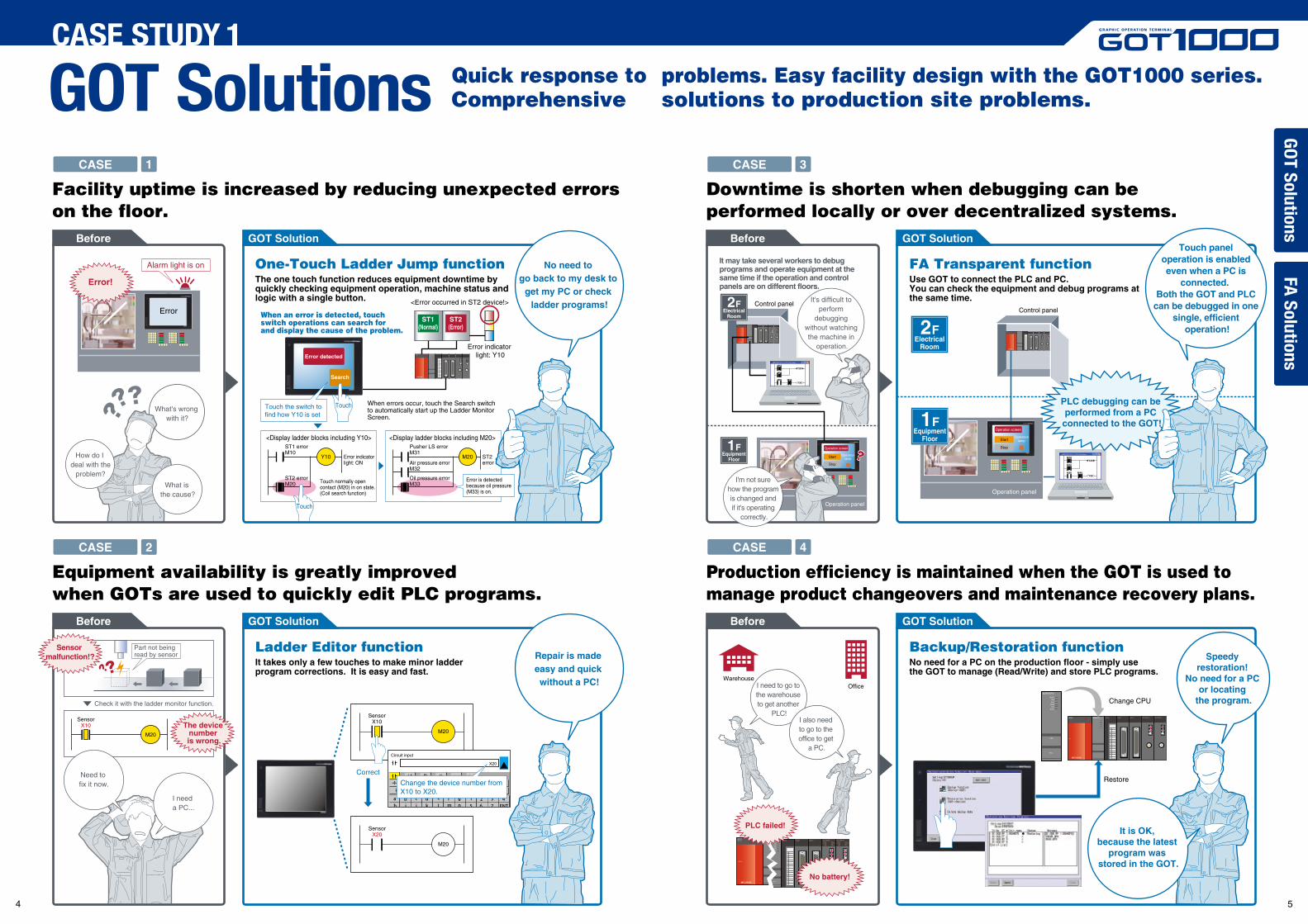
Facility uptime is increased by reducing unexpected errorson the floor.
CASE 1
CASE 2
One-Touch Ladder Jump functionThe one touch function reduces equipment downtime by quickly checking equipment operation, machine status and logic with a single button.
Ladder Editor functionIt takes only a few touches to make minor ladder program corrections. It is easy and fast.
Change the device number from X10 to X20.
Correct
No need to go back to my desk to
get my PC or check ladder programs!
Before GOT Solution
Error!
When an error is detected, touch switch operations can search for and display the cause of the problem.
Alarm light is on
Part not being read by sensor
Touch the switch to find how Y10 is set
When errors occur, touch the Search switchto automatically start up the Ladder MonitorScreen.
<Error occurred in ST2 device!>
Error indicator light: Y10
Error is detected because oil pressure (M33) is on.
Touch
Pusher LS errorM31
Air pressure errorM32
Oil pressure errorM33
M20 ST2 error
<Display ladder blocks including Y10> <Display ladder blocks including M20>ST1 errorM10
ST2 errorM20
Y10 Error indicator light: ON
Touch normally open contact (M20) in on state. (Coil search function)
Touch
Before GOT Solution
Equipment availability is greatly improved when GOTs are used to quickly edit PLC programs.
Need to fix it now.
I need a PC...
Check it with the ladder monitor function.
Sensor malfunction!?
The device number is wrong.
Repair is made easy and quick without a PC!
Speedy restoration!
No need for a PC or locating
the program.
CASE STUDY 1
Downtime is shorten when debugging can be performed locally or over decentralized systems.
FA Transparent functionUse GOT to connect the PLC and PC.You can check the equipment and debug programs at the same time.
It may take several workers to debug programs and operate equipment at the same time if the operation and control panels are on different floors.
Backup/Restoration functionNo need for a PC on the production floor - simply use the GOT to manage (Read/Write) and store PLC programs.
It is OK, because the latest
program was stored in the GOT.
Production efficiency is maintained when the GOT is used to manage product changeovers and maintenance recovery plans.
Operation panel
It's difficult to perform
debugging without watching the machine in
operation.
Control panel
OfficeWarehouse
PLC failed!
No battery!
Change CPU
Restore
Control panel
What is the cause?
How do I deal with the
problem?
What's wrong with it?
GOT SolutionsG
OT Solutions
FA Solutions
Quick response to problems. Easy facility design with the GOT1000 series.Comprehensive solutions to production site problems.
ErrorST1
(Normal)ST2(Error)
Error detected
Search
CASE 3
CASE 4
Before GOT Solution
Before GOT Solution
2FElectrical
Room
1FEquipment
Floor
I'm not sure how the program is changed and if it's operating
correctly.
Touch panel operation is enabled even when a PC is
connected. Both the GOT and PLC
can be debugged in one single, efficient
operation!2FElectrical
Room
1FEquipment
FloorOperation screen
Start
Stop
Operationlamp
Operation panel
I need to go to the warehouse to get another
PLC!I also need to go to the office to get
a PC.
4 5
Product AScrew tightening torque
100Torque 1
Torque 2 100100
History check screen
Displayoperation log
Displayalarm data
Product A
Product B
Product C
Alarm display screen01/11/2007 10:00 Error B11001/10/2007 10:10 Error B11201/10/2007 9:55 Error B110
Videosearch
120 secondsbefore
120 seconds
after
Trouble
Machine fails,forcing theline to stop!
Alarm display screen01/11/2007 10:00 Error B11001/10/2007 10:10 Error B11201/10/2007 9:55 Error B110
Manual
We can determinethe cause of the
error and this willbe helpful in
improving operationsand preventing
a recurrence in the future.
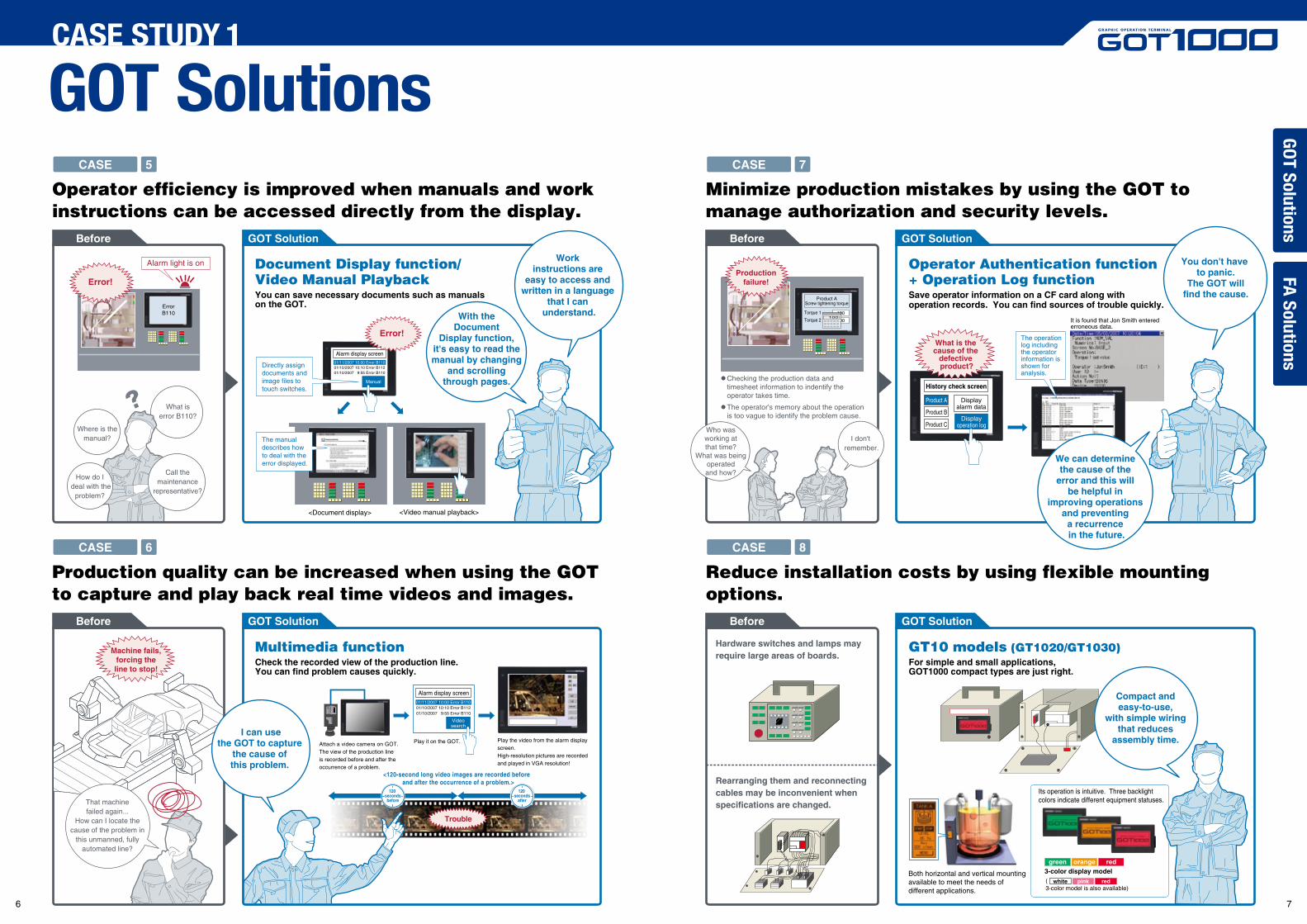
Operator efficiency is improved when manuals and work instructions can be accessed directly from the display.
Production quality can be increased when using the GOT to capture and play back real time videos and images.
Minimize production mistakes by using the GOT to manage authorization and security levels.
Reduce installation costs by using flexible mounting options.
CASE STUDY 1
GOT SolutionsG
OT Solutions
FA Solutions
Document Display function/Video Manual PlaybackYou can save necessary documents such as manuals on the GOT.
Multimedia functionCheck the recorded view of the production line. You can find problem causes quickly.
Error!Production
failure!
Alarm light is on
Call themaintenance
representative?
How do I deal with the
problem?
Where is themanual?
What iserror B110?
Its operation is intuitive. Three backlight colors indicate different equipment statuses.
Both horizontal and vertical mounting available to meet the needs of different applications.
Operator Authentication function + Operation Log functionSave operator information on a CF card along with operation records. You can find sources of trouble quickly.
GT10 models (GT1020/GT1030)For simple and small applications, GOT1000 compact types are just right.
With theDocument
Display function,it's easy to read themanual by changing
and scrollingthrough pages.
The operation log including the operator information is shown for analysis.
Directly assign documents and image files to touch switches.
<Document display>
It is found that Jon Smith entered erroneous data.
Hardware switches and lamps may require large areas of boards.
Rearranging them and reconnecting cables may be inconvenient when specifications are changed.
Error!
The manual describes how to deal with the error displayed.
Work instructions are
easy to access and written in a language
that I can understand.
I can usethe GOT to capture
the cause of this problem.
You don't have to panic.
The GOT willfind the cause.
Compact and easy-to-use,
with simple wiring that reduces
assembly time.
<Video manual playback>
CASE 5
CASE 6
Before GOT Solution
ErrorB110
Before GOT Solution
That machinefailed again...
How can I locate thecause of the problem in
this unmanned, fullyautomated line?
Attach a video camera on GOT. The view of the production line is recorded before and after the occurrence of a problem.
Play it on the GOT. Play the video from the alarm display screen.High-resolution pictures are recorded and played in VGA resolution!
<120-second long video images are recorded before and after the occurrence of a problem.>
CASE 7
CASE 8
Before GOT Solution
Before GOT Solution
Checking the production data and timesheet information to indentify the operator takes time.
The operator's memory about the operation is too vague to identify the problem cause.
Who wasworking atthat time?
What was beingoperatedand how?
I don't remember.
What is the cause of the
defective product?
3-color display modelgreen orange red
( 3-color model is also available)
white pink red
6 7
Edit Find/Replace Convert Display Online
One touch to jump to Ladder Monitor or Ladder Editor Screen
PrintScreen
PLC RD.
Exit
Mon.
Menu
Display the ladder block of the coil set to the touch switch Enter ladder program
Insert row Delete row Insert column Delete column
< > [ ]
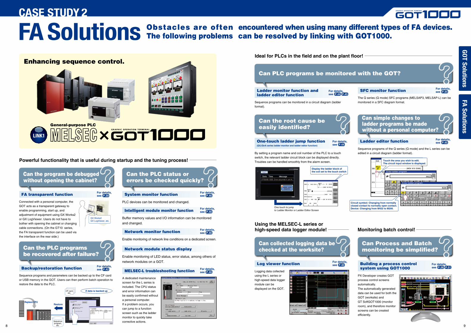
Powerful functionality that is useful during startup and the tuning process!
General-purpose PLC
Enhancing sequence control.
FA transparent function
Can the program be debugged without opening the cabinet?
Ideal for PLCs in the field and on the plant floor!
LINK1
Ladder monitor function and ladder editor function
SFC monitor function
Can PLC programs be monitored with the GOT?
Using the MELSEC-L series or high-speed data logger module! Monitoring batch control!
One-touch ladder jump function(Q/L/QnA series ladder monitor and ladder editor function)
Can the root cause be easily identified?
Ladder editor function
Can simple changes to ladder programs be made without a personal computer?
PLC devices can be monitored and changed.
System monitor function
Buffer memory values and I/O information can be monitored
and changed.
Intelligent module monitor function
Enable monitoring of network line conditions on a dedicated screen.
Network monitor function
Enable monitoring of LED status, error status, among others of
network modules on a GOT.
Network module status display
MELSEC-L troubleshooting functiion
Can the PLC status or errors be checked quickly?
Backup/restoration function
Can the PLC programs be recovered after failure?
Connected with a personal computer, the
GOT acts as a transparent gateway to
enable programming, start up, and
adjustment of equipment using GX Works2
or GX LogViewer. Users do not have to
bother with opening the cabinet or changing
cable connections. (On the GT10 series,
the FA transparent function can be used via
the interface on the rear side.)
Sequence programs and parameters can be backed up to the CF card
or USB memory in the GOT. Users can then perform batch operation to
restore the data to the PLC.
Sequence programs can be monitored in a circuit diagram (ladder
format).
The Q series (Q mode) SFC programs (MELSAP3, MELSAP-L) can be
monitored in a SFC diagram format.
By setting a program name and coil number of the PLC to a touch
switch, the relevant ladder circuit block can be displayed directly.
Troubles can be handled smoothly from the alarm screen.
Sequence programs of the Q series (Q mode) and the L series can be
edited in a circuit diagram (ladder format).
Log viewer function
Can collected logging data be checked at the worksite?
Building a process controlsystem using GOT1000
Can Process and Batch monitoring be simplified?
Logging data collected
using the L series or
high-speed data logger
module can be
displayed on the GOT.
PX Developer creates GOT
process control screens
automatically.
The automatically generated
data can be used for both the
GOT (worksite) and
GT SoftGOT1000 (monitor
room), and therefore monitor
screens can be created
efficiently.
A dedicated maintenance
screen for the L series is
included. The CPU status
and error information can
be easily confirmed without
a personal computer.
If a problem occurs, you
can jump to a function
screen such as the ladder
monitor to quickly take
corrective actions.
FA SolutionsCASE STUDY 2
GO
T Solutions
Touch the area you wish to edit. The circuit input window is displayed.
Q25HCPU
CF card,etc.
Sequenceprogram,
etc.
RestoreReplace CPU
If data is backed up
Obstacles are often encountered when using many different types of FA devices. The following problems can be resolved by linking with GOT1000.
GX Works2GX LogViewer, etc.
Enter ladder program
Insert row Delete row Insert column Delete column
< > [ ]
Circuit symbol: Changing from normally closed contact to normally open contact.Device: Changing from M422 to M200.
FA Solutions
For details,see P.39
For details,see P.42
For details,see P.46
For details,see P.46
For details,see P.46
For details,see P.46
For details,see P.44 P.45
For details,see P.44
For details,see P.40
For details,see P.44
For details,see P.45
For details,see P.26 P.51
8 9
M30 M40
M20
M10
Y30
Y20
Operation panel
Operation screen
Start
Stop
Operationlamp
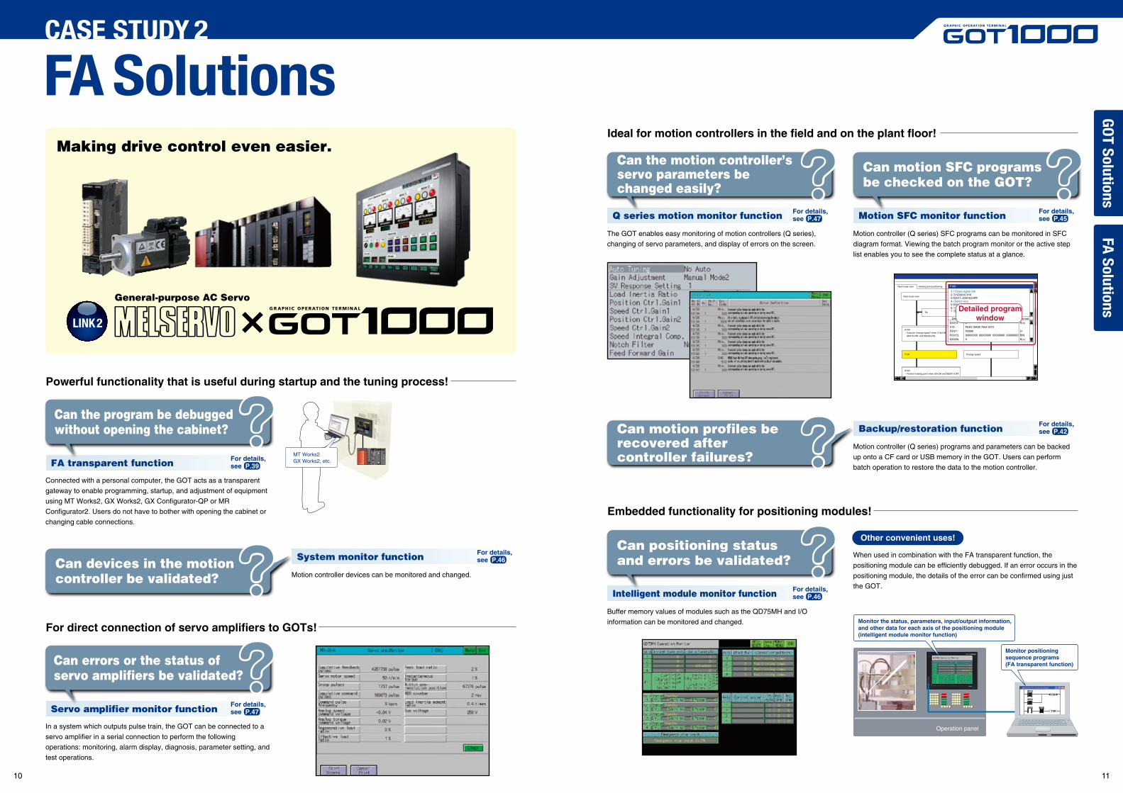
Powerful functionality that is useful during startup and the tuning process!
General-purpose AC Servo
Ideal for motion controllers in the field and on the plant floor!
LINK2
Q series motion monitor function
Can the motion controller’s servo parameters be changed easily?
Motion SFC monitor function
Can motion SFC programs be checked on the GOT?
For direct connection of servo amplifiers to GOTs!
Servo amplifier monitor function
Can errors or the status of servo amplifiers be validated?
In a system which outputs pulse train, the GOT can be connected to a
servo amplifier in a serial connection to perform the following
operations: monitoring, alarm display, diagnosis, parameter setting, and
test operations.
The GOT enables easy monitoring of motion controllers (Q series),
changing of servo parameters, and display of errors on the screen.
Embedded functionality for positioning modules!
Intelligent module monitor function
Buffer memory values of modules such as the QD75MH and I/O
information can be monitored and changed.
Motion controller (Q series) SFC programs can be monitored in SFC
diagram format. Viewing the batch program monitor or the active step
list enables you to see the complete status at a glance.
Backup/restoration function
Motion controller (Q series) programs and parameters can be backed
up onto a CF card or USB memory in the GOT. Users can perform
batch operation to restore the data to the motion controller.
When used in combination with the FA transparent function, the
positioning module can be efficiently debugged. If an error occurs in the
positioning module, the details of the error can be confirmed using just
the GOT.
Can motion profiles be recovered after controller failures?
System monitor function
Motion controller devices can be monitored and changed.Can devices in the motion controller be validated?
Can positioning status and errors be validated?
FA SolutionsCASE STUDY 2
Other convenient uses!
Monitor the status, parameters, input/output information, and other data for each axis of the positioning module(intelligent module monitor function)
Monitor positioning sequence programs (FA transparent function)
Making drive control even easier.
FA transparent function
Can the program be debugged without opening the cabinet?
MT Works2GX Works2, etc.
Connected with a personal computer, the GOT acts as a transparent
gateway to enable programming, startup, and adjustment of equipment
using MT Works2, GX Works2, GX Configurator-QP or MR
Configurator2. Users do not have to bother with opening the cabinet or
changing cable connections.
GO
T SolutionsFA
Solutions
G102Position holding point when X0=ON and M2001=OFF.
G100Execute “change speed” when X19=ON, M2415=ON, and M2345=ON.
F100
P0
Change speed
1 //Obtain digital SW2 DIND2010,X103 D2011=D2010&HFF4 //Select data5 D2012L=BIN(D2011)6 //07 D2020L=D2012K1000L
Device Value Format
D2010
X10
D2011
D2012L
D2020L
0
FEDC BA98 7654 3210
H0000
00000000 00000000 00000000 00000000
0
K(±)
H
BIN
K(+)
F100Real mode main
Real mode main
Holding point positioning
Detailed programwindow
For details,see P.39
For details,see P.47
For details,see P.46
For details,see P.47
For details,see P.46
For details,see P.45
For details,see P.42
10 11
FR Configurator
Ideal for inverter startups and operation!
General-purpose Inverter
Directly connect inverters
Can connections to the inverter be simplified?
LINK3
FA transparent function
Can the program be debugged without opening the cabinet?
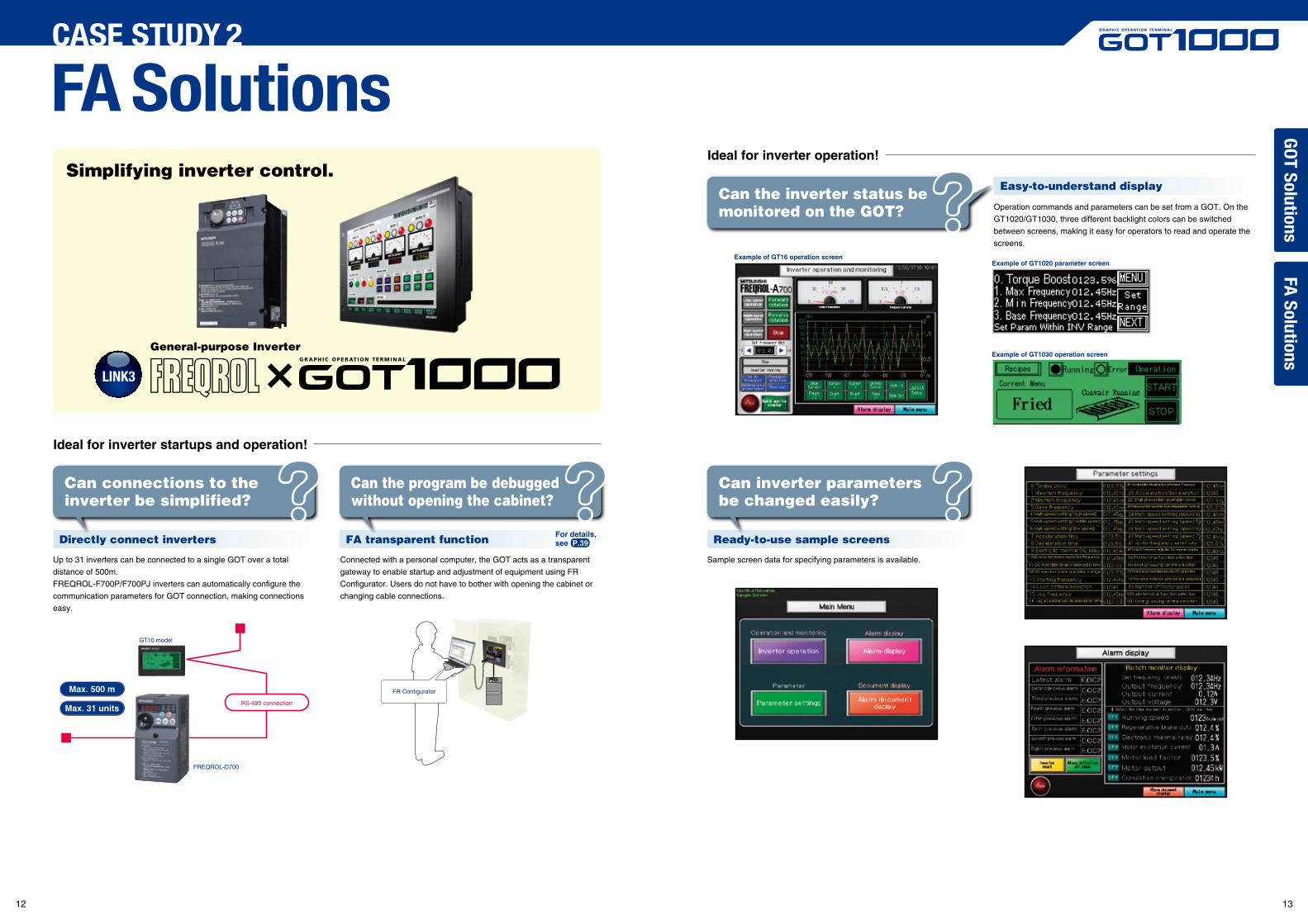
Up to 31 inverters can be connected to a single GOT over a total
distance of 500m.
FREQROL-F700P/F700PJ inverters can automatically configure the
communication parameters for GOT connection, making connections
easy.
Ready-to-use sample screens
Can inverter parameters be changed easily?
Sample screen data for specifying parameters is available. Connected with a personal computer, the GOT acts as a transparent
gateway to enable startup and adjustment of equipment using FR
Configurator. Users do not have to bother with opening the cabinet or
changing cable connections.
FA SolutionsCASE STUDY 2
Easy-to-understand display
Operation commands and parameters can be set from a GOT. On the
GT1020/GT1030, three different backlight colors can be switched
between screens, making it easy for operators to read and operate the
screens.
Can the inverter status be monitored on the GOT?
Ideal for inverter operation!
Example of GT16 operation screenExample of GT1020 parameter screen
Example of GT1030 operation screen
Simplifying inverter control.
Max. 500 m
Max. 31 unitsRS-485 connection
FREQROL-D700
GT10 model
GO
T SolutionsFA
Solutions
For details,see P.39
12 13
AUTOMANUAL
AUTOMANUAL
Powerful functions for robotic systems!
Industrial Robot
LINK4
FA SolutionsCASE STUDY 2
Ready-to-use sample screens
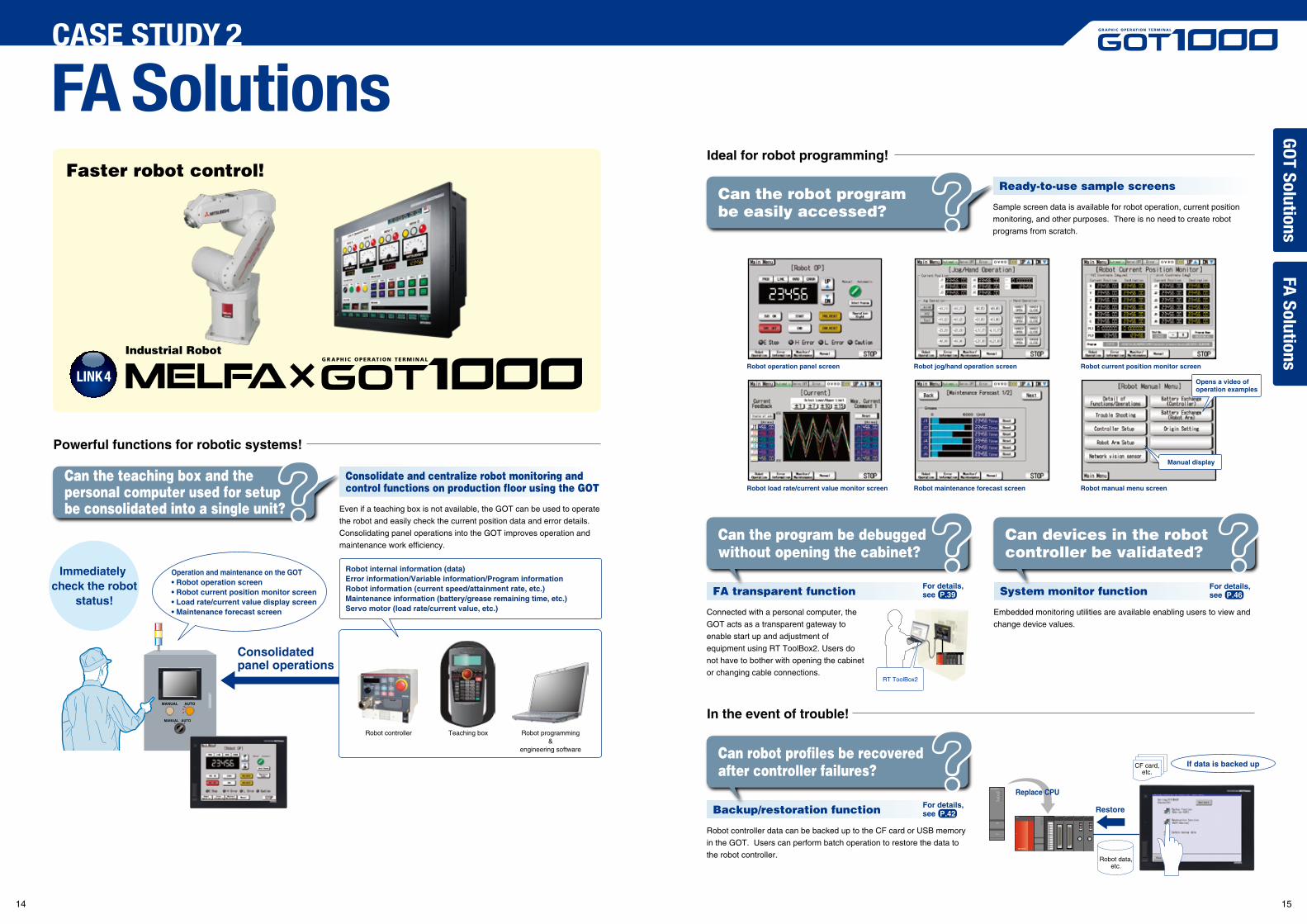
Sample screen data is available for robot operation, current position
monitoring, and other purposes. There is no need to create robot
programs from scratch.
Can the robot program be easily accessed?
Consolidate and centralize robot monitoring and control functions on production floor using the GOT
Even if a teaching box is not available, the GOT can be used to operate
the robot and easily check the current position data and error details.
Consolidating panel operations into the GOT improves operation and
maintenance work efficiency.
Can the teaching box and the personal computer used for setupbe consolidated into a single unit?
Ideal for robot programming!
Robot operation panel screen
Robot load rate/current value monitor screen
Robot jog/hand operation screen
Robot maintenance forecast screen
Robot current position monitor screen
Robot manual menu screen
Robot controller Teaching box Robot programming &
engineering software
Robot internal information (data)Error information/Variable information/Program informationRobot information (current speed/attainment rate, etc.)Maintenance information (battery/grease remaining time, etc.)Servo motor (load rate/current value, etc.)
Operation and maintenance on the GOT• Robot operation screen• Robot current position monitor screen• Load rate/current value display screen• Maintenance forecast screen
Consolidated panel operations
Immediately check the robot
status!
Opens a video of operation examples
Manual display
In the event of trouble!
Backup/restoration function
Can robot profiles be recovered after controller failures?
Robot controller data can be backed up to the CF card or USB memory
in the GOT. Users can perform batch operation to restore the data to
the robot controller.
FA transparent function
Can the program be debugged without opening the cabinet?
Connected with a personal computer, the
GOT acts as a transparent gateway to
enable start up and adjustment of
equipment using RT ToolBox2. Users do
not have to bother with opening the cabinet
or changing cable connections.
System monitor function
Can devices in the robot controller be validated?
Embedded monitoring utilities are available enabling users to view and
change device values.
Faster robot control!
RT ToolBox2
GO
T SolutionsFA
Solutions
Q25HCPU QX10 QJ71BR11QX41
0123456789ABCDEF
QJ71BR11QX41
USB
Q25HCPU
MODE
RUN
ERR
USER
BAT
BOOT
PULL
CF card,etc.
Robot data,etc.
Restore
Replace CPU
If data is backed up
For details,see P.39
For details,see P.42
For details,see P.46
14 15
Edit Find/Replace Convert Display Online
Enter ladder program
Insert row Delete row Insert column Delete column
< > [ ]
Powerful function for CNC startup, machining and changeover!
Numerical Control Unit
CNC monitor function
Ideal for CNC programming!
In the event of trouble!
Can CNC parameters be changed easily?
LINK5
One-touch ladder jump function
Can the root cause be easily identified?
Ladder editor function
Can programs be changed easily without a personal computer?
CNC data I/O function
Can errors or the status of the CNC be validated quickly?
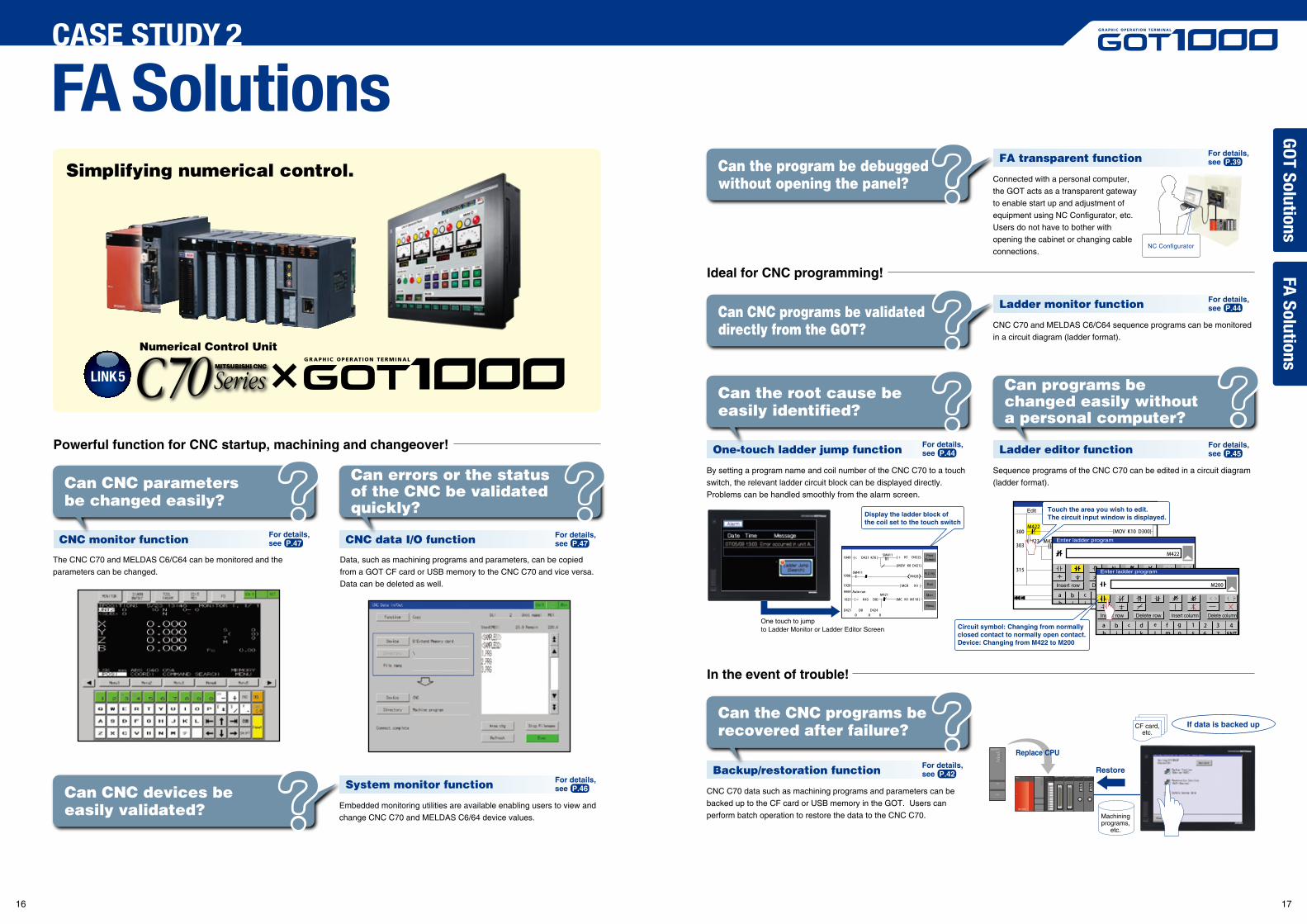
The CNC C70 and MELDAS C6/C64 can be monitored and the
parameters can be changed.
Data, such as machining programs and parameters, can be copied
from a GOT CF card or USB memory to the CNC C70 and vice versa.
Data can be deleted as well.
By setting a program name and coil number of the CNC C70 to a touch
switch, the relevant ladder circuit block can be displayed directly.
Problems can be handled smoothly from the alarm screen.
Backup/restoration function
Can the CNC programs be recovered after failure?
CNC C70 data such as machining programs and parameters can be
backed up to the CF card or USB memory in the GOT. Users can
perform batch operation to restore the data to the CNC C70.
Sequence programs of the CNC C70 can be edited in a circuit diagram
(ladder format).
FA SolutionsCASE STUDY 2
System monitor function
Embedded monitoring utilities are available enabling users to view and
change CNC C70 and MELDAS C6/64 device values.
Can CNC devices be easily validated?
FA transparent function
Connected with a personal computer,
the GOT acts as a transparent gateway
to enable start up and adjustment of
equipment using NC Configurator, etc.
Users do not have to bother with
opening the cabinet or changing cable
connections.
Can the program be debugged without opening the panel?
Ladder monitor function
CNC C70 and MELDAS C6/C64 sequence programs can be monitored
in a circuit diagram (ladder format).
Can CNC programs be validated directly from the GOT?
Simplifying numerical control.
GO
T SolutionsFA
Solutions
One touch to jump to Ladder Monitor or Ladder Editor Screen
PrintScreen
PLC RD.
Exit
Mon.
Menu
Display the ladder block of the coil set to the touch switch
Q25HCPU QX10 QJ71BR11QX41
0123456789ABCDEF
QJ71BR11QX41
USB
Q25HCPU
MODE
RUN
ERR
USER
BAT
BOOT
PULL
CF card,etc.
Machiningprograms,
etc.
Restore
Replace CPU
If data is backed up
NC Configurator
Touch the area you wish to edit. The circuit input window is displayed.
Enter ladder program
Insert row Delete row Insert column Delete column
< > [ ]
Circuit symbol: Changing from normally closed contact to normally open contact.Device: Changing from M422 to M200
For details,see P.47
For details,see P.47
For details,see P.46
For details,see P.44
For details,see P.42
For details,see P.39
For details,see P.44
For details,see P.45
16 17
Powerful functions for vision systems!
LINK6
FA SolutionsCASE STUDY 2
Ready-to-use sample screens
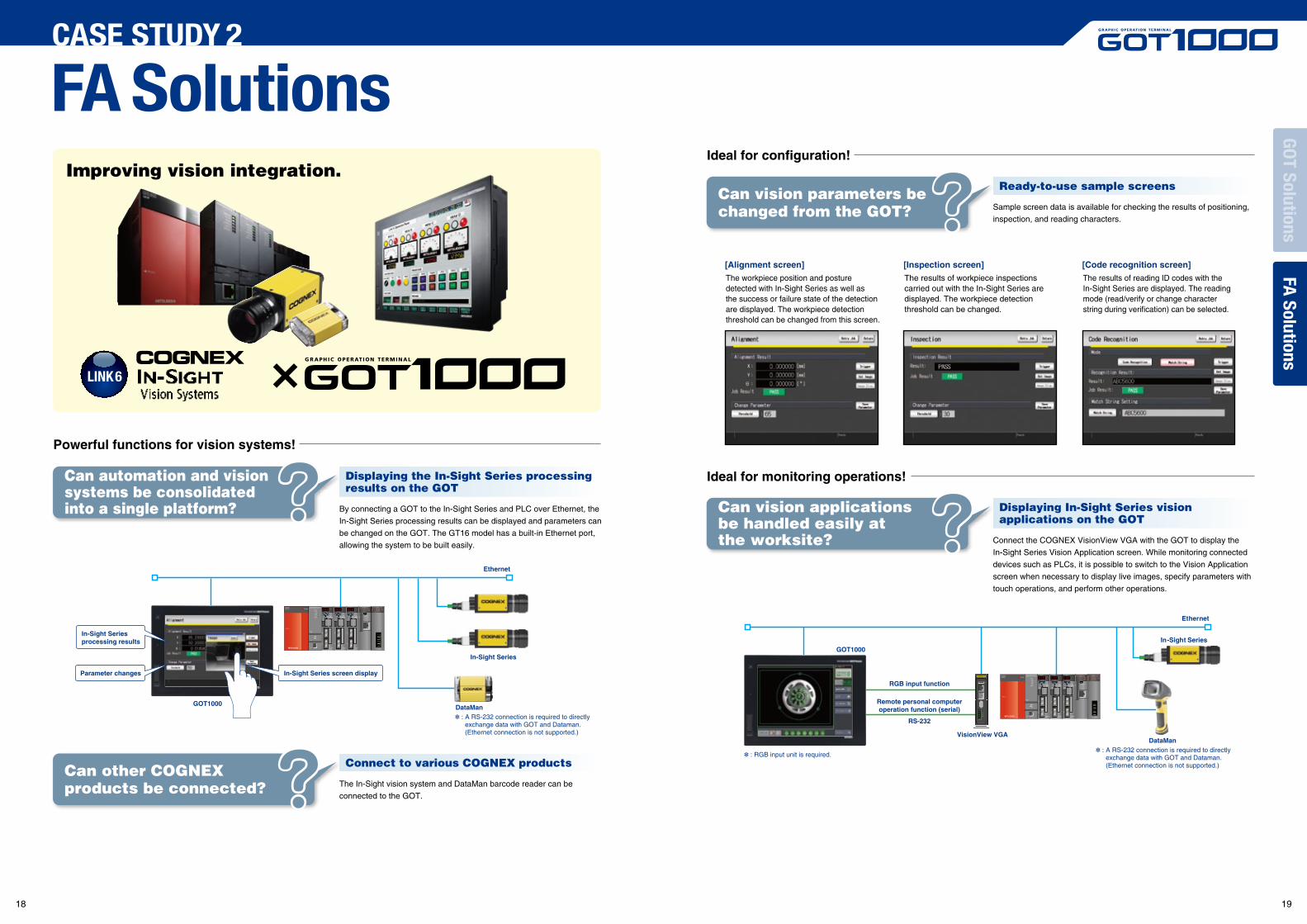
Sample screen data is available for checking the results of positioning,
inspection, and reading characters.
The workpiece position and posture detected with In-Sight Series as well as the success or failure state of the detection are displayed. The workpiece detection threshold can be changed from this screen.
Can vision parameters be changed from the GOT?
Displaying the In-Sight Series processing results on the GOT
By connecting a GOT to the In-Sight Series and PLC over Ethernet, the
In-Sight Series processing results can be displayed and parameters can
be changed on the GOT. The GT16 model has a built-in Ethernet port,
allowing the system to be built easily.
Can automation and vision systems be consolidated into a single platform?
Connect to various COGNEX products
The In-Sight vision system and DataMan barcode reader can be
connected to the GOT.
Can other COGNEX products be connected?
Ideal for configuration!
Displaying In-Sight Series vision applications on the GOT
Connect the COGNEX VisionView VGA with the GOT to display the
In-Sight Series Vision Application screen. While monitoring connected
devices such as PLCs, it is possible to switch to the Vision Application
screen when necessary to display live images, specify parameters with
touch operations, and perform other operations.
Can vision applications be handled easily at the worksite?
Ideal for monitoring operations!
[Alignment screen]The results of workpiece inspections carried out with the In-Sight Series are displayed. The workpiece detection threshold can be changed.
[Inspection screen]The results of reading ID codes with the In-Sight Series are displayed. The reading mode (read/verify or change character string during verification) can be selected.
[Code recognition screen]
GOT1000
GOT1000
Parameter changes In-Sight Series screen display
In-Sight Series processing results
Ethernet
Ethernet
RGB input function
VisionView VGA
Remote personal computeroperation function (serial)
RS-232
In-Sight Series
DataMan
: RGB input unit is required.
: A RS-232 connection is required to directly exchange data with GOT and Dataman. (Ethernet connection is not supported.)
DataMan : A RS-232 connection is required to directly
exchange data with GOT and Dataman. (Ethernet connection is not supported.)
Improving vision integration.
In-Sight Series
GO
T SolutionsFA
Solutions
18 19
TFTGT1155-QTBDGT1155-QTBDQGT1155-QTBDA
Q bus connection
A bus connection
Resolution : 320 × 240 Display colors : 256 colors
QVGA
STNGT1155-QSBDGT1155-QSBDQGT1155-QSBDA
Q bus connection
A bus connection
Resolution : 320 × 240 Display colors : 256 colors
QVGA
GT1150-QLBDGT1150-QLBDQGT1150-QLBDA
Q bus connection
A bus connection
Resolution : 320 × 240 Display colors : 16 gray scales
GT1150HS-QLBD
Handy GOT/STN
Resolution : 320 × 240 Display colors : 256 colors
QVGAGT1155HS-QSBD
AC type DC type
Resolution : 320 × 240 Display colors : 16 gray scales
5.7" type 5.7" type Handy
Small models with a host of advanced functions
GT11GOT1000 GRAPHIC OPERATION TERMINAL
TFT
Resolution : 640 × 480 Display colors : 256 colors
VGAGT1275-VNBA AC type GT1275-VNBD
TFT
Resolution : 640 × 480 Display colors : 256 colors
VGAGT1265-VNBA GT1265-VNBD
10.4" type 8.4" type
Large basic models with integrated featuresand communications
GT12GOT1000 GRAPHIC OPERATION TERMINAL
Multimedia Video RGB BusNetwork Serial Multimedia Video RGB Network Bus SerialDC type DC type
DC type
DC type
DC type
DC type
DC type
DC type
DC type
DC typeDC type
DC type
TFT(High-brightness, wide viewing angle)GT1595-XTBA GT1595-XTBD
Resolution : 1024 × 768 Display colors : 65,536 colors
XGA TFT(High-brightness, wide viewing angle)GT1585-STBA GT1585-STBD
Resolution : 800 × 600 Display colors : 65,536 colors
SVGA TFT(High-brightness, wide viewing angle)GT1575-STBA GT1575-STBD
Resolution : 800 × 600 Display colors : 65,536 colors
SVGA TFTGT1562-VNBA GT1562-VNBD
Resolution : 640 × 480 Display colors : 16 colors
VGA TFT(High-brightness, wide viewing angle)GT1555-QTBD
Resolution : 320 × 240 Display colors : 65,536 colors
QVGA
TFT(High-brightness, wide viewing angle)GT1555-VTBD
Resolution : 640 × 480 Display colors : 65,536 colors
VGA STNGT1555-QSBD
Resolution : 320 × 240 Display colors : 4,096 colors
QVGA STNGT1550-QLBD
Resolution : 320 × 240 Display colors : 16 gray scales
QVGATFT(High-brightness, wide viewing angle)GT1565-VTBA GT1565-VTBD
Resolution : 640 × 480 Display colors : 65,536 colors
VGA
TFTGT1572-VNBA GT1572-VNBD
Resolution : 640 × 480 Display colors : 16 colors
VGA
TFTGT1575-VNBA GT1575-VNBD
Resolution : 640 × 480 Display colors : 256 colors
VGA
TFT(High-brightness, wide viewing angle)GT1575-VTBA GT1575-VTBD
Resolution : 640 × 480 Display colors : 65,536 colors
VGA
TFT(High-brightness, wide viewing angle)GT1585V-STBA GT1585V-STBD
Resolution : 800 × 600 Display colors : 65,536 colorsVideo/RGB model
SVGA TFT(High-brightness, wide viewing angle)GT1575V-STBA GT1575V-STBD
Resolution : 800 × 600 Display colors : 65,536 colorsVideo/RGB model
SVGA
5.7" type8.4" type10.4" type12.1" type15" type
Performance models ideal for a wide range ofapplications in a network or standalone environment
Multimedia
GT15Video RGB Network Bus Serial
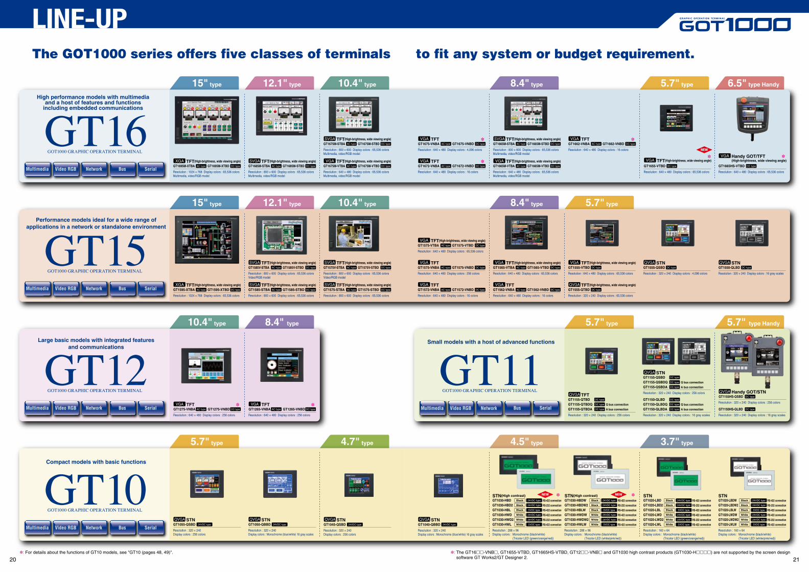
The GOT1000 series offers five classes of terminals to fit any system or budget requirement.
GOT1000 GRAPHIC OPERATION TERMINAL
STN(High contrast)
RS-232 connection
Multimedia Video RGB Network Bus
TFT(High-brightness, wide viewing angle)GT1695M-XTBA AC type GT1695M-XTBD DC type AC type DC type
Resolution : 1024 × 768 Display colors : 65,536 colorsMultimedia, video/RGB model
XGA TFT(High-brightness, wide viewing angle)GT1685M-STBA GT1685M-STBD
Resolution : 800 × 600 Display colors : 65,536 colorsMultimedia, video/RGB model
SVGA TFT(High-brightness, wide viewing angle)GT1675M-VTBA GT1675M-VTBD
Resolution : 640 × 480 Display colors : 65,536 colorsMultimedia, video/RGB model
VGA
TFT(High-brightness, wide viewing angle)GT1675M-STBA GT1675M-STBD
Resolution : 800 × 600 Display colors : 65,536 colorsMultimedia, video/RGB model
SVGA
5.7" type 6.5" type Handy8.4" type10.4" type12.1" type15" type
GT16Video RGBMultimedia Network Bus Serial
GOT1000 GRAPHIC OPERATION TERMINAL
STNGT1055-QSBD 24VDC type 24VDC type
Resolution : 320 × 240Display colors : 256 colors
QVGA STNGT1050-QBBD
Resolution : 320 × 240Display colors : Monochrome (blue/white) 16 gray scales
QVGA STNQVGA STNQVGA24VDC typeGT1045-QSBD
Resolution : 320 × 240Display colors : Monochrome (blue/white) 16 gray scales
Resolution : 320 × 240Display colors : 256 colors
24VDC typeGT1040-QBBD
TFTGT1675-VNBA GT1675-VNBD
Resolution : 640 × 480 Display colors : 4,096 colors
VGA
TFTGT1672-VNBA GT1672-VNBD
Resolution : 640 × 480 Display colors : 16 colors
VGA TFT(High-brightness, wide viewing angle)GT1665M-VTBA GT1665M-VTBD
Resolution : 640 × 480 Display colors : 65,536 colorsMultimedia, video/RGB model
VGAHandy GOT/TFT(High-brightness, wide viewing angle)
GT1665HS-VTBD
Resolution : 640 × 480 Display colors : 65,536 colors
VGA
TFT(High-brightness, wide viewing angle)GT1665M-STBA GT1665M-STBD
Resolution : 800 × 600 Display colors : 65,536 colorsMultimedia, video/RGB model
SVGA TFTGT1662-VNBA GT1662-VNBD
Resolution : 640 × 480 Display colors : 16 colors
VGA
TFT(High-brightness, wide viewing angle)
GT1655-VTBD
Resolution : 640 × 480 Display colors : 65,536 colors
VGA
NEW
NEW NEW
GT1030-HWD2RS-422 connectionGT1030-HWL
RS-422 connectionGT1030-HWD White
White
White
RS-232 connectionGT1030-HBD2RS-422 connectionGT1030-HBL
RS-422 connectionGT1030-HBD Black
Black
Black
White
White
White
Black
Black
Black
Resolution : 288 × 96Display colors : Monochrome (black/white) (Tricolor LED (green/orange/red))
STN(High contrast)
GT1030-HWDW2GT1030-HWLW
GT1030-HWDW
GT1030-HBDW2GT1030-HBLW
GT1030-HBDW
Resolution : 288 × 96Display colors : Monochrome (black/white) (Tricolor LED (white/pink/red))
STN
GT1020-LWLGT1020-LWD2GT1020-LWD
GT1020-LBD
GT1020-LBLGT1020-LBD2
Resolution : 160 × 64Display colors : Monochrome (black/white) (Tricolor LED (green/orange/red))
STN
GT1020-LWLWGT1020-LWDW2GT1020-LWDW
GT1020-LBDW
GT1020-LBLWGT1020-LBDW2
Resolution : 160 × 64Display colors : Monochrome (black/white) (Tricolor LED (white/pink/red))
5.7" type 4.7" type 4.5" type 3.7" type
Compact models with basic functions
GT10Serial
GOT1000 GRAPHIC OPERATION TERMINAL
LINE-UP
AC type DC type AC type DC type
AC type DC type
AC type DC type
AC type DC type
AC type DC type
AC type DC type
AC type DC type
AC type DC type
AC type DC type
AC type DC type
AC type DC type
AC type DC type AC type DC type
DC type DC typeAC type DC type
AC type DC type
AC type DC type
DC type DC type DC type
DC type
24VDC type
24VDC type
5VDC type
24VDC type
24VDC type
5VDC type
RS-232 connection
RS-422 connection
RS-422 connection
RS-232 connection
RS-422 connection
RS-422 connection24VDC type
24VDC type
5VDC type
24VDC type
24VDC type
5VDC type
White
White
White
Black
Black
Black
RS-232 connection
RS-422 connection
RS-422 connection
RS-232 connection
RS-422 connection
RS-422 connection24VDC type
24VDC type
5VDC type
24VDC type
24VDC type
5VDC type
White
White
White
Black
Black
Black
RS-232 connection
RS-422 connection
RS-422 connection
RS-232 connection
RS-422 connection
RS-422 connection24VDC type
24VDC type
5VDC type
24VDC type
24VDC type
5VDC type
: The GT16-VNB, GT1655-VTBD, GT1665HS-VTBD, GT12-VNB and GT1030 high contrast products (GT1030-H) are not supported by the screen designsoftware GT Works2/GT Designer 2.
: For details about the functions of GT10 models, see "GT10 (pages 48, 49)".
High performance models with multimediaand a host of features and functions
including embedded communications
20 21
GT1695/GT1685 onlyConnect communication units and other optional units
You can use a USB memory stick.
Connect communication units and other optional units
GT16 See page 24 for GT16 Handy.
GT1595/GT1585(V) only
Compact models with basic functionsGT15
RS-232, and RS-422/485
USB device CF card
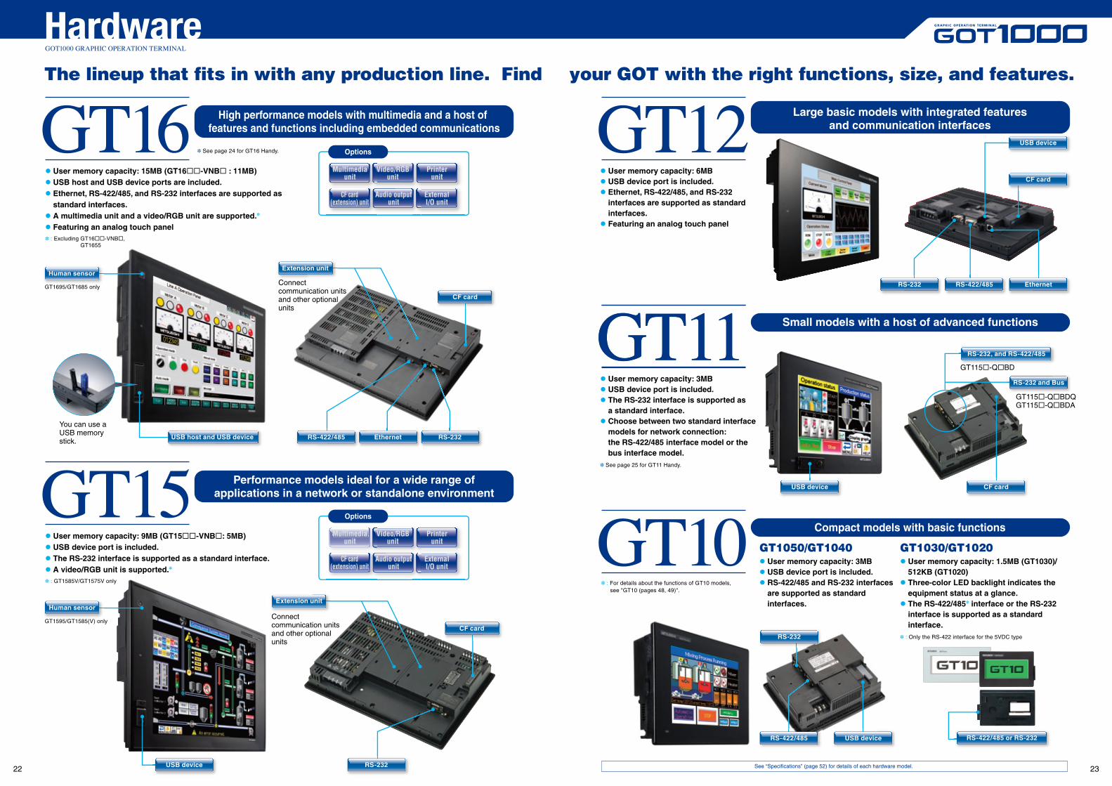
GT11 User memory capacity: 3MB USB device port is included. The RS-232 interface is supported as a standard interface. Choose between two standard interface
models for network connection: the RS-422/485 interface model or thebus interface model.
See page 25 for GT11 Handy.
GT115-QBD
RS-232 and Bus
GT115-QBDQGT115-QBDA
GT10 GT1050/GT1040 User memory capacity: 3MB USB device port is included. RS-422/485 and RS-232 interfaces
are supported as standardinterfaces.
GT1030/GT1020 User memory capacity: 1.5MB (GT1030)/
512KB (GT1020) Three-color LED backlight indicates the
equipment status at a glance. The RS-422/485 interface or the RS-232
interface is supported as a standardinterface.
: Only the RS-422 interface for the 5VDC type
See “Specifications” (page 52) for details of each hardware model.
Video/RGBunit
VMultimediaunit
Printerunit
CF card(extension) unit
ExternalI/O unit
Audio outputunit
GOT1000 GRAPHIC OPERATION TERMINAL
The lineup that fits in with any production line. Find your GOT with the right functions, size, and features.
Options
Options
Video/RGBunit
VMultimediaunit
Printerunit
CF card(extension) unit
ExternalI/O unit
Audio outputunit
Hardware
RS-232
USB deviceRS-422/485 RS-422/485 or RS-232
EthernetRS-422/485RS-232
USB device
CF card
GT12
GT11
High performance models with multimedia and a host of features and functions including embedded communications
Performance models ideal for a wide range ofapplications in a network or standalone environment
Small models with a host of advanced functions
User memory capacity: 15MB (GT16-VNB : 11MB) USB host and USB device ports are included. Ethernet, RS-422/485, and RS-232 interfaces are supported as
standard interfaces. A multimedia unit and a video/RGB unit are supported.
Featuring an analog touch panel : Excluding GT16-VNB, GT1655
User memory capacity: 9MB (GT15-VNB: 5MB) USB device port is included. The RS-232 interface is supported as a standard interface. A video/RGB unit is supported.
: GT1585V/GT1575V only
USB host and USB device RS-422/485 Ethernet RS-232
Extension unitHuman sensor
CF card
RS-232USB device
Extension unitHuman sensor
CF card
Large basic models with integrated featuresand communication interfaces
User memory capacity: 6MB USB device port is included. Ethernet, RS-422/485, and RS-232
interfaces are supported as standardinterfaces.
Featuring an analog touch panel
: For details about the functions of GT10 models, see "GT10 (pages 48, 49)".
22 23
GT16GOT1000 GRAPHIC OPERATION TERMINAL
Hardware
Handy GOT
Rich functionality and high performance in the palm of your hand
GT11Handy GOT
65,536 vivid colors on a big VGA screen
Portable 5.7" operation terminal
allows you to change the angle of the handle.
The light body includes the latest GT16 functions
Extremely easy handling and operation in one hand
Standard Ethernet interface enables long-distance communication
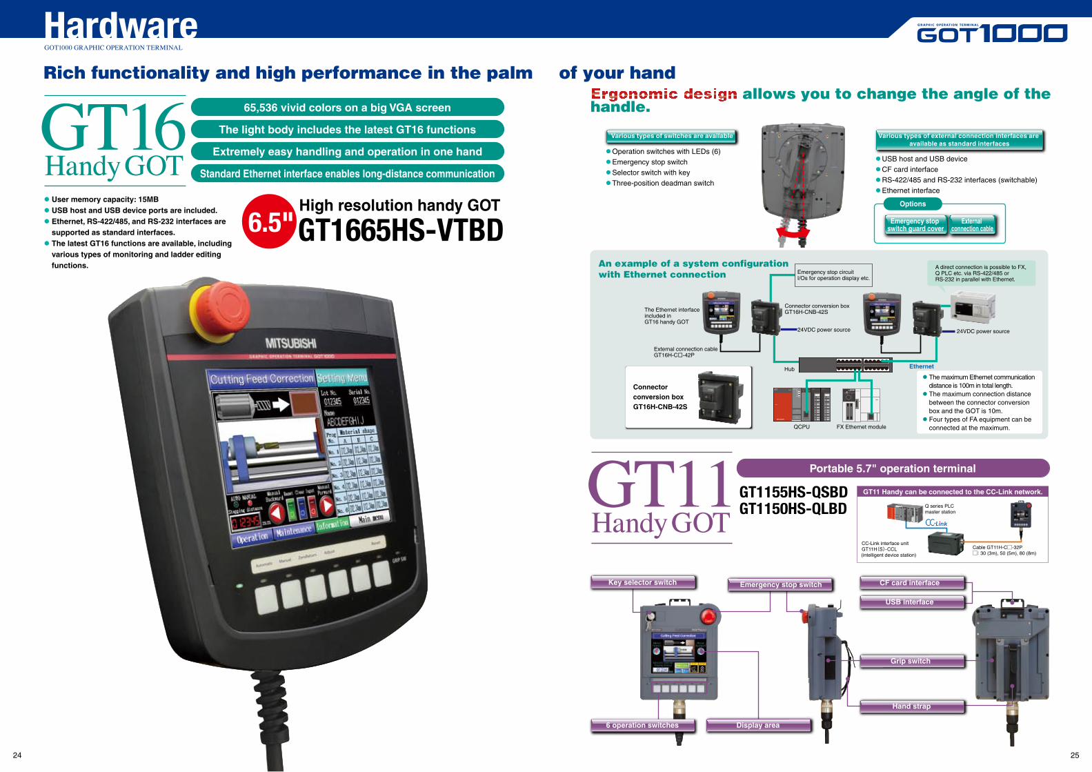
High resolution handy GOT
GT1665HS-VTBD6.5"
Operation switches with LEDs (6) Emergency stop switch Selector switch with key Three-position deadman switch
USB host and USB device CF card interface RS-422/485 and RS-232 interfaces (switchable) Ethernet interface
Options
Emergency stop switch guard cover
External connection cable
An example of a system configuration with Ethernet connection
Connector conversion boxGT16H-CNB-42S
Connector conversion boxGT16H-CNB-42S
Emergency stop circuitI/Os for operation display etc.
24VDC power source
FX Ethernet moduleQCPU
Hub
24VDC power source
Ethernet
A direct connection is possible to FX, Q PLC etc. via RS-422/485 or RS-232 in parallel with Ethernet.
The Ethernet interface included in GT16 handy GOT
GT1155HS-QSBDGT1150HS-QLBD
External connection cableGT16H-C-42P
Various types of switches are available Various types of external connection interfaces are available as standard interfaces
User memory capacity: 15MB USB host and USB device ports are included. Ethernet, RS-422/485, and RS-232 interfaces are
supported as standard interfaces. The latest GT16 functions are available, including
various types of monitoring and ladder editing functions.
The maximum Ethernet communication distance is 100m in total length. The maximum connection distance
between the connector conversion box and the GOT is 10m. Four types of FA equipment can be
connected at the maximum.
USB interface
CF card interface
Hand strap
Grip switch
Key selector switch Emergency stop switch
6 operation switches Display area
CC-Link interface unitGT11H(S)-CCL(intelligent device station)
Cable GT11H-C-32P: 30 (3m), 50 (5m), 80 (8m)
GT11 Handy can be connected to the CC-Link network.
Q series PLCmaster station
24 25
GOT1000 GRAPHIC OPERATION TERMINAL
SoftwareUse a personal computer or panel computer as a GOT.
Version3
Monitor the production site from a remote location
Connect with MELSEC process control for process control applications
The SoftGOT-GOT link function enhances the linkage to your onsite GOT
Link with other applications to constructa high-performance system
PX Developer window screens and other tools
See "List of connectable models" (page 69), "Function list" (page 70), and "Notes for use (Operating environment)" (page 85).
USB port license key
NEW
GT SoftGOT1000GT SoftGOT1000 is the HMI software that provides GOT functions on personal computers and panel computers.This software connects with various types of equipment such as Mitsubishi PLCs and let you see screens just like the GOT1000 series.You can also reuse GOT's project data without modification.Along with all the advantages of a GOT, you can also enjoy the convenience and flexibility of personal computers and panel computers.
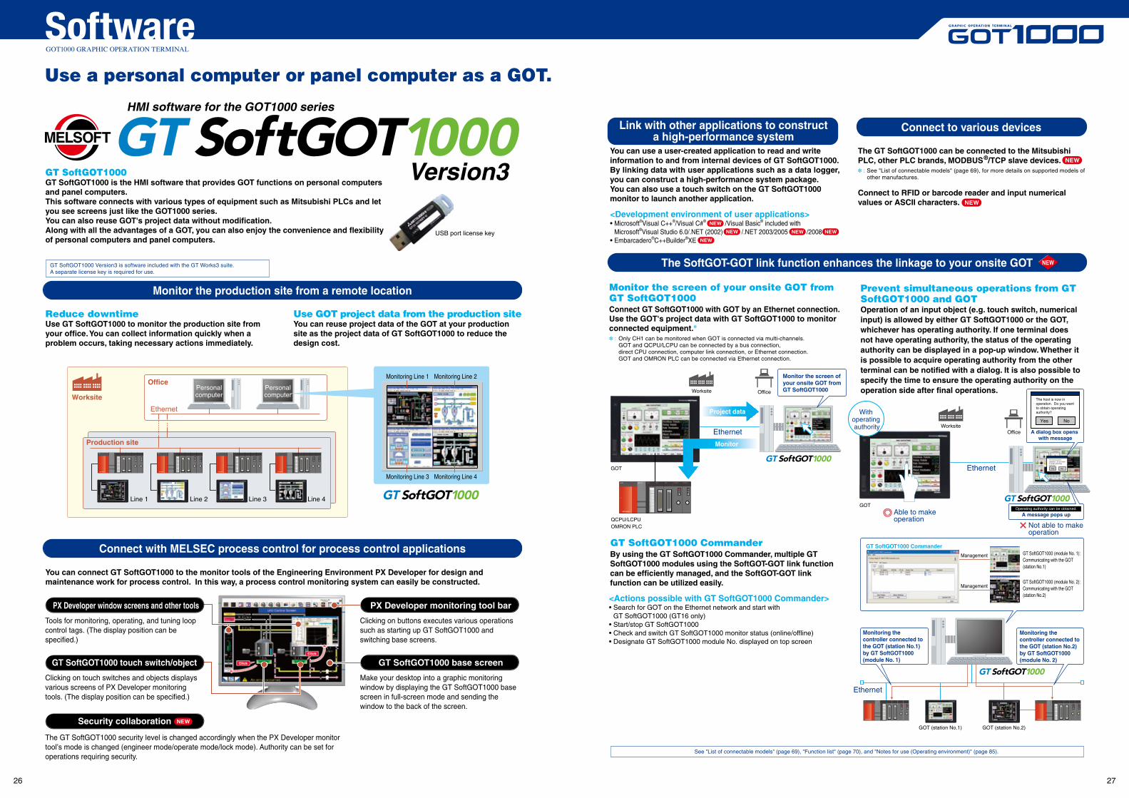
Reduce downtimeUse GT SoftGOT1000 to monitor the production site from your office. You can collect information quickly when a problem occurs, taking necessary actions immediately.
You can connect GT SoftGOT1000 to the monitor tools of the Engineering Environment PX Developer for design and maintenance work for process control. In this way, a process control monitoring system can easily be constructed.
You can use a user-created application to read and write information to and from internal devices of GT SoftGOT1000. By linking data with user applications such as a data logger, you can construct a high-performance system package.You can also use a touch switch on the GT SoftGOT1000 monitor to launch another application.
<Development environment of user applications>• Microsoft®Visual C++®/Visual C#® /Visual Basic® included with Microsoft®Visual Studio 6.0/.NET (2002) /.NET 2003/2005 /2008 • Embarcadero®C++Builder®XE
The GT SoftGOT1000 can be connected to the Mitsubishi PLC, other PLC brands, MODBUS®/TCP slave devices. : See "List of connectable models" (page 69), for more details on supported models of
other manufactures.
Connect to RFID or barcode reader and input numerical values or ASCII characters.
Monitor the screen of your onsite GOT from GT SoftGOT1000Connect GT SoftGOT1000 with GOT by an Ethernet connection.Use the GOT's project data with GT SoftGOT1000 to monitor connected equipment.
: Only CH1 can be monitored when GOT is connected via multi-channels. GOT and QCPU/LCPU can be connected by a bus connection, direct CPU connection, computer link connection, or Ethernet connection. GOT and OMRON PLC can be connected via Ethernet connection.
Use GOT project data from the production siteYou can reuse project data of the GOT at your production site as the project data of GT SoftGOT1000 to reduce the design cost.
Line 1 Line 2 Line 3 Line 4
Personalcomputer
Personalcomputer
Production site
Office
Worksite
Ethernet
Monitoring Line 1 Monitoring Line 2
Monitoring Line 4Monitoring Line 3
Tools for monitoring, operating, and tuning loop control tags. (The display position can be specified.)
GT SoftGOT1000 touch switch/object
Clicking on touch switches and objects displays various screens of PX Developer monitoring tools. (The display position can be specified.)
The GT SoftGOT1000 security level is changed accordingly when the PX Developer monitor tool’s mode is changed (engineer mode/operate mode/lock mode). Authority can be set for operations requiring security.
PX Developer monitoring tool bar
Clicking on buttons executes various operations such as starting up GT SoftGOT1000 and switching base screens.
GT SoftGOT1000 base screen
Make your desktop into a graphic monitoring window by displaying the GT SoftGOT1000 base screen in full-screen mode and sending the window to the back of the screen.
HMI software for the GOT1000 series
NEWSecurity collaboration
Connect to various devices
NEW
NEW
NEW
NEW
NEW
NEW
GT SoftGOT1000 CommanderGT SoftGOT1000 Commander
Ethernet
Management
Management
GOT (station No.1) GOT (station No.2)
<Actions possible with GT SoftGOT1000 Commander>• Search for GOT on the Ethernet network and start with
GT SoftGOT1000 (GT16 only)• Start/stop GT SoftGOT1000• Check and switch GT SoftGOT1000 monitor status (online/offline)• Designate GT SoftGOT1000 module No. displayed on top screen
GT SoftGOT1000 (module No. 1):Communicating with the GOT(station No.1)
GT SoftGOT1000 (module No. 2):Communicating with the GOT(station No.2)
By using the GT SoftGOT1000 Commander, multiple GT SoftGOT1000 modules using the SoftGOT-GOT link function can be efficiently managed, and the SoftGOT-GOT link function can be utilized easily.
NEW
Monitoring the controller connected to the GOT (station No.1)by GT SoftGOT1000 (module No. 1)
Monitoring the controller connected to the GOT (station No.2) by GT SoftGOT1000 (module No. 2)
Ethernet
GOT
QCPU/LCPUOMRON PLC
Q25HCPU QX10 QJ71BR11QX41
0123456789ABCDEF
QJ71BR11QX41
Ethernet
Not able to make operation
Office
Prevent simultaneous operations from GT SoftGOT1000 and GOTOperation of an input object (e.g. touch switch, numerical input) is allowed by either GT SoftGOT1000 or the GOT, whichever has operating authority. If one terminal does not have operating authority, the status of the operating authority can be displayed in a pop-up window. Whether it is possible to acquire operating authority from the other terminal can be notified with a dialog. It is also possible to specify the time to ensure the operating authority on the operation side after final operations.
NoYes
The host is now in operation. Do you want to obtain operating authority?
Able to makeoperation
Worksite
GOT
With operating authority
Monitor the screen of your onsite GOT from GT SoftGOT1000Worksite Office
Monitor
A dialog box opens with message
NoYes
The host is now in operation. Do you want to obtain operating authority?
A message pops up
Q25HCPU QX10 QJ71BR11QX41
0123456789ABCDEF
QJ71BR11QX41
GT SoftGOT1000 Version3 is software included with the GT Works3 suite.A separate license key is required for use.
Project data
Operating authority can be obtained.
26 27
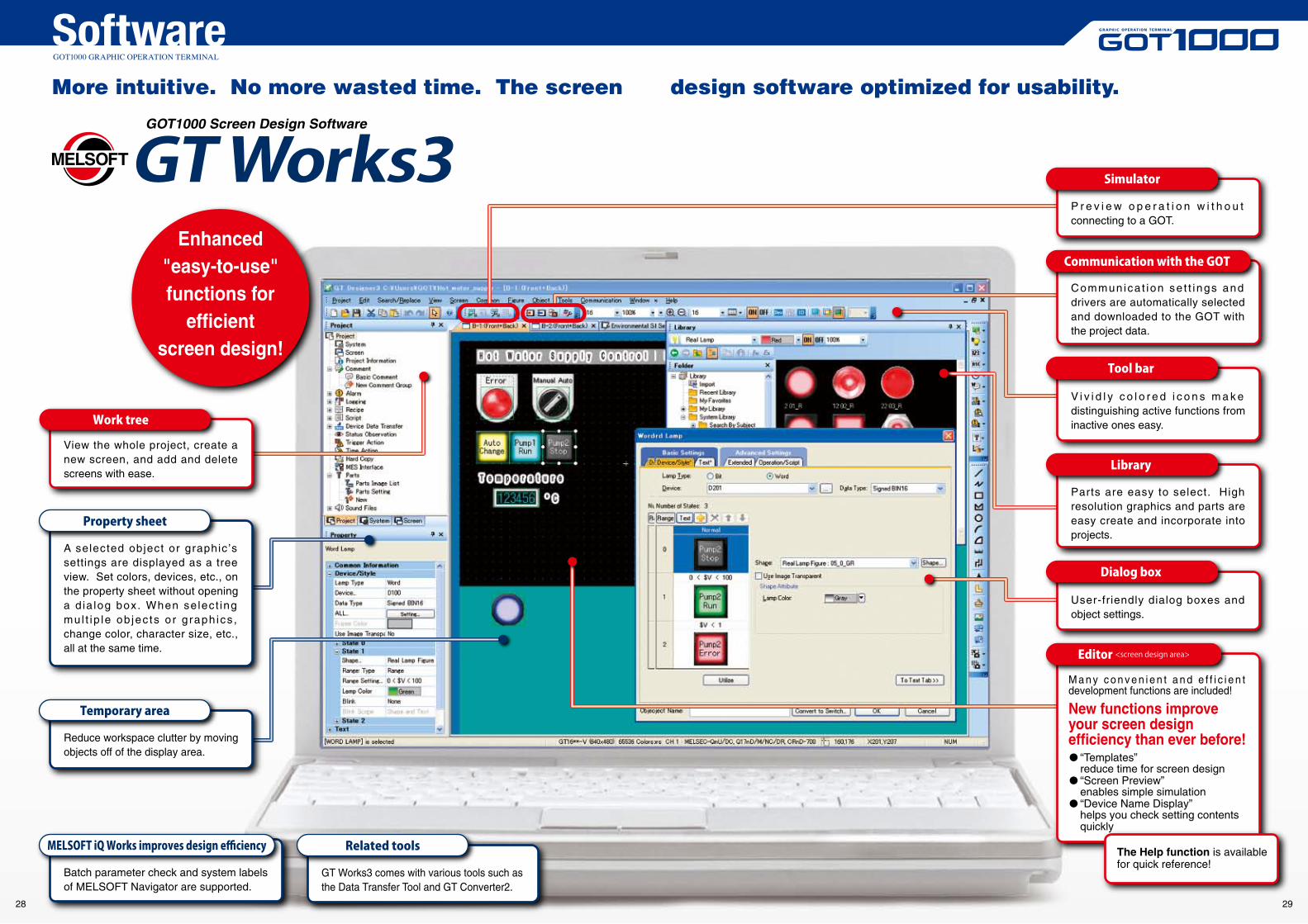
View the whole project, create a new screen, and add and delete screens with ease.
A selected object or graphic’s settings are displayed as a tree view. Set colors, devices, etc., on the property sheet without opening a d ia log box. When se lect ing mul t ip le ob jec ts o r g raph ics , change color, character size, etc., all at the same time.
Property sheet
Reduce workspace clutter by moving objects off of the display area.
Temporary area
Batch parameter check and system labels of MELSOFT Navigator are supported.
MELSOFT iQ Works improves design efficiency
GT Works3 comes with various tools such as the Data Transfer Tool and GT Converter2.
Related tools
Work tree
Enhanced "easy-to-use" functions for
efficient screen design!
Communica t ion se t t ings and drivers are automatically selected and downloaded to the GOT with the project data.
Communication with the GOT
P r e v i e w o p e r a t i o n w i t h o u t connecting to a GOT.
Simulator
V i v i d l y c o l o r e d i c o n s m a k e distinguishing active functions from inactive ones easy.
Tool bar
Parts are easy to select. High resolution graphics and parts are easy create and incorporate into projects.
Library
User-friendly dialog boxes and object settings.
Dialog box
Editor <screen design area>
New functions improve your screen design efficiency than ever before!
M a n y c o n v e n i e n t a n d e f f i c i e n t development functions are included!
“Templates” reduce time for screen design “Screen Preview” enables simple simulation “Device Name Display” helps you check setting contents quickly
The Help function is available for quick reference!
More intuitive. No more wasted time. The screen design software optimized for usability.
GOT1000 Screen Design Software
GOT1000 GRAPHIC OPERATION TERMINAL
Software
28 29
CONTENTSGOT1000 GRAPHIC OPERATION TERMINAL
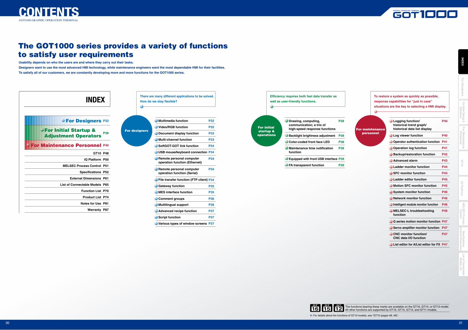
The GOT1000 series provides a variety of functions to satisfy user requirementsUsability depends on who the users are and where they carry out their tasks.
Designers want to use the most advanced HMI technology, while maintenance engineers want the most dependable HMI for their facilities.
To satisfy all of our customers, we are constantly developing more and more functions for the GOT1000 series.
There are many different applications to be solved.
How do we stay flexible?
Comment groups
Multimedia function
Video/RGB function
P36
P32
P32
P34
P35
P40
P41
P41
P42
P47
P46
P47
P46
P47
P47
P44
P39
P39
Multilingual support P36
Script function P37
Various types of window screens P37
Advanced recipe function P37
Document display function P33
Multi-channel function P33
SoftGOT-GOT link function P34
USB mouse/keyboard connection P34
P34
Remote personal computeroperation function (Ethernet)
Remote personal computeroperation function (Serial)
Gateway function
P34File transfer function (FTP client)
MES interface function P35
Efficiency requires both fast data transfer as
well as user-friendly functions.
Equipped with front USB interface
FA transparent function
To restore a system as quickly as possible,
response capabilities for "just in case"
situations are the key to selecting a HMI display.
Logging function/historical trend graph/historical data list display
Operator authentication function
Operation log function
Backup/restoration function
List editor for A/List editor for FX
System monitor function
Q series motion monitor function
Network monitor function
Servo amplifier monitor function
CNC monitor function/ CNC data I/O function
SFC monitor function
P40Log viewer function
P43Advanced alarm
P44Ladder monitor function
P45Motion SFC monitor function
P46Intelligent module monitor function
P46MELSEC-L troubleshooting function
P45Ladder editor function
For Designers
For Initial Startup & Adjustment Operators
For Maintenance Personnel
P32
P38
P40
P48
P50
P51
P52
P61
P65
P70
P74
P81
P87
INDEX
The functions bearing these marks are available on the GT16, GT15, or GT12 model.All other functions are supported by GT16, GT15, GT12, and GT11 models.
P38Drawing, computing, communication; a trio of high-speed response functions
P38Color-coded front face LED
P38Backlight brightness adjustment
P38Maintenance time notification function
iQ Platform
GT10
MELSEC Process Control
Specifications
External Dimensions
List of Connectable Models
Function List
Product List
Notes for Use
Warranty
For designers For maintenancepersonnel
For initial startup &operations
: For details about the functions of GT10 models, see "GT10 (pages 48, 49)".
15GT
12GT
16GT
30 31
Fo
r Main
tenan
ceP
erson
nel
GT
10iQ
Platfo
rmFor Initial Startup &
Operations
Fo
r Desig
ners
IND
EX
ME
LSE
C P
rocessC
ontrolList of C
onnectableM
odels, etc.Specifications,
External Dim
ensions
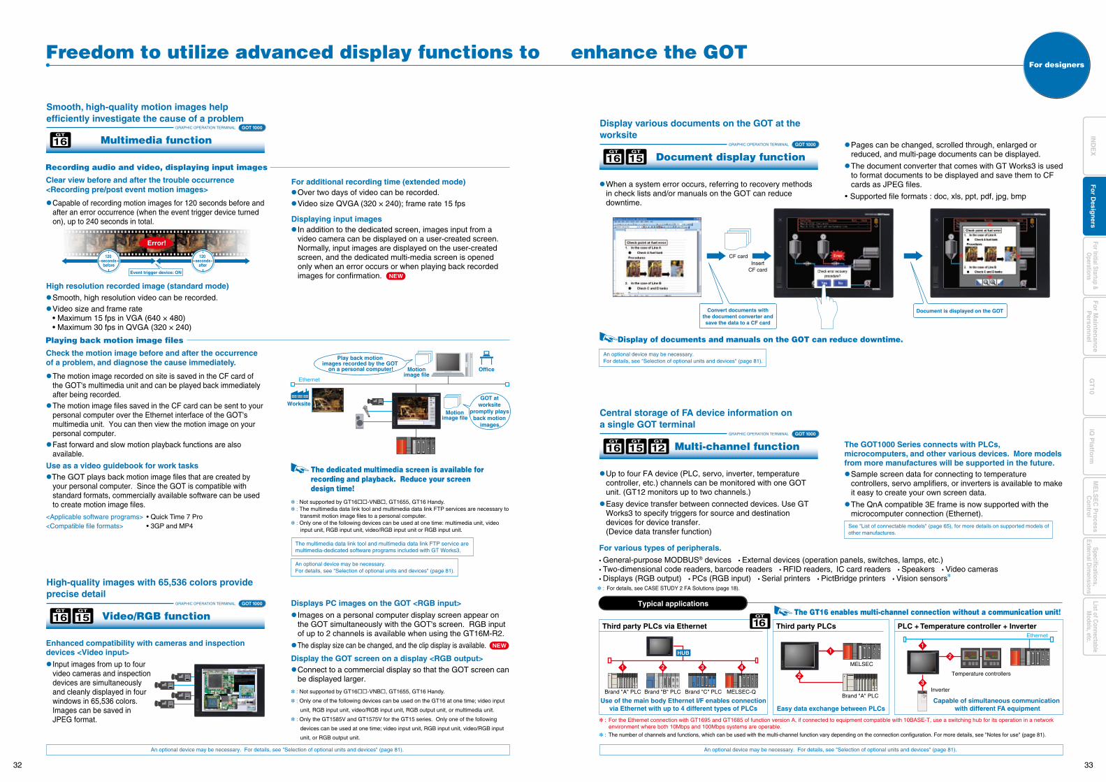
Capable of recording motion images for 120 seconds before and after an error occurrence (when the event trigger device turned on), up to 240 seconds in total.
The motion image recorded on site is saved in the CF card of the GOT's multimedia unit and can be played back immediately after being recorded. The motion image files saved in the CF card can be sent to your
personal computer over the Ethernet interface of the GOT's multimedia unit. You can then view the motion image on your personal computer. Fast forward and slow motion playback functions are also
available.
Use as a video guidebook for work tasksThe GOT plays back motion image files that are created by
your personal computer. Since the GOT is compatible with standard formats, commercially available software can be used to create motion image files.
<Applicable software programs> • Quick Time 7 Pro<Compatible file formats> • 3GP and MP4
Displays PC images on the GOT <RGB input>
Images on a personal computer display screen appear on the GOT simultaneously with the GOT's screen. RGB input of up to 2 channels is available when using the GT16M-R2.
The display size can be changed, and the clip display is available.
Display the GOT screen on a display <RGB output> Connect to a commercial display so that the GOT screen can
be displayed larger.
: Not supported by GT16-VNB, GT1655, GT16 Handy.
: Only one of the following devices can be used on the GT16 at one time; video input
unit, RGB input unit, video/RGB input unit, RGB output unit, or multimedia unit.
: Only the GT1585V and GT1575V for the GT15 series. Only one of the following
devices can be used at one time; video input unit, RGB input unit, video/RGB input
unit, or RGB output unit.
Enhanced compatibility with cameras and inspection devices <Video input>
Input images from up to four video cameras and inspection devices are simultaneously and cleanly displayed in four windows in 65,536 colors. Images can be saved in JPEG format.
Smooth, high resolution video can be recorded. Video size and frame rate • Maximum 15 fps in VGA (640 × 480) • Maximum 30 fps in QVGA (320 × 240)
When a system error occurs, referring to recovery methods in check lists and/or manuals on the GOT can reduce downtime.
Pages can be changed, scrolled through, enlarged or reduced, and multi-page documents can be displayed.
The document converter that comes with GT Works3 is used to format documents to be displayed and save them to CF cards as JPEG files.
Supported file formats : doc, xls, ppt, pdf, jpg, bmp
The GOT1000 Series connects with PLCs, microcomputers, and other various devices. More models from more manufactures will be supported in the future. Sample screen data for connecting to temperature
controllers, servo amplifiers, or inverters is available to make it easy to create your own screen data.
The QnA compatible 3E frame is now supported with the microcomputer connection (Ethernet).
Over two days of video can be recorded. Video size QVGA (320 × 240); frame rate 15 fps
In addition to the dedicated screen, images input from a video camera can be displayed on a user-created screen. Normally, input images are displayed on the user-created screen, and the dedicated multi-media screen is opened only when an error occurs or when playing back recorded images for confirmation.
: Not supported by GT16-VNB, GT1655, GT16 Handy. : The multimedia data link tool and multimedia data link FTP services are necessary to
transmit motion image files to a personal computer. : Only one of the following devices can be used at one time: multimedia unit, video
input unit, RGB input unit, video/RGB input unit or RGB input unit.
The multimedia data link tool and multimedia data link FTP service are multimedia-dedicated software programs included with GT Works3.
An optional device may be necessary.For details, see "Selection of optional units and devices" (page 81).
An optional device may be necessary.For details, see "Selection of optional units and devices" (page 81).
See "List of connectable models" (page 65), for more details on supported models of other manufactures.
Event trigger device: ON
CF cardInsert
CF card
Convert documents withthe document converter andsave the data to a CF card
Document is displayed on the GOT
Display of documents and manuals on the GOT can reduce downtime.
: For details, see CASE STUDY 2 FA Solutions (page 18).
NEW
NEW
GRAPHIC OPERATION TERMINAL
Multimedia function
Smooth, high-quality motion images help efficiently investigate the cause of a problem
GOT 1000
Freedom to utilize advanced display functions to enhance the GOT
Clear view before and after the trouble occurrence<Recording pre/post event motion images>
16GT
GRAPHIC OPERATION TERMINAL
Video/RGB function
High-quality images with 65,536 colors provide precise detail
GOT 1000
Recording audio and video, displaying input images
16GT
15GT
GRAPHIC OPERATION TERMINAL
Document display function
Display various documents on the GOT at the worksite
GOT 1000
16GT
15GT
Up to four FA device (PLC, servo, inverter, temperature controller, etc.) channels can be monitored with one GOT unit. (GT12 monitors up to two channels.)
Easy device transfer between connected devices. Use GT Works3 to specify triggers for source and destination devices for device transfer.
(Device data transfer function)
16GT
15GT
12GT
GRAPHIC OPERATION TERMINAL
Multi-channel function GOT 1000
Central storage of FA device information on a single GOT terminal
High resolution recorded image (standard mode)
For additional recording time (extended mode)
Displaying input images
The dedicated multimedia screen is available for recording and playback. Reduce your screen design time!
Check the motion image before and after the occurrence of a problem, and diagnose the cause immediately.
Playing back motion image files
For various types of peripherals.
General-purpose MODBUS® devices External devices (operation panels, switches, lamps, etc.) Two-dimensional code readers, barcode readers RFID readers, IC card readers Speakers Video cameras Displays (RGB output) PCs (RGB input) Serial printers PictBridge printers Vision sensors
: For the Ethernet connection with GT1695 and GT1685 of function version A, if connected to equipment compatible with 10BASE-T, use a switching hub for its operation in a network environment where both 10Mbps and 100Mbps systems are operable.
: The number of channels and functions, which can be used with the multi-channel function vary depending on the connection configuration. For more details, see "Notes for use" (page 81).
The GT16 enables multi-channel connection without a communication unit!Typical applications
An optional device may be necessary. For details, see "Selection of optional units and devices" (page 81).An optional device may be necessary. For details, see "Selection of optional units and devices" (page 81).
Error!
Worksite
OfficeMotionimage file
Motionimage file
GOT at worksite
promptly plays back motion
images.
Play back motion images recorded by the GOT
on a personal computer!
Ethernet
MELSEC
Brand "A" PLC
1
2
3
16GT
Inverter
Third party PLCs
Easy data exchange between PLCs
PLC + Temperature controller + Inverter
Capable of simultaneous communication with different FA equipment
Ethernet
Third party PLCs via Ethernet
Use of the main body Ethernet I/F enables connectionvia Ethernet with up to 4 different types of PLCs
2
1
1 2 3 4
Brand "A" PLC Brand "B" PLC Brand "C" PLC MELSEC-Q
HUB
Temperature controllers
120 secondsbefore
120 seconds
after
For designers
32 33
Fo
r Main
tenan
ceP
erson
nel
GT
10iQ
Platfo
rmFor Initial Startup &
Operations
Fo
r Desig
ners
IND
EX
ME
LSE
C P
rocessC
ontrolList of C
onnectableM
odels, etc.Specifications,
External Dim
ensions
Ethernet
USB mouse
No need for gateway personal computer or database transfer programs. Minimize the cost!
USB hub
USB keyboard
Use the mouse to click touch switches
Use the keyboard to enter ASCII characters and numbers
This is convenient when you need to operate small switches or enter many characters.
You can view files suchas manuals stored on your personal computer,or you can use browsersand engineering tools.
Q25HCPU QX10 QJ71BR11QX41
0123456789ABCDEF
QJ71BR11QX41
PC screen
Worksite Office
PC screen
Operation from mouse/keyboard
Display on the PC screen
: Not supported by the GT16 Handy.
GOT transmits data collectively also to the equipment of other manufacturers.
See "GT SoftGOT1000" (page 27), for more details.
An optional device may be necessary. For details, see "Selection of optional units and devices" (page 81).
GRAPHIC OPERATION TERMINAL GOT 1000 GRAPHIC OPERATION TERMINAL GOT 1000
GRAPHIC OPERATION TERMINAL GOT 1000
GRAPHIC OPERATION TERMINAL GOT 1000
GRAPHIC OPERATION TERMINAL GOT 1000
USB mouse
USB hub
USB keyboard
Ethernet
SQL statement
MELSECBrand "A" PLC Temperature controller
MESdatabase
server
MES application +
database
Worksite
Office
Mitsubishi Electric e-F@ctory presents the appropriate products to connect production information and MES (manufacturing execution system) to improve productivity of clients' plants.
• DB link function (tag function / trigger buffering function / trigger monitor function / SQL statement transmission function <SELECT / SELECT multiple data / UPDATE / INSERT> / calculation processing function / program execution function / DB buffering function)
• SNTP time synchronization function• Resource data transmission function • Diagnosis function• DB server function (ODBC connection function / connection setting function / log output function)
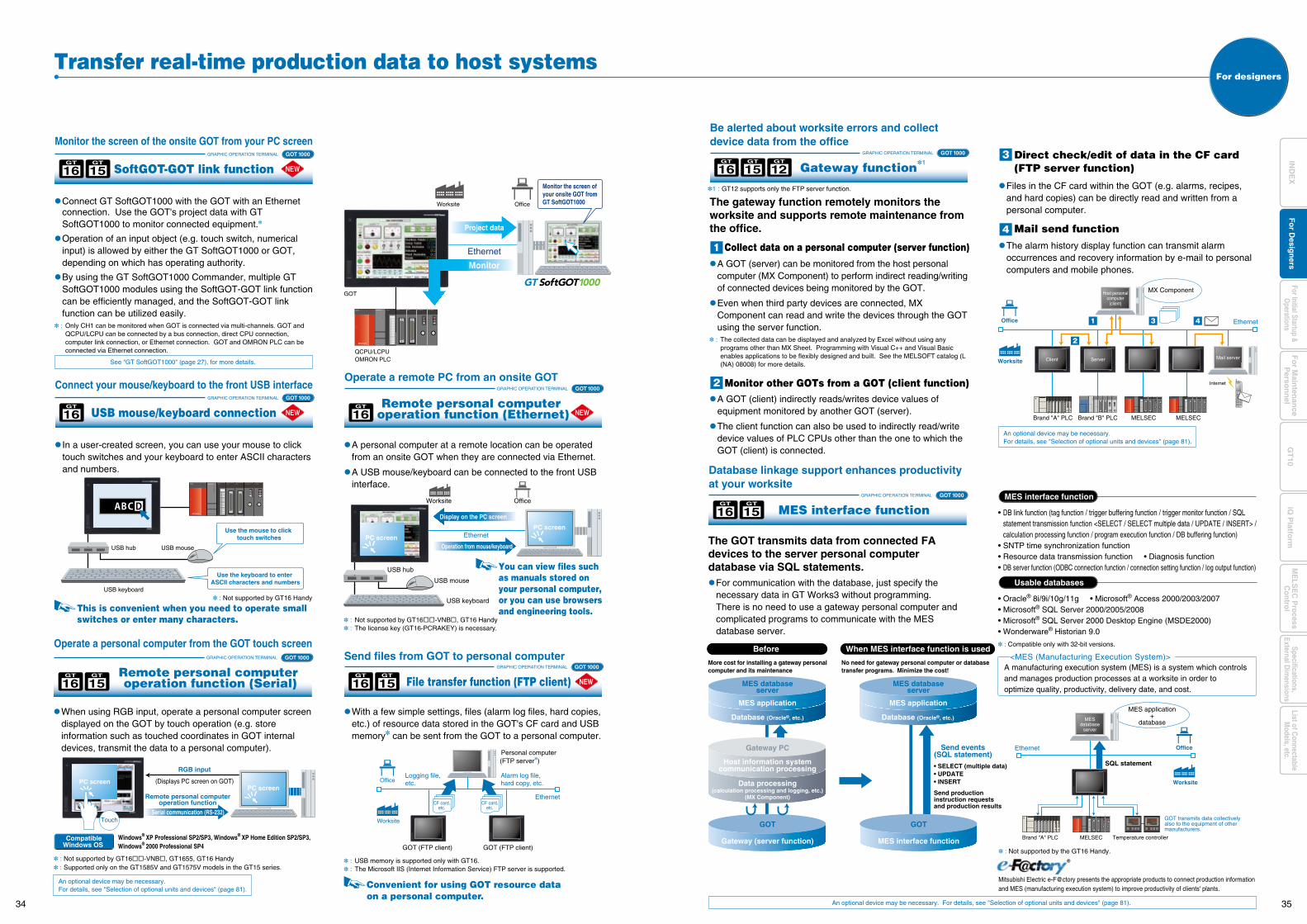
MES interface function
• Oracle® 8i/9i/10g/11g • Microsoft® Access 2000/2003/2007• Microsoft® SQL Server 2000/2005/2008• Microsoft® SQL Server 2000 Desktop Engine (MSDE2000)• Wonderware® Historian 9.0
Usable databases
<MES (Manufacturing Execution System)>A manufacturing execution system (MES) is a system which controls and manages production processes at a worksite in order to optimize quality, productivity, delivery date, and cost.
: Compatible only with 32-bit versions.
: Not supported by GT16 Handy
Ethernet
Convenient for using GOT resource dataon a personal computer.
GRAPHIC OPERATION TERMINAL
File transfer function (FTP client)
Send files from GOT to personal computerGOT 1000
16GT
15GT
NEW
Worksite
Office
GOT (FTP client)
Personal computer(FTP server)
Alarm log file,hard copy, etc.
Logging file,etc.
GOT (FTP client)
CF card,etc.
CF card,etc.
Ethernet
Worksite
GOT
QCPU/LCPUOMRON PLC
Office
Project data
Q25HCPU QX10 QJ71BR11QX41
0123456789ABCDEF
QJ71BR11QX41
Monitor
Monitor the screen ofyour onsite GOT fromGT SoftGOT1000 Connect GT SoftGOT1000 with the GOT with an Ethernet
connection. Use the GOT's project data with GT SoftGOT1000 to monitor connected equipment.
Operation of an input object (e.g. touch switch, numerical input) is allowed by either the GT SoftGOT1000 or GOT, depending on which has operating authority.
By using the GT SoftGOT1000 Commander, multiple GT SoftGOT1000 modules using the SoftGOT-GOT link function can be efficiently managed, and the SoftGOT-GOT link function can be utilized easily.
: Only CH1 can be monitored when GOT is connected via multi-channels. GOT and QCPU/LCPU can be connected by a bus connection, direct CPU connection, computer link connection, or Ethernet connection. GOT and OMRON PLC can be connected via Ethernet connection.
A GOT (server) can be monitored from the host personal computer (MX Component) to perform indirect reading/writing of connected devices being monitored by the GOT.
Even when third party devices are connected, MX Component can read and write the devices through the GOT using the server function.
: The collected data can be displayed and analyzed by Excel without using any programs other than MX Sheet. Programming with Visual C++ and Visual Basic enables applications to be flexibly designed and built. See the MELSOFT catalog (L (NA) 08008) for more details.
: Not supported by GT16-VNB, GT16 Handy : The license key (GT16-PCRAKEY) is necessary.
: USB memory is supported only with GT16. : The Microsoft IIS (Internet Information Service) FTP server is supported.
A GOT (client) indirectly reads/writes device values of equipment monitored by another GOT (server).
The client function can also be used to indirectly read/write device values of PLC CPUs other than the one to which the GOT (client) is connected.
Transfer real-time production data to host systems
SoftGOT-GOT link function
Monitor the screen of the onsite GOT from your PC screen
16GT
15GT
For designers
Gateway function
Be alerted about worksite errors and collect device data from the office
In a user-created screen, you can use your mouse to click touch switches and your keyboard to enter ASCII characters and numbers.
USB mouse/keyboard connection
Connect your mouse/keyboard to the front USB interface
16GT
A personal computer at a remote location can be operated from an onsite GOT when they are connected via Ethernet.
A USB mouse/keyboard can be connected to the front USB interface.
Remote personal computer operation function (Ethernet)
Operate a remote PC from an onsite GOT
16GT
Ethernet
Collect data on a personal computer (server function)
Direct check/edit of data in the CF card(FTP server function)
Mail send function
The gateway function remotely monitors the worksite and supports remote maintenance from the office.
MES interface function
Database linkage support enhances productivity at your worksite
16GT
15GT
Brand "A" PLC Brand "B" PLC MELSEC MELSEC
Mail server
Internet
Host personalcomputer
(client)
MX Component
Worksite
Office
Client Server
Monitor other GOTs from a GOT (client function)
The alarm history display function can transmit alarm occurrences and recovery information by e-mail to personal computers and mobile phones.
Files in the CF card within the GOT (e.g. alarms, recipes, and hard copies) can be directly read and written from a personal computer.
The GOT transmits data from connected FA devices to the server personal computer database via SQL statements. For communication with the database, just specify the
necessary data in GT Works3 without programming. There is no need to use a gateway personal computer and
complicated programs to communicate with the MES database server.
An optional device may be necessary. For details, see "Selection of optional units and devices" (page 81).
More cost for installing a gateway personal computer and its maintenance
Before When MES interface function is used
MES databaseserver
MES application
Database (Oracle®, etc.) Database (Oracle®, etc.)
MES databaseserver
MES application
GOT
Gateway (server function)
Host information systemcommunication processing
Gateway PC
Data processing(calculation processing and logging, etc.)
(MX Component)
Send events(SQL statement)
Send production instruction requests and production results
• SELECT (multiple data)• UPDATE• INSERT
GOT
MES interface function
An optional device may be necessary. For details, see "Selection of optional units and devices" (page 81).
GRAPHIC OPERATION TERMINAL GOT 1000
Remote personal computer operation function (Serial)
Operate a personal computer from the GOT touch screen
16GT
15GT
When using RGB input, operate a personal computer screen displayed on the GOT by touch operation (e.g. store information such as touched coordinates in GOT internal devices, transmit the data to a personal computer).
With a few simple settings, files (alarm log files, hard copies, etc.) of resource data stored in the GOT's CF card and USB memory can be sent from the GOT to a personal computer.
PC screenPC screen
RGB input
(Displays PC screen on GOT)
Serial communication (RS-232)
Remote personal computeroperation function
Touch
Windows® XP Professional SP2/SP3, Windows® XP Home Edition SP2/SP3, Windows® 2000 Professional SP4
: Not supported by GT16-VNB, GT1655, GT16 Handy : Supported only on the GT1585V and GT1575V models in the GT15 series.
CompatibleWindows OS
16GT
15GT
12GT
1 : GT12 supports only the FTP server function.
1
34 35
Fo
r Main
tenan
ceP
erson
nel
GT
10iQ
Platfo
rmFor Initial Startup &
Operations
Fo
r Desig
ners
IND
EX
ME
LSE
C P
rocessC
ontrolList of C
onnectableM
odels, etc.Specifications,
External Dim
ensions
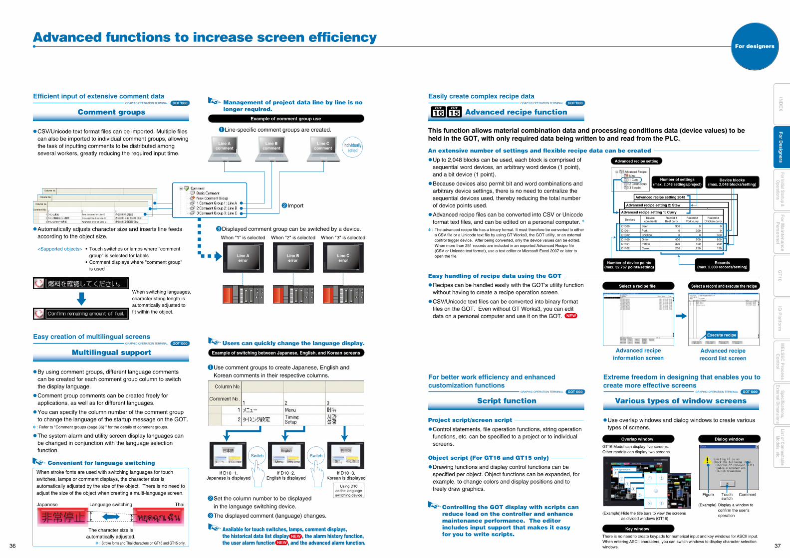
Advanced recipe setting 2048
Advanced recipe setting 2: Stew
Advanced recipe setting 1: Curry
D1000
D1001
D1002
D1100
D1101
D1102
Beef
Pork
Chicken
Onion
Potato
Carrot
Record 1Beef curry
Record 2Pork curry
Record 3Chicken curry
300
0
0
400
300
200
0
300
0
500
400
250
0
0
300
600
200
150
Device commentsDevices
Various types of window screens
Extreme freedom in designing that enables you to create more effective screens
GT16 Model can display five screens. Other models can display two screens.
(Example) Hide the title bars to view the screens as divided windows (GT16)
(Example) Display a window to confirm the user's operation
Overlap window
There is no need to create keypads for numerical input and key windows for ASCII input.When entering ASCII characters, you can switch windows to display character selection windows.
Key window
Dialog window
Records(max. 2,000 records/setting)
Number of device points(max. 32,767 points/setting)
Number of settings(max. 2,048 settings/project)
Japanese ThaiLanguage switching
The character size isautomatically adjusted.
Convenient for language switching
When stroke fonts are used with switching languages for touch switches, lamps or comment displays, the character size is automatically adjusted by the size of the object. There is no need to adjust the size of the object when creating a multi-language screen.
: Stroke fonts and Thai characters on GT16 and GT15 only.
Device blocks(max. 2,048 blocks/setting)
Figure Touchswitch
Comment
GRAPHIC OPERATION TERMINAL GOT 1000
CSV/Unicode text format files can be imported. Multiple files can also be imported to individual comment groups, allowing the task of inputting comments to be distributed among several workers, greatly reducing the required input time. An extensive number of settings and flexible recipe data can be created
Up to 2,048 blocks can be used, each block is comprised of sequential word devices, an arbitrary word device (1 point), and a bit device (1 point).
Because devices also permit bit and word combinations and arbitrary device settings, there is no need to centralize the sequential devices used, thereby reducing the total number of device points used.
Advanced recipe files can be converted into CSV or Unicode format text files, and can be edited on a personal computer.
: The advanced recipe file has a binary format. It must therefore be converted to either a CSV file or a Unicode text file by using GT Works3, the GOT utility, or an external control trigger device. After being converted, only the device values can be edited. When more than 251 records are included in an exported Advanced Recipe file (CSV or Unicode text format), use a text editor or Microsoft Excel 2007 or later to open the file.
Easy handling of recipe data using the GOT
Recipes can be handled easily with the GOT's utility function without having to create a recipe operation screen.
CSV/Unicode text files can be converted into binary format files on the GOT. Even without GT Works3, you can edit data on a personal computer and use it on the GOT.
Project script/screen script
Control statements, file operation functions, string operation functions, etc. can be specified to a project or to individual screens.
Object script (For GT16 and GT15 only)
Drawing functions and display control functions can be specified per object. Object functions can be expanded, for example, to change colors and display positions and to freely draw graphics.
Use overlap windows and dialog windows to create various types of screens.
Automatically adjusts character size and inserts line feeds according to the object size.
<Supported objects> • Touch switches or lamps where "comment group" is selected for labels
• Comment displays where "comment group" is used
Advanced functions to increase screen efficiency
Comment groups
Efficient input of extensive comment data
GRAPHIC OPERATION TERMINAL GOT 1000
Script function
For better work efficiency and enhancedcustomization functions
GRAPHIC OPERATION TERMINAL GOT 1000
GRAPHIC OPERATION TERMINAL GOT 1000
By using comment groups, different language comments can be created for each comment group column to switch the display language.
Comment group comments can be created freely for applications, as well as for different languages.
You can specify the column number of the comment group to change the language of the startup message on the GOT.
: Refer to "Comment groups (page 36) " for the details of comment groups.
The system alarm and utility screen display languages can be changed in conjunction with the language selection function.
Multilingual support
Easy creation of multilingual screens
When switching languages, character string length is automatically adjusted to fit within the object.
Example of switching between Japanese, English, and Korean screens
Users can quickly change the language display.
Switch Switch
If D10=1,Japanese is displayed
If D10=2,English is displayed
If D10=3,Korean is displayed
Using D10as the languageswitching device
Available for touch switches, lamps, comment displays,the historical data list display , the alarm history function,the user alarm function , and the advanced alarm function.
Controlling the GOT display with scripts can reduce load on the controller and enhance maintenance performance. The editor includes input support that makes it easy for you to write scripts.
Use comment groups to create Japanese, English and Korean comments in their respective columns.
Set the column number to be displayed in the language switching device.
The displayed comment (language) changes.
For designers
GRAPHIC OPERATION TERMINAL GOT 1000
Advanced recipe function
Easily create complex recipe data
16GT
15GT
This function allows material combination data and processing conditions data (device values) to be held in the GOT, with only required data being written to and read from the PLC.
When "1" is selected
Individuallyedited
Example of comment group use
Line Aerror
When "3" is selectedWhen "2" is selected
Management of project data line by line is no longer required.
Line Acomment
Line Bcomment
Line Ccomment
Line Berror
Line Cerror
Line-specific comment groups are created.
Import
Displayed comment group can be switched by a device.
Advanced recipe setting
Select a recipe file Select a record and execute the recipe
Execute recipe
Advanced recipeinformation screen
Advanced reciperecord list screen
Overlap window
q
w
e
r
t
q w
r
e
t
36 37
Fo
r Main
tenan
ceP
erson
nel
GT
10iQ
Platfo
rmFor Initial Startup &
Operations
Fo
r Desig
ners
IND
EX
ME
LSE
C P
rocessC
ontrolList of C
onnectableM
odels, etc.Specifications,
External Dim
ensions
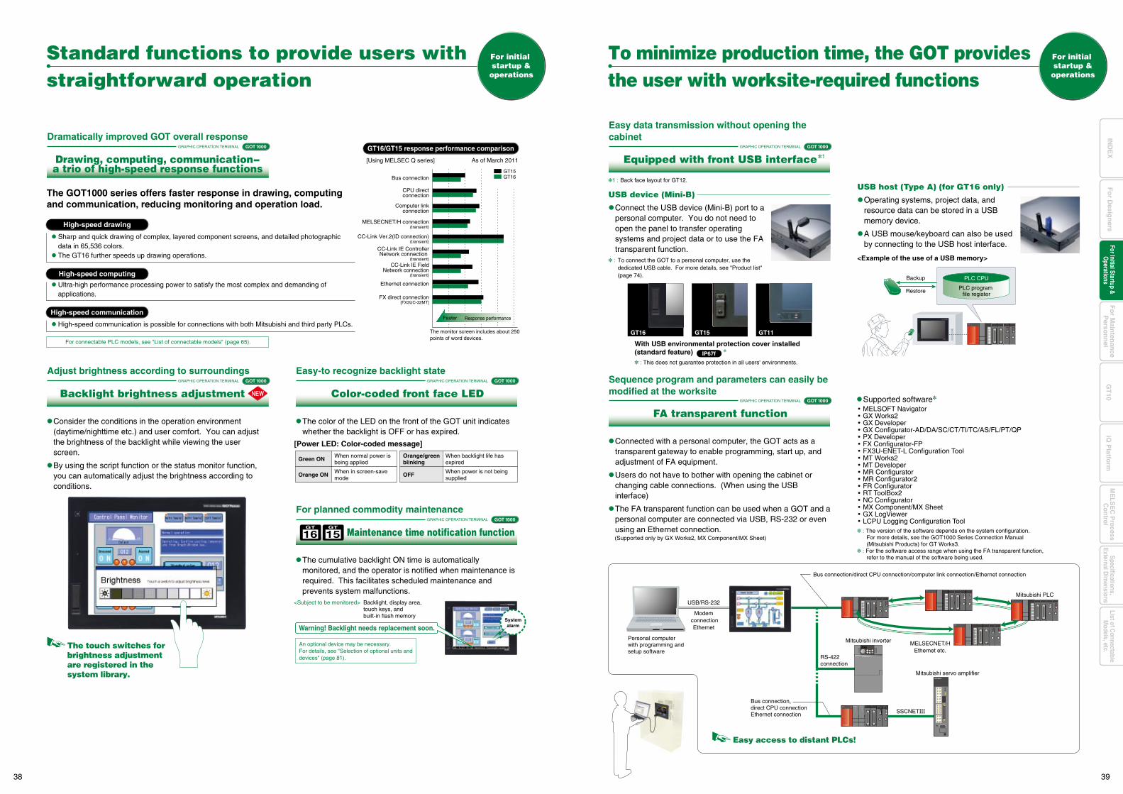
GT15 GT11GT16
: This does not guarantee protection in all users' environments.
IP67f
With USB environmental protection cover installed(standard feature)
Easy data transmission without opening the cabinet
[Power LED: Color-coded message]
16GT
15GT
Backup
Restore PLC program file register
PLC CPU
: The version of the software depends on the system configuration. For more details, see the GOT1000 Series Connection Manual
(Mitsubishi Products) for GT Works3. : For the software access range when using the FA transparent function, refer to the manual of the software being used.
Supported software
Modem connection
Ethernet
MELSOFT Navigator GX Works2 GX Developer GX Configurator-AD/DA/SC/CT/TI/TC/AS/FL/PT/QP PX Developer FX Configurator-FP FX3U-ENET-L Configuration Tool MT Works2 MT Developer MR Configurator MR Configurator2 FR Configurator RT ToolBox2 NC Configurator MX Component/MX Sheet GX LogViewer LCPU Logging Configuration Tool
MELSECNET/HEthernet etc.
Personal computer with programming and setup software
Bus connection/direct CPU connection/computer link connection/Ethernet connection
RS-422 connection
Mitsubishi inverter
Mitsubishi servo amplifier
SSCNETIII
Mitsubishi PLCUSB/RS-232
Bus connection, direct CPU connectionEthernet connection
Easy access to distant PLCs!
Standard functions to provide users with straightforward operation
For initial startup &operations
For initial startup &operations
To minimize production time, the GOT providesthe user with worksite-required functions
High-speed drawing
High-speed communication
High-speed computing
GRAPHIC OPERATION TERMINAL
The GOT1000 series offers faster response in drawing, computing and communication, reducing monitoring and operation load.
Drawing, computing, communication-a trio of high-speed response functions
Dramatically improved GOT overall response
GRAPHIC OPERATION TERMINAL
Backlight brightness adjustment
Adjust brightness according to surroundings
GRAPHIC OPERATION TERMINAL
Equipped with front USB interface
Sequence program and parameters can easily be modified at the worksite
GRAPHIC OPERATION TERMINAL
FA transparent function
GRAPHIC OPERATION TERMINAL
Color-coded front face LED
Easy-to recognize backlight state
GRAPHIC OPERATION TERMINAL
Maintenance time notification function
For planned commodity maintenance
Sharp and quick drawing of complex, layered component screens, and detailed photographic data in 65,536 colors.
The GT16 further speeds up drawing operations.
Ultra-high performance processing power to satisfy the most complex and demanding of applications.
High-speed communication is possible for connections with both Mitsubishi and third party PLCs.
The touch switches for brightness adjustment are registered in the system library.
Green ON When normal power is being applied
Orange/greenblinking
When backlight life has expired
Orange ON When in screen-save mode
OFF When power is not being supplied
<Subject to be monitored> Backlight, display area, touch keys, and built-in flash memory
Warning! Backlight needs replacement soon.Systemalarm
An optional device may be necessary.For details, see "Selection of optional units anddevices" (page 81).
GOT 1000
GOT 1000
GOT 1000
For connectable PLC models, see "List of connectable models" (page 65).
Consider the conditions in the operation environment (daytime/nighttime etc.) and user comfort. You can adjust the brightness of the backlight while viewing the user screen.
By using the script function or the status monitor function, you can automatically adjust the brightness according to conditions.
USB device (Mini-B)
Connect the USB device (Mini-B) port to a personal computer. You do not need to open the panel to transfer operating systems and project data or to use the FA transparent function.
: To connect the GOT to a personal computer, use the dedicated USB cable. For more details, see "Product list" (page 74).
USB host (Type A) (for GT16 only)
Operating systems, project data, and resource data can be stored in a USB memory device.
A USB mouse/keyboard can also be used by connecting to the USB host interface.
<Example of the use of a USB memory>
Connected with a personal computer, the GOT acts as a transparent gateway to enable programming, start up, and adjustment of FA equipment.
Users do not have to bother with opening the cabinet or changing cable connections. (When using the USB interface)
The FA transparent function can be used when a GOT and a personal computer are connected via USB, RS-232 or even using an Ethernet connection.
The color of the LED on the front of the GOT unit indicates whether the backlight is OFF or has expired.
The cumulative backlight ON time is automatically monitored, and the operator is notified when maintenance is required. This facilitates scheduled maintenance and prevents system malfunctions.
1 : Back face layout for GT12.
1
(Supported only by GX Works2, MX Component/MX Sheet)
CC-Link IE FieldNetwork connection
(transient)
GT16/GT15 response performance comparison
[Using MELSEC Q series] As of March 2011
The monitor screen includes about 250 points of word devices.
Bus connection
CPU directconnection
Computer linkconnection
GT15GT16
MELSECNET/H connection(transient)
CC-Link Ver.2(ID connection)(transient)
CC-Link IE Controller Network connection
(transient)
Ethernet connection
FX direct connection[FX3UC-32MT]
Faster Response performance
GOT 1000
GOT 1000 GOT 1000
38 39
Fo
r Main
tenan
ceP
erson
nel
GT
10iQ
Platfo
rmFor Initial Startup &
Operations
Fo
r Desig
ners
Specifications,External D
imensions
ME
LSE
C P
rocessC
ontrolList of C
onnectableM
odels, etc.IN
DE
X
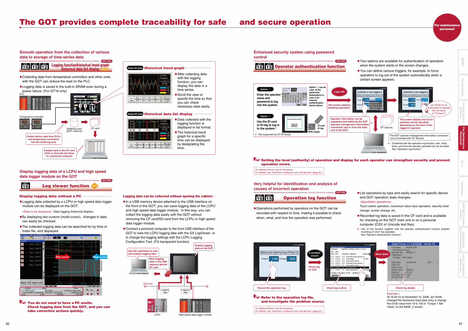
For maintenancepersonnel
LCPU High-speed data logger module
Logging data
Logging data
Collect device data from PLCsand temperature controllers
into the buffering area
Q25HCPU QX10 QJ71BR11QX41
0123456789ABCDEF
QJ71BR11QX41
Ethernet
Display logging data on the GOT
Save logging data in the USB memory device/CF card
Use GX LogViewer to view and analyze logging data
: Combined with the operation log function, who, what, when, and how the operator operated can be recorded. See "Operation log function."
CF card etc.
The screen appears,enabling operation!
Login OK
Setting the level (authority) of operation and display for each operator can strengthen security and prevent operation errors.
RFID reader
ID cardID tag
Option q
The GOT operator management information conversion tool is included with GT Works3.
Operator information can be registered and edited by the GOT operator management information conversion tool or from the main unit of the GOT.
You do not need to have a PC onsite. Check logging data from the GOT, and you can take corrective actions quickly.
: Not supported by GT16 Handy
16GT
15GT
16GT
15GT
16GT
An optional device may be necessary.For details, see "Selection of optional units and devices" (page 81).
Enter the operator name and password to log into the system.
Option w can be used at the same time. Redundancy in case of an external authentication device failure.
Use the ID card or ID tag to log in to the system.
Setting screw tightening torque (Product A)
Torque1 Torque2
Operation Log Data List
File Name
A.D.
Date Time Screen No.
Touch switch: Screen switching
Time setting
Touch switch: Bit set
Touch switch: Screen switching
Touch switch: Bit set
Switch applications
Numerical Input
Ladder monitor
Operation Change To
Torque 1 set value JonSmith
SearchSearchDate(descending)
Function Numerical inputScreen No.Operation Torque 1 set value
OperatorUser IDAction NoData TypeDeviceChange ToChng From
:NUM_VAL
:BASE_2:
:JonSmith (ID:1 ):–:1:BIN16:D100:100:10
Date/Time:11/14/2008 16:43:10
A problemoccurs
Refer to the operation log file, and investigate the problem source.
An optional device may be necessary.For details, see "Selection of optional units and devices" (page 81).
Record the operation log Check log outline Check log details
Check log on GOT
Example )At 16:43:10 on November 14, 2008, Jon Smith changed the Numerical Input data entry to change the D100 value from 10 to 100 in "Torque 1 Set Value" on the BASE_2 screen.
More detailRed cursor Blue cursor
Option w
GRAPHIC OPERATION TERMINAL GOT 1000
The GOT provides complete traceability for safe and secure operation
Logging function/historical trend graph/historical data list display
Smooth operation from the collection of various data to storage of time-series data
GRAPHIC OPERATION TERMINAL GOT 1000
Operator authentication function
Enhanced security system using password control
GRAPHIC OPERATION TERMINAL GOT 1000
Operation log function
Very helpful for identification and analysis of causes of incorrect operation
Collecting data from temperature controllers and other units with the GOT can reduce the load on the PLC.
Logging data is saved in the built-in SRAM even during a power failure. (For GT16 only)
Operations performed by operators on the GOT can be recorded with respect to time, making it possible to check when, what, and how the operation was performed.
Two options are available for authentication of operators when the system starts or the screen changes.
You can define various triggers, for example, to force operators to log out of the system automatically when a certain screen appears.
GRAPHIC OPERATION TERMINAL GOT 1000
Log viewer function
Display logging data of a LCPU and high speed data logger module on the GOT
Display logging data without a PC
Logging data collected by a LCPU or high speed data logger module can be displayed on the GOT.
<Data to be displayed> Data logging (historical display)
By displaying two cursors (multi-cursor), changes in data can easily be checked.
The collected logging data can be searched for by time or index No. and displayed.
List operations by type and easily search for specific device and GOT operation state changes.
<Specifiable operations>
Touch switch operation, numerical value input operation, security level
change, screen change, etc.
Recorded log data is saved in the CF card and is available for checking on the GOT main unit or on a personal computer (CSV or Unicode text files).
: Use of this function together with the operator authentication function enables recording of "who" has operated.
See "Operator authentication function".
Logging data can be collected without opening the cabinet
In a USB memory device attached to the USB interface on the front of the GOT, you can save logging data of the LCPU and high speed data logger module. In this way, you can collect the logging data easily with the GOT without removing the CF card/SD card from the LCPU or high speed data logger module.
Connect a personal computer to the front USB interface of the GOT to view the LCPU logging data with the GX LogViewer, or to change the logging settings with the LCPU Logging Configuration Tool. (FA transparent function)
Q25HCPU QX10 QJ71BR11QX41
0123456789ABCDEF
QJ71BR11QX41
PLC
Temperature controller
Buffering area(GOT memory)
CF card
Analyze data in the CF card(CSV or Unicode text files)
on a personal computer
Display with graphs Historical trend graph
Display with values Historical data list display
After collecting data with the logging function, you can display the data in a time series.
Scroll the view or specify the time so that you can check necessary data easily.
Data collected with the logging function is displayed in list format.
The historical trend graph for a specific time can be displayed by designating the time.
JonSmith is now logged-in
Setting screw tightening torque (Product A)
Torque1
Torque2
Torque3
JonSmith is now logged-in
Setting screw tightening torque (Product A)
Torque1
Torque2
Torque3
Changeoperator
Changeoperator
Perform authentication operation.
Jon Smith is not authorized to change
the set value of "Torque 3".
The screen display and touch switches can be specified depending on the level of the logged-in operator.
16GT
15GT
12GT
40 41
Fo
r Main
tenan
ceP
erson
nel
GT
10iQ
Platfo
rmFor Initial Startup &
Operations
Fo
r Desig
ners
Specifications,External D
imensions
ME
LSE
C P
rocessC
ontrolList of C
onnectableM
odels, etc.IN
DE
X
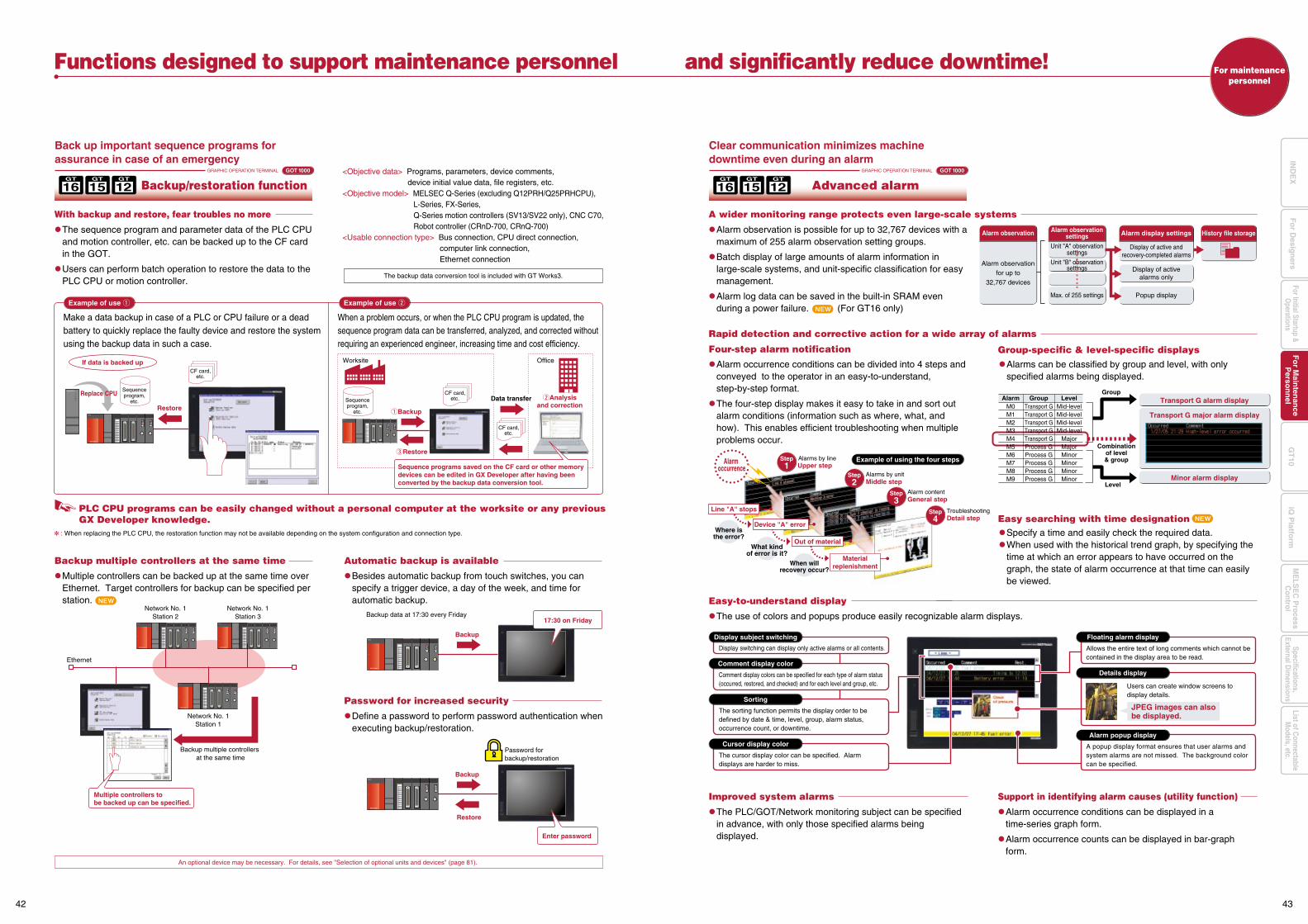
<Objective data> Programs, parameters, device comments, device initial value data, file registers, etc.
<Objective model> MELSEC Q-Series (excluding Q12PRH/Q25PRHCPU),L-Series, FX-Series, Q-Series motion controllers (SV13/SV22 only), CNC C70, Robot controller (CRnD-700, CRnQ-700)
<Usable connection type> Bus connection, CPU direct connection, computer link connection, Ethernet connection
Backup data at 17:30 every Friday
Password for backup/restoration
Restore
Backup
Ethernet
Network No. 1Station 1
Backup multiple controllers at the same time
Network No. 1Station 2
Network No. 1Station 3
Multiple controllers to be backed up can be specified.
Backup
17:30 on Friday
Enter password
An optional device may be necessary. For details, see "Selection of optional units and devices" (page 81).
Group-specific & level-specific displays
For maintenancepersonnel
Functions designed to support maintenance personnel and significantly reduce downtime!
GRAPHIC OPERATION TERMINAL GOT 1000
Back up important sequence programs for assurance in case of an emergency
With backup and restore, fear troubles no more
The sequence program and parameter data of the PLC CPU and motion controller, etc. can be backed up to the CF card in the GOT.
Users can perform batch operation to restore the data to the PLC CPU or motion controller.
Backup multiple controllers at the same time
Multiple controllers can be backed up at the same time over Ethernet. Target controllers for backup can be specified per station.
Improved system alarms
The PLC/GOT/Network monitoring subject can be specified in advance, with only those specified alarms being displayed.
Support in identifying alarm causes (utility function)
Alarm occurrence conditions can be displayed in a time-series graph form.
Alarm occurrence counts can be displayed in bar-graph form.
Automatic backup is available
Besides automatic backup from touch switches, you can specify a trigger device, a day of the week, and time for automatic backup.
Password for increased security
Define a password to perform password authentication when executing backup/restoration.
The backup data conversion tool is included with GT Works3.
Backup/restoration functionGRAPHIC OPERATION TERMINAL GOT 1000
Clear communication minimizes machine downtime even during an alarm
Alarm observation is possible for up to 32,767 devices with a maximum of 255 alarm observation setting groups.
Batch display of large amounts of alarm information in large-scale systems, and unit-specific classification for easy management.
Alarm log data can be saved in the built-in SRAM even during a power failure. (For GT16 only)
A wider monitoring range protects even large-scale systems
The use of colors and popups produce easily recognizable alarm displays.
Alarm occurrence conditions can be divided into 4 steps and conveyed to the operator in an easy-to-understand, step-by-step format.
The four-step display makes it easy to take in and sort out alarm conditions (information such as where, what, and how). This enables efficient troubleshooting when multiple problems occur.
Alarms can be classified by group and level, with only specified alarms being displayed.
Specify a time and easily check the required data. When used with the historical trend graph, by specifying the
time at which an error appears to have occurred on the graph, the state of alarm occurrence at that time can easily be viewed.
Rapid detection and corrective action for a wide array of alarms
Four-step alarm notification
Advanced alarm
: When replacing the PLC CPU, the restoration function may not be available depending on the system configuration and connection type.
PLC CPU programs can be easily changed without a personal computer at the worksite or any previous GX Developer knowledge.
Make a data backup in case of a PLC or CPU failure or a dead battery to quickly replace the faulty device and restore the system using the backup data in such a case.
Q25HCPU
Example of use q
When a problem occurs, or when the PLC CPU program is updated, the sequence program data can be transferred, analyzed, and corrected without requiring an experienced engineer, increasing time and cost efficiency.
Example of use w
Sequence programs saved on the CF card or other memory devices can be edited in GX Developer after having been converted by the backup data conversion tool.
CF card,etc.
CF card,etc.
CF card,etc.
Sequenceprogram,
etc. Sequenceprogram,
etc.Restore
wAnalysisand correction
eRestore
qBackup
Replace CPU
If data is backed up OfficeWorksite
Data transfer
Alarm observationfor up to
32,767 devices
Display of active andrecovery-completed alarms
Display of activealarms only
Popup display
Unit "A" observationsettings
Max. of 255 settings
Alarm observationsettings
Unit "B" observationsettings
Alarm observation Alarm display settings History file storage
Group
Level
Combinationof level& group
M0M1M2M3M4M5M6M7M8M9
Transport GTransport GTransport GTransport GTransport GProcess GProcess GProcess GProcess GProcess G
Mid-levelMid-levelMid-levelMid-level
MajorMajorMinorMinorMinorMinor
Alarm Group Level Transport G alarm display
Minor alarm display
Transport G major alarm display
Alarm occurrence
Device "A" error
Out of material
Line "A" stops
Where isthe error?
What kindof error is it?
When willrecovery occur?
Upper stepAlarms by lineStep
1Alarms by unitMiddle step
Step2
Alarm contentGeneral step
Troubleshooting
Step3
Detail stepStep4
Example of using the four steps
Materialreplenishment
Easy-to-understand display
Display switching can display only active alarms or all contents.
Display subject switching
Comment display colors can be specified for each type of alarm status (occurred, restored, and checked) and for each level and group, etc.
Comment display color
The sorting function permits the display order to be defined by date & time, level, group, alarm status, occurrence count, or downtime.
Sorting
Allows the entire text of long comments which cannot be contained in the display area to be read.
Users can create window screens to display details.
A popup display format ensures that user alarms and system alarms are not missed. The background color can be specified.
Floating alarm display
Details display
Alarm popup display
The cursor display color can be specified. Alarm displays are harder to miss.
Cursor display color
JPEG images can also be displayed.
16GT
15GT
12GT
Easy searching with time designation
16GT
15GT
12GT
42 43
Fo
r Main
tenan
ceP
erson
nel
GT
10iQ
Platfo
rmFor Initial Startup &
Operations
Fo
r Desig
ners
Specifications,External D
imensions
ME
LSE
C P
rocessC
ontrolList of C
onnectableM
odels, etc.IN
DE
X
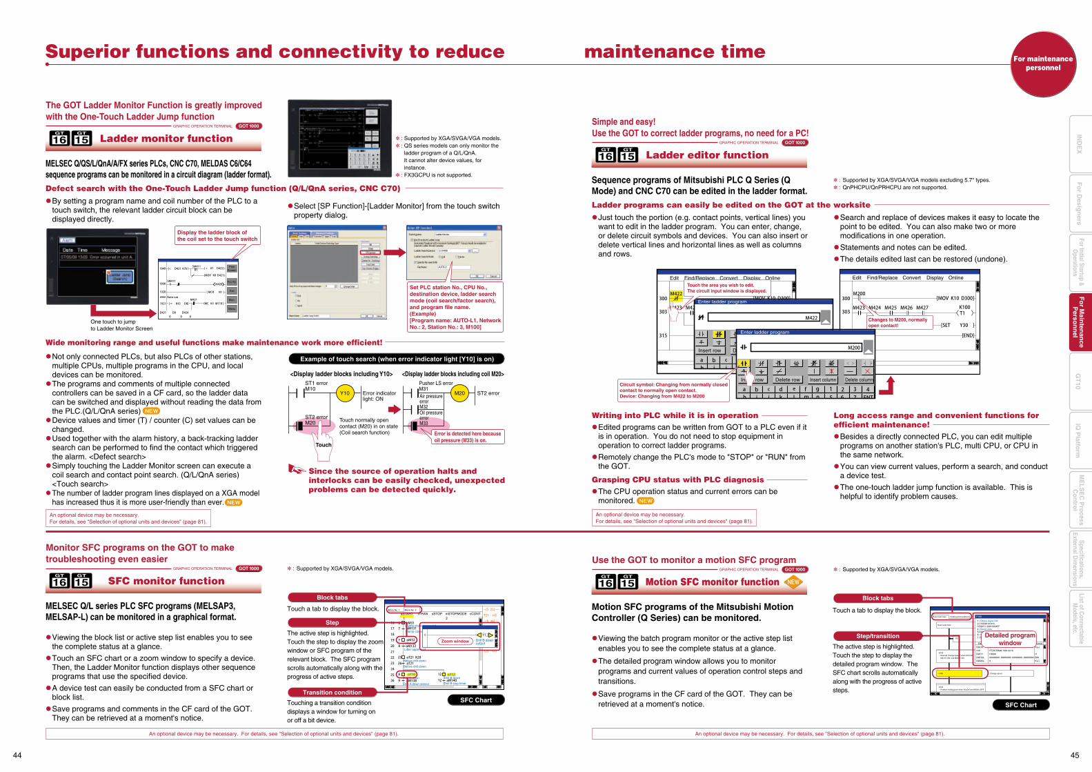
G102Position holding point when X0=ON and M2001=OFF.
G100Execute “change speed” when X19=ON, M2415=ON, and M2345=ON.
F100
P0
Change speed
1 //Obtain digital SW2 DIND2010,X103 D2011=D2010&HFF4 //Select data5 D2012L=BIN(D2011)6 //07 D2020L=D2012K1000L
Device Value Format
D2010
X10
D2011
D2012L
D2020L
0
FEDC BA98 7654 3210
H0000
00000000 00000000 00000000 00000000
0
K(±)
H
BIN
K(+)
F100Real mode main
Real mode main
Holding point positioning
Block No. 1 Block No. 2
aSTART tTRAN
Clamp close command
mSTOPMODE cCONTsSTOP
Clamp close end
Lifter up
Lifter upper end
Before drill down
Before drill down
Drill A down
Drill A down sensor
Drill B down
Drill B stop timer
Drill B down outputZoom window
SFC ChartSFC Chart
Block tabs
An optional device may be necessary. For details, see "Selection of optional units and devices" (page 81). An optional device may be necessary. For details, see "Selection of optional units and devices" (page 81).
16GT
15GT
Superior functions and connectivity to reduce maintenance time
GRAPHIC OPERATION TERMINAL GOT 1000
The GOT Ladder Monitor Function is greatly improved with the One-Touch Ladder Jump function
GRAPHIC OPERATION TERMINAL GOT 1000
MELSEC Q/QS/L/QnA/A/FX series PLCs, CNC C70, MELDAS C6/C64 sequence programs can be monitored in a circuit diagram (ladder format).
Viewing the block list or active step list enables you to see the complete status at a glance.
Touch an SFC chart or a zoom window to specify a device. Then, the Ladder Monitor function displays other sequence programs that use the specified device.
A device test can easily be conducted from a SFC chart or block list.
Save programs and comments in the CF card of the GOT. They can be retrieved at a moment's notice.
Select [SP Function]-[Ladder Monitor] from the touch switch property dialog.
Ladder monitor function
16GT
15GT
GRAPHIC OPERATION TERMINAL GOT 1000
Monitor SFC programs on the GOT to make troubleshooting even easier
MELSEC Q/L series PLC SFC programs (MELSAP3, MELSAP-L) can be monitored in a graphical format.
: Supported by XGA/SVGA/VGA models.
: Supported by XGA/SVGA/VGA models excluding 5.7" types. : QnPHCPU/QnPRHCPU are not supported.
SFC monitor function
Viewing the batch program monitor or the active step list enables you to see the complete status at a glance.
The detailed program window allows you to monitor programs and current values of operation control steps and transitions.
Save programs in the CF card of the GOT. They can be retrieved at a moment's notice.
16GT
15GT
GRAPHIC OPERATION TERMINAL GOT 1000
Use the GOT to monitor a motion SFC program
Motion SFC programs of the Mitsubishi Motion Controller (Q Series) can be monitored.
: Supported by XGA/SVGA/VGA models.
Motion SFC monitor function
For maintenancepersonnel
: Supported by XGA/SVGA/VGA models. : QS series models can only monitor the
ladder program of a Q/L/QnA. It cannot alter device values, for instance.
: FX3GCPU is not supported.
One touch to jump to Ladder Monitor Screen
Set PLC station No., CPU No., destination device, ladder search mode (coil search/factor search), and program file name.(Example) [Program name: AUTO-L1, Network No.: 2, Station No.: 3, M100]
Defect search with the One-Touch Ladder Jump function (Q/L/QnA series, CNC C70)
By setting a program name and coil number of the PLC to a touch switch, the relevant ladder circuit block can be displayed directly.
16GT
15GT
Simple and easy!Use the GOT to correct ladder programs, no need for a PC!
Sequence programs of Mitsubishi PLC Q Series (Q Mode) and CNC C70 can be edited in the ladder format.
Ladder editor function
Ladder programs can easily be edited on the GOT at the worksite
Just touch the portion (e.g. contact points, vertical lines) you want to edit in the ladder program. You can enter, change, or delete circuit symbols and devices. You can also insert or delete vertical lines and horizontal lines as well as columns and rows.
Search and replace of devices makes it easy to locate the point to be edited. You can also make two or more modifications in one operation.
Statements and notes can be edited.
The details edited last can be restored (undone).
An optional device may be necessary.For details, see "Selection of optional units and devices" (page 81).
An optional device may be necessary.For details, see "Selection of optional units and devices" (page 81).
Block tabs
Touch a tab to display the block.
Transition condition
Step
The active step is highlighted. Touch the step to display the zoom window or SFC program of the relevant block. The SFC program scrolls automatically along with the progress of active steps.
Step/transition
The active step is highlighted.Touch the step to display the detailed program window. The SFC chart scrolls automatically along with the progress of active steps.
Touch a tab to display the block.
Touching a transition condition displays a window for turning on or off a bit device.
Writing into PLC while it is in operation Edited programs can be written from GOT to a PLC even if it
is in operation. You do not need to stop equipment in operation to correct ladder programs.
Remotely change the PLC's mode to "STOP" or "RUN" from the GOT.
Long access range and convenient functions for efficient maintenance! Besides a directly connected PLC, you can edit multiple
programs on another station's PLC, multi CPU, or CPU in the same network.
You can view current values, perform a search, and conduct a device test.
The one-touch ladder jump function is available. This is helpful to identify problem causes.
Grasping CPU status with PLC diagnosis The CPU operation status and current errors can be
monitored.
Detailed programwindow
Wide monitoring range and useful functions make maintenance work more efficient!
Since the source of operation halts and interlocks can be easily checked, unexpected problems can be detected quickly.
Example of touch search (when error indicator light [Y10] is on)
<Display ladder blocks including Y10> <Display ladder blocks including coil M20>ST1 error M10
ST2 error M20
Y10 Error indicator light: ON
Touch normally opencontact (M20) in on state (Coil search function)
Pusher LS error M31Air pressure errorM32Oil pressure errorM33
M20 ST2 error
Touch
Error is detected here because oil pressure (M33) is on.
Not only connected PLCs, but also PLCs of other stations, multiple CPUs, multiple programs in the CPU, and local devices can be monitored.
The programs and comments of multiple connected controllers can be saved in a CF card, so the ladder data can be switched and displayed without reading the data from the PLC.(Q/L/QnA series)
Device values and timer (T) / counter (C) set values can be changed.
Used together with the alarm history, a back-tracking ladder search can be performed to find the contact which triggered the alarm. <Defect search>
Simply touching the Ladder Monitor screen can execute a coil search and contact point search. (Q/L/QnA series) <Touch search>
The number of ladder program lines displayed on a XGA model has increased thus it is more user-friendly than ever.
PrintScreen
PLC RD.
Exit
Mon.
Menu
Display the ladder block of the coil set to the touch switch
Edit Find/Replace Convert Display Online
Changes to M200, normally open contact!
Edit Find/Replace Convert Display Online
Insert row Delete row Insert column Delete column
Enter ladder program
Enter ladder program
Insert row Delete row Insert column Delete column
Touch the area you wish to edit. The circuit input window is displayed.
Circuit symbol: Changing from normally closed contact to normally open contact.Device: Changing from M422 to M200
44 45
Fo
r Main
tenan
ceP
erson
nel
GT
10iQ
Platfo
rmFor Initial Startup &
Operations
Fo
r Desig
ners
Specifications,External D
imensions
ME
LSE
C P
rocessC
ontrolList of C
onnectableM
odels, etc.IN
DE
X
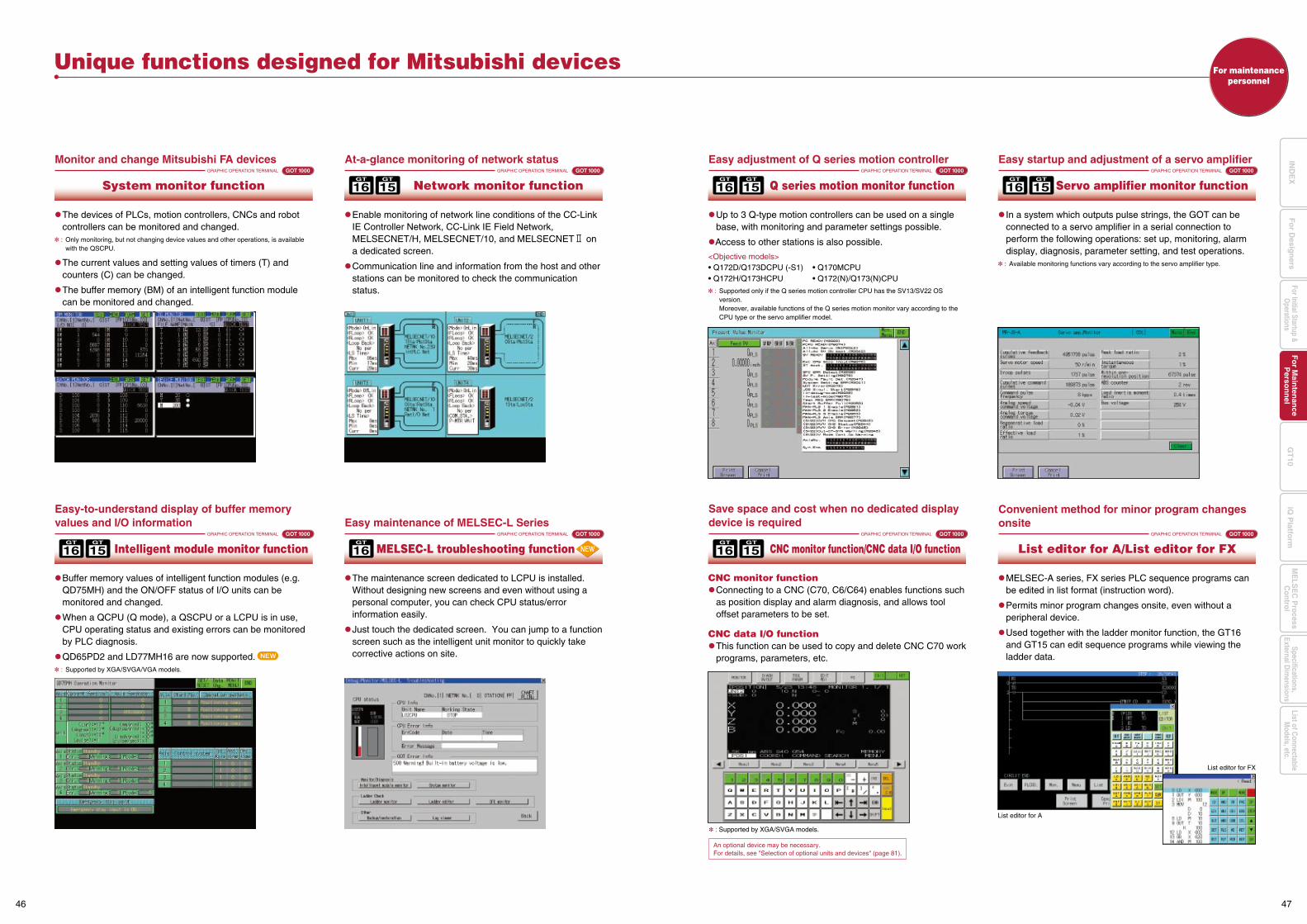
Convenient method for minor program changes onsite
For maintenancepersonnel
Unique functions designed for Mitsubishi devices
GRAPHIC OPERATION TERMINAL GOT 1000
Monitor and change Mitsubishi FA devices
The devices of PLCs, motion controllers, CNCs and robot controllers can be monitored and changed.
: Only monitoring, but not changing device values and other operations, is available with the QSCPU.
The current values and setting values of timers (T) and counters (C) can be changed.
The buffer memory (BM) of an intelligent function module can be monitored and changed.
System monitor function
GRAPHIC OPERATION TERMINAL GOT 1000
Easy-to-understand display of buffer memory values and I/O information
Buffer memory values of intelligent function modules (e.g. QD75MH) and the ON/OFF status of I/O units can be monitored and changed.
When a QCPU (Q mode), a QSCPU or a LCPU is in use, CPU operating status and existing errors can be monitored by PLC diagnosis.
QD65PD2 and LD77MH16 are now supported. : Supported by XGA/SVGA/VGA models.
Intelligent module monitor function
GRAPHIC OPERATION TERMINAL GOT 1000
At-a-glance monitoring of network status
Enable monitoring of network line conditions of the CC-Link IE Controller Network, CC-Link IE Field Network, MELSECNET/H, MELSECNET/10, and MELSECNET2 on a dedicated screen.
Communication line and information from the host and other stations can be monitored to check the communication status.
Network monitor function16GT
15GT
GRAPHIC OPERATION TERMINAL GOT 1000
Easy adjustment of Q series motion controller
Up to 3 Q-type motion controllers can be used on a single base, with monitoring and parameter settings possible.
Access to other stations is also possible.
<Objective models>• Q172D/Q173DCPU (-S1) • Q170MCPU• Q172H/Q173HCPU • Q172(N)/Q173(N)CPU
: Supported only if the Q series motion controller CPU has the SV13/SV22 OS version.
Moreover, available functions of the Q series motion monitor vary according to the CPU type or the servo amplifier model.
Q series motion monitor function16GT
15GT
GRAPHIC OPERATION TERMINAL GOT 1000
Save space and cost when no dedicated display device is required
CNC monitor function Connecting to a CNC (C70, C6/C64) enables functions such
as position display and alarm diagnosis, and allows tool offset parameters to be set.
CNC data I/O function This function can be used to copy and delete CNC C70 work
programs, parameters, etc.
CNC monitor function/CNC data I/O function16GT
15GT
GRAPHIC OPERATION TERMINAL GOT 1000
Easy startup and adjustment of a servo amplifier
In a system which outputs pulse strings, the GOT can be connected to a servo amplifier in a serial connection to perform the following operations: set up, monitoring, alarm display, diagnosis, parameter setting, and test operations.
: Available monitoring functions vary according to the servo amplifier type.
Servo amplifier monitor function16GT
15GT
16GT
GRAPHIC OPERATION TERMINAL GOT 1000
Easy maintenance of MELSEC-L Series
The maintenance screen dedicated to LCPU is installed. Without designing new screens and even without using a personal computer, you can check CPU status/error information easily.
Just touch the dedicated screen. You can jump to a function screen such as the intelligent unit monitor to quickly take corrective actions on site.
MELSEC-L troubleshooting function16GT
15GT
: Supported by XGA/SVGA models.
An optional device may be necessary.For details, see "Selection of optional units and devices" (page 81).
GRAPHIC OPERATION TERMINAL GOT 1000
MELSEC-A series, FX series PLC sequence programs can be edited in list format (instruction word).
Permits minor program changes onsite, even without a peripheral device.
Used together with the ladder monitor function, the GT16 and GT15 can edit sequence programs while viewing the ladder data.
List editor for A/List editor for FX
List editor for FX
List editor for A
46 47
Fo
r Main
tenan
ceP
erson
nel
GT
10iQ
Platfo
rmFor Initial Startup &
Operations
Fo
r Desig
ners
Specifications,External D
imensions
ME
LSE
C P
rocessC
ontrolList of C
onnectableM
odels, etc.IN
DE
X
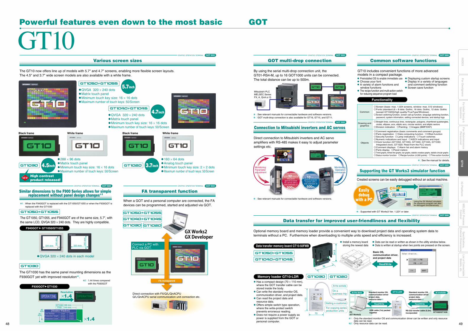
Monitoring Parameteradjustment
MonitoringOperation
commandsCan connect
up to 32 axes of Mitsubishi
general-purpose AC servos with a total extension of
500m.
Can connect
up to 10 Mitsubishi general-purpose inverters with a
total extension of
500m.
GOT 1000
Direct connection with FX/Q/L/QnACPUQ/L/QnACPU serial communication unit connection etc.
Connect a PC with PLC via GOT.
FA transparent
Mitsubishi PLCMELSEC Series FX, A, QnA or Q
Data transfer memory board GT10-50FMB
Memory loader GT10-LDR
34.8
36
GT10Powerful features even down to the most basic GOT
The GT10 now offers line up of models with 5.7" and 4.7" screens, enabling more flexible screen layouts. The 4.5" and 3.7" wide screen models are also available with a white frame.
By using the serial multi-drop connection unit, the GT01-RS4-M, up to 16 GOT1000 units can be connected. The total distance can be up to 500m.
Various screen sizes
4.7inch
5.7inch
4.5inch 3.7inch
QVGA 320 × 240 dots Matrix touch panel Minimum touch key size: 16 × 16 dots Maximum number of touch keys: 50/Screen
QVGA 320 × 240 dots Matrix touch panel Minimum touch key size: 16 × 16 dots Maximum number of touch keys: 50/Screen
288 × 96 dots Matrix touch panel Minimum touch key size: 16 × 16 dots Maximum number of touch keys: 50/Screen
160 × 64 dots Analog touch panel Minimum touch key size: 2 × 2 dots Maximum number of touch keys: 50/Screen
Black frame Black frameWhite frame White frame
1 : When the F940GOT is replaced with the GT1050/GT1055 or when the F930GOT is replaced with the GT1030
The GT1050, GT1055, and F940GOT are of the same size, 5.7", with the same LCD, QVGA 320 × 240 dots. They are highly compatible.
: See relevant manuals for connectable hardware and software versions. : GOT multi-drop connection is also available for GT16, GT15, and GT11.
The GT1030 has the same panel mounting dimensions as the F930GOT yet with improved resolution2.
When a GOT and a personal computer are connected, the FA devices can be programmed, started and adjusted via GOT.
Similar dimensions to the F900 Series allows for simple replacement without panel design changes1
GRAPHIC OPERATION TERMINAL
GOT 1000
Optional memory board and memory loader provide a convenient way to download project data and operating system data to terminals without a PC. Furthermore when downloading to multiple units speed and efficiency is increased.
Data can be read or written as shown in the utility window below. Data is written at startup when two points are pressed on the screen.
Install a memory board storing the newest data
Data transfer for improved user-friendliness and flexibilityGRAPHIC OPERATION TERMINAL
GOT 1000GRAPHIC OPERATION TERMINAL
FA transparent functionGOT 1000GRAPHIC OPERATION TERMINAL
GOT multi-drop connectionGOT 1000GRAPHIC OPERATION TERMINAL
GT10 includes convenient functions of more advanced models in a compact package.
Common software functionsGOT 1000GRAPHIC OPERATION TERMINAL
GOT 1000GRAPHIC OPERATION TERMINAL
Direct connection to Mitsubishi inverters and AC servo amplifiers with RS-485 makes it easy to adjust parameter settings etc.
: See relevant manuals for connectable hardware and software versions.
Connection to Mitsubishi inverters and AC servosGOT 1000GRAPHIC OPERATION TERMINAL
240
dots
320 dots 240
dots
320 dots
F940GOT GT1050/GT1055
QVGA 320 × 240 dots in each model
×1.4
GT1030 288 dots
96dots
80dots
F930 240 dots
F930GOT GT1030
: See the manual for details.
Comment registration (basic comments and comment groups)Parts registration Data computing function Offset functionSecurity function Lamp indications Touch switchesNumeric indications and input ASCII indications and inputClock function (GT1050, GT1055, GT1040, GT1045, GT1030: Integrated clock, GT1020: Read from the PLC clock)Comment displays Alarm list and alarm history Parts display Panel meters Trend graphs, kinked line graphs, bar graphs, statistic crossbar graphs, statistic circular graphs Status monitor function Recipe function (4,000 points) Time action function
Common
Drawing andgraphics
Screen (base: max. 1,024 screens, window: max. 512 windows)Fonts (standard (6 × 8 dots: Gothic, 16 dots: Gothic, 12 dots: Gothic [except GT1020])/high quality/TrueType/Windows)Screen switching function, screen call-up function, language switching function, password, system information, setting connected devices, and startup logo
Straight lines, continuous lines, rectangular, polygons, chamfered quadrangles, circles, ellipses, arcs, elliptic arcs, circular sectors, and elliptic sectorsDivision indication Painting Images (BMP/DXF)
Objects
Read/Write
Basic OS,communication driver,and project data
GT10-LDR
70
110
Read/Write Read/Write
For copying seriesproduction units
Standard monitor OS, communication driverproject data,resource data1
At the worksite
Visiting a customer
On a business trip At worksiteAt the desk
PC(GT Works3)
USB cable (1m) packedtogether
RS-232 transfer cable (0.2m)incorporated GT1020/GT1030
Standard monitor OS, communication driverproject data,resource data2
Resolution
×1.4
2 : 1.44 times compared with the F930GOT
Has a compact design (70 × 110 mm), where the GOT transfer cable can be stored inside the body.
Can write the standard monitor OS, communication driver, and project data.
Can read the project data and resource data.
Offers simple switch type operation, where the write-protect switch prevents erroneous reading.
Does not require a power supply as power is supplied from the GOT or personal computer.
1 : Only the standard monitor OS and communication driver can be written and only resource data can be read.
2 : Only resource data can be read.
Created screens can be easily debugged without an actual machine.
Supporting the GT Works3 simulator function
: Supported with GT Works3 Ver. 1.22Y or later.
Preinstalled OS to enable immediate use Choose your font A variety of alarm functions and
window functions The recipe function and multi-action switch
for reducing sequence program load
Displaying custom startup screens Display in a variety of languages
and comment switching function Screen save function
Easilydebug
with a PC
Click!Click!
Using the GX Works2 simulator, the sequence program can also be debugged simultaneously.
Functionality
High contrastproduct released!
48 49
Fo
r Main
tenan
ceP
erson
nel
GT
10iQ
Platfo
rmFor Initial Startup &
Operations
Fo
r Desig
ners
Specifications,External D
imensions
ME
LSE
C P
rocessC
ontrolList of C
onnectableM
odels, etc.IN
DE
X
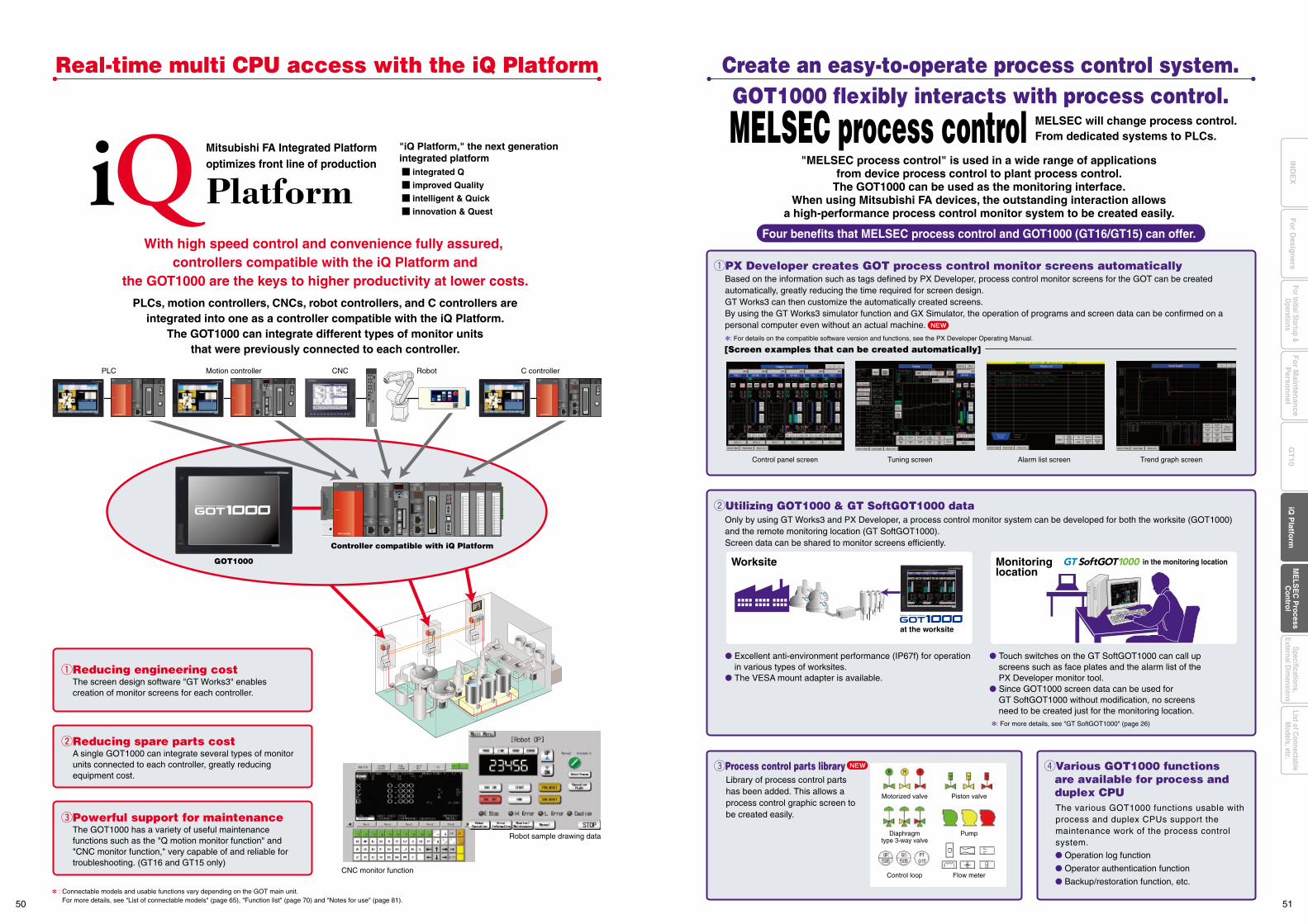
20
15
10
15
1PULL
POWERQ61P
QX41
0123456789ABCDEF
Q62AD-GH
0123456789ABCDEF
Q62AD-GH
0123456789ABCDEF
Q62AD-GHQJ71LP21
PLC Motion controller CNC
CNC monitor function
Robot sample drawing data
Robot C controller
The screen design software "GT Works3" enables creation of monitor screens for each controller.
qReducing engineering cost
A single GOT1000 can integrate several types of monitor units connected to each controller, greatly reducing equipment cost.
wReducing spare parts cost
The GOT1000 has a variety of useful maintenance functions such as the "Q motion monitor function" and "CNC monitor function," very capable of and reliable for troubleshooting. (GT16 and GT15 only)
ePowerful support for maintenance
Controller compatible with iQ Platform
GOT1000
"iQ Platform," the next generation integrated platform
integrated Q
improved Quality
intelligent & Quick
innovation & Quest
Mitsubishi FA Integrated Platformoptimizes front line of production
With high speed control and convenience fully assured, controllers compatible with the iQ Platform and
the GOT1000 are the keys to higher productivity at lower costs.
PLCs, motion controllers, CNCs, robot controllers, and C controllers areintegrated into one as a controller compatible with the iQ Platform.
The GOT1000 can integrate different types of monitor unitsthat were previously connected to each controller.
Real-time multi CPU access with the iQ Platform
: Connectable models and usable functions vary depending on the GOT main unit. For more details, see "List of connectable models" (page 65), "Function list" (page 70) and "Notes for use" (page 81).
Excellent anti-environment performance (IP67f) for operation in various types of worksites. The VESA mount adapter is available.
Touch switches on the GT SoftGOT1000 can call up screens such as face plates and the alarm list of the PX Developer monitor tool. Since GOT1000 screen data can be used for GT SoftGOT1000 without modification, no screens need to be created just for the monitoring location.
Operation log function
Operator authentication function
Backup/restoration function, etc.
at the worksite
Worksite Monitoringlocation
in the monitoring location
: For more details, see "GT SoftGOT1000" (page 26)
[Screen examples that can be created automatically]
Control panel screen Alarm list screenTuning screen Trend graph screen
qPX Developer creates GOT process control monitor screens automatically
wUtilizing GOT1000 & GT SoftGOT1000 data
eProcess control parts library
MELSEC will change process control.From dedicated systems to PLCs.
"MELSEC process control" is used in a wide range of applicationsfrom device process control to plant process control.
The GOT1000 can be used as the monitoring interface.When using Mitsubishi FA devices, the outstanding interaction allows
a high-performance process control monitor system to be created easily.
GOT1000 flexibly interacts with process control.Create an easy-to-operate process control system.
Four benefits that MELSEC process control and GOT1000 (GT16/GT15) can offer.
: For details on the compatible software version and functions, see the PX Developer Operating Manual.
rVarious GOT1000 functions are available for process and duplex CPUMotorized valve Piston valve
Diaphragmtype 3-way valve
Pump
Control loop Flow meter
MELSEC process control
Based on the information such as tags defined by PX Developer, process control monitor screens for the GOT can be created automatically, greatly reducing the time required for screen design.GT Works3 can then customize the automatically created screens.By using the GT Works3 simulator function and GX Simulator, the operation of programs and screen data can be confirmed on a personal computer even without an actual machine.
Only by using GT Works3 and PX Developer, a process control monitor system can be developed for both the worksite (GOT1000) and the remote monitoring location (GT SoftGOT1000).Screen data can be shared to monitor screens efficiently.
Library of process control parts has been added. This allows a process control graphic screen to be created easily.
The various GOT1000 functions usable with process and duplex CPUs support the maintenance work of the process control system.
50 51
Fo
r Main
tenan
ceP
erson
nel
GT
10iQ
Platfo
rmFor Initial Startup &
Operations
Fo
r Desig
ners
Specifications,External D
imensions
ME
LSE
C P
rocessC
ontrolList of C
onnectableM
odels, etc.IN
DE
X
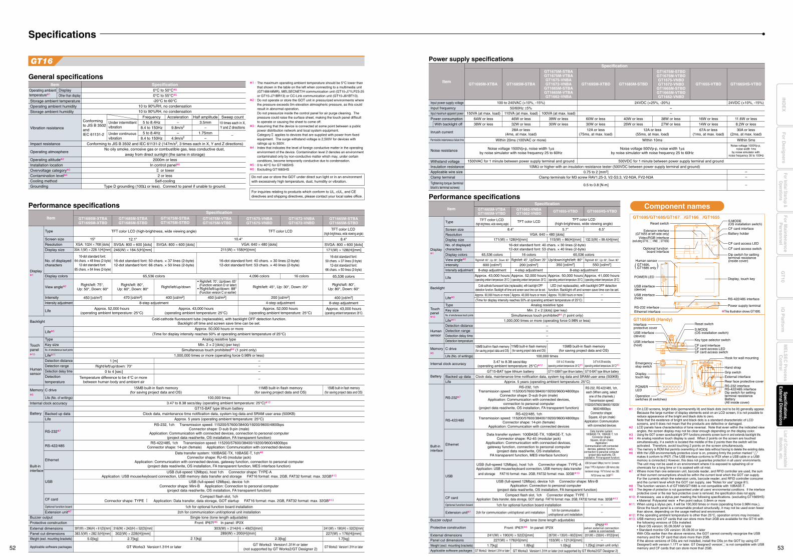
Specifications
Display1
Backlight
Touchpanel10
Humansensor
Memory5
Battery
Internal clock accuracy
Built-ininterface
Weight (excl. mounting brackets)
Applicable software packages
Buzzer output
Protective construction
External dimensionsPanel cut dimensions
Type
Screen size
Resolution
Display size
TFT color LCD (high-brightness, wide viewing angle) TFT color LCD
65,536 colors 4,096 colors 16 colors
8-step adjustment
1,000,000 times or more (operating force 0.98N or less)
1 [m]
Cold-cathode fluorescent tube (replaceable), with backlight OFF detection function.Backlight off time and screen save time can be set.
12.1"15"
XGA: 1024 × 768 [dots]304.1(W) × 228.1(H)[mm]
Right/left: 75°, Up: 50°, Down: 60°
450 [cd/m2]
Approx. 52,000 hours(operating ambient temperature: 25°C)
Approx. 43,000 hours(operating ambient temperature: 25°C)
Approx. 50,000 hours or more
Analog resistive type
SVGA: 800 × 600 [dots]246(W) × 184.5(H)[mm]
10.4"
SVGA: 800 × 600 [dots]211(W) × 158(H)[mm]
VGA: 640 × 480 [dots]
Right/left: 80°, Up: 60°, Down: 80°
Right/left/up/down
Approx. 52,000 hours(operating ambient temperature: 25°C)
Right/left: 45°, Up: 30°, Down: 20°
200 [cd/m2]
4-step adjustment
400 [cd/m2]470 [cd/m2] 450 [cd/m2]
Display colors
View angle2
Intensity
Intensity adjustment
Life
Life11
Life (No. of writings)
Detection distance
Detection range
Detection delay time
Detection
temperature
Life3
Type
Key sizeNo. of simultaneous touch points
C drive
RS-2327
RS-422/485
Ethernet
USB
CF card
Optional function board
Extension unit7
Backed up data
Life
ItemSpecification
Performance specifications
GT1695M-XTBAGT1695M-XTBD
GT1685M-STBAGT1685M-STBD
GT1675M-STBAGT1675M-STBD
GT1675M-VTBAGT1675M-VTBD
GT1675-VNBAGT1675-VNBD
GT1672-VNBAGT1672-VNBD
Min. 2 × 2 [dots] (per key)
Simultaneous touch prohibited4 (1 point only)
Right/left/up/down: 70°
0 to 4 [sec]
Temperature difference to be 4°C or more between human body and ambient air
–
–
–
–
15MB built-in flash memory(for saving project data and OS)
15MB built-in flash memory(for saving project data and OS)
11MB built-in flash memory(for saving project data and OS)
100,000 times
3.47 to 8.38 secs/day (operating ambient temperature: 25°C)12
GT15-BAT type lithium battery
Clock data, maintenance time notification data, system log data and SRAM user area (500KB)
Approx. 5 years (operating ambient temperature: 25°C)
RS-232, 1ch Transmission speed: 115200/57600/38400/19200/9600/4800bpsConnector shape: D-sub 9-pin (male)
Application: Communication with connected devices, connection to personal computer(project data read/write, OS installation, FA transparent function)
RS-422/485, 1ch Transmission speed: 115200/57600/38400/19200/9600/4800bpsConnector shape: 14-pin (female) Application: Communication with connected devices
Data transfer system: 100BASE-TX, 10BASE-T, 1ch8
Connector shape: RJ-45 (modular jack)Application: Communication with connected devices, gateway function, connection to personal computer
(project data read/write, OS installation, FA transparent function, MES interface function)
USB (full-speed 12Mbps), device 1chConnector shape: Mini-B Application: Connection to personal computer
(project data read/write, OS installation, FA transparent function)
USB (full-speed 12Mbps), host 1ch Connector shape: TYPE-AApplication: USB mouse/keyboard connection, USB memory data transfer and storage FAT16 format: max. 2GB, FAT32 format: max. 32GB13
Compact flash slot, 1chConnector shape: TYPE 1 Application: Data transfer, data storage, GOT startup FAT16 format: max. 2GB, FAT32 format: max. 32GB13
1ch for optional function board installation
2ch for communication unit/optional unit installation
Single tone (tone length adjustable)
Front: IP67f6 In panel: IP2X
397(W) × 296(H) × 61(D)[mm]
5.0[kg]383.5(W) × 282.5(H)[mm]
GT Works3 Version1.31H or later GT Works3 Version1.31H or laterGT Works3 Version1.31H or later
(not supported by GT Works2/GT Designer 2)
2.7[kg]
316(W) × 242(H) × 52(D)[mm]302(W) × 228(H)[mm]
303(W) × 214(H) × 49(D)[mm]
2.1[kg]
241(W) × 190(H) × 52(D)[mm]289(W) × 200(H)[mm]
16-dot standard font: 64 chars. × 48 lines (2-byte)
12-dot standard font: 85 chars. × 64 lines (2-byte)
16-dot standard font: 40 chars. × 30 lines (2-byte)12-dot standard font: 53 chars. × 40 lines (2-byte)
16-dot standard font: 50 chars. × 37 lines (2-byte)12-dot standard font: 66 chars. × 50 lines (2-byte)
No. of displayed characters
(Time for display intensity reaches 50% at operating ambient temperature of 25°C)
GT1665M-STBAGT1665M-STBD
2.3[kg]
• Right/left: 70°, Up/down: 65°(Function version D or later)
• Right/left/up/down: 88°(Function version C or earlier)
GT16
On LCD screens, bright dots (permanently lit) and black dots (not to be lit) generally appear. Because the large number of display elements exist on an LCD screen, it is not possible to reduce appearance of the bright and black dots to zero.Note that the existence of bright and black dots is a standard characteristic of LCD screens, and it does not mean that the products are defective or damaged.LCD panels have characteristics of tone reversal. Note that even within the indicated view angles, the screen display may not be clear enough depending on the display color.Using the GOT screen save/backlight OFF functions prevents screen burn-in and extends backlight life.An analog resistive touch display is used. When 2 points on the screen are touched simultaneously, if a switch is located the middle of the 2 points then the switch will be activated. Therefore, avoid touching 2 points on the screen simultaneously.The memory is ROM that permits overwriting of new data without having to delete the existing data.With the USB environmentally protective cover is on, pressing firmly the portion marked "[" makes it conform to IP67f. (The USB interface conforms to IP2X when a USB cable or a USB memory is connected.) However, this does not guarantee protection in all users' environments.The unit may not be used in an environment where it is exposed to splashing oil or chemicals for a long time or it is soaked with oil mist.Where more than one extension unit, barcode reader, and RFID controller are used, the sum of their current consumptions should be within the current level which the GOT can supply.For the currents which the extension units, barcode reader, and RFID controller consume and the current level which the GOT can supply, see "Notes for use" (page 81).The function version A of GT1695/GT1685 is not compatible with 10BASE-T.The degree of protection is not guaranteed under all users' environmental conditions. If the interface protective cover or the rear face protective cover is removed, the specification does not apply.If necessary, use a stylus pen meeting the following specifications. (excluding GT1665HS)• Material: Polyacetal resin • Pen point radius: 0.8mm or moreWhen using a stylus pen, it will be 100,000 times or more (operating force 0.98N max.).Since the touch panel is a consumable product structurally, it may not be used even fewer than above, depending on the usage method and environment.If the operating ambient temperature is other than 25°C, operation errors may increase.USB memory and CF cards that can store more than 2GB are available for the GT16 with the following versions of OSs installed.• Boot OS version: 05.09.00AF or later• Standard monitor OS version: 05.09.00 or laterWith OSs earlier than the above versions, the GOT cannot correctly recognize the USB memory and the CF card that store more than 2GB.If the above versions of OSs are not installed, install the OSs on the GOT by using GT Designer3 with version 1.17T or later. GT Designer2 versionM is not compatible with USB memory and CF cards that can store more than 2GB.
GT1665HS (Handy)Interface protective cover
Key type selector switch
CF card access switch
CF card interfaceCF card access LED
S.MODE(OS installation switch)
Reset switch
Hook for wall mounting
Hand strap
Rear face protective coverExternal interfaceGrip switch
USB interface(device)
USB interface(host)
POWERLED
Operation switches (6 switches)
Display, touch key
Emergency stop switch
RS-232 interfaceRS-422/485 interfaceDip switch for setting terminal resistanceBattery (All inside cover)
Do not use or store the GOT under direct sun light or in an environment with excessively high temperature, dust, humidity or vibration.
For inquiries relating to products which conform to UL, cUL, and CE directives and shipping directives, please contact your local sales office.
General specificationsItem
Operating ambienttemperature1
Vibration resistance
Impact resistance
Operating atmosphere
Operating altitude2
Installation locationOvervoltage category3
Contamination level4
Cooling methodGrounding
SpecificationDisplayOther than display
0°C to 50°C5
0°C to 55°C5
-20°C to 60°C10 to 90%RH, no condensation10 to 90%RH, no condensation
Conforming to JIS B 3502 and IEC 61131-2 (147m/s2, 3 times each in X, Y and Z directions)No oily smoke, corrosive gas or combustible gas, less conductive dust,
away from direct sunlight (the same in storage)2000m or less
In control panel6
2 or lower2 or less
Self-coolingType D grounding (100Ω or less). Connect to panel if unable to ground.
Storage ambient temperatureOperating ambient humidityStorage ambient humidity
Conforming to JIS B 3502 and IEC 61131-2
Under intermittent vibration
Under continuous vibration
Frequency5 to 8.4Hz
8.4 to 150Hz5 to 8.4Hz
8.4 to 150Hz
Half amplitude3.5mm
–1.75mm
––
Sweep count
10 times each in X,Y and Z directions
Acceleration–
9.8m/s2
–4.9m/s2
1 :
2 :
3 :
4 :
5 :6 :
The maximum operating ambient temperature should be 5°C lower than that shown in the table on the left when connecting to a multimedia unit (GT16M-MMR), MELSECNET/H communication unit (GT15-J71LP23-25 or GT15-J71BR13) or CC-Link communication unit (GT15-J61BT13).Do not operate or store the GOT unit in pressurized environments where the pressure exceeds 0m elevation atmospheric pressure, as this could result in abnormal operation.Do not pressurize inside the control panel for air purge cleaning. The pressure could raise the surface sheet, making the touch panel difficult to operate or causing the sheet to come off.Assuming that the device is connected at some point between a public power distribution network and local system equipment.Category2 applies to devices that are supplied with power from fixed equipment. The surge withstand voltage is 2,500V for devices with ratings up to 300V.Index that indicates the level of foreign conductive matter in the operating environment of the device. Contamination level 2 denotes an environment contaminated only by non-conductive matter which may, under certain conditions, become temporarily conductive due to condensation.0 to 40°C for GT1665HSExcluding GT1665HS
GT1695M-XTBA GT1695M-XTBDGT1685M-STBA
GT1675M-STBAGT1675M-VTBAGT1675-VNBAGT1672-VNBA
GT1665M-STBAGT1665M-VTBAGT1662-VNBA
GT1675M-STBDGT1675M-VTBDGT1675-VNBDGT1672-VNBD
GT1665M-STBDGT1665M-VTBDGT1662-VNBD
GT1685M-STBD
Power supply specificationsSpecification
Item
Input power supply voltage
Input frequencyInput maximum apparent power
Power consumption
With backlight off
Inrush current
Permissible instantaneous failure time
Noise resistance
Withstand voltageInsulation resistanceApplicable wire size
Clamp terminal
Tightening torque (terminalblock's terminal screws)
150VA (at max. load) 110VA (at max. load) 100VA (at max. load) –
64W or less
38W or less
60W or less
30W or less
12A or less(75ms, at max. load)
46W or less
32W or less
39W or less
30W or less
40W or less
26W or less
38W or less
27W or less
12A or less(55ms, at max. load)
67A or less(1ms, at max. load)
10MΩ or higher with an insulation resistance tester (500VDC between power supply terminal and ground)
0.75 to 2 [mm2]Clamp terminals for M3 screw RAV1.25-3, V2-S3.3, V2-N3A, FV2-N3A
0.5 to 0.8 [N·m]
24VDC (+25%, -20%)
–
–
–
–
Within 10ms
Noise voltage 500Vp-p, noise width 1µsby noise simulator with noise frequency 25 to 60Hz
GT1655-VTBD GT1665HS-VTBD
16W or less
14W or less
24VDC (+10%, -15%)
30A or less(2ms, at max. load)
11.6W or less
8.2W or less
Within 5msNoise voltage 1000Vp-p,
noise width 1msby noise simulator with
noise frequency 30 to 100Hz
500VDC for 1 minute between power supply terminal and ground
100 to 240VAC (+10%, -15%)
50/60Hz ±5%
28A or less(4ms, at max. load)
Within 20ms (100VAC or more)
Noise voltage 1500Vp-p, noise width 1µsby noise simulator with noise frequency 25 to 60Hz
1500VAC for 1 minute between power supply terminal and ground
Display1
Backlight
Touchpanel10
Humansensor
Memory5
Battery
Weight (excl. mounting brackets)Applicable software packages
Buzzer output
Protective construction
External dimensionsPanel cut dimensions
Type
Screen size
Resolution
Display size
TFT color LCD (high-brightness, wide viewing angle)
TFT color LCD (high-brightness, wide viewing angle)
TFT color LCD
65,536 colors
65,536 colors
8-step adjustment
8-step adjustment
1,000,000 times or more (operating force 0.98N or less)
Cold-cathode fluorescent tube (replaceable), with backlight OFFdetection function. Backlight off time and screen save time can be set.
LED (not replaceable), with backlight OFF detectionfunction. Backlight off and screen save time can be set.
8.4" 5.7"
8.4"
6.5"
SVGA: 800 × 600 [dots]171(W) × 128(H)[mm]
171(W) × 128(H)[mm]
132.5(W) × 99.4(H)[mm]115(W) × 86(H)[mm]
Right/left: 80°, Up: 80°, Down: 60°
Right/left: 80°,Up: 80°, Down: 60°
400 [cd/m2]
Approx. 43,000 hours(operating ambient temperature: 25°C)
Approx. 43,000 hours(operating ambient temperature: 25°C)
16 colors
4-step adjustment
Up/down/right/left: 80°Right/left: 45°, Up/Down: 20°350 [cd/m2]
Approx. 52,000 hours(operating ambient temperature: 25°C)
65,536 colors
8-step adjustment
Right/left: 80°, Up: 60°, Down: 80°
550 [cd/m2]
Approx. 41,000 hours(operating ambient temperature: 25°C)
Approx. 50,000 hours(operating ambient temperature: 25°C)
(Time for display intensity reaches 50% at operating ambient temperature of 25°C)
Approx. 50,000 hours or more Approx. 70,000 hours or moreApprox. 40,000 hours or more
Analog resistive type
VGA: 640 × 480 [dots]
200 [cd/m2]600 [cd/m2]
Display colors
View angle2
Intensity
Intensity adjustment
Life
Life11
Life (No. of writings)
Detection distance
Detection range
Detection delay time
Detection temperature
Life3
Type
Key sizeNo. of simultaneous touch points
C drive
RS-2327
RS-422/485
Ethernet
USB
CF card
Optional function board
Extension unit7
Backed up data
Life
ItemSpecification
Performance specifications
GT1665M-VTBAGT1665M-VTBD
11MB built-in flash memory(for saving project data and OS)
15MB built-in flash memory(for saving project data and OS)
GT1662-VNBAGT1662-VNBD GT1665HS-VTBDGT1655-VTBD
Min. 2 × 2 [dots] (per key)
Simultaneous touch prohibited4 (1 point only)
15MB built-in flash memory(for saving project data and OS)
100,000 times
GT15-BAT type lithium battery GT15-BAT type lithium batteryGT11-50BAT type lithium battery
Clock data, maintenance time notification data, system log data and SRAM user area (500KB)
Internal clock accuracy 3.47 to 8.38 secs/day(operating ambient temperature: 25°C)12
-3.61 to 2.16 secs/day(operating ambient temperature: 25°C)12
3.47 to 8.38 secs/day(operating ambient temperature: 25°C)12
Approx. 5 years (operating ambient temperature: 25°C)
RS-232, 1chTransmission speed: 115200/57600/38400/19200/9600/4800bps
Connector shape: D-sub 9-pin (male)Application: Communication with connected devices,
connection to personal computer(project data read/write, OS installation, FA transparent function)
RS-422/485, 1chTransmission speed: 115200/57600/38400/19200/9600/4800bps
Connector shape: 14-pin (female)Application: Communication with connected devices
Data transfer system: 100BASE-TX, 10BASE-T, 1chConnector shape: RJ-45 (modular jack)
Application: Communication with connected devices, gateway function, connection to personal computer
(project data read/write, OS installation,FA transparent function, MES interface function)
RS-232, RS-422/485, 1ch, each (When using, select
one of the channels.)Transmission speed:
115200/57600/38400/19200/9600/4800bps
Connector shape: Square, 42-pin (male)
Application: Communication with connected devices
Data transfer system: 100BASE-TX, 10BASE-T, 1ch
Connector shape: Square, 42-pin (male)
Application: Communication with connected
devices, gateway function, connection to personal computer
(project data read/write, OSinstallation, FA transparent function)
USB (full-speed 12Mbps), device 1ch Connector shape: Mini-BApplication: Connection to personal computer
(project data read/write, OS installation, FA transparent function)
USB (full-speed 12Mbps), host 1ch Connector shape: TYPE-AApplication: USB mouse/keyboard connection, USB memory data transfer
and storage FAT16 format: max. 2GB, FAT32 format: max. 32GB13
USB (full-speed 12Mbps), host 1ch Connector
shape: TYPE-A Application: USB memory datatransferand storage FAT16 format: max. 2GB,
FAT32 format: max. 32GB13
Compact flash slot, 1ch Connector shape: TYPE 1Application: Data transfer, data storage, GOT startup FAT16 format: max. 2GB, FAT32 format: max. 32GB13
1ch for optional function board installation
2ch for communication unit/optional unit installation1ch for communication
unit/optional unit installation
Single tone (tone length adjustable)
Front: IP67f6 In panel: IP2X
241(W) × 190(H) × 52(D)[mm]
1.8[kg]1.7[kg] 1.0[kg] 1.2[kg] (main unit only)227(W) × 176(H)[mm]
267(W) × 135(H) × 60(D)[mm]153(W) × 121(H)[mm]
GT Works3 Version1.31H or later
16-dot standard font:50 chars. × 37 lines (2-byte)
12-dot standard font:66 chars. × 50 lines (2-byte)
16-dot standard font: 40 chars. × 30 lines (2-byte)12-dot standard font: 53 chars. × 40 lines (2-byte)
No. of displayed characters
–
–
–
–
–
–
–
IP65f9
(when external connection cable is connected)
201(W) × 230(H) × 97(D)[mm]
–
–
1.7[kg]227(W) × 176(H)[mm]
GT Works3 Version1.31H or later (not supported by GT Works2/GT Designer 2)
Built-ininterface
Component namesGT1695/GT1685/GT167M/GT166M/GT1655
POWER LED
USB interface(device)
USB interface(host)
RS-232 interfaceEthernet interface
RS-422/485 interface
Power supply terminal
This illustration shows GT1695.
Display, touch key
Extension interface(GT1655 at left side only)
CF card interface
Reset switch
Battery holder
CF card access LED
CF card access switch
Dip switch for setting terminal resistance (inside cover)
Video/RGB interface(excluding GT16MM-VNBM, GT1655)
Optional function board interface
S.MODE (OS installation switch)
1 :
2 :
3 :4 :
5 :6 :
7 :
8 :9 :
10 :
11:
12 :13 :
( )Human sensorGT1695, GT1685 only
TFT color LCD(high-brightness, wide viewing angle)
52 53
Fo
r Main
tenan
ceP
erson
nel
GT
10iQ
Platfo
rmFor Initial Startup &
Operations
Fo
r Desig
ners
Specifications,External D
imensions
ME
LSE
C P
rocessC
ontrolList of C
onnectableM
odels, etc.IN
DE
X
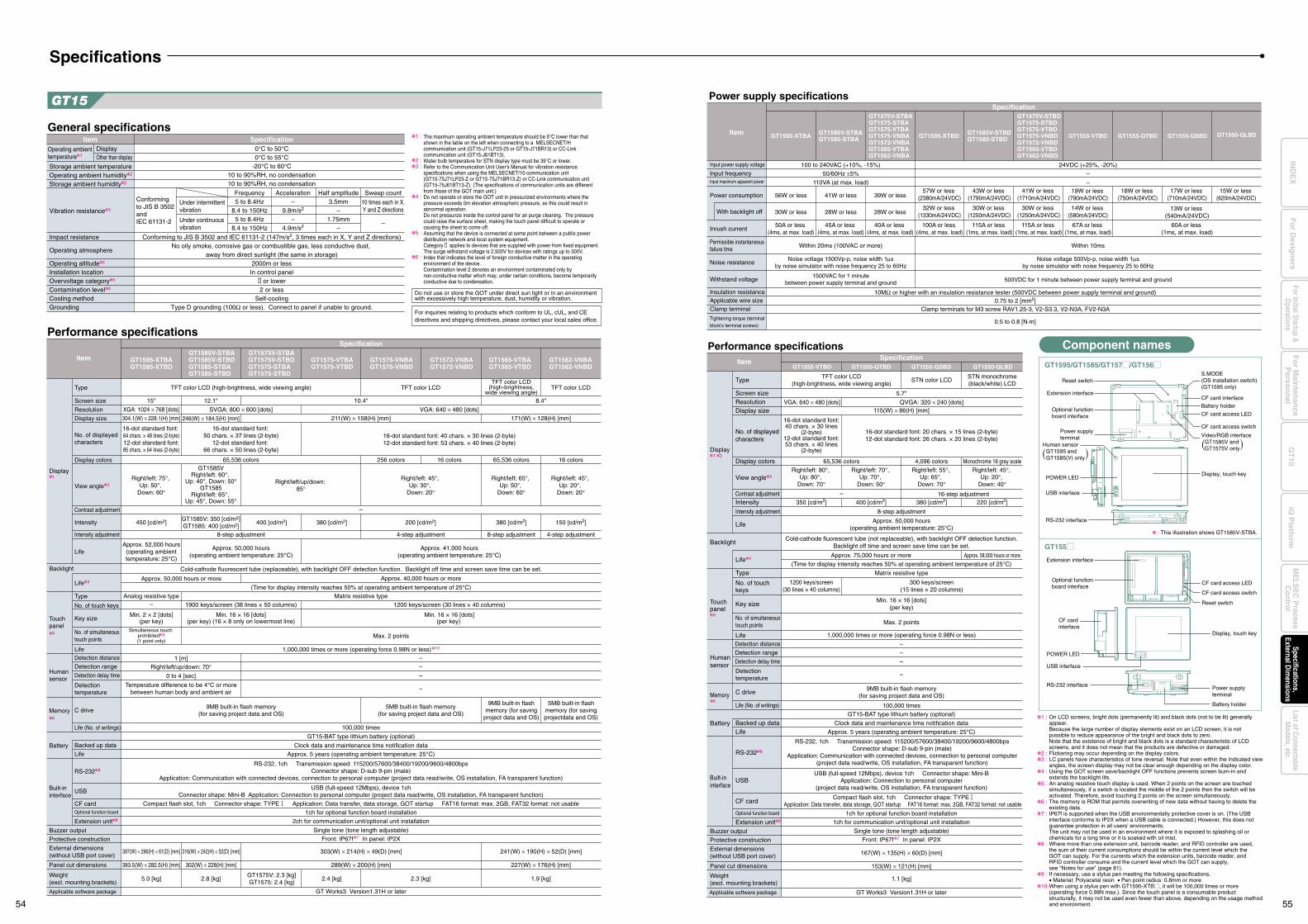
GT15
–
Display1
Backlight
Touch panel9
Human sensor
Memory6
Battery
Built-in interface
Weight(excl. mounting brackets)
Applicable software package
Buzzer output
Protective construction
External dimensions(without USB port cover)
Panel cut dimensions
Type
Screen size
Resolution
Display size
No. of displayed characters
Display colors 65,536 colorsGT1585V
Right/left: 60°, Up: 40°, Down: 50°
GT1585Right/left: 65°,
Up: 45°, Down: 55°
Right/left/up/down: 85°
Right/left: 45°, Up: 30°,
Down: 20°
Right/left: 75°, Up: 50°,
Down: 60°
450 [cd/m2]GT1585V: 350 [cd/m2]GT1585: 400 [cd/m2]
200 [cd/m2]400 [cd/m2] 380 [cd/m2]
256 colors 16 colors
View angle3
Contrast adjustment
Intensity
Intensity adjustment
LifeApprox. 52,000 hours
(operating ambienttemperature: 25°C)
Approx. 50,000 hours(operating ambient temperature: 25°C)
8-step adjustment
Approx. 40,000 hours or more
(Time for display intensity reaches 50% at operating ambient temperature of 25°C)Matrix resistive type
Max. 2 points
1 [m]Right/left/up/down: 70°
0 to 4 [sec]
Temperature difference to be 4°C or morebetween human body and ambient air
–
–
–
–
1,000,000 times or more (operating force 0.98N or less)10
100,000 times
GT15-BAT type lithium battery (optional)
Clock data and maintenance time notification data
1ch for optional function board installation
2ch for communication unit/optional unit installation
Single tone (tone length adjustable)
303(W) × 214(H) × 49(D) [mm]
289(W) × 200(H) [mm]
2.3 [kg]2.4 [kg]
GT Works3 Version1.31H or later
5.0 [kg] 2.8 [kg]GT1575V: 2.3 [kg]GT1575: 2.4 [kg]
397(W) × 296(H) × 61(D) [mm] 316(W) × 242(H) × 52(D) [mm]
383.5(W) × 282.5(H) [mm] 302(W) × 228(H) [mm]
Front: IP67f7 In panel: IP2X
Approx. 5 years (operating ambient temperature: 25°C)
USB (full-speed 12Mbps), device 1chConnector shape: Mini-B Application: Connection to personal computer (project data read/write, OS installation, FA transparent function)
RS-232, 1ch Transmission speed: 115200/57600/38400/19200/9600/4800bpsConnector shape: D-sub 9-pin (male)
Application: Communication with connected devices, connection to personal computer (project data read/write, OS installation, FA transparent function)
9MB built-in flash memory(for saving project data and OS)
5MB built-in flash memory(for saving project data and OS)
1200 keys/screen (30 lines × 40 columns)1900 keys/screen (38 lines × 50 columns)
Approx. 50,000 hours or more
Analog resistive type
Min. 2 × 2 [dots](per key)
Min. 16 × 16 [dots](per key) (16 × 8 only on lowermost line)
Min. 16 × 16 [dots](per key)
Simultaneous touch prohibited5
(1 point only)
–
Cold-cathode fluorescent tube (replaceable), with backlight OFF detection function. Backlight off time and screen save time can be set.
4-step adjustment
Approx. 41,000 hours(operating ambient temperature: 25°C)
Life
Life (No. of writings)
Detection distance
Detection range
Detection delay time
Detectiontemperature
Life4
Type
No. of touch keys
Key size
No. of simultaneous touch points
C drive
RS-2328
USB
CF cardOptional function board
Extension unit8
Backed up data
Life
TFT color LCD (high-brightness, wide viewing angle) TFT color LCD
SVGA: 800 × 600 [dots]
12.1" 10.4"
VGA: 640 × 480 [dots]
246(W) × 184.5(H) [mm] 211(W) × 158(H) [mm]
15"
XGA: 1024 × 768 [dots]
304.1(W) × 228.1(H) [mm]
16-dot standard font: 64 chars. × 48 lines (2-byte)12-dot standard font:85 chars. × 64 lines (2-byte)
16-dot standard font: 50 chars. × 37 lines (2-byte)
12-dot standard font: 66 chars. × 50 lines (2-byte)
16-dot standard font: 40 chars. × 30 lines (2-byte)12-dot standard font: 53 chars. × 40 lines (2-byte)
Item
SpecificationPerformance specifications
GT1595-XTBAGT1595-XTBD
GT1585V-STBAGT1585V-STBDGT1585-STBAGT1585-STBD
GT1575V-STBAGT1575V-STBDGT1575-STBAGT1575-STBD
GT1575-VTBAGT1575-VTBD
GT1575-VNBAGT1575-VNBD
GT1572-VNBAGT1572-VNBD
65,536 colors 16 colors
Right/left: 65°, Up: 50°,
Down: 60°
Right/left: 45°, Up: 20°,
Down: 20°
380 [cd/m2] 150 [cd/m2]
8-step adjustment 4-step adjustment
1.9 [kg]
241(W) × 190(H) × 52(D) [mm]
227(W) × 176(H) [mm]
9MB built-in flashmemory (for saving
project data and OS)
5MB built-in flashmemory (for savingprojectdata and OS)
TFT color LCDTFT color LCD
(high-brightness,wide viewing angle)
8.4"
171(W) × 128(H) [mm]
GT1565-VTBAGT1565-VTBD
GT1562-VNBAGT1562-VNBD
( )
Component names
GT1595/GT1585/GT157M/GT156M
GT155M
POWER LED
Power supplyterminal
Extension interface
Optional functionboard interface
Optional functionboard interface
CF card interface
CF card interface
S.MODE(OS installation switch)(GT1595 only)
CF card access LED
Reset switch
Reset switch
Battery holder
Battery holder
USB interface
CF card access switch
Video/RGB interfaceGT1585V andGT1575V only
CF card access switch
RS-232 interface
Power supply terminal
Display, touch key
RS-232 interface
Human sensorGT1595 andGT1585(V) only
POWER LED
USB interface
Display, touch key
CF card access LED
( )
Noise voltage 500Vp-p, noise width 1µsby noise simulator with noise frequency 25 to 60Hz
Power supply specificationsSpecification
Item
Input power supply voltage
Input frequencyInput maximum apparent power
Power consumption
With backlight off
Inrush current
Permissible instantaneousfailure time
Noise resistance
Insulation resistanceApplicable wire sizeClamp terminal
Withstand voltage
Tightening torque (terminalblock's terminal screws)
GT1595-XTBA GT1595-XTBDGT1585V-STBAGT1585-STBA
GT1575V-STBAGT1575-STBAGT1575-VTBAGT1575-VNBAGT1572-VNBAGT1565-VTBAGT1562-VNBA
GT1585V-STBDGT1585-STBD
GT1575V-STBDGT1575-STBDGT1575-VTBDGT1575-VNBDGT1572-VNBDGT1565-VTBDGT1562-VNBD
100 to 240VAC (+10%, -15%)
Noise voltage 1500Vp-p, noise width 1µsby noise simulator with noise frequency 25 to 60Hz
Within 20ms (100VAC or more)
1500VAC for 1 minutebetween power supply terminal and ground 500VDC for 1 minute between power supply terminal and ground
10MΩ or higher with an insulation resistance tester (500VDC between power supply terminal and ground)0.75 to 2 [mm2]
Clamp terminals for M3 screw RAV1.25-3, V2-S3.3, V2-N3A, FV2-N3A
0.5 to 0.8 [N·m]
50/60Hz ±5%
110VA (at max. load)
56W or less
30W or less
50A or less (4ms, at max. load)
41W or less
28W or less
45A or less (4ms, at max. load)
39W or less
28W or less
40A or less (4ms, at max. load)
57W or less (2380mA/24VDC)
100A or less (4ms, at max. load)
43W or less (1790mA/24VDC)
115A or less (1ms, at max. load)
41W or less (1710mA/24VDC)
115A or less (1ms, at max. load)
24VDC (+25%, -20%)
–
Within 10ms
–15W or less
(620mA/24VDC)17W or less
(710mA/24VDC)18W or less
(750mA/24VDC)
13W or less (540mA/24VDC)
60A or less (1ms, at max. load)
19W or less (790mA/24VDC)
32W or less (1330mA/24VDC)
30W or less (1250mA/24VDC)
30W or less (1250mA/24VDC)
14W or less (580mA/24VDC)
67A or less (1ms, at max. load)
GT1555-VTBD GT1555-QTBD GT1555-QSBD GT1550-QLBD
VGA: 640 × 480 [dots]
350 [cd/m2]
GT1555-VTBD GT1555-QTBD GT1555-QSBD GT1550-QLBD
Display1 2
Backlight
Touch panel9
Human sensor
Memory6
Battery
Built-in interface
Weight(excl. mounting brackets)
Buzzer output
Protective construction
External dimensions(without USB port cover)
Panel cut dimensions
Type
Screen sizeResolutionDisplay size
No. of displayed characters
Display colors
View angle3
Contrast adjustmentIntensity
Intensity adjustment
Life
Life
Life (No. of writings)
Detection distance
Detection range
Detection delay time
Life4
Type
No. of touch keys
Key size
No. of simultaneous touch points
C drive
RS-2328
USB
CF card
Optional function board
Extension unit8
Backed up dataLife
Item
65,536 colorsRight/left: 80°,
Up: 80°, Down: 70°
Right/left: 70°, Up: 70°,
Down: 50°
Right/left: 55°, Up: 65°,
Down: 70°
Right/left: 45°, Up: 20°,
Down: 40°
380 [cd/m2] 220 [cd/m2]400 [cd/m2]
4,096 colors Monochrome 16 gray scale
Approx. 50,000 hours(operating ambient temperature: 25°C)
8-step adjustment
Approx. 75,000 hours or more Approx. 58,000 hours or more
(Time for display intensity reaches 50% at operating ambient temperature of 25°C)
Matrix resistive type
Max. 2 points
–
–
–
–
1,000,000 times or more (operating force 0.98N or less)
100,000 timesGT15-BAT type lithium battery (optional)
Clock data and maintenance time notification data
Compact flash slot, 1ch Connector shape: TYPE Application: Data transfer, data storage, GOT startup FAT16 format: max. 2GB, FAT32 format: not usable
1ch for optional function board installation1ch for communication unit/optional unit installation
Single tone (tone length adjustable)
167(W) × 135(H) × 60(D) [mm]
153(W) × 121(H) [mm]
1.1 [kg]
GT Works3 Version1.31H or later
Front: IP67f7 In panel: IP2X
Approx. 5 years (operating ambient temperature: 25°C)
USB (full-speed 12Mbps), device 1ch Connector shape: Mini-BApplication: Connection to personal computer
(project data read/write, OS installation, FA transparent function)
RS-232, 1ch Transmission speed: 115200/57600/38400/19200/9600/4800bpsConnector shape: D-sub 9-pin (male)
Application: Communication with connected devices, connection to personal computer(project data read/write, OS installation, FA transparent function)
9MB built-in flash memory(for saving project data and OS)
300 keys/screen(15 lines × 20 columns)
1200 keys/screen(30 lines × 40 columns)
Min. 16 × 16 [dots](per key)
Cold-cathode fluorescent tube (not replaceable), with backlight OFF detection function.Backlight off time and screen save time can be set.
16-step adjustment–
TFT color LCD(high-brightness, wide viewing angle)
STN color LCDSTN monochrome(black/white) LCD
5.7"
QVGA: 320 × 240 [dots]115(W) × 86(H) [mm]
16-dot standard font: 20 chars. × 15 lines (2-byte)12-dot standard font: 26 chars. × 20 lines (2-byte)
16-dot standard font:40 chars. × 30 lines
(2-byte)12-dot standard font:53 chars. × 40 lines
(2-byte)
Performance specificationsSpecification
: This illustration shows GT1585V-STBA.
Detectiontemperature
On LCD screens, bright dots (permanently lit) and black dots (not to be lit) generally appear. Because the large number of display elements exist on an LCD screen, it is not possible to reduce appearance of the bright and black dots to zero.Note that the existence of bright and black dots is a standard characteristic of LCD screens, and it does not mean that the products are defective or damaged.Flickering may occur depending on the display colors.LC panels have characteristics of tone reversal. Note that even within the indicated view angles, the screen display may not be clear enough depending on the display color. Using the GOT screen save/backlight OFF functions prevents screen burn-in and extends the backlight life.An analog resistive touch display is used. When 2 points on the screen are touched simultaneously, if a switch is located the middle of the 2 points then the switch will be activated. Therefore, avoid touching 2 points on the screen simultaneously.The memory is ROM that permits overwriting of new data without having to delete the existing data.IP67f is supported when the USB environmentally protective cover is on. (The USBinterface conforms to IP2X when a USB cable is connected.) However, this does notguarantee protection in all users' environments.The unit may not be used in an environment where it is exposed to splashing oil orchemicals for a long time or it is soaked with oil mist.Where more than one extension unit, barcode reader, and RFID controller are used,the sum of their current consumptions should be within the current level which theGOT can supply. For the currents which the extension units, barcode reader, andRFID controller consume and the current level which the GOT can supply,see "Notes for use" (page 81).If necessary, use a stylus pen meeting the following specifications.• Material: Polyacetal resin • Pen point radius: 0.8mm or moreWhen using a stylus pen with GT1595-XTBM, it will be 100,000 times or more(operating force 0.98N max.). Since the touch panel is a consumable productstructurally, it may not be used even fewer than above, depending on the usage methodand environment.
Applicable software package
1 :
2 :3 :
4 :
5 :
6 :
7 :
8 :
9 :
10:
Extension interface
Compact flash slot, 1ch Connector shape: TYPE Application: Data transfer, data storage, GOT startup FAT16 format: max. 2GB, FAT32 format: not usable
General specifications
Do not use or store the GOT under direct sun light or in an environment with excessively high temperature, dust, humidity or vibration.
ItemOperating ambient temperature1
Vibration resistance3
Impact resistance
Operating atmosphere
Operating altitude4
Installation locationOvervoltage category5
Contamination level6
Cooling methodGrounding
SpecificationDisplayOther than display
0°C to 50°C0°C to 55°C
-20°C to 60°C10 to 90%RH, no condensation10 to 90%RH, no condensation
Conforming to JIS B 3502 and IEC 61131-2 (147m/s2, 3 times each in X, Y and Z directions)No oily smoke, corrosive gas or combustible gas, less conductive dust,
away from direct sunlight (the same in storage)2000m or less
In control panel or lower2 or less
Self-coolingType D grounding (100Ω or less). Connect to panel if unable to ground.
Storage ambient temperatureOperating ambient humidity2
Storage ambient humidity2
Conforming to JIS B 3502 and IEC 61131-2
Under intermittentvibration
Under continuous vibration
Frequency5 to 8.4Hz
8.4 to 150Hz5 to 8.4Hz
8.4 to 150Hz
Half amplitude3.5mm
–1.75mm
–
Sweep count
10 times each in X,Y and Z directions
–
Acceleration–
9.8m/s2
–4.9m/s2
The maximum operating ambient temperature should be 5°C lower than that shown in the table on the left when connecting to a MELSECNET/H communication unit (GT15-J71LP23-25 or GT15-J71BR13) or CC-Link communication unit (GT15-J61BT13).Water bulb temperature for STN display type must be 39°C or lower. Refer to the Communication Unit User's Manual for vibration resistance specifications when using the MELSECNET/10 communication unit (GT15-75J71LP23-Z or GT15-75J71BR13-Z) or CC-Link communication unit (GT15-75J61BT13-Z). (The specifications of communication units are different from those of the GOT main unit.)Do not operate or store the GOT unit in pressurized environments where the pressure exceeds 0m elevation atmospheric pressure, as this could result in abnormal operation.Do not pressurize inside the control panel for air purge cleaning. The pressure could raise the surface sheet, making the touch panel difficult to operate or causing the sheet to come off.Assuming that the device is connected at some point between a public power distribution network and local system equipment. Category2 applies to devices that are supplied with power from fixed equipment. The surge withstand voltage is 2,500V for devices with ratings up to 300V.Index that indicates the level of foreign conductive matter in the operating environment of the device. Contamination level 2 denotes an environment contaminated only by non-conductive matter which may, under certain conditions, become temporarily conductive due to condensation.
1 :
2 :3 :
4 :
5 :
6 :
Specifications
For inquiries relating to products which conform to UL, cUL, and CE directives and shipping directives, please contact your local sales office.
54 55
Fo
r Main
tenan
ceP
erson
nel
GT
10iQ
Platfo
rmFor Initial Startup &
Operations
Fo
r Desig
ners
Specifications,External D
imensions
ME
LSE
C P
rocessC
ontrolList of C
onnectableM
odels, etc.IN
DE
X
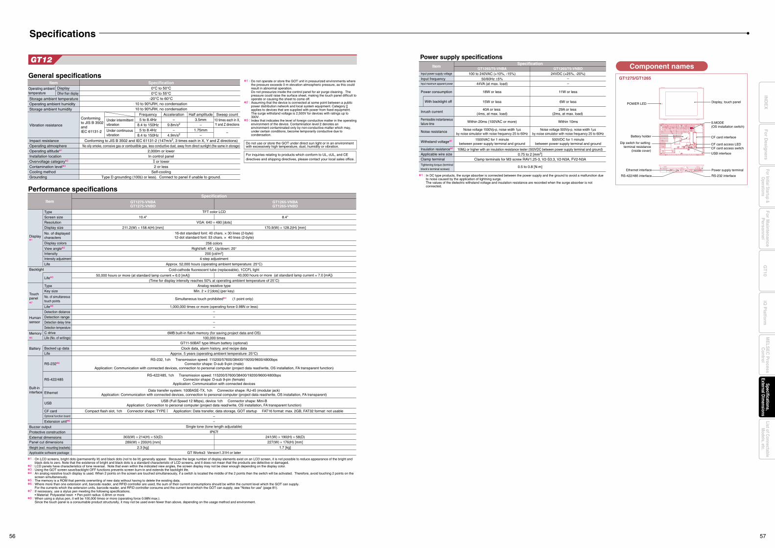
GT12
Display1
Backlight
Touch panel7
Human sensor
Memory5
Battery
Built-in interface
Weight (excl. mounting brackets)Applicable software package
Buzzer output
Protective construction
External dimensionsPanel cut dimensions
Type
Screen size
Resolution
Display size
No. of displayed characters
Display colors 256 colors
Right/left: 45°, Up/down: 20°200 [cd/m2]
View angle2
IntensityIntensity adjustment
Life Approx. 52,000 hours (operating ambient temperature: 25°C)
4-step adjustment
40,000 hours or more (at standard lamp current = 7.0 [mA])
(Time for display intensity reaches 50% at operating ambient temperature of 25˚C)Analog resistive type
–
–
–
–
1,000,000 times or more (operating force 0.98N or less)
100,000 timesGT11-50BAT type lithium battery (optional)
Clock data, alarm history, and recipe data
–
–Single tone (tone length adjustable)
GT Works3 Version1.31H or later2.3 [kg]
303(W) × 214(H) × 53(D)
289(W) × 200(H) [mm]
IP67f
Approx. 5 years (operating ambient temperature: 25°C)
RS-232, 1ch Transmission speed: 115200/57600/38400/19200/9600/4800bpsConnector shape: D-sub 9-pin (male)
Application: Communication with connected devices, connection to personal computer (project data read/write, OS installation, FA transparent function)
RS-422/485, 1ch Transmission speed: 115200/57600/38400/19200/9600/4800bpsConnector shape: D-sub 9-pin (female)
Application: Communication with connected devices
USB (Full Speed 12 Mbps), device 1ch Connector shape: Mini-BApplication: Connection to personal computer (project data read/write, OS installation, FA transparent function)
Data transfer system: 100BASE-TX, 1ch Connector shape: RJ-45 (modular jack)Application: Communication with connected devices, connection to personal computer (project data read/write, OS installation, FA transparent)
6MB built-in flash memory (for saving project data and OS)
50,000 hours or more (at standard lamp current = 6.0 [mA])
Min. 2 × 2 [dots] (per key)
Simultaneous touch prohibited4 (1 point only)
Cold-cathode fluorescent tube (replaceable), 1CCFL light
Life8
Life (No. of writings)
Detection distance
Detection range
Detection delay time
Detection temperature
Life3
Type
Key size
No. of simultaneous touch points
C drive
RS-2326
RS-422/485
Ethernet
USB
CF cardOptional function board
Extension unit6
Backed up data
Life
TFT color LCD
VGA: 640 × 480 [dots]
211.2(W) × 158.4(H) [mm] 170.9(W) × 128.2(H) [mm]
10.4" 8.4"
16-dot standard font: 40 chars. × 30 lines (2-byte)12-dot standard font: 53 chars. × 40 lines (2-byte)
ItemSpecification
Performance specifications
GT1275-VNBAGT1275-VNBD
GT1265-VNBAGT1265-VNBD
Component names
GT1275/GT1265
Power supply specificationsSpecification
Item
Input power supply voltage
Input frequencyInput maximum apparent power
Power consumption
With backlight off
Inrush current
Permissible instantaneousfailure time
Noise resistance
Insulation resistance1
Applicable wire sizeClamp terminal
Withstand voltage1
Tightening torque (terminalblock's terminal screws)
GT1265/75-VNBA GT1265/75-VNBD100 to 240VAC (+10%, -15%) 24VDC (+25%, -20%)
Noise voltage 1500Vp-p, noise width 1µsby noise simulator with noise frequency 25 to 60Hz
Noise voltage 500Vp-p, noise width 1µsby noise simulator with noise frequency 25 to 60Hz
Within 20ms (100VAC or more) Within 10ms
1500VAC for 1 minutebetween power supply terminal and ground
500VDC for 1 minutebetween power supply terminal and ground
10MΩ or higher with an insulation resistance tester (500VDC between power supply terminal and ground)0.75 to 2 [mm2]
Clamp terminals for M3 screw RAV1.25-3, V2-S3.3, V2-N3A, FV2-N3A
0.5 to 0.8 [N·m]
50/60Hz ±5%44VA (at max. load)
18W or less
15W or less
40A or less (4ms, at max. load)
11W or less
6W or less
29A or less (2ms, at max. load)
––
Compact flash slot, 1ch Connector shape: TYPE Application: Data transfer, data storage, GOT startup FAT16 format: max. 2GB, FAT32 format: not usable
1.7 [kg]
241(W) × 190(H) × 58(D)
227(W) × 176(H) [mm]
In DC type products, the surge absorber is connected between the power supply and the ground to avoid a malfunction due to noise caused by the application of lightning surge.The values of the dielectric withstand voltage and insulation resistance are recorded when the surge absorber is not connected.
1 :
General specifications
Do not use or store the GOT under direct sun light or in an environment with excessively high temperature, dust, humidity or vibration.
ItemOperating ambient temperature
Vibration resistance
Impact resistanceOperating atmosphereOperating altitude1
Installation locationOvervoltage category2
Contamination level3
Cooling methodGrounding
SpecificationDisplayOther than display
0°C to 50°C0°C to 55°C
-20°C to 60°C10 to 90%RH, no condensation10 to 90%RH, no condensation
Conforming to JIS B 3502 and IEC 61131-2 (147m/s2, 3 times each in X, Y and Z directions)No oily smoke, corrosive gas or combustible gas, less conductive dust, away from direct sunlight (the same in storage)
2,000m or lowerIn control panel
or lower2 or less
Self-coolingType D grounding (100Ω or less). Connect to panel if unable to ground.
Storage ambient temperatureOperating ambient humidityStorage ambient humidity
Conforming to JIS B 3502 and IEC 61131-2
Under intermittentvibration
Under continuous vibration
Frequency5 to 8.4Hz
8.4 to 150Hz5 to 8.4Hz
8.4 to 150Hz
Half amplitude3.5mm
–1.75mm
–
Sweep count
10 times each in X,Y and Z directions
–
Acceleration–
9.8m/s2
–4.9m/s2
Do not operate or store the GOT unit in pressurized environments where the pressure exceeds 0 m elevation atmospheric pressure, as this could result in abnormal operation.Do not pressurize inside the control panel for air purge cleaning. The pressure could raise the surface sheet, making the touch panel difficult to operate or causing the sheet to come off.Assuming that the device is connected at some point between a public power distribution network and local system equipment. Category applies to devices that are supplied with power from fixed equipment. The surge withstand voltage is 2,500V for devices with ratings up to 300V.Index that indicates the level of foreign conductive matter in the operating environment of the device. Contamination level 2 denotes an environment contaminated only by non-conductive matter which may, under certain conditions, become temporarily conductive due to condensation.
1 :
2 :
3 :
On LCD screens, bright dots (permanently lit) and black dots (not to be lit) generally appear. Because the large number of display elements exist on an LCD screen, it is not possible to reduce appearance of the bright and black dots to zero. Note that the existence of bright and black dots is a standard characteristic of LCD screens, and it does not mean that the products are defective or damaged.LCD panels have characteristics of tone reversal. Note that even within the indicated view angles, the screen display may not be clear enough depending on the display color.Using the GOT screen save/backlight OFF functions prevents screen burn-in and extends the backlight life.An analog resistive touch display is used. When 2 points on the screen are touched simultaneously, if a switch is located the middle of the 2 points then the switch will be activated. Therefore, avoid touching 2 points on the screen simultaneously.The memory is a ROM that permits overwriting of new data without having to delete the existing data.Where more than one extension unit, barcode reader, and RFID controller are used, the sum of their current consumptions should be within the current level which the GOT can supply.For the currents which the extension units, barcode reader, and RFID controller consume and the current level which the GOT can supply, see "Notes for use" (page 81).If necessary, use a stylus pen meeting the following specifications.• Material: Polyacetal resin • Pen point radius: 0.8mm or moreWhen using a stylus pen, it will be 100,000 times or more (operating force 0.98N max.).Since the touch panel is a consumable product structurally, it may not be used even fewer than above, depending on the usage method and environment.
1 :
2 :3 :4 :
5 :6 :
7 :
8 :
Specifications
For inquiries relating to products which conform to UL, cUL, and CE directives and shipping directives, please contact your local sales office.
Display, touch panelPOWER LED
Ethernet interface Power supply terminal
RS-232 interfaceRS-422/485 interface
CF card interface
CF card access LEDCF card access switch
Battery holder
USB interface
Dip switch for setting terminal resistance
(inside cover)
S.MODE(OS installation switch)
56 57
Fo
r Main
tenan
ceP
erson
nel
GT
10iQ
Platfo
rmFor Initial Startup &
Operations
Fo
r Desig
ners
Specifications,External D
imensions
ME
LSE
C P
rocessC
ontrolList of C
onnectableM
odels, etc.IN
DE
X
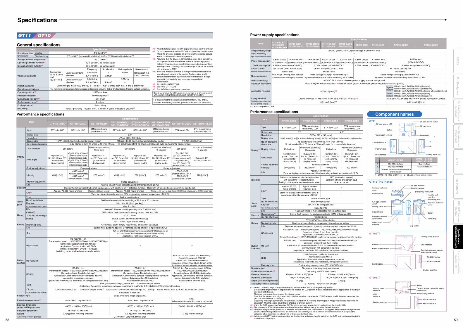
GT11 GT10
General specificationsItem
Operating ambienttemperature
Vibration resistance
Impact resistance
Operating atmosphere
Operating altitude2
Installation location
Overvoltage category3
Contamination level4
Cooling method
Grounding
SpecificationDisplay
Other than display
Storage ambient temperature
Operating ambient humidity1
Storage ambient humidity1
0°C to 50°C5
0°C to 55°C (horizontal installation), 0°C to 50°C (vertical installation)5
-20°C to 60°C
10 to 90%RH, no condensation
10 to 90%RH, no condensation
Conforming to JIS B 3502 and IEC 61131-2 (147m/s2, 3 times each in X, Y and Z directions)
Free from oil mist, corrosive gases, flammable gases and excessive conductive dusts or direct sun beams (The same applies to unit storage.)
2000m or less
In control panel6
or lower
2 or less
Self-cooling
Type D grounding (100Ω or less). Connect to panel if unable to ground.7
Conforming to JIS B 3502 and IEC 61131-2
Under intermittent vibration
Under continuousvibration
Frequency
5 to 8.4Hz
8.4 to 150Hz
5 to 8.4Hz
8.4 to 150Hz
Half amplitude
3.5mm
–
1.75mm
––
Sweep count
10 times each in X,Y and Z directions
Acceleration
–
9.8m/s2
–
4.9m/s2
1 :2 :
3 :
4 :
5 :6 :7 :
Water bulb temperature for STN display type must be 39°C or lower.Do not operate or store the GOT unit in pressurized environments where the pressure exceeds 0m elevation atmospheric pressure, as this could result in abnormal operation.Assuming that the device is connected at some point between a public power distribution network and local system equipment. Category applies to devices that are supplied with power from fixed equipment. The surge withstand voltage is 2500V for devices with ratings up to 300V.Index that indicates the level of foreign conductive matter in the operating environment of the device. Contamination level 2 denotes contamination by non-conductive matter only, though momentary conductivity may occur due to occasional condensation.0 to 40°C for GT115MHSExcluding GT115MHSThe 5VDC type requires no grounding.
Display1
Backlight
Memory
Battery
Built-in interface
Weight
Buzzer output
Protective construction4
External dimensions(without USB port cover)
Panel cut dimensions
Screen sizeResolutionDisplay sizeNo. of displayed characters
Display colors
Type
• 350 [cd/m2](Hardware versions A and B)
• 380 [cd/m2](Hardware version C or later)
380 [cd/m2] 220 [cd/m2]220 [cd/m2]
• 350 [cd/m2](Hardware versions A and B)
• 380 [cd/m2](Hardware version C or later)
400 [cd/m2] 220 [cd/m2] 400 [cd/m2]
View angle
Contrast adjustment
Intensity
Intensity adjustment
Life8-step adjustment
Approx. 75,000 hours or more Approx. 75,000 hours or moreApprox. 75,000 hours or more
(Time for display intensity reaches 50% at operating ambient temperature of 25°C)Matrix resistive type
Max. 2 points1,000,000 times or more (operating force 0.98N or less)
100,000 times
GT11-50BAT type lithium battery512KB built-in SRAM (battery backup)
Clock data, alarm history, recipe data, time action set values
Compact flash slot, 1ch Connector shape: TYPE Application: Data transfer, data storage, GOT startup FAT16 format: max. 2GB, FAT32 format: not usable
Embedded in main unit
Single tone (tone length adjustable)
0.7 [kg] (excl. mounting brackets) 1.0 [kg] (main unit only)
164(W) × 135(H) × 56(D) [mm] 176(W) × 220(H) × 93(D) [mm]167(W) × 135(H) × 65(D) [mm]
153(W) × 121(H) [mm]
Front: IP67f In panel: IP2X Front: IP67f In panel: IP2XIP65f
(when external connection cable is connected)
Replacement guideline approx. 5 years (operating ambient temperature: 25°C)
USB (full-speed 12Mbps), device 1ch Connector shape: Mini-BApplication: Connection to personal computer (project data read/write, OS installation, FA transparent function)
3MB built-in flash memory (for saving project data and OS)
300 keys/screen (matrix consisting of 15 lines × 20 columns)
Approx. 50,000 hours (operating ambient temperature: 25°C)
Min. 16 × 16 [dots] (per key)
Cold-cathode fluorescent tube (not replaceable), with backlight OFF detection function. Backlight off time and screen save time can be set.
Life (No. of writings)
Life2
TypeNo. of touch keysKey size
Life
C drive3
D drive
RS-232
RS-422/485
RS-422/232
USB
CF cardOptional function board
Backed up dataLife
5.7"
QVGA: 320 × 240 [dots]115(W) × 86(H) [mm] (in horizontal display mode) 115(W) × 86(H) [mm] (in horizontal display mode) 115(W) × 86(H) [mm]
16-dot standard font: 20 chars. × 15 lines (2-byte) 12-dot standard font: 26 chars. × 20 lines (2-byte) (in horizontal display mode)
ItemSpecification
Performance specifications
GT1155-QTBDQGT1155-QTBDA
GT1150HS-QLBDGT1155-QSBDQGT1155-QSBDA
GT1150-QLBDQGT1150-QLBDA
TFT color LCD STN color LCDSTN monochrome(black/white) LCD
STN monochrome(black/white) LCD
153(W) × 121(H) [mm]
0.9 [kg] (excl. mounting brackets)
256 colors 256 colors256 colors
Approx. 54,000 hours or moreApprox. 54,000 hours or more Approx. 54,000 hours or more
Right/left: 70°, Up: 70°, Down: 50°
(in horizontaldisplay mode)
Right/left: 55°, Up: 65°, Down: 70°
(in horizontaldisplay mode)
• Right/left: 50°,Up: 50°, Down: 60°(Hardware versions A and B)
• Right/left: 55°,Up: 65°, Down: 70°
(Hardware version C or later)
Right/left: 45°, Up: 20°, Down: 40°
(in horizontaldisplay mode)
Right/left: 45°, Up: 20°, Down: 40°
(in horizontaldisplay mode)
• Right/left: 50°, Up: 50°, Down: 60°(Hardware versions A and B)(In horizontal display mode)
• Right/left: 55°, Up: 65°, Down: 70°(Hardware version C or later)(In horizontal display mode)
Right/left: 70°, Up: 70°, Down: 50°
(in horizontaldisplay mode)
Right/left: 45°, Up: 20°, Down: 40°
Monochrome (black/white)16 gray scale
Monochrome (black/white)16 gray scale
Monochrome (black/white)16 gray scale
16-step adjustment16-step adjustment–
1ch for QCPU (Q mode)/motion controller CPU (Q series) or1ch for QnA/ACPU/motion controller CPU (A series)
Application: For bus connection of PLC
RS-232, 1chTransmission speed: 115200/57600/38400/19200/9600/4800bps
Connector shape: D-sub 9-pin (male)Application: Connection to barcode reader/personal computer
(project data read/write, OS installation,FA transparent function, etc.)
RS-422/485, 1chTransmission speed: 115200/57600/38400/19200/9600/4800bps
Connector shape: D-sub 9-pin (female)Application: Communication with PLCs
Terminal resistance5: OPEN/110Ω/330Ω (switching by terminal resistance transfer switch)
RS-422/232, 1ch (Select one when using.)Transmission speed: 115200/
57600/38400/19200/9600/4800bpsConnector shape: Round type, 32-pin (male)Application: Communication with connected devices
RS-232, 1chTransmission speed: 115200/57600/38400/19200/9600/4800bps
Connector shape: D-sub 9-pin (male)Application: Communication with connected devices,
connection to personal computer(project data read/write, OS installation, FA transparent function, etc.)
RS-232, 1ch, Transmission speed: 115200/57600/38400/19200/9600/4800bps
Connector shape: Mini-DIN 6-pin (female)Application: Connection to personal computer
(project data read/write, OS installation,FA transparent function, etc.)
Bus
– –
–
–
– –
–
–
GT Works3 Version1.31H or later
No. of simultaneous touch points
Touch panel
GT1155HS-QSBD
STN color LCD
GT1150-QLBD
STN monochrome(black/white) LCD
GT1155-QSBD
STN color LCD
GT1155-QTBD
TFT color LCD
Specifications
Single-wireinstallation
Two-wireinstallation
0.14 to 1.5 [mm2], AWG26 to AWG16 (single wire)0.14 to 1.0 [mm2], AWG26 to AWG16 (stranded wire)0.25 to 0.5 [mm2], AWG24 to AWG20 (bar terminal with insulation sleeve)0.14 to 0.5 [mm2], AWG26 to AWG20 (single wire)0.14 to 0.2 [mm2], AWG26 to AWG24 (stranded wire)
Component namesGT11
GT115MHS (Handy)
GT105M
: GT115M-QMBDQ and GT115M-QMBDA do not have a reset switch.
GT1055-QSBD GT1050-QBBD GT1045-QSBD GT1040-QBBD
Display1
Backlight
Touchpanel
Memory
Battery
Built-in interface
Weight (excl. mounting brackets)
Applicable software package
Buzzer output
Protective construction4
External dimensions
Panel cut dimensions
Item
Performance specifications
Type
Screen sizeResolutionDisplay size
Display colors
View angle
Contrast adjustmentIntensity
Life
Life2
User memory3
Backed up dataLife
RS-422/485
RS-232
Memory board
USB
Life (No. of writings)
TypeNo. of touch keysKey sizeNo. of simultaneous touch points
Life
Specification
(Time for display intensity reaches 50% at operating ambient temperature of 25°C)
1,000,000 times or more (operating force 0.98N or less)
Built-in flash memory for saving project data (3 MB or less) and OS
100,000 times
GT11-50BAT type lithium battery
Clock data, alarm history, recipe data, time action set values
Replacement guideline approx. 5 years (operating ambient temperature: 25°C)
RS-422/485, 1ch Transmission speed: 115200/57600/38400/19200/9600/4800bpsConnector shape: D-sub 9-pin (female)Application: Communication with PLCs
Terminal resistance5: OPEN/110Ω/330Ω (switched by terminal resistance transfer switch)
RS-232, 1ch Transmission speed: 115200/57600/38400/19200/9600/4800bpsConnector shape: D-sub 9-pin (male)
Application: Communication with PLCs, connection with barcode readers,communication with personal computers
(project data read/write, OS installation, transparent function)
USB (full-speed 12Mbps), device 1chConnector shape: Mini-B
Application: Communication with personal computer(project data read/write, OS installation, transparent function)
For installing memory board (GT10-50FMB) 1ch
Single tone (tone length adjustable/none)
Conforming to IP67f (front panel)
164(W) × 135(H) × 56(D)[mm]
153(W) × 121(H)[mm]
0.7[kg]
139(W) × 112(H) × 41(D)[mm]
130(+1 -0)(W) × 103(+1 -0)(H)[mm]
0.45[kg]
GT Works3 Version1.31H or later
Matrix resistive type
Max. 50 keys/screen
Min. 16 × 16 [dots] (per key)
Max. 2 points
5.7" 4.7"
QVGA: 320 × 240 [dots]
115(W) × 86(H) [mm] (in horizontal display mode) 96(W) × 72(H) [mm] (in horizontal display mode)
16-dot standard font: 20 chars. × 15 lines (2-byte),12-dot standard font: 26 chars. × 20 lines (2-byte) (in horizontal display mode)
16-step adjustment
STN monochrome(blue/white) LCDSTN color LCD
STN monochrome(blue/white) LCDSTN color LCD
256 colorsMonochrome (blue/white)
16 gray scale 256 colorsMonochrome (blue/white)
16 gray scale
Right/left: 55°,Up: 65°, Down: 70°
(in horizontaldisplay mode)
380 [cd/m2] 260 [cd/m2] 150 [cd/m2] 300 [cd/m2]Approx. 50,000 hours
(Time for display contrast reaches 20% at operating ambient temperature of 25°C)
Cold-cathode fluorescent tube (not replaceable) with backlight OFF detection function.
Backlight off time and screen save time can be set.
LED (no need to replace)Backlight off time and screen save
time can be set.
Approx. 75,000 hours or more
Approx. 54,000 hours or more
–
–
Right/left: 45°,Up: 20°, Down: 40°
(in horizontaldisplay mode)
Right/left: 50°,Up: 40°, Down: 70°
(in horizontaldisplay mode)
Right/left: 45°,Up: 20°, Down: 40°
(in horizontaldisplay mode)
Input power supply voltage
Power supply specifications
Item
Input frequencyInput maximum apparent power
Power consumption
Inrush currentPermissible instantaneous failure time
Noise resistance
Withstand voltageInsulation resistance
Applicable wire size
Clamp terminalTightening torque (terminalblock's terminal screws)
Noise voltage 1000Vp-p, noise width 1µsby noise simulator with noise frequency 30 to 100Hz
Noise voltage 500Vp-p, noise width 1µsby noise simulator with noise frequency 25 to 60Hz
Noise voltage 1000Vp-p, noise width 1µsby noise simulator with noise frequency 30 to 100Hz
500VAC for 1 minute between power supply terminal and ground10MΩ or higher with an insulation resistance tester (500VDC between power supply terminal and ground)
9.84W or less(410mA/24VDC)
9.36W or less(390mA/24VDC)
9.84W or less(410mA/24VDC)
9.36W or less(390mA/24VDC)
11.16W or less(465mA/24VDC)
9.72W or less(405mA/24VDC)
7.92W or less(330mA/24VDC)
4.32W or less (180mA/24VDC) 5.04W or less (210mA/24VDC)
3.6W or less (150mA/24VDC)
2.9W or less (120mA/24VDC)4.32W or less (180mA/24VDC)15A or less (2ms, at max. load) 26A or less (4ms, at max. load) 15A or less (26.4V) 2ms
24VDC (+10%, -15%), ripple voltage of 200mV or less–
Within 10ms Within 5msWithin 5ms
1 : Excluding GT115MHS
–
RS-232 interfaceRS-422 interface
AB
Bus interfaceRS-232 interface
Terminal resistance transfer switch(inside cover)C –
Display, touch key
Memory board interface
Memory board interface
USB interface
RS-232 interface
RS-422 interface
Display, touch key
Emergency stop switch
CF card interface
RS-232 interface
Grip switch
With backlight off
GT115M-QMBDGT115M-QMBDQGT115M-QMBDA
No. of displayed characters
1 :
2 :3 :4 :
5 :
Battery
CF card access LED
Power supply terminal
CF card access switch
CF card cover
Reset switchC
A
B
USB interface
POWER LED
CF card interface
Hook for wall mounting
Rear face protective cover
Neck strap hook
Battery
Hand strap
Interface protective cover
USB interface
POWER LED
Key type selector switch
Operation switches (6 switches)
RS-422/232 interface
Display, touch key
Battery
Power supply terminal
POWER LED
Specification
GT1055-QSBD GT1050-QBBD GT1045-QSBD GT1040-QBBDGT1155-QTBDGT1155-QSBDGT1155HS-QSBD
GT1150-QLBDGT1150HS-QLBD
GT1155-QSBDQGT1155-QSBDA
GT1150-QLBDQGT1150-QLBDA
GT1155-QTBDQGT1155-QTBDA
0.75 to 2 [mm2]1
Clamp terminals for M3 screw RAV1.25-3, V2-N3A, FV2-N3A1 AI2.5-6BU, AI0.34-6TQ, AI0.5-6WH (made by Phoenix Contact)
0.5 to 0.8 [N·m]1 0.22 to 0.25 [N·m]
On LCD screens, bright dots (permanently lit) and black dots (not to be lit) generally appear. Because the large number of display elements exist on an LCD screen, it is not possible to reduce appearance of the bright and black dots to zero.Flickering may occur depending on the display colors.Note that the existence of bright and black dots is a standard characteristic of LCD screens, and it does not mean that the products are defective or damaged.Displaying one single screen for a long time can lead to burn-in, causing afterimages or image irregularities that could not disappear. Use the screen saver that is effective to prevent burn-in.Using the GOT screen save/backlight OFF functions prevents screen burn-in and extends the backlight life.The memory is ROM that permits overwriting of new data without having to delete the existing data.This does not guarantee protection in all users’ environments. The specification is not applied when the interface protective cover and rear face protective cover are removed. The unit may not be used in an environment where it is exposed to splashing oil or chemicals for a long time or it is soaked with oil mist.In the case of GOT multi-drop connection, set the terminal resistance transfer switch on the GOT main unit according to the connection configuration.
GT104M
Terminal resistance transfer switch(inside cover)
RS-232 interface
RS-422 interface
USB interface
Display, touch key
Power supply terminal
Battery
Terminal resistance transfer switch (inside cover)
Do not use or store the GOT under direct sun light or in an environment with excessively high temperature, dust, humidity or vibration.
Applicable software package
For inquiries relating to products which conform to UL, cUL, and CE directives and shipping directives, please contact your local sales office.
58 59
Fo
r Main
tenan
ceP
erson
nel
GT
10iQ
Platfo
rmFor Initial Startup &
Operations
Fo
r Desig
ners
Specifications,External D
imensions
ME
LSE
C P
rocessC
ontrolList of C
onnectableM
odels, etc.IN
DE
X
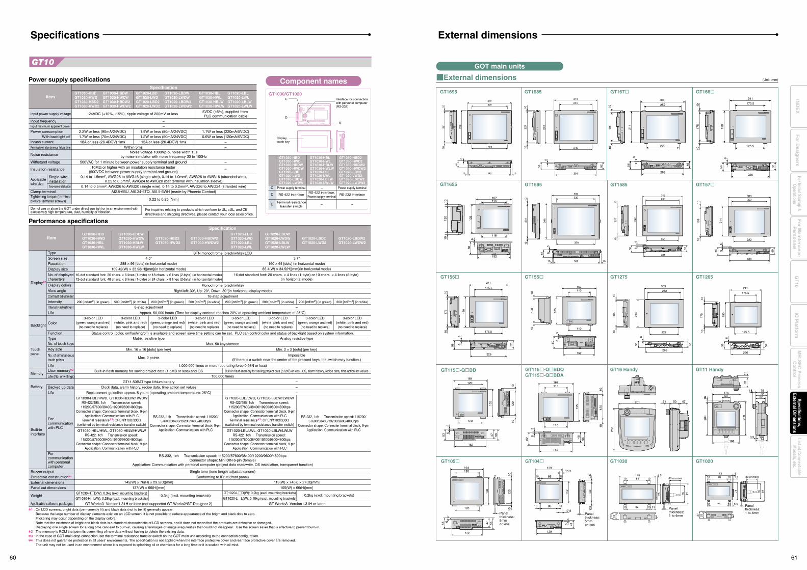
226
175.5
175.5
241
56
190
175
1010
5265
60
65
120
1010
152
135
167110
110
1362
176
1620
4
209
1683.5
74
6272
50
7518
303252
222
288
1010
4956
56
199
214
167110
135
110
152
120
1010
486562
5653 47
120
1010
152
135
164120
120
56
56
14584 1010
4.580 or more
10
2529.5
10 2184
846576
11310 76 10 7.5 80 or more
65
27 23
74 84
5
9.576 1010
303
252
214
222
1019
910
6
56
288
49
175.5
241
190
175.5
1010
175
656
226
52
9.5
9.5
102
129
415
10 86 10
13915.5
112
10 86 10
17.5
316
240
242
1010
227
301
56 52
6
296
320
61
6
38210 10
1028
110
397320
240
120
152
120
1010
135
47 56536
164120
397320
296
320
61 65
38210 10
1028
110
230
201 21 50 47
Panel thickness: 1 to 4mm
Panel thickness: 1 to 4mmPanel
thickness: 5mmor less
Panel thickness: 5mmor less
GT156 GT155 GT1275
GT1595 GT1585 GT157
GT1695
GT1655
GT1685 GT167 GT166
GT1265
GT11 HandyGT115-QBDQGT115-QBDA
GT16 HandyGT115-QBD
GT1020GT1030GT104GT105
301
250
316263
1010
56 6 52
5
227
242
116
116
152
167
135
60
120
10
610
Input power supply voltage
0.22 to 0.25 [N·m]
Power supply specifications
Item
Specification
Input frequencyInput maximum apparent power
Power consumption
Inrush current
Noise resistance
Withstand voltage
Insulation resistance
Permissible instantaneous failure time
Applicablewire size
Clamp terminalTightening torque (terminal block's terminal screws)
Noise voltage 1000Vp-p, noise width 1µsby noise simulator with noise frequency 30 to 100Hz
GT1030-HBDGT1030-HWDGT1030-HBD2GT1030-HWD2
GT1030-HBDWGT1030-HWDWGT1030-HBDW2GT1030-HWDW2
GT1020-LBDGT1020-LWDGT1020-LBD2GT1020-LWD2
GT1020-LBDWGT1020-LWDWGT1020-LBDW2GT1020-LWDW2
GT1030-HBLGT1030-HWLGT1030-HBLWGT1030-HWLW
GT1020-LBLGT1020-LWLGT1020-LBLWGT1020-LWLW
500VAC for 1 minute between power supply terminal and ground10MΩ or higher with an insulation resistance tester
(500VDC between power supply terminal and ground)
2.2W or less (90mA/24VDC)1.7W or less (70mA/24VDC)
1.9W or less (80mA/24VDC)1.2W or less (50mA/24VDC)
1.1W or less (220mA/5VDC)0.6W or less (120mA/5VDC)
13A or less (26.4DCV) 1ms18A or less (26.4DCV) 1ms
24VDC (+10%, -15%), ripple voltage of 200mV or less5VDC (±5%), supplied from PLC communication cable
Within 5ms––
––
–
–
0.14 to 1.5mm2, AWG26 to AWG16 (single wire), 0.14 to 1.0mm2, AWG26 to AWG16 (stranded wire),0.25 to 0.5mm2, AWG24 to AWG20 (bar terminal with insulation sleeve)
0.14 to 0.5mm2, AWG26 to AWG20 (single wire), 0.14 to 0.2mm2, AWG26 to AWG24 (stranded wire)
With backlight off
Single-wireinstallationTwo-wire installation
Built-in flash memory for saving project data (1.5MB or less) and OS Built-in flash memory for saving project data (512KB or less), OS, alarm history, recipe data, time action set values
GT1030-HBDGT1030-HWDGT1030-HBLGT1030-HWL
4.5" 3.7"
160 × 64 [dots] (in horizontal mode)
86.4(W) × 34.5(H)[mm](in horizontal mode)
288 × 96 [dots] (in horizontal mode)
109.42(W) × 35.98(H)[mm](in horizontal mode)
137(W) × 66(H)[mm]
0.3kg (excl. mounting brackets)
145(W) × 76(H) × 29.5(D)[mm]
105(W) × 66(H)[mm]
0.2kg (excl. mounting brackets)GT1020-LMD(W): 0.2kg (excl. mounting brackets)
GT1020-LML(W): 0.18kg (excl. mounting brackets)
113(W) × 74(H) × 27(D)[mm]
200 [cd/m2] (in green) 500 [cd/m2] (in white) 200 [cd/m2] (in green) 500 [cd/m2] (in white) 200 [cd/m2] (in green) 300 [cd/m2] (in white) 200 [cd/m2] (in green) 300 [cd/m2] (in white)
Matrix resistive type Analog resistive type
Min. 16 × 16 [dots] (per key) Min. 2 × 2 [dots] (per key)
Max. 2 pointsImpossible
(If there is a switch near the center of the pressed keys, the switch may function.)
16-dot standard font: 36 chars. × 6 lines (1-byte) or 18 chars. × 6 lines (2-byte) (in horizontal mode)12-dot standard font: 48 chars. × 8 lines (1-byte) or 24 chars. × 8 lines (2-byte) (in horizontal mode)
8-step adjustment –
–
–
–
16-dot standard font: 20 chars. × 4 lines (1-byte) or 10 chars. × 4 lines (2-byte) (in horizontal mode)
GT1030-HBD2GT1030-HWD2
GT1020-LBD2GT1020-LWD2
GT1020-LBDGT1020-LWDGT1020-LBLGT1020-LWL
GT1030-HBDWGT1030-HWDWGT1030-HBLWGT1030-HWLW
GT1030-HBDW2GT1030-HWDW2
GT1030-HBD/HWD, GT1030-HBDW/HWDWRS-422/485, 1ch Transmission speed: 115200/57600/38400/19200/9600/4800bps
Connector shape: Connecter terminal block, 9-pinApplication: Communication with PLC
Terminal resistance3: OPEN/110Ω/330Ω (switched by terminal resistance transfer switch)
GT1030-HBL/HWL, GT1030-HBLW/HWLWRS-422, 1ch Transmission speed:
115200/57600/38400/19200/9600/4800bpsConnector shape: Connector terminal block, 9-pin
Application: Communication with PLC
GT1030-HMD(W): 0.3kg (excl. mounting brackets)
GT1030-HML(W): 0.28kg (excl. mounting brackets)
GT1020-LBL/LWL, GT1020-LBLW/LWLWRS-422 1ch Transmission speed:
115200/57600/38400/19200/9600/4800bpsConnector shape: Connector terminal block, 9-pin
Application: Communication with PLC
RS-232, 1ch Transmission speed: 115200/57600/38400/19200/9600/4800bps
Connector shape: Connecter terminal block, 9-pinApplication: Communication with PLC
GT1020-LBD/LWD, GT1020-LBDW/LWDWRS-422/485 1ch Transmission speed: 115200/57600/38400/19200/9600/4800bps
Connector shape: Connector terminal block, 9-pinApplication: Communication with PLC
Terminal resistance3: OPEN/110Ω/330Ω (switched by terminal resistance transfer switch)
RS-232, 1ch Transmission speed: 115200/57600/38400/19200/9600/4800bps
Connector shape: Connecter terminal block, 9-pinApplication: Communication with PLC
Display1
Backlight
Touchpanel
Memory
Battery
Built-in interface
Weight
Applicable software packages
Buzzer outputProtective construction4
External dimensionsPanel cut dimensions
Item
Performance specifications
Type
Screen size
Resolution
Display size
No. of displayed characters
Display colors
View angle
Contrast adjustment
Intensity
Intensity adjustment
Life
Color
Function
User memory2
Backed up data
Life
For communication with PLC
For communicationwith personal computer
Life (No. of writings)
TypeNo. of touch keys
Key size
No. of simultaneous touch points
Life
STN monochrome (black/white) LCD
Monochrome (black/white)
Right/left: 30°, Up: 20°, Down: 30°(in horizontal display mode)
16-step adjustment
Approx. 50,000 hours (Time for display contrast reaches 20% at operating ambient temperature of 25°C)
3-color LED(green, orange and red)
(no need to replace)
3-color LED(white, pink and red)
(no need to replace)
3-color LED(green, orange and red)
(no need to replace)
3-color LED(white, pink and red)
(no need to replace)
3-color LED(green, orange and red)
(no need to replace)
3-color LED(white, pink and red)
(no need to replace)
3-color LED(green, orange and red)
(no need to replace)
3-color LED(white, pink and red)
(no need to replace)
Status control (color, on/flashing/off) is available and screen save time setting can be set. PLC can control color and status of backlight based on system information.
Max. 50 keys/screen
1,000,000 times or more (operating force 0.98N or less)
100,000 times
RS-232, 1ch Transmission speed: 115200/57600/38400/19200/9600/4800bpsConnector shape: Mini DIN 6-pin (female)
Application: Communication with personal computer (project data read/write, OS installation, transparent function)
Single tone (tone length adjustable/none)
Conforming to IP67f (front panel)
GT Works3 Version1.31H or laterGT Works3 Version1.31H or later (not supported GT Works2/GT Designer 2)
Specification
GT11-50BAT type lithium battery
Clock data, alarm history, recipe data, time action set values
Replacement guideline approx. 5 years (operating ambient temperature: 25°C)
GT1020-LBDWGT1020-LWDWGT1020-LBLWGT1020-LWLW
GT1020-LBDW2GT1020-LWDW2
Component names
GT1030/GT1020
Power supply terminal–RS-422 interface,
Power supply terminalRS-232 interface
GT1030-HBLGT1030-HWLGT1030-HBLWGT1030-HWLWGT1020-LBLGT1020-LWLGT1020-LBLWGT1020-LWLW
GT1030-HBD2GT1030-HWD2GT1030-HBDW2GT1030-HWDW2GT1020-LBD2GT1020-LWD2GT1020-LBDW2GT1020-LWDW2
C
DAI2.5-6BU, AI0.34-6TQ, AI0.5-6WH (made by Phoenix Contact)
1 :
2 :3 :4 :
On LCD screens, bright dots (permanently lit) and black dots (not to be lit) generally appear. Because the large number of display elements exist on an LCD screen, it is not possible to reduce appearance of the bright and black dots to zero.Flickering may occur depending on the display colors.Note that the existence of bright and black dots is a standard characteristic of LCD screens, and it does not mean that the products are defective or damaged.Displaying one single screen for a long time can lead to burn-in, causing afterimages or image irregularities that could not disappear. Use the screen saver that is effective to prevent burn-in.The memory is ROM that permits overwriting of new data without having to delete the existing data.In the case of GOT multi-drop connection, set the terminal resistance transfer switch on the GOT main unit according to the connection configuration.This does not guarantee protection in all users’ environments. The specification is not applied when the interface protective cover and rear face protective cover are removed.The unit may not be used in an environment where it is exposed to splashing oil or chemicals for a long time or it is soaked with oil mist.
Power supply terminal
RS-422 interface
– –ETerminal resistance
transfer switch
GT1030-HBDGT1030-HWDGT1030-HBDWGT1030-HWDWGT1020-LBDGT1020-LWDGT1020-LBDWGT1020-LWDW
Specifications
External dimensions (Unit: mm)
GOT main units
External dimensions
E
D
Interface for connection with personal computer (RS-232)
C
Display, touch key
Do not use or store the GOT under direct sun light or in an environment with excessively high temperature, dust, humidity or vibration.
241
175.5
190
175.51017
5 10
226
6
5258
303
252
222
288
53
1019
910
6
214
51
For inquiries relating to products which conform to UL, cUL, and CE directives and shipping directives, please contact your local sales office.
60 61
Fo
r Main
tenan
ceP
erson
nel
GT
10iQ
Platfo
rmFor Initial Startup &
Operations
Fo
r Desig
ners
Specifications,External D
imensions
ME
LSE
C P
rocessC
ontrolList of C
onnectableM
odels, etc.IN
DE
X
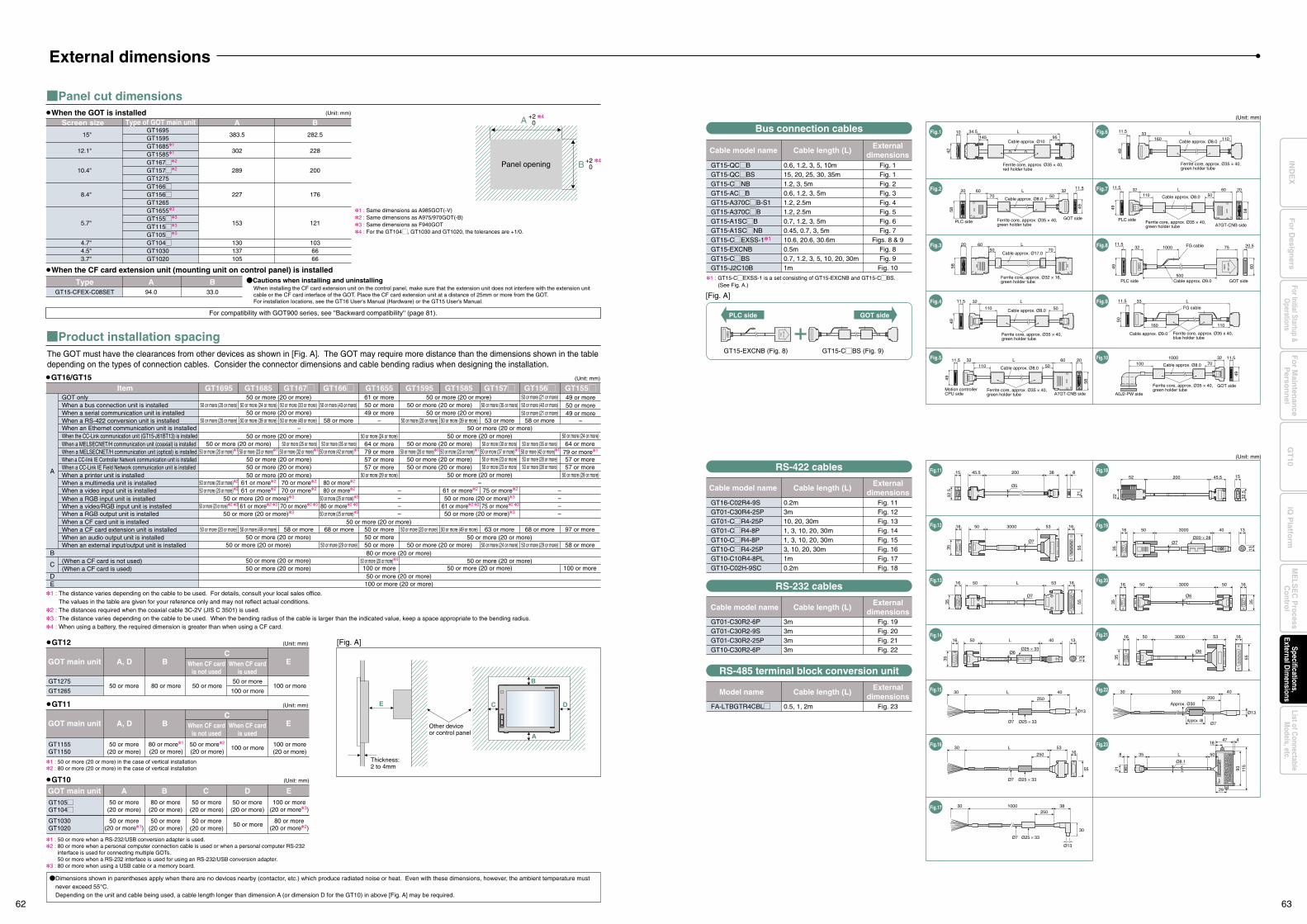
Panel cut dimensions
Product installation spacingThe GOT must have the clearances from other devices as shown in [Fig. A]. The GOT may require more distance than the dimensions shown in the table depending on the types of connection cables. Consider the connector dimensions and cable bending radius when designing the installation.
A +2 0
B +2 0Panel opening
Other device or control panel
E
Thickness: 2 to 4mm
GT15-QCMBGT15-QCMBSGT15-CMNBGT15-ACMBGT15-A370CMB-S1GT15-A370CMBGT15-A1SCMBGT15-A1SCMNBGT15-CMEXSS-11
GT15-EXCNBGT15-CMBSGT15-J2C10B
1 : GT15-CMEXSS-1 is a set consisting of GT15-EXCNB and GT15-CMBS. (See Fig. A.)
GT15-EXCNB (Fig. 8) GT15-CMBS (Fig. 9)
(Unit: mm)
PLC side GOT side
Cable model name
0.6, 1.2, 3, 5, 10m15, 20, 25, 30, 35m1.2, 3, 5m0.6, 1.2, 3, 5m1.2, 2.5m1.2, 2.5m0.7, 1.2, 3, 5m0.45, 0.7, 3, 5m10.6, 20.6, 30.6m0.5m0.7, 1.2, 3, 5, 10, 20, 30m1m
Fig. 1Fig. 1Fig. 2Fig. 3Fig. 4Fig. 5Fig. 6Fig. 7
Figs. 8 & 9Fig. 8Fig. 9
Fig. 10
Cable length (L)External
dimensions
Fig.1 Fig.6
Fig.2 Fig.7
Fig.3 Fig.8
Fig.4 Fig.9
Fig.5 Fig.10
Bus connection cables
Ferrite core, approx. Ø35 × 40,green holder tube
A0J2-PW side
GOT side
Cable approx. Ø8.0
100070
32 11.5
49
100
11.532
49
CO
N1
1000 FG cable
500Cable approx. Ø9.0PLC side GOT side
CO
N2
GO
T side 60
75 20.5
11.5 32110
L50
60 20
49
58
Ferrite core, approx. Ø35 × 40,green holder tube
Motion controllerCPU side A7GT-CNB side
Cable approx. Ø8.0
11.5 32
110
49
L
Cable approx. Ø8.0
Ferrite core, approx. Ø35 × 40,green holder tube
50
20 60 L50
Cable approx. Ø17.070
Ferrite core, approx. Ø32 × 16,green holder tube
58
11.5
49
33160
L
Cable approx. Ø8.0110
Ferrite core, approx. Ø35 × 40,green holder tube
20 60
58
70Cable approx. Ø8.0
Ferrite core, approx. Ø35 × 40,green holder tube
PLC sideGOT side
5032
11.5
49
L
11.5
50
33 L
Cable approx. Ø9.0
FG cable
Ferrite core, approx. Ø35 x 40,blue holder tube
110160
CO
N1
CO
N2
GO
T side
(Unit: mm)
A B
AScreen size Type of GOT main unit
Type
B
Cautions when installing and uninstalling
15"
12.1"
10.4"
8.4"
5.7"
4.7"4.5"3.7"
383.5
302
289
227
153
130137105
94.0GT15-CFEX-C08SET 33.0
282.5
228
200
176
121
1036666
GT1695GT1595GT16851
GT15851
GT167M2
GT157M2
GT1275GT166MGT156MGT1265GT16553
GT155M3
GT115M3
GT105M3
GT104MGT1030GT1020
When installing the CF card extension unit on the control panel, make sure that the extension unit does not interfere with the extension unit cable or the CF card interface of the GOT. Place the CF card extension unit at a distance of 25mm or more from the GOT.For installation locations, see the GT16 User's Manual (Hardware) or the GT15 User's Manual.
4
4
(Unit: mm)
A
B
GT1695 GT1685 GT167M GT166MItem
C
DE
When the GOT is installed
When the CF card extension unit (mounting unit on control panel) is installed
GT16/GT15
GOT onlyWhen a bus connection unit is installedWhen a serial communication unit is installedWhen a RS-422 conversion unit is installedWhen an Ethernet communication unit is installedWhen the CC-Link communication unit (GT15-J61BT13) is installed
When a CC-link IE Controller Network communication unit is installedWhen a CC-Link IE Field Network communication unit is installed
When a MELSECNET/H communication unit (coaxial) is installedWhen a MELSECNET/H communication unit (optical) is installed
When a printer unit is installed
When a video input unit is installedWhen a RGB input unit is installedWhen a video/RGB input unit is installedWhen a RGB output unit is installedWhen a CF card unit is installedWhen a CF card extension unit is installedWhen an audio output unit is installedWhen an external input/output unit is installed
When a multimedia unit is installed
(When a CF card is not used)(When a CF card is used)
50 or more (20 or more) 50 or more (24 or more)
50 or more (20 or more)
50 or more (20 or more)
80 or more (20 or more)50 or more (20 or more)50 or more (20 or more)
50 or more (20 or more)100 or more (20 or more)
50 or more (20 or more) 61 or more50 or more49 or more
50 or more (20 or more)
50 or more (20 or more)
64 or more79 or more57 or more57 or more
50 or more (29 or more)
–50 or more (20 or more)
–
GT1595GT1655 GT1585 GT157M GT156M GT155M
50 or more (20 or more)
50 or more (20 or more)50 or more (20 or more)
50 or more (20 or more)50 or more (20 or more)
50 or more (20 or more)
50 or more (20 or more)
50 or more (23 or more) 50 or more (28 or more)50 or more (23 or more) 50 or more (28 or more)
57 or more57 or more
50 or more (20 or more) 50 or more (20 or more)50 or more (29 or more) 50 or more (24 or more) 50 or more (29 or more) 58 or more
50 or more (20 or more)4 50 or more (20 or more)100 or more 100 or more50 or more (20 or more)
68 or more 63 or more50 or more (20 or more)
68 or more50 or more (20 or more)50 or more50 or more50 or more
50 or more (49 or more)50 or more (20 or more) 50 or more (49 or more) 58 or more 97 or more
50 or more (20 or more) 50 or more (20 or more)50 or more (35 or more)50 or more (25 or more) 50 or more (30 or more) 50 or more (35 or more) 64 or more50 or more (24 or more)
50 or more (20 or more) 50 or more (29 or more)
49 or more
–
50 or more (21 or more)50 or more50 or more (40 or more)50 or more (20 or more) 50 or more (24 or more) 50 or more (33 or more) 50 or more (43 or more) 50 or more (20 or more) 50 or more (35 or more)
79 or more150 or more (42 or more)150 or more (20 or more)1 50 or more (23 or more)1 50 or more (32 or more)1 50 or more (42 or more)1
50 or more (20 or more)2 61 or more2 70 or more2 80 or more2
50 or more (20 or more)2
50 or more (20 or more)361 or more2 70 or more2 80 or more2 61 or more2 75 or more2
50 or more (20 or more)1 50 or more (23 or more)1 50 or more (37 or more)1
––
50 or more (25 or more)3 ––
50 or more (20 or more)2 3 61 or more2 3 70 or more2 3 80 or more2 3 61 or more2 3 75 or more2 3– –50 or more (20 or more)3 –
50 or more (20 or more)3 50 or more (25 or more)3 – 50 or more (20 or more)3 –
58 or more50 or more (20 or more) 50 or more (39 or more) 50 or more (48 or more) 58 or more 50 or more (20 or more) 50 or more (39 or more) 53 or more49 or more50 or more (21 or more)
(Unit: mm)
50 or more(20 or more)
100 or more(20 or more)
100 or more80 or more1
(20 or more)50 or more2
(20 or more)GT1155GT1150
GOT main unit A, D EBC
When CF cardis not used
When CF cardis used
1 : 50 or more (20 or more) in the case of vertical installation2 : 80 or more (20 or more) in the case of vertical installation
1 : 50 or more when a RS-232/USB conversion adapter is used.2 : 80 or more when a personal computer connection cable is used or when a personal computer RS-232
interface is used for connecting multiple GOTs.50 or more when a RS-232 interface is used for using an RS-232/USB conversion adapter.
3 : 80 or more when using a USB cable or a memory board.
GT1030GT1020
GT105MGT104M
(Unit: mm)
50 or more(20 or more1)
80 or more(20 or more2)
50 or more50 or more
(20 or more)50 or more
(20 or more)
50 or more(20 or more)
50 or more(20 or more)
100 or more(20 or more3)
80 or more(20 or more)
50 or more(20 or more)
GOT main unit A EB C D
GT11
GT10
11.5 32110 Cable approx. Ø8.0
L50
60 20
49
Ferrite core, approx. Ø35 × 40,green holder tube
PLC sideA7GT-CNB side
58
(Unit: mm)
GT16-C02R4-9SGT01-C30R4-25PGT01-CMR4-25PGT01-CMR4-8PGT10-CMR4-8PGT10-CMR4-25PGT10-C10R4-8PLGT10-C02H-9SC
Cable model name
0.2m3m10, 20, 30m1, 3, 10, 20, 30m1, 3, 10, 20, 30m3, 10, 20, 30m1m0.2m
Fig. 11Fig. 12Fig. 13Fig. 14Fig. 15Fig. 16Fig. 17Fig. 18
Cable length (L)External
dimensions
GT01-C30R2-6PGT01-C30R2-9SGT01-C30R2-25PGT10-C30R2-6P
Cable model name
3m3m3m3m
Fig. 19Fig. 20Fig. 21Fig. 22
Fig. 23
Cable length (L)External
dimensions
Externaldimensions
Fig.12
Fig.13
Fig.14
Fig.15
Fig.16
Fig.11RS-422 cables
RS-232 cables
FA-LTBGTR4CBLM
Model name
0.5, 1, 2m
Cable length (L)
RS-485 terminal block conversion unit
5016
35
53 16
55
3000
Ø7
16 50 53L
35 55
Ø7
16
Ø25 × 33Ø6
50 4016
35
13
13
L16 50 533000
35
16
55
Ø6
16 50 503000
35
16
35
Ø6
16 50 40 13
13
3000
35
Ø7Ø20 × 28
30 L 40
250
Ø7 Ø25 × 33
Ø13
30 L 53
Ø7
55
16
Ø25 × 33
250
30 3000 40200
Approx. 48Ø7
Ø13
Approx. Ø30
15 845.5 38200
32.5
21
Ø5
50
4718
4
29
115
Ø8.1
35
9321
8 L
[Fig. A]
1 : Same dimensions as A985GOT(-V)2 : Same dimensions as A975/970GOT(-B)3 : Same dimensions as F940GOT4 : For the GT104M, GT1030 and GT1020, the tolerances are +1/0.
1 : The distance varies depending on the cable to be used. For details, consult your local sales office.The values in the table are given for your reference only and may not reflect actual conditions.
2 : The distances required when the coaxial cable 3C-2V (JIS C 3501) is used.3 : The distance varies depending on the cable to be used. When the bending radius of the cable is larger than the indicated value, keep a space appropriate to the bending radius.4 : When using a battery, the required dimension is greater than when using a CF card.
Dimensions shown in parentheses apply when there are no devices nearby (contactor, etc.) which produce radiated noise or heat. Even with these dimensions, however, the ambient temperature must never exceed 55°C. Depending on the unit and cable being used, a cable length longer than dimension A (or dimension D for the GT10) in above [Fig. A] may be required.
(Unit: mm)
50 or more 100 or more50 or more
100 or more80 or more 50 or more
GT1275
GT1265
GOT main unit A, D EBC
When CF cardis not used
When CF cardis used
GT12
For compatibility with GOT900 series, see ''Backward compatibility'' (page 81).
145L
95Cable approx. Ø10
Ferrite core, approx. Ø35 × 40,red holder tube
10
42
34.5
External dimensions
A
B
C D
Fig.17 30 1000 38
Ø13
Ø25 × 33Ø7
30
250
Fig.18
Fig.19
Fig.22
Fig.23
Fig.20
Fig.21
52
22 32.5
200 45.5 15
[Fig. A]
62 63
Fo
r Main
tenan
ceP
erson
nel
GT
10iQ
Platfo
rmFor Initial Startup &
Operations
Fo
r Desig
ners
Specifications,External D
imensions
ME
LSE
C P
rocessC
ontrolList of C
onnectableM
odels, etc.IN
DE
X
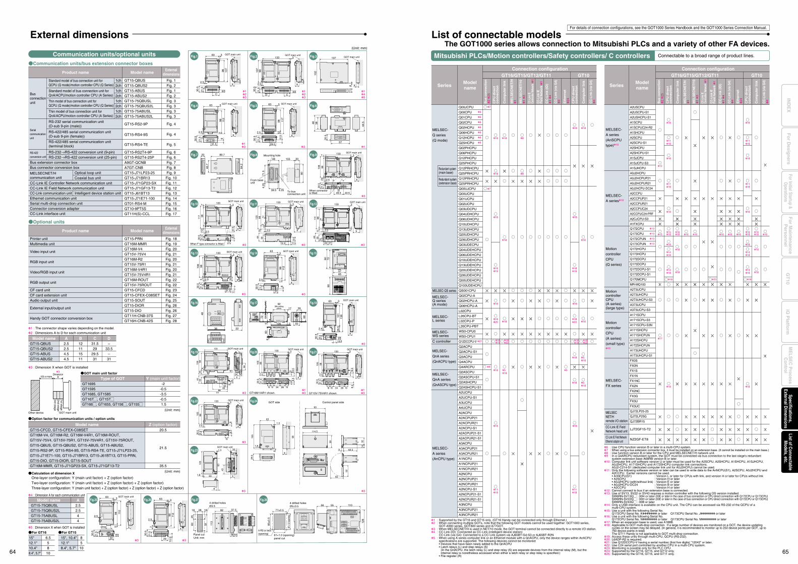
1 : Supported by the GT16 and GT15 only. (GT16 Handy can be connected only through Ethernet.)2 : When connecting multiple GOTs, note that the following GOT models cannot be used together: GOT1000 series,
GOT-A900 series, GOT800 series and A77GOT.3 : When MELSECNET/H is used in NET/10 mode, the GOT terminal cannot be connected directly to a remote I/O station.4 : CC-Link (ID): Connected as CC-Link (intelligent device station) CC-Link (via G4): Connected to a CC-Link system via AJ65BT-G4-S3 or AJ65BT-R2N5 : When using A series computer link or an Ethernet module with a QnACPU, only the device ranges within AnACPU
specifications are supported. The following devices cannot be monitored: • Devices that have been newly added to the QnACPU • Latch relays (L) and step relays (S)
(In the QnACPU, the latch relay (L) and step relay (S) are separate devices from the internal relay (M), but the internal relay is nonetheless accessed when either a latch relay or step relay is specified.)
• File register (R)
6 : Use CPU function version B or later in a multi-CPU system.7 : When using a bus extension connector box, it must be installed on an extension base. (It cannot be installed on the main base.)8 : Use function version B or later for the CPU and MELSECNET/H network unit.9 : In a Q4ARCPU redundant system, the GOT must be connected via bus connection to the last stage's redundant
system extension base A68RB version B or later.10 : Computer link unit software version U or later must be used for the A2SCPU, A2SHCPU, A1SHCPU, A1SJHCPU, A0J2HCPU, A171SHCPU and A172SHCPU computer link connections. A0J2-C214-S1 (dedicated computer link unit for A0J2HCPU) cannot be used.11 : Only the following software version or later can be used to write data to the AnNCPU(S1), A2SCPU, A0J2HCPU and
A2CCPU. Earlier versions cannot be used. • AnNCPU(S1) : Version L or later for CPUs with link, and version H or later for CPUs without link • A2SCPU : Version H or later • A0J2HCPU (with/without link) : Version E or later • A0J2HCPU-DC24 : Version B or later • A2CCPU : Version H or later12 : Cannot connect to bus if an extension base is connected.13 : Use of SV13, SV22 or SV43 requires a motion controller with the following OS version installed. SW6RN-SV13QM : 00H or later (00E or later in the case of bus connection or CPU direct connection with Q172CPU or Q173CPU) SW6RN-SV22QM : 00H or later (00E or later in the case of bus connection or CPU direct connection with Q172CPU or Q173CPU) SW6RN-SV43QM : 00B or later14 : Only a USB interface is available on the CPU unit. The CPU can be accessed via RS-232 of the QCPU of a
multi-CPU system.15 : Use a unit with the following Serial No. Q172CPU Serial No. K or later Q173CPU Serial No. J or later16 : Use a unit with the following Serial No. Q172CPU Serial No. N or later Q173CPU Serial No. M or later17 : When an expansion base is used, use A168B.18 : Applicable to GOT multi-drop connection. If a large number of devices are monitored on a GOT, the device updating
cycles on the screen may be delayed. (In general, it is recommended to monitor up to 250 device points per GOT, up to 750 device points in total)
The GT11 Handy is not applicable to GOT multi-drop connection.19 : Access these units through multi-CPU, QCPU (RS-232).20 : L6ADP-R2 is required.21 : Use Q12DCCPU-V having a serial number (first five digits) "12042" or later.22 : Use C24 serial port controlled by another CPU in a multi-CPU system.23 : Monitoring is possible only for the PLC CPU.24 : Supported by the GT16, GT15, and GT12 only.25 : Supported by the GT16, GT15, and GT11 only.
Q00JCPU
Q00CPU
Q01CPU
Q02CPU
Q02HCPU
Q06HCPU
Q12HCPU
Q25HCPU
Q02PHCPU
Q06PHCPU
Q12PHCPU
Q25PHCPU
Q12PRHCPU
Q25PRHCPU
Q12PRHCPU
Q25PRHCPU
Q00UJCPU
Q00UCPU
Q01UCPU
Q02UCPU
Q03UDCPU
Q04UDHCPU
Q06UDHCPU
Q10UDHCPU
Q13UDHCPU
Q20UDHCPU
Q26UDHCPU
Q03UDECPU
Q04UDEHCPU
Q06UDEHCPU
Q10UDEHCPU
Q13UDEHCPU
Q20UDEHCPU
Q26UDEHCPU
Q50UDEHCPU
Q100UDEHCPU
QS001CPU
Q02CPU-A
Q02HCPU-A
Q06HCPU-A
L02CPU
L26CPU-BT
L02CPU-P
L26CPU-PBT
WS0-CPU0
WS0-CPU1
Q12DCCPU-V
Q2ACPU
Q2ACPU-S1
Q3ACPU
Q4ACPU
Q4ARCPU
Q2ASCPU
Q2ASCPU-S1
Q2ASHCPU
Q2ASHCPU-S1
A2UCPU
A2UCPU-S1
A3UCPU
A4UCPU
A2ACPU
A2ACPUP21
A2ACPUR21
A2ACPU-S1
A2ACPUP21-S1
A2ACPUR21-S1
A3ACPU
A3ACPUP21
A3ACPUR21
A1NCPU
A1NCPUP21
A1NCPUR21
A2NCPU
A2NCPUP21
A2NCPUR21
A2NCPU-S1
A2NCPUP21-S1
A2NCPUR21-S1
A3NCPU
A3NCPUP21
A3NCPUR21
A2USCPU
A2USCPU-S1
A2USHCPU-S1
A1SCPU
A1SCPUC24-R2
A1SHCPU
A2SCPU
A2SCPU-S1
A2SHCPU
A2SHCPU-S1
A1SJCPU
A1SJCPU-S3
A1SJHCPU
A0J2HCPU
A0J2HCPUP21
A0J2HCPUR21
A0J2HCPU-DC24
A2CCPU
A2CCPUP21
A2CCPUR21
A2CCPUC24
A2CCPUC24-PRF
A2CJCPU-S3
A1FXCPU
Q172CPU
Q173CPU
Q172CPUN
Q173CPUN
Q172HCPU
Q173HCPU
Q172DCPU
Q173DCPU
Q172DCPU-S1
Q173DCPU-S1
Q170MCPU
MR-MQ100
A273UCPU
A273UHCPU
A273UHCPU-S3
A373UCPU
A373UCPU-S3
A171SCPU
A171SCPU-S3
A171SCPU-S3N
A171SHCPU
A171SHCPUN
A172SHCPU
A172SHCPUN
A173UHCPU
A173UHCPU-S1
FX0S
FX0N
FX1S
FX1N
FX1NC
FX2N
FX2NC
FX3G
FX3U
FX3UC
QJ72LP25-25
QJ72LP25G
QJ72BR15
LJ72GF15-T2
NZ2GF-ET8
6
7
7
818 18
18 18
18
18
12
1118
18
1118
18
18
18
18
18
18 18
1118
1118
13
13 15
17
1518
1618
1618
1618
1418 18
1418
18
181418
18
18
18 23
1418 18
18
16 16 16 16 16 16
13
13
818
18
18 18
1819
1819
18
181820 18
1820
18
1818
9
1819
182221
518
1118
1118
5
18 518
18 518
6
6
6
6
6
6
MELSEC-
Q series
(Q mode)
MELSEC-QS series
MELSEC-Q series (A mode)
MELSEC-L series
MELSEC-WS series
C controller
MELSEC-
QnA series
(QnACPU type)
MELSEC-
QnA series
(QnASCPU type)
Redundant system(extension base)
Redundant system (main base)
MELSEC-
A series
(AnSCPU
type)10
MELSEC-
A series10
Motion controller CPU (A series)(large type)
Motion
controller
CPU
(A series)
(small type)10
MELSEC-
FX series
MELSECNET/Hremote I/O station
CC-Link IE Field Network head unit
CC-Link IE Field NetworkEthernet adaptor unit
MELSEC-
A series
(AnCPU type)
1819
1822
Motion
controller
CPU
(Q series)
Mitsubishi PLCs/Motion controllers/Safety controllers/ C controllers Connectable to a broad range of product lines.
GT10
The GOT1000 series allows connection to Mitsubishi PLCs and a variety of other FA devices.
Bus
con
nect
ion
2
25
CP
U d
irec
tco
nn
ecti
on
ME
LS
EC
NE
T/H
1
CC
-Lin
k (I
D)
1
4
CC-L
ink
IE
Fiel
d Ne
twor
k
1
CC-L
ink IE
Cont
rolle
r Netw
ork
1
CC
-Lin
k (v
ia G
4)
4
CC
-Lin
k (v
ia G
4)
4
Eth
ern
et
24
Co
mp
ute
r lin
k
CP
U d
irec
tco
nn
ecti
on
Co
mp
ute
r lin
k
Connection configurationGT16/GT15/GT12/GT11 GT10
Bus
con
nect
ion
2
25
CP
U d
irec
tco
nn
ecti
on
ME
LSE
CN
ET/
10
1
3
ME
LSE
CN
ET/
H
1
CC
-Lin
k (I
D)
1
4
CC-L
ink I
ECo
ntro
ller N
etwo
rk
1
CC
-Lin
k IE
Fi
eld
Net
wor
k
1
CC
-Lin
k (v
ia G
4)
4
CC
-Lin
k (v
ia G
4)
4
Eth
ern
et
24
Co
mp
ute
r lin
k
CP
U d
irec
tco
nn
ecti
on
Co
mp
ute
r lin
k
SeriesModelname Series
Modelname
For details of connection configurations, see the GOT1000 Series Handbook and the GOT1000 Series Connection Manual.
List of connectable models
Connection configurationGT16/GT15/GT12/GT11
ME
LSE
CN
ET/
10
1
3
(Unit: mm)
(Unit: mm)
Product name
Standard model of bus connection unit forQCPU (Q mode)/motion controller CPU (Q Series)
Standard model of bus connection unit forQnA/ACPU/motion controller CPU (A Series)
Thin model of bus connection unit forQCPU (Q mode)/motion controller CPU (Q Series)
Thin model of bus connection unit forQnA/ACPU/motion controller CPU (A Series)
RS-232 serial communication unit (D-sub 9-pin (male))
RS-422/485 serial communication unit(D-sub 9-pin (female))
RS-422/485 serial communication unit (terminal block)
RS-232→RS-422 conversion unit (9-pin)RS-232→RS-422 conversion unit (25-pin)
Bus extension connector boxBus connector conversion box
Optical loop unitCoaxial bus unit
CC-Link IE Controller Network communication unitCC-Link IE Field Network communication unitCC-Link communication unit Intelligent device station unitEthernet communication unitSerial multi-drop connection unitConnector conversion adapterCC-Link interface unit
1ch2ch1ch2ch1ch2ch1ch2ch
GT15-QBUSGT15-QBUS2GT15-ABUSGT15-ABUS2GT15-75QBUSLGT15-75QBUS2LGT15-75ABUSLGT15-75ABUS2L
GT15-RS2-9P
GT15-RS4-9S
GT15-RS4-TE
GT15-RS2T4-9PGT15-RS2T4-25PA9GT-QCNBA7GT-CNBGT15-J71LP23-25GT15-J71BR13GT15-J71GP23-SXGT15-J71GF13-T2GT15-J61BT13GT15-J71E71-100GT01-RS4-MGT10-9PT5SGT11H(S)-CCL
Model name
Fig. 1Fig. 2Fig. 1Fig. 2Fig. 3Fig. 3Fig. 3Fig. 3
Fig. 4
Fig. 4
Fig. 5
Fig. 6Fig. 6Fig. 7Fig. 8Fig. 9
Fig. 10Fig. 11Fig. 12Fig. 13Fig. 14Fig. 15Fig. 16Fig. 17
Externaldimensions
2.52.54.54.5
A12111511
B31.529
29.531
C–
33.5–
31
DGT15-QBUSGT15-QBUS2GT15-ABUSGT15-ABUS2
Model name
Fig.1 Fig.2 Fig.3
Fig.4 Fig.5 Fig.6
Fig.7 Fig.8 Fig.9
Fig.11 Fig.12
Fig.18
Fig.24
Fig.27
Fig.16
Fig.10
Fig.14
Fig.17
Fig.13
Fig.22
Fig.23
Communication units/optional units
Fig.15
Fig.21Fig.19 Fig.20
2.52.544
AGT15-75QBUSLGT15-75QBUS2LGT15-75ABUSLGT15-75ABUS2L
Model name4 : Dimension A for each communication unit
6.55810
15"12.1"10.4"8.4", 5.7"
For GT16
Option factor for communication units / option units
GOT main unit factor
Calculation of dimension X
For GT15
8510
15", 10.4"12.1"8.4", 5.7"
5 : Dimension X when GOT is installed
1 : The connector shape varies depending on the model.2 : Dimensions A to D for each communication unit
GOT main unit63 3
98
2.5
30.5
21.5
107
A
X
C
B
GOT main unit
A
X
133
107
30.5
21.5
2.5
98
3
C
B
D123
123
13 3 1
3
3
3
3
3
3
145
X
798 11
2
2.5
30.5
31.5
21.5
3 GOT main unit63
9
X
GOT main unit63 3
1298
2.5
30.5
21.5
117
29.5
11.5
Busconnectionunit
Serial communication unit
RS-422conversion unit
MELSECNET/Hcommunication unit
Communication units/bus extension connector boxes
Product name
GT15-PRNGT16M-MMRGT16M-V4GT15V-75V4GT16M-R2GT15V-75R1GT16M-V4R1GT15V-75V4R1GT16M-ROUTGT15V-75ROUTGT15-CFCDGT15-CFEX-C08SETGT15-SOUTGT15-DIORGT15-DIOGT11H-CNB-37SGT16H-CNB-42S
Model name
Fig. 18Fig. 19Fig. 20Fig. 21Fig. 20Fig. 21Fig. 20Fig. 21Fig. 22Fig. 22Fig. 23Fig. 24Fig. 25Fig. 26Fig. 26Fig. 27Fig. 28
Externaldimensions
Printer unitMultimedia unit
Video input unit
RGB input unit
Video/RGB input unit
RGB output unit
CF card unitCF card extension unitAudio output unit
External input/output unit
Handy GOT connector conversion box
Optional unitsX
GOT main unit
8.5
17
30.5
21.5
2.5(12)
117 98
7 1333
3
33
3
18
60 91 113
25
18 82 37.5
18 19.5
4 drilled holesØ3.5
28
Panel cutUnit: mm
137
102
A17
.5
GOT main unit
X
20.5
3848
57
RS-232
RS-422
20 89.7
64.2
46.7
48
39.5 4.25
20155
8071.5
4.25
Mounting hole
From baseunit
To bus connection unit
30.5
7 3133
2.5 X
21.5
9.5
108
98(3
)
40.549.5
GOT main unit
X
GOT main unit
11
31.5
30.5
21.5
2.53 20
108
98
1333
2.5
21
3GOT main unit63
98 112
78
30.5
21.5
X
13GT15V-75V4R1 shown.
2.5
133
105
98
38
19.5
30.5
21.5
18 18 34 26 19 8.5
GOT main unit
X
93
114.5
9
60
62.5
1432
52
58
GOT main unit30
X
8
631.8
43
63
105
1.3
GOT main unit
101
28.5
1330.5
21.5
136
2.4
X
13.5
363
133
X
3
2
GOT main unit
120
44 35
23.5
9815
3
2.5
11.515.5
13GT16M-V4R1 shown.
105
30.5
21.5
98
19.5
8.5
88
133
2.5
18 18 34 26 19
3
X
GOT main unit
3
105
30.5
9821
.5
88.
5
133 3
2.5
19
X
GOT main unit
133
24X
128 98
9
148
26
38
2344 35
11186
4632
GOT main unit
Control panel sideGOT side
When F type connector is fitted
When connectoris fitted
Fig.28
3
44.5
(Unit: mm)
GT15-CFCD, GT15-CFEX-C08SETGT16M-V4, GT16M-R2, GT16M-V4R1, GT16M-ROUT, GT15V-75V4, GT15V-75R1, GT15V-75V4R1, GT15V-75ROUT, GT15-QBUS, GT15-QBUS2, GT15-ABUS, GT15-ABUS2, GT15-RS2-9P, GT15-RS4-9S, GT15-RS4-TE, GT15-J71LP23-25, GT15-J71E71-100, GT15-J71BR13, GT15-J61BT13, GT15-PRN, GT15-DIO, GT15-DIOR, GT15-SOUTGT16M-MMR, GT15-J71GP23-SX, GT15-J71GF13-T2
One-layer configuration: Y (main unit factor) + Z (option factor)Two-layer configuration: Y (main unit factor) + Z (option factor) + Z (option factor)Three-layer configuration: Y (main unit factor) + Z (option factor) + Z (option factor) + Z (option factor)
20.5
21.5
35.5
GT1695GT1595GT1685, GT1585GT167M, GT157MGT166M, GT1655, GT156M, GT155M
-2-0.5-3.5-0.5 1.5
Type of GOT Y (main unit factor)
Model name Z (option factor)
3 : Dimension X when GOT is installed
Other device
100 or more
GOT main unit
3Dimension
X
1st stage2nd stage3rd stage
57.5
126 2 50
39
72
464
808
92(Mounting
pitch) 17
68
57
7280
65
90
48
36 22
External dimensions
Fig.26Fig.25
5556
126
1104 drilled holesØ5±0.5
77±0.5
85±
0.5
87+1
,0 (op
ening
)
61+1.0 (opening)panel cut
4-R3 or less(opening)
1.3
1.8
6
98
29.5
63
105
X
63
2.5
29
112
98
7
30.5
21.5
10.5
X
3
(Mou
ntin
g pi
tch)
(Mou
ntin
g pi
tch)
2.5
Ø18
22
30.5
1321.5
63 3
985
110
GOT main unit
X
133 3
111
GOT main unit
X6 2.5
2
3519
44
2124
98
3
3
64 65
Fo
r Main
tenan
ceP
erson
nel
GT
10iQ
Platfo
rmFor Initial Startup &
Operations
Fo
r Desig
ners
Specifications,External D
imensions
ME
LSE
C P
rocessC
ontrolList of C
onnectableM
odels, etc.IN
DE
X
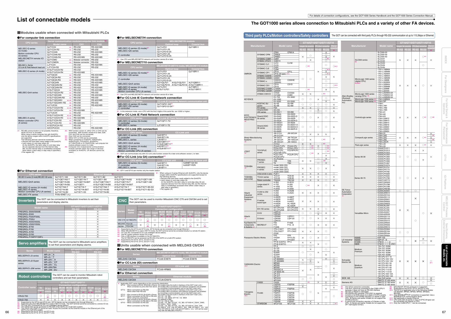
CPM1 CPM1ACPM2ACPM2CCQM1CQM1HCJ1H CJ1MCJ1GCJ2HCJ2MCP1H CP1LCP1E (N type)C200HSC200HC200HX C200HEC200HGCS1H CS1DCS1GC1000HC2000HCV500 CV2000CV1000 CVM1KV-700 KV-3000KV-1000KV-5000 KV-5500SU-5E SU-5MSU-6B SU-6MPZ3D2-240D2-250-1 D2-260D0-05AA D0-05DDD0-05AD D0-05DD-DD0-05AR D0-05DRD0-05DA D0-05DR-DD0-06DD1 D0-06AAD0-06DD2 D0-06DD1-DD0-06DR D0-06DD2-DD0-06DA D0-06DR-DD0-06ARJW-21CU JW-50CUHJW-31CUHJW-22CU JW-70CUHJW-32CUH JW-100CUHJW-33CUH JW-100CUZ-512JPC3JG-P-CPU PC3JG-CPUPC3J-CPU PC3JL-CPUPC2JC-CPU PC2J16PR-CPUPC2J16P-CPUPC2J-CPU PC2JR-CPUPC2JS-CPUT2 (PU224)T2E T2NT3 T3Hmodel 3000 (S3)model 2000 (S2)model 2000 (S2T)model 2000 (S2E)PU811TC3-01 TC6-00TC3-02 TC8-00TS2000 TS2100H-302 H-4010H-702 H-300H-1002 H-700H-2002 H-2000H-200 H-252BH-250 H-252CH-252H-20DR H-28DTH-28DR H-40DTH-40DR H-64DTH-64DR HL-40DRH-20DT HL-64DREH-CPU104 EH-CPU308EH-CPU208 EH-CPU316LQP510LQP520LQP800 LQP011LQP000 LQP120LQP010F55 F140SF70 F15MSF120SFP0-C16CT FP1-C24CFP0-C32CT FP1-C40CFP0RFP2 FP5FP2SH FP10 (S)FP3 FP10SHFP-M (C20TC) FP-ΣFP-M (C32TC)FP-XGL120GL130GL60SGL60HGL70HCP-9200SHCP-9300MSMP920MP930MP940PROGIC-8CP-9200 (H)CP-312CP-317MP2200MP2300FA500F3SP05 F3SP08F3SP10F3SP20 F3SP30F3FP36F3SP21 F3SP38F3SP25 F3SP53F3SP35 F3SP58F3SP28 F3SP59F3SP66 F3SP67NFCP100 NFJT100
SLC500-20SLC500-30SLC500-40SLC5/01SLC5/02SLC5/03SLC5/04SLC5/051761-L10BWA1761-L10BWB1761-L16AWA1761-L16BWA1761-L16BWB1761-L16BBB1761-L32AWA1761-L32BWA1761-L32BWB1761-L32BBB1761-L32AAA1761-L20AWA-5A1761-L20BWA-5A1761-L20BWB-5A1762-L24BWA1764-LSP1756-L1756-L1M11756-L1M21756-L1M31756-L611756-L621756-L631756-L55M121756-L55M131756-L55M141756-L55M161756-L55M221756-L55M231756-L55M241769-L311769-L32E1769-L32C1769-L35E1769-L35CR1794-L331794-L34IC693CPU311IC693CPU313IC693CPU323IC693CPU350IC693CPU360IC693CPU363IC693CPU366IC693CPU367IC693CPU374IC697CPU731IC697CPX772IC697CPX782IC697CPX928IC697CPX935IC697CPU780IC697CGR772IC697CGR935IC697CPU788IC697CPU789IC697CPM790IC200UAA003IC200UAR014IC200UDD104IC200UDD112IC200UDR001IC200UDR002IC200UDR003IC200UAL004IC200UAL005IC200UAL006IC200UAA007IC200UAR028IC200UDD110IC200UDD120IC200UDD212IC200UDR005IC200UDR006IC200UDR010IC200UDD064IC200UDD164IC200UDR164IC200UDR064K4P-15SK3P-07MSK7M-DMMMUK7M-DMMMS (/DC)TSX P57 203MTSX P57 253MTSX P57 303MTSX P57 353MTSX P57 453M140 CPU 311 10140 CPU 434 12U140 CPU 534 14U140 CPU 651 50140 CPU 651 60140 CPU 671 60140 CPU 113 02140 CPU 113 03140 CPU 434 12A140 CPU 534 14AFlexi Soft seriesSIMATIC S7-200 seriesSIMATIC S7-300 seriesSIMATIC S7-400 series
12
12
4 44 4
4
3
3
4
1
1 8
OMRON
KEYENCE
KOYOELECTRONICSINDUSTRIES
Sharp Manufacturing Systems
JTEKT
TOSHIBA
TOSHIBA MACHINE
HitachiIndustrialEquipmentSystems
Hitachi
Fuji Electric FAComponents& Systems
Panasonic Electric Works
YASKAWA Electric
YokogawaElectric
SYSMAC CPM
SYSMAC CQM1SYSMAC CPQ1H
SYSMAC CJ1
SYSMAC CJ2
SYSMAC CP1
SYSMAC C200HSSYSMAC C200H
SYSMAC α
SYSMAC CS1
SYSYMAC C1000HSYSYMAC C2000H
SYSMAC CVM1/CV
KOSTAC SUseriesPZ seriesDirectLOGIC205 series
DirectLOGIC05 series
DirectLOGIC06 series
TOYOPUCseries
PROSECT series
PROSECV series
Unified controller nv series
TCmini series
Robot controller
Large-sized H series
H-200 to 252 series
H series board type
EH-150 series
S10V
S10mini
MICREX-F
FA500
FA-M3
STARDOM
GE FanucAutomationCorporation
LS Industrial Systems
SchneiderElectric SA
SICK AG
Siemens AG
Series 90-30
Series 90-70
VersaMax Micro
K300SK200SK120SK80S
ModiconPremium
ModiconQuantum
1
1
10
10
1
5
567
55
5
1
1
1
1
1
1
8
81
3
3
3
14
2
1313
Model nameManufacturer Computer link connection
GT16/GT15/GT12/GT11/GT10
RS-422 RS-232 RS-422 RS-232
CPU direct connection Ethernetconnection
Computer link connection
GT16/GT15/GT12/GT11/GT10
RS-422 RS-232 RS-422 RS-232
CPU direct connection Ethernetconnection
Model nameManufacturer
Third party PLCs/Motion controllers/Safety controllers The GOT can be connected with third party PLCs through RS-232 communication at up to 115.2kbps or Ethernet.
9 9
Allen-Bradley(RockwellAutomation,Inc)
SLC500 series
MicroLogix 1000 series (digital CPU)
MicroLogix 1000 series (analog CPU)
MicroLogix 1200 seriesMicroLogix 1500 series
ControlLogix series
CompactLogix series
FlexLogix series
3
3
3
11
Modules usable when connected with Mitsubishi PLCs
MELSEC-Q series (Q mode)MELSEC-QS seriesC controller
QJ71LP21QJ71LP21-25QJ71LP21S-25QJ71LP21-25QJ71LP21S-25AJ71QLP21AJ71QLP21SAJ71LP21A1SJ71LP21
QJ71GP21-SX1
QJ71GP21S-SX1
A1SJ71QLP21A1SJ71QLP21S
QJ71BR11
AJ71QBR11A1SJ71QBR11AJ71BR11A1SJ71BR11
MELSEC-Q series (Q mode)1
MELSEC-QS series
MELSEC-Q series (Q mode)1
MELSEC-QS series
MELSEC-QnA series
MELSEC-Q series (A mode)MELSEC-A seriesMotion controller CPU (A series)
QJ71LP21QJ71LP21-25QJ71LP21S-25QJ71LP21-25QJ71LP21S-25
QJ71BR11
C controller
C controller
CPU seriesOptical loop Coaxial bus
MELSECNET/H module
CPU seriesOptical loop Coaxial bus
MELSECNET/H (NET/10 mode), MELSECNET/10 module
MELSEC-Q series (Q mode)/MELSEC-QS series
MELSEC-QnA series
MELSEC-FX series
MELSEC-Q series (A mode)MELSEC-A seriesMotion controller CPU (A series)
QJ71E71-100 QJ71E71-B5 QJ71E71-B2 QJ71E71AJ71QE71N3-TAJ71QE71N-B5AJ71QE71N-B2
AJ71QE71N-TAJ71QE71N-B5TAJ71QE71
AJ71QE71-B5A1SJ71QE71N3-TA1SJ71QE71N-B5
AJ71E71N3-TAJ71E71N-B5AJ71E71N-B2
AJ71E71N-TAJ71E71N-B5TAJ71E71-S3
A1SJ71E71N3-TA1SJ71E71N-B5A1SJ71E71N-B2
A1SJ71E71N-TA1SJ71E71N-B5T
A1SJ71E71-B5-S3A1SJ71E71-B2-S3
A1SJ71QE71N-B2A1SJ71QE71N-TA1SJ71QE71N-B5T
A1SJ71QE71-B5A1SJ71QE71-B2
CPU series Ethernet module1
MELSEC-Q series (Q mode)C controllerMELSEC-L series
MELSEC-QnA series
MELSEC-Q series (A mode)MELSEC-A seriesMotion controller CPU (A series)
QJ61BT11QJ61BT11NLJ61BT11AJ61QBT111
A1SJ61QBT111
AJ61BT111
A1SJ61BT111
CPU series CC-Link unit
CPU series CC-Link IE Controller Network communication unit
MELSEC-Q series (Q mode)C controllerMELSEC-L series
QJ61BT11QJ61BT11NLJ61BT11
AJ65BT-G4-S3AJ65BT-R2N
For computer link connection
For MELSECNET/10 connection
For MELSECNET/H connection
For Ethernet connection
For CC-Link (ID) connection
For CC-Link IE Controller Network connection
MELSEC-Q series (Q-mode)C controllerMELSEC-L series
QJ71GF11-T2
LJ71GF11-T2
CPU series CC-Link IE Field Network communication unit
For CC-Link IE Field Network connection
For CC-Link (via G4) connection1
CPU series CC-Link unit Peripheral device unit
MELSEC-Q series(Q mode)Motion controller CPU(Q series)MELSECNET/H remote I/Ostation
MELSEC-Q series (A mode)
MELSEC-QnA series
MELSEC-A seriesMotion controller CPU(A series)
MELSEC-L SeriesCC-Link IE Field Network head unit
QJ71C24QJ71C24-R2QJ71C24NQJ71C24N-R2QJ71C24N-R4QJ71CMOQJ71CMONLJ71C24LJ71C24-R2A1SJ71UC24-R2A1SJ71UC24-R4AJ71QC24AJ71QC24-R2AJ71QC24-R4AJ71QC24NAJ71QC24N-R2AJ71QC24N-R4A1SJ71QC24A1SJ71QC24-R2A1SJ71QC24NA1SJ71QC24N-R2A1SJ71QC24N1A1SJ71QC24N1-R2AJ71UC24A1SJ71UC24-R2A1SJ71UC24-R4AJ71UC24A1SJ71UC24-R2A1SJ71UC24-R4A1SJ71C24-R2A1SJ71C24-R4A1SCPUC24-R2A2CCPUC24
RS-232RS-232RS-232RS-232RS-422/485Modular connectorModular connectorRS-232RS-232RS-232RS-422/485RS-232RS-232RS-422RS-232RS-232RS-422RS-232RS-232RS-232RS-232RS-232RS-232RS-232RS-232RS-422/485RS-232RS-232RS-422/485RS-232RS-422/485RS-232RS-232
RS-422/485RS-232RS-422/485RS-232RS-422/485RS-232RS-232RS-422/485RS-232––RS-422/485RS-232RS-422/485RS-422/485RS-232RS-422/485RS-422/485RS-232RS-422/485RS-232RS-422/485RS-232RS-422/485––RS-422/485–––––RS-422/485
CPU seriesModel name CH1 CH2
Serial communication module/computer link module1
2
2
3
3
4
4
4
4
4
4
4
4
4
4
4 6
6
6
4 5
5
5
5 6
5 6
5
4
Units usable when connected with MELDAS C6/C64
MR-J3-MAMR-J3-MTMR-J2S-MAMR-J2S-MCPMR-J2S-MCLMR-J2M-P8AMR-J2MMDU
Model name GT16/GT15/GT12/GT11/GT10
GT16/GT15/GT12/GT11/GT10
RS-422 RS-232FREQROL-S500/S500EFREQROL-E500FREQROL-F500/F500LFREQROL-F500JFREQROL-A500/A500LFREQROL-V500/V500LFREQROL-E700FREQROL-F700FREQROL-A700FREQROL-D700FREQROL-F700P/F700PJ
Series Model name RS-422 RS-232
MELSERVO-J3 series
MELSERVO-J2-Super series
MELSERVO-J2M series
Series Modelname
CNC C70
MELDASC6/C64
Q173NCCPU
FCA C6FCA C64
Busconnection
CPU directconnection
Computerlink
MELSECNET/10
CC-Link(ID)
CC-Link(via G4)
Ethernet6
1 2 1 3117
CC-Link IEField Network
MELSECNET/H
4
5
4 44
MELDAS C6/C64 FCU6-EX879 FCU6-EX878
SeriesOptical loop Coaxial bus
MELSECNET/H (NET/10 mode), MELSECNET/10 module
MELDAS C6/C64 FCU6-HR865
Series CC-Link unit
MELDAS C6/C64 FCU6-EX875
For MELSECNET/10 connection
For CC-Link (ID) connection
For Ethernet connectionSeries Ethernet module
The GOT can be connected to Mitsubishi servo amplifiers to set their parameters and display alarms.
Robot controllers The GOT can be used to monitor Mitsubishi robot controllers and set their parameters.
CNC The GOT can be used to monitor Mitsubishi CNC C70 and C6/C64 and to set their parameters.
Controller name
GT16/GT15/GT12/GT11Connection configuration
Busconnection
CPU directconnection
Computerlink
MELSECNET/10
CC-Link(ID)
CC-Link(via G4)
Ethernet6
1 2 1 31 117
CC-Link IEControllerNetwork
CC-Link IEField Network
MELSECNET/H
GT16/GT15/GT12/GT11Connection configuration
CRnQ-700
CRnD-700
CC-Link IEControllerNetwork
1
4
Inverters The GOT can be connected to Mitsubishi inverters to set their parameters and display alarms.
: Applicable GOT varies depending on the connection destination.GT16 ... When connected via RS-232, RS-422/485 or Ethernet : All models (Use the built-in interface of the GOT main unit.) When connected via ports other than above : All models (Bus connection and network connection are enabled
by mounting a communication unit on the GOT main unit.)GT15 ... When connected via RS-232 : All models (Use the built-in interface of the GOT main unit.) When other than RS-232 : All models (Bus connection and network connection are enabled
by mounting a communication unit on the GOT main unit.)GT12 ... When connected via RS-232, RS-422/485 or Ethernet : All models (Use the built-in interface of the GOT main unit.)GT11 ... When connected via RS-232 or RS-422 : GT115M-QMBD When using bus connection : GT115M-QMBDQ, GT115M-QMBDA
Handy GOT ... When connected via RS-232, RS-422/485 or Ethernet : GT1665HS-VTBD When connected via RS-232 or RS-422 : GT115MHS-QMBDGT10 ... When connected via RS-232 : GT105M-QMBD, GT104M-QMBD, GT1030-HMD2/HMDW2,
GT1020-LMD2/LMDW2 When connected via RS-422 : GT105M-QMBD, GT104M-QMBD, GT1030-HMD/HMDW,
GT1030-HML/HMLW, GT1020-LMD/LMDW, GT1020-LML/LMLW(The GT1030-HML/HMLW and GT1020-LML/LMLW can be used only with the MELSEC-FXCPU.)
1 : RS-485 communication is not possible; therefore, A0J2-C214-S1 is unusable.When using A series computer link with QnACPU, only the device ranges within AnACPU specifications are supported.The following devices cannot be monitored:• Devices that have been newly added to the QnACPU• Latch relays (L) and step relays (S)
(In the QnACPU, the latch relay (L) and step relay (S) are separate devices from the internal relay (M), but the internal relay is nonetheless accessed when either a latch relay or step relay is specified.)
• File register (R)
2 :
3 :4 :5 :
6 :
With function version A, either CH1 or CH2 can be connected. With function version B or later, both CH1 and CH2 can be connected.Only CH2 can be connected.Either CH1 or CH2 can be connected.When connecting to A1SHCPU, A2SCPU(S1), A2SHCPU(S1), A1SJHCPU, A0J2HCPU, A171SHCPU(N) or A172SHCPU(N), use computer link module software version U or later.Computer link module/serial communication module operate within the range of devices available on AnACPU. (R devices cannot be used.)
1 : Use CPU and MELSECNET/H network unit function version B or later.
1 : Use CPU and MELSECNET/H network unit function version B or later.
1 : In the extension mode, use a CPU with the first 5 digits of the serial No. are 12052 or higher.
1 : GOT can communicate only with CC-Link units function version B or later and software version J or later.
1 : GT11 and GT10 can monitor only the master station.
1 : When using an A series Ethernet with QnACPU, only the device ranges within AnACPU specifications are supported except for the following devices.• Devices that have been newly added to the QnACPU• Latch relays (L) and step relays (S)
(In the QnACPU, the latch relay (L) and step relay (S) are separate devices from the internal relay (M), but the internal relay is nonetheless accessed when either a latch relay or step relay is specified.)
• File register (R)
1 :2 :3 :4 :5 :
6 :7 :
Supported by the GT16 and GT15 only. (GT16 Handy can be connected only through Ethernet.)Supported only when MELSECNET/H is used in NET/10 mode. The GOT terminal cannot be connected to a remote I/O net.CC-Link (ID): Connected as CC-Link (intelligent device station).The CRnQ-700 can be accessed via RS-232 of the QCPU of a multi-CPU system.The CRnQ-700's DISP I/F cannot be used. Access the controller via the Ethernet module or the Ethernet port of theQCPU of a multi-CPU system.Supported by the GT16, GT15, and GT12 only.Supported by the GT16, GT15, and GT11 only.
1 :2 :3 :4 :5 :
6 :7 :
Supported by the GT16 and GT15 only. (GT16 Handy can be connected only through Ethernet.)When MELSECNET/H is used in NET/10 mode, the GOT terminal cannot be connected directly to a remote I/O station.CC-Link (ID): Connected as CC-Link (intelligent device station).Use NC system software version D0 or later.Only a USB interface is available on the Q173NCCPU.The Q173NCCPU can be accessed via RS-232 of the QCPU of a multi-CPU system.Supported by the GT16, GT15, and GT12 only.Supported by the GT16, GT15, and GT11 only.
The GOT1000 series allows connection to Mitsubishi PLCs and a variety of other FA devices.
For details of connection configurations, see the GOT1000 Series Handbook and the GOT1000 Series Connection Manual.
List of connectable models
FX3U-ENET (-L)
Servo amplifiers
5
11
1 : The GT10 cannot be connected.2 : The GOT cannot be connected to the CQM1-CPU11
because it does not have an RS-232 interface.3 : RS-422 or RS232 is selectable.4 : RS-232/RS-422 converter (TXU-2051) is required.5 : Connection to the DH485 network via an adapter (1770-KF3) is possible.6 : Connection to the DH485 requires a C-Series or later
CPU. (B-Series and earlier models do not support the DH485 protocol.)
7 : A one-to-one connection requires a D-Series or later CPU. (C-Series and earlier models do not support the DF1 half-duplex format.)
8 : EtherNet/IP (PCCC protocol) is supported.9 : Supported by the GT16, GT15, and GT12 only.10 : The GT10 is applicable only to the following models: CP-9200SH, MP920, MP930, MP940, MP2200,
MP2300.11 : Only MODBUS®/TCP connection is supported. Use a
MODBUS/TCP communication driver.12 : Not applicable to duplex Ethernet13 : CPU units with 20 points or less of CP1E (N type) can
be connected only directly to CPU.14 : Only the CJ2M-CPU1M can be connected.
66 67
Fo
r Main
tenan
ceP
erson
nel
GT
10iQ
Platfo
rmFor Initial Startup &
Operations
Fo
r Desig
ners
Specifications,External D
imensions
ME
LSE
C P
rocessC
ontrolList of C
onnectableM
odels, etc.IN
DE
X
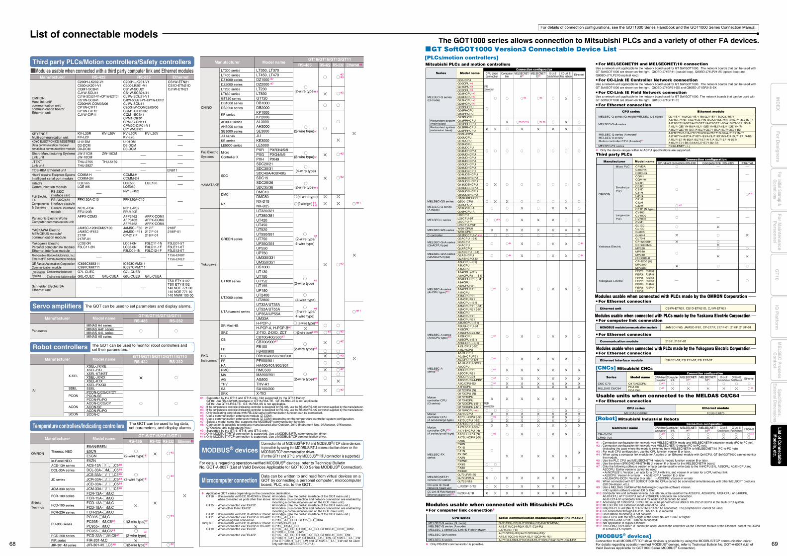
Q00JCPUQ00CPU 3
33
3
3
33
Q01CPUQ02CPUQ02HCPUQ06HCPUQ12HCPUQ25HCPUQ02PHCPUQ06PHCPUQ12PHCPUQ25PHCPUQ12PRHCPUQ25PRHCPUQ12PRHCPUQ25PRHCPUQ00UJCPUQ00UCPUQ01UCPUQ02UCPUQ03UDCPUQ04UDHCPUQ06UDHCPUQ10UDHCPUQ13UDHCPUQ20UDHCPUQ26UDHCPUQ03UDECPUQ04UDEHCPUQ06UDEHCPUQ10UDEHCPUQ13UDEHCPUQ20UDEHCPUQ26UDEHCPUQ50UDEHCPUQ100UDEHCPU
QJ72LP25-25
LJ72GF15-T2
NZ2GF-ETB
QJ72LP25GQJ72BR15
QS001CPUQ02CPU-AQ02HCPU-A
L02CPUL26CPU-BTL02CPU-PL26CPU-PBTWS0-CPU0WS0-CPU1Q12DCCPU-V 16
Q06HCPU-A
Q2ACPU (-S1)Q3ACPUQ4ACPUQ4ARCPUQ2ASCPU (-S1)Q2ASHCPUQ2ASHCPU-S1A2UCPU (-S1)A3UCPUA4UCPUA2ACPU (-S1)A2ACPUP21 (-S1)A2ACPUR21 (-S1)A3ACPUA3ACPUP21A3ACPUR21A1NCPUA1NCPUP21A1NCPUR21A2NCPU (-S1)A2NCPUP21 (-S1)A2NCPUR21 (-S1)A3NCPUA3NCPUP21A3NCPUR21A2USCPU (-S1)A2USHCPU-S1A1SCPUA1SCPUC24-R2A1SHCPUA2SCPU (-S1)A2SHCPU (-S1)A1SJCPU (-S3)A1SJHCPUA0J2HCPUA0J2HCPUP21A0J2HCPUR21A0J2HCPU-DC24A2CCPUA2CCPUP21A2CCPUR21A2CCPUC24A2CCPUC24-PRFA2CJCPU-S3A1FXCPUQ172CPU (N)Q173CPU (N)Q172HCPUQ173HCPUQ172DCPU (-S1)Q173DCPU (-S1)Q170MCPU 13
A273UCPUA273UHCPU (-S3)A373UCPU (-S3)A171SCPU (-S3)A171SCPU-S3NA171SHCPU (N)A172SHCPU (N)A173UHCPU (-S1)FX0SFX0NFX1SFX1NFX1NCFX2NFX2NCFX3GFX3UFX3UC
GT SoftGOT1000 Version3 Connectable Device List
Mitsubishi PLCs and motion controllers
CPM2AC200HXC200HGCQM1CQM1HCS1HCS1GCS1DCJ1HCJ1GCJ1MCJ2HCJ2MCP1E (N type)CV500CV1000CV2000CVM1GL120GL130GL60SGL60HGL70HCP-9200SHCP-9300MSMP920MP930MP940PROGIC-8CP-9200 (H)MP2200MP2300F3SP05 F3SP38F3SP08 F3SP53F3FP36 F3SP58F3SP21 F3SP59F3SP25 F3SP66F3SP35 F3SP67F3SP28
[PLCs/motion controllers]
CS1W-ETN21, CS1D-ETN21D, CJ1W-ETN21Ethernet unit
Modules usable when connected with PLCs made by the OMRON Corporation
8
7
7
7
7
7
7
4
4
4
4
8
CPU directconnection
Computerlink EthernetCC-Link IE
Controller NetworkCC-Link IE
Field NetworkMELSECNET/
H1MELSECNET/
102
Connection configurationModel nameSeries
MELSEC-Q series(Q mode)
Redundant system(main base)Redundant system(extension base)
MELSECNET/Hremote I/O station
CC-Link IE Field Network head unitCC-Link IE Field NetworkEthernet adaptor unit15
MELSEC-A series(AnCPU type)10
MELSEC-A series(AnSCPU type)10
MELSEC-Aseries10
MELSEC-Q series(A mode)
MELSEC-QS series
MELSEC-QnA series(QnASCPU type)
MELSEC-L series
MELSEC-WS series
C controller
MELSEC-QnA series(QnACPU type)
Motioncontroller CPU(Q series)
Motioncontroller CPU10
(A series/small type)
Motioncontroller CPU(A series/large type)
MELSEC-FXseries
USB connection
USB connection
5
5 6 12
14
5 6
5
Connection configurationEthernet
OMRON
Yaskawa Electric
Yokogawa Electric
Third party PLCs
Micro PLC
Small-size PLC
Large-size PLC
Model nameManufacturer Computer link (RS-232)CPU direct connection (RS-232)
JAMSC-IF60, JAMSC-IF61, CP-217IF, 217IF-01, 217IF, 218IF-01MEMOBUS module/communication module
Modules usable when connected with PLCs made by the Yaskawa Electric Corporation
F3LE01-5T, F3LE11-0T, F3LE12-0TEthernet interface module
Modules usable when connected with PLCs made by the Yokogawa Electric Corporation
218IF, 218IF-01Communication module
For computer link connection
For Ethernet connection
For Ethernet connection
Q173NCCPUFCA C6FCA C64
Model nameSeriesConnection configuration
CPU directconnection
MELDAS C6/C64
CNC C70
Computerlink EthernetMELSECNET/
H1MELSECNET/
102CC-Link IE
Controller NetworkCC-Link IE
Field Network
CPU directconnection
Computerlink EthernetMELSECNET/
H1MELSECNET/
102CC-Link IE
Controller NetworkCC-Link IE
Field Network
MELDAS C6/C64 FCU6-EX875
Ethernet moduleCPU series
Usable units when connected to the MELDAS C6/C64
Mitsubishi CNCs[CNCs]
Mitsubishi Industrial Robots[Robot]
[MODBUS® devices]
Controller nameConnection configuration
CRnQ-700CRnD-700
For Ethernet connection
11
11 19
9 9
18
17
The GOT1000 series allows connection to Mitsubishi PLCs and a variety of other FA devices.List of connectable models
For details of connection configurations, see the GOT1000 Series Handbook and the GOT1000 Series Connection Manual.
C200H-LK202-V1C500-LK201-V1CQM1-SCB41CJ1W-SCU41CJ1W-SCU21-V1+CP1W-EXT01CS1W-SCB41C200HW-COM03/06CP1W-CIF11CP1W-CIF12CJ1W-CIF11
C200H-LK201-V1C500-LK201-V1CS1W-SCU21CS1W-SCB21/41CJ1W-SCU21-V1CJ1W-SCU21-V1+CP1W-EXT01CJ1W-SCU41C200HW-COM02/05/06CQM1-CIF01/02CQM1-SCB41CPM1-CIF01CPM2C-CN111CPM2C-CIF01-V1CP1W-CIF01
CS1W-ETN21CS1D-ETN21DCJ1W-ETN21
RS-422Manufacturer RS-232 Ethernet Modules usable when connected with a third party computer link and Ethernet modules
KV-L20RKV-L20
KV-L20V
THU-2755THU-2927
THU-5139
KV-L20RKV-L20
KV-L20V
U-01DMD2-DCMD0-DCM
U-01DMD2-DCMD0-DCM
COMM-HCOMM-2H
JAMSC-120NOM27100JAMSC-IF612217IF217IF-01
COMM-HCOMM-2H
LQE565LQE165
AFPX-COM3
LQE560LQE060
LQE160
NV1L-RS2
FFK120A-C10 FFK120A-C10
AFP2462AFP3462AFP5462
AFPX-COM1AFPX-COM2AFPX-COM4
JAMSC-IF60JAMSC-IF61CP-217IF
217IF217IF-01218IF-01
218IF218IF-01
EN811
LC02-0NF3LC11-2N
F3LE01-5TF3LE11-0TF3LE12-0T1756-ENBT1756-ENET
TSX ETY 4102TSX ETY 5102140 NOE 771 00140 NOE 771 10140 NWM 100 00
LC01-0NLC02-0NF3LC01-1N
F3LC11-1NF3LC11-1FF3LC12-1F
IC693CMM311IC697CMM711
IC693CMM311IC697CMM711
G6L-CUEC G4L-CUEAG7L-CUEC
G6L-CUEB G4L-CUEAG7L-CUEB
JW-21CMJW-10CM
ZW-10CM
NC1L-RS4FFU120B
NC1L-RS2FFU120B
Manufacturer Model nameGT16/GT15/GT12/GT11
RS-422 RS-232 Ethernet9
LT350, LT370LT450, LT470DZ1000 7
DZ2000 7
LT230LT830GT120DB1000DB2000KP1000KP2000AL3000AH3000SE3000JUKE3000LE5000PXRPXGPXHSDC20/21SDC30/31SDC40A/40B/40GSDC15SDC25/26SDC35/36DMC10DMC50NX-D15NX-D25
PXR3/4/5/9PXG4/5/9PXH9
RS-485
(2-wire type)1
(2-wire type)1
(2-wire type)1
(4-wire type)
(2-wire type)1
(4-wire type)
(2-wire type)
UT320/321UT350/351UT420UT450UT520UT550/551UT750UP350/351UP550UP750UM330/331UM350/351US1000UT130UT150UT152UT155UP150UT2400UT2800UT32A/UT35AUT52A/UT55AUP35A/UP55AUM33AH-PCP-JH-PCP-A, H-PCP-B7
Z-TIO, Z-DIO, ZCTCB100/400/5007
CB700/9007
FB100FB400/900RB100/400/500/700/900PF900/901HA400/401/900/901RMC500MA900/901AG500THV-A1SA100/200X-TIO
(2-wire type/4-wire type)
(2-wire type)1
(4-wire type)
(2-wire type/4-wire type)
(2-wire type)1
(2-wire type)16
(2-wire type)1
(2-wire type)1
GT16/GT15/GT12/GT11/GT10RS-232
X-SEL
SSEL
PCON
ACON
SCON
XSEL-J/K/KEXSEL-P/QXSEL-KT/KETXSEL-JX/KXXSEL-KTXXSEL-PX/QXSSELPCON-C/CG/CF/CYPCON-SEPCON-PL/POACON-C/CG/CYACON-SEACON-PL/POSCON-C
RS-422
1 : Supported by the GT16 and GT15 only. Not supported by the GT16 Handy. GT16: Use RS-422/485 interface or GT15-RS4-TE. GT-15-RS4-9S is not applicable. GT15: Use GT15-RS4-TE. GT-15-RS4-9S is not applicable.2 : If the temperature controller/indicating controller is designed for RS-485, use the RS-232/RS-485 converter supplied by the manufacturer.3 : If the temperature controller/indicating controller is designed for RS-422, use the RS-232/RS-422 converter supplied by the manufacturer.4 : Only indicating controllers with RS-232 serial communication function can be connected.5 : Use a communication extension module (Z-COM).6 : Use a communication extension module (Z-COM) depending on the temperature controller system configuration.7 : Select a model name that supports the MODBUS® communication function.8 : Connection is possible to products manufactured after October, 2010 (Instrument Nos. 07Axxxxxx, 07Kxxxxxx,
07Xxxxxxx, and subsequent Nos.)9 : Supported by the GT16, GT15, and GT12 only.10 : Only MODBUS®/RTU connection is supported. Use a MODBUS/RTU communication driver.11 : Only MODBUS®/TCP connection is supported. Use a MODBUS/TCP communication driver.
Manufacturer Model name
5 2
2
2
2
2
2
23
2
2
2
OMRONHost link unit/communication unit/communication board/Ethernet unit
KEYENCEMulti-communication unit
JTEKTLink unit
Hitachi Industrial Equipment SystemsIntelligent serial port module
Panasonic Electric WorksComputer communication unit
HitachiCommunication module
TOSHIBA Ethernet unit
Fuji Electric FA Components & Systems
RS-232C interface cardRS-232C/485 interface capsuleGeneral interface module
Cnet communication unit Cnet communication module
YASKAWA ElectricMEMOBUS module/communication module
Yokogawa Electric Personal computer link module/Ethernet interface moduleAllen-Bradley (Rockwell Automation, Inc.)EtherNet/IP communication module
GE Fanuc Automation CorporationCommunication module
Schneider Electric SAEthernet unit
LS Industrial Systems
Sharp Manufacturing Systems Link unit
KOYO ELECTRONICS INDUSTRIES Data communication module/serial data communication module
Manufacturer Model nameGT16/GT15/GT12/GT11
RS-232
Panasonic
MINAS A4 seriesMINAS A4F seriesMINAS A4L seriesMINAS A5 series
RS-485
Servo amplifiers The GOT can be used to set parameters and display alarms.
Robot controllers The GOT can be used to monitor robot controllers and set their parameters.
CHINO
Fuji Electric Systems
YAMATAKE
Yokogawa
RKCInstrument
LT300 seriesLT400 seriesDZ1000 seriesDZ2000 seriesLT230 seriesLT830 seriesGT120 seriesDB1000 seriesDB2000 series
KP series
AL3000 seriesAH3000 seriesSE3000 seriesJU seriesKE seriesLE5000 series
Micro Controller X
SDC
DMC
NX
GREEN series
UT100 series
UT2000 series
UTAdvanced series
SR Mini HG
SRZ
CB
FB
RBPFHARMCMAAGTHVSASRX
: Applicable GOT varies depending on the connection destination.GT16 ... When connected via RS-232, RS-422/485 or Ethernet : All models (Use the built-in interface of the GOT main unit.) When connected via ports other than above : All models (Bus connection and network connection are enabled by
mounting a communication unit on the GOT main unit.)GT15 ... When connected via RS-232 : All models (Use the built-in interface of the GOT main unit.) When other than RS-232 : All models (Bus connection and network connection are enabled by
mounting a communication unit on the GOT main unit.)GT12 ... When connected via RS-232, RS-422/485 or Ethernet : All models (Use the built-in interface of the GOT main unit.)GT11 ... When connected via RS-232 or RS-422 : GT115M-QMBD When using bus connection : GT115M-QMBDQ, GT115M-QMBDA
Handy GOT ... When connected via RS-232, RS-422/485 or Ethernet : GT1665HS-VTBD When connected via RS-232 or RS-422 : GT115MHS-QMBDGT10 ... When connected via RS-232 : GT105M-QMBD, GT104M-QMBD, GT1030-HMD2/HMDW2, GT1020-LMD2/LMDW2 When connected via RS-422 : GT105M-QMBD, GT104M-QMBD, GT1030-HMD/HMDW, GT1030-HML/HMLW, GT1020-LMD/LMDW, GT1020-LML/LMLW
(The GT1030-HML/HMLW and GT1020-LML/LMLW can be used only with the MELSEC-FXCPU.)
1 : Connection configuration for network type MELSECNET/H mode and MELSECNET/H extension mode (PC-to-PC net).2 : Connection configuration for network type MELSECNET/10 mode (PC-to-PC net). (Including the case where the mode is switched from MELSECNET/H to MELSECNET/10 (PC-to-PC net))3 : For multi-CPU configuration, use the CPU function version B or later.4 : When using a computer link module for A series or an Ethernet module with QnACPU, GT SoftGOT1000 cannot monitor
the module.5 : Use the PLC CPU and MELSECNET/H network module function version B or later.6 : Use the driver (SW0DNC-MNETH-B) of version K or later for the MELSECNET/H board.7 : Only the following software version or later can be used to write data to the AnNCPU(S1), A2SCPU, A0J2HCPU and
A2CCPU. Earlier versions cannot be used. • AnNCPU(S1): Version L or later for a CPU with link, and version H or later for a CPU without link • A2SCPU: Version H or later • A0J2HCPU: Version E or later • A0J2HCPU-DC24: Version B or later • A2CCPU: Version H or later8 : When connected with GT SoftGOT1000, the CPUs cannot be connected simultaneously with other MELSOFT products
(GX Developer, etc.).9 : Use a MELDAS C6/C64 of the following NC system software version. • NC system software version D0 or later10 : Computer link unit software version U or later must be used for the A2SCPU, A2SHCPU, A1SHCPU, A1SJHCPU,
A0J2HCPU, A171SHCPU and A172SHCPU computer link connection. A0J2-C214-S1 (computer link unit for A0J2HCPU) cannot be used.11 : Accessing Q173NCCPU, CRnQ-700 must be performed via USB or RS-232 of QCPU in the multi-CPU system.12 : MELSECNET/H extension mode cannot be used.13 : Only the PLC unit (No.1) of Q170MCPU can be connected. The peripheral I/F cannot be used.14 : For connection through RS-232, L6ADP-R2 is required.15 : Host station monitoring is not possible.16 : Use a CPU with the first 5 digits of the serial No. are 12042 or higher.17 : Only the CJ2M-CPU1M can be connected.18 : Not applicable to duplex Ethernet19 : The CRnQ-700's DISP I/F cannot be used. Access the controller via the Ethernet module or the Ethernet port of the QCPU
of a multi-CPU system.
IAI
1
1
Third party PLCs/Motion controllers/Safety controllers
110
11
11
MODBUS® devicesConnection to all MODBUS®/RTU and MODBUS®/TCP slave devices is possible by using the MODBUS/RTU communication driver or the MODBUS/TCP communication driver.(For the GT11 and GT10, only MODBUS®/ RTU connection is supported.)
For details regarding operation-verified MODBUS® devices, refer to Technical BulletinNo. GOT-A-0037 (List of Valid Devices Applicable for GOT1000 Series MODBUS® Connection).
Microcomputer connectionData can be written to and read from virtual devices on aGOT by connecting a personal computer, microcomputerboard, PLC, etc. to the GOT.
For CC-Link IE Field Network connection
: Only RS-232 communication is possible.
MELSEC-Q series (Q mode)MELSEC-Q series (A mode)MELSEC-L series/CC-Link IE Field Network
MELSEC-QnA series
MELSEC-A series
QJ71C24(-R2)/QJ71C24N(-R2)/QJ71CMO(N)A1SJ71UC24-R2/A1SJ71C24-R2LJ71C24 (-R2)AJ71QC24(-R2)/AJ71QC24N(-R2)/A1SJ71QC24(-R2)/A1SJ71QC24N(-R2)AJ71C24-S8/AJ71UC24/A1SJ71C24-R2/A1SJ71UC24-R2
Serial communication module/computer link moduleCPU series
Modules usable when connected with Mitsubishi PLCsFor computer link connection
Use a network unit applicable to the network board used for GT SoftGOT1000. The network boards that can be used with GT SoftGOT1000 are shown on the right. Q80BD-J71BR11 (coaxial loop), Q80BD-J71LP21-25 (optical loop) and Q80BD-J71LP21G (optical loop)
Connection to all MODBUS®/TCP slave devices is possible by using the MODBUS/TCP communication driver.For details regarding operation-verified MODBUS® devices, refer to Technical Bulletin No. GOT-A-0037 (List ofValid Devices Applicable for GOT1000 Series MODBUS® Connection).
Use a network unit applicable to the network board used for GT SoftGOT1000. The network boards that can be used with GT SoftGOT1000 are shown on the right. Q80BD-J71GP21-SX and Q80BD-J71GP21S-SX
: Only the device ranges within AnACPU specifications are supported.
MELSEC-Q series (Q mode)/MELSEC-QS series
MELSEC-QnA series
QJ71E71-100/QJ71E71-B5/QJ71E71-B2/QJ71E71AJ71QE71N3-T/AJ71QE71N-B5/AJ71QE71N-B2/AJ71QE71N-T/AJ71QE71N-B5T/AJ71QE71/AJ71QE71-B5/A1SJ71QE71N3-T/A1SJ71QE71N-B5/A1SJ71QE71N-B2/A1SJ71QE71N-T/A1SJ71QE71N-B5T/A1SJ71QE71-B5/A1SJ71QE71-B2AJ71E71N3-T/AJ71E71N-B5/AJ71E71N-B2/AJ71E71N-T/AJ71E71N-B5T/AJ71E71-S3/A1SJ71E71N3-T/A1SJ71E71N-B5/A1SJ71E71N-B2/A1SJ71E71N-T/A1SJ71E71N-B5T/A1SJ71E71-B5-S3/A1SJ71E71-B2-S3FX3U-ENET (-L)MELSEC-FX series
Ethernet moduleCPU series
MELSEC-Q series (A mode)/MELSEC-A series/Motion controller CPU (A series)
For MELSECNET/H and MELSECNET/10 connection
For Ethernet connection
For CC-Link IE Controller Network connection
Manufacturer Model nameGT16/GT15/GT12/GT11
RS-422 RS-232 Ethernet9
E5AN/E5ENE5CNE5GNE5ZNACS-13A M/M,M,C58
DCL-33A-M/M,M,C58
JCS-33A-M/MM,C58
JCR-33A-M/MM,C58
JCD-33A-M/MM,C58
JCM-33A-M/M,MC58
FCR-13A-M/M,CFCR-15A-M/M,CFCD-13A-M/M,CFCD-15A-M/M,CFCR-23A-M/M,CPC935-M/M,CPC935-M/M,C58
PC955-M/M,CPC955-M/M,C58
PCD-33A-M/M,C58
FIR-201-M,CJIR-301-MM,C58
RS-485
(2-wire type)1
(2-wire type)1
(2-wire type)1
(2-wire type)
(2-wire type)1
Temperature controllers/Indicating controllers The GOT can be used to log data, set parameters, and display alarms.
2
4
2
2OMRON
ShinkoTechnos
Thermac NEO
In-Panel NEOACS-13A seriesDCL-33A series
JC series
JCM-33A series
FCR-100 series
FCD-100 series
FCR-23A series
PC-900 series
PCD-300 seriesFIR seriesJIR-301-M series
1
Use a network unit applicable to the network board used for GT SoftGOT1000. The network boards that can be used withGT SoftGOT1000 are shown on the right. Q81BD-J71GF11-T2
For Ethernet connection
68 69
Fo
r Main
tenan
ceP
erson
nel
GT
10iQ
Platfo
rmFor Initial Startup &
Operations
Fo
r Desig
ners
Specifications,External D
imensions
ME
LSE
C P
rocessC
ontrolList of C
onnectableM
odels, etc.IN
DE
X
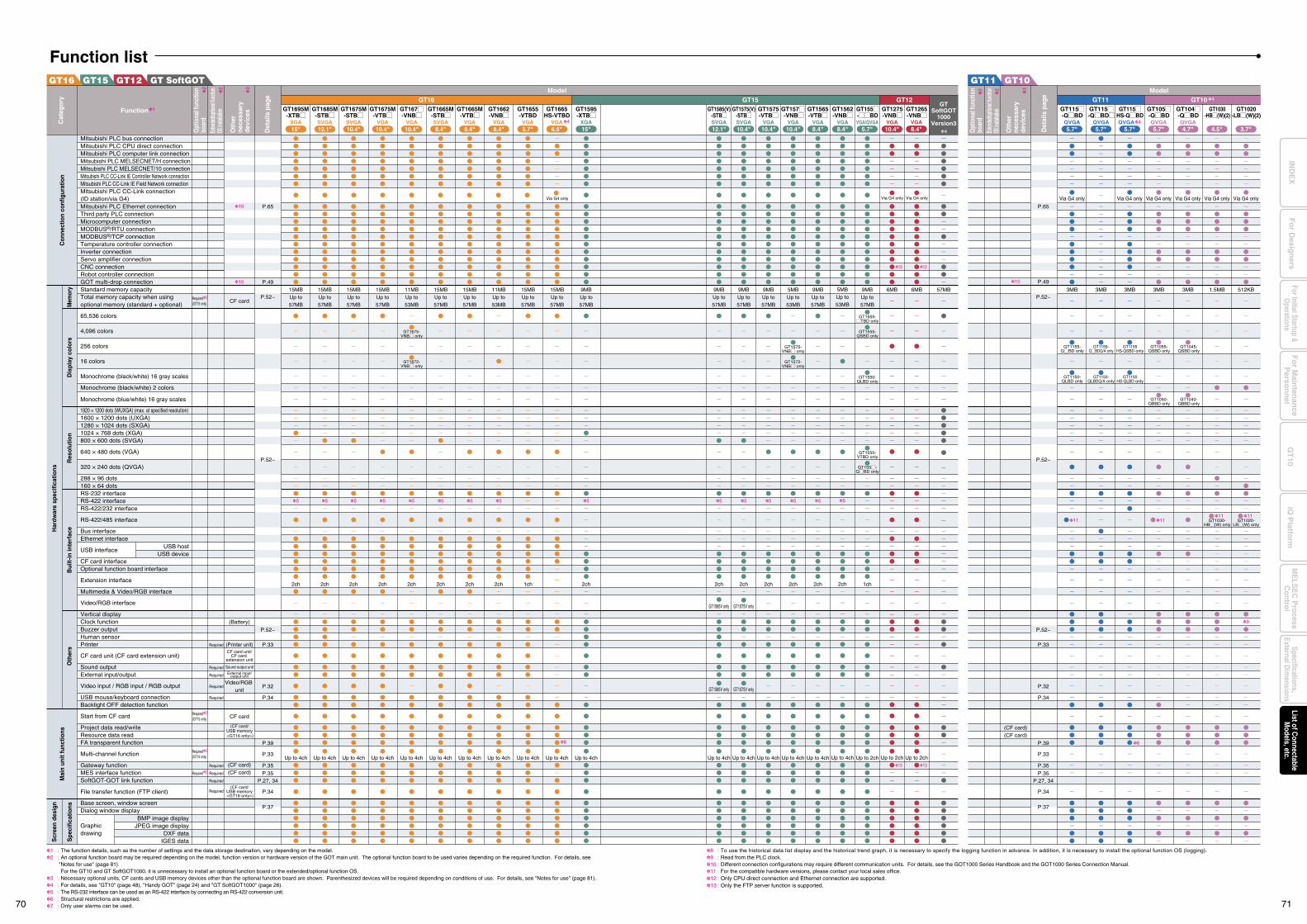
GT SoftGOTGT12
Function listGT10GT11GT15GT16
Mitsubishi PLC bus connectionMitsubishi PLC CPU direct connectionMitsubishi PLC computer link connectionMitsubishi PLC MELSECNET/H connectionMitsubishi PLC MELSECNET/10 connectionMitsubishi PLC CC-Link IE Controller Network connectionMitsubishi PLC CC-Link IE Field Network connectionMitsubishi PLC CC-Link connection (ID station/via G4)Mitsubishi PLC Ethernet connectionThird party PLC connectionMicrocomputer connectionMODBUS®/RTU connectionMODBUS®/TCP connectionTemperature controller connectionInverter connectionServo amplifier connectionCNC connectionRobot controller connectionGOT multi-drop connectionStandard memory capacityTotal memory capacity when using optional memory (standard + optional)
65,536 colors
4,096 colors
256 colors
16 colors
Monochrome (black/white) 16 gray scales
Monochrome (black/white) 2 colors
Monochrome (blue/white) 16 gray scales
1920 × 1200 dots (WUXGA) (max. at specified resolution)1600 × 1200 dots (UXGA)1280 × 1024 dots (SXGA)1024 × 768 dots (XGA)800 × 600 dots (SVGA)
640 × 480 dots (VGA)
320 × 240 dots (QVGA)
288 × 96 dots160 × 64 dotsRS-232 interfaceRS-422 interfaceRS-422/232 interface
RS-422/485 interface
Bus interfaceEthernet interface
USB interface
CF card interfaceOptional function board interface
Extension interface
Multimedia & Video/RGB interface
Video/RGB interface
Vertical displayClock functionBuzzer outputHuman sensorPrinter
CF card unit (CF card extension unit)
Sound outputExternal input/output
Video input / RGB input / RGB output
USB mouse/keyboard connectionBacklight OFF detection function
Start from CF card
Project data read/writeResource data readFA transparent function
Multi-channel function
Gateway functionMES interface functionSoftGOT-GOT link function
File transfer function (FTP client)
Base screen, window screenDialog window display
Graphicdrawing
Required2 (GT15 only)
Required2 (GT15 only)
Required2 (GT15 only)
Required2
Required
Required
Required
Required
Required
Required
Required
Required
Required
10
10
CF card
(Battery)
(Printer unit)CF card unit/
CF card extension unit
Sound output unitExternal input/
output unit
Video/RGB unit
CF card
(CF card/USB memory <GT16 only>)
(CF card)(CF card)
(CF card/USB memory <GT16 only>)
P.65
P.52~
P.49
P.52~
P.52~
P.33
P.32
P.34
P.39
P.33
P.35
P.35
P.37
P.27, 34
P.34
P.65
P.52~
P.49
P.52~
P.52~
P.33
P.32
P.34
P.39
P.33
P.35
P.35
P.37
P.34
P.27, 34
GT15 GT12GT16GT1585(V)
-STBMGT1565-VTBM
12.1" 8.4"SVGA
GT1595-XTBM
15"XGA
GT1685M-STBM
12.1"SVGA
GT1675M-STBM
10.4"SVGA
GT1675M-VTBM
10.4"VGA
GT167M-VNBM
10.4"VGA
GT1665M-STBM
8.4"SVGA
GT1665M-VTBM
8.4"VGA
GT1662-VNBM
8.4"VGA
GT1655-VTBD
5.7"VGA
GT1695M-XTBM
15"XGA
GT1575(V)-STBM
GT1575-VTBM
10.4" 10.4"SVGA VGA
GT157M-VNBM
10.4"VGA VGA
GT1562-VNBM
8.4"VGA
GT155M-MMBD
5.7"VGA/QVGA
GT1275-VNBM
10.4"VGA
GT1265-VNBM
8.4"VGA
GT115M-QMBD
5.7"QVGA
4
GTSoftGOT
1000Version3
(CF card)(CF card)
10
GT115M-QMBDM
5.7"QVGA
GT105M-QMBD
5.7"QVGA
GT1030-HBM(W)(2)
4.5"
GT1020-LBM(W)(2)
3.7"
GT115MHS-QMBD
5.7"QVGA
GT104M-QMBD
4.7"QVGA4
1 : The function details, such as the number of settings and the data storage destination, vary depending on the model.2 : An optional function board may be required depending on the model, function version or hardware version of the GOT main unit. The optional function board to be used varies depending on the required function. For details, see
"Notes for use" (page 81). For the GT10 and GT SoftGOT1000, it is unnecessary to install an optional function board or the extended/optional function OS.3 : Necessary optional units, CF cards and USB memory devices other than the optional function board are shown. Parenthesized devices will be required depending on conditions of use. For details, see "Notes for use" (page 81).4 : For details, see "GT10" (page 48), "Handy GOT" (page 24) and "GT SoftGOT1000" (page 26).5 : The RS-232 interface can be used as an RS-422 interface by connecting an RS-422 conversion unit.6 : Structural restrictions are applied.7 : Only user alarms can be used.
USB hostUSB device
BMP image displayJPEG image display
DXF dataIGES data
Model
Function
Det
ails
pag
e
Oth
er
nece
ssar
y de
vice
s
Opt
iona
l fun
ctio
n bo
ard
Exten
ded/o
ption
al fun
ction
OS in
stallat
ion1
2
3
2
Cat
egor
y
Model
Det
ails
pag
e
Oth
er
nece
ssar
y de
vice
s
Opt
iona
l fun
ctio
n bo
ard
Exten
ded/o
ption
al fun
ction
OS
insta
llation
2
3
2
GT11 GT10 4
Mem
ory
Dis
play
col
ors
Res
olut
ion
Bui
lt-in
inte
rfac
eO
ther
sS
peci
ficat
ions
Mai
n un
it fu
nctio
nsH
ardw
are
spec
ifica
tions
Scr
een
desi
gnC
onne
ctio
n co
nfig
urat
ion
9MBUp to57MB
5
2ch
Up to 4ch
9MBUp to57MB
5
2ch
Up to 4ch
5MBUp to53MB
5
2ch
Up to 4ch
9MBUp to57MB
5
2ch
GT1585V only
GT1585V only
Up to 4ch
15MBUp to57MB
5
2ch
Up to 4ch
15MBUp to57MB
5
2ch
Up to 4ch
9MBUp to57MB
1ch
Up to 2ch
57MB15MBUp to57MB
5
2ch
Up to 4ch
15MBUp to57MB
5
2ch
Up to 4ch
11MBUp to53MB
5
2ch
Up to 4ch
15MBUp to57MB
5
2ch
Up to 4ch
15MBUp to57MB
5
2ch
Up to 4ch
11MBUp to53MB
5
2ch
Up to 4ch
GT1665HS-VTBD
6.5"VGA 4
6
15MBUp to57MB
Up to 4ch
15MBUp to57MB
1ch
Up to 4ch
9MBUp to57MB
5
2ch
GT1575V only
GT1575V only
Up to 4ch
9MBUp to57MB
5
2ch
Up to 4ch
5MBUp to53MB
5
2ch
Up to 4ch
Via G4 only
3MB
11
3MB
Via G4 only
3MB
8 : To use the historical data list display and the historical trend graph, it is necessary to specify the logging function in advance. In addition, it is necessary to install the optional function OS (logging).9 : Read from the PLC clock.10 : Different connection configurations may require different communication units. For details, see the GOT1000 Series Handbook and the GOT1000 Series Connection Manual.11 : For the compatible hardware versions, please contact your local sales office.12 : Only CPU direct connection and Ethernet connection are supported.13 : Only the FTP server function is supported.
Via G4 only
1.5MB
11
Via G4 only
512KB
11
9
Via G4 only
3MB
11
Via G4 only
3MB
12 12
13 13
6MB 6MB
Up to 2ch Up to 2ch
GT1555-MTBD only
GT1555-QSBD only
GT1550-QLBD only
GT1555-VTBD only
GT155M-QMBD only
GT1572-VNBM only
GT1672-VNBM only
GT1675-VNBM only
GT1575-VNBM only
GT1150-QLBD only
GT1150HS-QLBD only
GT1155-QMBD only
GT1155HS-QSBD only
GT1155-QMBDQ/A only
GT1050-QBBD only
GT1055-QSBD only
GT1150-QLBDQ/A only
6
Via G4 only
GT1020-LBM(W) only
GT1030-HBM(W) only
GT1040-QBBD only
GT1045-QSBD only
Via G4 only Via G4 only
70 71
Fo
r Main
tenan
ceP
erson
nel
GT
10iQ
Platfo
rmFor Initial Startup &
Operations
Fo
r Desig
ners
Specifications,External D
imensions
ME
LSE
C P
rocessC
ontrolList of C
onnectableM
odels, etc.IN
DE
X
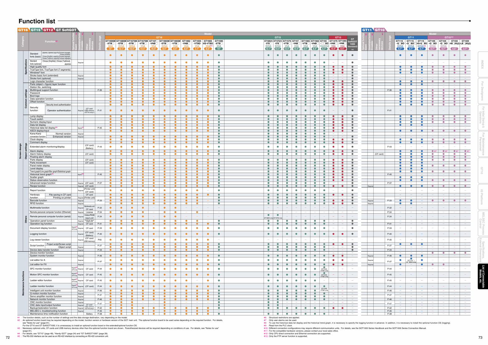
GT SoftGOTGT12GT15GT16
(Japanese, Japanese (supporting European languages), Chinese (Simplified),
Chinese (Simplified, supporting European languages), Chinese (Traditional, supporting European languages))
Chinese (Simplified), Chinese (Traditional), Japanese
Security level authentication
Operator authentication
Normal versionEnhanced version
File saving in CF cardPrinting on printer
Project script/Screen scriptObject script
P.36
P.41
P.40
P.43
P.40
P.37
P.33
P.32
P.34
P.34
P.41
P.33
P.40
P40
P.37
P.33
P.46
P.47
P.44
P.45
P.45
P.44
P.46
P.47
P.46
P.47
P.42P.46P.38
Standard fonts (basic)
Standardfonts (optional)High-quality fontTrueType font, TrueType font (7 segments)Windows® fontStroke basic font (extended)Stroke font (optional)Logo character functionParts (object + figure) layer functionStation No. switchingMultilingual support functionPasswordBoot logoData operation functionOffset function
Security function
Lamp displayTouch switchNumeric display/inputData list displayHistorical data list display8
ASCII display/inputKana-Kanji conversion functionClock displayComment display
Extended alarm monitoring/display
Alarm displayAlarm history displayFloating alarm displayParts displayParts movementPanel meter displayLevel displayTrend graph/Line graph/Bar graph/Statistical graphHistorical trend graph8
Scatter graphStatus observation functionAdvanced recipe functionRecipe function
Report function
Hardcopy functionBarcode functionRFID function
Multimedia function
Remote personal computer function (Ethernet)
Remote personal computer function (serial)
Operation panel functionOperation log function
Document display function
Logging function
Log viewer function
Script function
Device data transfer functionDevice monitor functionSystem monitor function
List editor for A
List editor for FX
SFC monitor function
Motion SFC monitor function
Ladder editor function
Ladder monitor function
Intelligent unit monitor functionQ motion monitor functionServo amplifier monitor functionNetwork monitor functionCNC monitor functionCNC data input/output functionBackup/restoration functionMELSEC-L troubleshooting functionMaintenance time notification function
Required2 (GT15 only)
Required2 (GT15 only)
Required2 (GT15 only)
Required2 (GT15 only)
Required2 (GT15 only)
Required
Required
Required
Required
Required8
Required
Required
Required8
Required
Required
Required
Required
Required
Required
Required
Required
Required
Required
Required
Required
Required
Required
Required
Required
Required
Required
Required
Required
Required
Required
Required
Required
Required
Required
Required
Required
Required
Required
Required
(CF card)
(Battery)
(CF card)
(CF card)
(CF card)
(CF card)
(CF card)
(Printer unit)
(CF card)
CF card
(Printer unit)
Multimedia unit
CF card
License
Video/RGB
input unitExternal input/
output unit
CF card
CF card
(CF card)
(Battery)
(CF card/
USB memory)
CF card
CF card
CF card
(CF card)
Battery
P.36
P.41
P.43
P.40
P.37
P.33
P.32
P.34
P.34
P.41
P.33
P.40
P.40
P.37
P.33
P.46
P.47
P.44
P.45
P.45
P.44
P.46
P.47
P.46
P.47
P.42P.46P.38
(CF card)
Required
Required
Required
Required
Required
Required
Sp
ecif
icat
ion
sC
om
mo
n s
etti
ng
sO
bje
ct s
etti
ng
sM
ain
ten
ance
fu
nct
ion
sS
cree
n d
esig
n
Oth
ers
1 : The function details, such as the number of settings and the data storage destination, vary depending on the model.2 : An optional function board may be required depending on the model, function version or hardware version of the GOT main unit. The optional function board to be used varies depending on the required function. For details,
see "Notes for use" (page 81). For the GT10 and GT SoftGOT1000, it is unnecessary to install an optional function board or the extended/optional function OS.3 : Necessary optional units, CF cards and USB memory devices other than the optional function board are shown. Parenthesized devices will be required depending on conditions of use. For details, see "Notes for use"
(page 81).4 : For details, see "GT10" (page 48), "Handy GOT" (page 24) and "GT SoftGOT1000" (page 26).5 : The RS-232 interface can be used as an RS-422 interface by connecting an RS-422 conversion unit.
6 : Structural restrictions are applied.7 : Only user alarms can be used.8 : To use the historical data list display and the historical trend graph, it is necessary to specify the logging function in advance. In addition, it is necessary to install the optional function OS (logging).9 : Read from the PLC clock.10 : Different connection configurations may require different communication units. For details, see the GOT1000 Series Handbook and the GOT1000 Series Connection Manual.11 : For the compatible hardware versions, please contact your local sales office.12 : Only CPU direct connection and Ethernet connection are supported.13 : Only the FTP server function is supported.
GT115M-QMBDA only
7 7 7 7
GT1555-VTBD only
GT1555-VTBD only
GT1555-VTBD only
GT1585V only GT1575V only
CF card/USB memory<GT16 only>
(CF card/USB memory<GT16 only>)
Function listGT10GT11
GT15GT16GT1585(V)
-STBMGT1565-VTBM
12.1" 8.4"SVGA
GT1595-XTBM
15"XGA
GT1685M-STBM
12.1"SVGA
GT1675M-STBM
10.4"SVGA
GT1675M-VTBM
10.4"VGA
GT167M-VNBM
10.4"VGA
GT1665M-STBM
8.4"SVGA
GT1665M-VTBM
8.4"VGA
GT1662-VNBM
8.4"VGA
GT1655-VTBD
GT1665HS-VTBD
5.7" 6.5"VGA VGA
GT1695M-XTBM
15"XGA
GT1575(V)-STBM
GT1575-VTBM
10.4" 10.4"SVGA VGA
GT157M-VNBM
10.4"VGA VGA
GT1562-VNBM
8.4"VGA
GT155M-MMBD
5.7"VGA/QVGA
GT115M-QMBD
5.7"QVGA
4
GTSoftGOT
1000Version3
GT115M-QMBDM
5.7"QVGA
GT105M-QMBD
5.7"QVGA
GT1030-HBM(W)(2)
4.5"
GT1020-LBM(W)(2)
3.7"
GT115MHS-QMBD
5.7"QVGA
GT104M-QMBD
4.7"QVGA44
Model
Function
Det
ails
pag
e
Oth
er
nec
essa
ry
dev
ices
Opt
iona
l fun
ctio
n bo
ard
Exten
ded/o
ption
al fun
ction
OS in
stalla
tion1
2
3
2
Cat
ego
ry
Model
Det
ails
pag
e
Oth
er
nec
essa
ry
dev
ices
Opt
iona
l fun
ctio
n bo
ard
Exten
ded/o
ption
al fun
ction
OS
insta
llatio
n
2
3
2
GT11 GT10 4GT12GT1275-VNBM
10.4"VGA
GT1265-VNBM
8.4"VGA
72 73
Fo
r Main
tenan
ceP
erson
nel
GT
10iQ
Platfo
rmFor Initial Startup &
Operations
Fo
r Desig
ners
Specifications,External D
imensions
ME
LSE
C P
rocessC
ontrolList of C
onnectableM
odels, etc.IN
DE
X
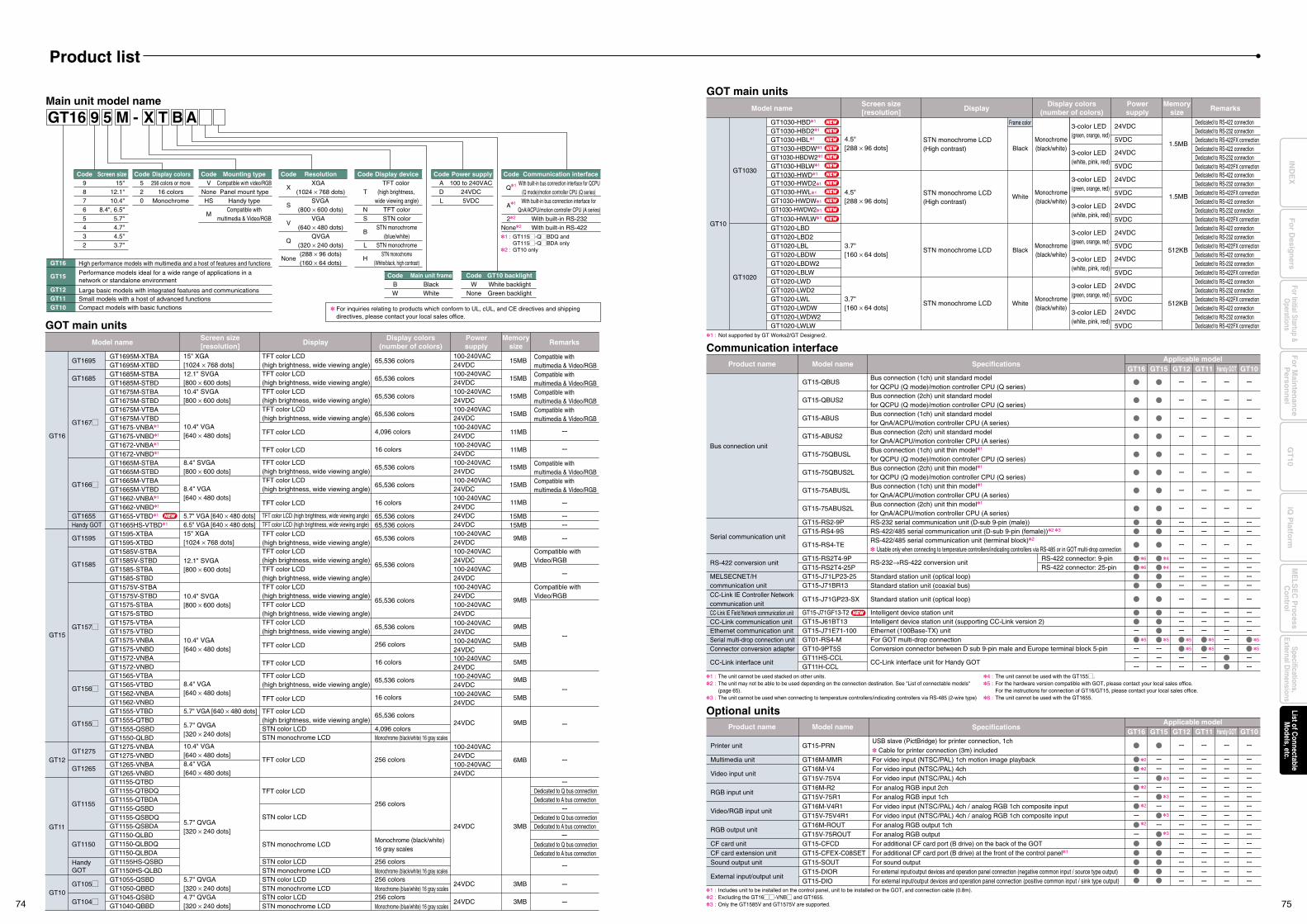
GT1555-VTBDGT1555-QTBDGT1555-QSBDGT1550-QLBD
GOT main units
STN color LCD
5.7" VGA [640 × 480 dots]
GT1155-QTBDGT1155-QTBDQGT1155-QTBDAGT1155-QSBDGT1155-QSBDQGT1155-QSBDA
GT1275-VNBAGT1275-VNBDGT1265-VNBAGT1265-VNBD
100-240VAC24VDC100-240VAC24VDC
GT1150-QLBDGT1150-QLBDQGT1150-QLBDA
GT1030-HBD1
GT1030-HBD21
GT1030-HBL1
GT1030-HBDW1
GT1030-HBDW21
GT1030-HBLW1
GT1030-HWD1
GT1030-HWD21
GT1030-HWL1
GT1030-HWDW1
GT1030-HWDW21
GT1030-HWLW1
GT1155
GT1275
GT1265
GT1150
GT1030
TFT color LCD
TFT color LCD
STN monochrome LCD
STN color LCD
STN monochrome LCDMonochrome (black/white) 16 gray scales
256 colors
256 colors
GT15
GT16
Model name Display RemarksMemory
size
GT11
GT12
GT1595
GT1585
GT157M
GT156M
GT155M
HandyGOT
GT1595-XTBAGT1595-XTBDGT1585V-STBAGT1585V-STBDGT1585-STBAGT1585-STBDGT1575V-STBAGT1575V-STBDGT1575-STBAGT1575-STBDGT1575-VTBAGT1575-VTBDGT1575-VNBAGT1575-VNBDGT1572-VNBAGT1572-VNBDGT1565-VTBAGT1565-VTBDGT1562-VNBAGT1562-VNBD
GT1155HS-QSBDGT1150HS-QLBD
15" XGA[1024 × 768 dots]
12.1" SVGA[800 × 600 dots]
10.4" SVGA[800 × 600 dots]
10.4" VGA[640 × 480 dots]
8.4" VGA[640 × 480 dots]
5.7" QVGA[320 × 240 dots]
5.7" QVGA[320 × 240 dots]
10.4" VGA[640 × 480 dots]8.4" VGA[640 × 480 dots]
4.5"[288 × 96 dots]
TFT color LCD
TFT color LCD
TFT color LCD(high brightness, wide viewing angle)
TFT color LCD(high brightness, wide viewing angle)
STN color LCDSTN monochrome LCD
STN monochrome LCD(High contrast)
Frame color
Black
White
65,536 colors
65,536 colors
Compatible withVideo/RGB
Compatible with multimedia & Video/RGB Compatible with multimedia & Video/RGB
Compatible withVideo/RGB
65,536 colors
65,536 colors
256 colors
16 colors
65,536 colors
16 colors
65,536 colors
4,096 colorsMonochrome (black/white) 16 gray scales
256 colorsMonochrome (black/white) 16 gray scales
Monochrome(black/white)
100-240VAC24VDC100-240VAC24VDC100-240VAC24VDC100-240VAC24VDC100-240VAC24VDC100-240VAC24VDC100-240VAC24VDC100-240VAC24VDC100-240VAC24VDC100-240VAC24VDC
24VDC
24VDC
9MB
GT1685GT1685M-STBAGT1685M-STBD
12.1" SVGA[800 × 600 dots]
65,536 colors100-240VAC24VDC
15MB
GT1695GT1695M-XTBAGT1695M-XTBD
15" XGA[1024 × 768 dots]
65,536 colors100-240VAC24VDC
15MB
9MB
9MB
Dedicated to Q bus connectionDedicated to A bus connection
Dedicated to Q bus connectionDedicated to A bus connection
Dedicated to Q bus connectionDedicated to A bus connection
Dedicated to RS-422 connectionDedicated to RS-232 connectionDedicated to RS-422FX connectionDedicated to RS-422 connectionDedicated to RS-232 connectionDedicated to RS-422FX connection
9MB
5MB
5MB
9MB
5MB
9MB
3MB
6MB
1.5MB
4.5"[288 × 96 dots]
STN monochrome LCD(High contrast)
Monochrome(black/white)
Dedicated to RS-422 connectionDedicated to RS-232 connectionDedicated to RS-422FX connectionDedicated to RS-422 connectionDedicated to RS-232 connectionDedicated to RS-422FX connection
1.5MB
Screen size[resolution]
Display colors(number of colors)
Powersupply
GOT main unitsModel name Display Remarks
Memorysize
Screen size[resolution]
Display colors(number of colors)
Powersupply
TFT color LCD(high brightness, wide viewing angle)TFT color LCD(high brightness, wide viewing angle)
Compatible with multimedia & Video/RGB
GT167M
GT1675M-STBAGT1675M-STBDGT1675M-VTBAGT1675M-VTBDGT1675-VNBA1
GT1675-VNBD1
GT1672-VNBA1
GT1672-VNBD1
GT1665M-STBAGT1665M-STBDGT1665M-VTBAGT1665M-VTBDGT1662-VNBA1
GT1662-VNBD1
GT1655-VTBD1
GT1665HS-VTBD1
10.4" SVGA[800 × 600 dots]
65,536 colors100-240VAC24VDC
15MBTFT color LCD(high brightness, wide viewing angle)
Compatible with multimedia & Video/RGB
10.4" VGA[640 × 480 dots]
65,536 colors100-240VAC24VDC100-240VAC24VDC100-240VAC24VDC
15MB
11MB
11MB
TFT color LCD(high brightness, wide viewing angle)
TFT color LCD
TFT color LCD
Compatible with multimedia & Video/RGB
GT166M
GT1655Handy GOT
8.4" SVGA[800 × 600 dots]
65,536 colors100-240VAC24VDC
15MB
11MB
15MB15MB
TFT color LCD(high brightness, wide viewing angle)
TFT color LCD
TFT color LCD (high brightness, wide viewing angle)TFT color LCD (high brightness, wide viewing angle)
Compatible with multimedia & Video/RGB 8.4" VGA
[640 × 480 dots]
6.5" VGA [640 × 480 dots]5.7" VGA [640 × 480 dots]
65,536 colors
4,096 colors
16 colors
16 colors
65,536 colors65,536 colors
100-240VAC24VDC100-240VAC24VDC24VDC24VDC
15MB
NEW
TFT color LCD(high brightness, wide viewing angle)
TFT color LCD(high brightness, wide viewing angle)TFT color LCD(high brightness, wide viewing angle)TFT color LCD(high brightness, wide viewing angle)TFT color LCD(high brightness, wide viewing angle)TFT color LCD(high brightness, wide viewing angle)TFT color LCD(high brightness, wide viewing angle)
TFT color LCD
GT10
Black
White
STN monochrome LCDMonochrome(black/white)
24VDC
24VDC
GT1020
GT1020-LBDGT1020-LBD2GT1020-LBLGT1020-LBDWGT1020-LBDW2GT1020-LBLW
3.7"[160 × 64 dots]
5VDC
5VDC
3-color LED(green, orange, red)
3-color LED(white, pink, red)
Dedicated to RS-422 connectionDedicated to RS-232 connectionDedicated to RS-422FX connectionDedicated to RS-422 connectionDedicated to RS-232 connectionDedicated to RS-422FX connection
512KB
STN monochrome LCDMonochrome(black/white)
24VDC
24VDC
GT1020-LWDGT1020-LWD2GT1020-LWLGT1020-LWDWGT1020-LWDW2GT1020-LWLW
3.7"[160 × 64 dots]
5VDC
5VDC
3-color LED(green, orange, red)
3-color LED(white, pink, red)
24VDC
24VDC
5VDC
5VDC
3-color LED(green, orange, red)
3-color LED(white, pink, red)
24VDC
24VDC
5VDC
5VDC
3-color LED(green, orange, red)
3-color LED(white, pink, red)
Dedicated to RS-422 connectionDedicated to RS-232 connectionDedicated to RS-422FX connectionDedicated to RS-422 connectionDedicated to RS-232 connectionDedicated to RS-422FX connection
512KB
GT10
5.7" QVGA[320 × 240 dots]
GT105MGT1055-QSBDGT1050-QBBD
STN color LCDSTN monochrome LCD
256 colorsMonochrome (blue/white) 16 gray scales
24VDC 3MB
4.7" QVGA[320 × 240 dots]
GT104MGT1045-QSBDGT1040-QBBD
STN color LCDSTN monochrome LCD
256 colorsMonochrome (blue/white) 16 gray scales
24VDC 3MB
Communication interfaceProduct name Model name Specifications
Applicable modelGT15 GT12 GT11 Handy GOT GT10
CC-Link IE Controller Network communication unitCC-Link IE Field Network communication unit
GT15-QBUS
GT15-QBUS2
GT15-ABUS
GT15-ABUS2
GT15-75QBUSL
GT15-75QBUS2L
GT15-75ABUSL
GT15-75ABUS2L
GT15-RS2-9PGT15-RS4-9S
GT15-RS4-TE
GT15-RS2T4-9PGT15-RS2T4-25P
GT15-J71E71-100GT01-RS4-MGT10-9PT5SGT11HS-CCLGT11H-CCL
GT15-J71LP23-25GT15-J71BR13
GT15-J61BT13GT15-J71GF13-T2
GT15-J71GP23-SX
3
3
3
3
Standard station unit (optical loop)
Standard station unit (optical loop)
Standard station unit (coaxial bus)
Intelligent device station unit (supporting CC-Link version 2)Ethernet (100Base-TX) unitFor GOT multi-drop connectionConversion connector between D sub 9-pin male and Europe terminal block 5-pin
CC-Link interface unit for Handy GOT
Intelligent device station unit
2
2
2
2
2
RS-422 connector: 9-pinRS-422 connector: 25-pin
4
4
6
6
55 5 5
5
5
5 5
Product name Model name SpecificationsApplicable model
GT15
GT16
GT16 GT11GT12 Handy GOT GT10
Printer unit
Multimedia unit
Video input unit
RGB input unit
Video/RGB input unit
RGB output unit
CF card unitCF card extension unitSound output unit
External input/output unit
GT15-PRN
GT16M-MMRGT16M-V4GT15V-75V4GT16M-R2GT15V-75R1GT16M-V4R1GT15V-75V4R1GT16M-ROUTGT15V-75ROUTGT15-CFCDGT15-CFEX-C08SETGT15-SOUTGT15-DIORGT15-DIO
USB slave (PictBridge) for printer connection, 1ch Cable for printer connection (3m) includedFor video input (NTSC/PAL) 1ch motion image playbackFor video input (NTSC/PAL) 4chFor video input (NTSC/PAL) 4chFor analog RGB input 2chFor analog RGB input 1chFor video input (NTSC/PAL) 4ch / analog RGB 1ch composite inputFor video input (NTSC/PAL) 4ch / analog RGB 1ch composite inputFor analog RGB output 1ch For analog RGB outputFor additional CF card port (B drive) on the back of the GOTFor additional CF card port (B drive) at the front of the control panel1
For sound outputFor external input/output devices and operation panel connection (negative common input / source type output)For external input/output devices and operation panel connection (positive common input / sink type output)
Bus connection unit
Serial communication unit
RS-422 conversion unit
MELSECNET/H communication unit
CC-Link communication unitEthernet communication unitSerial multi-drop connection unitConnector conversion adapter
CC-Link interface unit
1 :2 :
3 :
The unit cannot be used stacked on other units.The unit may not be able to be used depending on the connection destination. See "List of connectable models" (page 65).The unit cannot be used when connecting to temperature controllers/indicating controllers via RS-485 (2-wire type)
4 :5 :
6 :
The unit cannot be used with the GT155M.For the hardware version compatible with GOT, please contact your local sales office.For the instructions for connection of GT16/GT15, please contact your local sales office.The unit cannot be used with the GT1655.
Bus connection (1ch) unit standard model for QCPU (Q mode)/motion controller CPU (Q series)Bus connection (2ch) unit standard model for QCPU (Q mode)/motion controller CPU (Q series)Bus connection (1ch) unit standard model for QnA/ACPU/motion controller CPU (A series)Bus connection (2ch) unit standard model for QnA/ACPU/motion controller CPU (A series)Bus connection (1ch) unit thin model1 for QCPU (Q mode)/motion controller CPU (Q series)Bus connection (2ch) unit thin model1 for QCPU (Q mode)/motion controller CPU (Q series)Bus connection (1ch) unit thin model1 for QnA/ACPU/motion controller CPU (A series)Bus connection (2ch) unit thin model1 for QnA/ACPU/motion controller CPU (A series)RS-232 serial communication unit (D-sub 9-pin (male))RS-422/485 serial communication unit (D-sub 9-pin (female))2 3 RS-422/485 serial communication unit (terminal block)2
Usable only when connecting to temperature controllers/indicating controllers via RS-485 or in GOT multi-drop connection
RS-232→RS-422 conversion unit
1 :2 :3 :
Includes unit to be installed on the control panel, unit to be installed on the GOT, and connection cable (0.8m).Excluding the GT16MM-VNBM and GT1655.Only the GT1585V and GT1575V are supported.
Optional units
NEW
NEW
NEW
NEW
NEW
NEW
NEW
NEW
NEW
NEW
NEW
NEW
1 : Not supported by GT Works2/GT Designer2.
NEW
GT16 9 5 M - X T B AMain unit model name
For inquiries relating to products which conform to UL, cUL, and CE directives and shippingdirectives, please contact your local sales office.
Screen sizeCode98765432
15"12.1"10.4"
8.4", 6.5"5.7"4.7"4.5"3.7"
Code52
256 colors or more16 colors
Monochrome
CodeV
NoneHS
M
Compatible wirh video/RGBPanel mount type
Handy typeCompatible with
multimedia & Video/RGB
Code
X
S
V
Q
None
XGA (1024 × 768 dots)
SVGA (800 × 600 dots)
VGA (640 × 480 dots)
QVGA (320 × 240 dots)(288 × 96 dots)(160 × 64 dots)
Code
T
NS
B
L
H
TFT color (high brightness,
wide viewing angle)TFT colorSTN color
STN monochrome(blue/white)
STN monochromeSTN monochrome
(White/black, high contrast)
CodeADL
100 to 240VAC24VDC5VDC
CodeW
NoneWhite backlightGreen backlight
Main unit frameCodeBW
BlackWhite
Performance models ideal for a wide range of applications in a network or standalone environment
Large basic models with integrated features and communications
GT16
GT15
GT12GT11GT10
Small models with a host of advanced functions
High performance models with multimedia and a host of features and functions
Compact models with basic functions
Code
0
Display colors Mounting type Resolution Display device
GT10 backlight
Communication interface Power supply
1 :
2 :
GT115M-QMBDQ and GT115M-QMBDA only GT10 only
Q1
A1
22
None2
With built-in bus connection interface for QCPU(Q mode)/motion controller CPU (Q series) With built-in bus connection interface for
QnA/ACPU/motion controller CPU (A series)With built-in RS-232With built-in RS-422
Product list
74 75
Fo
r Main
tenan
ceP
erson
nel
GT
10iQ
Platfo
rmFor Initial Startup &
Operations
Fo
r Desig
ners
Specifications,External D
imensions
ME
LSE
C P
rocessC
ontrolList of C
onnectableM
odels, etc.IN
DE
X
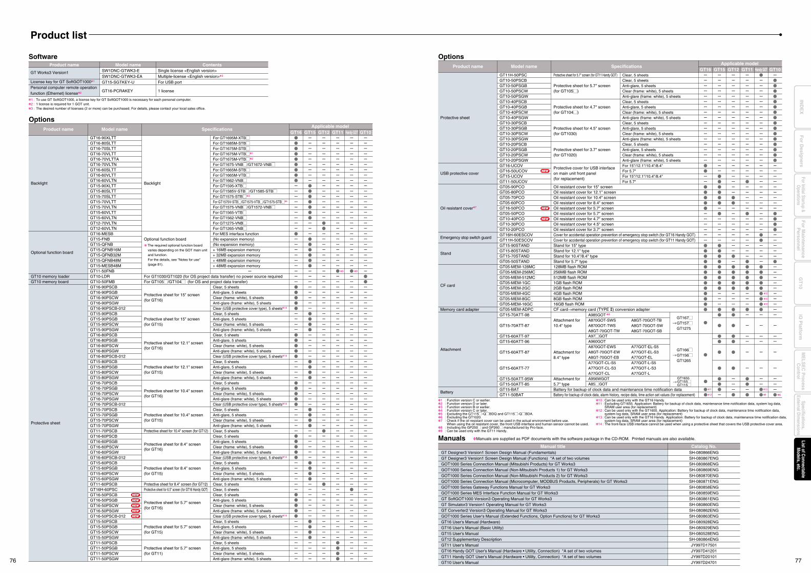
Manual title Catalog No.GT Designer3 Version1 Screen Design Manual (Fundamentals)GT Designer3 Version1 Screen Design Manual (Functions) *A set of two volumesGOT1000 Series Connection Manual (Mitsubishi Products) for GT Works3GOT1000 Series Connection Manual (Non-Mitsubishi Products 1) for GT Works3GOT1000 Series Connection Manual (Non-Mitsubishi Products 2) for GT Works3GOT1000 Series Connection Manual (Microcomputer, MODBUS Products, Peripherals) for GT Works3GOT1000 Series Gateway Functions Manual for GT Works3GOT1000 Series MES Interface Function Manual for GT Works3GT SoftGOT1000 Version3 Operating Manual for GT Works3GT Simulator3 Version1 Operating Manual for GT Works3GT Converter2 Version3 Operating Manual for GT Works3GOT1000 Series User's Manual (Extended Functions, Option Functions) for GT Works3GT16 User's Manual (Hardware)GT16 User's Manual (Basic Utility)GT15 User's ManualGT12 Supplementary DescriptionGT11 User's ManualGT16 Handy GOT User's Manual (Hardware • Utility, Connection) *A set of two volumesGT11 Handy GOT User's Manual (Hardware • Utility, Connection) *A set of two volumesGT10 User's Manual
SH-080866ENGSH-080867ENGSH-080868ENGSH-080869ENGSH-080870ENGSH-080871ENGSH-080858ENGSH-080859ENGSH-080861ENGSH-080860ENGSH-080862ENGSH-080863ENGSH-080928ENGSH-080929ENGSH-080528ENGSH-080864ENGJY997D17501JY997D41201JY997D20101JY997D24701
Manuals Manuals are supplied as PDF documents with the software package in the CD-ROM. Printed manuals are also available.
1 : Function version C or earlier.2 : Function version D or later.3 : Function version B or earlier.4 : Function version C or later.5 : Excluding the GT115M-QMBDQ and GT115M-QMBDA.6 : Excluding the GT1020.7 : Check if the oil resistant cover can be used in the actual environment before use. When using the oil resistant cover, the front USB interface and human sensor cannot be used.8 : Including the GP250M and GP260M manufactured by Pro-face.9 : Can be used only with the GT11 Handy.
10 : Can be used only with the GT16 Handy.11 : Excluding GT1655. Application: Battery for backup of clock data, maintenance time notification data, system log data, SRAM user area (for replacement)12 : Can be used only with the GT1655. Application: Battery for backup of clock data, maintenance time notification data, system log data, SRAM user area (for replacement)13 : Can be used only with the GT16 Handy. Application: Battery for backup of clock data, maintenance time notification data, system log data, SRAM user area (for replacement)14 : The front-face USB interface cannot be used when using a protective sheet that covers the USB protective cover area.
Model name SpecificationsApplicable model
GT15GT16 GT11GT12
Attachment
Battery
GT15-70ATT-98
GT15-70ATT-87
GT15-60ATT-97GT15-60ATT-96
GT15-60ATT-87
GT15-60ATT-77
GT15-50ATT-95WGT15-50ATT-85GT15-BATGT11-50BAT
Attachment for 10.4" type
Attachment for 8.4" type
Attachment for 5.7" typeBattery for backup of clock data and maintenance time notification dataBattery for backup of clock data, alarm history, recipe data, time action set values (for replacement)
Product nameHandy GOT GT10
GT1655GT155MGT115M
→
GT167MGT157MGT1275
→
GT166MGT156MGT1265
→
6
A985GOT 8
A870GOT-SWSA870GOT-TWSA8GT-70GOT-TWA97MGOTA960GOTA870GOT-EWSA8GT-70GOT-EWA8GT-70GOT-EBA77GOT-CL-S5A77GOT-CL-S3A77GOT-CLA956WGOTA85MGOT
A77GOT-L-S5A77GOT-L-S3A77GOT-L
A77GOT-EL-S5A77GOT-EL-S3A77GOT-EL
A8GT-70GOT-TBA8GT-70GOT-SWA8GT-70GOT-SB
Oil resistant cover7
Emergency stop switch guard
Stand
CF card
Memory card adapter
GT05-90PCOGT05-80PCOGT05-70PCOGT05-60PCOGT16-50PCOGT05-50PCOGT10-40PCOGT10-30PCOGT10-20PCOGT16H-60ESCOVGT11H-50ESCOVGT15-90STANDGT15-80STANDGT15-70STANDGT05-50STANDGT05-MEM-128MCGT05-MEM-256MCGT05-MEM-512MCGT05-MEM-1GCGT05-MEM-2GCGT05-MEM-4GCGT05-MEM-8GCGT05-MEM-16GCGT05-MEM-ADPC
Oil resistant cover for 15" screenOil resistant cover for 12.1" screenOil resistant cover for 10.4" screenOil resistant cover for 8.4" screenOil resistant cover for 5.7" screenOil resistant cover for 5.7" screenOil resistant cover for 4.7" screenOil resistant cover for 4.5" screenOil resistant cover for 3.7" screenCover for accidental operation prevention of emergency stop switch (for GT16 Handy GOT)Cover for accidental operation prevention of emergency stop switch (for GT11 Handy GOT)Stand for 15" typeStand for 12.1" typeStand for 10.4"/8.4" typeStand for 5.7" type128MB flash ROM256MB flash ROM512MB flash ROM1GB flash ROM2GB flash ROM4GB flash ROM8GB flash ROM16GB flash ROMCF card→memory card (TYPE @) conversion adapter
10
10
10
9
13
12
11
OptionsProduct name Model name Contents
GT Works3 Version1
License key for GT SoftGOT10001
Personal computer remote operation function (Ethernet) license2
SW1DNC-GTWK3-E SW1DNC-GTWK3-EAGT15-SGTKEY-U
GT16-PCRAKEY
Single license <English version>Multiple-license <English version>3
For USB port
1 license
Software
Product list
1 :2 :3 :
To use GT SoftGOT1000, a license key for GT SoftGOT1000 is necessary for each personal computer.1 license is required for 1 GOT unit.The desired number of licenses (2 or more) can be purchased. For details, please contact your local sales office.
Model name SpecificationsApplicable model
GT15 GT12GT16 GT11
Backlight
Optional function board
GT10 memory loader GT10 memory board
Protective sheet
GT16-90XLTTGT16-80SLTTGT16-70SLTTGT16-70VLTTGT16-70VLTTAGT16-70VLTNGT16-60SLTTGT16-60VLTTGT16-60VLTNGT15-90XLTTGT15-80SLTTGT15-70SLTTGT15-70VLTTGT15-70VLTNGT15-60VLTTGT15-60VLTNGT12-70VLTNGT12-60VLTNGT16-MESBGT15-FNBGT15-QFNBGT15-QFNB16MGT15-QFNB32MGT15-QFNB48MGT15-MESB48MGT11-50FNBGT10-LDRGT10-50FMBGT16-90PSCBGT16-90PSGBGT16-90PSCWGT16-90PSGWGT16-90PSCB-012GT15-90PSCBGT15-90PSGBGT15-90PSCWGT15-90PSGWGT16-80PSCBGT16-80PSGBGT16-80PSCWGT16-80PSGWGT16-80PSCB-012GT15-80PSCBGT15-80PSGBGT15-80PSCWGT15-80PSGWGT16-70PSCBGT16-70PSGBGT16-70PSCWGT16-70PSGWGT16-70PSCB-012GT15-70PSCBGT15-70PSGBGT15-70PSCWGT15-70PSGWGT11-70PSCBGT16-60PSCBGT16-60PSGBGT16-60PSCWGT16-60PSGWGT16-60PSCB-012GT15-60PSCBGT15-60PSGBGT15-60PSCWGT15-60PSGWGT11-60PSCBGT16H-60PSCGT16-50PSCBGT16-50PSGBGT16-50PSCWGT16-50PSGWGT16-50PSCB-012GT15-50PSCBGT15-50PSGBGT15-50PSCWGT15-50PSGWGT11-50PSCBGT11-50PSGBGT11-50PSCWGT11-50PSGW
Backlight
Optional function board
For GT1030/GT1020 (for OS project data transfer) no power source requiredFor GT105M/GT104M (for OS and project data transfer)
Protective sheet for 15" screen(for GT16)
Protective sheet for 15" screen(for GT15)
Protective sheet for 12.1" screen(for GT16)
Protective sheet for 12.1" screen(for GT15)
Protective sheet for 10.4" screen(for GT16)
Protective sheet for 10.4" screen(for GT15)
Protective sheet for 10.4" screen (for GT12)
Protective sheet for 8.4" screen(for GT16)
Protective sheet for 8.4" screen(for GT15)
Protective sheet for 8.4" screen (for GT12)Protective sheet for 6.5" screen (for GT16 Handy GOT)
Protective sheet for 5.7" screen (for GT16)
Protective sheet for 5.7" screen (for GT15)
Protective sheet for 5.7" screen (for GT11)
For GT1695M-XTBMFor GT1685M-STBMFor GT1675M-STBMFor GT1675M-VTBM1
For GT1675M-VTBM2
For GT1675-VNBM/GT1672-VNBMFor GT1665M-STBMFor GT1665M-VTBMFor GT1662-VNBMFor GT1595-XTBMFor GT1585V-STBM/GT1585-STBMFor GT1575-STBM3
For GT1575V-STBM/GT1575-VTBM/GT1575-STBM4
For GT1575-VNBM/GT1572-VNBMFor GT1565-VTBMFor GT1562-VNBMFor GT1275-VNBMFor GT1265-VNBMFor MES interface function(No expansion memory)(No expansion memory)+ 16MB expansion memory+ 32MB expansion memory+ 48MB expansion memory+ 48MB expansion memory
Clear, 5 sheetsAnti-glare, 5 sheetsClear (frame: white), 5 sheetsAnti-glare (frame: white), 5 sheetsClear (USB protective cover type), 5 sheets14
Clear, 5 sheetsAnti-glare, 5 sheetsClear (frame: white), 5 sheetsAnti-glare (frame: white), 5 sheetsClear, 5 sheetsAnti-glare, 5 sheetsClear (frame: white), 5 sheetsAnti-glare (frame: white), 5 sheetsClear (USB protective cover type), 5 sheets14
Clear, 5 sheetsAnti-glare, 5 sheetsClear (frame: white), 5 sheetsAnti-glare (frame: white), 5 sheetsClear, 5 sheetsAnti-glare, 5 sheetsClear (frame: white), 5 sheetsAnti-glare (frame: white), 5 sheetsClear (USB protective cover type), 5 sheets14
Clear, 5 sheetsAnti-glare, 5 sheetsClear (frame: white), 5 sheetsAnti-glare (frame: white), 5 sheetsClear, 5 sheetsClear, 5 sheetsAnti-glare, 5 sheetsClear (frame: white), 5 sheetsAnti-glare (frame: white), 5 sheetsClear (USB protective cover type), 5 sheets14
Clear, 5 sheetsAnti-glare, 5 sheetsClear (frame: white), 5 sheetsAnti-glare (frame: white), 5 sheetsClear, 5 sheetsClear, 5 sheetsClear, 5 sheetsAnti-glare, 5 sheetsClear (frame: white), 5 sheetsAnti-glare (frame: white), 5 sheetsClear (USB protective cover type), 5 sheets14
Clear, 5 sheetsAnti-glare, 5 sheetsClear (frame: white), 5 sheetsAnti-glare (frame: white), 5 sheetsClear, 5 sheetsAnti-glare, 5 sheetsClear (frame: white), 5 sheetsAnti-glare (frame: white), 5 sheets
Protective sheet
USB protective cover
GT10-30PSCBGT10-30PSGBGT10-30PSCWGT10-30PSGWGT10-20PSCBGT10-20PSGBGT10-20PSCWGT10-20PSGWGT16-UCOVGT16-50UCOVGT15-UCOVGT11-50UCOV
Protective sheet for 4.5" screen (for GT1030)
Protective sheet for 3.7" screen (for GT1020)
Protective cover for USB interfaceon main unit front panel(for replacement)
Clear, 5 sheetsAnti-glare, 5 sheetsClear (frame: white), 5 sheetsAnti-glare (frame: white), 5 sheetsClear, 5 sheetsAnti-glare, 5 sheetsClear (frame: white), 5 sheetsAnti-glare (frame: white), 5 sheetsFor 15"/12.1"/10.4"/8.4"For 5.7"For 15"/12.1"/10.4"/8.4"For 5.7"
GT11H-50PSCGT10-50PSCBGT10-50PSGBGT10-50PSCWGT10-50PSGWGT10-40PSCBGT10-40PSGBGT10-40PSCWGT10-40PSGW
Protective sheet for 5.7" screen (for GT11 Handy GOT)
Protective sheet for 5.7" screen (for GT105M)
Protective sheet for 4.7" screen (for GT104M)
Clear, 5 sheetsClear, 5 sheetsAnti-glare, 5 sheetsClear (frame: white), 5 sheetsAnti-glare (frame: white), 5 sheetsClear, 5 sheetsAnti-glare, 5 sheetsClear (frame: white), 5 sheetsAnti-glare (frame: white), 5 sheets
Product name
Options
Handy GOT GT10
The required optional function board varies depending on the GOT main unit and function.For the details, see "Notes for use" (page 81).
5 9
NEW
NEW
NEW
NEW
NEW
NEW
NEW
NEW
76 77
Fo
r Main
tenan
ceP
erson
nel
GT
10iQ
Platfo
rmFor Initial Startup &
Operations
Fo
r Desig
ners
Specifications,External D
imensions
ME
LSE
C P
rocessC
ontrolList of C
onnectableM
odels, etc.IN
DE
X
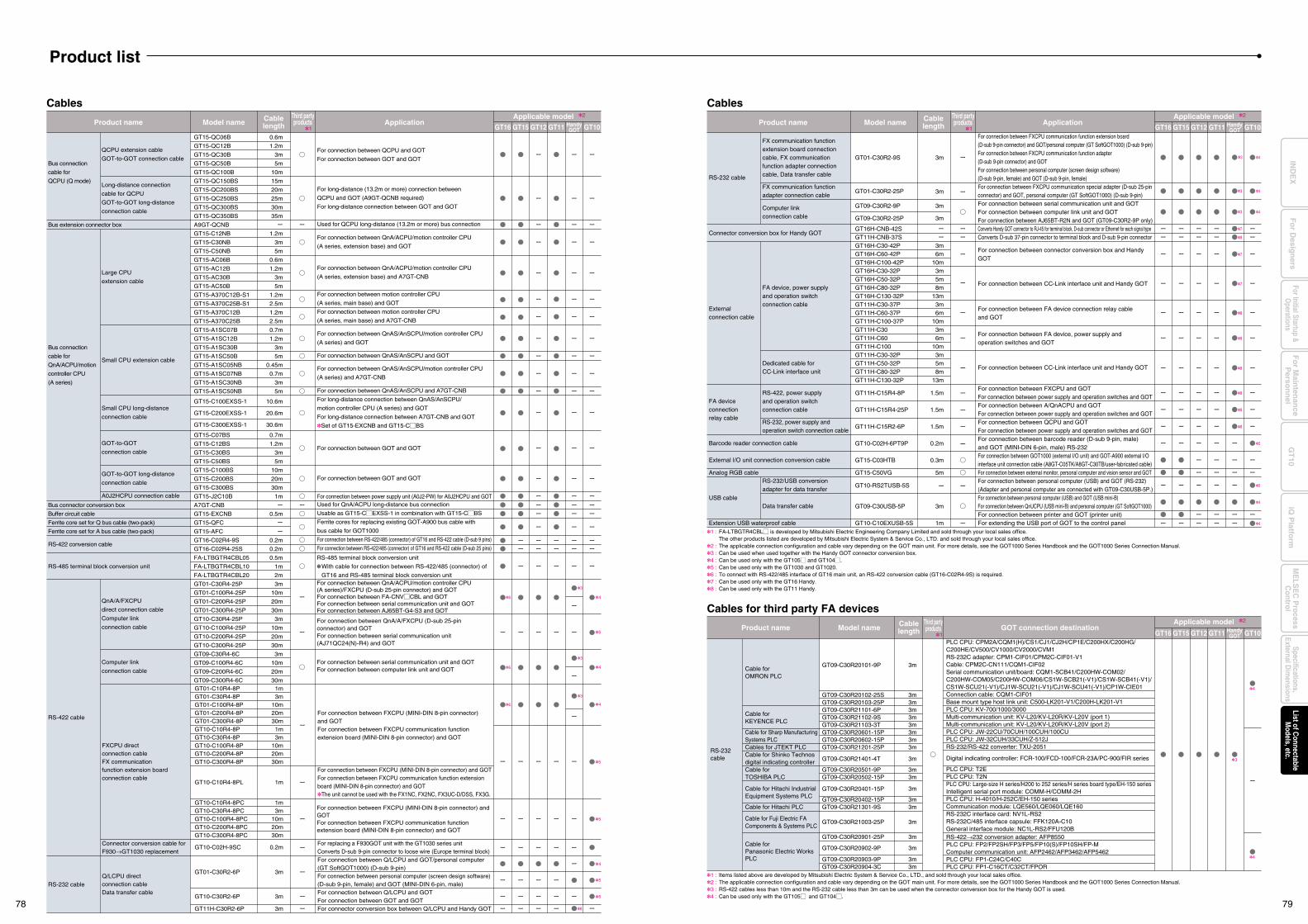
Bus connection
cable for
QCPU (Q mode)
Bus extension connector box
Bus connection
cable for
QnA/ACPU/motion
controller CPU
(A series)
Bus connector conversion box
Buffer circuit cable
Ferrite core set for Q bus cable (two-pack)
Ferrite core set for A bus cable (two-pack)
RS-422 conversion cable
RS-485 terminal block conversion unit
RS-422 cable
RS-232 cable
QCPU extension cable
GOT-to-GOT connection cable
Long-distance connection
cable for QCPU
GOT-to-GOT long-distance
connection cable
Large CPU
extension cable
Small CPU extension cable
Small CPU long-distance
connection cable
GOT-to-GOT
connection cable
GOT-to-GOT long-distance
connection cable
A0J2HCPU connection cable
QnA/A/FXCPU
direct connection cable
Computer link
connection cable
Computer link
connection cable
0.6m
1.2m
3m
5m
10m
15m
20m
25m
30m
35m
1.2m
3m
5m
0.6m
1.2m
3m
5m
1.2m
2.5m
1.2m
2.5m
0.7m
1.2m
3m
5m
0.45m
0.7m
3m
5m
10.6m
20.6m
30.6m
0.7m
1.2m
3m
5m
10m
20m
30m
1m
0.5m
0.2m
0.2m
0.5m
1m
2m
3m
10m
20m
30m
3m
10m
20m
30m
3m
10m
20m
30m
For connection between QCPU and GOT
For connection between GOT and GOT
For long-distance (13.2m or more) connection between
QCPU and GOT (A9GT-QCNB required)
For long-distance connection between GOT and GOT
Used for QCPU long-distance (13.2m or more) bus connection
For connection between QnA/ACPU/motion controller CPU
(A series, extension base) and GOT
For connection between QnA/ACPU/motion controller CPU
(A series, extension base) and A7GT-CNB
For connection between motion controller CPU
(A series, main base) and GOT
For connection between motion controller CPU
(A series, main base) and A7GT-CNB
For connection between QnAS/AnSCPU/motion controller CPU
(A series) and GOT
For connection between QnAS/AnSCPU and GOT
For connection between QnAS/AnSCPU/motion controller CPU
(A series) and A7GT-CNB
For connection between QnAS/AnSCPU and A7GT-CNB
For long-distance connection between QnAS/AnSCPU/
motion controller CPU (A series) and GOT
For long-distance connection between A7GT-CNB and GOT
Set of GT15-EXCNB and GT15-CMBS
For connection between GOT and GOT
For connection between GOT and GOT
For connection between power supply unit (A0J2-PW) for A0J2HCPU and GOTUsed for QnA/ACPU long-distance bus connection
Usable as GT15-CMEXSS-1 in combination with GT15-CMBS
Ferrite cores for replacing existing GOT-A900 bus cable with
bus cable for GOT1000
For connection between RS-422/485 (connector) of GT16 and RS-422 cable (D-sub 9 pins)
For connection between RS-422/485 (connector) of GT16 and RS-422 cable (D-sub 25 pins)
GT15-QC06B
GT15-QC12B
GT15-QC30B
GT15-QC50B
GT15-QC100B
GT15-QC150BS
GT15-QC200BS
GT15-QC250BS
GT15-QC300BS
GT15-QC350BS
A9GT-QCNB
GT15-C12NB
GT15-C30NB
GT15-C50NB
GT15-AC06B
GT15-AC12B
GT15-AC30B
GT15-AC50B
GT15-A370C12B-S1
GT15-A370C25B-S1
GT15-A370C12B
GT15-A370C25B
GT15-A1SC07B
GT15-A1SC12B
GT15-A1SC30B
GT15-A1SC50B
GT15-A1SC05NB
GT15-A1SC07NB
GT15-A1SC30NB
GT15-A1SC50NB
GT15-C100EXSS-1
GT15-C200EXSS-1
GT15-C300EXSS-1
GT15-C07BS
GT15-C12BS
GT15-C30BS
GT15-C50BS
GT15-C100BS
GT15-C200BS
GT15-C300BS
GT15-J2C10B
A7GT-CNB
GT15-EXCNB
GT15-QFC
GT15-AFC
GT16-C02R4-9S
GT16-C02R4-25S
FA-LTBGTR4CBL05
FA-LTBGTR4CBL10
FA-LTBGTR4CBL20
GT01-C30R4-25P
GT01-C100R4-25P
GT01-C200R4-25P
GT01-C300R4-25P
GT10-C30R4-25P
GT10-C100R4-25P
GT10-C200R4-25P
GT10-C300R4-25P
GT09-C30R4-6C
GT09-C100R4-6C
GT09-C200R4-6C
GT09-C300R4-6C
For connection between QnA/ACPU/motion controller CPU (A series)/FXCPU (D-sub 25-pin connector) and GOTFor connection between FA-CNVMCBL and GOTFor connection between serial communication unit and GOTFor connection between AJ65BT-G4-S3 and GOT
RS-485 terminal block conversion unit
With cable for connection between RS-422/485 (connector) of
GT16 and RS-485 terminal block conversion unit
For connection between QnA/A/FXCPU (D-sub 25-pin connector) and GOTFor connection between serial communication unit (AJ71QC24(N)-R4) and GOT
For connection between FXCPU (MINI-DIN 8-pin connector) and GOTFor connection between FXCPU communication function extension board (MINI-DIN 8-pin connector) and GOT
For connection between serial communication unit and GOTFor connection between computer link unit and GOT
4
3
6
6
6
3
4
3
4
4
5
5
GT15GT16 GT11GT12 GT10Product name Model name Cable
lengthThird partyproducts Application
GT15GT16 GT11GT12 HandyGOT GT10
GT15GT16 GT11GT12 HandyGOT GT10
Connector conversion box for Handy GOT
Externalconnection cable
FA device connection relay cable
Barcode reader connection cable
External I/O unit connection conversion cable
Analog RGB cable
USB cable
Extension USB waterproof cable
RS-232 cable
FX communication functionadapter connection cable
Computer link connection cable
FA device, power supply and operation switch connection cable
Dedicated cable for CC-Link interface unit
RS-422, power supply and operation switch connection cable
RS-232, power supply and operation switch connection cable
RS-232/USB conversion adapter for data transfer
Data transfer cable
3m
3m
3m
3m6m
10m3m5m8m
13m3m6m
10m3m6m
10m3m5m8m
13m
1.5m
1.5m
1.5m
0.2m
0.3m
5m
3m
1m
For connection between FXCPU communication special adapter (D-sub 25-pin connector) and GOT, personal computer (GT SoftGOT1000) (D-sub 9-pin)For connection between serial communication unit and GOTFor connection between computer link unit and GOTFor connection between AJ65BT-R2N and GOT (GT09-C30R2-9P only)Converts Handy GOT connector to RJ-45 for terminal block, D-sub connector or Ethernet for each signal typeConverts D-sub 37-pin connector to terminal block and D-sub 9-pin connector
For connection between connector conversion box and Handy GOT
For connection between CC-Link interface unit and Handy GOT
For connection between FA device connection relay cable and GOT
For connection between FA device, power supply and operation switches and GOT
For connection between CC-Link interface unit and Handy GOT
For connection between FXCPU and GOTFor connection between power supply and operation switches and GOTFor connection between A/QnACPU and GOTFor connection between power supply and operation switches and GOTFor connection between QCPU and GOTFor connection between power supply and operation switches and GOTFor connection between barcode reader (D-sub 9-pin, male) and GOT (MINI-DIN 6-pin, male) RS-232 For connection between GOT1000 (external I/O unit) and GOT-A900 external I/O interface unit connection cable (A8GT-C05TK/A8GT-C30TB/user-fabricated cable)For connection between external monitor, personal computer and vision sensor and GOTFor connection between personal computer (USB) and GOT (RS-232)(Adapter and personal computer are connected with GT09-C30USB-5P.)For connection between personal computer (USB) and GOT (USB mini-B)For connection between QnUCPU (USB mini-B) and personal computer (GT SoftGOT1000)For connection between printer and GOT (printer unit)For extending the USB port of GOT to the control panel
CablesCables
GT01-C30R2-25P
GT09-C30R2-9P
GT09-C30R2-25P
GT16H-CNB-42SGT11H-CNB-37SGT16H-C30-42PGT16H-C60-42PGT16H-C100-42PGT16H-C30-32PGT16H-C50-32PGT16H-C80-32PGT16H-C130-32PGT11H-C30-37PGT11H-C60-37PGT11H-C100-37PGT11H-C30GT11H-C60GT11H-C100GT11H-C30-32PGT11H-C50-32PGT11H-C80-32PGT11H-C130-32P
GT11H-C15R4-8P
GT11H-C15R4-25P
GT11H-C15R2-6P
GT10-C02H-6PT9P
GT15-C03HTB
GT15-C50VG
GT10-RS2TUSB-5S
GT09-C30USB-5P
GT10-C10EXUSB-5S
RS-232 cable
Cable for OMRON PLC
Cable for KEYENCE PLC
Cable for Sharp Manufacturing Systems PLCCables for JTEKT PLCCable for Shinko Technos digital indicating controllerCable for TOSHIBA PLC
Cable for Hitachi Industrial Equipment Systems PLC
Cable for Hitachi PLC
Cable for Fuji Electric FA Components & Systems PLC
Cable for Panasonic Electric WorksPLC
GT09-C30R20101-9P
GT09-C30R20102-25SGT09-C30R20103-25PGT09-C30R21101-6PGT09-C30R21102-9SGT09-C30R21103-3TGT09-C30R20601-15PGT09-C30R20602-15PGT09-C30R21201-25P
GT09-C30R21401-4T
GT09-C30R20501-9PGT09-C30R20502-15P
GT09-C30R20401-15P
GT09-C30R20402-15PGT09-C30R21301-9S
GT09-C30R21003-25P
3m
3m3m3m3m3m3m3m3m
3m
3m3m
3m
3m3m
3m
PLC CPU: CPM2A/CQM1(H)/CS1/CJ1/CJ2H/CP1E/C200HX/C200HG/C200HE/CV500/CV1000/CV2000/CVM1RS-232C adapter: CPM1-CIF01/CPM2C-CIF01-V1Cable: CPM2C-CN111/CQM1-CIF02Serial communication unit/board: CQM1-SCB41/C200HW-COM02/C200HW-COM05/C200HW-COM06/CS1W-SCB21(-V1)/CS1W-SCB41(-V1)/CS1W-SCU21(-V1)/CJ1W-SCU21(-V1)/CJ1W-SCU41(-V1)/CP1W-CIE01Connection cable: CQM1-CIF01Base mount type host link unit: C500-LK201-V1/C200H-LK201-V1PLC CPU: KV-700/1000/3000Multi-communication unit: KV-L20/KV-L20R/KV-L20V (port 1)Multi-communication unit: KV-L20/KV-L20R/KV-L20V (port 2)PLC CPU: JW-22CU/70CUH/100CUH/100CUPLC CPU: JW-32CUH/33CUH/Z-512JRS-232/RS-422 converter: TXU-2051
Digital indicating controller: FCR-100/FCD-100/FCR-23A/PC-900/FIR series
PLC CPU: T2EPLC CPU: T2NPLC CPU: Large-size H series/H200 to 252 series/H series board type/EH-150 seriesIntelligent serial port module: COMM-H/COMM-2HPLC CPU: H-4010/H-252C/EH-150 seriesCommunication module: LQE560/LQE060/LQE160RS-232C interface card: NV1L-RS2RS-232C/485 interface capsule: FFK120A-C10General interface module: NC1L-RS2/FFU120B
Product name Model name Cablelength GOT connection destination
Cables for third party FA devices
FXCPU direct connection cableFX communication function extension board connection cable
1m3m
10m20m30m1m3m
10m20m30m
1m
1m3m
10m20m30m
0.2m
For connection between FXCPU (MINI-DIN 8-pin connector) and GOTFor connection between FXCPU communication function extension board (MINI-DIN 8-pin connector) and GOT
GT01-C10R4-8PGT01-C30R4-8PGT01-C100R4-8PGT01-C200R4-8PGT01-C300R4-8PGT10-C10R4-8PGT10-C30R4-8PGT10-C100R4-8PGT10-C200R4-8PGT10-C300R4-8P
GT10-C10R4-8PL
GT10-C10R4-8PCGT10-C30R4-8PCGT10-C100R4-8PCGT10-C200R4-8PCGT10-C300R4-8PC
GT10-C02H-9SC
For connection between FXCPU communication function extension board (D-sub 9-pin connector) and GOT/personal computer (GT SoftGOT1000) (D-sub 9-pin)For connection between FXCPU communication function adapter (D-sub 9-pin connector) and GOTFor connection between personal computer (screen design software) (D-sub 9-pin, female) and GOT (D-sub 9-pin, female)
For connection between FXCPU (MINI-DIN 8-pin connector) and GOTFor connection between FXCPU communication function extension board (MINI-DIN 8-pin connector) and GOTThe unit cannot be used with the FX1NC, FX2NC, FX3UC-D/DSS, FX3G.
5
4
5
5
3m
3m
3m
GT01-C30R2-6P
GT10-C30R2-6P
GT11H-C30R2-6P
Q/LCPU direct connection cableData transfer cable
Connector conversion cable forF930→GT1030 replacement
For connection between Q/LCPU and GOT/personal computer (GT SoftGOT1000) (D-sub 9-pin)For connection between personal computer (screen design software) (D-sub 9-pin, female) and GOT (MINI-DIN 6-pin, male)For connection between Q/LCPU and GOT For connection between GOT and GOTFor connector conversion box between Q/LCPU and Handy GOT
For replacing a F930GOT unit with the GT1030 series unitConverts D-sub 9-pin connector to loose wire (Europe terminal block)
8
4
HandyGOT
Product name Model name Cablelength
Third partyproducts Application
1 1
Third partyproducts
1
Applicable model 2
3
4
4
3
3
43
Product list
1 :2 :3 :4 :
Items listed above are developed by Mitsubishi Electric System & Service Co., LTD., and sold through your local sales office.The applicable connection configuration and cable vary depending on the GOT main unit. For more details, see the GOT1000 Series Handbook and the GOT1000 Series Connection Manual.RS-422 cables less than 10m and the RS-232 cable less than 3m can be used when the connector conversion box for the Handy GOT is used.Can be used only with the GT105M and GT104M.
3mGT01-C30R2-9S
FX communication function extension board connection cable, FX communication function adapter connection cable, Data transfer cable
7
7
7
4
4
5
5
8
8
8
8
8
8
8
GT09-C30R20901-25P
GT09-C30R20902-9P
GT09-C30R20903-9PGT09-C30R20904-3C
3m
3m
3m3m
RS-422→232 conversion adapter: AFP8550PLC CPU: FP2/FP2SH/FP3/FP5/FP10(S)/FP10SH/FP-MComputer communication unit: AFP2462/AFP3462/AFP5462PLC CPU: FP1-C24C/C40CPLC CPU: FP1-C16CT/C32CT/FPOR
1 :
2 :3 :4 :5 :6 :7 :8 :
FA-LTBGTR4CBLM is developed by Mitsubishi Electric Engineering Company Limited and sold through your local sales office.The other products listed are developed by Mitsubishi Electric System & Service Co., LTD. and sold through your local sales office.The applicable connection configuration and cable vary depending on the GOT main unit. For more details, see the GOT1000 Series Handbook and the GOT1000 Series Connection Manual.Can be used when used together with the Handy GOT connector conversion box.Can be used only with the GT105M and GT104M.Can be used only with the GT1030 and GT1020.To connect with RS-422/485 interface of GT16 main unit, an RS-422 conversion cable (GT16-C02R4-9S) is required.Can be used only with the GT16 Handy.Can be used only with the GT11 Handy.
Applicable model 2
Applicable model 2
78 79
Fo
r Main
tenan
ceP
erson
nel
GT
10iQ
Platfo
rmFor Initial Startup &
Operations
Fo
r Desig
ners
Specifications,External D
imensions
ME
LSE
C P
rocessC
ontrolList of C
onnectableM
odels, etc.IN
DE
X
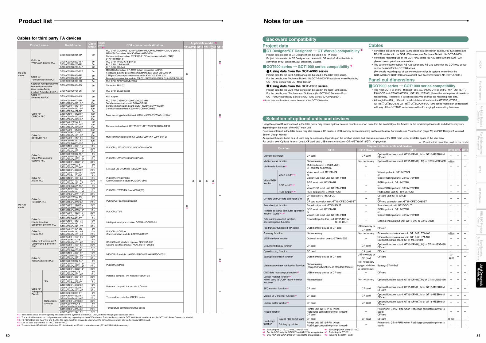
GT09-C30R40501-15PGT09-C100R40501-15PGT09-C200R40501-15PGT09-C300R40501-15PGT09-C30R40502-6CGT09-C100R40502-6CGT09-C200R40502-6CGT09-C300R40502-6CGT09-C30R40503-15PGT09-C100R40503-15PGT09-C200R40503-15PGT09-C300R40503-15PGT09-C30R40401-7TGT09-C100R40401-7TGT09-C200R40401-7TGT09-C300R40401-7T
3m10m20m30m3m
10m20m30m3m
10m20m30m3m
10m20m30m
PLC CPU: T2/T3/T3H/model3000(S3)
PLC CPU: T2E/model2000(S2)
PLC CPU: T2N
Intelligent serial port module: COMM-H/COMM-2H
Cables for third party FA devices
GT09-C30R41301-9SGT09-C100R41301-9SGT09-C200R41301-9SGT09-C300R41301-9SGT09-C30R41001-6TGT09-C100R41001-6TGT09-C200R41001-6TGT09-C300R41001-6TGT09-C30R40201-9PGT09-C100R40201-9PGT09-C200R40201-9PGT09-C300R40201-9PGT09-C30R40202-14PGT09-C100R40202-14PGT09-C200R40202-14PGT09-C300R40202-14PGT09-C30R40301-6TGT09-C100R40301-6TGT09-C200R40301-6TGT09-C300R40301-6TGT09-C30R40302-6TGT09-C100R40302-6TGT09-C200R40302-6TGT09-C300R40302-6TGT09-C30R40303-6TGT09-C100R40303-6TGT09-C200R40303-6TGT09-C300R40303-6TGT09-C30R40304-6TGT09-C100R40304-6TGT09-C200R40304-6TGT09-C300R40304-6T
3m10m20m30m3m
10m20m30m3m
10m20m30m3m
10m20m30m3m
10m20m30m3m
10m20m30m3m
10m20m30m3m
10m20m30m
PLC CPU: LQP510Communication module: LQE565/LQE165
RS-232C/485 interface capsule: FFK120A-C10General interface module: NC1L-RS4/FFU120B
MEMOBUS module: JAMSC-120NOM27100/JAMSC-IF612
PLC CPU: MP940
Personal computer link module: F3LC11-2N
Personal computer link module: LC02-0N
Temperature controller: GREEN series
Temperature controller: UT2000 series
RS-422cable
GT09-C30R40601-15PGT09-C100R40601-15PGT09-C200R40601-15PGT09-C300R40601-15PGT09-C30R40602-15PGT09-C100R40602-15PGT09-C200R40602-15PGT09-C300R40602-15PGT09-C30R40603-6TGT09-C100R40603-6TGT09-C200R40603-6TGT09-C300R40603-6TGT09-C30R41201-6CGT09-C100R41201-6CGT09-C200R41201-6CGT09-C300R41201-6C
3m10m20m30m3m
10m20m30m3m
10m20m30m3m
10m20m30m
PLC CPU: JW-22CU/70CUH/100CUH/100CU
PLC CPU: JW-32CUH/33CUH/Z-512J
Link unit: JW-21CM/JW-10CM/ZW-10CM
PLC CPU: PC3J/PC3JLCommunication module: PC/CMP2-LINK
GT15GT16 GT11GT12 HandyGOT GT10
Product name Model name Cablelength
Third partyproducts GOT connection destination
1
GT09-C30R40101-9PGT09-C100R40101-9PGT09-C200R40101-9PGT09-C300R40101-9PGT09-C30R40102-9PGT09-C100R40102-9PGT09-C200R40102-9PGT09-C300R40102-9PGT09-C30R40103-5TGT09-C100R40103-5TGT09-C200R40103-5TGT09-C300R40103-5TGT09-C30R41101-5TGT09-C100R41101-5TGT09-C200R41101-5TGT09-C300R41101-5T
3m10m20m30m3m
10m20m30m3m
10m20m30m3m
10m20m30m
PLC CPU: CV500/CV1000/CV2000/CVM1Serial communication unit: CJ1W-SCU41Serial communication board: CQM1-SCB41/CS1W-SCB41Communication board: C200HW-COM03/COM06
Base mount type host link unit: C200H-LK202-V1/C500-LK201-V1
Communication board: CP1W-CIF11/CP1W-CIF12/CJ1W-CIF11
Multi-communication unit: KV-L20/KV-L20R/KV-L20V (port 2)
Cable forOMRON PLC
Cable forKEYENCE PLC
Cable forSharp Manufacturing Systems PLC
Cable forJTEKT PLC
Cable forTOSHIBA PLC
Cable forHitachi IndustrialEquipment Systems PLC
Cable forHitachi PLC
Cable for Fuji Electric FAComponents & Systems PLC
Cable forYaskawa Electric PLC
Cable forYokogawaElectric
PLC
Temperaturecontroller
Product list
1 :2 :3 :4 :5 :
Items listed above are developed by Mitsubishi Electric System & Service Co., LTD., and sold through your local sales office.The applicable connection configuration and cable vary depending on the GOT main unit. For more details, see the GOT1000 Series Handbook and the GOT1000 Series Connection Manual.RS-422 cables less than 10m and the RS-232 cable less than 3m can be used when the connector conversion box for the Handy GOT is used.Can be used only with the GT105M and GT104M.To connect with RS-422/485 interface of GT16 main unit, an RS-422 conversion cable (GT16-C02R4-9S) is necessary.
1 :2 :3 :
Excluding the GT16MM-VNBM and GT1655.For the GT15, only the GT1585V and GT1575V are applicable.Only XGA and SVGA of the GT16 and GT15 are applicable.
4 :5 :6 :
Excluding QVGA of the GT155M.Excluding the GT155M.Including the GT11 Handy.
Memory extension CF cardOptional function board: GT15-QFNBMM or GT15-MESB48MCF card
Multi-channel function Not necessary Optional function board: GT15-QFNB(MM) or GT15-MESB48M
RGB output unit: GT16M-ROUT RGB output unit: GT15V-75ROUT
Notnecessary
Notnecessary
Sound output function Sound output unit: GT15-SOUT Sound output unit: GT15-SOUT
Gateway function
File transfer function (FTP client)
Not necessary
USB memory device or CF card
Ethernet communication unit: GT15-J71E71-100
Operation log function CF card CF card
Backup/restoration function USB memory device or CF card CF cardCF
card
CF card
CF card
CNC data input/output function3 USB memory device or CF card CF card
Maintenance time notification functionNot necessary (equipped with battery as standard feature)
Battery: GT15-BAT
MES interface function Optional function board: GT16-MESBEthernet communication unit: GT15-J71E71-100Optional function board: GT15-MESB48M
Document display function CF cardOptional function board: GT15-QFNB(MM) or GT15-MESB48MCF card
SFC monitor function4 CF cardOptional function board: GT15-QFNBMM or GT15-MESB48MCF card
Ladder editor function5 CF cardOptional function board: GT15-QFNBMM or GT15-MESB48MCF card
Report function
Hard copyfunction
Printer unit: GT15-PRN (when PictBridge-compatible printer is used)CF card
Printer unit: GT15-PRN (when PictBridge-compatible printer is used)CF card
External input/output function, operation panel function
External input/output unit: GT15-DIO or GT15-DIOR External input/output unit: GT15-DIO or GT15-DIOR
Ladder monitor function4
(when using Q/L/QnA ladder monitor function)
Not necessary Optional function board: GT15-QFNB(MM) or GT15-MESB48M
Multimedia function1
Video/RGB function
Multimedia unit: GT16M-MMRCF card for multimedia
CF card unit/CF card extension unitCF card unit: GT15-CFCD orCF card extension unit: GT15-CFEX-C08SET
CF card unit: GT15-CFCD orCF card extension unit: GT15-CFEX-C08SET
Video input unit: GT16M-V4 orVideo/RGB input unit: GT16M-V4R1
Video input unit: GT15V-75V4 orVideo/RGB input unit: GT15V-75V4R1
RGB input unit: GT16M-R2 orVideo/RGB input unit: GT16M-V4R1
RGB input unit: GT15V-75R1 orVideo/RGB input unit: GT15V-75V4R1
Remote personal computer operation function (serial)1 2
RGB input unit: GT16M-R2 orVideo/RGB input unit: GT16M-V4R1
RGB input unit: GT15V-75R1 orVideo/RGB input unit: GT15V-75V4R1
Video input1 2
RGB input1 2
RGB output1 2
CF card CF cardSaving files on CF card
Printer unit: GT15-PRN (when PictBridge-compatible printer is used)
Printer unit: GT15-PRN (when PictBridge-compatible printer is used)Printing by printer
FunctionRequired optional units and devices
GT16 GT16 Handy GT15 GT116 GT10GT12
Project data
Using the optional functions listed in the table below may require optional devices or units as shown. Note that the availability of the function or the required optional units and devices may vary depending on the model of the GOT main unit.Functions not listed in the table below may also require a CF card or a USB memory device depending on the application. For details, see "Function list" (page 70) and "GT Designer3 Version1 Screen Design Manual." An optional function board or a CF card may be necessary depending on the function version and hardware version of the GOT main unit or available space of the user area.For details, see "Optional function board, CF card, and USB memory selection <GT16/GT15/GT12/GT11>" (page 82).
Backward compatibility
Selection of optional units and devices
Cables• For details on using the GOT-A900 series bus connection cables, RS-422 cables and
RS-232 cables with the GOT1000 series, see Technical Bulletin No.GOT-A-0009.• For details regarding use of the GOT-F900 series RS-422 cable with the GOT1000,
please contact your local sales office.• The bus connection cables, RS-422 cables and RS-232 cables for the GOT1000 series
cannot be used for the GOT900 series.(For details regarding use of bus connection cables in systems where both the GOT-A900 and GOT1000 series coexist, see Technical Bulletin No. GOT-A-0009.)
Panel cut dimensionsGOT900 series → GOT1000 series compatibility• The A985GOT(-V) and GT1685/GT1585, A975/970GOT(-B) and GT167M/GT157M,
F940GOT and GT1655/GT155M/GT115M/GT105M have the same panel dimensions, respectively. Therefore, it is not necessary to change the mounting hole size.
• Although the A95M differs in panel cut dimensions from the GT1655, GT155M, GT115M-QMBDQ and GT115M-QMBDA, the GOT900 series model can be replaced with any of the GOT1000 series ones without changing the mounting hole size.
GT Designer/GT Designer2 → GT Works3 compatibility Project data created in GT Designer2 can be used in GT Works3.Project data created in GT Designer can be used in GT Works3 after the data is converted by GT Designer2/GT Designer2 Classic.
GOT900 series → GOT1000 series compatibility
Using data from the GOT-A900 seriesProject data for the GOT-A900 series can be used in the GOT1000 series.For the details, see Technical Bulletin No.GOT-A-0009 "Precautions when Replacing GOT-A900 Series with GOT1000 Series".
Using data from the GOT-F900 seriesProject data for the GOT-F900 series can be used in the GOT1000 series.For the details, see "Replacement Guidance (for GOT1000 Series) – From GOT-F900/A950 Handy Series to GOT1000 Series" (JY997D39301).
Some data and functions cannot be used in the GOT1000 series.
Notes for use
CF card
CF card
CF card
CF card
CF card
CF card
Motion SFC monitor function4 CF cardOptional function board: GT15-QFNBMM or GT15-MESB48MCF card
CF card
USB memory or
CF card
USB memory or
CF card
Not necessary
Not necessary
Not necessary
Not necessary
(equipped with battery
as standard feature)
: Function that cannot be used on the model
4
4
4
3
5
Cable for YASKAWA Electric PLC
GT09-C30R20201-9P
GT09-C30R20202-15PGT09-C30R20203-9PGT09-C30R20204-14P
GT09-C30R20205-25P
3m
3m3m3m
3m
PLC CPU: GL120/GL130/MP-920/MP-930/CP-9200(H)/PROGIC-8 (port 1)MEMOBUS module: JAMSC-IF60/JAMSC-IF61Communication module: 217IF/CP-217IF (when connected to CN1)/217IF-01/218IF-01PLC CPU: PROGIC-8 (port 2)PLC CPU: CP-9300MSPLC CPU: MP-940MEMOBUS module: CP-217IF (when connected to CN2)Yokogawa Electric personal computer module: LC01-0N/LC02-0N
Cable for Yokogawa Electric PLC
Cable for Yokogawa Electric temperature controllerCable for Allen-Bradley (Rockwell Automation, Inc.) PLCCable for Siemens AG PLC
GT09-C30R20301-9PGT09-C30R20302-9PGT09-C30R20305-9S
GT09-C30R20304-9S
GT09-C30R20701-9S
GT09-C30R20801-9S
3m3m3m
3m
3m
3m
CPU port/D-sub 9-pin conversion cable: KM10-0C/KM10-0SPersonal computer link module: F3LC01-1N/F3LC11-1N/F3LC11-1F/F3LC12-1FPLC CPU: NFCP100/NFJT100
Converter: ML2-M
PLC CPU: SL500 series
HMI adapter
RS-232 cable
Applicable model 2
80 81
Fo
r Main
tenan
ceP
erson
nel
GT
10iQ
Platfo
rmFor Initial Startup &
Operations
Fo
r Desig
ners
Specifications,External D
imensions
ME
LSE
C P
rocessC
ontrolList of C
onnectableM
odels, etc.IN
DE
X
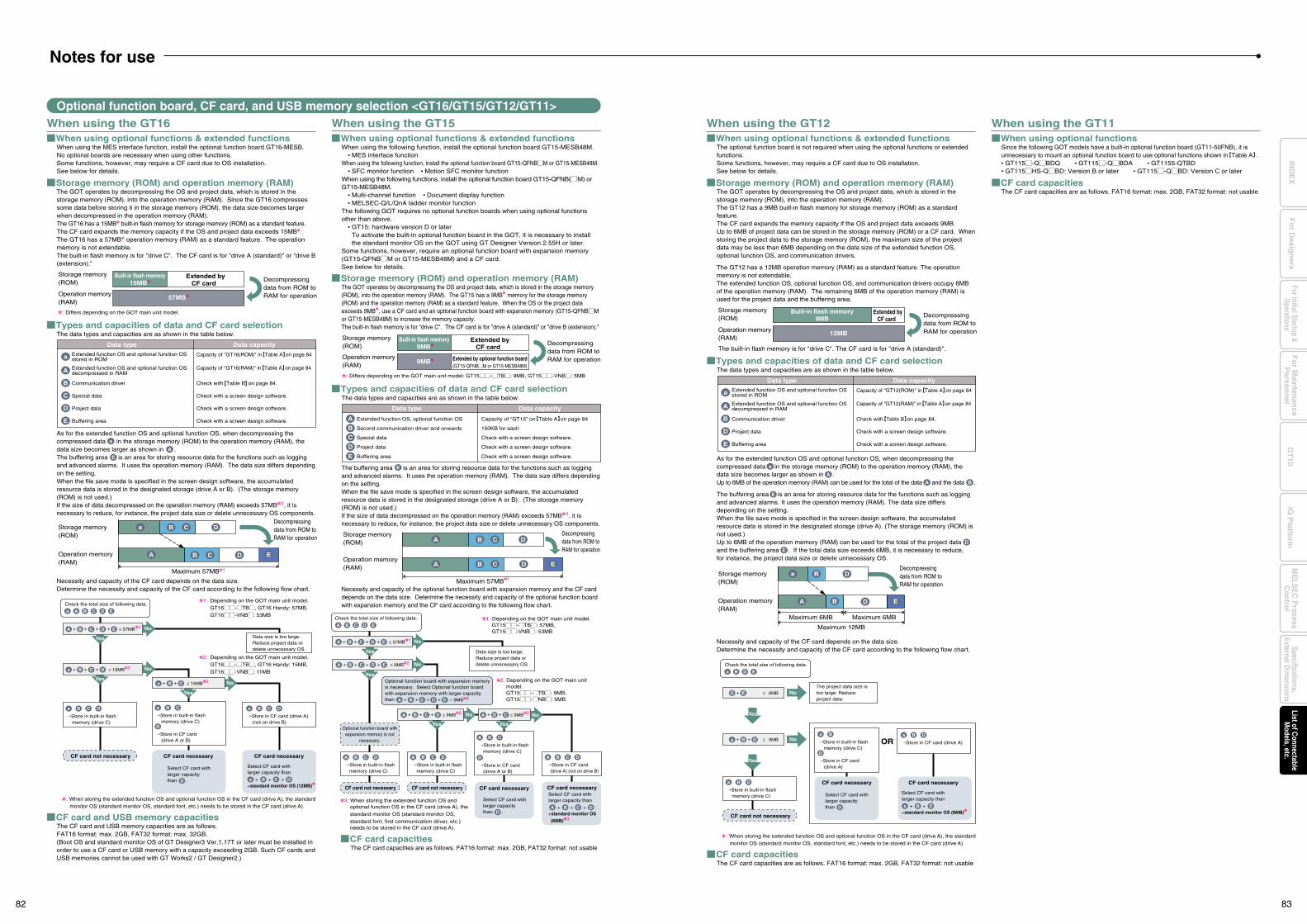
When using the GT16 When using optional functions & extended functions
When using the MES interface function, install the optional function board GT16-MESB. No optional boards are necessary when using other functions.Some functions, however, may require a CF card due to OS installation. See below for details.
Storage memory (ROM) and operation memory (RAM)The GOT operates by decompressing the OS and project data, which is stored in the storage memory (ROM), into the operation memory (RAM). Since the GT16 compresses some data before storing it in the storage memory (ROM), the data size becomes larger when decompressed in the operation memory (RAM).The GT16 has a 15MB built-in flash memory for storage memory (ROM) as a standard feature.The CF card expands the memory capacity if the OS and project data exceeds 15MB.The GT16 has a 57MB operation memory (RAM) as a standard feature. The operation memory is not extendable. The built-in flash memory is for "drive C". The CF card is for "drive A (standard)" or "drive B (extension)."
When using the GT15
Storage memory (ROM) and operation memory (RAM)The GOT operates by decompressing the OS and project data, which is stored in the storage memory (ROM), into the operation memory (RAM). The GT15 has a 9MB memory for the storage memory (ROM) and the operation memory (RAM) as a standard feature. When the OS or the project data exceeds 9MB, use a CF card and an optional function board with expansion memory (GT15-QFNBMM or GT15-MESB48M) to increase the memory capacity.The built-in flash memory is for "drive C". The CF card is for "drive A (standard)" or "drive B (extension)." Types and capacities of data and CF card selection
The data types and capacities are as shown in the table below.
As for the extended function OS and optional function OS, when decompressing the compressed data in the storage memory (ROM) to the operation memory (RAM), the data size becomes larger as shown in .The buffering area is an area for storing resource data for the functions such as logging and advanced alarms. It uses the operation memory (RAM). The data size differs depending on the setting.When the file save mode is specified in the screen design software, the accumulated resource data is stored in the designated storage (drive A or B). (The storage memory (ROM) is not used.)If the size of data decompressed on the operation memory (RAM) exceeds 57MB1, it is necessary to reduce, for instance, the project data size or delete unnecessary OS components.
Necessity and capacity of the CF card depends on the data size.Determine the necessity and capacity of the CF card according to the following flow chart.
CF card and USB memory capacitiesThe CF card and USB memory capacities are as follows.FAT16 format: max. 2GB, FAT32 format: max. 32GB.(Boot OS and standard monitor OS of GT Designer3 Ver.1.17T or later must be installed in order to use a CF card or USB memory with a capacity exceeding 2GB. Such CF cards and USB memories cannot be used with GT Works2 / GT Designer2.)
CF card capacitiesThe CF card capacities are as follows. FAT16 format: max. 2GB, FAT32 format: not usable
Optional function board, CF card, and USB memory selection <GT16/GT15/GT12/GT11>
Storage memory (ROM)
Operation memory (RAM)
Decompressing data from ROM toRAM for operation
Storage memory (ROM) Decompressing
data from ROM toRAM for operation Extended by optional function board
(GT15-QFNBMM or GT15-MESB48M) 9MB
Operation memory (RAM)
Data type Data capacityExtended function OS and optional function OSstored in ROM
Capacity of "GT16(ROM)" in Table A on page 84
Extended function OS and optional function OSdecompressed in RAM
a
A
Communication driverB
Special dataC
Project dataD
Buffering area
Capacity of "GT16(RAM)" in Table A on page 84
Check with Table B on page 84.
Check with a screen design software.
Check with a screen design software.
Check with a screen design software.E
Types and capacities of data and CF card selectionThe data types and capacities are as shown in the table below.
The buffering area is an area for storing resource data for the functions such as logging and advanced alarms. It uses the operation memory (RAM). The data size differs depending on the setting.When the file save mode is specified in the screen design software, the accumulated resource data is stored in the designated storage (drive A or B). (The storage memory (ROM) is not used.)If the size of data decompressed on the operation memory (RAM) exceeds 57MB1, it is necessary to reduce, for instance, the project data size or delete unnecessary OS components.
Necessity and capacity of the optional function board with expansion memory and the CF card depends on the data size. Determine the necessity and capacity of the optional function board with expansion memory and the CF card according to the following flow chart.
Data type Data capacity
Extended function OS, optional function OS
E
A
Second communication driver and onwardsB
Special dataC
Project dataD
Buffering area
Capacity of "GT15" on Table A on page 84
150KB for each
Check with a screen design software.
Check with a screen design software.
Check with a screen design software.E
: Differs depending on the GOT main unit model: GT15MM-MTBM: 9MB, GT15MM-VNBM: 5MB
Storage memory (ROM)
Operation memory (RAM)
a B C D
EB C DA
Storage memory (ROM)
Operation memory (RAM)
Decompressing data from ROM toRAM for operation
Decompressing data from ROM toRAM for operation B C D
EB C D
A
A
No
No
Yes
Yes
YesYes
Data size is too large.Reduce project data or delete unnecessary OS. Data size is too large.
Reduce project data or delete unnecessary OS.
No
Store in built-in flash memory (drive C)
Select CF card with larger capacity than .
CF card necessary
D
Select CF card with larger capacity than .D
Select CF card with larger capacity than
+standard monitor OS (12MB)
CF card necessary
+ + +a B C D
+ + + + ≤ 57MB1A B C D E
Yes
+ + + ≤ 15MB2a B C D
+ + ≤ 15MB2a B C
a B C D
Store in built-in flash memory (drive C)
a
Store in CF card (drive A or B)
D
B C
Store in CF card (drive A) (not on drive B)
a B C D
CF card not necessary
: When storing the extended function OS and optional function OS in the CF card (drive A), the standard monitor OS (standard monitor OS, standard font, etc.) needs to be stored in the CF card (drive A).
1 : Depending on the GOT main unit model. GT16MM-MTBM, GT16 Handy: 57MB, GT16MM-VNBM: 53MB
2 : Depending on the GOT main unit model. GT16MM-MTBM, GT16 Handy: 15MB, GT16MM-VNBM: 11MB
: Differs depending on the GOT main unit model.
No
No
Store in built-in flash memory (drive C)
CF card necessary CF card necessary
+ + + + ≤ 57MB1A B C D E
+ + + + ≤ 9MB2A B C D E
No
YesYes
+ + ≤ 9MB2A B CNo++ + ≤ 9MB2B CA D
A B C D
Store in built-in flash memory (drive C)
A B C D
Store in CF card (drive A) (not on drive B)
A B C D
CF card not necessary CF card not necessary
Store in built-in flash memory (drive C)
A
Store in CF card (drive A or B)
D
B C
Check the total size of following data.
Aa B C D E
Check the total size of following data.
A B C D E
Optional function board with expansion memory is necessary. Select Optional function board with expansion memory with larger capacity than
Optional function board withexpansion memory is not
necessary.
3: When storing the extended function OS and optional function OS in the CF card (drive A), the standard monitor OS (standard monitor OS, standard font, first communication driver, etc.) needs to be stored in the CF card (drive A).
1: Depending on the GOT main unit model. GT15MM-MTBM: 57MB, GT15MM-VNBM: 53MB
2: Depending on the GOT main unit model. GT15MM-MTBM: 9MB, GT15MM-MNBM: 5MB
57MB
Maximum 57MB1
Extended byCF card
Built-in flash memory 9MB
Maximum 57MB1
+ + + + – 9MB2A B C D E
Select CF card with larger capacity than
+standard monitor OS
(6MB)3
+ + +A B C D
Extended byCF card
Built-in flash memory15MB
A
E
a
Notes for use
When using optional functions & extended functionsWhen using the following function, install the optional function board GT15-MESB48M.• MES interface function
When using the following function, install the optional function board GT15-QFNBMM or GT15-MESB48M.• SFC monitor function • Motion SFC monitor function
When using the following functions, install the optional function board GT15-QFNB(MM) or GT15-MESB48M.• Multi-channel function • Document display function• MELSEC-Q/L/QnA ladder monitor function
The following GOT requires no optional function boards when using optional functions other than above.• GT15: hardware version D or laterTo activate the built-in optional function board in the GOT, it is necessary to install the standard monitor OS on the GOT using GT Designer Version 2.55H or later.
Some functions, however, require an optional function board with expansion memory (GT15-QFNBMM or GT15-MESB48M) and a CF card.See below for details.
When using the GT12 When using optional functions & extended functions
The optional function board is not required when using the optional functions or extended functions.Some functions, however, may require a CF card due to OS installation.See below for details.
Storage memory (ROM) and operation memory (RAM)The GOT operates by decompressing the OS and project data, which is stored in the storage memory (ROM), into the operation memory (RAM). The GT12 has a 9MB built-in flash memory for storage memory (ROM) as a standard feature.The CF card expands the memory capacity if the OS and project data exceeds 9MB.Up to 6MB of project data can be stored in the storage memory (ROM) or a CF card. When storing the project data to the storage memory (ROM), the maximum size of the project data may be less than 6MB depending on the data size of the extended function OS, optional function OS, and communication drivers.
The GT12 has a 12MB operation memory (RAM) as a standard feature. The operation memory is not extendable.The extended function OS, optional function OS, and communication drivers occupy 6MB of the operation memory (RAM). The remaining 6MB of the operation memory (RAM) is used for the project data and the buffering area.
CF card capacitiesThe CF card capacities are as follows. FAT16 format: max. 2GB, FAT32 format: not usable
When using the GT11
Types and capacities of data and CF card selectionThe data types and capacities are as shown in the table below.
As for the extended function OS and optional function OS, when decompressing the compressed data in the storage memory (ROM) to the operation memory (RAM), the data size becomes larger as shown in .Up to 6MB of the operation memory (RAM) can be used for the total of the data and the data .
The buffering area is an area for storing resource data for the functions such as logging and advanced alarms. It uses the operation memory (RAM). The data size differs depending on the setting.When the file save mode is specified in the screen design software, the accumulated resource data is stored in the designated storage (drive A). (The storage memory (ROM) is not used.)Up to 6MB of the operation memory (RAM) can be used for the total of the project data and the buffering area . If the total data size exceeds 6MB, it is necessary to reduce, for instance, the project data size or delete unnecessary OS.
E
A B
D
E
Necessity and capacity of the CF card depends on the data size.Determine the necessity and capacity of the CF card according to the following flow chart.
Storage memory (ROM)
Operation memory (RAM)
Decompressing data from ROM toRAM for operation
Data type Data capacityExtended function OS and optional function OSstored in ROM
Capacity of "GT12(ROM)" in Table A on page 84
Extended function OS and optional function OSdecompressed in RAM
a
A Capacity of "GT12(RAM)" in Table A on page 84
Check with Table B on page 84.
NoThe project data size is too large. Reduce project data.
+ ≤ 6MBD E
The built-in flash memory is for "drive C". The CF card is for "drive A (standard)".
Check the total size of following data.
a B
12MB
Extended byCF card
Built-in flash memory9MB
A
a
When using optional functionsSince the following GOT models have a built-in optional function board (GT11-50FNB), it is unnecessary to mount an optional function board to use optional functions shown in Table A .• GT115M-QMBDQ • GT115M-QMBDA • GT1155-QTBD• GT115MHS-QMBD: Version B or later • GT115M-QMBD: Version C or later
Communication driverB
CF card capacitiesThe CF card capacities are as follows. FAT16 format: max. 2GB, FAT32 format: not usable
Yes
Yes
No
Store in built-in flash memory (drive C) Select CF card with
larger capacity than .
CF card necessary
D
Select CF card with larger capacity than
+standard monitor OS (6MB)
CF card necessary
+a
+ ≤ 9MBa
a B D
Store in built-in flash memory (drive C)
a
Store in CF card (drive A)
D
Store in CF card (drive A)
a
CF card not necessary
: When storing the extended function OS and optional function OS in the CF card (drive A), the standard monitor OS (standard monitor OS, standard font, etc.) needs to be stored in the CF card (drive A).
B + D
B + D
ORB D
Check with a screen design software.
Check with a screen design software.
Project dataD
Buffering areaE
Storage memory (ROM)
Operation memory (RAM)
a B D
EDA B
Decompressing data from ROM toRAM for operation
Maximum 12MB
Maximum 6MBMaximum 6MB
D E
B
82 83
Fo
r Main
tenan
ceP
erson
nel
GT
10iQ
Platfo
rmFor Initial Startup &
Operations
Fo
r Desig
ners
Specifications,External D
imensions
ME
LSE
C P
rocessC
ontrolList of C
onnectableM
odels, etc.IN
DE
X
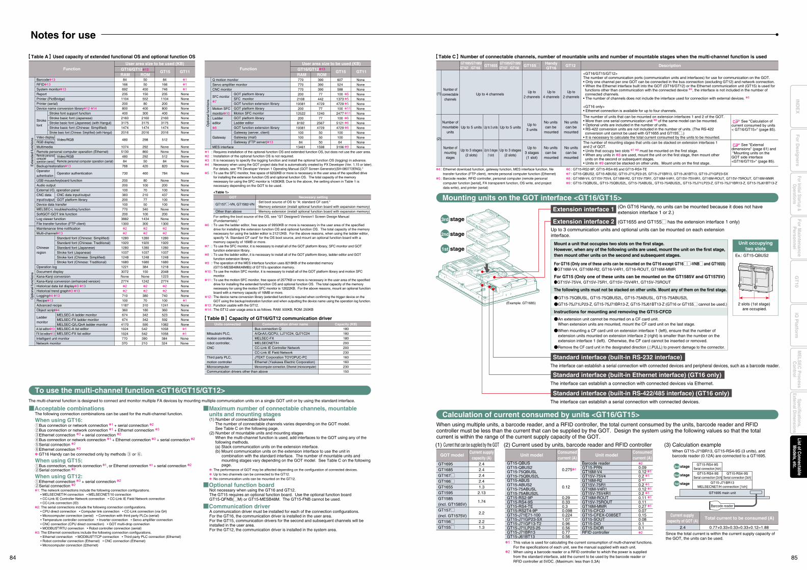
Notes for use
GT1595/GT1585/GT157M/GT156M
GT1695/GT1685/GT167M/GT166M GT155M
Number ofmounting
stages
Up to 3 stages(1 slot)
Up to 3 stages(2 slots)
Up to 3 stages(2 slots)
Up to3 stages(1 slot)
(2)
Number ofmountable
unitsUp to 3 units Up to 5 unitsUp to 5 units
Up to3 units
Number ofconnectable
channelsUp to 4 channels
Up to2 channels
HandyGT16
No units can be
mounted
No units can be
mounted
Up to4 channels
No unitscan be
mounted
No unitscan be
mounted
Up to2 channels
Description
The number of mounting stages that units can be stacked on extension interfaces 1 and 2 of GOT.• Units that occupy two slots 7 8 must be mounted on the first stage.• When any units in 8 are used, mount the unit on the first stage, then mount other units on the second or subsequent stages.
• Units in 9 cannot be stacked on other units. Mount units on the first stage.
The number of units that can be mounted on extension interfaces 1 and 2 of the GOT.• More than one serial communication unit 6 of the same model can be mounted.• Optional units are included in the number of units.• RS-422 conversion units are not included in the number of units. (The RS-422 conversion unit cannot be used with GT1655 and GT155M.)
• It is necessary to calculate the total current consumed by the units to be mounted.
<GT16/GT15/GT12>The number of communication ports (communication units and interfaces) for use for communication on the GOT.• Only one channel per one GOT can be connected in the bus connection (excluding GT12) and network connection.• When the Ethernet interface built into the GOT (GT16/GT12) or the Ethernet communication unit (GT15) is used for functions other than communication with the connected device 4, the interface is not included in the number of connected channels.
• The number of channels does not include the interface used for connection with external devices. 5
<GT16 only>• Ethernet connection is available for up to four channels.
See "Calculation of current consumed by units < GT16/GT15>" (page 85).
See "External dimensions" (page 61) and "Mounting units on the GOT side interface <GT16/GT15>" (page 85).
4 :
5 :
6 :7 :8 :9 :
GT15-RS2-9P, GT15-RS4-9S and GT15-RS4-TEGT15-QBUS2, GT15-ABUS2, GT15-J71LP23-25, GT15-J71BR13, GT15-J61BT13, GT15-J71GP23-SXGT16M-V4, GT15V-75V4, GT16M-R2, GT15V-75R1, GT16M-V4R1, GT15V-75V4R1, GT16M-ROUT, GT15V-75ROUT, GT16M-MMRGT15-75QBUSL, GT15-75QBUS2L, GT15-75ABUSL, GT15-75ABUS2L, GT15-75J71LP23-Z, GT15-75J71BR13-Z, GT15-75J61BT13-Z
Ethernet download function, gateway function, MES interface function, filetransfer function (FTP client), remote personal computer function (Ethernet)Barcode reader, RFID controller, personal computer (remote personal computer function [serial], FA transparent function, OS write, and projectdata write), and printer (serial)
GT1695GT1685GT167MGT166MGT1655GT1595GT1585(incl. GT1585V)GT157M(incl. GT1575V)GT156MGT155M
GOT model Unit modelConsumedcurrent (A)
Unit modelConsumedcurrent (A)
Mounting units on the GOT interface <GT16/GT15>
Calculation of current consumed by units <GT16/GT15>When using multiple units, a barcode reader, and a RFID controller, the total current consumed by the units, barcode reader and RFID controller must be less than the current that can be supplied by the GOT. Design the system using the following values so that the total current is within the range of the current supply capacity of the GOT.
Extension interface 1
Extension interface 2
Standard interface (built-in RS-232 interface)The interface can establish a serial connection with connected devices and peripheral devices, such as a barcode reader.
Standard interface (built-in Ethernet interface) (GT16 only)The interface can establish a connection with connected devices via Ethernet.
Standard interface (built-in RS-422/485 interface) (GT16 only)The interface can establish a serial connection with connected devices.
Mount a unit that occupies two slots on the first stage.However, when any of the following units are used, mount the unit on the first stage, then mount other units on the second and subsequent stages.
Instructions for mounting and removing the GT15-CFCD
For GT16 (Only one of these units can be mounted on the GT16 except GT16MM-VNBM and GT1655)GT16M-V4, GT16M-R2, GT16-V4R1, GT16-ROUT, GT16M-MMR
For GT15 (Only one of these units can be mounted on the GT1585V and GT1575V)GT15V-75V4, GT15V-75R1, GT15V-75V4R1, GT15V-75ROUT
GT15-75QBUSL, GT15-75QBUS2L, GT15-75ABUSL, GT15-75ABUS2L
GT15-75J71LP23-Z, GT15-75J71BR13-Z, GT15-75J61BT13-Z (GT16 or GT155M cannot be used.)
The following units must not be stacked on other units. Mount any of them on the first stage.
(1) Current that can be supplied by the GOT
2.4 0.77+0.33+0.33+0.33+0.12=1.88
Current supply capacity of GOT (A)
Total current to be consumed (A)
(3) Calculation example(2) Current used by units, barcode reader and RFID controller
GT15-RS4-9SSerial connection [4ch]
GT15-J71BR13MELSECNET/H connection [1ch]
GT1695 main unit
Barcode reader
GT15-RS4-9SSerial connection [2ch]
GT15-RS4-9SSerial connection [3ch]
When GT15-J71BR13, GT15-RS4-9S (3 units), and barcode reader (0.12A) are connected to a GT1695.
Since the total current is within the current supply capacity of the GOT, the units can be used.
Ex.: GT15-QBUS2
2 slots (1st stage) are occupied.
Unit occupyingtwo slots
Up to 3 communication units and optional units can be mounted on each extension interface.
An extension unit cannot be mounted on a CF card unit.When extension units are mounted, mount the CF card unit on the last stage.
When mounting a CF card unit on extension interface 1 (left), ensure that the number of extension units mounted on extension interface 2 (right) is smaller than the number on the extension interface 1 (left). Otherwise, the CF card cannot be inserted or removed.
Remove the CF card unit in the designated direction (PULL) to prevent damage to the connector.
(GT1655 and GT155M has the extension interface 1 only)
(On GT16 Handy, no units can be mounted because it does not have extension interface 1 or 2.)
(Example: GT1685)
stage
stage
stage
3rd
2nd
1st
1 :
2 :
This value is used for calculating the current consumption of multi-channel functions. For the specifications of each unit, see the manual supplied with each unit.When using a barcode reader or a RFID controller to which the power is supplied from the standard interface, add the current to be used by the barcode reader or RFID controller at 5VDC. (Maximum: less than 0.3A)
2.42.42.42.41.3
2.13
1.74
2.2
2.21.3
Current supplycapacity (A)
stage3rd
stage2nd
stage1st
GT15-QBUSGT15-QBUS2GT15-75QBUSLGT15-75QBUS2LGT15-ABUSGT15-ABUS2GT15-75ABUSLGT15-75ABUS2LGT15-RS2-9PGT15-RS4-9SGT15-RS4-TEGT15-RS2T4-9PGT15-J71E71-100GT15-J71GP23-SXGT15-J71GF13-T2GT15-J71LP23-25GT15-J71BR13GT15-J61BT13
0.2751
0.12
0.290.330.30.0980.2241.070.960.560.770.56
Barcode readerGT15-PRNGT16M-V4GT15V-75V4GT16M-R2GT15V-75R1GT16M-V4R1GT15V-75V4R1GT16M-ROUTGT15V-75ROUTGT16M-MMRGT15-CFCDGT15-CFEX-C08SETGT15-SOUTGT15-DIOGT15-DIORRFID controller
20.090.12 1
0.2 1
0 1
0.2 1
0.12 1
0.2 1
0.11 1
0.110.27 1
0.070.150.080.10.12
(1)
GT1655 GT12
Table C Number of connectable channels, number of mountable units and number of mountable stages when the multi-channel function is used
To use the multi-channel function <GT16/GT15/GT12>
Acceptable combinationsThe following connection combinations can be used for the multi-channel function.
When using GT16:qBus connection or network connection 1 + serial connection 2
wBus connection or network connection 1 + Ethernet connection 3
eEthernet connection 3 + serial connection 2
rBus connection or network connection 1 + Ethernet connection 3 + serial connection 2
tSerial connection 2
yEthernet connection 3
GT16 Handy can be connected only by methods e or y.
When using GT15:qBus connection, network connection 1, or Ethernet connection 3 + serial connection 2
wSerial connection 2
When using GT12:qEthernet connection 3 + serial connection 2
wSerial connection 2
1: The network connections include the following connection configurations.• MELSECNET/H connection • MELSECNET/10 connection • CC-Link IE Controller Network connection • CC-Link IE Field Network connection• CC-Link connection (ID)
2: The serial connections include the following connection configurations.• CPU direct connection • Computer link connection • CC-Link connection (via G4)• Microcomputer connection (serial) • Connection with third party PLCs (serial)• Temperature controller connection • Inverter connection • Servo amplifier connection • CNC connection (CPU direct connection) • GOT multi-drop connection • MODBUS®/RTU connection • Robot controller connection (serial)
3: The Ethernet connections include the following connection configurations.• Ethernet connection • MODBUS®/TCP connection • Third party PLC connection (Ethernet)• Robot controller connection (Ethernet) • CNC connection (Ethernet) • Microcomputer connection (Ethernet)
Maximum number of connectable channels, mountable units and mounting stages
(1) Number of connectable channelsThe number of connectable channels varies depending on the GOT model.See Table C on the following page.
(2) Number of mountable units and mounting stagesWhen the multi-channel function is used, add interfaces to the GOT using any of the following methods.(a) Stack communication units on the extension interface.(b) Mount communication units on the extension interface to use the unit in
combination with the standard interface. The number of mountable units and mounting stages vary depending on the GOT model. See Table C on the following page.
: The performance of GOT may be affected depending on the configuration of connected devices.: Up to two channels can be connected to the GT12.: No communication units can be mounted on the GT12.
Optional function boardNot necessary when using the GT16 and GT12.The GT15 requires an optional function board. Use the optional function board GT15-QFNB(MM) or GT15-MESB48M. The GT15-FNB cannot be used.
Communication driver A communication driver must be installed for each of the connection configurations.For the GT16, the communication driver is installed in the user area.For the GT15, communication drivers for the second and subsequent channels will be installed in the user area.For the GT12, the communication driver is installed in the system area.
Barcode13RFID13System monitor13ReportPrinter (PictBridge)Printer (serial)Device name conversion library12 14
Strokefont
Video displayRGB displayMultimediaRemote personal computer operation (Ethernet)
Backup/restoration13OperatorauthenticationUSB mouse/keyboard functionAudio outputExternal I/O, operation panelCNC datainput/outputDevice data transferMELSEC-L troubleshooting functionSoftGOT-GOT link functionLog viewer functionFile transfer function (FTP client)Maintenance time notificationMulti-channel13
Chinese region
Operation logDocument displayKana-Kanji conversionKana-Kanji conversion (enhanced version)Historical data list display3 13Historical trend graph3 13Logging4 13Recipe13Advanced recipeObject script4
Ladder monitor
Stroke font support functionStroke basic font (Japanese)Stroke basic font (Japanese) (with Hangul)Stroke basic font (Chinese: Simplified)Stroke basic font (Chinese: Simplified) (with Hangul)
Video/RGB
Video/RGBRemote personal computer operation (serial)
Operator authentication
CNC data input/outputGOT platform library
Standard font (Chinese: Simplified)Standard font (Chinese: Traditional)Standard font (Japanese)Stroke font (Japanese)Stroke font (Chinese: Simplified)Stroke font (Chinese: Traditional)
MELSEC-A ladder monitorMELSEC-FX ladder monitorMELSEC-Q/L/QnA ladder monitorMELSEC-A list editorMELSEC-FX list editor
84166692235
1104200800400
2160317514742016
480
1074513048084
766
730
200200100383200100770200
3882130022
12801920128010371248168012213072None277422710100
1187360674674
4170
5050
45015055280
400300
2160317514742016
298
29286029250
420
460
8010070
2107750
340100
143430022
128019201280103712481680384150
None12422238070
310180342342590
84166746235
1104200800400
2160317514742016
512
NoneNone51284
820
784
None200100437100100
None200
None130022
128019201280103712481680121820481223277422740100
1241360523592
1082
111
NoneNoneNoneNoneNoneNoneNoneNoneNone
None
NoneNoneNoneNoneNone
None
NoneNoneNoneNoneNoneNoneNoneNoneNoneNoneNoneNoneNoneNoneNoneNoneNoneNoneNoneNoneNoneNoneNoneNoneNone
1NoneNoneNoneNoneNone
Function GT16/GT1213
RAM ROMGT11GT15
User area size to be used (KB)Function GT16/GT1213
RAM ROMGT11GT15
User area size to be used (KB)
1 : Requires installation of the optional function OS and extended function OS, but does not use the user area.2 : Installation of the optional function OS is not required.3 : It is necessary to specify the logging function and install the optional function OS (logging) in advance.4 : Necessary when using the GOT project data that is automatically created by PX Developer (Ver. 1.15 or later).
For details, see "PX Developer Version 1 Operating Manual (GOT Screen Generator)(SH-080772ENG)."5 : To use the SFC monitor, free space of 6202KB or more is necessary in the user area of the specified drive
for installing the extension function OS and optional function OS. The total capacity of the memory necessary for using the SFC monitor is 14393KB. Due to the above, the setting shown in Table 1 is necessary depending on the GOT to be used.
<Table 1>
For setting the boot source of the OS, see "GT Designer3 Version1 Screen Design Manual (Fundamentals)."
6 : To use the ladder editor, free space of 9950KB or more is necessary in the user area of the specified drive for installing the extension function OS and optional function OS. The total capacity of the memory necessary for using the ladder editor is 21212KB. For the above reasons, when using the ladder editor, specify "A: Standard CF card" for the OS boot source, and mount an optional function board with a memory capacity of 16MB or more.
7 : To use the SFC monitor, it is necessary to install all of the GOT platform library, SFC monitor and GOT function extension library.
8 : To use the ladder editor, it is necessary to install all of the GOT platform library, ladder editor and GOT function extension library.
9 : The operation of the MES interface function uses 8218KB of the extended memory (GT15-MESB48M(48MB)) of GT15's operation memory.
10 : To use the motion SFC monitor, it is necessary to install all of the GOT platform library and motion SFC monitor.
11 : To use the motion SFC monitor, free space of 2577KB or more is necessary in the user area of the specified drive for installing the extended function OS and optional function OS. The total capacity of the memory necessary for using the motion SFC monitor is 12622KB. For the above reasons, mount an optional function board with a memory capacity of 16MB or more.
12 : The device name conversion library (extended function) is required when confirming the trigger device on the GOT using the backup/restoration function and when outputting the device name using the operation log function.
13 : Function usable with the GT12.14 : The GT12 user usage area is as follows. RAM: 500KB, ROM: 250KB
Q motion monitorServo amplifier monitorCNC monitor
SFC monitor7
Motion SFC monitor10Ladder editor8
Gateway
MES interface
GOT platform librarySFC monitorGOT function extension libraryGOT platform libraryMotion SFC monitorGOT platform libraryLadder editorGOT function extension libraryGateway (server, client)Gateway (mail)Gateway (FTP server)13
6075245881001373472910024771005121472910010064
3196
390390390774424729
771240
7725674729
505050
1598
770770770200210819381
20012522
200819219381
10010084
13461
NoneNoneNoneNoneNoneNoneNoneNoneNoneNoneNoneNoneNoneNoneNone
A list editor13FX list editor13Intelligent unit monitorNetwork monitor
10581058384324
542542390210
10241024770370
11
NoneNone
The multi-channel function is designed to connect and monitor multiple FA devices by mounting multiple communication units on a single GOT unit or by using the standard interface.
Units connected
Mitsubishi PLC, motion controller,robot controller,CNC
Third party PLC,motion controllerMicrocomputerCommunication drivers other than above
Communication driver name Capacity (KB)Bus connection Q A/QnA/L/QCPU, LJ71C24, QJ71C24MELSEC-FXMELSECNET/HCC-Link IE Controller NetworkCC-Link IE Field NetworkJTEKT Corporation TOYOPUC-PCEthernet (Yaskawa Electric Corporation)Microcomputer connection, Ethernet (microcomputer)
180180180200200230160160230150
Table A Used capacity of extended functional OS and optional function OS
Table B Capacity of GT16/GT12 communication driver
Remote personalcomputeroperation (serial)
Opt
iona
l fun
ctio
ns
Ext
ende
d fu
nctio
nsO
ptio
nal f
unct
ions
GT157M-VN, GT1562-VN
Other than above
· Set boot source of OS to "A: standard CF card."· Memory extension (install optional function board with expansion memory)· Memory extension (install optional function board with expansion memory)
GOT Necessary setting
5551111666
9
84 85
Fo
r Main
tenan
ceP
erson
nel
GT
10iQ
Platfo
rmFor Initial Startup &
Operations
Fo
r Desig
ners
Specifications,External D
imensions
ME
LSE
C P
rocessC
ontrolList of C
onnectableM
odels, etc.IN
DE
X
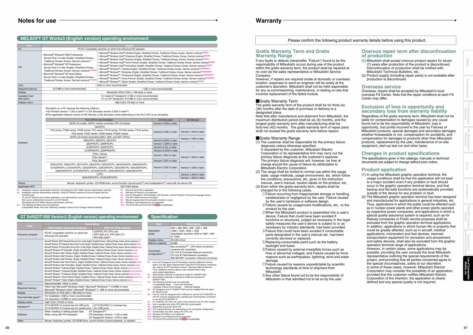
GT SoftGOT1000 Version3 (English version) operating environment
MELSOFT GT Works3 (English version) operating environment
DescriptionWith DOS/V personal computer With PC CPU module
Item
Specification
DescriptionItem
Resolution(dots)
640 × 480, 800 × 600, 1024 × 768,1280 × 1024, 1600 × 1200Specifiable resolution (640 to 1920 × 480 to 1200)
Display colorsMemory capacity
Connectionconfiguration10
1 : Use of GT Designer3 and PX Developer requires additional memory space. For free space required when using the PX Developer monitoring tool, refer to the PX Developer Version1 Operation Manual (Monitor Tool). Additional memory space is also required when using user-created applications.
2 : Administrator authority is required to install GT SoftGOT1000.3 : Administrator authority is required to install and operate GT
SoftGOT1000.4 : The following functions are not supported. • Compatibility Mode • Fast User Switching • Desktop Theme (Font) Change • Remote Desktop5 : GT Designer3 and GT SoftGOT1000 must be installed from the same
GT Works3 suite.6 : The PC must be equipped with a USB port to use the GT15-SGTKEY-U. The PC must be equipped with a parallel port (Centro/printer connector)
to use the GT15-SGTKEY-P.7 : For CONTEC PC CPU unit, refer to the manual for the PC CPU module.8 : Use is possible only when PPC-852-226 is preinstalled.9 : Supported only by the 32-bit OS.10 : The required devices vary depending on the connection configuration.11 : Connectable only when using a PC CPU unit.12 : Windows XP Mode is not supported.13 : Windows Touch features are not supported.14 : The 32-bit OS and the 64-bit OS are applicable.
1 : Installation requires administrator authority. Simulating the GOT-A900 requires administrator authority.2 : Installation requires administrator authority. Using GT Works3 requires an account higher than the
standard user. To use GT Works3 with another application, if an administrator account is used to run the application
then use an administrator account to run GT Works3. Simulating the GOT-A900 requires administrator authority.3 : The following functions are not supported: Compatibility Mode, Fast User Switching, Desktop Theme (Font) Change, Remote Desktop
4 : Only the 32-bit OS is applicable.5 : Windows XP Mode is not supported.6 : Use GT Simulator3, GX Developer, GX Simulator, and GX Works2 of the same language version.7 : The GOT-A900 cannot be simulated.8 : May be required when the simulation function is used.9 : Windows Touch features are not supported.10 : The 32-bit OS and the 64-bit OS are applicable.
65,536 colors57MBBus connection11, CPU direct connection, computer link connection,CC-Link IE Controller Network connection, CC-Link IE Field Network connection, MELSECNET connection, Ethernet connection
1 GHz or more recommended
• Microsoft® Windows Vista® Ultimate (English, Simplified Chinese, Traditional Chinese, Korean, German versions)234
• Microsoft® Windows Vista® Enterprise (English, Simplified Chinese, Traditional Chinese, Korean, German versions)234
• Microsoft® Windows Vista® Business (English, Simplified Chinese, Traditional Chinese, Korean, German versions)234
• Microsoft® Windows Vista® Home Premium (English, Simplified Chinese, Traditional Chinese, Korean, German versions)234
• Microsoft® Windows Vista® Home Basic (English, Simplified Chinese, Traditional Chinese, Korean, German versions)234
• Microsoft® Windows® 7 Ultimate (English, Simplified Chinese, Traditional Chinese, Korean, German versions)235910
• Microsoft® Windows® 7 Enterprise (English, Simplified Chinese, Traditional Chinese, Korean, German versions)235910
• Microsoft® Windows® 7 Professional (English, Simplified Chinese, Traditional Chinese, Korean, German versions)235910
• Microsoft® Windows® 7 Home Premium (English, Simplified Chinese, Traditional Chinese, Korean, German versions)23910
• Microsoft® Windows® 7 Starter (English, Simplified Chinese, Traditional Chinese, Korean, German versions)234
• Microsoft® Windows® 2000 Professional Service Pack 4 or later (English, Simplified Chinese, Traditional Chinese, Korean, German versions)1
• Microsoft® Windows® XP Professional Service Pack 2 or later (English, Simplified Chinese, Traditional Chinese, Korean, German versions)134
• Microsoft® Windows® XP Home Edition Service Pack 2 or later (English, Simplified Chinese, Traditional Chinese, Korean, German versions)134
To install GT Designer3: 2 GB or more recommendedTo run GT Designer3: 512 MB or more recommended
Simulation on a PC requires the following software:• GX Works2 version 1.12N or later6 or GX Simulator version 5.00A or later6.The applicable software version of GX Works2 or GX Simulator varies depending on the PLC CPU to be simulated.
Version 5.00A or later
Version 5.40E or later
Version 6.00A or laterVersion 7.20W or laterVersion 6.10L or laterVersion 6.20W or later
Version 7.22Y or later
Version 7.23Z or later
QCPU (A mode), ACPU, motion controller CPU (A series)QnACPU
FX0 series, FX0N series, FX0S series, FX1 series, FX1N series, FX1NC series, FX1S series, FX2 series, FX2C series, FX2N series, FX2NC series
QCPU (Q mode) (excluding Q00J, Q00, and Q01 CPUs)Q00JCPU, Q00CPU, Q01CPU
Q02PHCPU, Q06PHCPUQ12PHCPU, Q25PHCPU
Q12PRHCPU, Q25PRHCPUFX3UC SeriesFX3U Series7
FX3G Series7
LCPUQ50UDEHCPU, Q100UDEHCPU
Q00UJCPU, Q00UCPU, Q01UCPU, Q02UCPU, Q03UDCPU, Q04UDHCPU, Q06UDHCPU,Q10UDHCPU, Q13UDHCPU, Q20UDHCPU, Q26UDHCPU, Q03UDECPU, Q04UDEHCPU,
Q06UDEHCPU, Q10UDEHCPU, Q13UDEHCPU, Q20UDEHCPU, Q26UDEHCPU
PC
OS
CPURequired memoryDisplay
Available harddisk space
Display colors
Software
OthersApplicable GOT
Item Details
PLC CPU to be simulated
Version 7.08J or later
512 MB or more recommended 1 GB or more recommended
PC/AT compatible machine on which the following OS operates
Mouse, keyboard, printer, CD-ROM drive, sound function (sound card)8 and loudspeakers8 used with the above OSGOT1000 Series
Resolution XGA (1024 × 768 dots) or more
High Color (16 bits) or more
GX Simulator GX Works2
Version 1.24A or later
Version 1.12N or later
Version 1.24A or later
Version 1.12N or later
Version 1.24A or laterVersion 1.30G or later
Please confirm the following product warranty details before using this product.
Gratis Warranty Term and Gratis Warranty RangeIf any faults or defects (hereinafter "Failure") found to be the responsibility of Mitsubishi occurs during use of the product within the gratis warranty term, the product shall be repaired at no cost via the sales representative or Mitsubishi Service Company.However, if repairs are required onsite at domestic or overseas location, expenses to send an engineer will be solely at the customer's discretion. Mitsubishi shall not be held responsible for any re-commissioning, maintenance, or testing on-site that involves replacement of the failed module.
Gratis Warranty TermThe gratis warranty term of the product shall be for thirty-six (36) months after the date of purchase or delivery to a designated place.Note that after manufacture and shipment from Mitsubishi, the maximum distribution period shall be six (6) months, and the longest gratis warranty term after manufacturing shall be forty-two (42) months. The gratis warranty term of repair parts shall not exceed the gratis warranty term before repairs.
Gratis Warranty Range(1) The customer shall be responsible for the primary failure
diagnosis unless otherwise specified.If requested by the customer, Mitsubishi Electric Corporation or its representative firm may carry out the primary failure diagnosis at the customer's expense.The primary failure diagnosis will, however, be free of charge should the cause of failure be attributable to Mitsubishi Electric Corporation.
(2) The range shall be limited to normal use within the usage state, usage methods, usage environment, etc. which follow the conditions, precautions, etc. given in the instruction manual, user's manual, caution labels on the product, etc.
(3) Even within the gratis warranty term, repairs shall be charged for in the following cases.1Failure occurring from inappropriate storage or handling,
carelessness or negligence by the user. Failure caused by the user's hardware or software design.
2Failure caused by unapproved modifications, etc., to the product by the user.
3When the Mitsubishi product is assembled into a user's device, Failure that could have been avoided if functions or structures, judged as necessary in the legal safety measures the user's device is subject to or as necessary by industry standards, had been provided.
4Failure that could have been avoided if consumable parts designated in the user's manual etc. had been correctly serviced or replaced.
5Replacing consumable parts such as the battery, backlight and fuses.
6Failure caused by external irresistible forces such as fires or abnormal voltages, and Failure caused by force majeure such as earthquakes, lightning, wind and water damage.
7Failure caused by reasons unpredictable by scientific technology standards at time of shipment from Mitsubishi.
8Any other failure found not to be the responsibility of Mitsubishi or that admitted not to be so by the user.
Onerous repair term after discontinuation of production(1) Mitsubishi shall accept onerous product repairs for seven
(7) years after production of the product is discontinued.Discontinuation of production shall be notified with Mitsubishi Technical Bulletins, etc.
(2) Product supply (including repair parts) is not available after production is discontinued.
Overseas serviceOverseas, repairs shall be accepted by Mitsubishi's local overseas FA Center. Note that the repair conditions at each FA Center may differ.
Exclusion of loss in opportunity and secondary loss from warranty liabilityRegardless of the gratis warranty term, Mitsubishi shall not be liable for compensation to damages caused by any cause found not to be the responsibility of Mitsubishi, loss in opportunity, lost profits incurred to the user by Failures of Mitsubishi products, special damages and secondary damages whether foreseeable or not, compensation for accidents, and compensation for damages to products other than Mitsubishi products, replacement by the user, maintenance of on-site equipment, start-up test run and other tasks.
Changes in product specificationsThe specifications given in the catalogs, manuals or technical documents are subject to change without prior notice.
Product application(1) In using the Mitsubishi graphic operation terminal, the
usage conditions shall be that the application will not lead to a major accident even if any problem or fault should occur in the graphic operation terminal device, and that backup and fail-safe functions are systematically provided outside of the device for any problem or fault.
(2) The Mitsubishi graphic operation terminal has been designed and manufactured for applications in general industries, etc.Thus, applications in which the public could be affected such as in nuclear power plants and other power plants operated by respective power companies, and applications in which a special quality assurance system is required, such as for Railway companies or Public service purposes shall be excluded from the graphic operation terminal applications.In addition, applications in which human life or property that could be greatly affected, such as in aircraft, medical applications, incineration and fuel devices, manned transportation equipment for recreation and amusement, and safety devices, shall also be excluded from the graphic operation terminal range of applications.However, in certain cases, some applications may be possible, providing the user consults the local Mitsubishi representative outlining the special requirements of the project, and providing that all parties concerned agree to the special circumstances, solely at our discretion.In some of these cases, however, Mitsubishi Electric Corporation may consider the possibility of an application, provided that the customer notifies Mitsubishi Electric Corporation of the intention, the application is clearly defined and any special quality is not required.
GT15-SGTKEY-U (License key (for USB port))
CONTEC PC CPU unit(PPC-852-212, PPC-852-217, PPC-852-226)7
OS
Personal computer
CPU
Required memory
Free hard disk space1
Display colors
Software
Hardware6
Other
Microsoft® Windows® 2000 Professional Service Pack 4 or later (English, Simplified Chinese, Traditional Chinese, Korean, German versions)2 4
Microsoft® Windows® XP Professional Service Pack 2 or later (English, Simplified Chinese, Traditional Chinese, Korean, German versions)3 4 9
Microsoft® Windows® XP Home Edition Service Pack 2 or later (English, Simplified Chinese, Traditional Chinese, Korean, German versions)3 4 9
Microsoft® Windows® XP Embedded (English, Simplified Chinese, Traditional Chinese, Korean, German versions)3 4 8
Microsoft® Windows Vista® Ultimate (English, Simplified Chinese, Traditional Chinese, Korean, German versions)3 4 9
Microsoft® Windows Vista® Enterprise (English, Simplified Chinese, Traditional Chinese, Korean, German versions)3 4 9
Microsoft® Windows Vista® Business (English, Simplified Chinese, Traditional Chinese, Korean, German versions)3 4 9
Microsoft® Windows Vista® Home Premium (English, Simplified Chinese, Traditional Chinese, Korean, German versions)3 4 9
Microsoft® Windows Vista® Home Basic (English, Simplified Chinese, Traditional Chinese, Korean, German versions)3 4 9
Microsoft® Windows® 7 Ultimate (English, Simplified Chinese, Traditional Chinese, Korean, German versions)3 4 12 13 14
Microsoft® Windows® 7 Enterprise (English, Simplified Chinese, Traditional Chinese, Korean, German versions)3 4 12 13 14
Microsoft® Windows® 7 Professional (English, Simplified Chinese, Traditional Chinese, Korean, German versions)3 4 12 13 14
Microsoft® Windows® 7 Home Premium (English, Simplified Chinese, Traditional Chinese, Korean, German versions)3 4 13 14
Microsoft® Windows® 7 Starter (English, Simplified Chinese, Traditional Chinese, Korean, German versions)3 4 9
PC/AT compatible machine on which the following OS operates
GT15-SGTKEY-U (License key (for USB port))GT15-SGTKEY-P (License key (for parallel port))
Recommended: 1GHz or moreOther than Microsoft® Windows Vista®, Microsoft® Windows® 7: 512MB or moreMicrosoft® Windows Vista®, Microsoft® Windows® 7: 1GB or more recommended
For installation: 2GB or more recommendedFor execution: 512MB or more recommendedHigh Color (16 bit) or more
Display Resolution of VGA (640 × 480 dots) or more
When creating or editing project data : GT Designer35
When using with PX Developer : PX Developer Version 1.14Q or later GT Designer3 Version 1.01B or laterMouse, keyboard, printer, CD-ROM drive, sound function (sound speaker), or speaker
NEW
NEW
WarrantyNotes for use
86 87
Fo
r Main
tenan
ceP
erson
nel
GT
10iQ
Platfo
rmFor Initial Startup &
Operations
Fo
r Desig
ners
Specifications,External D
imensions
ME
LSE
C P
rocessC
ontrolList of C
onnectableM
odels, etc.IN
DE
X
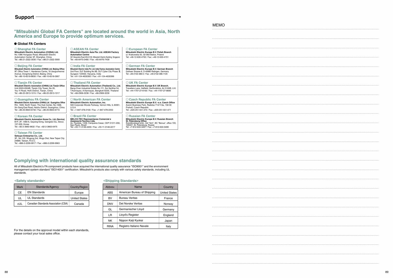
Support
MEMO
Complying with international quality assurance standardsAll of Mitsubishi Electric's FA component products have acquired the international quality assurance "ISO9001" and the environment management system standard "ISO14001" certification. Mitsubishi's products also comply with various safety standards, including UL standards.
Mark
CE
UL
cUL
EN Standards
UL Standards
Canadian Standards Association (CSA)
Standards/Agency Country/Region
Europe
United States
Canada
Abbrev.
ABS
BV
DNV
GL
LR
NK
RINA
American Bureau of Shipping
Bureau Veritas
Det Norske Veritas
Germanischer Lloyd
Lloyd's Register
Nippon Kaiji Kyokai
Registro Italiano Navale
Name Country
United States
France
Norway
Germany
England
Japan
Italy
"Mitsubishi Global FA Centers" are located around the world in Asia, North America and Europe to provide optimum services.
Global FA Centers
<Safety standards> <Shipping Standards>
For the details on the approval model within each standards, please contact your local sales office.
North American FA CenterMitsubishi Electric Automation, Inc.500 Corporate Woods Parkway, Vernon Hills, IL 60061, U.S.A.Tel: +1-847-478-2100 / Fax: +1-847-478-2253
ASEAN FA CenterMitsubishi Electric Asia Pte. Ltd. ASEAN Factory Automation Centre307 Alexandra Road #05-01/02, Mitsubishi Electric Building, SingaporeTel: +65-6470-2480 / Fax: +65-6476-7439
Russian FA CenterMitsubishi Electric Europe B.V. Russian BranchSt. Petersburg OfficeSverdlovskaya emb., bld "Sch", BC "Benua", office 720;195027, St. Petersburg, RussiaTel: +7-812-633-3497 / Fax: +7-812-633-3499
India FA CenterMitsubishi Electric India Pvt. Ltd. India Factory Automation Centre2nd Floor, DLF Building No.9B, DLF Cyber City Phase #, Gurgaon 122002, Haryana, IndiaTel: +91-124-4630300 / Fax: +91-124-4630399
Thailand FA CenterMitsubishi Electric Automation (Thailand) Co., Ltd.Bang-Chan Industrial Estate No.111, Soi Serithai 54, T.Kannayao, A.Kannayao, Bangkok10230, ThailandTel: +66-2906-3238 / Fax: +66-2906-3239
Czech Republic FA CenterMitsubishi Electric Europe B.V. -o.s. Czech OfficeAvenir Business Park, Radicka 714/113a, 158 00Praha5, Czech RepublicTel: +420-251-551-470 / Fax: +420-251-551-471
Taiwan FA CenterSetsuyo Enterprise Co., Ltd.3F., No.105, Wugong 3rd, Wugu Dist, New Taipei City 24889, Taiwan, R.O.C.Tel: +886-2-2299-9917 / Fax: +886-2-2299-9963
Guangzhou FA CenterMitsubishi Electric Automation (CHINA) Ltd. Guangzhou OfficeRm. 1609, North Tower, The Hub Center, No.1068, Xin Gang East Road, Haizhu District, Guangzhou, ChinaTel: +86-20-8923-6730 / Fax: +86-20-8923-6715
Korean FA CenterMitsubishi Electric Automation Korea Co., Ltd. (Service)B1F, 2F, 1480-6, Gayang-Dong, Gangseo-Gu, Seoul, 157-200, KoreaTel: +82-2-3660-9632 / Fax: +82-2-3663-0475
Shanghai FA CenterMitsubishi Electric Automation (CHINA) Ltd.No.1386 Hongqiao Road, Mitsubishi Electric Automation Center 3F, Shanghai, ChinaTel: +86-21-2322-3030 / Fax: +86-21-2322-3000
Tianjin FA CenterMitsubishi Electric Automation (CHINA) Ltd. Tianjin OfficeUnit 2003-2004B, Tianjin City Tower, No.35, You Yi Road, HeXi District, Tianjin, ChinaTel: +86-22-2813-1015 / Fax: +86-22-2813-1017
Beijing FA CenterMitsubishi Electric Automation (CHINA) Ltd. Beijing Office9F, Office Tower 1, Henderson Centre, 18 Jianguomennei Avenue, Dongcheng District, Beijing, ChinaTel: +86-10-6518-8830 / Fax: +86-10-6518-3907
Brazil FA CenterMELCO-TEC Representacao Comercial e Assessoria Tecnica Ltda.Av. Paulista, 1439, Cerqueira Cesar, CEP 01311-200, Sao Paulo, BrazilTel: +55-11-3146-2200 / Fax: +55-11-3146-2217
European FA CenterMitsubishi Electric Europe B.V. Polish Branchul. Krakowska 50, 32-083 Balice, PolandTel: +48-12-630-4700 / Fax: +48-12-630-4701
German FA CenterMitsubishi Electric Europe B.V. German BranchGothaer Strasse 8, D-40880 Ratingen, GermanyTel: +49-2102-486-0 / Fax: +49-2102-486-1120
UK FA CenterMitsubishi Electric Europe B.V. UK Branch.Travellers Lane, Hatfield, Hertfordshire, AL10 8XB, U.K.Tel: +44-1707-27-6100 / Fax: +44-1707-27-8695
88 89
MEMO MEMO
EC97J1234EC97J1113
Mitsubishi Electric Corporation Nagoya Works and Himeji Works are factories certified for ISO14001 (standards for environmental management systems) and ISO9001 (standards for quality assurance management systems).
90 91
Tailored solutions to meet your HMI and visualization needs
Mitsubishi Graphic Operation TerminalGOT1000 Series
Mitsubishi Graphic Operation Terminal
This catalog explains the typical features and functions of the GOT1000 series HMI and does not provide restrictions and other information on usage and module combinations. When using the products, always read the user's manuals of the products.Mitsubishi will not be held liable for damage caused by factors found not to be the cause of Mitsubishi; machine damage or lost profits caused by faults in the Mitsubishi products; damage, secondary damage, accident compensation caused by special factors unpredictable by Mitsubishi; damages to products other than Mitsubishi products; and to other duties.
• To use the products given in this catalog properly, always read the related manuals before starting to use them.
• The products within this catalog have been manufactured as general-purpose parts for general industries and have not been designed or manufactured to be incorporated into any devices or systems used in purpose related to human life.
• Before using any product for special purposes such as nuclear power, electric power, aerospace, medicine or passenger movement vehicles, consult with Mitsubishi.
• The products within this catalog have been manufactured under strict quality control. However, when installing the product where major accidents or losses could occur if the product fails, install appropriate backup or failsafe functions in the system.
L(NA)08054-H 1109(MDOC)New publication, effective Sep. 2011
Specifications subject to change without notice.
HEAD OFFICE: TOKYO BLDG., 2-7-3, MARUNOUCHI, CHIYODA-KU, TOKYO 100-8310, JAPANNAGOYA WORKS: 1-14, YADA-MINAMI 5, HIGASHI-KU, NAGOYA, JAPAN
Sales office
Mitsubishi Electric Automation Inc.500 Corporate Woods Parkway, Vernon Hills, IL 60061, U.S.A.
MELCO-TEC Representacao Comercial e Assessoria Tecnica Ltda. Av. Paulista, 1439, Cerqueira Cesar, CEP 01311-200, Sao Paulo, Brazil
Mitsubishi Electric Europe B.V. German BranchGothaer Strasse 8, D-40880 Ratingen, Germany
Mitsubishi Electric Europe B.V. UK Branch Travellers Lane, Hatfield, Hertfordshire, AL10 8XB, U.K.
Mitsubishi Electric Europe B.V. Italian Branch Viale Colleoni 7-20041 Agrate Brianza (Milano), Italy
Mitsubishi Electric Europe B.V. Spanish BranchCtra. de Rubí 76-80-AC.420, E-08190 Sant Cugat del Vallés (Barcelona), Spain
Mitsubishi Electric Europe B.V. French Branch25, Boulevard des Bouvets, F-92741 Nanterre Cedex, France
Mitsubishi Electric Europe B.V. -o.s. Czech OfficeAvenir Business Park, Radická 714/113a 158 00 Praha 5, Czech Republic
Mitsubishi Electric Europe B.V. Polish Branch ul. Krakowska 50, 32-083 Balice, Poland
Mitsubishi Electric Europe B.V. Russian Branch Moscow Office52, bld. 3, Kosmodamianskaya nab., RU-115054, Moscow, Russia
Circuit Breaker Industries Ltd.9 Derrick Road, Spartan, Gauteng PO Box 100, Kempton Park 1620, South Africa
Mitsubishi Electric Automation (China) Ltd.No.1386 Hongqiao Road, Mitsubishi Electric Automation Center, Shanghai, China
Setsuyo Enterprise Co., Ltd.6F., No.105, Wugong 3rd, Wugu Dist, New Taipei City 24889, Taiwan, R.O.C.
Mitsubishi Electric Automation Korea Co., Ltd.3F, 1480-6, Gayang-Dong, Gangseo-Gu, Seoul 157-200, Korea
Mitsubishi Electric Asia Pte, Ltd.307 Alexandra Road #05-01/02, Mitsubishi Electric Building, Singapore
Mitsubishi Electric Automation (Thailand) Co., Ltd.Bang-Chan Industrial Estate No.111 Soi Serithai 54,T.Kannayao, A.Kannayao, Bangkok 10230 Thailand
P.T. Autoteknindo Sumber MakmurMuara Karang Selatan, Block A / Utara No.1 Kav. No.11,Kawasan Industri Pergudangan, Jakarta- Utara 14440,P.O. Box 5045, Indonesia
Mitsubishi Electric India Pvt. Ltd.2nd Floor, DLF Building No.9B, DLF Cyber City Phase III, Gurgaon 122002, Haryana, India
Mitsubishi Electric Australia Pty. Ltd.348 Victoria Road, P.O. Box 11, Rydalmere, N.S.W. 2116, Australia
Country/Region
USA
Brazil
Germany
UK
Italy
Spain
France
Czech Republic
Poland
Russia
South Africa
China
Taiwan
Korea
Singapore
Thailand
Indonesia
India
Australia
Tel/Fax
Tel: +1-847-478-2100Fax: +1-847-478-2253
Tel: +55-11-3146-2200Fax: +55-11-3146-2217
Tel: +49-2102-486-0Fax: +49-2102-486-1120
Tel: +44-1707-27-6100Fax: +44-1707-27-8695
Tel: +39-039-60531 Fax: +39-039-6053-312
Tel: +34-935-65-3131Fax: +34-935-89-2948
Tel: +33-1-5568-5568Fax: +33-1-5568-5757
Tel: +420-251-551-470Fax: +420-251-551-471
Tel: +48-12-630-47-00Fax: +48-12-630-47-01
Tel: +7-495-721-2070Fax: +7-495-721-2071
Tel: +27-11-977-0770Fax: +27-11-977-0761
Tel: +86-21-2322-3030Fax: +86-21-2322-3000
Tel: +886-2-2299-2499Fax: +886-2-2299-2509
Tel: +82-2-3660-9530Fax: +82-2-3664-8372
Tel: +65-6470-2480Fax: +65-6476-7439
Tel: +66-2906-3238Fax: +66-2906-3239
Tel: +62-21-663-0833Fax: +62-21-663-0832
Tel: +91-124-4630300Fax: +91-124-4630399
Tel: +61-2-9684-7777Fax: +61-2-9684-7245
Compatible withWindows® 7


![Graphic Operation TerminalGOT1000 ... - Mitsubishi Electric · Mitsubishi iQ Platform-compatible Graphic Operation Terminal GOT1000 Series [GT12 Model] October 2009 New Product Release](https://img.dokumen.tips/doc/110x75/60bf38ae9c66c92e340a534e/graphic-operation-terminalgot1000-mitsubishi-electric-mitsubishi-iq-platform-compatible.jpg)