Embed Size (px)
Citation preview

2009/04/01© MAN Diesel
Global Greenship, September 2009Low Sulfur Fuel and Emissions Advances

2009/04/01© MAN Diesel 2
1. Singapore
5. South Korea, Busan
9. Germany, Hamburg
10. China, Qingdao
6. Netherl., Rotterdam
2. China, Shanghai
8. Taiwan, Kaohsiung
7. UAE, Dubai
3. China, Hong Kong
4. China, Shenzhen
existing ECAs: Baltic Sea, North Sea
planned ECAs: Coasts of USA, Hawaii and Canada
Top Container Ports :
discussed ECAs: Coasts of Mexico, Coasts of Alaska and Great Lakes, Singapore, Hong Kong, Korea, Australia, Black Sea, Mediterranean Sea (2014), Tokyo Bay (in 2015)
Most used trading routes
ECA and SECA Trends

2009/04/01© MAN Diesel
Proposed North American Emission Control Area

2009/04/01© MAN Diesel
Local SECA – CARB, 2009
�CARB Regulations for California, starting July 2009:
ZONE –
� 24 miles from coastal California
� Regulation -
� July 1, 2009 – maximum 0.5% sulfur
� January 1, 2012 – maximum 0.1% sulfur

2009/04/01© MAN Diesel
IMO & CARB Fuel-Sulphur Content Limits

2009/04/01© MAN Diesel
Low-sulphur Fuel Operation
Engine
Compatibilityof mixed fuels
Tank systemconsiderations
Viscosity
OilCylinder Oil BN40-70
Fuel changeover requirementHigh S% Low S%

2009/04/01© MAN Diesel 2009.02.25 (LD/MZP)
ViscosityThe engine fuel pump is designed for high viscosity, heavy fuel operation. Low viscosity fuels can cause excessive wear, and affect injection pressure, particularly during start, low load and low rpm.
In worn pumps, if viscosity is too low, internal leakage can increase and starting the engine will be difficult because of lack of injection pressure.
LubricityThe refinery process to remove sulfur also impacts lubricity, which could result in fuel pump seizures. While refiners add lubricity additives, MAN Diesel recommends that, prior to using distillates fuels with less than 0.05% sulphur, lubricity be tested.
Low Sulphur Fuels / Viscosity and Lubricity

2009/04/01© MAN Diesel
� Many factors influence viscosity tolerance during start and low load operation:
� Engine condition and maintenance
� Fuel pump wear
� Engine adjustment
� Temperatures in the fuel system
� Human factors
Factors influencing viscosity tolerance

2009/04/01© MAN Diesel
Poor Fuel Switching Techniques
Source: Gard
2009/04/01© MAN Diesel
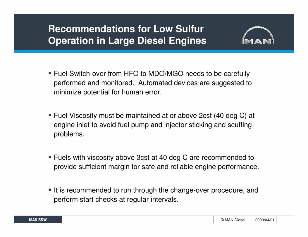
Recommendations for Low Sulfur Operation in Large Diesel Engines
� Fuel Switch-over from HFO to MDO/MGO needs to be carefully performed and monitored. Automated devices are suggested to minimize potential for human error.
� Fuel Viscosity must be maintained at or above 2cst (40 deg C) atengine inlet to avoid fuel pump and injector sticking and scuffing problems.
� Fuels with viscosity above 3cst at 40 deg C are recommended to provide sufficient margin for safe and reliable engine performance.
� It is recommended to run through the change-over procedure, and perform start checks at regular intervals.

2009/04/01© MAN Diesel 2009.02.25
•
Low Sulphur / Viscosity fuels
0
20
40
60
80
100
120
140
1 2 3 4 5 6 7 8
Fuel
Tem
p (d
eg C
)
Fuel Viscosity (cSt) @ 40C
Fuel Temperature vs Viscosity
2.0 cSt
4.0 cSt
5.0 cSt
1.5 cSt
GOODFuel above 3 cSt
MAN Diesel recommend to operate the engine on fuels with viscosities above 3 cSt
DOUBTFULFuel viscosity 2 - 3 cSt
MAN Diesel strongly recommend to make start checks prior to port operation
3.0 cSt
NOT GOODFuel below 2cSt
MAN Diesel do not recommend to operate the engine on fuels with viscosities lower than 2 cSt
The horizontal axis shows the bunkered fuel viscosity in cSt at 40 deg C, which should be informed in the bunker analysis report.If the temperature of the MGO is below the red curve at engine inlet, the viscosity is above 2 cSt.
Example: MGO with viscosity of 3 cSt at 40 deg C must have a temperature below 63 deg C at engine inlet to ensure a viscosity above 2 cSt. Example: MGO with a viscosity of 5 cSt at 40 deg C is entering the engine at 50 deg C. The green curves show that the fuel enters ,the engine at approximately 4.0 cSt.Example: MGO with a viscosity of 1.5 cSt at 40 deg C needs cooling t o 22 deg C to reach 2 cSt.

2009/04/01© MAN Diesel
Viscosities of Marine Distillate Fuels
Characteristic Unit Limit DMX DMA DMB DMC
Density at 15°C kg/m³ max. - 890.0 900.0 920.0
Viscosity at 40°C mm²/s min. 1.40 1.50 - -
Viscosity at 40°C mm²/s max. 5.50 6.00 11.0 14.0
Flash point °C min. - 60 60 60
Sulphur %(m/m) max. 1.00 1.50 2.00 2.00
Marine Distillate Fuels
(LEE4/KID)

2009/04/01© MAN Diesel
Auxiliary SystemDiesel Oil Cooler in Fuel Oil System
In order to ensure a satisfactory hydrodynamic film between fuel pump plunger and barrel MAN Diesel requires a minimum viscosity of 2 cSt of diesel oil at inlet to engine .
Viscosity at 40°C
Temperature to obtain Viscosity of 2 cSt
Temperature to obtain Viscosity of 3 cSt
DMX 1.4 cSt 17.4°C -3.0°C
DMA 1.5 cSt 21.9°C 1.2°C
(LEE4/KID)
Limit for Viscosity at Inlet to Engine

2009/04/01© MAN Diesel
Methods to deal with Low Sulfur fuel operation
�Fuel Coolers or Chillers
�Diesel Switch

2009/04/01© MAN Diesel
HFO system with MDO cooler

2009/04/01© MAN Diesel
Auxiliary SystemDiesel Oil Chiller in Fuel Oil System
(LEE4/KID)

2009/04/01© MAN Diesel
DIESELswitch „S“

2009/04/01© MAN Diesel
DIESELswitch Retrofit
Retrofit Solution:

2009/04/01© MAN Diesel
DIESELswitch
� Safely controlled change-over process
Minimized risk of damaged fuel injection parts due to abrupt temperature changes
The system will stop the change over process if the temperature increase/ decrease is too fast, and will give an alarm signal and freeze the actual position
� Change over running at full load possibleNo need to run engine with lowest power for change over process

2009/04/01© MAN Diesel
DIESELswitch
� Displays status of change over
� Displays remaining change over time
� Able to run the change over process manually or stop the process at any point
� Remote operation possible by second touch screen

2009/04/01© MAN Diesel
Advances in Emission Control.
�Methods of achieving upcoming Tier 2 and Tier 3 emissions regulations.

2009/04/01© MAN Diesel 22
Tier 2 and Tier 3 Proposal
NOX reduction in a 2-step approach:
� Tier II - from 2011 achieved by in-engine measures – 15-25% reduction� Tier III - from 2016 using special NOX reduction methods – 80% reduction
from Tier I (only in defined Emission Control Areas (ECAs)).
� Other Emissions Regulation Potentials -
� Requirement to retrofit older vessels (pre Annex VI) initially back to 2000, and potentially back to early 1980’s.
� For older vessels - “20% baseline reduction + hardware changes known to positively influence emission characteristics”.

2009/04/01© MAN Diesel 23
Proposed NOX Limits
3335627
NO
X(g
/kW
h)

2009/04/01© MAN Diesel 24
History and Future for SFOC and NOx
3334808.2007.04.10 (LSP/LB)
Year
SFOC g/kWh
Ideal Carnot cycle
Full-ratedDe-rated
84VT2BF180K98FF
KGF
GB/GBEGFCA
MC/MC-C
NOx
NOx g/kWh
SFOC
0
50
100
150
200
250
1940 1960 1980 2000 2020
10
20
ME/ME-C
2007
?

2009/04/01© MAN Diesel
Operators Demand Fuel Savings
253336254.2008.12.16 LSP/GT

2009/04/01© MAN Diesel 26
Compliance with Expected IMO/EPA C3 Regulation – 2 Stroke engines
IMO Regulation Reduction method
Tier 1 Current IMO Regulation• NOx speed limit curve
• Fuel nozzle & performance optimization
• From 3 to 5% SFOC tolerance
Tier 2 • 15 to 25% NOx reduction (from Tier 1) • PM & SOx reduction by fuel Sulfur
content
• Fuel nozzle & performance optimization
• Slide valves mandatory
• CO2 & SFOC penalty 1-3%
Tier 3 • Up to 80% NOx reduction (from Tier 1)From Jan. 2016
• EGR, SAM, SCR
• CO2 & SFOC penalty

2009/04/01© MAN Diesel 27
Emission Control – Effect and Cost
Reduction capability First costin % of
engine price
Running cost index
Tier 1 = 100NOx CO HC PM
Primary methods
Engine adjustments 10-15% ���� ���� ���� 0%/Small 102
SL & Alpha lube - - ���� ���� 0%/Small 101
Water emulsion 20-30% - - ���� 10-20% *) 101
SAM 40-50% ���� ���� ���� 20-30% *) 101
Secondary methods
SCR (Sel. Cat. Reduction) 80-98% ? ? ? 50-70% 110
*) Depending on installation

2009/04/01© MAN Diesel
EGR WIF
32
1
5
6
78
4
SCR
Tier 3 Technologies

2009/04/01© MAN Diesel
10K98MC-C and 6S35MC on the same Testbed
L/74236-1.0/0402 (3000/OG)

2009/04/01© MAN Diesel 30
“Slide Valve” Fuel Injection Nozzles

2009/04/01© MAN Diesel 31
7S50ME-C – 75% LoadMode Change Demonstration
L/74496-0.1/0903 (2430/NK)
0
100
200
300
400
500
600
700
800
900
1000
1100
1200
1300
16:37 16:38 16:39 16:40 16:41 16:42 16:43 16:44 16:45 16:46
NO
x[p
pm]
2003-02-17
140 150 160 170 180 190 200 210 220 2300 0
20 100
40 200
60 300
80 400
100 500
120 600
140 700
160 800
CylinderPump
2003-02-17
140 150 160 170 180 190 200 210 220 2300 0
20 100
40 200
60 300
80 400
100 500
120 600
140 700
160 800
CylinderPump
Economy mode Low NOX mode
Time
2009/04/01© MAN Diesel 323331562.2006.11.22 (3001/LB)
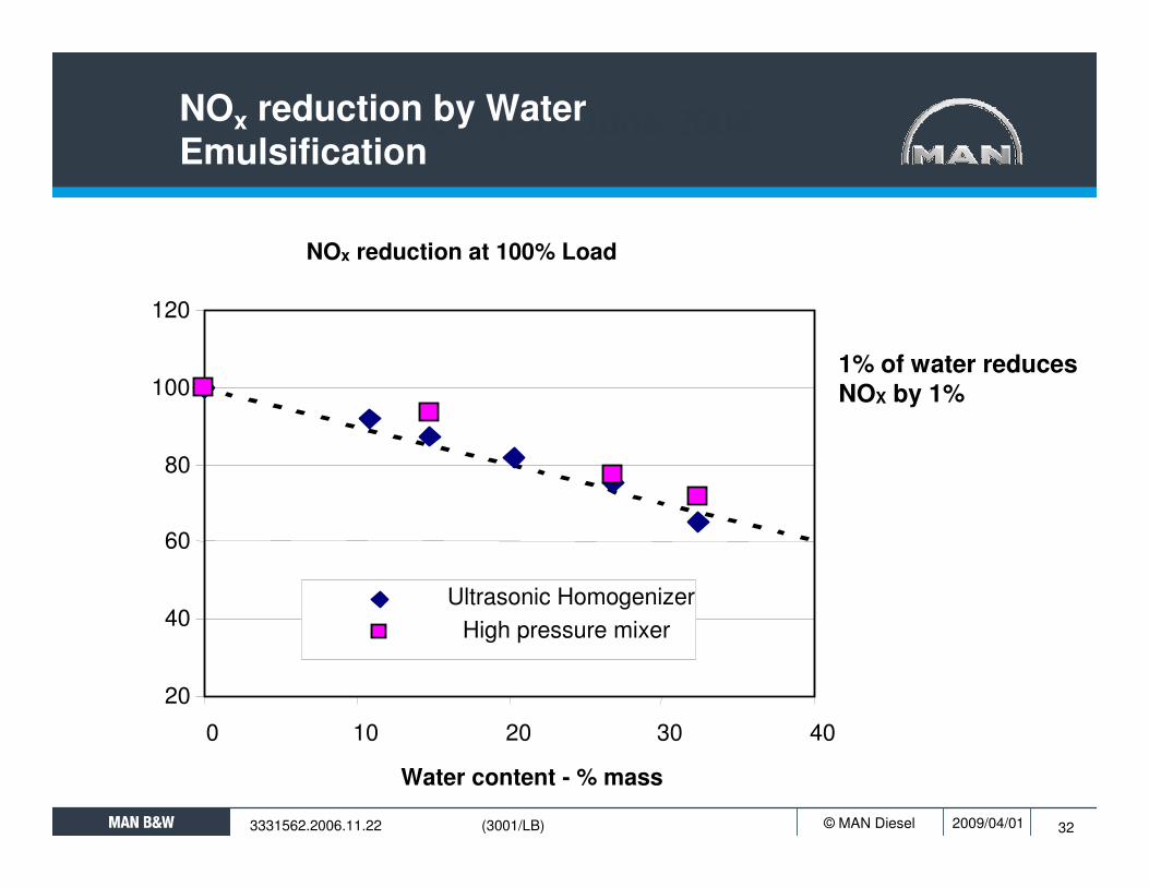
CIMAC Kyoto June 2004
NOx reduction at 100% Load
20
40
60
80
100
120
0 10 20 30 40
Water content - % mass
Ultrasonic HomogenizerHigh pressure mixer
NOx reduction by Water Emulsification
1% of water reducesNOX by 1%

2009/04/01© MAN Diesel 33
SCR System
L/71835-9.0/0801 (2160/PZS)
32
1
5
6
78
4Deck
1 SCR reactor2 Turbocharger bypass3 Temperature sensor after SCR4 Large motors for
auxiliary blowers5 Urea injector6 SCR bypass7 Temperature sensor
before SCR8 Additional flange in exhaust
gas receiver9) Best suited for steady high-load conditions with limited use of HFO
C

2009/04/01© MAN Diesel 34
Scavenge Air Moisturing (SAM)
L/73394-7.0/0902 (2430/NK)
HAMunit High heat capacity and low O2 in scavenge air give low combustion temperatures
Humidification/moisturing of scavenge air increases heat capacity and lower the O2content
Low combustion temperatures give low NOx
SAM influence on NOx formation
Influence on reliability and safety: Field test

2009/04/01© MAN Diesel 35
Water Stages on SAM System
3333238.2005.11.09 (2432/PZS)
Sea Water Inlet
Sea Water Outlet
FW Stage1 InletFW Stage1 Outlet
FW Stage2 Inlet
FW Stage2 Outlet

2009/04/01© MAN Diesel
EGR – Exhaust Gas Recirculation

2009/04/01© MAN Diesel
EGR – Exhaust Gas Recirculation
3335239.2007.11.12 (LDF/NK)
NOx Crossover eq. to -20% per 1g/kWh
NOx/SFOC crossover
-60
-40
-20
0
20
40
60
80
100
120
0 10 20 30
EGR (%)
Rel
etiv
e N
Ox
in %
0
1
2
3
4
5
6
7
8
9
Rel
ativ
e S
FOC
in g
/kW
hNOx
SFOC

2009/04/01© MAN Diesel
MAN Diesel EGR Unit for MAN B&W Low Speed Engines
Exhaust gas into EGR scrubber from exhaust gas receiver
Exhaust gas out of EGR scrubber, into EGR cooler
Cooling sea water to/from EGR cooler
Exhaust gas out of EGR blower, into charge air pipe
EGR Scrubber
EGR Cooler
EGR Blower

2009/04/01© MAN Diesel 39
Thank you for your Attention
3334660.2007.01.05 (3000/OG