Embed Size (px)
Citation preview

Global Call E-1/T-1 CAS/R2Technology User's Guide
for Linux and Windows
Copyright © 2003 Intel Corporation
05-0615-010

INFORMATION IN THIS DOCUMENT IS PROVIDED IN CONNECTION WITH INTEL®PRODUCTS. NO LICENSE, EXPRESS OR IMPLIED, BY ESTOPPEL OR OTHERWISE, TO ANYINTELLECTUAL PROPERTY RIGHTS IS GRANTED BY THIS DOCUMENT. EXCEPT ASPROVIDED IN INTEL'S TERMS AND CONDITIONS OF SALE FOR SUCH PRODUCTS, INTELASSUMES NO LIABILITY WHATSOEVER, AND INTEL DISCLAIMS ANY EXPRESS ORIMPLIED WARRANTY, RELATING TO SALE AND/OR USE OF INTEL PRODUCTSINCLUDING LIABILITY OR WARRANTIES RELATING TO FITNESS FOR A PARTICULARPURPOSE, MERCHANTABILITY, OR INFRINGEMENT OF ANY PATENT, COPYRIGHT OROTHER INTELLECTUAL PROPERTY RIGHT. Intel products are not intended for use in medical,life saving, or life sustaining applications.Intel may make changes to specifications and product descriptions at any time, without notice.This document as well as the software described in it is furnished under license and may only be usedor copied in accordance with the terms of the license. The information in this manual is furnished forinformational use only, is subject to change without notice, and should not be construed as acommitment by Intel Corporation. Intel Corporation assumes no responsibility or liability for anyerrors or inaccuracies that may appear in this document or any software that may be provided inassociation with this document.Except as permitted by such license, no part of this document may be reproduced, stored in a retrievalsystem, or transmitted in any form or by any means without express written consent of IntelCorporation.Copyright © 2003 Intel Corporation. All Rights Reserved.AlertVIEW, AnyPoint, AppChoice, BoardWatch, BunnyPeople, CablePort, Celeron, Chips, CTMedia, Dialogic, DM3, EtherExpress, ETOX, FlashFile, i386, i486, i960, iCOMP, InstantIP, Intel,Intel logo, Intel386, Intel486, Intel740, IntelDX2, IntelDX4, IntelSX2, Intel Create&Share, IntelGigaBlade, Intel InBusiness, Intel Inside, Intel Inside logo, Intel NetBurst, Intel NetMerge, IntelNetStructure, Intel Play, Intel Play logo, Intel SingleDriver, Intel SpeedStep, Intel StrataFlash, IntelTeamStation, Intel Xeon, Intel XScale, IPLink, Itanium, LANDesk, LanRover, MCS, MMX, MMXlogo, Optimizer logo, OverDrive, Paragon, PC Dads, PC Parents, PDCharm, Pentium, Pentium IIXeon, Pentium III Xeon, Performance at Your Command, RemoteExpress, Shiva, SmartDie,Solutions960, Sound Mark, StorageExpress, The Computer Inside., The Journey Inside,TokenExpress, Trillium, VoiceBrick, Vtune, and Xircom are trademarks or registered trademarks ofIntel Corporation or its subsidiaries in the United States and other countries.* Other names and brands may be claimed as the property of others.Publication Date: February 2003Document Number: 05-0615-010Intel Converged Communications, Inc.1515 Route 10Parsippany, NJ 07054For Technical Support, visit the Intel Telecom Support Resources website at:http://developer.intel.com/design/telecom/support/For Products and Services Information, visit the Intel Communications Systems Products websiteat: http://www.intel.com/network/csp/For Sales Offices and other contact information, visit the Intel Telecom Building Blocks SalesOffices page at: http://www.intel.com/network/csp/sales/

iii
Table of Contents1. How to Use This Guide ................................................................................... 11.1. Organization of this Guide ............................................................................. 11.2. Intel® Dialogic® Products That Support E-1/T-1 Signaling ......................... 21.3. Related Information........................................................................................ 22. Signaling Concepts .......................................................................................... 52.1. Making Telephone Calls: Transmission of Digits and Signaling
Information .................................................................................................... 52.1.1. Making Long Distance and Global Telephone Calls ............................. 7
2.2. T-1 Robbed Bit Signaling Concepts ............................................................... 82.3. E-1 CAS Signaling Concepts ......................................................................... 92.4. R2 MF Signaling Concepts .......................................................................... 10
2.4.1. R2 MF Multifrequency Combinations................................................. 122.4.2. R2 MF Signal Meanings...................................................................... 122.4.3. R2 MF Compelled Signaling ............................................................... 14
2.5. Direct Dialing In (DDI) Service ................................................................... 153. Developing Global Call E-1 CAS or T-1 Robbed Bit Applications ........... 173.1. Global Tone Detection (GTD) Tone Considerations ................................... 173.2. Call Progress and Call Analysis ................................................................... 19
3.2.1. Call Analysis with DM3 Boards .......................................................... 193.2.2. Call Analysis with Springware Boards ................................................ 233.2.3. Call Analysis Functionality for PDK Protocols ................................... 243.2.4. Call Analysis Functionality for ICAPI Protocols................................. 31
3.3. Header Files ................................................................................................. 333.4. Resource Association ................................................................................... 343.5. Alarm Handling............................................................................................ 35
3.5.1. Alarm Handling for DM3 boards......................................................... 353.5.2. Alarm Handling for Springware Boards .............................................. 37
3.6. Run Time Configuration of the PDKRT Call Control Library ..................... 393.7. Run Time Configuration of PDK Protocol Parameters ................................ 413.8. Determining the Protocol Version ................................................................ 444. Applying Global Call Functions to E-1 CAS or T-1 Robbed Bit
Applications................................................................................................ 474.1. gc_AcceptCall( ) .......................................................................................... 474.2. gc_AnswerCall( ) ......................................................................................... 484.3. gc_BlindTransfer( ) ...................................................................................... 48

Global Call E-1/T-1 CAS/R2 Technology User's Guide for Linux and Windows
iv
4.4. gc_CallAck( ) ............................................................................................... 484.5. gc_Close( ) ................................................................................................... 494.6. gc_CompleteTransfer( ) ............................................................................... 494.7. gc_Detach( ) ................................................................................................. 494.8. gc_DropCall( ) ............................................................................................. 504.9. gc_Extension( ) ............................................................................................ 514.10. gc_GetCallInfo( ) ....................................................................................... 524.11. gc_GetParm( ) ............................................................................................ 534.12. gc_HoldCall( )............................................................................................ 544.13. gc_MakeCall( )........................................................................................... 54
4.13.1. PDK_MAKECALL_BLK ................................................................. 564.13.2. IC_MAKECALL_BLK ..................................................................... 57
4.14. gc_OpenEx( ) ............................................................................................ 584.14.1. Conventions for Specifying the devicename Parameter..................... 584.14.2. Examples of the devicename Parameter ............................................ 594.14.3. Other gc_OpenEx( ) Considerations.................................................. 60
4.15. gc_ResetLineDev( ).................................................................................... 614.16. gc_RetrieveCall( ) ...................................................................................... 614.17. gc_SetBilling( ) .......................................................................................... 614.18. gc_SetChanState( ) ..................................................................................... 624.19. gc_SetEvtMsk( )......................................................................................... 624.20. gc_SetParm( )............................................................................................. 624.21. gc_SetUpTransfer( )................................................................................... 634.22. gc_Start( ) and gc_Stop( ) .......................................................................... 644.23. gc_StartTrace( ).......................................................................................... 644.24. gc_SwapHold( ) ......................................................................................... 645. Resource Allocation and Routing ................................................................ 675.1. Dedicated Voice Resources .......................................................................... 67
5.1.1. Dedicated Voice Resources Example .................................................. 695.2. Shared Voice Resources ............................................................................... 70
5.2.1. Shared Voice Resources Example ....................................................... 716. Protocols......................................................................................................... 736.1. Protocols Supported ..................................................................................... 736.2. Protocol File Naming Conventions .............................................................. 746.3. Protocol Components ................................................................................... 76
6.3.1. Protocol Modules ................................................................................ 766.3.2. Country Dependent Parameter (.cdp) Files.......................................... 776.3.3. Parameter (.prm) Files (Springware only) ........................................... 77

Table of Contents
v
7. Debugging Applications ................................................................................ 817.1. Debugging Applications that Use PDK Protocols ........................................ 81
7.1.1. Enabling and Disabling the Logging ................................................... 827.1.2. Populating and Using a CCLIB_START_STRUCT ........................... 827.1.3. Defining the GC_PDK_START_LOG Environment Variable ............ 89
7.2. Debugging Applications that Use ICAPI Protocols ..................................... 89Index.................................................................................................................... 93

Global Call E-1/T-1 CAS/R2 Technology User's Guide for Linux and Windows
vi

vii
List of TablesTable 1. Signaling Used to Dial (Hz) .................................................................... 6Table 2. Global Call Call Progress Settings ........................................................ 20Table 3. Call Analysis Support on DM3 Boards with CAS ................................ 21Table 4. TONE_t Signal Definition Parameters .................................................. 28Table 5. Configurable PDKRT Call Control Library Parameters........................ 40Table 6. PSL and SYS Parameters ...................................................................... 41Table 7. Configurable PDK Protocol Parameters................................................ 42Table 8. PDK_MAKECALL_BLK Field Descriptions....................................... 57Table 9. IC_MAKECALL_BLK Field Descriptions........................................... 58Table 10. Parameters Supported, gc_GetParm( ) and gc_SetParm( ).................. 63Table 11. Protocol File Naming Conventions ..................................................... 74Table 12. Sample ICAPI Protocol File Set.......................................................... 75Table 13. Sample PDK Protocol File Set ............................................................ 76Table 14. cclib_data Fields and Values ............................................................... 83Table 15. Loglevel Parameter Values ................................................................. 85Table 16. Service Parameter Values.................................................................... 86Table 17. Cachedump Parameter Values............................................................. 87Table 18. Sample Channel Parameter Values...................................................... 88Table 19. icapi.cfg File Parameters ..................................................................... 90

Global Call E-1/T-1 CAS/R2 Technology User's Guide for Linux and Windows
viii

1
1. How to Use This GuideThis guide is for users who use the Global Call application programming interface(API), the Global Call Protocol Development Kit Run Time (PDKRT) call controllibrary, or the Global Call Interface Control API (ICAPI) call control library andrelated software to develop Linux or Windows applications in an E-1 channelassociated signaling (CAS) or T-1 robbed bit environment.
Complete reference information and programming guidelines for the Global CallAPI are given in the companion documents, Global Call API Library Referenceand Global Call API Programming Guide . Certain Global Call functions haveadditional functionality or perform differently when used in an E-1 CAS or T-1robbed bit environment. The general function descriptions in the Global Call APILibrary Reference do not contain detailed information on a particular technology.Detailed information in terms of the additional functionality or the difference inperformance of those functions in an E-1 CAS or T-1 robbed bit environment iscontained in this Global Call E-1/T-1 CAS/R2 Technology User's Guide .
NOTE: Differences between the implementation of a Global Call application in aLinux or a Windows environment are either described parenthetically orare presented in separate paragraphs or sections. Information that isspecific to the use of DM3 or Springware boards is identified explicitly.Information that is specific to the use of the PDKRT or ICAPI callcontrol library is identified explicitly. Information about PDK protocolsis applicable to DM3 and Springware boards unless otherwise noted.Information about ICAPI protocols is applicable to Springware boardsonly.
The rest of this chapter describes the organization of this guide, the productscovered by this guide, and related publications.
1.1. Organization of this Guide
The information in this guide is organized as follows:
Chapter 2. Signaling Concepts provides an overview of E-1 CAS and T-1 robbedbit signaling concepts.

Global Call E-1/T-1 CAS/R2 Technology User's Guide for Linux and Windows
2
Chapter 3. Developing Global Call E-1 CAS or T-1 Robbed Bit Applicationspresents guidelines for developing E-1 CAS or T-1 robbed bit applications.
Chapter 4. Applying Global Call Functions to E-1 CAS or T-1 Robbed BitApplications describes the additional functionality or the difference inperformance of specific Global Call functions when used in an E-1 CAS or T-1robbed bit environment.
Chapter 5. Resource Allocation and Routing describes using dedicated or sharedvoice resources in an E-1 CAS or T-1 robbed bit environment.
Chapter 6. Protocols describes the protocol conventions used and programmingconsiderations when incorporating individual country protocol(s) into yourapplication.
Chapter 7. Debugging Applications describes the diagnostic tools available fordebugging a Global Call application.
1.2. Intel® Dialogic® Products That Support E-1/T-1Signaling
The Global Call software provides a consistent interface across Intel® Dialogic®products interfaced to various networks (for example, E-1 CAS, T-1 robbed bit,E-1 ISDN, T-1 ISDN, analog, SS7, and IP). See the Release Guide for yourIntel® Dialogic® system release for the Intel® Dialogic® product combinationsthat provide E-1 CAS signaling and T-1 robbed bit signaling capabilities.
1.3. Related Information
Use this guide in conjunction with the following manuals:
• Global Call API Library Reference � provides a reference to all functions,events, data structures, and error codes in the Global Call API library.
• Global Call API Programming Guide � provides guidelines for developingapplications using the Global Call API.

1. How to Use This Guide
3
• Global Call Country Dependent Parameters (CDP) Reference � describes theparameters associated with each of the countries needed for utilizing GlobalCall.
• Release Notes for the Global Call Protocols package � provides informationabout installing and using Global Call protocols, including how to configureDM3 boards to run PDK protocols.
The following information is also useful:
• Release Guide for your system release � provides information about thesystem release, system requirements, software and hardware features,supported hardware, and release documentation.
• Release Update for your system release (available on the Technical SupportWeb site only) � describes compatibility issues, restrictions and limitations,known problems, and late-breaking updates or corrections to the releasedocumentation. The Release Update is updated with new information asneeded curing the lifecycle of the release.
• http://developer.intel.com/design/telecom/support/ � Technical Support Website which contains developer support information, downloads, releasedocumentation, technical notes, application notes, a user discussion forum,and more.
For additional information about E-1 or T-1 telephony, see the followingpublications:
• R2 MF Signaling References
• Specifications of Signaling Systems R1 and R2 , International Telegraphand Telephone Consultative Committee (CCITT), Blue Book Vol. VI,Fascicle VI.4, ISBN 92-61-03481-0
• General Recommendations on Telephone Switching and Signaling ,International Telegraph and Telephone Consultative Committee(CCITT), Blue Book Vol. VI, Fascicle VI.1, ISBN 92-61-03451-9
• T-1 Robbed Bit Signaling References
• Bellamy, John, Digital Telephony, 2nd ed. New York: John Wiley &Sons, 1991
Global Call E-1/T-1 CAS/R2 Technology User's Guide for Linux and Windows
4
• Fike, John L., and George Friend, Understanding Telephone Electronics ,Indiana: Howard W. Sams & Company, 1988
• Flanagan, William A., The Guide to T-1 Networking, 4th ed. New York,Telecom Library Inc., 1990
• LATA Switching Systems Generic Requirements (LSSGR) , BellcoreTechnical Reference TR-TSY-000064, Issue 2, July 1987, and modules,Bellcore

5
2. Signaling ConceptsThis chapter provides an overview of how digits and signaling information aretransmitted when a telephone call is made, and describes the T-1 robbed bit, E-1CAS, R2 MF, and Direct Dialing In (DDI) signaling concepts.
2.1. Making Telephone Calls: Transmission of Digits andSignaling Information
Historically, making a telephone call started with taking your telephone handsetout of its cradle. This action caused your telephone to go off-hook. For analogtelephones, going off-hook closes a circuit (called the local loop) connected to thelocal Central Office (CO) and causes a loop current to flow through the local loopcircuit created.
The CO reacts by generating dial tone (typically, a combination of 350 Hz and440 Hz tones), which indicates that you can dial. Traditionally, you would dialyour number using pulse dialing (also called rotary dialing). Pulse dialing sendsdigit information to the CO by momentarily opening and closing (or breaking) thelocal loop from the calling party to the CO. This local loop is broken once for thedigit 1, twice for 2, etc., and 10 times for the digit 0. As each number is dialed, theloop current is switched on and off, resulting in a number of pulses being sent toyour local CO.
Alternatively, you may dial a number using tone dialing, wherein sounds representthe digits dialed (0 through 9, # and * are dialing digits). Each digit is assigned aunique pair of frequencies called Dual Tone Multi Frequency (DTMF) digits (seeTable 1. Signaling Used to Dial). Although DTMF signaling is designed foroperation on international networks with 15 multifrequency combinations in eachdirection, in national networks it can be used with a reduced number of signalingfrequencies (for example, 10 multifrequency combinations).
In addition to the DTMF digit standard, telcos also use a Multi Frequency (MF)digit standard (see Table 1. Signaling Used to Dial). MF digits are typically usedfor CO-to-CO signaling. The MF digit standard is similar to the DTMF digitstandard except that different pairs of frequencies are assigned. Some MF digitsuse approximately the same frequencies as DTMF digits; for example, the digit 4

Global Call E-1/T-1 CAS/R2 Technology User's Guide for Linux and Windows
6
uses 770 and 1209 Hz for DTMF transmissions or 700 and 1300 Hz for MFtransmissions. Because of this frequency overlap, MF digits could be mistaken forDTMF digits if the incorrect tone detection is enabled. The accuracy of digitdetection depends on:
• the digit sent
• the type of detection, MF or DTMF, enabled when the digit is detected. Seethe Voice API Library Reference for your operating system for details.
Table 1. Signaling Used to Dial (Hz)
Code Pulse DTMF MF R2 MFForward
R2 MFBackward
1 1 697, 1209 700, 900 1380, 1500 1140, 1020
2 2 697, 1336 700, 1100 1380, 1620 1140, 900
3 3 697, 1477 900, 1100 1500, 1620 1020, 900
4 4 770, 1209 700, 1300 1380, 1740 1140, 780
5 5 770, 1336 900, 1300 1500, 1740 1020, 780
6 6 770, 1477 1100, 1300 1620, 1740 900, 780
7 7 852, 1209 700, 1500 1380, 1860 1140, 660
8 8 852, 1336 900, 1500 1500, 1860 1020, 660
9 9 852, 1477 1100, 1500 1620, 1860 900, 660
0 10 941, 1336 1300, 1500 1740, 1860 780, 660
* - 941, 1209 1100, 1700 1380, 1980 1140, 540
# - 941, 1477 1500, 1700 1500, 1980 1020, 540
For each call, signaling information (off-hook, number dialed) must be detectedby the local CO and then sent to each successive CO until the destination CO isreached. The destination CO attempts to connect to the called party. Concurrently,the destination CO sends back signaling information (such as line busy, networkbusy signals, etc.) representing the condition or status of the called party�s line.

2. Signaling Concepts
7
This signaling information passes through the network as audio tones or assignaling bits. The number of tones used and the frequency combinations used toconvey this signaling information vary from country to country and from telco totelco. In addition, private networks may combine various signaling techniques.
After dialing, you listen to hear the progress and status of the call:
• Ringing tones (ringback) indicate that ring voltage has been applied to thecalled party�s line.
• A busy tone is heard when the called party�s telephone is off-hook.
• A fast busy tone may be heard if the telephone network is busy.
• An operator intercept signal is heard if an invalid number is dialed. Theoperator intercept signal is three rising tones followed by a recording.
NOTE: No ringing tones are heard when connected to some telcos.
The CO typically indicates the progress of making a call by generating thesevarious tones. When making long distance calls, the telco may make brief drops inloop current to indicate:
• an acknowledgment that the distant CO was reached
• that the calling party�s line went off-hook
After a call is connected, a telco service may be requested by a flash-hook. Aflash-hook puts the telephone on-hook briefly, long enough for the CO to detectthe flash-hook, but not long enough to cause a disconnect. A flash-hook maysignal a request for a second dial tone to allow 3-way conferencing or to transferthe call.
At the completion of the call, one or both parties hang up the telephone. Typically,the CO sends a disconnect signal. However, some telcos don�t send a disconnectsignal; therefore a local CO must use other methods to detect a remote disconnect.
2.1.1. Making Long Distance and Global Telephone Calls
Long distance calls may involve transmitting dialing and other signalinginformation from the local CO, through several intermediate COs, to the distantcalled party�s CO and then connecting to the called party. A mixture of signaling
Global Call E-1/T-1 CAS/R2 Technology User's Guide for Linux and Windows
8
systems and protocols may be encountered especially when making global calls.Local call signaling must be translated into signaling that may pass over analoglines, T-1 digital trunks, E-1 digital trunks, optical fiber, satellite links, etc. Allsignaling sent over digital trunks must be converted to bits that can be transmittedor multiplexed with the digitized voice transmissions.
Each telco, country, or region tends to apply different signaling standards thatmust be observed to ensure that a call gets switched through to the called party.For example, some telcos may encode E&M (Ear and Mouth) signals onto thevoice path using a single frequency (SF) tone. When present, this tone indicates anon-hook condition. Otherwise, the line is considered to be off-hook (absence oftone). Typically, when the same manufacturer�s product is connected to both endsof a digital trunk, then the signaling technique used is transparent as long as allsignaling is handled.
2.2. T-1 Robbed Bit Signaling Concepts
A T-1 trunk operates at 1.544 Mbps divided into 24 time slots with each time slotoperating at 64 kbps [digital signal level 1 (DS-1) rate]. A single 8-bit samplefrom each of 24 voice channels comprises a D4 frame of 24 time slots on a T-1trunk. Twelve D4 frames make up a D4 superframe.
Signaling information is carried on a T-1 trunk by two signaling bits, an A-bit anda B-bit. Each time slot in the sixth frame of a D4 superframe has the leastsignificant bit replaced with A-bit signaling information. Likewise, each time slotin the twelfth frame of the D4 superframe has the least significant bit replacedwith B-bit signaling information. This method of replacing the least significant bitwith signaling information is called robbed bit signaling. Thus, a T-1 robbed bittrunk carries all signaling within the voice time slot (channel) itself.
Dialing, if not done using DTMF or MF tones, is accomplished by alternating theA and B signaling bits between 0 and 1 to mimic rotary dial pulses. Signaling bitsrepresent the state of the M lead on the E&M interface of the calling party. Whenthe called party answers, the M lead returns continuous 1s. When a party hangsup, their signal bits revert to 0s to indicate on-hook. Some telcos invert thesesignaling bits so that 0 = off-hook and 1 = on-hook.

2. Signaling Concepts
9
New telco services may require the use of more than the four signaling statesprovided by the A and B bits. An extended superframe (ESF) adopted by AT&Tprovides two additional signaling bits, the C-bit in frame 18 and the D-bit in frame24.
2.3. E-1 CAS Signaling Concepts
An E-1 digital trunk operates at 2.048 Mbps divided into 32 time slots with eachtime slot operating at 64 kbps. These 32 time slots include:
• 30 time slots available for up to 30 voice calls
• one time slot dedicated to carrying frame synchronization information (timeslot 0)
• one time slot dedicated to carrying signaling information (time slot 16)
With this method of signaling, each traffic channel has a dedicated signalingchannel, that is, channel associated signaling (CAS). The signaling for a particulartraffic circuit is permanently associated with that circuit. For E-1 CAS, thesignaling channel for each traffic channel is located in time slot 16, which ismultiplexed between all 30 traffic channels.
E-1 CAS service is available in Europe, Africa, Australia, and in parts of Asia andSouth America. The Conference des Administrations Europeenes des Postes etTelecommunications (CEPT) defines how a PCM carrier system in E-1 areas willbe used. In addition, the E-1 CAS service may carry national and internationalsignaling bits set in time slot 0:
• The international bit occupies the most significant bit (bit position 7) in timeslot 0 of each frame.
• The national bits occupy bit positions 0 through 4 of time slot 0 of everysecond frame.
For each E-1 CAS call, signaling information is sent to the local CO and then toeach successive CO until the destination CO is reached. The destination COattempts to connect to the called party. Concurrently, the destination CO sendsback signaling information representing the condition or status of the calledparty�s line. This signaling information passes through the network as audio tones.R2 MF signaling is the international standard for conveying call status using these
Global Call E-1/T-1 CAS/R2 Technology User's Guide for Linux and Windows
10
audio tones. However, the number of tones used, the frequency combinationsused, and the adherence to the R2 standard can vary from country to country.
Also, whenever a call is switched via networks or protocols that do not supportfull R2 MF signaling, call information may be lost. Although many protocols donot require call analysis because the called party condition is received via R2tones, when operating in environments where call information may be lost, callprogress tones (busy, ringback, SIT tones, etc.) may be useful in determining thecondition of a call.
The following paragraphs describe R2 MF signaling as it is used in a full R2network, global tone detection considerations, and Global Call call analysiscapability. The protocols do not require call analysis because the called partycondition is received via R2 tones; but you can modify the country dependentparameters (.cdp) file so that the protocol can use either call progress tones or callanalysis.
2.4. R2 MF Signaling Concepts
R2 MF signaling is an international signaling system on E-1 that transmitsnumeric and other information relating to the called and the calling subscribers�lines. R2 MF signals that control the call setup are referred to as interregistersignals.
For each call, whether an inbound or an outbound call, the entity making the callis the �calling party� and the entity receiving the call is the �called party.� For aninbound call, the calling party is eventually connected to a central office (CO) thatconnects to the customer premises equipment (CPE) of the called party. For thisinbound call, the CO is referred to as the outgoing register and the CPE as theincoming register. Signals sent from the CO are forward signals; signals sent fromthe CPE are backward signals. The outgoing register (CO) sends forwardinterregister signals and receives backward interregister signals. The incomingregister (CPE) receives forward interregister signals and sends backwardinterregister signals.
For an outbound call, the calling party�s CPE connects to the CO that switches theoutbound call to the called party. For an outbound call, the signaling described

2. Signaling Concepts
11
above is reversed. That is, signals sent from the CPE are forward signals andsignals sent from the CO are backward signals.
In addition, address signals can provide the telephone number of the called party�sline. For national traffic, the address signals can also provide the telephonenumber of a calling party�s line for automatic number identification (ANI)applications.
R2 MF signals used for supervisory signaling on the network are called linesignals.
For example, a calling party sends the first dialed digits to the local CO. The localCO uses these digits to determine the next CO in the connection chain. The nextCO uses these first dialed digits to determine if they are the destination CO or ifthe call is to be switched to another CO. Eventually, the call reaches thedestination CO. At the destination CO, the call is received and acknowledged. Thedestination CO eventually gets the last dialed digits, which exactly identify thecalled party.
The destination CO checks the called party�s line to determine if it is clear, idle,busy, etc. The destination CO then generates and sends a B-tone backwards to thecalling party to indicate the condition of the line. If the called party�s line is free,the destination CO applies ringing to the line and sends ringback tones backwardsto the calling party. When the called party answers the call, the calling party isswitched through to the called party. If the called party�s line is busy, or in someother condition, the destination CO sends this information backwards to thecalling party via R2 tones. The local CO sends all information received from thedestination CO to the calling party. When calls are made in countries that adhereto the full R2 protocol standard (for example, Belgium), the condition of thecalled party�s line is always returned to the calling party.
When traversing networks, protocols, or countries, R2 tonal information can belost. For example:
• In Italy, for an ICAPI protocol, the calling party would need to use busy tone103 and ringback tone 105 to determine the condition of the called party�sline.
• When the call is switched over a T-1 span, the B-tones (also called Group Bsignals, see Section 2.4.2. R2 MF Signal Meanings) are lost and the

Global Call E-1/T-1 CAS/R2 Technology User's Guide for Linux and Windows
12
condition of the called party�s line cannot be detected using R2 tones. In thisenvironment, the application must rely on the call progress tones received todetermine the condition of the called party�s line.
• In Spain, the network is not a full Socotel backbone; therefore, B-tonesdefining the condition of the called party�s line may or may not be sentbackwards to the calling party.
2.4.1. R2 MF Multifrequency Combinations
R2 MF signaling uses a multifrequency code system based on six fundamentalfrequencies in the forward direction (1380, 1500, 1620, 1740, 1860, and 1980 Hz)and a different set of six frequencies in the backward direction (1140, 1020, 900,780, 660, and 540 Hz).
Each signal is composed of two of the six frequencies, providing 15 different tonecombinations in each direction. Although R2 MF signaling is designed foroperation on international networks with 15 multifrequency combinations in eachdirection, in national networks it can be used with a reduced number of signalingfrequencies (for example, 10 multifrequency combinations). See the Voice APILibrary Reference for your operating system for lists of these signal tone pairs.
2.4.2. R2 MF Signal Meanings
The 15 forward signals are classified into Group I forward signals and Group IIforward signals. The 15 backward signals are classified into Group A backwardsignals and Group B backward signals.
In general, Group I forward signals and Group A backward signals are used tocontrol call setup and to transfer address information between the outgoingregister (CO) and the incoming register (CPE). The incoming register can signalthe outgoing register to change over to Group II and Group B signaling.
Group II forward signals provide the calling party�s category and Group Bbackward signals provide the condition of the called subscriber�s line. Group Bsignals, also called B-tones, are typically the last tone in the protocol. Forexample, typically a B-3 tone indicates that the called party�s line is busy.
2. Signaling Concepts
13
Signaling must always begin with a Group I forward signal followed by a Group Abackward signal that serves to acknowledge the signal just received; this Group Abackward signal may request additional information. Each signal requires aresponse from the other party. Each response becomes an acknowledgment of theevent and an event to which the other party must respond.
Backward signals serve to indicate certain conditions encountered during callsetup or to announce switchover to changed signaling, for example, forwardsignaling switching over to backward signaling. Changeover to Group II andGroup B signaling allows information about the state of the called subscriber�sline to be transferred.
The incoming register backward signals can request:
• transmission of address:
• send next digit• send digit previous to last digit• send second digit previous to last digit sent• send third digit previous to last digit sent
• category of the call (the nature and origin):
• national or international call• operator or subscriber• data transmission• maintenance or test call
• whether the circuit includes a satellite link
• country code and language for international calls
• information on use of an echo suppresser
The incoming register backward signals can indicate:
• address complete - send category of call
• address complete - put call through
• international, national, or local congestion

Global Call E-1/T-1 CAS/R2 Technology User's Guide for Linux and Windows
14
• condition of subscriber�s line:
• send SIT to indicate long term unavailability• line busy• unallocated number• line free - charge on answer• line free - no charge on answer (only for special destinations)• line out of order
The meaning of certain forward multifrequency combinations may also varydepending upon their position in the signaling sequence.
See the Voice API Library Reference for your operating system for more detailsand definitions of R2 MF signals.
2.4.3. R2 MF Compelled Signaling
Compelled signaling protocols vary from country to country and are grouped intotwo main categories, both of which are supported by the Global Call software:
• R2 MF derived from the CCITT (International Telegraph and TelephoneConsultative Committee) standard, where the response tones can carryinformation from the receiver to the sender. This standard provides aconsistent handshake, where the sender always initiates with a forward tone,and the receiver always responds with a backward tone.
• MF Socotel, where the response tone is a standard, single frequencyacknowledgment tone that cannot carry additional information. In thisstandard, the handshake of forward and backward tones changes directionwhen the receiver needs to send information back to the sender.
The Global Call software provides network device independence by shielding theapplication from protocol-specific details while giving access to each protocol�sfull range of features. The compelled signaling feature uses tone generation anddetection IDs that are defined at system initialization.
R2 MF interregister signaling uses forward and backward compelled signaling.With compelled signaling, each signal is sent until a response (a return) signal isgenerated. This return signal is sent until responded to by the other party. Eachsignal stays on until the other party responds, thus compelling a response from the

2. Signaling Concepts
15
other party. Compelled signaling provides a balance between speed and reliabilitybecause it adapts its signaling speed to the working conditions with a minimumloss of reliability.
Compelled signaling must always begin with a Group I forward signal. For aninbound call:
• The CO starts to send the first forward signal.
• As soon as the CPE recognizes this signal, the CPE starts to send a backwardsignal that serves as an acknowledgment and may also request additionalinformation.
• As soon as the CO recognizes the CPE acknowledging signal, the CO stopssending the forward signal.
• As soon as the CPE recognizes the end of the forward signal, the CPE stopssending the backward signal.
• As soon as the CO recognizes that the CPE stopped sending the backwardsignal, the CO may start to send the next forward signal.
The above scenario describes the CPE handling of an inbound call. The roles ofthe CO and the CPE are reversed when the CPE makes an outbound call.
2.5. Direct Dialing In (DDI) Service
Since DTMF, MF, and R2 MF tone signals can provide the telephone number ofthe called subscriber�s line, these signals may be used by applications providingDirect Dialing In (DDI) service, also called dialed number identification service(DNIS) and analog DNIS for direct inward dialing (DID).
DDI service allows an outside caller to dial an extension within a companywithout requiring an operator�s assistance to transfer the call. The CO passes thelast 2, 3, or 4 digits of the dialed number to the CPE, and the CPE completes thecall.


17
3. Developing Global Call E-1 CAS orT-1 Robbed Bit ApplicationsThis chapter offers advice and suggestions for programmers designing and codingGlobal Call E-1 CAS or T-1 robbed bit applications in a Linux or Windowsenvironment. Topics include the following:
• Global tone detection (GTD) tone considerations
• Call progress and call analysis
• Header files
• Resource association
• Alarm handling
• Run time configuration of the PDKRT call control library and PDK protocolparameters
• Determining the protocol version
For more information about developing applications with Global Call, see theGlobal Call API Programming Guide for your operating system.
3.1. Global Tone Detection (GTD) Tone ConsiderationsNOTE: The information in this section is applicable to Springware boards only.
Global Call will delete all tones and load internally required tones (used for callprogress) under either of the following circumstances:
• If there is a voice device attached to the network device during gc_OpenEx( )
• When gc_Attach( ) or gc_AttachResource( ) is called, if at least one of thefollowing statements is true:
• This is the first time the voice resource is being attached to a networkdevice opened in the PDK library (either implicitly via gc_OpenEx( ), orexplicitly via gc_Attach( ) or gc_AttachResource( )).
Global Call E-1/T-1 CAS/R2 Technology User's Guide for Linux and Windows
18
• Downloading of tones is enabled (gc_SetParm(ldev,GCPR_LOADTONES, GCPV_ENABLE)).
If Global Call deleted all tones during gc_OpenEx( ), gc_Attach( ), orgc_AttachResource( ) as described above, then the application must reload anytones that it has loaded. It is recommended that the application not downloadtones for a voice device prior to calling gc_OpenEx( ) if the voice device isspecified in the gc_OpenEx( ), as the tones will be deleted. Similar considerationsapply to gc_Attach( ) and gc_AttachResource( ).
It is the application�s responsibility to ensure that the internally required tones areavailable to the protocol during call setup. This can be done by either:
• Never deleting all tones, or
• If the application has deleted all tones while the voice resource is notattached, enabling downloading of tones
CAUTIONThe application must not delete all tones while the voice resource is
attached.
In any case, the application may not delete internally required tones during callsetup.
NOTE: For PDK and ICAPI protocols, the tone IDs for any additional tones thatmust be redefined after calling gc_Attach( ) or gc_AttachResource( )cannot be in the range from 101 to 189.
The overhead of downloading tones is expensive. Therefore, for any applicationthat calls gc_Attach( ) or gc_AttachResource( ) several times on the same device(for example, when resource sharing), this overhead can be avoided by callinggc_SetParm(ldev, GCPR_LOADTONES, GCPV_DISABLE) . Thisgc_SetParm( ) function should be called after the first call to the gc_Attach( ) orgc_AttachResource( ) function, or after the call to the gc_OpenEx( ) function ifthe voice device is specified in gc_OpenEx( ). It is then the application�sresponsibility not to delete all tones on the voice device.

3. Developing Global Call E-1 CAS or T-1 Robbed Bit Applications
19
3.2. Call Progress and Call Analysis
Call analysis consists of both pre-connect and post-connect information about theprogress of the call. Pre-connect call progress determines the status of the callconnection, that is, busy, no dial tone, no ringback, etc. Post-connect call analysis,which is also known as media type detection, determines the destination party'smedia type, that is, answering machine, fax, voice, etc.
NOTE: In Global Call terminology, the term call analysis is used interchangeablywith the term call progress.
The following sections discuss:
• Call analysis with DM3 boards
• Call analysis with Springware boards
• Call analysis functionality for PDK protocols
• Call analysis functionality for ICAPI protocols
3.2.1. Call Analysis with DM3 Boards
There are two methods available for call analysis when using DM3 boards: theGlobal Call method and the dx_dial( ) method.
The Global Call media detection method is especially useful for performing post-connect call analysis. When activated by setting the GCPR_MEDIADETECTparameter to GCPV_ENABLE for a particular channel, post-connect call analysisis performed as part of the gc_MakeCall( ) function�s operation. Thegc_MakeCall( ) function is used to place a call; the signal detector analyzes theincoming signals to perform call progress analysis.
After the normal gc_MakeCall( ) processing finishes and GCEV_CONNECTEDevent is sent, call analysis runs and generates a GCEV_MEDIADETECTED eventthat tells the application the result of the analysis (for example, FAX, PVD, orPAMD is detected).

Global Call E-1/T-1 CAS/R2 Technology User's Guide for Linux and Windows
20
The outcome of the analysis determines the events generated and the action thatcan be taken as follows:
• If the call is successful, gc_MakeCall( ) finishes and aGCEV_CONNECTED event is sent, call analysis runs, and generates aGCEV_MEDIADETECTED event. The gc_ResultValue( ) andgc_GetCallInfo( ) functions can then be used to get more information aboutthe type of media detected, such as voice, answering machine, and fax.
• If the call is not successful�for example, there is no ringback�aGCEV_DISCONNECTED event is generated and the gc_ResultValue( )function can be used to retrieve the reason for the failure. See the Global CallAPI Library Reference for error codes and the gcerr.h file for moreinformation.
NOTE: The information above applies when using gc_MakeCall( ) inasynchronous or synchronous mode. However, in synchronous mode,since the gc_MakeCall( ) function must complete, theGCEV_MEDIADETECTED event is generated after the call isconnected.
GCPR_MEDIADETECT and GCPR_CALLPROGRESS parameter settingsfor gc_SetParm( ) actually allow the application to specify whether pre- or post-connect call analysis or both should be activated. This method for achieving this isshown in Table 2.
Table 2. Global Call Call Progress Settings
GCPR_CALLPROGRESS=GCPV_DISABLE
GCPR_CALLPROGRESS=GCPV_ENABLE (default)
GCPR_MEDIADETECT=GCPV_DISABLE(default)
No call progress Pre-connect callprogress only
GCPR_MEDIADETECT=GCPV_ENABLE
No call progress Full call progress
As can be seen in this table, the default behavior (GCPR_MEDIADETECT =GCPV_DISABLE) disables media detection but actually activates pre-connect

3. Developing Global Call E-1 CAS or T-1 Robbed Bit Applications
21
call progress for CAS protocols. To enable full call progress analysis, set theGCPR_MEDIADETECT parameter to GCPV_ENABLE for the respectivechannel.
NOTE: For this Global Call media detection to work, a voice device must beattached to the line device and properly routed. Failure to do so willcause subsequent outgoing call attempts to fail.
The GCPR_CALLPROGRESS parameter can be used to enable or disable pre-connect call progress. When combined with GCPR_MEDIADETECT, thisallows the application to specify whether to use pre-connect call progress only orfull call progress. If GCPR_CALLPROGRESS = GCPV_DISABLE, there willbe no call progress at all, regardless of the setting of GCPR_MEDIADETECT.
Table 3 explains call analysis support via the Global Call interface. The tableapplies to DM3 CAS protocols with flexible routing clusters, provided that avoice device is attached to the network device. The table also applies to any fixedrouting configuration regardless of the protocol. Check on a protocol-by-protocolbasis, as some might not support call analysis at all.
Table 3. Call Analysis Support on DM3 Boards with CAS
Call AnalysisFeature
Supporton DM3
How Obtained/Notes
Busy Yes Upon DISCONNECT event, callgc_ResultValue( ).
No ringback No
SIT Yes Upon DISCONNECT event, callgc_ResultValue( ).
No answer Yes Upon DISCONNECT event, callgc_ResultValue( ).
Cadence break No
Discarded No

Global Call E-1/T-1 CAS/R2 Technology User's Guide for Linux and Windows
22
Call AnalysisFeature
Supporton DM3
How Obtained/Notes
NA Yes Use GCPR_MEDIADETECT parameter.Upon MEDIADETECTED event, callgc_GetCallInfo( ).
Unknown Yes Use GCPR_MEDIADETECT parameter.Upon MEDIADETECTED event, callgc_GetCallInfo( ).
PVD Yes Use GCPR_MEDIADETECT parameter.Upon MEDIADETECTED event, callgc_GetCallInfo( ).
PAMD Yes Use GCPR_MEDIADETECT parameter.Upon MEDIADETECTED event, callgc_GetCallInfo( ).
Fax Yes Use GCPR_MEDIADETECT parameter.Upon MEDIADETECTED event, callgc_GetCallInfo( ).
In progress Yes Use GCPR_MEDIADETECT parameter.Upon MEDIADETECTED event, callgc_GetCallInfo( ).
Note that the call analysis time-out parameters values apply, and they areconfigurable by the user. (They cannot be changed at runtime.) The parameters areCaSignalTimeout, CaAnswerTimeout, and CaPvdTimeout; their values arefound in the CHP section of the configuration (.config) file. However, they applyonly to post-connect call analysis and are not used until the call moves from aninitiated to a Proceeding, Alerting, or Connected state.
Another option for call analysis is provided by the voice API, which providespost-connect call analysis on DM3 boards through the dx_dial( ) function. Notethat the Global Call method and the dx_dial( ) method are mutually exclusive, soyou must choose one or the other.

3. Developing Global Call E-1 CAS or T-1 Robbed Bit Applications
23
3.2.2. Call Analysis with Springware Boards
The gc_GetCallInfo( ) function is used immediately following the receipt of aGCEV_CONNECTED event to retrieve this post-connect information notifying ofthe media type of the answering party. See the Global Call API Library Referencefor more information.
Call analysis tones such as dial tone, ringback, busy, and fax are defined either inthe firmware (Global Tone Detection and Global Tone Generation), or in thecountry dependent parameters (.cdp) file, or a combination of both. Tones definedin the firmware can be enabled or disabled by configuring parameters in theDX_CAP (call analysis parameter) data structure. Similarly, the DX_CAP datastructure can be used to configure the voice detection algorithm that distinguishesanswering machine or human speech. The default parameter values defined in theDX_CAP data structure can be changed by the gc_LoadDxParm( ) function to fitthe needs of your application. For a detailed description of enhanced call analysis(PerfectCall) and how to use call analysis, see the Voice API Programming Guidefor your operating system. For a detailed description of the gc_LoadDxParm( )function, see the Global Call API Library Reference .
Some example uses of call progress tones are as follows:
• By detecting the ringback tone, the Global Call API can count the rings andreport a GCEV_DISCONNECTED event when the call is not answeredwithin the specified number of rings.
• For telephone circuits that include analog links, the local line may not haveaccess to all of the digital signaling information. If so, the user must modifythe .cdp file accordingly to detect or generate the busy, ringback, or dial toneof the native country.

Global Call E-1/T-1 CAS/R2 Technology User's Guide for Linux and Windows
24
3.2.3. Call Analysis Functionality for PDK Protocols
PDK protocols configure default call analysis operation through the use of twoProtocol Service Layer (PSL) parameters in the protocol .cdp file (the parameternames are different for DM3 and Springware boards):
• PSL_CACallProgressOverride (parameter for DM3)PSL_MakeCall_CallProgress (parameter for Springware): Provides defaultoptions for call progress. Possible values are:
• 0 (Always Off): Specifies that the call progress resource cannot be usedby the protocol. This is the default value if this parameter is leftundefined in the .cdp file.
• 1 (Preferred): Specifies that the call progress resource is preferred by theprotocol. This value is typically used for a T-1 and an analog protocol.However, the protocol is able to function without call progress.
• 2 (Pass-through): Specifies that the call progress resource is configuredas specified dynamically by the application, for example, viagc_MakeCall( ) when using Global Call. This value is typically used byan E-1 protocol.
• PSL_CAMediaDetectOverride (parameter for DM3)PSL_MakeCall_MediaDetect (parameter for Springware): Provides optionsfor media detection. Possible values are:
• 1 (Preferred): Specifies that the media detection resource is preferred bythe protocol. This setting is typically used for a T-1 and an analogprotocol. The protocol is able to function without media detection.
• 2 (Pass-through): Specifies that the media detection resource isconfigured as specified dynamically by the application, for example, viagc_MakeCall( ) or gc_SetParm( ) when using Global Call. This value istypically used by an E-1 protocol. This is the default value if thisparameter is left undefined in the .cdp file.

3. Developing Global Call E-1 CAS or T-1 Robbed Bit Applications
25
When call progress or media detection support PSL parameters are specified aspass-through values in the .cdp file, the application is permitted to define callanalysis settings, for example via gc_MakeCall( ) when using Global Call. Morespecifically:
• When the PSL_CACallProgressOverride (DM3) orPSL_MakeCall_CallProgress (Springware) parameter in the .cdp file isspecified as 2 (Pass-through), the application may disable call progress (thedefault is enabled) in its call to gc_MakeCall( ), for example, when usingGlobal Call.
• When the PSL_CAMediaDetectOverride (DM3) orPSL_MakeCall_MediaDetect (Springware) parameter in the .cdp file is notspecified as 1 (Preferred, the default is 2, Pass-through), the application mayinstead enable media type detection (the default is disabled) in a call togc_MakeCall( ) or gc_SetParm( ) when using Global Call.
• When call progress or media detection support PSL parameters are specifiedas pass-through values in the .cdp file, the application defines call analysisand/or media detection on a per call basis via the gc_MakeCall( ) orgc_SetParm( ) call.
• When call analysis behavior is not specified via PSL parameters in the .cdpfile, the default behavior has call progress always disabled and media typedetection disabled by default unless the application explicitly enables mediatype detection via the gc_MakeCall( ) or gc_SetParm( ).
• If the call progress and/or media type detection parameters are specified inthe .cdp file as 1 (Preferred)or 0 (Always Off), application setting requestsare ignored, for example, the settings specified via gc_MakeCall( ) orgc_SetParm( ) when using Global Call.
On Springware boards, PDK protocols support call analysis via thegc_MakeCall( ) function, which uses the flags parameter in thePDK_MAKECALL_BLK structure to determine if call progress and/or mediatype detection are enabled on a per call basis. The two flags areNO_CALL_PROGRESS and MEDIA_TYPE. The default values are such thatcall progress is enabled and media type detection is disabled, but the bits in theflags parameter can be changed to enable/disable call progress and/or media typedetection as required. If this method is used for media detection, the applicationmust receive a GCEV_CONNECTED event before the gc_GetCallInfo( )

Global Call E-1/T-1 CAS/R2 Technology User's Guide for Linux and Windows
26
function can be used to get information about the type of connection. Even afterthe GCEV_CONNECTED event is received, the call information may not beavailable. Consequently, the application may need to poll for the information.
On DM3 and Springware boards, PDK protocols also support a more preferredmethod of call progress configuration using the gc_SetParm( ) function. Theparameters used to specify call progress in this case areGCPR_MEDIADETECT (DM3 only) and GCPR_CALLPROGRESS (seeTable 2. Global Call Call Progress Settings). When this method is used to enablemedia type detection, a GCEV_MEDIADETECTED event is returned to theapplication on media type detection so that the gc_GetCallInfo( ) function can beused immediately to get information about the type of connection, that is, theapplication does not have to wait for a GCEV_CONNECTED event.
When the gc_GetCallInfo( ) function is used to retrieve information about thedetected media type, the info_id parameter to the gc_GetCallInfo( ) functionmust be CONNECT_TYPE. See the gc_GetCallInfo( ) function description for alist of the values that may be returned when the info_id parameter isCONNECT_TYPE.
Whether a positive media detection result is sufficient to signal a call state changeto the CONNECTED state is dependent upon the specific PDK protocol. Forexample, in PDK protocols where CAS signaling is required for identifying aconnection, a signaling bit change must be received before signaling aCONNECTED call state change. For increased flexibility, a separate .cdp fileparameter, CDP_Connect_Upon_Media , may be defined in the associatedparameter file and used inside the protocol to enable the protocol to perform a callstate change to the Connected state immediately upon positive media detection.This parameter is mostly of interest to T-1 protocols.
On Springware boards, call analysis and progress tones are mapped to USspecified tones by default. PDK protocols also permit call analysis and progresstones to be customized for non-US defaults via PSL_TONE_CP_xxx (where xxxis the call analysis tone type, that is BUSY, RINGBACK, etc.) parameters asspecified in the protocol .cdp file.

3. Developing Global Call E-1 CAS or T-1 Robbed Bit Applications
27
The format of a tone definition in the .cdp file is as follows:
ALL TONE_t TONE_<NAME> = Frequency_1, Frequency_1_Deviation, Frequency_2,Frequency_2_Deviation, Amplitude_1, Amplitude_2, OnTime, OnTime_Deviation, OffTime,OffTime_Deviation, Mode, Repeat Count
There are two basic types of tone detection for both single and dual tones: edgedetection and cadence detection.
Tone detection using the edge detection algorithm provides notification eitherwhen the energy in the specified frequency band(s) exceeds the threshold(leading-edge detection) or no longer exceeds the threshold (trailing-edgedetection). Edge detection is identified by assigning a value of zero (0) to the OnTime parameter. See Table 4 below.
Tone detection using the cadence detection algorithm provides notification whenthe energy in the specified frequency band(s) exceeds threshold and meets thetiming requirements of the specified ring cadence. Cadence detection, like edgedetection, can provide notification either when the cadence completes thespecified number of cycles (Repeat Count parameter) or when the cadence ceasesafter ringing the specified number of cycles. Cadence detection is identified byassigning a non-zero value to the On Time parameter.
Another tone detection feature is the ability to debounce the leading edge of thetone. Rather than notifying the protocol immediately when the leading edge of thetone is detected, the protocol can specify to wait for a period of time (debouncetime) before the tone signal is delivered to the protocol, that is, debouncing. Thistype of tone detection can be specified in the tone template as:
• On Time: plus half the debounce time
• On Time Deviation: minus half the debounce time
• Off Time: 0
• Off Time Deviation: 0
• Repeat Count: 0
NOTE: Many Springware boards cannot detect dual tones with frequencycomponents closer than 65 Hz. In these instances, use a single tonetemplate with the specified frequency band (that is, Frequency1 +/-Frequency1 Deviation) encompassing both dual tone ranges.

Global Call E-1/T-1 CAS/R2 Technology User's Guide for Linux and Windows
28
The meaning of each argument of a tone definition is explained in Table 4.
Table 4. TONE_t Signal Definition Parameters
ParameterNumber
Name Description Detect/Generate
Edge/CadenceDetection
1 Frequency 1 Frequency of first tone(in Hz)
Detect,Generate
Edge,Cadence
2 Frequency 1Deviation
Frequency deviation forfirst tone (in Hz)
Note: The minimumrecommended value forthis parameter is 50.
Detect Edge,Cadence
3 Frequency 2 Frequency of secondtone (in Hz)
Detect,Generate
Edge,Cadence
4 Frequency 2Deviation
Frequency deviation forsecond tone (in Hz)
Note: The minimumrecommended value forthis parameter is 50.
Detect Edge,Cadence
5 Amplitude 1 Amplitude of first tone(in dB)
Generate Neither
6 Amplitude 2 Amplitude of secondtone (in dB)
Generate Neither
7 On Time On duration (inmilliseconds)
Note: The minimumrecommended value is50.
Detect,Generate
Cadence

3. Developing Global Call E-1 CAS or T-1 Robbed Bit Applications
29
ParameterNumber
Name Description Detect/Generate
Edge/CadenceDetection
8 On TimeDeviation
On time deviation (inmilliseconds)
Note: The minimumrecommended value is50.
Detect Cadence
9 Off Time Off duration (inmilliseconds)
Note: The minimumrecommended value is50.
Detect,Generate
Cadence
10 Off TimeDeviation
Off time deviation (inmilliseconds)
Note: The minimumrecommended value is50.
Detect Cadence

Global Call E-1/T-1 CAS/R2 Technology User's Guide for Linux and Windows
30
ParameterNumber
Name Description Detect/Generate
Edge/CadenceDetection
11 Mode Detection notification:
• 1 for the onset of thetone. This specifiesleading edge in edgedetection mode andonset of cadencedetection in cadencedetection mode.
• 0 for the terminationof the tone. Thisspecifies trailing edgein edge detectionmode and thetermination of thecadence after thespecified number ofcycles in cadencedetection mode.
Detect Edge,Cadence
12 RepeatCount
Repetition count (thenumber of repetitionson cycles)
Detect,Generate
Cadence
If TONE_x is previously defined, TONE_y may be set equal to TONE_x in thefollowing manner:
ALL TONE_t TONE_y = TONE_x

3. Developing Global Call E-1 CAS or T-1 Robbed Bit Applications
31
The following are examples of tone declarations in a .cdp file:
/* This defines the ringback tone. The currently defined tone is a tone (440Hz+480Hz) on for 0.25 secs and off for 0.25 secs and a ring count of 1 */ R4 TONE_t TONE_RINGBACK = 440,0,480,0,0,0,250,0,250,0,0,1
/* This identifies the KP tone for ANI. */ R4 TONE_t TONE_ANI_KP = 1100,0,1700,0,0,0,100,0,0,0,0,1
3.2.4. Call Analysis Functionality for ICAPI ProtocolsNOTE: The information in this section is applicable to Springware boards only.
DM3 boards do not use ICAPI protocols.
Global Call call analysis uses GTD and timers. Some of the country dependentparameters (.cdp) files define tone templates for recognition of call progress tones.The tone IDs defined match the protocol parameter numbers (for example,parameter $103 creates tone ID # 103). See the Voice API Programming Guidefor your operating system for information about working with and building tonetemplates.
Parameter $1, $6, or $13 in the .cdp file defines the maximum time (in seconds)for a call to be answered. Within that interval, a busy tone and ringback tone canbe detected. If the timer expires, the GCEV_DISCONNECTED event is reportedto the application.
Two separate busy tones can be defined to accommodate two different callprogress failure tones (that is, busy and out-of-order). Busy tones are defined inparameters $103 and $104 using the following format:
$103: - <frequency 1> <deviation> <frequency 2> <deviation> %01: - <on time> <on deviation> <off time> <off deviation> %02: - <number of cycles before detect>
Frequency is expressed in Hz; time duration is expressed in 10 ms units;unspecified values are set to 0. The deviation value for frequency 1 or 2 specifiesthe allowable variation in Hz. The %01 parameter relates to cadence detection.

Global Call E-1/T-1 CAS/R2 Technology User's Guide for Linux and Windows
32
Cadence detection analyzes the audio signal on the line to detect a repeatingpattern of sound (on time) and silence (off time). The deviation value for cadencedetection is the allowable variation in 10 ms units. The %02 parameter specifiesthe number of times that the cadence on/off pattern must be detected beforeclassifying the tone detected.
To comment out a tone template, insert a �;� (semicolon) as the first character inall three lines of the definition. If either of the busy tones is detected, theGCEV_DISCONNECTED event is reported to the application.
A ringback tone is defined in parameter $105 using the format defined above. Themaximum allowable time between successive rings is defined in parameter $3 in10 ms units. ICAPI starts a timer after receiving a ringback TONEOFF event.Typically, Connect is indicated by line signaling. However, if the network cannotindicate a Connect via line signaling, then Connect can be indicated if the nextTONEON event does not arrive before the ICAPI timer expires.
To disable Connect detection, set parameter $3 to 0. Global Call will still be ableto count the rings and report the GCEV_DISCONNECTED event if the maximumnumber of rings is reached. The maximum number of rings is set in parameter $1.
The ringback tone heard on any specific call depends on the specific CO that isserving the called party, not the local CO. If the ringback tone is not known, therecommendation is to remove this tone from the country dependent parameters(.cdp) file.
Only the call progress tone definitions in the .cdp file are used by the Global CallAPI. The R1 and R2 tone definitions are used only if you disable R2 MF supportin the icapi.cfg file by setting the $17 parameter to 1.
The following are examples of the definitions of busy tones $103 and $104 andringback tone $105 in the .cdp file:
******************************* TID # 103 BUSY *******************************$103 BUSY : 450 35%01 cadence : 50 10 50 10%02 cycle : 2

3. Developing Global Call E-1 CAS or T-1 Robbed Bit Applications
33
******************************* TID # 104 SBUSY *******************************$104 SBUSY :450 35%01 cadence : 25 5 25 5%02 cycle : 3
******************************* TND # 105 RINGBACK *******************************$105 RINGBACK : 450 35%01 cadence : 80
See the Voice API Programming Guide for your operating system for informationabout using cadence, cadence detection, and tone definitions for determining theprogress of outbound calls.
In addition, the following outbound parameters in the .cdp file may need to bemodified when using these call progress tones:
• Number of ringback tones before returning GCEV_CALLSTATUS eventwith a GCRV_NOANSWER result value (typically, parameter $1 or $5)
• Default maximum time in seconds for a call to be answered (typically,parameter $1, $6, or $13)
After the .cdp file is modified as described above, whenever one of the definedconditions is detected on a channel, the gc_MakeCall( ) function is terminatedwith a busy, no answer, or time-out result/error value.
For some ICAPI protocols, certain parameters must be set in the .cdp file toensure proper operation of the protocol. Refer to the Global Call CountryDependent Parameters (CDP) Reference for country dependent parameters thatare most likely to be modified and for any required settings.
NOTE: For ICAPI protocols, the filename specified after @0 in the .cdp filemust also be specified in the country.c file used in Linux applications.
3.3. Header FilesNOTE: The information in this section is applicable to Springware boards only.
No additional header files are required for DM3 boards.

Global Call E-1/T-1 CAS/R2 Technology User's Guide for Linux and Windows
34
In addition to the common Global Call header files gclib.h and gcerr.h that arerequired irrespective of the technology used, the following header files may alsobe required when developing applications that use PDKRT and ICAPI protocols:
• gcpdkrt.h: required when using PDK error codes, thePDK_MAKECALL_BLK structure for call analysis, or logging via thegc_Start( ) function
• icapi.h: required when using ICAPI error codes and features
3.4. Resource Association
In E-1 CAS and T-1 robbed bit protocols, a combination of line signaling andaudio tones are used to establish a call. The line signaling is controlled by anetwork time slot device, or resource, and the tones are controlled by a voicechannel (voice resource). Voice channel, voice resource, and tone resource areused interchangeably in this manual when discussing Global Call functionality.
Typically, in E-1 CAS or T-1 robbed bit environments, a Global Call line deviceconsists of a network time slot resource and a voice resource. When the samevoice resource is always used for a given network time slot, then thisconfiguration is called a dedicated voice resource. The Global Call line device IDis a single ID that represents the combination of the voice and network resourcesthat work together to establish and to tear-down calls.
In configurations with more network time slot resources than available voice (ortone) resources, the application may share these available voice resources amongthe time slots (resource sharing). When voice resources are shared, the GlobalCall line device ID represents a network time slot after issuing a gc_OpenEx( )function. However, before issuing a gc_MakeCall( ) or a gc_WaitCall( )function, a voice resource must be attached to the Global Call line device usingthe gc_Attach( ) function and then routed to the line device�s network time slot.The gc_Attach( ) function tells the Global Call protocol handler which voicechannel will be used to establish the call. Once the call is established (answered),the application can use this voice resource for other calls by first detaching thevoice resource using the gc_Detach( ) function from the current line device andthen attaching this voice resource to another line device using the gc_Attach( )function. The gc_Detach( ) function must not be used to detach the voice resource

3. Developing Global Call E-1 CAS or T-1 Robbed Bit Applications
35
until the call is in the connected state. See Section 5.1. Dedicated VoiceResources and Section 5.2. Shared Voice Resources for more information.
3.5. Alarm Handling
Alarm handling using Global Call is different depending on the board architecture(DM3 or Springware). The following sections provide information about handlingalarms in each architecture:
• Section 3.5.1. Alarm Handling for DM3 boards
• Section 3.5.2. Alarm Handling for Springware Boards
3.5.1. Alarm Handling for DM3 boards
When using DM3 boards, alarms are recognized on a span basis. Once an alarm isdetected, all open channels on that span receive a GCEV_BLOCKED event.When the alarm is cleared, open channels receive a GCEV_UNBLOCKED event.
The gc_SetEvtMsk( ) function can be used to mask events on a line device. Usingthe gc_SetEvtMsk( ) function on a line device for a time slot sets the mask for thespecified time slot only and does not apply to all time slots on the same trunk as isthe case when using Springware boards.
The set of Global Call functions that comprise the Global Call AlarmManagement System (GCAMS) interface are supported with the followingrestrictions:
• Using GCAMS, the application has the ability to set which alarms areblocking and non-blocking as described in the Global Call API ProgrammingGuide. However, this capability applies on a span basis only. Changing whichalarms are blocking and non-blocking for one time slot results in changingwhich alarms are blocking and non-blocking for all time slots on the span.
• For T-1 technology, the following alarms can be transmitted:
• YELLOW• BLUE

Global Call E-1/T-1 CAS/R2 Technology User's Guide for Linux and Windows
36
• For E-1 technology, the following alarms can be transmitted:
• Remote alarm - DEA_REMOTE• Unframed all 1�s alarm - DEA_UNFRAMED1• Signaling all 1�s alarm - DEA_SIGNALALL1• Distant multi-framed alarm - DEA_DISTANTMF
• Using the gc_GetAlarmParm( ) and gc_SetAlarmParm( ) functions toretrieve and set specific alarm parameters, for example alarm triggers, is notsupported.
The following list shows the alarms that are supported on E-1 for DM3 boards.The dagger symbol (�) next to an alarm name indicates that the alarm is blockingby default. The default can be changed using gc_SetAlarmConfiguration( ).
• DTE1_CRC_CFA� - Time slot 16 CRC failure• DTE1_CRC_CFAOK - Time slot 16 CRC failure recovered• DTE1_FSERR - Received frame sync error• DTE1_FSERROK - Received frame sync error recovered• DTE1_LOOPBACK_CFA - Diagnostic mode on the line trunk• DTE1_LOOPBACK_CFAOK - Diagnostic mode on the line trunk recovered• DTE1_LOS - Received loss of signal• DTE1_LOSOK - Received loss of signal recovered• DTE1_MFSERR - Received multi-frame sync error• DTE1_MFSERROK - Received multi-frame sync error recovered• DTE1_RDMA - Received distant multi-frame alarm• DTE1_RDMAOK - Received distant multi-frame alarm recovered• DTE1_RED� - Received red alarm• DTE1_REDOK - Received red alarm recovered• DTE1_RLOS - Received loss of sync• DTE1_RLOSOK - Received loss of sync recovered• DTE1_RRA� - Received remote alarm• DTE1_RRAOK - Received remote alarm recovered• DTE1_RSA1 - Received signaling all 1�s• DTE1_RSA1OK - Received signaling all 1�s recovered• DTE1_RUA1 - Received unframed all 1�s• DTE1_RUA1OK - Received unframed all 1�s recovered

3. Developing Global Call E-1 CAS or T-1 Robbed Bit Applications
37
The following list shows the alarms that are supported on T-1 for DM3 boards.The dagger symbol (�) next to an alarm name indicates that the alarm is blockingby default. The default can be changed using gc_SetAlarmConfiguration( ).
• DTT1_LOOPBACK_CFA - Diagnostic mode on the line trunk• DTT1_LOOPBACK_CFAOK - Diagnostic mode on the line trunk recovered• DTT1_LOS - Initial loss of signal detected• DTT1_LOSOK - Signal restored• DTT1_RBL - Received blue alarm• DTT1_RBLOK - Received blue alarm restored• DTT1_RCL - Received carrier loss• DTT1_RCLOK - Received carrier loss restored• DTT1_RED� - Received a red alarm condition• DTT1_REDOK - Red alarm condition recovered• DTT1_RLOS - Received loss of sync• DTT1_RLOSOK - Received loss of sync restored• DTT1_RYEL� - Received yellow alarm• DTT1_RYELOK - Received yellow alarm restored
3.5.2. Alarm Handling for Springware Boards
As described in the Global Call API Library Reference , the GCEV_BLOCKEDevent indicates that a line is blocked and the application cannot issue call-relatedfunction calls, and the GCEV_UNBLOCKED event indicates that the line hasbecome unblocked. For example, an alarm condition has occurred or has beencleared, respectively. These events are generated on every opened line deviceassociated with the trunk on which the alarm occurs, if the event is enabled. Theseevents are enabled by default. The application may disable and enable the eventsby using the gc_SetEvtMsk( ) function.
Setting the event mask on any line device that represents a time slot will result insetting the mask to the same value on all time slot level line devices on the sametrunk. Additionally, setting the event mask on a line device that represents theboard will have the same effect (that is, it will set the mask for all time slot levelline devices on that trunk).
When an alarm occurs on a Global Call line device, the application must call thedx_stopch( ) function to stop any application initiated voice processing, such asdx_play( ) and dx_record( ), that is associated with that line device. The

Global Call E-1/T-1 CAS/R2 Technology User's Guide for Linux and Windows
38
application should wait for the receipt of the GCEV_UNBLOCKED event thatsignals the end of the alarm condition; then the application can proceed with itscall processing (for example, making or receiving calls).
Alarm notification can be configured for time slot devices using the Global CallAlarm Management System (GCAMS). The set of Global Call functions thatcomprise the GCAMS interface for alarm management is supported. See theGlobal Call API Programming Guide for more information on GCAMS and theGlobal Call API Library Reference for more information on the GCAMSfunctions.
The following list shows the alarms that are supported on E-1 for Springwareboards. The dagger symbol (�) next to an alarm name indicates that the alarm isblocking by default. The default can be changed usinggc_SetAlarmConfiguration( ).
• DTE1_BPVS� - Bipolar violation count saturation• DTE1_BPVSOK - Bipolar violation count saturation recovered• DTE1_CECS� - CRC4 error count saturation• DTE1_CECSOK - CRC4 error count saturation recovered• DTE1_DPM� - Driver performance monitor failure• DTE1_DPMOK - Driver performance monitor failure recovered• DTE1_ECS� - Error count saturation• DTE1_ECSOK - Error count saturation recovered• DTE1_FSERR� - Received frame sync error• DTE1_FSERROK - Received frame sync error recovered• DTE1_LOS� - Received loss of signal• DTE1_LOSOK - Received loss of signal recovered• DTE1_MFSERR� - Received multi-frame sync error• DTE1_MFSERROK - Received multi-frame sync error recovered• DTE1_RDMA� - Received distant multi-frame alarm• DTE1_RDMAOK - Received distant multi-frame alarm recovered• DTE1_RED - Received red alarm• DTE1_REDOK - Received red alarm recovered• DTE1_RLOS� - Received loss of sync• DTE1_RLOSOK - Received loss of sync recovered• DTE1_RRA� - Received remote alarm• DTE1_RRAOK - Received remote alarm recovered• DTE1_RSA1� - Received signaling all 1�s

3. Developing Global Call E-1 CAS or T-1 Robbed Bit Applications
39
• DTE1_RSA1OK - Received signaling all 1�s recovered• DTE1_RUA1� - Received unframed all 1�s• DTE1_RUA1OK - Received unframed all 1�s recovered
The following list shows the alarms that are supported on T-1 for Springwareboards. The dagger symbol (�) next to an alarm name indicates that the alarm isblocking by default. The default can be changed usinggc_SetAlarmConfiguration( ).
• DTT1_B8ZSD� - Bipolar eight zero substitution detected• DTT1_B8ZSD - Bipolar eight zero substitution detected recovered• DTT1_BPVS� - Bipolar violation count saturation• DTT1_BPVSOK - BPVS restored• DTT1_DPM� - Driver performance monitor• DTT1_DPMOK - Driver performance monitor restored• DTT1_ECS� - Error count saturation• DTT1_ECSOK - Error count saturation recovered• DTT1_FERR� - Frame bit error• DTT1_FERROK - Frame bit error restored• DTT1_LOS� - Initial loss of signal detected• DTT1_LOSOK - Signal restored• DTT1_OOF� - Out of frame error; count saturation• DTT1_OOFOK - Out of frame restored• DTT1_RBL� - Received blue alarm• DTT1_RBLOK - Received blue alarm recovered• DTT1_RCL� - Received carrier loss• DTT1_RCLOK - Received carrier loss restored• DTT1_RED� - Received a red alarm condition• DTT1_REDOK - Red alarm condition recovered• DTT1_RLOS� - Received loss of sync• DTT1_RLOSOK - Received loss of sync restored• DTT1_RYEL� - Received yellow alarm• DTT1_RYELOK - Received yellow alarm restored
3.6. Run Time Configuration of the PDKRT Call ControlLibraryNOTE: The information in this section is applicable to Springware boards only.
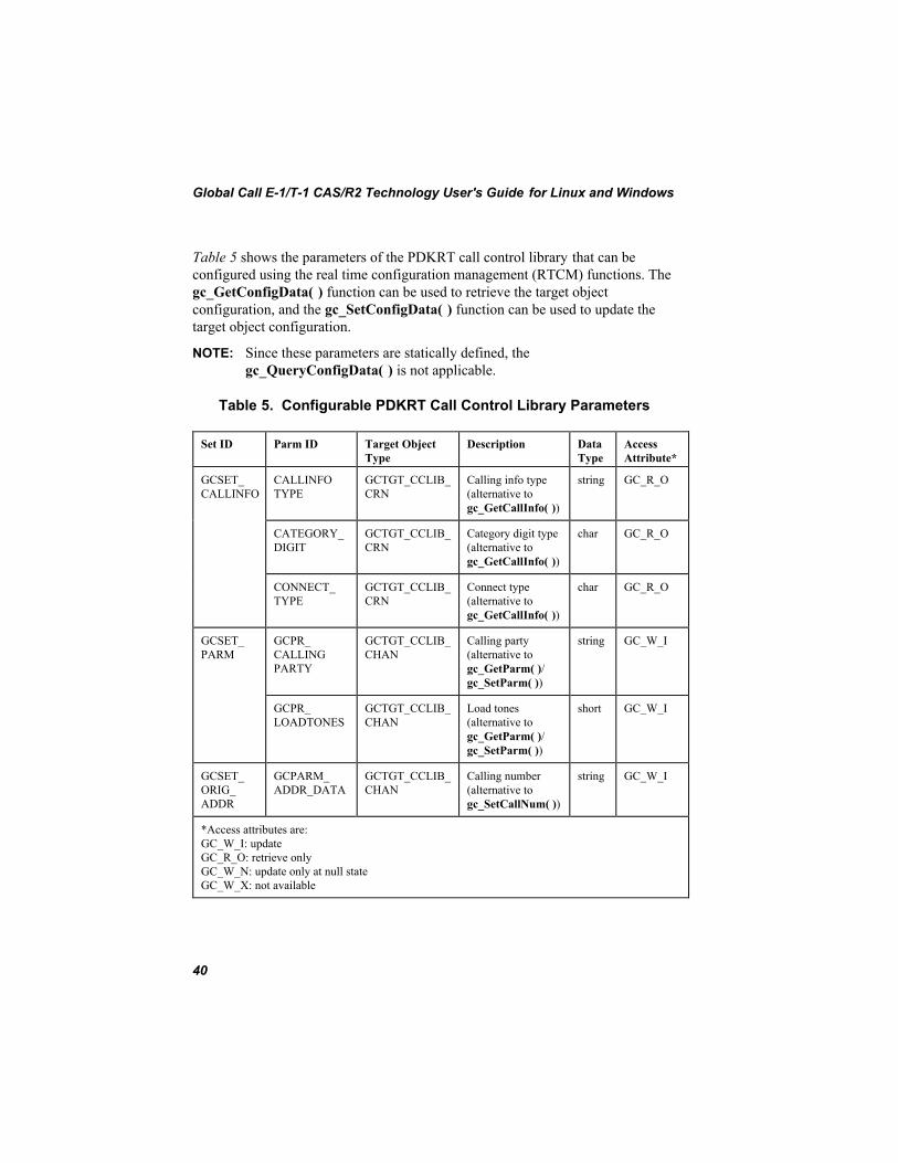
Global Call E-1/T-1 CAS/R2 Technology User's Guide for Linux and Windows
40
Table 5 shows the parameters of the PDKRT call control library that can beconfigured using the real time configuration management (RTCM) functions. Thegc_GetConfigData( ) function can be used to retrieve the target objectconfiguration, and the gc_SetConfigData( ) function can be used to update thetarget object configuration.
NOTE: Since these parameters are statically defined, thegc_QueryConfigData( ) is not applicable.
Table 5. Configurable PDKRT Call Control Library Parameters
Set ID Parm ID Target ObjectType
Description DataType
AccessAttribute*
GCSET_CALLINFO
CALLINFOTYPE
GCTGT_CCLIB_CRN
Calling info type(alternative togc_GetCallInfo( ))
string GC_R_O
CATEGORY_DIGIT
GCTGT_CCLIB_CRN
Category digit type(alternative togc_GetCallInfo( ))
char GC_R_O
CONNECT_TYPE
GCTGT_CCLIB_CRN
Connect type(alternative togc_GetCallInfo( ))
char GC_R_O
GCSET_PARM
GCPR_CALLINGPARTY
GCTGT_CCLIB_CHAN
Calling party(alternative togc_GetParm( )/gc_SetParm( ))
string GC_W_I
GCPR_LOADTONES
GCTGT_CCLIB_CHAN
Load tones(alternative togc_GetParm( )/gc_SetParm( ))
short GC_W_I
GCSET_ORIG_ADDR
GCPARM_ADDR_DATA
GCTGT_CCLIB_CHAN
Calling number(alternative togc_SetCallNum( ))
string GC_W_I
*Access attributes are:GC_W_I: updateGC_R_O: retrieve onlyGC_W_N: update only at null stateGC_W_X: not available

3. Developing Global Call E-1 CAS or T-1 Robbed Bit Applications
41
3.7. Run Time Configuration of PDK Protocol ParametersNOTE: The information in this section is applicable to Springware boards only.
Configurable PDK protocol parameters are grouped into two sets:
• Protocol state information (PSI) variable parameters
• Protocol service layer (PSL) variable parameters
NOTE: To avoid errors, the PSI and PSL parameters of aGCTGT_PROTOCOL_CHAN channel are allowed to be changed onlywhen the channel object does not have an active call.
PSI variable parameters are interpreted by the PDK run-time component(PDKRT).The names of the PSI variable parameters (beginning with CDP_) arefound in the .cdp file. The PSI parameters that can be accessed viagc_GetConfigData( ), gc_SetConfigData( ), and gc_QueryConfigData( ) areprotocol dependent. Refer to the Global Call Country Dependent Parameters(CDP) Reference for further information.
The PSL variable parameters are not available to the protocol state machine, butrather are used by the protocol services layer to control the behavior of variousnetwork and voice functions. The names of the PSL variable parameters beginwith PSL_ and SYS_. No variation in the names is allowed. These parameters arerequired to control protocol parameters (e.g., timing) or they may control thebehavior of the underlying implementation. In the latter case, the parameters willmost likely have a platform tag. All of these parameter names must begin withPSL. The PSL parameters that can be accessed via gc_GetConfigData( ),gc_SetConfigData( ), and gc_QueryConfigData( ) are shown in Table 6.
Table 6. PSL and SYS Parameters
PSL Variable Name Data Type
PSL_AcceptCallDefaultNumOfRings Integer
PSL_AnswerCallDefaultNumOfRings Integer
PSL_MakeCall_CallProgress Integer
PSL_MakeCall_MediaDetect Integer

Global Call E-1/T-1 CAS/R2 Technology User's Guide for Linux and Windows
42
PSL Variable Name Data Type
PSL_DefaultNumOfRingsforAcceptCallandAnswerCall Integer
PSL_DefaultMakeCallTimeout Integer
PSL_DXCAS_HOOKFLASH_DURATION Integer
SYS_FEATURES String
SYS_PSINAME String
Table 7 shows the Set ID and Parm ID for these parameter types.
Table 7. Configurable PDK Protocol Parameters
Set ID Parm ID TargetObject Type
Explanation AccessAttribute**
PDKSET_PSI_VAR *
Dynamicallyassigned
GCTGT_PROTOCOL_SYSTEM,GCTGT_PROTOCOL_CHAN
Protocol state information(PSI) variable parameters
GC_W_N
PDKSET_SERVICE_VAR
Dynamicallyassigned
GCTGT_PROTOCOL_SYSTEM,GCTGT_PROTOCOL_CHAN
Protocol service layer (PSL)variable parameter andsystem parameters
GC_W_N
*Indicates that CAS pattern signals and tones cannot be accessed.**Access attributes are:GC_W_I: updateGC_R_O: retrieve onlyGC_W_N: update only at null stateGC_W_X: not available
The PDK GCTGT_PROTOCOL_SYSTEM target object is not available until thefirst gc_OpenEx( ) function is called to run this protocol.
The Global Call application can call gc_GetConfigData( ) to retrieve protocolconfiguration information or gc_SetConfigData( ) to set protocol configurationinformation. Since these parameters are protocol dependent, their parameters are

3. Developing Global Call E-1 CAS or T-1 Robbed Bit Applications
43
dynamically assigned when a protocol is loaded into the PDKRT. Therefore, aGlobal Call application must call gc_QueryConfigData( ) to find the parameterinformation (set ID, parm ID, and value data type, etc.) first. For more informationabout these functions, refer to the Global Call API Programming Guide .
The pair (target object type, target object ID) supporting gc_QueryConfigData( )to find PDKRT protocol parameter information can be one of the following:
• (GCTGT_PROTOCOL_SYSTEM, Global Call protocol ID)
• (GCTGT_PROTOCOL_CHAN, Global Call line device ID)
For a given protocol, although the GCTGT_PROTOCOL_SYSTEM target objectand GCTGT_PROTOCOL_CHAN target object share the same set ID and parmID for PSI variables, they can have different values. When a newGCTGT_PROTOCOL_CHAN target object is opened, it gets a copy of thecurrent PSI variable configuration of GCTGT_PROTOCOL_SYSTEM targetobject. Under this situation, changes to the GCTGT_PROTOCOL_SYSTEMtarget object configuration will not affect the configuration of theGCTGT_PROTOCOL_CHAN target object. But theGCTGT_PROTOCOL_SYSTEM target object shares the same PSL variableconfiguration with other GCTGT_PROTOCOL_CHAN target objects.
The following example shows how to set the CDP_ANI_ENABLED parameterfor channel ldev running a PDK protocol at the NULL state in asynchronousmode.
NOTE: Error handling is not shown.
GC_PARM t_SourceParm, t_DestParm; GC_PARM_ID t_ParmIDSt; char t_name[20] = “CDP_ANI_ENABLED”; long request_id; LINEDEV ldev; GC_PARM_BLK * t_pParmBlk = NULL;
/* first find the parameter info by calling gc_QueryConfigData() function */ t_SourceParm.padress = t_name; /* Pass the PSI variable name */ memset(&t_ParmIDSt, 0, sizeof(GC_PARM_ID)); t_DestParm.pstruct = &t_ParmIDStruct; /* Pass desired the parm info */ gc_QueryConfigData(GCTGT_PROTOCOL_CHAN, ldev, &t_SourceParm, GCQUERY_PARM_NAME_TO_ID, &t_DestParm);
/* Call GC utility function to insert a parameter data to GC_PARM_BLK */ gc_util_insert_parm_val(&t_pParmBlk, t_ParmIDStruct.set_ID, t_ParmIDStruct.parm_ID, sizeof(int), 10);

Global Call E-1/T-1 CAS/R2 Technology User's Guide for Linux and Windows
44
/* Call gc_SetConfigData() function to set the “CDP_ANI_ENABLE” */ gc_SetConfigData(GCTGT_PROTOCOL_CHAN, ldev, t_pParmBlk, 0, GCUPDATE_ATNULL, &request_id, EV_ASYNC); ... /* Call GC utility function to release the memory after using the GC_PARM_BLK */ gc_util_delete_parm_blk(t_pParmBlk);
3.8. Determining the Protocol VersionNOTE: The information in this section is applicable to Springware boards only.
The following software code demonstrates how you can determine the Global Callprotocol version you are running.
#include <gclib.h>#include <gcerr.h>#include <srllib.h>int main(){ LINEDEV ldev; GC_PARM parm; int retcode; METAEVENT metaevent; parm.paddress = NULL; int mode;ifdef _WIN32 mode = SR_STASYNC|SR_POLLMODE;#else mode = SR__POLLMODE;#endif if (sr_setparm(SRL_DEVICE, SR_MODELTYPE, &mode) == -1) { // Error processing } gc_Start(NULL); retcode = gc_Open(&ldev,":P_na_an_io:N_dtiB1T1:V_dxxxB1C1", 0); if (retcode != GC_SUCCESS) { // Error processing } sr_waitevt(50); retcode = gc_GetMetaEvent(&metaevent); if (retcode != GC_SUCCESS) { // Error processing } if (metaevent.flags & GCME_GC_EVENT) { if (metaevent.evttype == GCEV_UNBLOCKED) { if (gc_GetParm(ldev, GCPR_PROTVER, &parm) == GC_SUCCESS) { printf("The protocol version: %s\n", parm.paddress); } else {

3. Developing Global Call E-1 CAS or T-1 Robbed Bit Applications
45
// Error processing } } }
gc_Close(ldev); gc_Stop(); return(0);}


47
4. Applying Global Call Functions toE-1 CAS or T-1 Robbed BitApplicationsCertain Global Call functions have additional functionality or perform differentlywhen used in an E-1 CAS or a T-1 robbed bit environment. The general functiondescriptions in the Global Call API Library Reference do not contain detailedinformation on a particular technology. Detailed information in terms of theadditional functionality or the difference in performance of those functions in anE-1 CAS or a T-1 robbed bit environment is contained in this chapter. Note thatthis information must be used in conjunction with the information presented in theGlobal Call API Library Reference .
The following sections describe how the functions are used specifically in E-1CAS or T-1 robbed bit applications. The functions are presented alphabetically.See the Global Call API Library Reference for detailed function descriptions.
4.1. gc_AcceptCall( )
On DM3 boards, the rings parameter is ignored.
On Springware boards, the gc_AcceptCall( ) function uses the rings parameter tospecify the number of rings to wait before terminating the function, that is, beforethe Global Call API sends the GCEV_ACCEPT event to the application.
• For PDK protocols, if the rings parameter is set to 0, the value of thePSL_DefaultNumOfRingsforAcceptCallandAnswerCall parameter in thecountry dependent parameters (.cdp) file is used.
• For ICAPI protocols, if the rings parameter is set to 0, the value specified inparameter $9 of the country dependent parameters (.cdp) file is used.
The gc_AcceptCall( ) function optionally responds to an inbound call request byproviding an indication to the remote end that a call was received but not yetanswered. This function causes ringback to be generated.

Global Call E-1/T-1 CAS/R2 Technology User's Guide for Linux and Windows
48
4.2. gc_AnswerCall( )
On DM3 boards, the rings parameter is ignored.
On Springware boards, the gc_AnswerCall( ) function indicates to the remote endthat the connection is established (call has been answered). The rings parameterspecifies the number of rings to wait before terminating the gc_AnswerCall( )function; that is, before answering the call.
• For PDK protocols, if the rings parameter is set to 0, the value of thePSL_DefaultNumOfRingsforAcceptCallandAnswerCall parameter in thecountry dependent parameters (.cdp) file is used.
• For ICAPI protocols, if the rings parameter is set to 0, the value specified inparameter $9 of the country dependent parameters (.cdp) file is used.
4.3. gc_BlindTransfer( )
The gc_BlindTransfer( ) function is only valid for applications using PDKprotocols that support call hold and transfer. Check the sys_features parameter inthe .cdp file for a value of Feature_Transfer. See the Global Call CountryDependent Parameters (CDP) Reference for more information.
4.4. gc_CallAck( )
On DM3 boards, the gc_CallAck( ) function is not supported for E-1/T-1.
On Springware boards, the gc_CallAck( ) function may be called before issuing agc_AcceptCall( ) or a gc_AnswerCall( ) function to indicate to the network ifmore information is desired before completing the call. This function is used torequest additional DDI digits from the network. After using this function, call thegc_GetCallInfo( ) function to retrieve the digits. The gc_GetCallInfo( ) functionwill return all DDI digits collected from the network (including both the digitsalready received and those returned by the network in response to thegc_CallAck( ) function call). Using the gc_CallAck( ) function for this service isdescribed in the Global Call API Library Reference .
4. Applying Global Call Functions to E-1 CAS or T-1 Robbed BitApplications
49
The valid range of values for the gc_CallAck( ) function info_len field is from 1to GCDG_MAXDIGIT. If more than GCDG_MAXDIGIT digits are required, orif an unknown number of digits is to be requested, set the info_len field toGCDG_NDIGIT.
The value GCDG_PARTIAL may be ORed with the number of digits field if theapplication needs to call the gc_CallAck( ) function again for this call (that is, ifthe application needs additional DDI digits before accepting or rejecting the call).
4.5. gc_Close( )
The gc_Close( ) function only affects the link between the calling process and thedevice. For CAS protocols, if a voice resource is currently assigned to thespecified line device, the voice resource will be closed. To keep the voiceresource open for other operations, use the gc_Detach( ) function to detach thevoice resource from the line device before issuing the gc_Close( ) function.
4.6. gc_CompleteTransfer( )
On DM3 boards, the gc_CompleteTransfer( ) function is not supported forE-1/T-1.
On Springware boards, the gc_CompleteTransfer( ) function is only valid forapplications using PDK protocols that support call hold and transfer. Check thesys_features parameter in the .cdp file for a value of Feature_Transfer. See theGlobal Call Country Dependent Parameters (CDP) Reference for moreinformation.
4.7. gc_Detach( )
The gc_Detach( ) function logically disconnects a voice channel from a linedevice. It is the responsibility of the application to make sure that there is a voiceresource available while the gc_WaitCall( ) function is active and that the currentGlobal Call call state is Null or Idle. Furthermore, the gc_Detach( ) function canonly be called in the Null, Idle, or Connected states.

Global Call E-1/T-1 CAS/R2 Technology User's Guide for Linux and Windows
50
4.8. gc_DropCall( )
The gc_DropCall( ) function supports the following values for its causeparameter:
• GC_CALL_REJECTED: call is not accepted
• GC_NETWORK_CONGESTION: cannot establish connection due tovolume of traffic on network
• GC_NORMAL_CLEARING: normal end of call
• GC_SEND_SIT: sends a special information tone
• GC_UNASSIGNED_NUMBER: invalid called party number
• GC_USER_BUSY: called party is busy
CAUTION
You must use the dx_stopch( ) function to terminate any application-initiated voice functions, such as dx_play( ) or dx_record( ), before
calling gc_DropCall( ).
Some protocols do not support all gc_DropCall( ) causes for dropping a call. Anyunsupported cause(s) is automatically mapped to the most appropriate cause. Thisapproach facilitates developing protocol independent applications.
From the Accepted state, some protocols do not support a forced release of theline; that is, issuing a gc_DropCall( ) function after a gc_AcceptCall( ) function.Refer to the Protocol Limitations section in the Global Call Country DependentParameters (CDP) Reference for your protocol. If a forced release is attempted,the function fails and an error is returned. To recover, the application should issuea gc_AnswerCall( ) function followed by gc_DropCall( ) and gc_ReleaseCall( )functions. However, anytime a GCEV_DISCONNECTED event is received in theAccepted state, the gc_DropCall( ) function can be issued.
After the gc_AnswerCall( ) function is issued, the application must wait for aGCEV_ANSWER event. Otherwise the gc_DropCall( ) function is ignored, noerror is returned, and no drop call action is taken.

4. Applying Global Call Functions to E-1 CAS or T-1 Robbed BitApplications
51
When using ICAPI protocols (Springware only), the gc_DropCall( ) functionoccasionally results in the generation of the GCEV_DROPCALL event followedby a GCEV_BLOCKED event. The generation of the GCEV_BLOCKED event ismost likely if the gc_DropCall( ) function is issued before the call is connected.The reason for the GCEV_BLOCKED event is that the remote side does notrecognize the disconnection in a timely manner. When the GCEV_BLOCKEDevent occurs, call-related Global Call functions should not be issued until aGCEV_UNBLOCKED event is detected on the respective device.
In some protocols, a gc_DropCall( ) command on a call in the Accepted staterequires a momentary transition to the Connected state. This may result in acharge being registered for the call.
4.9. gc_Extension( )
On DM3 boards, the gc_Extension( ) function is not supported for E-1/T-1.
On Springware boards, the gc_Extension( ) function provides the capability todynamically configure the behavior of a PDK protocol in a manner that is specificto that protocol. The gc_Extension( ) function is only valid for applications usingPDK protocols that support this feature. Check the associated .cdp file or theGlobal Call Country Dependent Parameters (CDP) Reference for moreinformation regarding the support and configuration of this feature including itsusage.
For PDK protocols that support this feature, up to a maximum of three integervalues and two strings may be passed to the protocol by configuring the parmpparameter as a pointer to a structure of type PDK_EXT_SIG_BLK:
struct pdk_ext_sig_blk { int int1Val; int int2Val; int int3Val; char *str1Val; char *str2Val;} PDK_EXT_SIG_BLK;
The actual meaning and usage of these integers and string values are protocolspecific. The PDKRT library only supports this function in asynchronous mode(EV_ASYNC), and therefore the retvalp parameter is ignored.

Global Call E-1/T-1 CAS/R2 Technology User's Guide for Linux and Windows
52
If the protocol requires unsolicited notification of the application as a result of thecompletion of a feature triggered by the gc_Extension( ) function, or for any otherasynchronous notification for any documented reason, it may send an extensionevent.
The extension event, GCEV_EXTENSION, is provided to support unsolicitedevents resulting from PDK protocol-specific features. Refer to the Global CallCountry Dependent Parameters (CDP) Reference for the proper handling of anyunsolicited extension events as well as the format of the event, that is, identifiermappings and contents of the data buffer.
For this event, the pointer to the extended event data block, exteventdatap, withinthe METAEVENT structure, points to a structure, EXTENSIONEVTBLK,defined as follows:
typedef struct{ unsigned char ext_id; /* unused for PDK protocols */ GC_PARM gcparm; /* GC_PARM union to provide technology-specific info */ short int parm;} EXTENSIONEVTBLK;
The gcparm field of the METAEVENT structure itself points to a structure oftype PDK_EXT_SIG_BLK (above) so that three integers and two string valuesmay be returned from the protocol to the application to indicate protocol-specificstatus information.
The extension block structure, EXTENSIONEVTBLK, referenced in aGCEV_EXTENSION event, has a persistence only until the next call of thegc_GetMetaEvent( ) function. In other words, any information contained orreferenced in a GCEV_EXTENSION event must be either processed or cachedwithin the application, or risk being lost upon the next call of thegc_GetMetaEvent( ) function.
4.10. gc_GetCallInfo( )
For E-1 CAS and T-1 robbed bit protocols that support enhanced call analysis(call progress), the gc_GetCallInfo( ) info_id CONNECT_TYPE parametercontains the type of connection as returned by the function. These connectiontypes are:
• GCCT_CAD: connection due to cadence break
4. Applying Global Call Functions to E-1 CAS or T-1 Robbed BitApplications
53
• GCCT_PVD: connection due to voice detection
• GCCT_PAMD: connection due to answering machine detection
• GCCT_FAX:- connection due to fax machine detection
• GCCT_NA: connection type is not available
PDK protocols provide support for enhanced call analysis.
For protocols that do not support enhanced call progress analysis, thegc_GetCallInfo( ) function with the CONNECT_TYPE parameter specified willreturn a CONNECT_TYPE value of GCCT_NA (not available).
For E-1 CAS protocols that support the CALLINFOTYPE info_id parameter, acall information string containing either a CHARGE or NO CHARGE value isreturned by the parameter; check your protocol in the Global Call CountryDependent Parameters (CDP) Reference for applicability.
On Springware boards, the gc_GetCallInfo( ) function can be used to retrieve theCATEGORY_DIGIT parameter for E-1 CAS calls. (CATEGORY_DIGIT is notsupported on DM3 boards.)
4.11. gc_GetParm( )
The gc_GetParm( ) function retrieves the value of the specified parameter for aline device. In addition to the GCPR_CALLINGPARTY parameter, which iscommon across all technologies and documented in the Global Call API LibraryReference, the following parameters are supported:
• On DM3 boards:
• GCPR_CALLPROGRESS• GCPR_MEDIADETECT• GCPR_MINDIGITS
• On Springware boards:
• GCPR_CALLPROGRESS• GCPR_LOADTONES

Global Call E-1/T-1 CAS/R2 Technology User's Guide for Linux and Windows
54
See Section 4.20. gc_SetParm( ) for more information on the meaning of theseparameters.
4.12. gc_HoldCall( )
On DM3 boards, the gc_HoldCall( ) function is not supported for E-1/T-1.
On Springware boards, the gc_HoldCall( ) function is only valid for applicationsusing PDK protocols that support call hold and transfer. Check the sys_featuresparameter in the .cdp file for a value of Feature_Hold. See the Global CallCountry Dependent Parameters (CDP) Reference for more information.
4.13. gc_MakeCall( )
When using E-1 CAS or T-1 robbed bit line devices, the timeout parameter in thegc_MakeCall( ) function is supported when the mode parameter is set to eitherEV_SYNC or EV_ASYNC.
For ICAPI protocols (Springware only), when the mode parameter is set toEV_ASYNC, the timeout parameter overrides the time-out parameter ($13) valueand the outbound number of ringback tones parameter ($1) in most protocolcountry dependent parameters (.cdp) files.
• If the timeout parameter is set to 0, then the time-out and ringbackparameters in the .cdp file are used to set the time-out conditions.
• If the timeout parameter is set to a value larger than a protocol time-outvalue, a protocol time-out may occur first, which will cause thegc_MakeCall( ) function to fail. The protocol time-out is configured in thecountry dependent parameters (.cdp) file.
• If the timeout value is reached before the remote end answers the call, theapplication is notified of this condition and should respond as described in thegc_MakeCall( ) function description in the Global Call API LibraryReference.
• If all timeout values are set to 0, no time-out condition will apply.

4. Applying Global Call Functions to E-1 CAS or T-1 Robbed BitApplications
55
For PDK protocols, the time-out value used is determined by:
• The timeout parameter in the gc_MakeCall( ) function.
• The PSL_DefaultMakeCallTimeout parameter specified in the .cdp file ifthe timeout parameter in the gc_MakeCall( ) function is 0 and call analysisis not specified.
• The PSL_CallProgressMaxDialingTime parameter specified in the .cdp fileif the timeout parameter in the gc_MakeCall( ) function is 0 and call analysisis specified.
NOTE: PDK protocols do not use the outbound number of ringback tones todefine the time-out.
If your T-1 robbed bit circuit is provisioned for Feature Group A, your applicationshould call the gc_MakeCall( ) function with a null dial string.
If a protocol error occurs during dialing and the default call progress enabledgoverns, then an error code or an event is returned as described in thegc_MakeCall( ) function description in the Global Call API Library Reference . Ifcall progress is disabled and a protocol error occurs during dialing, then aGCRV_BUSY result value or an EGC_BUSY error is returned.
For drop and insert applications, call progress is typically disabled to enable theapplication to complete the dialing sequence, listen for voice or ringback on theline, and:
• if ringback is detected, to transition to the Alerting state
• if voice is detected, to transition to the Connected (call answered) state and toimplement voice cut-through immediately
This methodology enables the application to pass signaling from the remote end(outbound line) to the caller on the inbound line. If call progress is not disabled,then the GCEV_ALERTING event and the GCEV_ANSWERED event may bereceived from the outbound line for an unacceptable amount of time after thedialing sequence was completed. During this period of time, the caller couldmisinterpret the silence on the line as a disconnect or a failure, and then hang upand redial. For further information, see the tips for programming drop and insertapplications in the Global Call API Programming Guide for your operatingsystem.

Global Call E-1/T-1 CAS/R2 Technology User's Guide for Linux and Windows
56
In an E-1 environment, the GCEV_ALERTING event is generated when theequivalent of ringback is recognized. For almost all E-1 protocols, this is arequired part of the protocol, so E-1 applications will receive theGCEV_ALERTING event by default.
In a T-1 environment, the GCEV_ALERTING event is generated when theringback is recognized. However, not all inbound applications will generate aringback tone; for example, the PDK US MF protocol has disabled ringback tonegeneration by default to minimize call setup time. (Detecting the ringback tonetakes several tenths of a second.) If the outbound application does not wish to usethe detection of the ringback tone to generate the GCEV_ALERTING event, theCDP_OUT_Send_Alerting_After_Dialing parameter in the pdk_us_mf_io.cdpfile should be set to 1 (default is 0). That way, if call progress is enabled,GCEV_ALERTING is sent after dialing is initiated rather than when ringback isdetected.
Since GCEV_ALERTING is an optional event triggered by the inbound side, allapplications must be able to handle not receiving the GCEV_ALERTING event.
When the gc_MakeCall( ) function sets up a call, the default is to enable callanalysis (call progress). To change the enabled call progress default when makinga call on Springware boards, see Section 4.13.1. PDK_MAKECALL_BLK forPDK protocols and Section 4.13.2. IC_MAKECALL_BLK for ICAPI protocols.(These structures do not apply to DM3 boards, which use gc_SetParm( )parameters to change call progress configuration as discussed in Section3.2.1. Call Analysis with DM3 Boards.)
4.13.1. PDK_MAKECALL_BLK
For PDK protocols, when the gc_MakeCall( ) function sets up a call, the defaultis to enable call analysis (call progress). This default can be changed on a callbasis by setting the flags parameter in the PDK_MAKECALL_BLK datastructure. See Table 8. PDK_MAKECALL_BLK Field Descriptions.

4. Applying Global Call Functions to E-1 CAS or T-1 Robbed BitApplications
57
The PDK_MAKECALL_BLK structure contains information used by thegc_MakeCall( ) function when setting up a call. The structure is defined asfollows:
typedef struct pdk_makecall_blk{ unsigned long flags; void *v_rfu_ptr; unsigned long ul_rfu[4]; }PDK_MAKECALL_BLK;
Table 8. PDK_MAKECALL_BLK Field Descriptions
Field Description
flags Controls call analysis and media type detection on a per callbasis. The flags included are:
• NO_CALL_PROGRESS: Set to 0 to enable call analysis(default). Set to 1 to disable call analysis.
• MEDIA_TYPE_DETECT: Set to 0 to enable media typedetection. Set to 1 to disable media type detection.
*v_rfu_ptr Reserved for future use.
ul_rfu[4] Reserved for future use.
4.13.2. IC_MAKECALL_BLK
For ICAPI protocols, when the gc_MakeCall( ) function sets up a call, the defaultis to enable call analysis (call progress). This default can be changed on a callbasis by setting the flags parameter in the IC_MAKECALL_BLK data structure.See Table 9. IC_MAKECALL_BLK Field Descriptions.
The IC_MAKECALL_BLK structure contains information used by thegc_MakeCall( ) function when setting up a call. The structure is defined asfollows:
typedef struct ic_makecall_blk{ unsigned long flags; void *v_rfu_ptr; unsigned long ul_rfu[4];}IC_MAKECALL_BLK;

Global Call E-1/T-1 CAS/R2 Technology User's Guide for Linux and Windows
58
Table 9. IC_MAKECALL_BLK Field Descriptions
Field Description
flags Controls call analysis and media type detection on a per callbasis. The flags included are:
• NO_CALL_PROGRESS: Set to 0 to enable call analysis(default). Set to 1 to disable call analysis.
*v_rfu_ptr Reserved for future use.
ul_rfu[4] Reserved for future use.
4.14. gc_OpenEx( )
The gc_OpenEx( ) function is used to open both network board and channel (timeslot) devices. This generic call control function initializes the specified time sloton the specified trunk. A line device ID will be returned to the application. TheE-1 or T-1 feature of this function specifies the voice device as part of thedevicename parameter.
4.14.1. Conventions for Specifying the devicename Parameter
A device is specified by the devicename parameter using a format that includesprotocol specific information.
The format for the fields used to specify this parameter is:
:N_<network_device_name>:P_<protocol_name>:V_<voice_channel_name>
The prefixes (N_, P_, and V_) are used for parsing purposes. These fields mayappear in any order. The fields within the devicename parameter must each beginwith a colon.

4. Applying Global Call Functions to E-1 CAS or T-1 Robbed BitApplications
59
The conventions described below allow the Global Call API to map subsequentcalls made on specific line devices or CRNs to interface-specific libraries.
• <network_device_name>: This field is required. It may be a board name ora time slot name:
• If <network_device_name> is a board name, use the format:dtiB<number of board>.
• If <network_device_name> is a time slot name, use the format:dtiB<number of board>T<number of time slot>.
• <protocol_name>: This field is required on Springware boards. It specifiesthe protocol to use. Use the root file name of the country dependentparameters (.cdp) file.
NOTE: On DM3 boards, the protocol is determined at board initializationtime and not when a Global Call device is opened. For compatibility,the <protocol_name> field may be specified, but it is not used.
• <voice_channel_name>: This field is optional depending on your application(see Section 5.1. Dedicated Voice Resources or Section 5.2. Shared VoiceResources). It specifies the name of the voice channel to be associated withthe device being opened. Use the following format: dxxxB<virtual boardnumber>C<channel number>.
NOTE: Attachment to different types of DM3 voice devices is dependent onthe protocol downloaded. For example, if one board has ISDN forprotocols and another has T-1 CAS, the T-1 CAS network devicescannot be attached to the voice devices on the ISDN board. See theGlobal Call API Programming Guide for further information.
4.14.2. Examples of the devicename Parameter
The following examples illustrate the devicename parameter when using E-1ICAPI protocols:
• For a D/300SC-E1 board specified as dtiB3, the devicename for time slot 1on this board using the inbound Brazil protocol is:
:N_dtiB3T1:P_br_r2_i

Global Call E-1/T-1 CAS/R2 Technology User's Guide for Linux and Windows
60
• To open both voice channel 2 on virtual voice board 4 and the above networkdevice, the devicename for the inbound Brazil protocol is:
:N_dtiB3T1:P_br_r2_i:V_dxxxB4C2
• A line device may represent a board, thus to open the board dtiB1, thedevicename is:
:N_dtiB1:P_br_r2_i
4.14.3. Other gc_OpenEx( ) Considerations
For E-1 CAS or T-1 robbed bit applications, always specify a network resource(board or time slot level) and a protocol. A voice resource(<voice_channel_name>) may also be specified for E-1 CAS or T-1 robbed bitoperations. When a voice resource is specified, Global Call automatically opensthe voice device and internally attaches the voice device to the line device.
When using the CT Bus and a voice resource is specified, the gc_OpenEx( )function routes the voice and network resources together.
When the voice resource is not specified, the application must perform thesefunctions (open device, route, attach); see Section 5.1. Dedicated VoiceResources and Section 5.2. Shared Voice Resources for details.
When a network resource is specified, the gc_OpenEx( ) function internallyissues a dt_open( ) function. Likewise, when a voice resource is specified, thegc_OpenEx( ) function internally issues a dx_open( ) function. Thecorresponding network or voice device handle may be retrieved using thegc_GetResourceH( ) function. These lower level device handles may be usefulfor routing or for playing or recording a file.
If a gc_OpenEx( ) function fails with an error value of EGC_DXOPEN, then theinternally issued dx_open( ) function failed. If a gc_OpenEx( ) function fails withan error value of EGC_DTOPEN, then the internally issued dt_open( ) functionfailed.

4. Applying Global Call Functions to E-1 CAS or T-1 Robbed BitApplications
61
4.15. gc_ResetLineDev( )
On Springware boards, for applications that use PDK protocols, thegc_ResetLineDev( ) function cannot be called while there is an alarm on the line.
On Springware boards, for applications that use ICAPI protocols, thegc_ResetLineDev( ) function is not supported in synchronous mode. If theapplication calls gc_ResetLineDev( ) on a line device in synchronous mode (thatis, with the mode parameter set to EV_SYNC), the function fails silently.
There are no restrictions on using gc_ResetLineDev( ) with DM3 boards.
4.16. gc_RetrieveCall( )
On DM3 boards, the gc_RetrieveCall( ) function is not supported for E-1/T-1.
On Springware boards, the gc_RetrieveCall( ) function is only valid forapplications using PDK protocols that support call hold and transfer. Check thesys_features parameter in the .cdp file for a value of Feature_Hold. See theGlobal Call Country Dependent Parameters (CDP) Reference for moreinformation.
4.17. gc_SetBilling( )
On DM3 boards, the gc_SetBilling( ) function is not supported for E-1/T-1.
On Springware boards, the gc_SetBilling( ) function sets different billing rates ona per call basis. For example:
• To charge the call, use gc_SetBilling(crn, GCR_CHARGE, NULL,EV_SYNC)
• To select no-charge for the call, use gc_SetBilling(crn,GCR_NOCHARGE, NULL, EV_SYNC)
The gc_SetBilling( ) function is called after the GCEV_OFFERED event arrivesand before issuing a gc_AcceptCall( ) or gc_AnswerCall( ) function.

Global Call E-1/T-1 CAS/R2 Technology User's Guide for Linux and Windows
62
Not all protocols support this feature; see the Global Call Country DependentParameters (CDP) Reference for protocol specific limitations.
The mode parameter must be set to EV_SYNC. Asynchronous mode(EV_ASYNC) is not supported for this function.
4.18. gc_SetChanState( )
The GCLS_INSERVICE and GCLS_OUT_OF_SERVICE states are the onlyvalid service states that can be used to set the state of a line in an E-1 CAS or T-1robbed bit environment.
4.19. gc_SetEvtMsk( )
On DM3 and Springware boards using PDK protocols, all of the mask parametervalues are supported. See the gc_SetEvtMsk( ) function reference page in theGlobal Call API Library Reference for more information.
On Springware boards using ICAPI protocols, the following mask parametervalues are supported:
• GCMSK_ALERTING
• GCMSK_BLOCKED
• GCMSK_UNBLOCKED
4.20. gc_SetParm( )
The gc_SetParm( ) function sets the default parameters and all channelinformation associated with the specific line device. In addition to theGCPR_CALLINGPARTY parameter, which is common across all technologiesand documented in the Global Call API Library Reference , the parameters listedin Table 10 are supported.
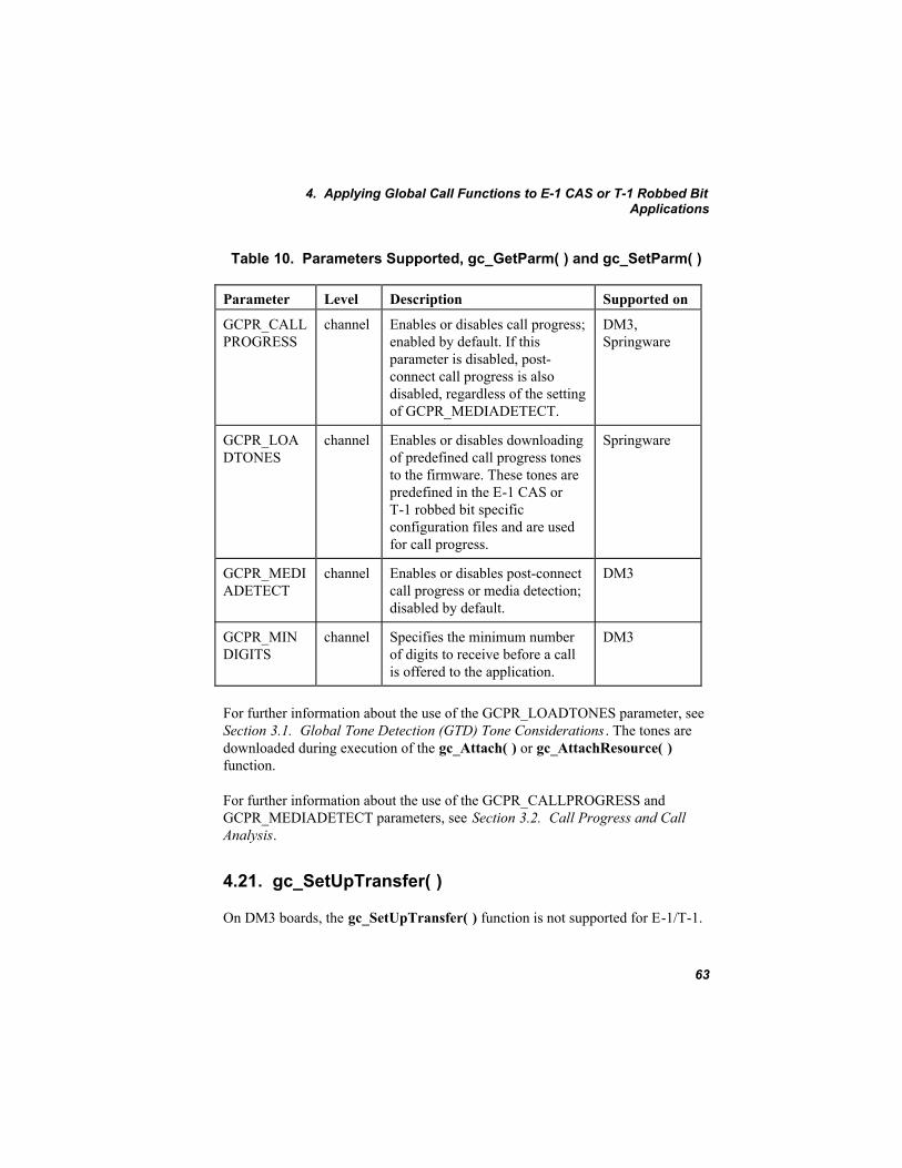
4. Applying Global Call Functions to E-1 CAS or T-1 Robbed BitApplications
63
Table 10. Parameters Supported, gc_GetParm( ) and gc_SetParm( )
Parameter Level Description Supported on
GCPR_CALLPROGRESS
channel Enables or disables call progress;enabled by default. If thisparameter is disabled, post-connect call progress is alsodisabled, regardless of the settingof GCPR_MEDIADETECT.
DM3,Springware
GCPR_LOADTONES
channel Enables or disables downloadingof predefined call progress tonesto the firmware. These tones arepredefined in the E-1 CAS orT-1 robbed bit specificconfiguration files and are usedfor call progress.
Springware
GCPR_MEDIADETECT
channel Enables or disables post-connectcall progress or media detection;disabled by default.
DM3
GCPR_MINDIGITS
channel Specifies the minimum numberof digits to receive before a callis offered to the application.
DM3
For further information about the use of the GCPR_LOADTONES parameter, seeSection 3.1. Global Tone Detection (GTD) Tone Considerations . The tones aredownloaded during execution of the gc_Attach( ) or gc_AttachResource( )function.
For further information about the use of the GCPR_CALLPROGRESS andGCPR_MEDIADETECT parameters, see Section 3.2. Call Progress and CallAnalysis.
4.21. gc_SetUpTransfer( )
On DM3 boards, the gc_SetUpTransfer( ) function is not supported for E-1/T-1.
Global Call E-1/T-1 CAS/R2 Technology User's Guide for Linux and Windows
64
On Springware boards, the gc_SetUpTransfer( ) function is only valid forapplications using PDK protocols that support call hold and transfer. Check thesys_features parameter in the .cdp file for a value of Feature_Transfer. See theGlobal Call Country Dependent Parameters (CDP) Reference for moreinformation.
4.22. gc_Start( ) and gc_Stop( )
On Springware boards using PDK protocols, the gc_Start( ) function is used toaccess the error and debug logging capabilities of the PDKRT call control library.See Section 7.1. Debugging Applications that Use PDK Protocols for moreinformation.
On Springware boards using ICAPI protocols, when the gc_Start( ) function iscalled, a log file, if enabled, is created. This file logs debug information for allICAPI call control libraries for all open channels. The log file remains open untilthe gc_Stop( ) function is called. This allows channels to be opened, closed, andreopened multiple times without overwriting or otherwise affecting the continuityof the log file. See Section 7.2. Debugging Applications that Use ICAPIProtocols for more information.
4.23. gc_StartTrace( )
On DM3 boards, the gc_StartTrace( ) function is not supported for E-1/T-1.
On Springware boards using PDK protocols, the gc_StartTrace( ) function canbe used to enable logging on individual channels. This function has no effectunless the name of the log file and the logging level have been set using thegc_Start( ) function. The gc_StartTrace( ) filename parameter is ignored. Thename of the log file is specified in the PDK_START_STRUCT data structure. SeeSection 7.1. Debugging Applications that Use PDK Protocols for moreinformation.
4.24. gc_SwapHold( )
On DM3 boards, the gc_SwapHold( ) function is not supported for E-1/T-1.

4. Applying Global Call Functions to E-1 CAS or T-1 Robbed BitApplications
65
On Springware boards, the gc_SwapHold( ) function is only valid for applicationsusing PDK protocols that support call hold and transfer. Check the sys_featuresparameter in the .cdp file for a value of Feature_Transfer. See the Global CallCountry Dependent Parameters (CDP) Reference for more information.


67
5. Resource Allocation and Routing E-1 CAS and T-1 robbed bit protocols require tone generation and detectioncapability and therefore require a voice or tone resource for setting up a call.Application development considerations for using dedicated voice (or tone)resources or shared voice (or tone) resources in an E-1 CAS and T-1 robbed bitenvironment are discussed in this chapter.
5.1. Dedicated Voice Resources
Applications requiring voice resources during the entire call (for example, voice-mail and announcements) must have enough voice channels to dedicate onechannel to each network interface time slot. Global Call simplifies applicationswritten to handle E-1 CAS and T-1 robbed bit protocols using dedicated voiceresource configurations. To use Global Call functionality to set up dedicatedresources, the application must pass both the network time slot and the voicechannel to the gc_OpenEx( ) function. The Global Call API uses this informationto automatically:
• open the network board device, if not previously opened (the board device isused internally by Global Call)
• open both the voice channel and the network time slot
• route the voice channel and network time slot together (full duplex) (CT Busconfigurations only)
• associate the voice channel and the network time slot by issuing an internalgc_Attach( ) function
For CT Bus applications, applications using dedicated voice resources (a voiceresource dedicated to a network resource) do not need to route the voice andnetwork resources together nor issue the gc_Attach( ) function before making acall or when handling a pending call. For applications using shared voiceresources, the voice resource must be attached to a network resource before callestablishment. After call establishment, this voice resource may be detached andthen attached to a different network resource.

Global Call E-1/T-1 CAS/R2 Technology User's Guide for Linux and Windows
68
To perform activities such as routing and voice store and forward, etc., use thegc_GetResourceH( ) function to obtain the voice and network handles associatedwith a line device. For example, before playing a file, you can retrieve the voicehandle using the gc_GetResourceH( ) function. If needed, you may route otherresources to the network interface (for example, to send a fax) and reroute thevoice channel back to the network interface before setting up or waiting foranother call. You must route the same voice channel back to the associatednetwork interface channel because these two resources were internally attachedwhen opened.
The following example illustrates the function calls that apply when usingdedicated voice resources.

5. Resource Allocation and Routing
69
5.1.1. Dedicated Voice Resources Example..#define MAXCHAN 30struct linebag{ LINEDEV ldev; CRN crn; INT state;}port[MAXCHAN+1]../* Open a Global Call device with a voice channel and a network time slot */
1 ----> if (gc_OpenEx(&linedev, “:N_dtiB1T1:P_br_r2_o:V_dxxxB1C1”, 0, (void*)&port[port_index]) == GC_SUCCESS) { /* * Wait for GCEV_UNBLOCKED event. */ . . /* Make an outgoing call */
2 ----> if (gc_MakeCall(linedev, &crn, “123456”, NULL, 0, EV_ASYNC) == GC_SUCCESS) { /* * Wait for GCEV_CONNECTED event. */ } else { /* Process error from gc_MakeCall( ) */ }} else { /* Process error from gc_Open( ) */}..
Legend:
1 The gc_OpenEx( ) function:• opens a Global Call line device using time slot 1 of dtiB1, opens
voice channel dxxxB1C1, and configures the line device to useoutbound Brazilian R2 protocol
• opens the time slot and voice channel automatically• opens the network board device automatically, if not already opened
to monitor the alarm• sets the user attribute, usrattr, (void*)&port[port_index] into the
channel information structureCT Bus time slot routing and attaching are done automatically. Thefunction need only be called once for a time slot/voice channel pair.
2 The gc_MakeCall( ) function is invoked once for each outbound call.

Global Call E-1/T-1 CAS/R2 Technology User's Guide for Linux and Windows
70
5.2. Shared Voice Resources
Applications requiring voice resources for a limited portion of the call, typicallyduring call setup, may share voice resources among the available network timeslots. For example, using a D/320SC voice board and two DTI/300SC (E -1interface) network boards, 32 voice channels may be able to handle the audioportions of the call control for 60 network interface time slots. This savings inhardware requires more complexity in writing the application, which must manageboth the voice and network resources, and places limits on your call throughput.The number of calls that can be established simultaneously is limited to thenumber of voice resources in the system.
For voice resource sharing configurations, you need only specify the network timeslot and protocol in the gc_OpenEx( ) function. This function uses the GlobalCall library to open the network time slot device. Your application must also openthe voice device and then route and attach the necessary resources before theseresources are needed for signaling. You must explicitly open the voice device byissuing a dx_open( ) function to open the voice device selected. For routing thesedevices, use the native time slot routing functions or the CT Bus nr_scroute( )and nr_scunroute( ) functions provided for the voice and network devices. Forexample, route the devices using the routing functions provided by the networkand voice libraries, and then use the gc_Attach( ) and gc_Detach( ) functions toassociate or disassociate a voice channel and a Global Call line device andtherefore a network time slot. When the above sequence of operations completes,use the gc_MakeCall( ) or gc_WaitCall( ) function, as appropriate.
After a call is answered, the voice resource can be detached from the network timeslot using the gc_Detach( ) function and routed to another network time slot usingthe nr_scunroute( ) and nr_scroute( ) functions.
The following example illustrates the function calls that apply when using sharedvoice resources.

5. Resource Allocation and Routing
71
5.2.1. Shared Voice Resources Example
1 ----> if (gc_OpenEx(&linedev, “:N_dtiB1T1:P_br_r2_o, 0, (void*)&port[port_index]) == GC_SUCCESS) { /* process error */}
2 ----> if (gc_GetNetworkH(linedev, &networkh) != GC_SUCCESS){ /* process error */}
3 ----> if ((voiceh = dx_open("dxxxB1C1", 0)) == -1){ /* process error */}
4 ----> printf("******* %d: Calling Attach %d\n", index, voiceh);if (gc_Attach(linedev, voiceh, EV_SYNC) != GC_SUCCESS){ /* process error */}
5 ----> if (nr_scroute(networkh, SC_DTI, voiceh, SC_VOX, SC_FULLDUP) == -1) { /* process error */ } /* Wait for GCEV_UNBLOCKED event */
6 ----> if (gc_MakeCall(linedev, &crn, "123456", NULL, 0, EV_ASYNC) != GC_SUCCESS) { /* process error */ }../* * Wait for GCEV_CONNECTED event. Voice resource may be detached * if necessary after receiving this event. */
7 ----> if (gc_Detach(linedev, voiceh, EV_SYNC) != GC_SUCCESS) { /* process error */ }
8 ----> if (nr_scunroute(networkh, SC_DTI, voiceh, SC_VOX, SC_FULLDUP) == -1){ /* process error */}
Legend:
1 The gc_OpenEx( ) function:
• opens a Global Call line device using time slot 1 of dtiB1 usingoutbound Brazilian R2 protocol

Global Call E-1/T-1 CAS/R2 Technology User's Guide for Linux and Windows
72
• opens the network board device automatically, if not already opened• sets the user attribute, usrattr, (void*)&port[port_index] into the
channel information structureThe specified network time slot device is opened. This function needonly be called once for a time slot.
2 The gc_GetNetworkH( ) function retrieves network device handle.3 The dx_open( ) function opens voice device and gets voice device
handle.4 The gc_Attach( ) function logically connects voice and network
resources.5 The nr_scroute( ) function routes voice and network resources together.6 The gc_MakeCall( ) function is invoked each time a call is to be made.7 The gc_Detach( ) function disassociates the voice resource from the
Global Call line device.8 The nr_scunroute( ) function unroutes the voice and network resources.
73
6. ProtocolsThe protocols supported, protocol naming conventions, protocol components, andtheir corresponding protocol files are described in this chapter.
NOTES: 1. See the documentation accompanying the Global Call Protocolspackage for more information about using the protocols and thecountry dependent parameter (CDP) files.
2. The development of the ICAPI protocols supported by Global Callhas been capped. Customers should migrate to equivalent protocolsdeveloped using the Protocol Development Kit (PDK). New protocoldevelopment as well as existing protocol support will be on the PDK.ICAPI protocols are supported only on Springware boards. PDKprotocols are supported on both DM3 boards and Springware boards.
6.1. Protocols Supported
Protocols are distributed separately on individual CDs or as part of a softwarepackage release. This modular design simplifies adapting applications for use innumerous countries. The Global Call protocols available are listed in the GlobalCall Country Dependent Parameters (CDP) Reference . For the most up-to-datelist of available protocols, contact your nearest Intel Sales Office.
The protocol and parameters used at the application�s interface to the PTT mustcomplement those used by the local CO. To maintain compatibility with the localPTT, Intel provides .cdp country dependent parameter files that can be modifiedto satisfy local requirements. User selectable options allow customization of thecountry dependent parameters to fit a particular application or configurationwithin a country (for example, switches within the same country may use the sameprotocol but may require different parameter values for local use). Theseparameters (for example, the number of DNIS digits, time-outs, party callingnumber, idle patterns, signaling patterns, and protocol-specific definitions) arespecified in the .cdp file and may be modified at configuration time (that is, at anytime before starting your application). See the Global Call Country DependentParameters (CDP) Reference for additional information.

Global Call E-1/T-1 CAS/R2 Technology User's Guide for Linux and Windows
74
6.2. Protocol File Naming Conventions
When a protocol is installed on your system, several files are installed, includingthe protocol module(s), firmware parameter files, and country dependentparameter files. For most protocols, the files are named according to theconventions in Table 11.
Table 11. Protocol File Naming Conventions
File Name Description
ccl_cc_tt_d.hot andccl_cc_tt_d.qs
PDK protocol module (DM3)
ccl_cc_tt_d.psi PDK protocol module (Springware)ccl_cc_tt_d.so orccl_cc_tt_ffff_d.so
ICAPI protocol module for Linux (Springware only)
ccl_cc_tt_d.dll orccl_cc_tt_ffff_d.dll
ICAPI protocol module for Windows (Springwareonly)
ccl_cc_tt_d.cdp orccl_cc_tt_ffff_d.cdp
Country dependent parameter file (DM3 andSpringware)
ccl_cc_nn0.prm Country-specific voice and network parameter file(Springware only)
where:
• ccl indicates the call control library for which the protocol is written, forexample, pdk represents the PDKRT call control library. For the ICAPI callcontrol library, ccl is blank.
• cc is a 2-character ISO country code, regional code (for example, es = Spain,fr = France, mx = Mexico, na = North America, etc.), or an indication of aswitch-specific protocol.
• tt is a 2-character protocol type. Valid types are:
• em: a T-1 protocol using E&M signaling with support for DTMF digitsonly
• mf: a T-1 protocol using E&M signaling with support for MF digits• r2: a protocol using R2 MFC signaling• r1: a protocol using R1 MFC signaling

6. Protocols
75
• e1: a pulse, MF SOCOTEL, or other E-1 protocol• sw: a protocol that is switch specific• ls: a loop start protocol
• d is a 1- or 2-character direction indicator. Valid directions are:
• i: inbound• o: outbound• io: inbound/outbound
• ffff is optional and defines a special software or hardware feature supportedby the protocol; 1 to 4 characters. If the protocol type is �sw�, then this fieldprovides additional information about the switch.
NOTE: Requires ICAPI call control library level 2, or else a compatibilityerror, EGC_COMPATIBILITY, will be generated when theapplication attempts to load the protocol.
• nn is the number of channels in a single span, typically 24 for T-1 and 30 forE-1.
The protocol name used in the devicename parameter of the gc_OpenEx( )function is the root name of the .cdp file. Most ICAPI protocol releases useseparate protocol modules to handle the inbound and the outbound portions of aprotocol. For example, Table 12 describes the files included for the Argentina R2ICAPI protocol.
Table 12. Sample ICAPI Protocol File Set
Description Protocol FilesLinux Windows
Inbound protocol module ar_r2_i.so ar_r2_i.dllOutbound protocol module ar_r2_o.so ar_r2_o.dllInbound country dependent parameters ar_r2_i.cdp ar_r2_i.cdpOutbound country dependent parameters ar_r2_o.cdp ar_r2_o.cdpVoice and network firmware parameters ar_300.prm ar_300.prm
PDK protocols are bidirectional protocols. For example, Table 13 describes thefiles included with the Argentina R2 PDK protocol.

Global Call E-1/T-1 CAS/R2 Technology User's Guide for Linux and Windows
76
Table 13. Sample PDK Protocol File Set
Description Protocol FilesLinux and Windows
Bidirectional protocol module (DM3) pdk_ar_r2_io.hot,pdk_ar_r2_io.qs
Bidirectional protocol module (Springware) pdk_ar_r2_io.psiBidirectional country dependent parameters(DM3 and Springware)
pdk_ar_r2_io. cdp
Voice and network firmware parameters(Springware only)
ar_300.prm
6.3. Protocol Components
Each protocol requires specific firmware parameter file(s) to be downloaded tothe voice and network boards. The following files are included on the Global CallProtocols CD:
• protocol modules
• country dependent parameters (.cdp) files
• standard voice and network firmware parameter (.prm) files for the country
6.3.1. Protocol Modules
These files contain protocol specific information and are dynamically linked to theapplication as needed.
PDK protocols are supported on both DM3 and Springware boards. For DM3boards, the protocol modules are .hot and .qs files. For Springware boards, theprotocol module is a protocol state information ( .psi) file, a binary file that isinterpreted by the PDK run-time component (PDKRT).
ICAPI protocols are supported on Springware boards only. The protocol modulesfor Linux are .so files. The protocol modules for Windows are .dll files.

6. Protocols
77
6.3.2. Country Dependent Parameter (.cdp) Files
These files contain country specific and protocol specific parameters for use byGlobal Call. Country dependent parameter (.cdp) files may be customized.Descriptions of the country dependent parameters most likely to be modified for aprotocol are provided in the Global Call Country Dependent Parameters (CDP)Reference.
For ICAPI protocols, the special parameter @0 identifies the protocol to be run.This parameter specifies the name of the protocol module (ignoring the filenameextension and without the path) to be run by the application. Two variations of thesame protocol can be run if two .cdp files point to the same protocol modulefilename after @0.
The .cdp file should be located only under the installation directory:
• For Linux: /usr/dialogic/cfg
• For Windows: x:\Program Files\Dialogic\cfgwhere x is a drive name.
6.3.3. Parameter (.prm) Files (Springware only)
For some protocols, certain parameters must be specified in the firmwareparameter (.prm) file to ensure proper operation of the protocol. Refer to theGlobal Call Country Dependent Parameters (CDP) Reference for any requiredsettings.
The .prm files are located:
• For Linux: /usr/dialogic/data
• For Windows: x:\Program Files\Dialogic\datawhere x is a drive name.
The following paragraphs describe configuration steps required when using .prmfiles on Linux and Windows.
Global Call E-1/T-1 CAS/R2 Technology User's Guide for Linux and Windows
78
Using .prm Files on Linux
When the Global Call Protocols package is installed on your system, thecc_nn0.prm file is installed. The cc_nn0.prm file contains both the voice andnetwork parameters required by the Global Call API.
You must set the Country parameter for Linux in the/usr/dialogic/cfg/dialogic.cfg file for each board to specify the cc_nn0.prm file asshown below:
ParameterFile = cc_nn0.prm
where:
• cc is the country code
• nn is the number of time slots per trunk
For some protocols, different firmware parameters may be needed to supportdifferent variants of the protocol. See the Global Call Country DependentParameters (CDP) Reference for specific instructions regarding parameterselection. To use parameter values in the cc_nn0.prm file that differ from thedefault values, you must set the ParamFeature parameter in the/usr/dialogic/cfg/dialogic.cfg file for each board so as to specify the protocolvariant to use.
Using (.prm) Files on Windows
When the Global Call Protocols package is installed on your system, thecc_nn0.prm file is installed. The cc_nn0.prm file contains both the voice andnetwork parameters required by the Global Call API.
Use the Intel® Dialogic® Configuration Manager (DCM) utility to configure eachboard in your system:
1. Select the board to be configured.
2. Select the Country tab.
3. Select the country name from the pull down menu.

6. Protocols
79
4. Use the Edit window to change parameter values for the board and countryselected.
For some protocols, different firmware parameters may be needed to supportdifferent variants of the protocol. See the Global Call Country DependentParameters (CDP) Reference for specific instructions regarding parameterselection. To use parameter values in the cc_nn0.prm file that differ from thedefault values, use the DCM to set the firmware parameters to the desired value.


81
7. Debugging ApplicationsThe Global Call debugging utilities are described in this chapter.
NOTE: The information in this chapter is applicable to Springware boards only.There are no specific protocol debugging capabilities for DM3 boards.Debugging of DM3 applications can usually be done with RTF logs.
Global Call includes powerful debugging capabilities for troubleshootingprotocol-related problems, including the ability to generate a detailed log file.These debugging tools should not be used during normal operations or whenrunning an application for an extended period of time since they increase theprocessing load on the system and they can quickly generate a large log file.
NOTE: Only run the debugging and logging utilities on a limited number ofchannels at a time to avoid the possibility of losing events.
The following sections discuss:
• Debugging applications that use PDK protocols
• Debugging applications that use ICAPI protocols
7.1. Debugging Applications that Use PDK Protocols
The Global Call PDKRT (Protocol Development Kit Run Time) provides a richset of logging features that are useful to protocol developers and implementers ofthe engine and call control libraries. The application may add additional logrecords to the log file when logging is enabled.
Global Call E-1/T-1 CAS/R2 Technology User's Guide for Linux and Windows
82
7.1.1. Enabling and Disabling the Logging
CAUTIONIt is recommended to use logging on an as-needed basis. Logging uses
significant resources and can reduce the performance of the Global CallPDKRT call control library. Full logging (debug logging) enabled on
many channels can reduce performance to such a degree that time-criticaloperations are affected and the behavior of a protocol may be altered.
The LogView tool is required to view the log file.
The PDKRT call control library provides a service for capturing error and debuginformation in a log file. Enabling and disabling logging is achieved using thegc_Start( ) function. Once logging is enabled, the gc_StartTrace( ) function canbe used to enable logging on each individual channel. SeeSection 4.22. gc_Start( ) and gc_Stop( ) and Section 4.23. gc_StartTrace( ) formore information.
The parameters that control the logging mechanism can be set by:
• Populating and using a CCLIB_START_STRUCT. See Section7.1.2. Populating and Using a CCLIB_START_STRUCT .
• Defining the GC_PDK_START_LOG environment variable. See Section7.1.3. Defining the GC_PDK_START_LOG Environment Variable .
When both methods are used, the CCLIB_START_STRUCT takes precedenceover the GC_PDK_START_LOG environment variable.
NOTE: Two applications should not use the same log file.
7.1.2. Populating and Using a CCLIB_START_STRUCT
The following code shows an example of how to define aCCLIB_START_STRUCT, populate the fields, and use it to enable logging whenissuing the gc_Start( ) function.
GC_START_STRUCT t_GcStart; CCLIB_START_STRUCT t_PdkStart; t_PdkStart.cclib_name = “GC_PDKRT_LIB”;

7. Debugging Applications
83
t_PdkStart.cclib_data = "filename: pdktest.log; loglevel: ENABLE_DEBUG; service: R2MF_ENABLE | CAS_ENABLE; cachedump: WHEN_FULL | THREAD_ON; channel: B1C1, B2C2-4; cachesize: 10; maxfilesize: 0; mindiskfree: 20"; t_GcStart.num_cclibs = 1; t_GcStart.cclib_list = (void *) (& t_PdkStart); int t_result = gc_Start((GC_START_STRUCTP)& t_GcStart);
NOTE: The example above shows all the possible fields in a cclib_data string.In practice, you only need to specify the values of fields that are differentthan the default values.
The length of the filename must be less than 8 characters.
The value of the cclib_name field must be GC_PDKRT_LIB and the cclib_datafield should have the following format:
“field name 1 : field value 1; field name 2 : field value 2; ...”
where the allowable field names and values are given in Table 14.
Table 14. cclib_data Fields and Values
Field Name Field Values Default Value
filename Log file name gc_pdk.log
loglevel See Table 15. ENABLE_FATAL or 5
service See Table 16. ALL_SERVICES
cachedump See Table 17. WHEN_FULL or 1
cachesize Any positive integer 1 (number of records in cache)
channel See Table 18. B*C*
maxfilesize Integer 0 (Megabytes)
mindiskfree Integer 20 (Megabytes)

Global Call E-1/T-1 CAS/R2 Technology User's Guide for Linux and Windows
84
The fields can be defined in any sequence. If any field is not defined or definedincorrectly (either in name or value), then the default value is used for logging.The actual values of the fields are posted as the first record of the log file. In thisway, when a log file is received, the user knows how logging was configured (thatis, which log level and services were enabled, what the cache size and cache dumpconditions were when it was generated).
The following examples show how to set the cclib_data string:
• The example below shows all the possible fields. In practice, you only have tospecify the values of fields that are different than the default values.
cclib_data = “filename: pdktest.log; loglevel: ENABLE_DEBUG; service: R2MF_ENABLE; cachedump: WHEN_FULL|THREAD_ON; channel: B1C1, B2C2-4; cachesize: 10; maxfilesize: 0; mindiskfree: 20”
• For simplicity and to avoid errors, use only the values of fields that aredifferent than the default values. For example, to specify a log file namecalled mylog.log that includes all log entries, use the following cclib_datastring:
cclib_data = “filename: mylog.log; loglevel: ENABLE_DEBUG”
The following tables show the allowable values for the loglevel, service,cachedump, and channel fields respectively. The values of loglevel, service, andcachedump can be numbers or symbols. (If hex format is used, the prefix 0xshould be used.) Consequently, before these values are passed to the LOG_INIT,the values must be examined and converted from symbols to numbers, ifnecessary. The value symbol of service and cachedump can be a bit mask.

7. Debugging Applications
85
Table 15 shows the valid values for the loglevel parameter.
Table 15. Loglevel Parameter Values
loglevel ValidValue
Description
ENABLE_FATAL(default)
5 Only fatal errors are logged. A fatal error isan error that will make the program runabnormally or will stop the program. Forexample, in channelimpl.cpp, dx_open( )returns INVALID_VOICEH. It is expectedthat an exception will be thrown and the logcache will be dumped to a file if possible.
ENABLE_WARNING 4 All levels above ALERT are logged. An erroroccurs that may make the program runabnormally. For example, inchannelimpl.cpp, the new local state is notChanState_InService while the reason is WaitCall. An exception may be thrown, but logcache will not be dumped to a fileautomatically.
ENABLE_ALERT 3 All levels above INFO are logged. There is aproblem, generally not an error, that the usershould know about.
ENABLE_INFO 2 All levels above DEBUG are logged.Important information that the user needs tobe aware of is logged. For example, inchannelimpl.cpp, issuing a gc_StartTrace( )and gc_StopTrace( ) determines if loggingfor a specific channel is on or off. This kindof information is a level higher than DEBUG.

Global Call E-1/T-1 CAS/R2 Technology User's Guide for Linux and Windows
86
loglevel ValidValue
Description
ENABLE_DEBUG 1 All levels are logged. This gives the mostdetailed information to help debug protocolsor code step-by-step. For example, inchannelimpl.cpp, a call to any of theGC_PDK_C_XXX functions should belogged at this level. Most routine loggingshould use this level.
Note: Values are in decimal but can also be specified in hex using a 0x prefix.
Table 16 shows the valid values for the service parameter.
Table 16. Service Parameter Values
service Valid Value Description
ALL_SERVICES(default)
0xFFFFFFFF(65535)
All services are enabled.
USRAPP_ENABLE 0x00000001 (1) Only USRAPP serviceenabled.
GCAPI_ENABLE 0x00000002 (2) Only GCAPI serviceenabled.
GCXLTR_ENABLE 0x00000004 (4) Only GCXLTR serviceenabled.
LINEADMIN_ENABLE 0x00000008 (8) Only LINEADMIN serviceenabled.
CHANNEL_ENABLE 0x00000010 (16) Only CHANNEL serviceenabled.
LOADER_ENABLE 0x00000020 (32) Only LOADER serviceenabled.
CALL_ENABLE 0x00000040 (64) Only CALL serviceenabled.

7. Debugging Applications
87
service Valid Value Description
R2MF_ENABLE 0x00000080 (128) Only R2 MF serviceenabled.
TONE_ENABLE 0x00000100 (256) Only TONE serviceenabled.
CAS_ENABLE 0x00000200 (512) Only CAS service enabled.
TIMER_ENABLE 0x00000400 (1024) Only TIMER serviceenabled.
SDL_ENABLE 0x00000800 (2048) Only SDL service enabled.
SRL_ENABLE 0x00001000 (4096) Only SRL service enabled.
ERRHNDLR_ENABLE 0x00002000 (8192) Only ERRHNDLR serviceenabled.
LOGGER_ENABLE 0x00004000 (16384) Only LOGGER serviceenabled.
RTCM_ENABLE 0x00008000 (32768) Only RTCM serviceenabled.
GCLIB_ENABLE 0x00010000 (65546) Only GCLIB serviceenabled.
Note: Values prefixed with 0x are hexadecimal values. Decimal values areshown in parentheses.
Table 17 shows the valid values for the cachedump parameter.
Table 17. Cachedump Parameter Values
cachedump Valid Value Description
ON_FATAL 0x0000(bit 1 = 0)
The cache memory will be dumped to thelog file once there is a log record with aFATAL level.

Global Call E-1/T-1 CAS/R2 Technology User's Guide for Linux and Windows
88
cachedump Valid Value Description
WHEN_FULL(default)
0x0001(bit 1 = 1)
The cache memory will be dumped to thelog file once the log cache is full asdetermined by the cachesize parameter. Forexample, if cachesize is 10, the log cache isdumped to a file when it contains 10 logrecords.
THREAD_OFF(default)
0x0000(bit 2 = 0)
The dump operation will be executed by thecalling thread.
THREAD_ON 0x0002(bit 2 = 1)
The dump operation will be executed by aseparate cache dumping thread.
Note: Values prefixed with 0x are hexadecimal values.
Table 18 shows some examples of the channel parameter.
Table 18. Sample Channel Parameter Values
Example Value Boards and Channels Enabled for Logging
B*C* (default) All boards and all channels
B-1C-1 Only board number = -1 and channel number = -1.
B1C* All channels on board 1.
B1C-1 Only board 1 level.
B1C1 Channel 1 on board 1.
B1C1-5 Channels 1 to 5 on board 1.
B1C1,20 Channels 1 and 20 on board 1.
B1-4C* All channels of boards 1 to 4.
B1C2, B2C2,20-22 Channel 2 on board 1, channels 2, 20, 21, and 22 onboard 2.
7. Debugging Applications
89
7.1.3. Defining the GC_PDK_START_LOG Environment Variable
The GC_PDK_START_LOG environment variable can also be used to enableand configure logging.
The following examples show how to set the GC_PDK_START_LOGenvironment variable in Windows:
• The following is an example of a GC_PDK_START_LOG environmentvariable definition showing all the possible field values in the environmentvariable. In practice, you only have to specify the values of fields that aredifferent than the default values.
set GC_PDK_START_LOG=“filename : pdktest.log; loglevel: ENABLE_DEBUG; services: ALL_SERVICES; cachedump : WHEN_FULL | THREAD_ON; channel : B1C1, B2C2-4; cachesize : 10; maxfilesize : 0; mindiskfree : 20”
• For simplicity and to avoid errors, use only the values of fields that aredifferent than the default values. For example, to specify a log file namecalled mylog.log that includes all log entries, use the followingGC_PDK_START_LOG environment variable definition:
set GC_PDK_START_LOG = “filename: mylog.log; loglevel: ENABLE_DEBUG”
This definition is equivalent to the logging configuration used in Section7.1.2. Populating and Using a CCLIB_START_STRUCT and the definitionfor each field is also the same as described in that section.
The setting of the environment variable to enable PDK logging in Linux is:
export GC_PDK_START_LOG="filename:gc_pdk.log;loglevel:ENABLE_DEBUG; service:ALL_SERVICES;cachedump:WHEN_FULL|THREAD_OFF;cachesize:1;maxfilesize:2"
7.2. Debugging Applications that Use ICAPI Protocols
The parameters shown in Table 19 are available in the icapi.cfg file as debuggingtools. Unless otherwise instructed, these parameters should retain their originalsettings.
The icapi.cfg file is located in the following directory:
• For Linux: /usr/dialogic/cfg

Global Call E-1/T-1 CAS/R2 Technology User's Guide for Linux and Windows
90
• For Windows: \Program Files\Dialogic\cfg
When logging is enabled, the log file generated is icapi.log.<pid>, where pid =the process identification number.
For Linux applications, the log file is generated by compiling the country.c filewith the symbol DEBUG defined and then setting the parameters $11 and $12 inthe icapi.cfg file as indicated in the following table. To write additionalinformation directly to the ICAPI log file, use the rs_log_printf( ) function. Thisfunction works like the fprintf( ) function except that a file descriptor is not used.
For Windows applications, the log file is generated by setting parameters $11 and$12 in the icapi.cfg file as indicated in the following table.
Table 19. icapi.cfg File Parameters
Parameter Description
$11 Logging utility (default = 0):• Set to 0 to ignore parameters $12, $13 and $15.• Set to 1 to enable logging, either to the screen (set $13
parameter to 1) or to the icapi.log.<pid> file to track all theevents that occur at the device selected for monitoring(parameter $12). This setting enables the debug toolsassociated with the protocol. These tools help to locate thesource of a protocol problem.
Note: Enabling logging is not recommended during normaloperation due to the increased host processor loading.
• (Windows only) Set to 2 to enable logging to a memory bufferand to generate an icapi.inf file. The icapi.inf file contains thememory address where the debug information is stored.
$12 Number of the channel to be monitored (default = 0):• A value of 0 means monitor all opened devices.• A value of -1 means do not monitor any device.• Entering a channel number designates the channel to be
monitored.

7. Debugging Applications
91
Parameter Description
$13 Echo on screen (default = 0):• Set to 0 to ignore parameter.• Set to 1 to send the debug information to the screen.
$14 Disable DTI Wait Call function (default = 0):• The 0 default value causes the DTI Wait Call firmware
function to wait for an incoming call at the board firmwarelevel.
• A value of 1 causes the DTI Wait Call firmware function towait for an incoming call at the ICAPI call control librarylevel.
The value selected is protocol-dependent; do not change thedefault value unless instructed to do so in the documentation foryour protocol.
$15 (Linux only) Size of debug memory (default = 1; that is, 1 = 1event or action in memory)The debug memory saves passed actions or events to a buffer.The built-in debug function does not use this feature. Changethis parameter only if you implement your own debug functionand you need a larger circular buffer than 1 event or action.• Set to 1 to store one action or event in the buffer.• Set to 0 to ignore feature (default).
$18 Enables cadenced tones, such as ringback and busy, to be playedusing the firmware rather than using host-based function callssuch as dx_playtone( ) and sleep( ).• Set to 0 to disable firmware cadence tones (default).• Set to 1 to enable firmware cadence tones.
Any unspecified parameter defaults to 0. If parameters $13 and $15 are set to 0,they are ignored.
Parameters $16 and $17 (not shown in Table 19) are for backwards compatibilityonly and should not be changed.


93
Index
@@0
ICAPI special parameter, 77
Aaddress signals, 11
alarm handling, 35, 37
analog links, 23
ANI, 11
answering machine detection, 53
application debugging, 81
automatic number identification, 11
Bbackward signal, 10
billing rates, 61
B-tones, 11
Ccadence break, 52
call analysis, 7, 19
call progress, 19
call progress tones, 10, 33
called party, 10
calling party, 10
central office, 10
CO, 10
code examplecall progress tones, 32
compelled signaling, 14
connect detection, 32
CPE, 10
customer premises equipment, 10
DD4 frame, 8
D4 superframe, 8
DDI, 15
DDI digits, 48
debugging applications, 81ICAPI protocols, 89PDK protocols, 81
dedicated voice resourceexample of, 68
destination CO, 6
dial tone, 5
dialed number identification service, 15
DID, 15
direct dialing in, 15
direct inward dialing, 15
direction indicatorin protocol name, 75
DNIS, 15
DTMF, 5
EE&M
interface, 8

Global Call E-1/T-1 CAS/R2 Technology User's Guide for Linux and Windows
94
signals, 8
E-1 protocol name, 75
ESF, 9
extended superframe, 9
Ffax machine detection, 53
flash-hook, 7
forward signal, 10
frequency overlap, 6
Ggc_AcceptCall( ), 47
gc_AnswerCall( ), 48
gc_Attach( ), 17, 34
gc_AttachResource( ), 17
gc_BlindTransfer( ), 48
gc_CallAck( ), 48
gc_Close( ), 49
gc_CompleteTransfer( ), 49
gc_Detach( ), 34, 49
gc_DropCall( ), 50
gc_Extension( ), 51
gc_GetCallInfo( ), 20, 22, 23, 26, 52
gc_GetConfigData( ), 40, 41
gc_GetParm( ), 53
gc_GetResourceH( ), 68
gc_HoldCall( ), 54
gc_LoadDxParm( ), 23
gc_MakeCall( ), 19, 24, 54
gc_OpenEx( ), 17, 58, 67devicename parameter, 58
gc_QueryConfigData( ), 41
gc_ResetLineDev( ), 61
gc_ResultValue( ), 20, 21
gc_RetrieveCall( ), 61
gc_SetBilling( ), 61
gc_SetChanState( ), 62
gc_SetConfigData( ), 40, 41
gc_SetEvtMsk( ), 62
gc_SetParm( ), 18, 20, 26, 62
gc_SetUpTransfer( ), 63
gc_Start( ), 64
gc_StartTrace( ), 64
gc_Stop( ), 64
gc_SwapHold( ), 64
gc_WaitCall( ), 49
GCEV_ALERTING event, 55
GCEV_ANSWERED event, 55
GCEV_BLOCKED event, 35, 37
GCEV_UNBLOCKED event, 35, 37
gcpdkrt.hheader file, 34
GCPR_CALLPROGRESS, 20, 26, 63
GCPR_LOADTONES, 18, 63
GCPR_MEDIADETECT, 19, 20, 22,26, 63
GCPR_MINDIGITS, 63
Group A backward signal, 12

Index
95
Group B backward signal, 12
Group I forward signal, 12
Group II forward signal, 12
GTD, 31
Hheader files, 34
IIC_MAKECALL_BLK structure, 57
ICAPI protocoldebugging applications, 89file set, 75
icapi.cfg file, 89
icapi.hheader file, 34
icapi.inf filegeneration of, 90
incoming register, 10backward signals, 13
international networks, 12
interregister signals, 10
Llocal CO, 6
local loop, 5
log file, 81gc_Start( ), 64ICAPI protocols, 90
loggingenabling and disabling for PDK
protocols, 82enabling for ICAPI protocols, 90number of channels to monitor, 90
Mmedia type detection, 19
MFdescription, 5
MF SOCOTELprotocol name, 75signaling, 14
Nnational networks, 12
national traffic, 11
network resource, 34
Ooff-hook, 8
operator intercept, 7
outbound call, 10
outgoing register, 10
PPCM carrier system, 9
PDK protocoldebugging applications, 81file set, 75
PDK protocol parameters, 41
PDK_MAKECALL_BLK structure, 56
PDKRT call control library, 40
protocolfile set for ICAPI, 75file set for PDK, 75sample component names, 75, 76support, 73troubleshooting, 81
protocol component

Global Call E-1/T-1 CAS/R2 Technology User's Guide for Linux and Windows
96
.cdp file, 77
.prm file, 77protocol module, 76
protocol moduleICAPI, 76PDK, 76
protocol namecountry code, 74direction indicator, 75E&M, 74E-1 protocol, 75MF SOCOTEL, 75protocol type, 74R1 MFC protocol, 74R2 protocol, 74T-1 E&M with MF protocol, 74
protocol service layer parameters, 41
protocol state information parameters,41
protocol version, 44
pulse dialing, 5
RR1 MFC protocol name, 74
R2 MFcompelled signaling, 14forward signal, 12multifrequency combinations, 12signaling, 9signaling concepts, 10
R2 MFC protocol name, 74
R2 tones, 10
ratesbilling, 61
resource association, 34
resource sharing, 34
ringback, 7
ringback tone, 23
ringing tone, 7
robbed bit signaling, 8
rotary dialing, 5
Sservice states, 62
setting up a call, 57
SF, 8
shared voice resourceexample, 70
signaling bits, 8
signaling conceptsR2 MF, 10
single frequency, 8
Socotel backbone, 12
supervisory signalingR2 MF, 11
TT-1 E&M protocol name, 74
T-1 trunk, 8
tonal informationR2, 11
tone dialing, 5
tone template, 31commenting out, 32
TONEOFF event, 32
TONEON event, 32
troubleshooting, 81

Index
97
Vvoice detection, 53
voice resourceattaching, 34dedicated, 34, 67detaching, 35shared, 70