Embed Size (px)
Citation preview


2 Girard Systems © 2005
Girard Systems- Warranty and Freight Procedures
Return Policy
Authorization must be obtained from Girard prior to the return of any merchandise for repair,replacement or credit. The purchaser should obtain a “Return Goods Authorization” (RGA) number fortracing and warranty claim purposes. All freight for return merchandise shall be pre-paid by thepurchaser. If claiming defective parts, freight incurred will be reimbursed to the purchaser. Girard willnot reimburse expedited freight charges. To obtain an RGA#, contact Girard Systems / Warranty-Returns Department @ 1-800-382-8442 Monday thru Friday 7:00am to 5:00pm P.S.T. The RGA#must be printed clearly on the package being returned, and on accompanying packing slip ordocuments. This will expedite the claims process. Girard products are built to specific customerrequirements. Therefore, new merchandise being returned is subject to prior authorization. Ifmerchandise can be re-stocked, a twenty (20)% fee will apply against any credit due, Custom orderedpowder-coated items, painted items; special order fabric and anodized parts are not returnable.
Warranty Parts and Labor Claims
Authorization for reimbursement of any repairs or parts must be obtained from Girard prior to any workperformed or parts returned. An RGA#, as explained above will allow for tracking of labor claims andreturned parts for credit. Girard may not require the return of some warranted parts. This will bedetermined when calling for an RGA#.Labor claims are processed according to labor hour guidelines and flat rate compensation basedupon particular labor functions. In order to process any labor claim, a copy of a repair order supportingthe claim must be provided. The repair order must include a description of labor function, labor rateper hour, any returned parts claimed, and the RGA#. Replacement parts will be sent via grounddelivery at no charge to the purchaser. If warranty parts need to be expedited, the purchaser willassume that cost. If warranty parts require credit in lieu of replacement, credit will be issued to theoriginal purchaser of the parts in the amount of the original purchase. In most cases, warranty andreturned goods credits will be processed and dispersed within thirty (30) days of receiving claimpaperwork or returned parts.
Freight Damage Procedure
NOTE: 5 days for concealed damage inspection upon receipt.In the event of shortage or damage to a shipment, and or shipment has been received and accepted.Inspect the shipment and report the loss directly to the freight carrier and then to Girard Systems. Ifpossible, take a photograph of the damage. Do not discard any packaging material. Whennecessary, replacement products may need to be ordered depending upon the extent of the damageor loss. Once the shipment has been received and accepted, it is the recipient’s responsibility to thefile a claim with the carrier if the shipment is refused, the freight carrier will return it to Girard. Pleasecontact Girard immediately for replacements. In the event of shortage in packing, a claim must besubmitted to Girard within ten (10) days of receipt of merchandise.

3Girard Systems © 2005
TABLE OF CONTENTSOwners Manual .............................................................................................................................. 5
Important Operation Reminder ...................................................................................................... 6
A. Opening/Extending Awning .............................................................................................. 6
B. Remote Control .................................................................................................................. 8(Programming)
Care ................................................................................................................................................ 9
C. Cleaning Fabric ................................................................................................................... 9
D. RTS Remote switch Battery Replacement .......................................................................... 9
E. Remote Control Battery Replacement................................................................................ 10
Adjustment/Repair ......................................................................................................................... 11
F. Final Adjustments ............................................................................................................... 12Adjusting Motor Limit Switches .............................................................................................. 12Anemometer Testing ............................................................................................................... 15Adjusting Pitch Angle .............................................................................................................. 15Adjusting Lead Rail ................................................................................................................ 17
G. Anemometer Dissasembly ................................................................................................. 19
H. Replacing Motor ................................................................................................................ 19
I. Fabric Replacment ............................................................................................................. 24
J. Arm Replacment ............................................................................................................... 27
Installation Manual ......................................................................................................................... 30
Product Description ........................................................................................................................ 31
Tools Required ................................................................................................................................ 32
Installation Sequence ...................................................................................................................... 34
K. RV Wall Mount Brackets .................................................................................................... 34
L. Awning Mounting to Wall Mount Brackets ....................................................................... 38
M. Anemometer ....................................................................................................................... 41(Hardware Installation only)
N. Control Box and ACL Current-Limiting Device ................................................................ 42(Partial Hardware Installation only)
O. Wall Mount Switches and Switch Boxes (not provided) ...................................................... 43(Hardware Installation only)
P. G-1500 Wall Mount Switch ............................................................................................... 44(Electrical Installation)
G-2000 Wall Mount Switch ............................................................................................... 46(Electrical Installation)

4 Girard Systems © 2005
Remote Switch ................................................................................................................... 46(Hardware Installation)
RemoteMotor ..................................................................................................................... 46(Electrical Installation)
Q. Awning Motor and ACL Current-Limiting Device ........................................................... 48(Electrical Installation)
R. Anemometer ....................................................................................................................... 49(Electrical Installation)
S. 1 Motor 1 Remote Control/Wireless Switch ....................................................................... 49(Initial Programming)
T. Multible Motor 1 Remote Control/Wireless Switch ........................................................... 49(Initial Programming)
U. Main Power Source ............................................................................................................. 51(Electrical Installation)
V. Remote Control .................................................................................................................. 51(Initial Programming)
W. Weather Stripping ............................................................................................................... 52(Installation)
Specification Sheet .......................................................................................................................... 53
Labor Function Guidelines ............................................................................................................. 55
Troubleshooting Guide ................................................................................................................... 55
Parts List ......................................................................................................................................... 59
G-1500/G-2000 Illustrated Parts Breakdowns ................................................................................ 62
Detailed Illustrated Parts Breakdown............................................................................................... 64

5Girard Systems © 2005
GIRARD SYSTEMSR
G-2000 Automatic Lateral Arm Awning SystemG1500 Door Lateral Arm Awning System
OWNERS OPERATION AND CAREMANUAL

6 Girard Systems © 2005
IMPORtant operation reminders
1. Confirm that sufficient 110 volt power is supplied to awning system for correct functioningof all component parts (i.e. - controller, anemometer, awning motor, etc.) Be sure either:a. Inverter is on;
b. Generator is functioning; or,
c. Vehicle is connected to shore power.
2. Turn on vehicle power and/or turn circuit breakers to “ON.”
Make note that the ignition to the coach is OFF.
A. Opening/extending awning
1. Using Remote Control (See Fig. 1)
a. To extend awning, push down button (arrow) once. (When fully extended, awningmotor will turn off automatically. If not, refer to “Adjusting Motor Limit Switches”)
b. To retract awning, push up button (arrow) once. (When fully retracted, awningmotor will turn off automatically. If not refer to “Adjusting Motor Limit Switches” )
c. Push middle button (stop) during either extend or retract mode to stop awning at anydesired position. The middle (stop) button can also be used to change (reverse) mode fromextend to retract or from retract to extend.
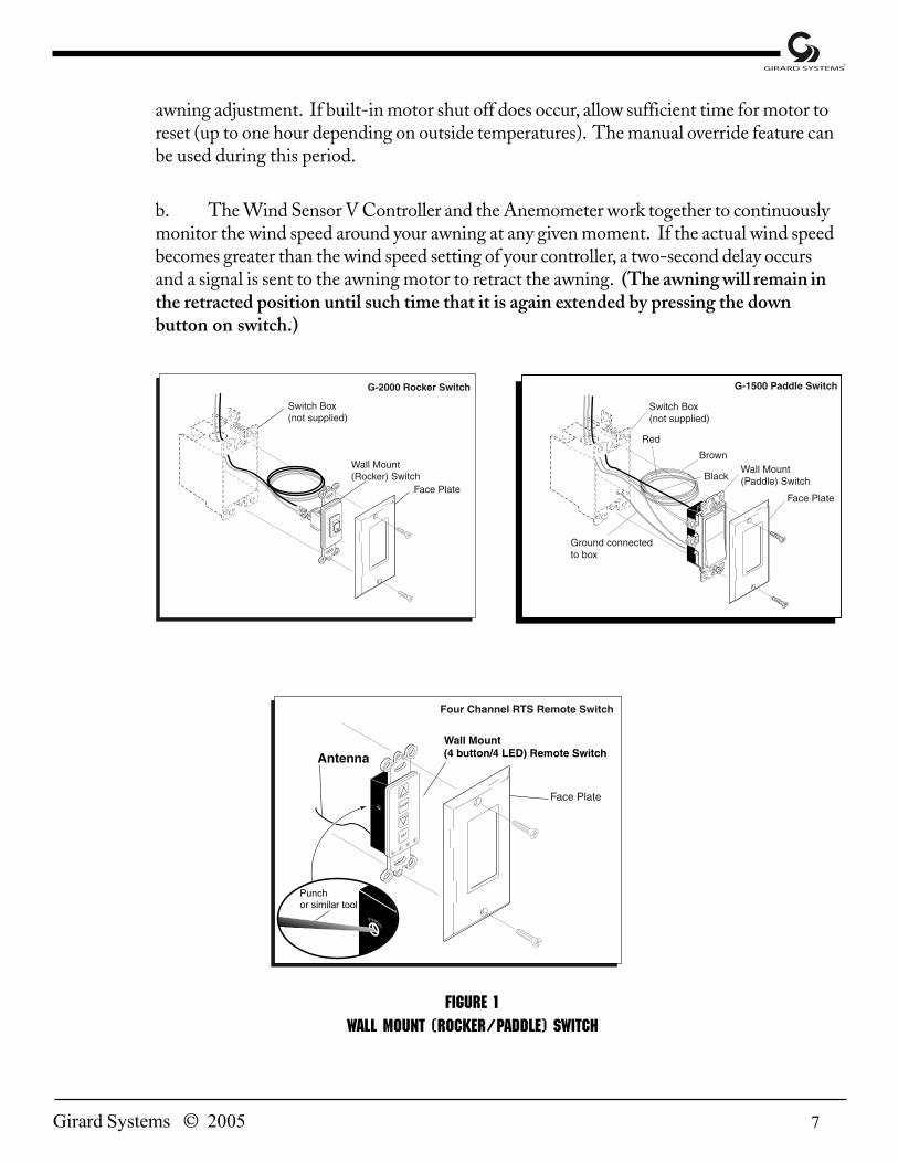
2. Using Wall Mount Rocker or Paddle Switch (See Fig. 1)
a. To extend awning, push down on rocker or paddle switch. (When fully extended,awning motor will turn off automatically. If not, refer to “Adjusting Motor Limit Switches”)
b. To retract awning, push up on rocker or paddle switch. (When fully retracted awningmotor will turn off automatically. If not refer to “Adjusting Motor Limit Switches”)
c. To stop awning at any time during extension or retraction, press opposite end ofswitch and awning will stop its progress.
3. Motor
a. The Motor supplied with your Girard G-2000 Awning and/or G-1500 Awning is ahigh torque/low RPM motor which has been carefully selcted for reliability and applicationcompatibility. It is designed for intermittent use with a rating of six (6) minutes per hour. Ifthe motor’s run-time exceeds this time period, a built-in circuit breaker will disable motorfrom operation. Generally, this condition will occur only during excessive periods of usage/
7Girard Systems © 2005
awning adjustment. If built-in motor shut off does occur, allow sufficient time for motor toreset (up to one hour depending on outside temperatures). The manual override feature canbe used during this period.
b. The Wind Sensor V Controller and the Anemometer work together to continuouslymonitor the wind speed around your awning at any given moment. If the actual wind speedbecomes greater than the wind speed setting of your controller, a two-second delay occursand a signal is sent to the awning motor to retract the awning. (The awning will remain inthe retracted position until such time that it is again extended by pressing the downbutton on switch.)
Figure 1Wall Mount (Rocker/PADDLE) Switch

8 Girard Systems © 2005
B. REMOTE CONTROL(Programming)
1. Press the Programming Button (PROG) of the receiver located in wind sensor controlbox (lower right corner) until LED lights. This indicates that for one (1) minute thereceiver is ready to receive the address of the transmitter. After this time, the LEDgoes out.
2. Press the Programming Button on the back of the transmitter (Fig. 2) with a ballpointpen until the receiver’s LED blinks. The address of the transmitter is instantlymemorized and the receiver automatically ends the programming mode.
3. To add or delete channels in receiver memory, please refer to instruction guide inremote control packaging.
4. To change battery on remote control transmitter (See repair and replace section):
Figure 2
Remote Control Transmitter

9Girard Systems © 2005
CAREC. Instructions for CARE AND CLEANING OF FABRIC
To ensure longevity of fabric quality it is highly advisable to maintain a regular regiment of simply brushingoff daily debris and dirt from fabric. To clean the awning rinse with water. In a separate bucket mix a mildsoap in water (natural soaps are best) with a clean brush dunk into the bucket and clean the awning withsweeping motions; rinse thoroughly to remove soap. If you decide to use a liquid detergent you will need toreaply a water repellent treatment, such as 303 Hi-Tech Fabric Guard or similar product. Fabric is madefrom 100% acrylic fiber. (If Fabric is non-acrylic-Soltis material use liquid detergent and water) Letfabric air dry. If you need to store your fabric, keep in a dry ventilated area.
DO NOT SUBJECT AWNING FABRIC TO EXCESSIVE HEAT as the fabric will shrink.
DO NOT STEAM PRESS OR DRY IN ELECTRIC OR GAS DRYERS, but allow to air dry.
STAIN SOLUTIONS FOR:
Fruit Stain-liquid detergent/ammonia 3-6% water
Grease(car)-volatile solvent(acetone)
Iron Rust-oxalic or citric acids, water
Mildew-1/2 cup of bleach and 1/4 cup of natural soap per gallon of water
Oil-solvent (acetone)
Paint (latex) wet-liquid detergent, water
Paint (latex) dry-Paint, oil or grease remover
Paint (oil or laquer)-paint,oil grease remover
Tree sap-turpentine, liquid detergent
Repair and replaceD. RTS Remote Switch Battery Replacement
1) Remove RTS Remote Switch following the reverse of the installation.2) Hold RTS Remote Switch by the front allowing easy access to the rear.3) Using small phillips screwdriver remove the two screws from the recessed cavities in either corner.4) Carefully remove back plate by lifting directly away from front plate (See Figure 3).5) Use standard screwdriver or similar tool to slide old battery from cradle.6) Insert new battery with fingers, and attach back plate using reverse of the removal.7) Reinstall RTS Remote Switch and recalibrate if needed.

10 Girard Systems © 2005
Figure 3rts REMOTE SWITCH BATTERY REPLACEMENT
E. REMOTE CONTROL BATTERY REPLACEMENT
To change battery on remote control transmitter (Fig. 4):
1) Remove back cover with screwdriver.
2) Slide battery out by pushing with screwdriver.
3) Insert new battery and close back cover.
Figure 4Remote Control Transmitter Battery Replacement

G-2000 Automatic Lateral Arm Awning SystemG1500 Door Lateral Arm Awning System
ADJUSTMENT/REPAIRMANUAL
WARNING: Improper installation, adjustment, alteration, service, or maintenance can causeinjury or property damage. Carefully read manual before beginning installation. Instructionssubject to change without prior notice.
San Clemente CA · Tel: (800) 382-8442 · Fax: (949) 587-9680

12 Girard Systems © 2005
GIRARD SYSTEMSG-2000/g-1500 ADJUSTMENT AND REPAIR
F. final Adjustments
Adjusting motor limit switches
Tools required
• Black plastic key provided with awning, or 4mm (5/32") Allen wrench
Procedure
The limit switches are adjusted at the factory prior to shipment. The awning motor is set to stopat the exact moment the awning box closes. (If using an ACL current-limiting device, you willhave to turn the IN limit three plus (+) revolutions past the awning’s closing point. This onlyapplies to the IN limit.) The awning motor is also set to stop at the exact moment that, whileopening, the arms lock into the extended position.
Always check the motor rotational limits after installation to assure that the awning opens andcloses correctly. Additionally, awning fabric can stretch, requiring simple adjustments.
Very important: Extreme care must be taken when setting the IN limits of the motor to ensurethat the motor turns off at exactly the same time as the awning box closes; if not, the motor willcontinue to run as it has not reached its limit. This condition, if not corrected, will substantiallyreduce motor life. Turn the awning switch OFF when awning is fully retracted. (This appliesonly to coaches older than 2000 models, unless they are compatible.)
If adjustments are required, please follow these instructions:
1. The DMI (manual override) motor has limit settings for both OUT (extension) and IN(retraction).

13Girard Systems © 2005
2. Adjust the limit switches with the black plastic key (provided) or a 4mm Allen wrench.
3. Extend the awning a few feet and locate the cylindrical awning motor mounted inside theawning roller tube (standard installation is at the right/front end of the awning). The limitswitches are mounted on the aluminum (silver) casing at the exposed end of the motor. Atthe limit switches are two black directional arrows, each with a plus (+) and a minus (-) sign.The actual limit switch is the recessed hole next to the corresponding arrow.
4. Adjust limits according to the directional arrows (see Fig. 5 callout). A 1/4 turn representsapproximately 1" of awning movement. Never set outward limits so that fabric is slack afterfull arm extension. Adjust limit switches until the motor stops at the exact time that thearms lock into position.
The diagram below refers only to motors with aluminum (silver) casings.
Figure 5
adjusting Motor limit switches

14 Girard Systems © 2005
ADJUSTING MOTOR LIMIT SWITCHES (CONTINUEd)
Procedure
After a motor has been replaced, the limit switches which control the awning’s inwardand outward stopping points must be reset. The IN switch must be set so that theawning motor stops at the exact moment the awning box closes. Likewise, the OUTlimit must be set to stop at the exact moment that, while opening, the arms lock intoposition. With a new motor the limit switches are set at mid-point; the awning will stopwith the OUT limit at approximately half-extension, and the IN limit will be set pastwhere the awning should normally close.
For a right-hand motor installation (standard), the OUT limit switch is the outermosthole, and the IN limit switch is the innermost hole. For a left-hand installation, theseswitch locations (holes) are opposite (reversed). See diagram on page 13 for reference.
Setting OUT (extend) limits
1. Extend the awning until the motor stops.
2. Locate the motor limit switches mounted inside the silver casing at the exposedend of the motor. Beside each switch is a directional arrow with a plus (+) and aminus (-) sign. The actual limit switch is the recessed hole next to thecorresponding arrow.
Setting IN (retract) limits
1. Place the awning in the IN position and allow the awning to roll up to about 6" ofbeing fully closed. Place the switch in the STOP position.
2. Locate the IN limit switch. Turn the switch in the (-) direction about twenty(20) turns.
3. Place awning switch in the OUT position and open the awning a few inches.
4. Reverse the switch direction to close the awning. (This is to ensure that the INlimit switch stops the awning before the awning is completely closed. If not,continue adjusting the IN limit switch in the (-) direction until the awning stopsbefore it is closed.)
5. Once it is correctly adjusted, place the awning switch in the IN position and turnthe IN limit switch in the (+) direction. The awning will “follow” as you turn theswitch. Continue until the awning box is approximately 3" from closing.
6. The final adjustment requires estimating the amount of awning closure per

15Girard Systems © 2005
switch rotational distance. (A 1/4 turn represents approximately 1" of awning movement.)Turn the switch the estimated amount, keeping your hand away from the box as the awningcloses. Make sure the motor does not continue to run or hum after the box is closed; if itdoes, open the awning a few inches and back the switch up in the (-) direction. Repeat thisprocedure until the motor turns off at the exact moment the awning box closes.
TestING Anemometer
1. Partially extend awning.
2. Blow or spin anemometer cups to check retraction. Awning must retract; if not, checkmotor connections for proper polarity.
adjustING Pitch angle angle
Figure 6resetting factory pre-set pitch angle
The awning comes factory pre-set with a pitch angle of approximately 20º (Fig 6), the minimumangle recommended for proper rain runoff. To increase this angle, loosen the pivot bolt located onthe outside upper joint of each arm using a 3/4" or 19mm wrench. Use the same wrench to loweror raise the pitch angle by turning the adjustment bolt clockwise to lower, counterclockwise to raise.(See Figs. 7 and 8.)

16 Girard Systems © 2005
Figure 7loosen pivot bolt
Height Adjustment of Arms
Tools Required:√ 19mm (3/4”) Open end wrench√ 10mm (3/8”) Open end wrench
This adjustment may be required if, as the awning Lead Rail closes into the awning casing, the ‘elbow’ ofone of the arms is hanging downward, hitting the bottom of the casing. This adjustment is usuallyrequired after an arm replacement
1) Open the awning about 18 inches.2) At the selected arm, loosen the (2) locknuts located at the side of the upper arm connection
using a 19mm (3/4”) open-end wrench.3) See exploded view and Figure 7. Locate the smaller adjustment bolt located directly under
the rear locknut that was just loosened. Place a 10mm (3/8”) open-end wrench around thebolt head, and rotate the wrench in a TIGHTEN (clockwise direction) to raise the arm.Slight rotation is all that is necessary; Likewise, LOOSENING (counter clockwise direction)the bolt will lower the arm. As this adjustment is being performed, keep in mind that afterre-tightening the locknuts, the arm will rise slightly higher.
4) Tighten the (2) locknuts located on the side of the arm connection.5) Close the awning completely, and check for proper fit.

17Girard Systems © 2005
Figure 8adjustment bolt
ADJUSTING LEAD RAIL
FIGURE 9PITCH OF LEAD RAIL WHEN CLOSED

18 Girard Systems © 2005
The awning lead rail comes factory pre-set with a pitch angle of +/- 3°. This angle allows the lead railto fit snugly into the main housing cover and the back housing, making a weather-resistant seal fortravel.
To increase or decrease the angle, insert a 5mm Allen wrench into the top pitch angle screw. Turnclockwise to increase the pitch, counterclockwise to decrease the pitch. (Fig 9 & 10)
FIGURE 10ADJUSTMENT OF LEAD RAIL CONNECTOR
To adjust the lead rail connector, allow it to align itself. This is done by opening awning about two(2’) feet. Remove fabric set screw on both sides. Then loosen horizontal lead rail adjustment screws.Align all elbows to ensure proper closing. Next, moderately tighten horizontal lead rail adjustmentscrews and close awning. If awning does not close correctly, open awning two (2”) inches andmoderately hit end of lead rail which is binding. Then ensure that lead rail is even on both sides.Close and then reopen awning and tighten horizontal lead rail adjustment screw and re-insert fabricset screw.
Note: Arms will reset once awning is completely enclosed.

19Girard Systems © 2005
G. Anemometer Disassembly(NOTE: This is only for new style anemometer)
1) Remove Anemometer from aluminum base following reverse of installation instructions.2) Holding cylindrical plastic base of anemometer use fingers to hold wind cups steady.3) Use 7/32 socket wrench or open end wrench to remove plastic nut from top of anemometer.4) Using gentle force pull wind cup assembly straight up off of anemometer base (See Figure 11).
CAUTION: be careful not to bend or damage brass spindle rod as this would render theanemometer useless.
5) Reassemble anemometer in reverse order using new wind cup assembly in conjunction with oldplastic anemometer base.
6) Reinstall anemometer to aluminum base.7) Recalibrate anemometer using steps described in the installation instructions.
Figure 11ANEMOMETER DISASSEMBLY
H. Instructions for replacing a motor
Procedures may vary from one vehicle to the next, for the removal and replacement of motors on theG-2000 awning. This variation, in part, is a result of different factory installation methods andpreferences on different vehicles. It may also be a result of the placement of the awning on thevehicle, i.e. accessibility of the motor. This variation primarily affects the initial accessing of themotor. Subsequent replacement operations are basically the same. These instructions address the‘accessing the motor’ as a separate category for clarification purposes. Additionally, variations in themotor style exist. The procedures are intended to be universal and inclusive of all motor types andinstallations.

20 Girard Systems © 2005
Section I accessing the motor
Beaver motor coaches: Awning is recessed into vehicle sidewall. Awning end plate is notimmediately accessible:
1) Locate the awning mounting bolts. There will be (3) sets of (6) of these, which secure theawning brackets, through to the inside of the vehicle. They are usually found inside theupper cabinets and are located directly behind the connection point of the awning arms.Only the forward set of bolts need to be accessed.
2) Loosen each bolt from the inside by removing each respective nut. Loosen the nuts onlyfrom the forward mounting bracket.
3) Using a sharp utility knife, and from outside to the vehicle, cut away 3 feet of the Siliconadhesive around the top, side, and bottom edges of the awning casing. Do this from the frontof the awning only.
4) Carefully pull the right front section of the awning casing away from the vehicle to pointwhere the entire awning end cap is accessible. Do this by either extending the awning all theway, and pulling down gently on the lead rail, this will pry awning out of the wall. Place asolid object (large flat screw driver, flat file, etc.) behind the awning casing, in front of therecess area, to hold the awning away.
5) Proceed with section II, removing the old motor.Safari motor coaches: Awning is recessed into vehicle sidewall. Awning end plate is accessiblethrough a hidden recess.
1) Locate the 2”x8” plate mounted over hidden recess directly past the front/right hand edge ofthe awning. Remove the plate by drilling out the (3) pop rivets that secure it to the vehiclesidewall.
2) Proceed with Section II, Removing the Old Motor.Surface mount installations (all other manufactures): Awning is NOT recessed into vehiclesidewall. Awning end plate is easily accessible. Section II. Removing the Old Motor.
1) Open the awning about 3 ft. If the awning is not equipped with a manual crank overrideand the awning cannot be opened, please see paragraph III below.
2) Before replacing the motor, open the awning partially and put a mark on fabric guide #4(refer to diagram on page 62) on the motor side, indication the end of the roller tube. Thisguide will have to be short end to the same length as the roller tube to fit the new motor.This can be done with a pair of tin snips.
3) Fully extend awning by manually cranking the awning out until the fabric starts to sag. Withthe awning fully extended have another person pull down on the lead rail slightly until youare able to put something behind the awning to hold it off the wall. Make sure there are nonuts on the 6 bolts that hold the awning to the wall.
4) Tape or strap each arm, about 1 ft. in from the ‘elbow’, such that the arms are locked intotheir position. These arms must be securely fixed against their own spring tension, such thatthe awning is prevented from opening further when the motor is removed. “Use this methodif awning can not be fully extended”.

21Girard Systems © 2005
5) Remove the right hand/front awning end plate by removing the (3) Phillips screw, whichsecure it to the awning casing.(Figure 12)
6) Remove both motor bolts (Figure 13,) which fasten the motor to the motor end bracketTake note and mark the slots from which the bolt were removed.
7) Loosen the small bolt by a couple of turns, which secures the motor end bracket to itsholding bracket. Do not over-loosen or attempt to remove this bolt. Slide the motor endbracket away from its holding bracket and remove.
8) Enter into the vehicle, and locate the termination point of the motor cord. This point willbe either inside junction box used for the awning switch, or will be inside the electronicbox. Either can probably be found inside of an upper cabinet. The motor cord ca beidentified as the WHITE cord bearing (4) wires. Take note of the point’s from whicheach motor wire disconnects. See also wiring diagram. Disconnect complete motor cord.
9) Tape a long ‘pig tale’ extension to the motor cord (using string, rope, small wire, etc.) suchthat when the cord is pulled through, its routing is not lost. Exit vehicle and pull motorcord completely through wall.
10) Carefully pull old motor out of awning roller tube. (Figure 13) Pull motor cord out of holein back of awning casing, and disconnect motor cord form the ‘pig tail’.
11) Locate the roller tube.
Bolt ForMotor Mount
Figure 12 Figure 13 End plate removal Removing old motor
Section IIa Removing the old motor if the awning cannot be opened and has no manualoverride.
Note: (3) people and (3) ladders will be required to perform the first portion of this procedure.
1) remove the right hand/front awning end plate and lead rail end plate by removing the (5)Phillips screws, which secure them to the awning casing.

22 Girard Systems © 2005
2) Place one person in front of the rear portion of the awning. Place a second person infront of the front potion of the awning. The third person will perform the following:Remove both motor bolts which fasten the motor to the motor end bracket (Figure 13).Take note and mark the slots from which the bolts were removed. The awning will nowbegin to extend. The first and second persons should allow the awning to extend about 3ft. At this point, each arm must be taped. Or strapped, about 1 ft. in from the ‘elbow’,such that the arms are locked into their position. These arms must be securely fixedagainst their own spring tension, such that the awning is prevented from openingfurther.
3) Proceed with step #3 of Section II. Removing the Motor.
Section III. Installing the New Motor
Note: If the new motor that is being installed is of a different type of style from that beingreplaced, please review Section IV, Motor Variations and Section V, Conversion to ManualOverride before proceeding with this section.
1) With the new motor in hand, align the notch in the black drive-disk at the far end ofmotor with the indentation in the awning roller tube. Slide motor all the way in.likewise, turn the black disk at the front of the motor such that its notch also lines upwith the indentation in the roller tube. (See Figure 13.)
2) Feed the motor cord completely through the hole in the back of the awning casing. Tapethis cord to the ‘pig tale’ that was previously brought through the cord entrance.
3) Ensure that the awning roller tube is still seated, and lodged into its end bracket at thefar end of the awning.
4) Rotate the motor and roller tube assembly such that the motor limit switches areaccessible and at an approximate 6:00 o’clock position (from right end viewing) and thatthe manual override mechanism has proper downward clearance.
5) Slide the motor end bracket back in toe awning casing and over the ‘dove tale’ connectionof its holding bracket. Tighten securely the small bolt that secures the two bracketstogether.
6) Adjust the roller tube/ motor assembly such that the threaded holes in the metal bracketof the motor line up with the (2) marked hole locations of the motor end bracket.
NOTE: Do not use center hole of motor casing to pry, to aligne, to replace motor bolts.This will cause damage to limit switches. Only pry from outer part of motor casing.
7) Insert the (2) motor bolts through the end bracket and through the threaded plate of themotor. Tighten bolts securely.
8) Replace awning end cap.9) From inside the vehicle, pull the ‘pig tale’ that was fastened to the end of the motor cord,
and feed the new motor cord all the way in.10) Wire the new motor cord as previously noted, and /or refer to either the wiring diagram
(for wind sensor operation) or the switch-wiring diagram, for direct switching to awing.11) Remove the taping or trapping forms the arms that was placed to prevent movement.
The awning will remain in that position.

23Girard Systems © 2005
12) Test for proper functioning of the new motor connections by operating the awning switch orthe wind sensor switch. The upward arrows retracts. The downward arrows extend.
13) Blow or spin anemometer cups to check for retraction (Important! Awning must retract – ifnot, check motor connections for proper polarity.)
14) After a motor has been replaced, it is extremely important that the motor limit switches beadjusted such that the motor turns off at the exact point (only if ACL current limiting deviceis not compatible) that the awning box closes. Likewise, the motor should turn off at theexact point the awning arms reach full extension and ‘click’ into place. Please see sectionentitled Adjusting Motor Limits Switches.
Section IV. Conversion to Manual Override
If a non-manual override motor is being replaced with a manual override motor, follow allprocedures as outlined in:
Section I, Accessing the Motor
Section II, Removing the Old Motor
Then – Before beginning Section III, Installing the New Motor, please complete the following:
1) Locate the fabric guide rail on the inside front of the awning casing, and slide out to theright, away form casing, 3 to 4 inches.
2) Using a hacksaw, cut off 2 inches of this fabric guide rail if the awning is surface mounted.Use tin snips to cut off the 2 inches of the fabric guide rail if the awning is recessed.
3) Slide the fabric guide rail back in completely.4) Proceed with step #1, of Section III, Installing the New Motor.AndThen:
After installing the new motor and completing steps #1 through #4, and as you are testing the motorand wiring installation in step #12, complete the following:
1) Stop the awning lead rail just before the box closes.2) The awning lead rail must have a clearance notch that will clear the manual override
mechanism, as the lead rail closes into the awning casing.3) If this hole is not present, proceed in cutting a hole 1-3/4” wide x 2” deep into the lead rail.
A plastic sleeve is available to cover the edges to this hole and can be ordered under P/N1500275-54
4) Proceed with steps #12 and #13.
IMPORTANT NOTE: CHECK FOR CORRECT FUNCIONS BY SPINNING THEANEMOMETER- AWNING MUST RETRACT WHEN ANEMOMETER IS SPUN!

24 Girard Systems © 2005
I. Fabric replacement
Recessed awnings:
This fabric changing procedure is recommended for use on G-2000 Awnings in which theawning has been ‘recessed’ into the vehicle sidewall. This is typical with both ‘Beaver’ and ‘Safari’Motor Coach installations. If the awning has not been recessed and has been ‘surface’ or ‘flush’mounted onto the vehicle side, please see ‘Fabric Replacement Method #2, Surface mountedawnings.’ In either case, the old awning fabric can be removed without the need to remove thecomplete awning, or the awning roller tube. All awning hardware will remain in position.NOTE: this procedure requires the use of the awning manual crank. If no manual crank isavailable, the motor limit switches must be used to create the settings. If this case, refer to‘Adjusting Motor Limit Switches”.
Removing the old fabric:
1) Open the awning fully until the arms ‘click’ into place. Using the manual crank, (use themotor limit switches and adjust, if no crank is available) continue to rotate the roller tubeuntil all the fabric is unrolled and the ‘C’ groove of the roller tube is accessible.
2) Remove the (4) four fabric set screws (two are located on the lead rail and two are located onthe roller tube. see Figure 14 & 15)
3) Remove the left hand lead rail end cap. Shift the fabric from the roller tube ‘C’ groove bysliding it along to the left hand end of the tube. At this point the white poly rope should beaccessible from the end of the fabric and roller tube.
4) Using a screwdriver, bend the Poly rope down and outward such that it can be gripped witha pair of pliers. Pull the poly rope completely out of the roller tube.
5) The remaining fabric will now be free and fall from the roller tube.6) Slide the old fabric out of the left hand side of the lead rail.7) Preserve the Poly rope that was removed from the fabric at the roller tube.
Poly Rope
Main Housing
End Plate
Screw ForEnd Plate
Roller Tube
Some pieces not shown for clarity
Fabric Set Screw
End Plate ForLead Rail
Screw For End Plate
Poly Rope
Fabric Set Screw
Some pieces not shown for clarity
Figure 14 Figure 15 Removal of end plate (lfeft Side) Removal of Face plate and poly rope

25Girard Systems © 2005
Instalation of new fabric
IMPORTANT NOTE: Replacement fabrics are shipped in a rolled condition. The front edge of thefabric will be marked ‘lead rail end-up’, and will be the leading edge of the roll as you receive it. Thehems will always face downward as the fabric is installed. The other end of this fabric will havemounted, inside of the hem, a small Poly rope. This end will be mounted into the roller tube. The Polyrope that was removed from the old fabric at the roller tube will get used for this installation.
1) Tape the sharp edges of the ‘C’ channel (fabric channel) of the lead rail such that the fabric willslide and enter freely without snagging or tearing.
2) Slide the white Poly rope, that was removed from the old fabric, completely into the open, fronthem of the new fabric (marked Lead Rail). The second Poly rope form the old fabric will not beused in this installation).
3) The new fabric will need to be unrolled and inserted into both the lead rail, and the roller tube atthe same time. This is done in small even increments about 1-2 feet per pull. You will have tomanipulate the fabric into the roller tube, as it will be a tight squeeze to fit the fabric in becausethe limited space to work with. Insert carefully as to not snag or tear fabric. Ensure that theseams are facing downward. Continue until entire length of fabric has been fed into both rollertube and lead rail.
4) Slide the fabric back and forth inside the roller tube to assure the entire length of hem has beenproperly inserted. Center the fabric on the roller tube, and square up fabric assembly at lead rail,i.e., remove wrinkles. Insert self taping screws on both ends of the fabric into roller tube. Thefabric will self-center on the leader rail.
5) Slowly begin to roll the fabric up, onto the roller tube, using the manual crank. (The motor limitswitches will have to be used, and adjusted if no manual crank is available). Roll the fabric fromthe bottom of the roller tube. (See Figure 14)
6) Using two people, carefully stretch the fabric from end to end during the first few revolutions ofthe roller tube, to assure the fabric is rolling straight and true. Continue to slowly roll the fabriconto the tube until the fabric is taught and in its ‘full extension’ mode against the locked, fullyextended arms. Continue to roll the fabric in, this time using the awning switch and motor.Watch carefully to assure the fabric rolls straight, and close the awning completely.
7) Once again, open awning about 18 inches. Pull the leading edge if the fabric taught, from bothends, and replace both fabric set screws. Note: These screws should be located No Further than¾” from the edge of the fabric. Re-drill fabric set screw holes. If necessary with a 1/8” dia. drillbit, to maintain this distance.
8) Replace lead rail end cap.9) After a fabric replacement, it may be necessary to make minor adjustments to the motor limits
switches to assure that the awning motor stops exactly when the box closes (unless using ACLcurrant limiting device. Likewise, it is important that the awning motor stops exactly when theawning is extending and the arms ‘snap’ into their full extension position. Please see ‘AdjustingMotor Limit Switches’
Important Note: The high torque motor which is supplied with the G-2000 awning is designed torun 4 minutes/hour. The motor has a built-in circuit breaker which is designed to activate if themotor overheats. The cool down time can be to 1 hour, depending on outside temperature.
26 Girard Systems © 2005
During this fabric installation and adjustment process, please use the power of the motor sparingly,as to not create an overheat condition.
Fabric replacement – procedure #2, surface mounted awnings:
This fabric changing procedure is recommended for use on G-2000 awnings in which the awning hasbeen ‘surface’ or ‘flush’ mounted to the vehicle side wall.’ If the awning has been ‘recessed’ into thevehicle side, please see ‘fabric replacement method #1, recessed awnings’. In either case, the old awningfabric can be removed without the need to remove the complete awning, or the awning roller tube. Allawning hardware will remain in position. NOTE: Both procedures require the use of the awningmanual crank in portion. If no manual crank is available, the motor limit switches must be used tocreate the settings. If this is the case, see ‘Adjusting Motor Limits Switches’.
Removing the old fabric:
1) Open the awning fully until the arms ‘click’ into place. Using the manual crank, (use the motor limitswitches and adjust, if no crank is available) continue to rotate the roller tube until all the fabric isunrolled and the ‘C’ groove of the roller tube is accessible.
2) Remove the (4) four fabric set screws (two are located on lead rail two are on the roller tube.)3) Remove both lead rail end caps and awning end caps. (See Figure 14 and 15) Using two people,
carefully slide the entire fabric out from the left end of the roller tube (make sure the Poly rope clears thesupport bracket for the roller tube) and from the end of the lead rail. Remove both Poly ropes form theforward and rear hems of the old fabric. This will be used on the new fabric installation.
Instructions of new fabric
IMPORTANT NOTE: Replacement fabrics are shipped in a rolled condition. The front edge of thefabric will be marked ‘lead rail end-up’, and will be the leading edge of the roll as you receive it. Thehems will always face downward as the fabric is installed. The other end of this fabric will havemounted, inside of the hem, a small Poly rope and discard.
1) Insert one of the (2) larger Poly ropes (that was removed form the old fabric) into the front hemof the new fabric. Carefully unroll the new fabric, and insert the second larger Poly rope (thatwas also removed from the old fabric) into the rear hem of the new fabric. This end will bemounted into the roller tube.
2) Tape the sharp edges of the ‘C’ channel (fabric channel) of the lead rail such that the fabric willslide and enter freely without snagging or tearing. Tape also all sharp edges of the awning casingand the roller tube support bracket.
3) Insert the leading edges of the new fabric into the fabric grooves of both the left ends of the leadrail and the roller tube. This function is most safely and easily performed with four people.Carefully slide the new fabric down both the lead rail and roller tube simultaneously. Twopeople can pull the front of the fabric, as two people are holding the excess fabric and feeding the

27Girard Systems © 2005
rear of the fabric into the roller tube and lead rail.4) Center the fabric on the roller tube, and square up fabric assembly at lead rail, i.e., remove
wrinkles. The fabric will self-center on the lead rail. Insert self taping screws on both ends of thefabric into roller tube (see Figure 14)
5) Slowly begin to roll the fabric up, onto the roller tube, using the manual crank. (The motorlimit switches will have to be used, and adjusted of no manual crank is available). Roll thefabric from the bottom of the roller tube.
6) Using two people, carefully stretch the fabric from end to end during the first few revolutions ofthe roller tube, to assure the fabric is rolling straight and true. Continue to slowly roll the fabriconto the tube until the fabric is taught and in its ‘full extension’ mode against the locked, fullyextended arms. Continue to roll the fabric in, this time using the awning switch and motor.Watch carefully to assure the fabric rolls straight, and close the awning completely.
7) Once again, open awning about 18 inches. Pull the leading edge if the fabric taught, from bothends, and replace both fabric set screws. Note: These screws should be located No Further than¾” from the edge of the fabric. Re-drill fabric set screw holes. If necessary with a 1/8” dia. drillbit, to maintain this distance.
8) Replace lead rail end cap.9) After a fabric replacement, it may be necessary to make minor adjustments to the motor limits
switches to assure that the awning motor stops exactly when the box closes (unless using ACLcurrant limiting device. Likewise, it is important that the awning motor stops exactly when theawning is extending and the arms ‘snap’ into their full extension position. Please see ‘AdjustingMotor Limit Switches’
Important Note: The high torque motor which is supplied with the G-2000 awning is designed torun 4 minutes/hour. The motor has a built-in circuit breaker which is designed to activate if themotor overheats. The cool down time can be to 1 hour, depending on outside temperature.During this fabric installation and adjustment process, please use the power of the motor sparingly,as to not create an overheat condition.
J. Replacing a damaged arm
Tools Required:
√ 19mm (3/4”) Open end Wrench
√ 5 mm (3/16”) Allen Wrench
This procedure should be followed when one or more of the hinging, spring loaded arms needsto be replaced. There are no repairable parts inside of these arms, therefore, if the ‘elbow’ jointof the arm has broken, the entire arm should be replace.

28 Girard Systems © 2005
Important Note: Extreme CAUTION should be used when working with these arms. Theyare under heavy spring tension. As replacement parts, they are shipped in a folded and bandedcondition. Always use two people to un-tape and unfold each arm. Arms should always behandled and installed in the folded condition until ready to fasten to lead rail.
1) Slowly and carefully open the awning a few feet. If the elbow of the arm in question is broken,place a large rag of cloth around this elbow. Pay particular attention to the arm that is broken, asit may have to be (away form the awning fabric).
2) Cut stainless steel cable at elbow to release tension than proceed with arm removal otherwiseremove 17mm nut at lead rail connection disconnect arm and fold and tape it folded being varycarefully because arm is still under tension.
3) At the front of the arm to be removed; at the lead rail, remove the 17 mm nut and washer andretain these parts for the new arm.
4) At the upper end of the arm, at the awning casing, remove both lock nuts and washers or the boltand nut.
5) Remove the forward most bolt form the arm and shoulder connection. Use this bolt for the newarm installation if this bolt was not provided with the new arm. Hold the bottom pitchadjustment bolt.
6) Into position with a 19mm (3/4”) open end wrench, and proceed by carefully sliding the armand remaining bolt away from the shoulder.
7) Do not un-band new arm until fastened to shoulder in awning casing.

29Girard Systems © 2005
8) If the arm you are replacing has a fixed bolt insert the arm into the shoulder ensuring that thefixed bolt on the arm goes through the pitch adjustment assembly, through the square tube, andthough the washer, which are components inside the shoulder. Insert the front, loose bolt andnut.If the arm you are replacing does not have a fixed bolt use the bolt supplied with the arm toslide through the square tube for the shoulder support then through the pitch adjust assemblyand into the arm connection plate. Insert the front, loose bolt and nut.
9) Proceed with un-banding arm very carefully as this arm is under heavy tension than fasten tolead rail refer to #8 procedure.
10) Attach the front of the arm to its connection point at the lead rail by replacing the pivot pin fromthe top, and securing it with the retaining ring of exploded view). Then slide into the lead railconnection and replace the nut and washer. Tighten both lock nuts, one turn from being tight, atthe upper end of the arm. Adjust the pitch angle of the arm to match the other arms by rotatingthe head of the pitch adjustment screw. Rotate this screw in a clockwise direction (looking formthe bottom up) to lower the arm. Likewise, rotating this screw in a counter clockwise directionwill raise the arm. Tighten both lock nuts. See also; adjusting the Pitch Angle, in the‘Adjustment’ section of this manual (Figure 16).
Figure 16
Parts BreakDown of Lateral Arm

G-2000 Automatic Lateral Arm Awning SystemG1500 Door Lateral Arm Awning System
INSTALLATIONMANUAL
WARNING: Improper installation, adjustment, alteration, service, or maintenance can causeinjury or property damage. Carefully read manual before beginning installation. Instructionssubject to change without prior notice.
San Clemente CA · Tel: (800) 382-8442 · Fax: (949) 587-9680

31Girard Systems © 2005
product descriptionThe G-2000 Automatic Lateral Arm Awning System provides perfect weather protection at thetouch of a button. Powered by a single motor control, your unit features the wind sensor controlbox, the wind sensor anemometer, an attractive one-button wall mount switch which operates likea garage door opener, ten feet (10') of low-voltage cabling, and includes an integrated radio receiverplus a hand-held remote transmitter/control (see below). With the addition of the Wind Sensor Vwith Remote to your awning installation, wind speeds will be continuously monitored, triggeringthe controls to retract the awning in event of winds above 22 mph. The control box is packaged in aweatherproof enclosure and includes watertight strain-relief fittings for wires entering the box.Installation is quick and easy and includes all necessary cabling. The Wind Sensor V with Remoteuses a hand-held radio transmitter which features up, down, and stop buttons.
The G-1500 Door System is a shorter version of the G-2000 Automatic Lateral Arm Awning System.
INDEPENDENT Components

32 Girard Systems © 2005
TOOLS REQUIRED
√ Electric drill; 1/8", 5/16", 7/16" drill bits (for pilot hole - 1/8" x 8" long)
√ Open-ended wrenches: 10mm, 17mm, and 19mm
√ Allen wrenches: 4mm and 5mm
√ Socket wrench (7/16" deep socket)
√ Measuring tape
√ Snap (chalk ) line
√ Phillips screwdriver
√ Flathead screwdriver (small)
√ Keyhole saw
√ Two (2) tubes silicone
√ Two (2) ladders
ALL ELECTRICAL WORK MUST CONFORM TOAPPLICABLE ELECTRICAL CODES AND STANDARDS
Turn off power before beginning electrical work.
Refer to your RV’s wiring diagram for placement of existing wires before drillingor beginning awning installation.
Be sure that placement of controls, cables, and/or wires does not impede, crimp,or otherwise obstruct continuity of electrical current.
Prior to beginning installation sequence and while awning is on the ground, open awning approximatelyeight inches (8") using hand crank to confirm awning arm location. (See Fig. 17)
Important Note: When proceeding to Section K, note that each awning arm must have a wall mountbracket directly behind it for proper mounting.
33Girard Systems © 2005
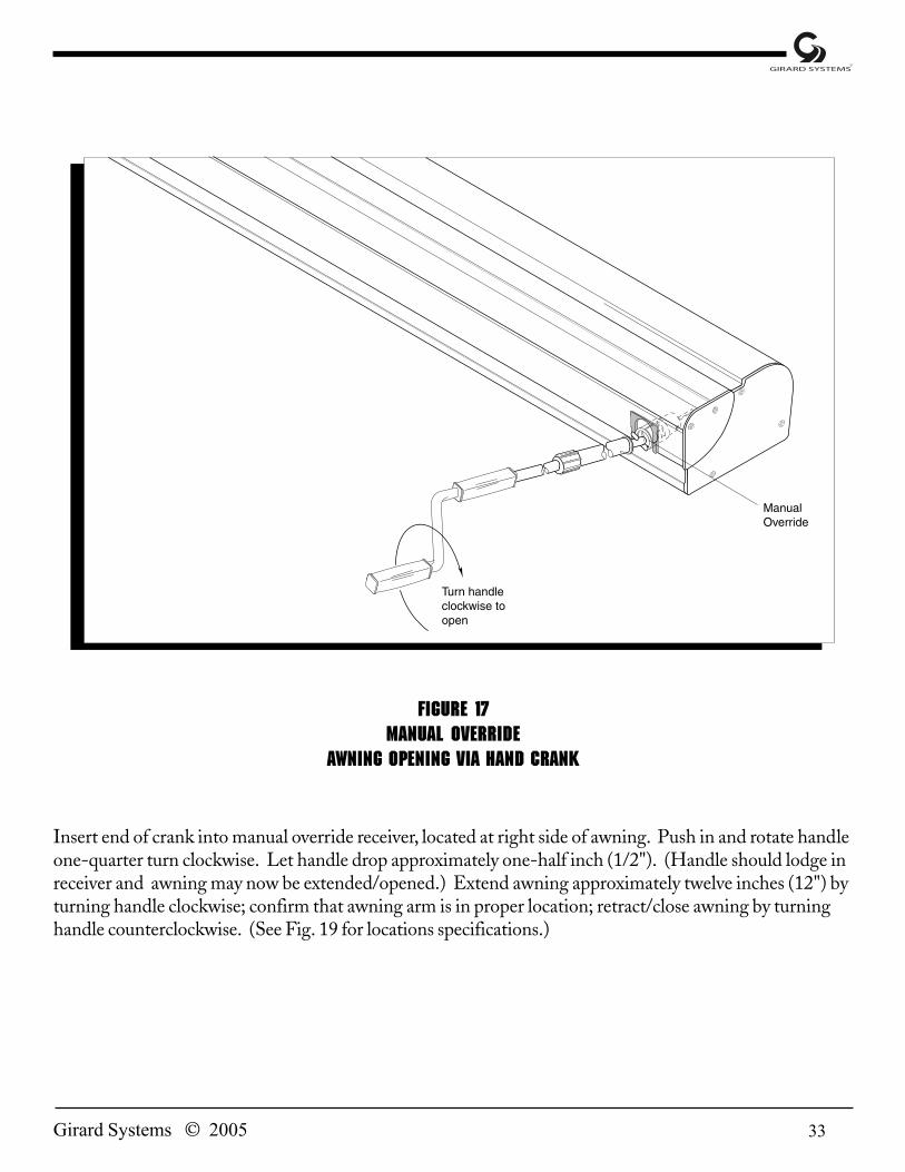
Figure 17Manual Override
Awning Opening via Hand Crank
Insert end of crank into manual override receiver, located at right side of awning. Push in and rotate handleone-quarter turn clockwise. Let handle drop approximately one-half inch (1/2"). (Handle should lodge inreceiver and awning may now be extended/opened.) Extend awning approximately twelve inches (12") byturning handle clockwise; confirm that awning arm is in proper location; retract/close awning by turninghandle counterclockwise. (See Fig. 19 for locations specifications.)

34 Girard Systems © 2005
INSTALLATION SEQUENCE4.5 hours (based on two installers)
K. RV WALL MOUNT BRACKETS
1. Wall mount brackets have been assembled to awning for shipping purposes. (See Fig. 19 forquantities.)
2. Remove the three (3) brackets from back of awning using a 5mm Allen wrench to loosen theset screws (one on the bottom of each bracket). (See Fig. 18).
Figure 18
Slide Lock Removal from Bracket

35Girard Systems © 2005

36 Girard Systems © 2005
Figure 20G-1500 Bracket Positioning
3. Move slide locks along awning channel until they clear brackets. The brackets will thenrelease and can be removed from awning.
4. Using brackets as templates, measure and mark bracket hole locations so placement lies:
a. directly behind arm locations of awning casing; and
b. parallel to vehicle body features, as high as possible on vehicle (not less than 5/8" frombottom of drip rail) so awning lip will clear (Fig. 19 or Fig. 20).
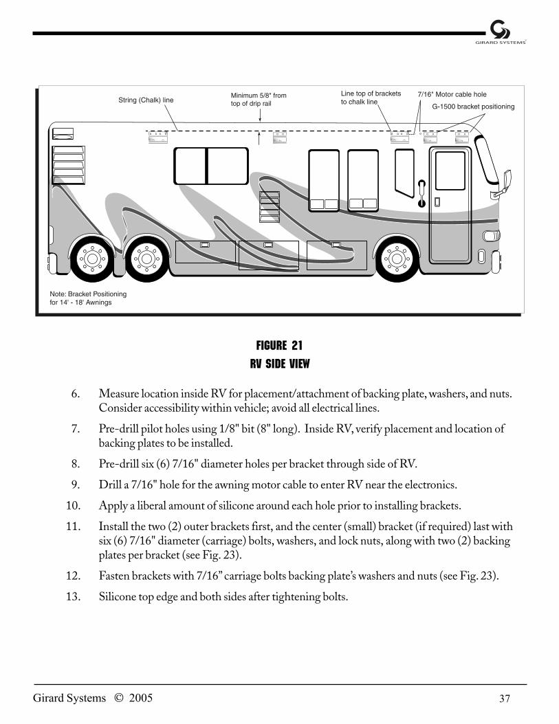
5. Snap a string (chalk) line along the side of the vehicle to ensure horizontal accuracy of themounting brackets. Minimum 5/8" from bottom of the drip rail (Fig. 21).
37Girard Systems © 2005
Figure 21RV Side View
6. Measure location inside RV for placement/attachment of backing plate, washers, and nuts.Consider accessibility within vehicle; avoid all electrical lines.
7. Pre-drill pilot holes using 1/8" bit (8" long). Inside RV, verify placement and location ofbacking plates to be installed.
8. Pre-drill six (6) 7/16" diameter holes per bracket through side of RV.
9. Drill a 7/16" hole for the awning motor cable to enter RV near the electronics.
10. Apply a liberal amount of silicone around each hole prior to installing brackets.
11. Install the two (2) outer brackets first, and the center (small) bracket (if required) last withsix (6) 7/16" diameter (carriage) bolts, washers, and lock nuts, along with two (2) backingplates per bracket (see Fig. 23).
12. Fasten brackets with 7/16” carriage bolts backing plate’s washers and nuts (see Fig. 23).
13. Silicone top edge and both sides after tightening bolts.

38 Girard Systems © 2005
Figure 23Mounting Bracket and Backing Plate
View from RV – Inside to Outside
L. MOUNTING AWNING TO WALL MOUNT BRACKETS
1. Lift awning into position for placement onto brackets.
a. While ladders are generally sufficient, you may use a scaffold or a forklift to raiseawning into position (Fig. 24).
b. If using forklift, lift from center line of awning (“CL” on Fig. 24) to maintain productbalance while elevating.

39Girard Systems © 2005
figure 24MOUNTING AWNING TO WALL MOUNT BRACKETS

40 Girard Systems © 2005
2. Place awning onto brackets, ensuring the two (2) grooves in back of awning fall over the two(2) lips on brackets (Fig. 25) while feeding awning motor cable through previously drilledhole.
3. Seal motor wire with silicone.
4. Secure awning by moving slide locks (moved in step A-3) along bottom awning track untilcentered under respective brackets, directly below arm connection.
figure 25awning – end view
5. Tighten set screws into slide lock of each mounting bracket.

41Girard Systems © 2005
M. ANEMOMETER(Hardware Installation Only)
1. Place anemometer on roof of vehicle in position shown (Fig. 26), ensuring that base ispointing toward front of RV. Location should be
a. on and parallel to roofline of RV; and
b. near awning to ensure wind speed is measured at the awning. Guard againstinstalling anemometer near obstructions (air conditioner, storage pod, etc.).
2. Mark a hole location for cord insertion into RV, with placement directly below where cordexits bottom of anemometer.
Figure 26Anemometer (Wind Sensor) Placement on Roof of RV
42 Girard Systems © 2005
3. Drill one 3/8" hole for anemometer wire.
4. Pull anemometer cord back through original packaging hole until cord dangles straight downfrom exit point of anemometer body (see Fig. 26).
5. Seal original packaging hole with silicone.
6. Feed anemometer cord (containing blue and brown wires) through hole in roof, leaving threeto four inches (3–4") of slack, and secure anemometer with sheet metal screws.
7. Seal top footprint of anemometer after securing it to roof.
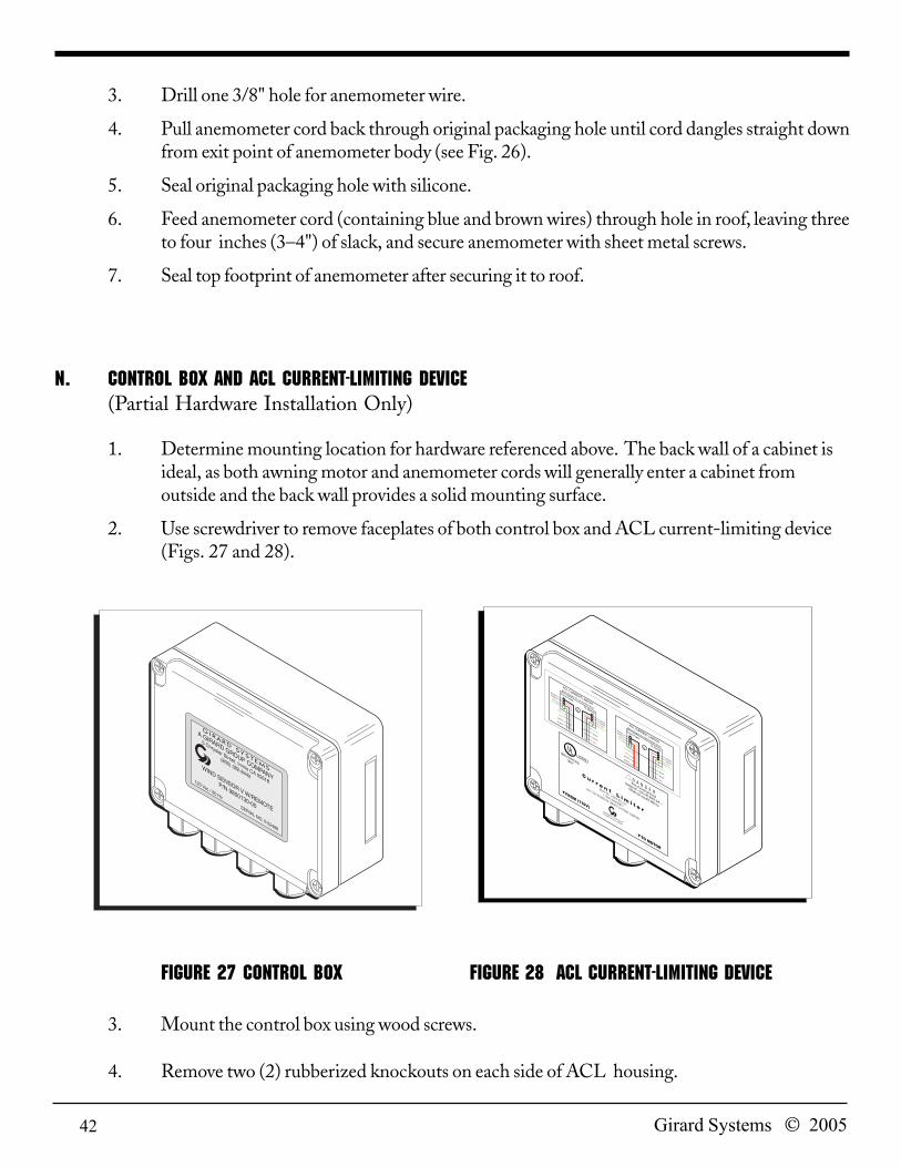
N. CONTROL BOX and ACL CURRENT-LIMITING DEVICE(Partial Hardware Installation Only)
1. Determine mounting location for hardware referenced above. The back wall of a cabinet isideal, as both awning motor and anemometer cords will generally enter a cabinet fromoutside and the back wall provides a solid mounting surface.
2. Use screwdriver to remove faceplates of both control box and ACL current-limiting device(Figs. 27 and 28).
Figure 27 control box Figure 28 ACL current-limiting device
3. Mount the control box using wood screws.
4. Remove two (2) rubberized knockouts on each side of ACL housing.
43Girard Systems © 2005
5. Use screws to mount the ACL current-limiting device BELOW control box.
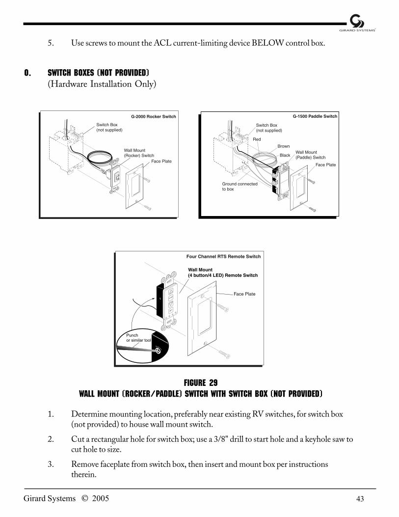
O. switch boxes (not provided)(Hardware Installation Only)
Figure 29Wall Mount (Rocker/PADDLE) Switch with Switch Box (not provided)
1. Determine mounting location, preferably near existing RV switches, for switch box(not provided) to house wall mount switch.
2. Cut a rectangular hole for switch box; use a 3/8" drill to start hole and a keyhole saw tocut hole to size.
3. Remove faceplate from switch box, then insert and mount box per instructionstherein.

44 Girard Systems © 2005
4. Ten feet (10') of gray low-voltage cable (black and red wires within) is provided to makeconnection with wall mount switch. Connect black and red wires as follows:
a. Hold wall mount rocker switch in vertical (up and down) position with black dot atbottom.
b. Hold wall mount paddle switch in vertical (up and down) position with the groundscrew on the bottom left-hand side.
c. Rotate wall mount switch to reverse side (still in vertical position) and connect cablewires, black above red, to the two terminals on back of switch.
5. Install wall mount switch into switch box from front (pulling wiring through to back) usingscrews provided.
6. Install switch box faceplate using screws provided.
P. g-1500 WALL MOUNT (paddle) SWITCH(Electrical Installation)
1. Run wall mount paddle switch cable wiring from switch box to junction box.
a. Insert all the wires through wiring guide holes at bottom of junction box.
b. Connect wires as follows:
1) Brown wire (B1): from paddle switch to black wire from Somfy motor.
2) Red wire (A1): from switch to red wire from Somfy motor.
3) Black wire (L1): from paddle switch to black wire from main power source.
4) White wire: from Somfy motor to white wire from main power source.
5) Green ground wires (3): connect wires from switch box, Somfy motor, and mainpower source to each other, ground to junction box, and then secure all connectionswith pigtail.
(See Wiring Diagram, Fig. 31)

45Girard Systems © 2005
Figur
e 30
G-20
00 A
utom
atic
lat
eral
arm
awn
ing
syst
em w
irin
g di
agra
m

46 Girard Systems © 2005
Figure 31 g-1500 door awning wiring diagram
P. g-2000 WALL MOUNT (rOCKER) SWITCH(Electrical Installation)
1. Run wall mount switch cable wiring from switch box to control box:
a. Insert black and red wires through wiring guide holes at bottom of control box.
b. Connect wires to first and third terminals (counting from bottom to top) in controlbox, located just to the right of “Low Voltage Switch” label (see bottom center portionof Wiring Diagram, Fig. 30).
P. REMOTE SWITCH(Hardware Installation)
1. Determine mounting location out of reach of small children or accidental contact. Be surethere is no wiring behind mounting screws.
a. Place remote control mounting bracket/cradle into position and mountusing screws and anchors provided (Fig. 34).
P. Remote motor(Electrical Installation)

47Girard Systems © 2005
1. Insert all the wires through wiring guide holes at the bottom of branch box.
2. Connect wires as follows:a. Black wire (L1): from motor to black wire form main power source.b. White wire: from motor to white wire from main power source.c. Green ground wires (3): connect wiresfrom branch box, motor and main power source to
each other, ground to branch box and then secure all connections.(see bottom center portion of Wiring Diagram, Fig. 32).
Figure 32 Remote motor wiring diagram
Hz Operator wiring
NOTE: All electrical work must comply to all Rvia codes and national electrical codes.
1. It is recommended that provisions be made to cut power individually when wiring Hzoperators.
(((((This cThis cThis cThis cThis can be in the foran be in the foran be in the foran be in the foran be in the form ofm ofm ofm ofm of an in-line OFF/ON switc an in-line OFF/ON switc an in-line OFF/ON switc an in-line OFF/ON switc an in-line OFF/ON switch.h.h.h.h. The abilitThe abilitThe abilitThe abilitThe ability to cut the powy to cut the powy to cut the powy to cut the powy to cut the poweeeeer to ear to ear to ear to ear to eaccccch motorh motorh motorh motorh motorindiindiindiindiindividually is rvidually is rvidually is rvidually is rvidually is requirequirequirequirequired to easily pred to easily pred to easily pred to easily pred to easily progogogogogrrrrram the motor).am the motor).am the motor).am the motor).am the motor).
NOTE: Wiring Diagram of the G-2000 is referred to throughout balance of Installation Manual.

48 Girard Systems © 2005
2. While cover is off control box, take specific note of wind speed setting (Fig. 33 callout,“Wind Adjustment”). The arrow should be pointing at the 3:00 position (factory pre-set at22 mph). To adjust the pre-set wind speed, rotate the dial to the preferred setting. Theminimum setting is 12 mph; maximum setting is 31 mph.GIRARD SYSTEMS STRONGLY RECOMMENDS NOT SETTING THE DIALOVER 26 MPH. DISREGARDING THIS WARNING MAY VOID WARRANTY.
Figure 33Control Box (Internal) with Wind Speed Setting Dial
Q. AWNING MOTOR CORD and ACL-6 CURRENT-LIMITING DEVICE(Electrical Installation)
1. Take end of awning motor cord wire(s) and cut off a portion long enough to connect the

49Girard Systems © 2005
ACL current-limiting device and the control box.
2. Use remaining motor cord wiring to connect to ACL device (see Wiring Diagram, Fig. 30).Feed motor cord wires (white, red, black, and green) through one of ACL knockout holes andconnect to red block with respective color to the input terminals.
3. Connect cut-off portion of awning motor cord to brown block ACL device as shown onWiring Diagram.
4. Using other end of cut-off portion, connect wires from ACL device through wiring guideholes to control box as shown on Wiring Diagram.
5. Motor must be wired to come on when anemometer is activated. See Section M for testinginstructions.
R. ANEMOMETER(Electrical Installation)
1. With anemometer cord already fed into RV, insert anemometer wires (blue and brown)through wiring guide holes at bottom of control box and connect as shown on WiringDiagram (Fig. 30).
S. 1 motor 1 remote control/wireless switch (Initial Programming)
1. The Motor will be in “Factory Mode” right out of the box when power is connected. Toprepare the motor for programming, press the transmitter UP and DOWN buttonssimultaneously until motor jogs forward and back.
2. Hold the transmitter within 10 feet of the motor and press the Up button. If the motorrotates in the Up direction, move to step 4 programming.
3. If the motor, goes down instead of up, press and hold the stop button until the motorbounces forward and back. Confirm the UP button now makes the awning go up.
4. Hold the transmitter within 10 feet of the motor head, Press and hold the program button(about 1 second) until the motor jogs forward and then back. Transmitter Range will now beapproximately 100 feet.
5. You can now proceed to the up and down limit settings
T. Multible Motors - 1 remote control/wireless switch(Initial Programming)
Successful programming is accomplished by programming one awning at a time. To prevent error youmust make sure that the power is OFF to all previously programmed awnings; before moving to the next.

50 Girard Systems © 2005
NOTE: Before moving to the next awning disconnect power to each previously programmed awing.
1. Turn power ON to the first awning you wish to program.
2. Make sure you have both the remote control and wireless switch in hand.
3. Using remote control, press the gray channel selector to set sequence. (i.e., first awningshould be indicated by the first light, second awning by second light etc.). Thecorresponding LED light will blink for three (3) seconds indication channel.
4. Press the transmitter UP and DOWN buttons simultaneously until the motor jogs forwardand back.
5. Hold the remote within ten feet of the motor and press the UP button. If the awning movesin the UP direction move to step 7.
6. If the awning goes down instead of UP, press and hold the stop button until the motor jogs.Confirm the UP button now makes the awning retracts.
7. Using the remote control confirm you are on the proper channel then press and hold theprogram button on the back of the remote. Awning will jog indicating correctprogramming.
8. Select the channel you just programmed with the remote control. Press and hold theprogram button on the back to the remote control again – until motor jogs. Immediately findthe same channel on your wireless switch using the set button. Then push and hold programbutton on the side of the wireless switch. Motor will jog confirming programming.
9. Select the channel you just programmed with the remote control. Again press and hold theprogram button on the back of the remote control until the awning jogs.
10. Select the ALL Channel the remote control (all LED’s light up). Press and hold the programbutton on the back to the remote control. Awning will jog confirming group operation.
11. Repeat steps 9-10 using the wireless switch.
12. The remote control and wireless switch are now programmed for individual or groupcontrol.

51Girard Systems © 2005
Figure 34Remote Control Transmitter
U. MAIN POWER SOURCE(Electrical Installation)
1. Wire main vehicle power into control box as shown on Wiring Diagram (wiring notprovided).
2. Turn on main power.
V. REMOTE CONTROL(Initial Programming)
1. Press the Programming Button (PROG) of the receiver located in control box (see Fig.34, lower right corner) until LED lights. This indicates that for one (1) minute thereceiver is ready to receive the address of the transmitter. After this time, the LED goesout.
2. Press the Programming Button on the back of the transmitter (Fig. 34) with a ballpointpen until the receiver’s LED blinks. The address of the transmitter is instantlymemorized and the receiver automatically ends the programming mode.
3. To add or delete channels in receiver memory, please refer to instruction guide in remotecontrol packaging.

52 Girard Systems © 2005
W. WEATHER STRIPPING(Installation) Note: This installation does not apply to awnings inset into the vehicle side.
1. Trim weather stripping to length of awning. To achieve optimum aerodynamics,do not allow any overhang of weather stripping.
2. Make small cut in weather stripping so it fits around awning motor cord.
3. Apply generous beads of silicone where indicated in (Fig. 35).
4. Push firmly into place.
Figure 35WEATHER STRIPPING

53Girard Systems © 2005
SPECIFICATION SHEETG-2000/g-1500
Figure 36 Figure 37
g-2000 Awning case Dimensions (External) g-1500 Awning case Dimensions (External)
I. AWNING CASE1. Height
a. 7-3/8" at mounting pointb 7-3/4" at front
2. Widtha. 5-1/4"
3. G-2000 Weight G-1500 Weighta. 12'0" Awning - 116 lbs. a. 4'8" Awning -40 lbs.b. 18'0" Awning - 172 lbs. b. 6'0" Awning -55 lbs.c. 19'8" Awning - 188 lbs. c. 8'0" Awning -70 lbs.d. 21'8" Awning - 208 lbs. d. 10'0" Awning - 85 lbs.e. 22’11” Awning - 220lbs. e. 12'0" Awning -95 lbs.
4. Fabrica. 100% Woven Acrylic
II. ROLLER TUBE1. Diameter - 3"

54 Girard Systems © 2005
III. MOTOR SPECIFICATIONS1. Type - Tubular with Manual Override2. 120 VAC - 60 Hz3. 12 RPM - 4-minute Maximum Run Time4. 2 Amps - 240 Watts5. 50 Nm6. Thermal Protected
IV. MOUNTING BRACKETS1. Height - 7-5/16"2. Width
a. Outer Brackets - 19-1/2"b. Center Bracket - 11-1/2" (over 18')c. Center Bracket - 4" (14'–18')
V. CORD/CABLE LENGTHS1. Awning Motor - Six (6') foot cord2. Wind Sensor Anemometer - Six foot (6') cord3. Wall Mount Rocker Switch (G-2000) - Ten foot (10') low-voltage cable4. Wall Mount Paddle Switch (G-1500) - Ten foot (10') 120V/15amp cable
VI. CONTROL BOX SPECIFICATIONS1. Input: 120 VAC - 50/60 Hz2. Output: 120 VAC - 50/60 Hz; 1 phase; 3.0 FLA; 0.1 HP
VII. REMOTE CONTROL TRANSMITTER1. Single Frequency - 433 Mhz2. Lithium Battery - 12V/23amp3. Frequency Range - 45 ft.
VIII. REMOTE RTS switch1. Single Frequency - 433 Mhz2. 3V Lithium Battery - 12V/23amp3. Frequency Range - 65 ft.
55Girard Systems © 2005
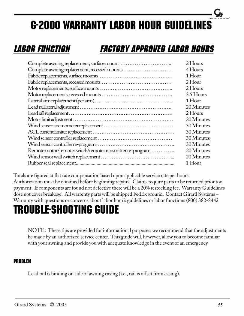
G-2000 Warranty Labor Hour Guidelines
LABOR FUNCTION FACTORY APPrOVED LABOR HOURSComplete awning replacement, surface mount ……………………….. 2 HoursComplete awning replacement, recessed mounts ……………………… 4 HoursFabric replacements, surface mounts ………………………………….. 1 HourFabric replacements, recessed mounts ………………………………… 2 HourMotor replacements, surface mounts ………………………………….. 2 HoursMotor replacements, recessed mounts …………………………………. 3.5 HoursLateral arm replacement (per arm) …………………………………….. 1 HourLead rail lateral adjustment ……………………………………………. 20 MinutesLead rail replacement ………………………………………………….. 2 HoursMotor limit adjustment ………………………………………………… 20 MinutesWind sensor anemometer replacement ………………………………… 30 MinutesACL current limiter replacement ………………………………………. 30 MinutesWind sensor controller replacement …………………………………… 30 MinutesWind sensor controller re-programs ……………………………………. 30 MinutesRemote motor/remote switch/remote transmitter re-program…………. 20 MinutesWind sensor wall switch replacement …………………………………... 20 MinutesRubber seal replacement................................................................................. 1 Hour
Totals are figured at flat rate compensation based upon applicable service rate per hours.Authorization must be obtained before beginning repairs. Claims require parts to be returned prior toopayment. If components are found not defective there will be a 20% restocking fee. Warranty Guidelinesdose not cover breakage. All warrenty parts will be shipped FedEx ground. Contact Girard Systems –Warranty with questions or concerns about labor hour’s guidelines or labor functions (800) 382-8442
Trouble-shooting guideNOTE: These tips are provided for informational purposes; we recommend that the adjustmentsbe made by an authorized service center. This guide will, however, allow you to become familiarwith your awning and provide you with adequate knowledge in the event of an emergency.
Problem
Lead rail is binding on side of awning casing (i.e., rail is offset from casing).

56 Girard Systems © 2005
Solution
Open awning about three (3) feet. Loosen the set screw on each arm at the points of connection tothe lead rail. Remove both fabric set screws, located at each end of the rail. The lead rail is nowready to be shifted. Close awning to about four (4) inches and, using a rubber mallet, tap the end ofthe lead rail to move it over. Check for proper alignment, retighten the set screws, and replace thefabric set screws. See “Adjusting Lead Rail.”
Problem
Motor end of awning box closes correctly when retracting, but opposite end does not.
Solution
See “Adjusting Lead Rail.”
Problem
After above adjustment, end of box opposite from motor still does not close tightly.
Solution
On later-model awnings, a “pivotal” lead rail adjustment is available. (The lead rail can pivot on itsconnection bracket to the awning arms.) If this option is present, check that the lead rail is free topivot on its bolt, and that the pivot angle is correct.
Problem
The motor will not operate.
Solution
Check that the GFI switches in the vehicle are turned on. If the coach is equipped with an awningmain power switch (located inside the cabinets), check that it is turned on. The 110V motor in theG-2000 awning is for intermittent use only (4 minutes per hour) and is designed to cut outtemporarily if used to the point of overheating. In this event, the motor must be allowed to cool, toprovide time for its built-in circuit breaker to reset. Allow up to one hour (depending on outsideair temperature) for a cool-down period. The manual crank can be used during this period.

57Girard Systems © 2005
Problem
The motor will not operate, or will operate for 10–12 inches and then stop.
Solution
The motor is not receiving enough amps (i.e., the inverter output is low). Check that a minimum of10 amps is running. If not, turn on the generator or go to shore power.
Problem
The fabric is loose when the awning is fully extended (i.e., the roller keeps turning after the awningarms have locked open).
Solution
The motor’s OUT limits must be reset to ensure that the motor stops when the arms are fullyextended and locked. See “Adjusting Motor Limit Switches.”
Problem
The box does not close completely (i.e., the motor stops before the lead rail has closed completelyinto the awning casing on either end), and there is no apparent binding of the awning components.
Solution
The awning is equipped with a DMI (manual override) motor which also has manual limit settings.The IN limit may need to be adjusted to allow the box to close tighter. See “Adjusting Motor LimitSwitches.”
Problem
As the awning is closing, the elbow of one or more arms is hanging down, preventing the case fromclosing.
Solution
Open the awning about eighteen inches (18"). At the problem arm(s), loosen the two (2) large lock

58 Girard Systems © 2005
nuts located beside the arm connection to the casing. Locate the smaller adjustment bolt directlyunder the rear lock nut and rotate it slightly upward to raise the arm. Tighten lock nuts. NOTE:After the lock nuts are tightened, the arm(s) will raise slightly higher. See “Adjusting Pitch Angle.”

59Girard Systems © 2005
PART NO. WHITE PART NO. BLACK PART NO. CREAM DESCRIPTION1500031-01 Main Housing Cover - 12'1500032-01 Main Housing Cover - 14'1500033-01 Main Housing Cover - 16'1500034-01 Main Housing Cover - 18'1500035-01 1500035-012 Main Housing Cover - 19' 8"1500040-01 1500040-012 Main Housing Cover - 21' 8"1500041-01 1500041-012 Main Housing Cover - 22í11"1500076-02 Back Housing - 12'1500077-02 Back Housing - 14'1500078-02 Back Housing - 16'1500079-02 Back Housing - 18'1500080-02 Back Housing - 19í8"1500085-02 Back Housing - 21' 8"1500084-02 1500084-022 Back Housing - 22í11"1500090-03 1500090-033 1500090-034 Main Housing End Plate - L.H.1500091-03 1500091-033 1500091-034 Main Housing End Plate - R.H.1500096-04 same same Back Housing Gutter 19' 8"1500097-04 same same Back Housing Gutter 21' 8"1500084-02 1500084-022 Black HousingGutter 22í11î1500110-05 same same Screw For End Plates1500111-06 same same Mounting Bracket Slide Lock1500112-07 same same Mounting Bracket Slide Lock Allen Screw1500113-08 same same Mounting Bracket Middle - 4"1500114-08 same same Mounting Bracket End - 19"1500115-08 same same Mounting Bracket End - 11"1500116-08 same same Mounting Bracket End - 39"1500120-12 same same Roller Tube - 12'1500121-12 same same Roller Tube - 14'1500122-12 same same Roller Tube - 16'1500123-12 same same Roller Tube - 18'1500127-12 same same Roller Tube - 19' 8"1500128-12 same same Roller Tube - 21' 8"1500129-12 Roller Tube 22í11î1500141-13 same same Roller TubeGudgeonSquare - 78mm1500145-15 same same Roller Tube Support Bracket (Including Bolt & Screw)1500150-16 same same Bolt and Screw for Roller Tube Support Bracket1500151-17 same same Bolt andWasher forMotorMount (includes 18)1500152-17 same same Bolt andWasher for CrankMount (includes 18 & 19)1500154-20 same same Nut for Crank Mount Bolt1500155-22 1500155-223 1500155-224 Shoulder Support L.H. - Complete1500157-24 same same Bolt &Washer for Shoulder Support1500158-25 same same Lock Plate for Shoulder Support Bolt1500159-26 same same Nut for Pitch Adjustment Assembly1500160-27 same same Pitch Adjust Assembly1500161-28 same same End Plate for ArmSupport1500164-31 same same Screw End Plate Arm Support1500164-32 1500164-323 1500164-324 Shoulder Support R.H. - Complete1500165-33 same same Arm Connection Plate - L.H. (Incl. 35, 36, 37)1500166-34 same same Arm Connection Plate -R.H. (Incl. 35, 36, 37)1500167-35 same same Bushing for ArmConnection Plate1500168-36 same same Pin for ArmConnection Plate1500168-37 same same 70mmBolt for Shoulder1500169-37 same same Bolt w/Nut andWasher for Arm to Shoulder Connect.1500175-96 1500175-963 1500175-964 Lead Rail Connector - L.H. Complete1500176-44 same same Arm to Lead Rail Set Screw & Washer - Series I1500178-97 1500178-973 1500178-974 Lead Rail Connector - R.H. Complete1500179-47 same same Arm to LeadArticulationConnector Pin1500180-48 same same EClip for Arm to Lead Rail Articulation Pin
*Number proceeding dash (-01) is indicative of actual part # on Exploded View
Parts List G2000 Automatic Awning/ G1500 Door Awning

60 Girard Systems © 2005
PART NO. WHITE PART NO. BLACK PART NO. CREAM DESCRIPTION1500181-49 1500181-493 Guide For LeadRail1500182-50 same same Screw For Lead Rail Guide1500225-51 LeadRail -White 12'1500226-51 LeadRail -White 14'1500227-51 LeadRail -White 16'1500228-51 LeadRail -White 18'1500229-51 Lead Rail - White 19' 8"1500233-51 Lead Rail - White 21' 8"1500235-51 1500235-512 LeadRail - 22í11"1500252-52 1500252-523 1500252-524 End Plate for Lead Rail - L.H. (Metal)1500252-5201 N/A N/A End Plate for Lead Rail - White - L.H. (Plastic)1500253-52 1500253-523 1500253-524 End Plate for Lead Rail - R.H. (Metal)1500253-5201 N/A N/A End Plate for Lead Rail - White R.H. (Plastic)1500275-54 1500275-543 N/A Plastic Cover for Motor Cut-out on Lead Rail1500281-55 same same Gear Assembly (7/1)1500282-55 same same Bell Housing for M.O.1500295-56 same same Crank Handle - Adjustable1500299-57 1500298-57 1500297-57 Arm - 3í3" Projection - LH1500300-57 1500301-57 N/A Arm - 5' 0" Projection - L.H.1500305-57 1500306-57 1500304-57 Arm - 6' 6" Projection - L.H.1500309-57 1500308-57 1500310-57 Arm - 8' 0" Projection - L.H.1500313-57 1500312-57 1500314-57 Arm - 9' 9" Projection - L.H.1500315-57 N/A N/A Arm - White 11' 6" Projection - L.H.1500329-58 1500328-58 1500327-58 Arm - 3í3" Projection - RH1500330-58 1500331-58 N/A Arm - 5' 0" Projection - R.H.1500335-58 1500334-58 1500336-58 Arm - 6' 6" Projection - R.H.1500339-58 1500338-58 1500340-58 Arm - 8' 0" Projection - R.H.1500343-58 1500342-58 1500344-58 Arm - 9' 9" Projection - R.H.1500345-58 N/A N/A Arm - White 11' 6" Projection - R.H.1500350-59 1500350-59 N/A Gliding Angle with Bolt and Nut1500360-60 same same Fabric Guide Rail - 19' 8"1500361-60 same same Fabric Guide Rail - 21' 8"1500362-60 Fabric Guide Rail 22í11î1500372-00 same same Poly Rope 5.6 mm (@Roller Tube)1500373-00 same same Poly Rope 6.0 mm (@Roller Tube)1500374-00 same same Poly Rope - 3/16 Black - for Recessed Awnings1500154-77 same same Bushing for Gudgeon (slave side)1500400-91 same same SquareTube for Shoulder Support1500401-92 same same Bolt for ArmHeight Adjustment1500402-93 same same Adjusting Block for ArmHeight Adjustment1500500-99 same same Rubber Seal for FlushMount -White (per foot)1500501-99 same same Rubber Seal for FlushMount - Black (per foot)3300503 Girard Logo3400002 same same Backing Plate Kit
MOTORS&ELECTRONICS9700530-00 G-1500 530 DMI9722525-00R G-1500525Remote9700140-00 same same Motor Set, DMI 550 G-20009800114-01 same same Wind Sensor II Switch9800116-01 same same Wind Sensor II & V Compression Fitting (each)9800121-00 same same Wind Sensor II Remote Transmitter (Black)9800130-00 same same Wind Sensor V w/Remote Control Kit9800133-00 same same Wind Sensor V Remote - Controller Only9800131-00 same same WindSensor VRemote - Transmitter (White)9800132-00 same same Wind Sensor V 4 AwnRemote Transmitter (White)9800134-01 same same Wind Sensor V Rocker Switch9800109-100 same same Paddle Switch - White w/Face Plate9800136-01 Wireless Single Awning Switch9800135-01 Wireless Four Awning Switch9600127-00 ACLCurrent Limiter9800127-00 same same MS1Current Limiter9800140-01 same same Double Rocker Switch, Wind Sensor V
*Number proceeding dash (-49) is indicative of actual part # on Exploded View

61Girard Systems © 2005
PART NO. WHITE PART NO. BLACK PART NO. CREAM DESCRIPTION9800151-01 Anemometer9800160-01 same same Cable forWind Sensor II Switch (per foot)
REPLACEMENTFABRICS8000015-10 same same Finished Fabric for 10' x 5' Awning8000015-12 same same Finished Fabric for 12' x 5' Awning8000015-14 same same Finished Fabric for 14' x 5' Awning8000015-16 same same Finished Fabric for 16' x 5' Awning8000015-18 same same Finished Fabric for 18' x 5' Awning8000015-198 same same Finished Fabric for 19í8" x 5' Awning8000015-218 same same Finished Fabric for 21í8" x 5' Awning8000020-12 same same Finished Fabric for 12' x 8' Awning8000020-14 same same Finished Fabric for 14' x 8' Awning8000020-16 same same Finished Fabric for 16' x 8' Awning8000020-18 same same Finished Fabric for 18' x 8' Awning8000020-198 same same Finished Fabric for 19í8" x 8' Awning8000020-218 same same Finished Fabric for 21í8" x 8' Awning8000030-2211 Finished Fabric for 22í11" x 8' Awning8000030-12 same same Finished Fabric for 12' x 9í9" Awning8000030-14 same same Finished Fabric for 14' x 9í9" Awning8000030-16 same same Finished Fabric for 16' x 9í9" Awning8000030-18 same same Finished Fabric for 18' x 9í9" Awning8000030-198 same same Finished Fabric for 19' 8" x 9í9" Awning8000030-218 same same Finished Fabric for 21' 8" x 9í9" Awning
ACCESSORYPRODUCTS(FairingsWhite Only)
3400010-10 Fairing Kit XL Passenger Side3400010-20 Fairing Kit XL Driver Side3400112-01 Fairing Surface Mount LH REAR3400112-02 Fairing Surface Mount RH FRONT3400012-00 Fairing Kit - SurfaceMount3400020 XLMounting Bracket Kit - 75 Degrees
*Number proceeding dash (-01) is indicative of actual part # on Exploded View

62 Girard Systems © 2005

63Girard Systems © 2005

64 Girard Systems © 2005

65Girard Systems © 2005