Embed Size (px)
Citation preview

GILBARCO ENCORE™ 300 & 500 SERIESDISPENSER RETROFIT for HEALY SYSTEMS, INC.
MODEL VP1000VAPOR RECOVERY ASSIST SYSTEM
(KIT Z082 & Z083)
OUTLINENotice: USE THIS PROCEDURE IF CONVERTING A BALANCE OR GILBARCO VaporVac™
VAPOR RECOVERY SYSTEM TO A HEALY VAPOR RECOVERY ASSIST SYSTEM
See Section 15 For Dispensers With VaporVac™ Systems1. Purpose2. Safety3. Models Covered4. Parts Lists5. Tools Required6. Dispenser Access
8. Installing The Healy VP1000 System (For installations w/ ISD, see Section 18 regarding VP1000 position)
9. Installing The Sealed Nipple Assembly 10. Wiring Inside The Electronics Compartment11. Connecting Healy Systems Dispensing Equipment12. VP1000 Theory Of Operation13. Testing The System14. Trouble Shooting The VP100015. VaporVac™ Removal
17. VP1000 Vane & Rotor Service & Replacement Guide18. Location Change of Healy VP1000 on Encore Series ISD Enabled DispensersStart-up/ New Installation/ Warranty/ Annual Testing Form
Website: mEmail: [email protected]
Telephone: 800-225-9787

1. PURPOSE:
Systems, Inc. Model VP1000 Vapor Recovery pump in vapor ready Gilbarco Encore™ 300
technician and thoroughly familiar with the requirements of State, Federal and local codes for installation and repair of gasoline dispensing equipment. Also, they shall be aware of all the necessary safety precautions and site safety requirements to assure a safe and trouble
instructions must be UL “listed” or “recognized” for the purpose.
Note: Installations of vapor piping into the inlet side of the vacuum pump should be sloped such
section of the Executive Order and ARB Approved Installation, Operation and Maintenance Manual.
Note:
outlined in the appropriate section of the Executive Order and ARB Approved Installation, Operation and Maintenance Manual.
2. SAFETY: Before installing the equipment, read, understand and follow:-The National Electrical Code (NFPA 70)-The Automotive and Marine Service Code (NFPA 30A)-Any national, state and local codes that may apply.The failure to install the equipment in accordance with NFPA 30A and 70 may adversely affect the safe use and operation of the system.Accurate, sound installations reduce service calls: Use experienced, licensed contractors that practice accurate, safe installation techniques. Careful
eliminate potential problems.1. Read all instructions before beginning.2. Follow all safety precautions:
Barricade the area.Do not allow vehicles or unauthorized people in the area.
Wear eye protection during installation.

3. MODELS COVERED:Gilbarco 300 and 500 Encore™ series dispensers, all options except non-vapor ready. The addition of the Healy Systems VP1000 to the Encore dispenser will increase the current draw of the dispenser by 2 amps. Use the label supplied to note this change.
4. PARTS LISTS: (See Photo A)1 VP1000 Vacuum Pump 1 1373A Wire Harness / MC100 Series Interface Module Assembly2 Interrupt jumpers (1, for 300 series & 1, for 500 series)
PHOTO A PHOTO B
PHOTO C PHOTO D

HARDWARE KIT Z082H: (See Photo B) 2 3/8 - 16 x 2” bolts with nuts and washers
ELECTRICAL KIT Z082E: (See Photo C) 1 Current change label (p/n 1405)
7 Wire nuts1 8-32 x 5/8” machine screw, washer and nut1 #1316 potted conduit nipple1 #8 ring tong terminal and star washer1 Notice label (p/n 1406)1 UL Listed label (p/n 1410)1 1/2” electrical union3 1/2” x 3/4” electrical reducing bushing1 Explosion proof junction box1 1/2” capped elbow (electrical)1 3/4” coupling (electrical)2 1/2” x 7” electrical nipple
1 1/2” x 4” electrical nipple 1 1/2” electrical close nipple 1 1/2” electrical coupling
VAPOR KIT Z082V: Vapor ready only (See Photo D) See photo U for Z083V VaporVac™ Kit
3’ 5/8” OD copper tube, type ‘L’1 1” x 1/2 “ reducing bushing2 1/2 ” close nipple1 1/2 ” x 1/2 ” x 1/2 ” tee1 1/2” x 1/4” reducing bushing1 1/2 ” ball valve1 1/4 ” pipe plug
1 1/2” street elbow
1 1” x 1/2” bell reducer
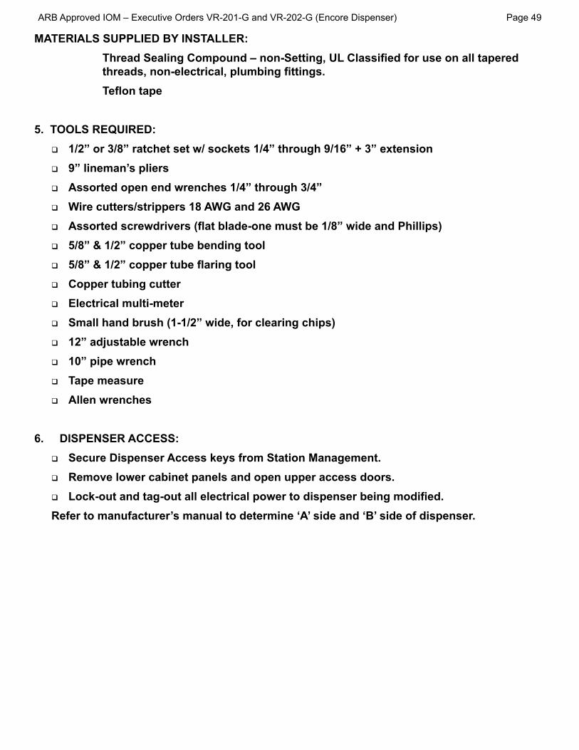
MATERIALS SUPPLIED BY INSTALLER:
5. TOOLS REQUIRED:
9” lineman’s pliersAssorted open end wrenches 1/4” through 3/4”Wire cutters/strippers 18 AWG and 26 AWG
5/8” & 1/2” copper tube bending tool
Copper tubing cutterElectrical multi-meterSmall hand brush (1-1/2” wide, for clearing chips)12” adjustable wrench10” pipe wrenchTape measureAllen wrenches
6. DISPENSER ACCESS:
Remove lower cabinet panels and open upper access doors.
Refer to manufacturer’s manual to determine ‘A’ side and ‘B’ side of dispenser.
Page 50
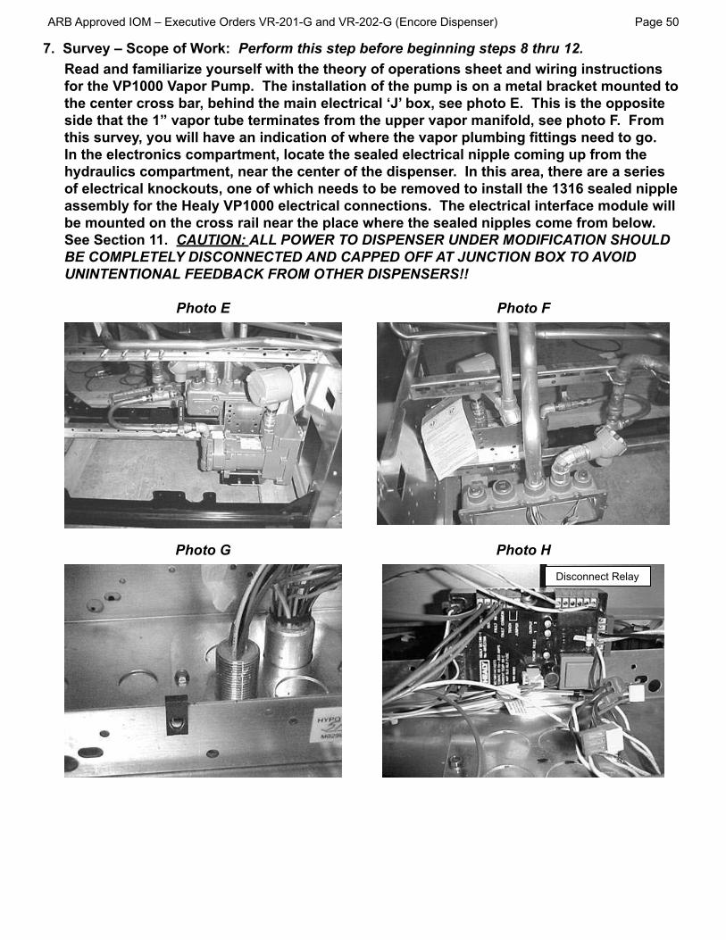
Perform this step before beginning steps 8 thru 12.Read and familiarize yourself with the theory of operations sheet and wiring instructions
the center cross bar, behind the main electrical ‘J’ box, see photo E. This is the opposite side that the 1” vapor tube terminates from the upper vapor manifold, see photo F. From
In the electronics compartment, locate the sealed electrical nipple coming up from the hydraulics compartment, near the center of the dispenser. In this area, there are a series
assembly for the Healy VP1000 electrical connections. The electrical interface module will be mounted on the cross rail near the place where the sealed nipples come from below. See Section 11. CAUTION: ALL POWER TO DISPENSER UNDER MODIFICATION SHOULD BE COMPLETELY DISCONNECTED AND CAPPED OFF AT JUNCTION BOX TO AVOID UNINTENTIONAL FEEDBACK FROM OTHER DISPENSERS!!
Photo E Photo F
Photo G Photo H
Disconnect Relay

Page 51
8. INSTALLING THE HEALY VP1000 SYSTEM:
the 2nd and 3rd holes from the right on the cross rail, select the bolt holes in the
rail. This position assures that the plumbing is self-draining and avoids traps in the vapor line. Do not completely tighten the hardware, see photo J.
Bracket‘U’ bend
Photo J
from the front of the pump.
direction shown in photo J. Slide the pump to allow for matching the location of
washers. (Final tightening is done after the electrical is completely installed.)Using tape, install a 1/2” close nipple into the street elbow. To this, install the 1/2”
the handle on the ball valve points upward when the valve is closed. Install and
To the 1/2 “ tee, install a 1/2 “ x 1/4” reducer bushing into one of the end ‘run’
1/2 “ close nipple into the branch opening.
Page 52
Final connection from the pump to the down pipe is done after the electrical piping has been completed.
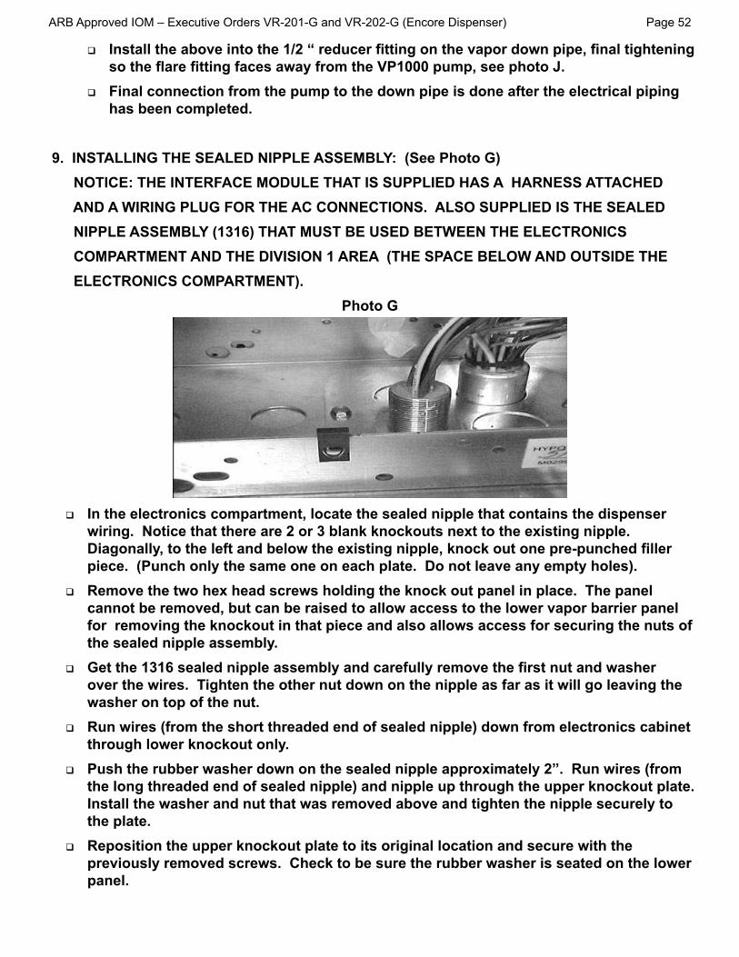
9. INSTALLING THE SEALED NIPPLE ASSEMBLY: (See Photo G) NOTICE: THE INTERFACE MODULE THAT IS SUPPLIED HAS A HARNESS ATTACHED AND A WIRING PLUG FOR THE AC CONNECTIONS. ALSO SUPPLIED IS THE SEALED NIPPLE ASSEMBLY (1316) THAT MUST BE USED BETWEEN THE ELECTRONICS COMPARTMENT AND THE DIVISION 1 AREA (THE SPACE BELOW AND OUTSIDE THE ELECTRONICS COMPARTMENT).
Photo G
In the electronics compartment, locate the sealed nipple that contains the dispenser
piece. (Punch only the same one on each plate. Do not leave any empty holes).
cannot be removed, but can be raised to allow access to the lower vapor barrier panel
the sealed nipple assembly.
over the wires. Tighten the other nut down on the nipple as far as it will go leaving the washer on top of the nut.Run wires (from the short threaded end of sealed nipple) down from electronics cabinet
Push the rubber washer down on the sealed nipple approximately 2”. Run wires (from
Install the washer and nut that was removed above and tighten the nipple securely to the plate.
panel.

To the bottom of the sealed nipple assembly installed above, install a 3/4“ electrical coupling and then, a 3/4“ x 1/2“ reducing bushing into the coupling.Install one of the 1/2” x 7” electrical nipples to the reducing bushing above then the 1/2” coupling and then the other 1/2” x 7” electrical nipple.Get the 1/2” capped elbow and remove the cover. Thread the wires from above through one of the elbow hubs and completely tighten so that the open hub of the elbow faces the electrical wires on top of the motor.Get the 4” long conduit and install in the remaining opening in the capped elbow. (Do not pull wires at this time).Install 3/4” x 1/2” reducing bushings into each opening on the electrical junction box supplied.Install the J-box to the 4” nipple as shown in Photo J. This should position the cover opening to your left and the remaining opening on the J-box approximately over the
attain this alignment.At the VP1000, get and install the threaded half of the 1/2” electrical union over the
Thread a 1/2” electrical close nipple into the remaining half of the electrical union and install into the remaining opening of the J-box.Carefully feed the motor wires into the split union pieces and into the “J” box until the two halves of the union can be slid together and secure.
Carefully feed the wires from the capped elbow into the J-box, pull wires loosely until the cover can be replaced on the capped elbow. Replace cover.In the “J” box, leave about 6” of wire on both the wires coming from the motor and from the sealed nipple, cut off excess wire and strip approximately 1/2” of insulation from all wires.Use wire nuts to join the wires, color for color, together. There may be some extra wires in some sealed nipples, cap these off and dress aside.Replace the cover on the junction box.
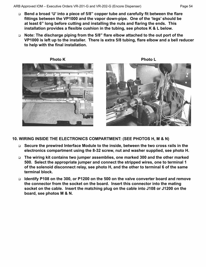
Photo K Photo L
10. WIRING INSIDE THE ELECTRONICS COMPARTMENT: (SEE PHOTOS H, M & N)Secure the prewired Interface Module to the inside, between the two cross rails in the electronics compartment using the 8-32 screw, nut and washer supplied, see photo H.
500. Select the appropriate jumper and connect the stripped wires, one to terminal 1 of the solenoid disconnect relay, see photo H, and the other to terminal 6 of the same
Identify P108 on the 300, or P1200 on the 500 on the valve converter board and remove
board, see photos M & N.

Page 55
Photo M (300) Photo N (500)
P108
P1200
Using the cable harness attached to the module, identify and segregate the “A” side and “B” side connectors. The valve board connections are arranged by product, so it
the board. Connect the ‘signal’ inputs A1, 2, 3 and B1, 2, 3 male/female connectors on
the “A’s” and “B’s” together as there are “A’s” and “B’s” on both sides of the valve converter board. Note only connect the module to active gasoline products – do not connect to diesel or other unused valve connection points.The seven (7) wires from the sealed nipple assembly are connected as follows:
Red (either one) connected to ‘OUTPUT 1’ on output terminal boardRed (other one) connected to ‘OUTPUT 2’ on output terminal boardPurple connected to ‘FAULT’ on output terminal boardOrange connected to ‘FAULT COMMON’ on output terminal boardGreen – connect the ring lug supplied and then attach to chassis, see photo O.
White – connect to Neutral on input terminal strip
is connected to ’Neutral’ on the input terminal strip. The orange connector on the
green wires running together along the center rail and has orange, 3-pin connectorsthat will mate with the power wire from the MC100-1 module, see photo P.

Photo O Photo P
OutputDisconnect
Signals in
11. CONNECTING HEALY SYSTEMS DISPENSING EQUIPMENTCompleting the connection of Healy Systems dispensing equipment requires the installation of Healy Systems Phase II dispenser adaptors, hoses and nozzles (Hanging Hardware).If applicable, remove existing non-Healy hanging hardware (from the dispenser product outlet adaptor, to and including the nozzles).
threads compatible with other Healy Systems equipment. Install necessary adaptor
designation F3 or S3) or balance ready (Healy designation S4).- Healy Vapor Recovery Hoses are available in various lengths to satisfy local
ordinances and still provide “far side” fueling capability. Install these following instructions contained on the shipping box.
- The Healy Systems nozzle Model 900 (EVR) series is the only nozzle necessary to complete the upgrade. Check to be sure the nozzle hook is mounted in the position shown for Healy nozzles in section 16.

Page 57
12. VP1000 Theory of OperationThe Healy Systems VP1000 is a self-contained rotary vane pump, designed for gasoline vapor recovery utilizing various parts of the Healy System Vapor Recovery product line. It is
‘others’ equipment, an electronic interface is required to adapt the targeted pump/dispenser to the new vapor recovery equipment. The interface senses when authorization to dispense has been given and sends signals to the motor to operate at a low speed for one hose, or a higher speed for two hoses. It also functions to shut off the pump/dispenser if it senses that the
liquid gasoline from the vapor path in MPD applications. The Healy nozzle controls the actual
MOTOR SPECIFICATIONS
INTERFACE SPECIFICATIONS

Page 58
13. TESTING THE SYSTEM:
tightened and electrical connections sealed.- Open the product crash valves and restore power to the dispenser.- With the power on, but no nozzles authorized, the VP1000 should not be running
(unless the ambient temperature is below 40°F), but the power LED (yellow) should be energized on the interface module.
- Authorize one handle and the vacuum system should activate when the gasoline
nozzle on each side of dispenser. With each authorization, one of the green LED’s on the interface module should illuminate and the VP1000 activate.
- Note: For unihose dispensers, conduct individual tests for each product grade on each side of the dispener to ensure that the same LED activates for all grades on the same side. If the other LED activates, wiring needs to be corrected.
- Authorize one nozzle, listen to the speed of the VP1000. With one nozzle activated, the speed will be slower than if a nozzle on each side is activated. Activate a nozzle on the other side of the dispenser and listen for the speed to change.
- To test the tightness of the vapor plumbing installed on the suction side of the system requires a 0-100” water column gauge. Connect the gauge into the 1/4” test port of the adaptor tee installed earlier in section 8 Photo J. Continue by following and completing the START-UP / NEW INSTALLATION/ WARRANTY/ ANNUAL TESTING FORM.
14. TROUBLESHOOTING THE VP1000: Use extreme care and caution when performing the tests listed below. If 120 VAC is accidentally applied to the fault or DC terminals, the module will be destroyed.With power applied to the dispenser, but no products authorized, there should be 120 VAC between neutral and 120 VAC on the module terminal strip.As above, with any product authorized, there should be single speed power applied
one GREEN LED should be illuminated. With a second product authorized on the opposite side of the dispenser i.e. one product on each side, the motor should operate at higher speed and there should be 2-3 VDC on both output 1 and 2 (to fault common) and both GREEN LED’s should be illuminated.With the pump running, a fault can be simulated by shorting, with a jumper wire, the “FAULT INPUT” (purple wire) to FAULT COMMON (orange). This should cause the motor to shut off, the solenoid valves to lose power and the dispenser to shut down. Also, as long as the short is maintained, the red LED will be illuminated. Removing the short will not automatically reset the module. To reset the module, remove the short, remove power to the dispenser for twenty seconds and restore power. The module should now be reset and the red led extinguished. This can also be accomplished by using the power reset (PWR RESET) on the module.

Page 59
If diagnosing a problem where the LED is already illuminated, a steady light indicates a low current condition, therefore expect a vane or rotor problem. If the LED is
Annual Testing Form.
the motor. If it detects a problem, on the fourth unsuccessful start, it will short the fault line to signal minus (DC-) and shut down the electronics.
MC100 Interface Module

15. VaporVac™ Removal: Described below are the steps necessary to remove a VaporVac™ and re-plumb the
vapor lines to install the Healy VP1000 series vapor assist recovery system.
Removal of the VaporVac pumps requires the top cover of the dispenser be removed. From the top of the cover, remove the four corner bolts and lifting eyes if present, along with various washers. Remove the cover. Save hardware for reinstallation.With the top removed, notice the ‘loose’ cross rails that the top cover bolts were screwed in to – remove these rails and save for reinstallation after conversion.Be sure all electrical power to the dispenser has been disconnected and disconnect the electrical connections going to each pump.Loosen and disconnect all the vapor pipes from both VAC pumps. Do not remove the vapor pipes from the product outlets, see photos Q and R.
Photo Q Photo R
Into the 3/4” x 1” elbow that was removed above, attach the 3/4” x 1/2” bell reducer supplied in place of the 3/4” coupling shown in Photo S and then install the 1/2” NPT

Photo S Photo T
Electrical wiring and lower cabinet plumbing are the same for Balance or VaporVac™.Deprogram the VaporVac™ system using the “Electronically Disabling the VaporVac System” instruction sheet, enclosed in the Z083V VaporVac™ Kit.After testing, reinstall the cross rails, top cover and hardware removed earlier.

Z083V VaporVac™ KitPhoto U
VAPOR KIT Z083V: for VaporVac™ Kit (See Photo U)
3’ 5/8” OD copper tube, type ‘L’1 1” x 1/2” reducing bushing2 1/2” close nipple1 1/2” x 1/2” x 1/2” tee1 1/2” NPT x 1/4” reducing bushing1 1/2” ball valve1 1/4” pipe plug
1 1/2” street elbow
1 1” x 1/2” bell reducer
1 3/4” x 1/2” bell reducer
2’ 1/2” OD copper tube, type ‘L’
1 “Electronically Disabling the VaporVac System” instruction sheet

16. GILBARCO ENCORE NOZZLE HOOK ADJUSTMENT
Step One: Preparation.
Step Two: Remove nozzle boot(s) from dispensing unit.

D.
and nuts for use later.
under

Upper Hex Head
Vapor A D
VaporVac - OPW, Husky, EmcoWheaton A D
B E
Healy System
Balance - Husky ShortA D
E hook carriage bolt holes as drill guide.
Bottom hole set (“G” on Unmarked. Used
bolt holes as drill guide.
Step Five: Drill New Holes.
drilling guide for the unmarked hole set.
Step Eight: Install nozzle boot(s) onto dispensing unit.
Step Nine: Re-insert Nozzles into the boot.

17. VP1000 Vane & Rotor Service & Replacement Guide
Caution Disconnect power before beginning service.
must2. Disconnect the vapor piping connected to the IN and OUT ports of the VP1000 cover assembly.
remove the cover carefully.
Caution Use a spill cloth when removing the cover, as there may be some gasoline inside the pump cavity.
5. Remove the rotor, vanes and shaft key from the pump housing.
Note:
the pump cavity, pump shaft, rotor, or vanes.
entire vacuum pump needs replacement (p/n VP1000-5).
excessively dirty, the rotor and vanes should be replaced because
alcohol to clean the rotor and vanes.
inside of the pump ring and rear of the pump cavity, the rotor shaft, and the inside of the pump cover.
10. Reposition the shaft (if necessary) so that the shaft key notch is
key onto the shaft.
Note:excessive force. (Rotors and vanes are reversible)
Figure 1VP1000VRCCarbon Rotor(limited availability)
Vane
Vane
Figure 2: VP1000VRC-PEnhancedCarbon Rotor
Note:
Note:
IN and OUT

18. Location Change of Healy VP1000 on Encore Series ISD Enabled Dispensers
vapor line shear valve, the Healy VP1000 Vacuum Pump has been moved up approximately 20
B)position for Encore ISD Enabled Encore Series dispenser option
A) Standard VP1000 position for Healy kit

The ball valve and test port required for Healy startup testing and troubleshooting have been
D) Test Port
C) Ball Valve
Systems manual for the detailed instructions on testing the VP1000 vacuum pump and dispenser
discovered during testing.
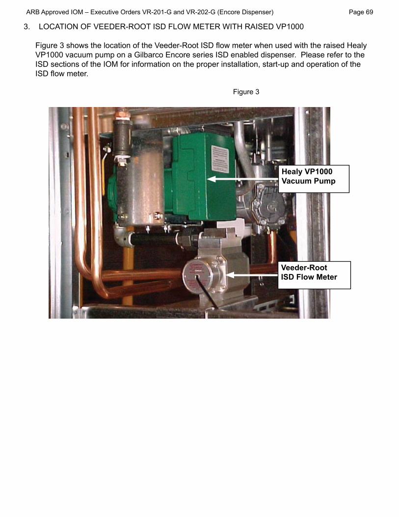
VP1000 vacuum pump on a Gilbarco Encore series ISD enabled dispenser. Please refer to the
Veeder-Root ISD Flow Meter
Healy VP1000 Vacuum Pump

Page 70
a.
b.
Picture 001
Remove outer column sheathing from both c.
sheathing to frame. See Picture 002.
Picture 002
d.
e.removing u-bolt from bottom of tube on the
Picture 005
Page 71
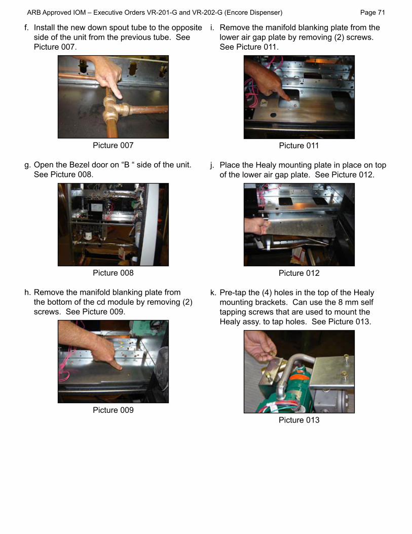
f.side of the unit from the previous tube. See Picture 007.
Picture 007
g.See Picture 008.
Picture 008
Remove the manifold blanking plate from h.the bottom of the cd module by removing (2)
Picture 009
Remove the manifold blanking plate from the i.
See Picture 011.
Picture 011
Place the Healy mounting plate in place on top j.
Picture 012
k.

Page 72
Disconnect any cables coming thru the upper l.conduit plate located in the cd module the
Remove the correct knockout from both m.
head punch. See Picture 17 for correct hole location to knock out.
Picture 015
Remove the Auxiliary junction box from the n.Healy subassembly by removing the nut from the stud on the back of the box. Unhook the
loosening the large nut on the union. See
Picture 017
o.
019, 020.
Picture 018
Picture 019
Picture 020

p.
Picture 021.
Picture 021
Reinstall the auxiliary junction box to the Healy q.sub assembly. Secure the box to the mounting bracket by installing a nut to the stud coming out of the back of the box. See Picture 022.
Picture 022
r.assembly thru the opening in the box and
s.
from the Healy subassembly. Secure plate
Reinstall the upper conduit knockout plate to t.
025.
Picture 025
u.reconnect any cables that you disconnected.

Install a Healy electronic module to the v.
Picture 027
Picture 028
Install cabling to base electronics. See
Picture 029
x.top inlet support and the lip of the side column
Slide the assembly into place and connect y.
the Healy pump assy. Tighten the nut. See

Page 75
for adaptor to connect piping to.
Install the ISD pulser junction box assembly aa.
ab.needed.
ac.
ad.

Date___________________BOTH SIDES OF THIS TEST FORM MUST BE COMPLETED FOR NEW INSTALLATIONS
Systems.
Forms to Healy Systems.
STATE
DISPENSER MAKE VACUUM PUMP SERIAL #
SIDE ADISPENSER EQUIPMENT CHECKLIST - Parts A-1 and A-2 YES NO*
A-1 VR-201 or VR-202?
A-2 Proper installation of the VP1000 requires the test port and ball valve on the inlet side of the vacuum pump. Are the test port and ball valve installed correctly?*If the answer to either A-1 or A-2 is NO, the Healy Warranty is Void.
A-3
CAUTION: REGULATE GASEOUS NITROGEN TO 2.5 PSI (~70” WC) MAXIMUM BEFORE TESTING
cannot5. Slowly
9. Retest until all leaks have been repaired.
A-4 Initial Pressure test reading (“wc) Pressure test reading after 60 seconds (“wc)
PRESSURE TEST2.5 PSI (~70”wc) Maximum

Page 77
Date___________________BOTH SIDES OF THIS TEST FORM MUST BE COMPLETED FOR NEW INSTALLATIONS
Systems.
Forms to Healy Systems.
SIDE BWarranty Service
B-1 and B-2
Start-up/ New Installations/ Annual Testing
B-3 through B-6
B-1 Control Module Fault Light (Circle one) Flashing (LED) Steady (LED)1. All fault conditions require removal and cleaning or replacement of the rotor and vanes located inside the vacuum pumps round front cover assembly. Use the VP1000 ROTOR & VANE SERVICE AND REPLACE-MENT GUIDE
B-2 the module for 20 seconds to reset the system
B-3
seconds.5. Open the ball valve at the pump inlet.
7. Retest until all leaks have been repaired.
Note: If the initial vacuum reading is less than 60” wc, it could indicate a problem with the VP1000.Remove the dispenser from service. Use the troubleshooting section of the manual to investigate
Inte
grity
Tes
t
B-4 VP1000 as vacuum source
B-5dispensing. Repeat test for the other side of the dispenser.
Note: If the dispensing vacuum is less than 60” wc, remove the dispenser from service. See the trouble-Dis
pens
erVa
acuu
m T
est
B-6
use the troubleshooting section of the manual to investigate problem or contact the Aud
ible
Incr
ease
Test