Embed Size (px)
Citation preview


GFA INTERNATIONAL FLORIDA’S LEADING ENGINEERING SOURCE
Report of Geotechnical Exploration Marsh Avenue WM Replacement
Marsh Avenue (Between Ballard Road and Michigan Ave.) Fort Myers, Lee County, Florida
June 2, 2015 GFA Project No.15-0410
For: Lee County Utilities
Addendum No. 1- 02/02/2016

Since 1988 Florida’s Leading Engineering Source
Environmental • Geotechnical • Construction Materials Testing • Threshold and Special Inspections • Plan Review & Code Compliance
June 2, 2015 Ms. Jessica Muñoz, P.E. Project Manager Lee County Utilities 1500 Monroe Street Ft. Myers, Florida 33901 Phone: (239) 533-8155 Email: [email protected] Site: Marsh Avenue Water Main Replacement Marsh Avenue (Between Ballard Rd. and Michigan Ave.) Fort Myers, Lee County, Florida GFA Project No.15-0410 Dear Ms. Munoz: GFA International, Inc. (GFA) has completed the subsurface exploration and geotechnical engineering evaluation for the above-referenced project in accordance with the geotechnical and engineering service agreement for this project. The scope of services was completed in accordance with our Geotechnical Engineering Proposal (15-0410.00), planned in conjunction with and authorized by you. EXECUTIVE SUMMARY The purpose of our subsurface exploration was to classify the nature of the subsurface soils and general geomorphic conditions and evaluate their impact upon the proposed construction. This report contains the results of our subsurface exploration at the site and our engineering interpretations of these, with respect to the project characteristics described to us including providing recommendations for site preparation and the design of the foundation system. Based on information provided by the Client, GFA understands that this portion of the project consists of the water main replacement for the section that runs along Marsh Avenue from Ballard Road to Michigan Avenue. GFA was provided with an aerial site plan with 5 boring locations selected by the Client. Based on the proposed construction, the Client requested the borings be completed to depths of 6 to 15 feet below existing grade and located within the right-of–way area on the west shoulder of Marsh Avenue to identify the underlying soil conditions. If the project scope has been revised, please inform GFA International so that we may review our recommendations with respect to any modifications. The following testing was completed for this study; Four (4) Hand Auger (HA) borings (B-1 through B-4) to depths of approximately 6 feet
below ground surface (BGS) and one (1) Standard Penetration Test (SPT) boring (B-5) to a depth of approximately 15 feet below ground surface (BGS).
5851 Country Lakes Drive • Fort Myers, Florida 33905 • (239) 489-2443 • (239) 489-3438 (fax) • www.teamgfa.com
OFFICES THROUGHOUT FLORIDA


Marsh Avenue Water Main Replacement Geotechnical Report Marsh Avenue, Fort Myers, Lee County, Florida June 2, 2015 GFA Project No. 15-0410 Page 3 of 8
TABLE OF CONTENTS 1.0 INTRODUCTION ................................................................................................................. 4 1.1 Scope of Services ........................................................................................................... 4 1.2 Project Description .......................................................................................................... 4 2.0 OBSERVATIONS ................................................................................................................ 4 2.1 Site Inspection................................................................................................................. 4 2.2 Field Exploration ............................................................................................................. 4 2.3 Laboratory Analysis ......................................................................................................... 5 2.4 Geomorphic Conditions ................................................................................................... 5 2.5 Hydrogeological Conditions ............................................................................................. 5 3.0 ENGINEERING EVALUATION AND RECOMMENDATIONS.............................................. 6 3.1 General ........................................................................................................................... 6 3.2 Pipe Bedding and Initial Backfill ...................................................................................... 6 3.3 Trench Excavation .......................................................................................................... 6 3.4 Trench Backfill ................................................................................................................. 7 3.5 Dewatering of Excavations .............................................................................................. 7 3.6 Site Preparation Procedures ........................................................................................... 8 4.0 REPORT LIMITATIONS ...................................................................................................... 8 5.0 BASIS FOR RECOMMENDATIONS ................................................................................... 8 Appendix A - Vicinity Map Appendix B - Test Location Plan Appendix C - Notes Related to Borings Appendix D - Record of Test Borings Appendix E - Discussion of Soil Groups
Marsh Avenue Water Main Replacement Geotechnical Report Marsh Avenue, Fort Myers, Lee County, Florida June 2, 2015 GFA Project No. 15-0410 Page 4 of 8
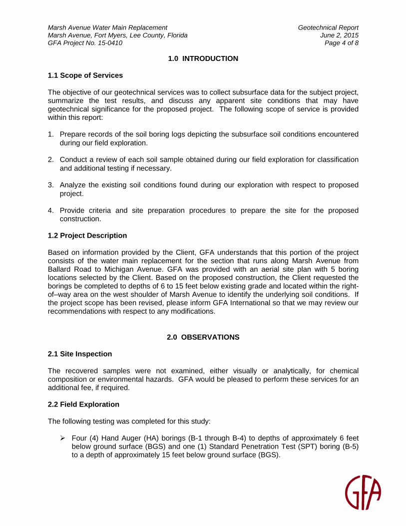
1.0 INTRODUCTION 1.1 Scope of Services The objective of our geotechnical services was to collect subsurface data for the subject project, summarize the test results, and discuss any apparent site conditions that may have geotechnical significance for the proposed project. The following scope of service is provided within this report:
1. Prepare records of the soil boring logs depicting the subsurface soil conditions encountered during our field exploration.
2. Conduct a review of each soil sample obtained during our field exploration for classification and additional testing if necessary.
3. Analyze the existing soil conditions found during our exploration with respect to proposed project.
4. Provide criteria and site preparation procedures to prepare the site for the proposed
construction. 1.2 Project Description Based on information provided by the Client, GFA understands that this portion of the project consists of the water main replacement for the section that runs along Marsh Avenue from Ballard Road to Michigan Avenue. GFA was provided with an aerial site plan with 5 boring locations selected by the Client. Based on the proposed construction, the Client requested the borings be completed to depths of 6 to 15 feet below existing grade and located within the right-of–way area on the west shoulder of Marsh Avenue to identify the underlying soil conditions. If the project scope has been revised, please inform GFA International so that we may review our recommendations with respect to any modifications.
2.0 OBSERVATIONS 2.1 Site Inspection The recovered samples were not examined, either visually or analytically, for chemical composition or environmental hazards. GFA would be pleased to perform these services for an additional fee, if required. 2.2 Field Exploration The following testing was completed for this study: Four (4) Hand Auger (HA) borings (B-1 through B-4) to depths of approximately 6 feet
below ground surface (BGS) and one (1) Standard Penetration Test (SPT) boring (B-5) to a depth of approximately 15 feet below ground surface (BGS).

Marsh Avenue Water Main Replacement Geotechnical Report Marsh Avenue, Fort Myers, Lee County, Florida June 2, 2015 GFA Project No. 15-0410 Page 5 of 8 The locations of the borings performed are illustrated in “Appendix B: Test Location Plan". The Standard Penetration Test (SPT) boring method was used as the investigative tool within the borings. SPT tests were performed in substantial accordance with ASTM Procedure D-1586, “Penetration Test and Split-Barrel Sampling of Soils”. This test procedure consists of driving a 1.4-inch I.D. split-tube sampler into the soil profile using a 140-pound hammer falling 30 inches. The number of blows per foot, for the second and third 6-inch increment, is an indication of soil strength. The soil samples recovered from the soil borings were visually classified and their stratification is illustrated in “Appendix D: Record of Test Borings". It should be noted that soil conditions might vary between the strata interfaces, which are shown. The soil boring data reflect information from a specific test location only. Site specific test locations were staked in the field by your representatives. The indicated depth and location of each test was approximated based upon existing grade and estimated distances and relationships to obvious landmarks. The boring depths were selected based on our knowledge of vicinity soils and to include the zone of soil likely to be stressed by the proposed construction. 2.3 Laboratory Analysis Soil samples recovered from our field exploration were returned to our laboratory where they were visually examined in general accordance with ASTM D-2488. Samples were evaluated to obtain an accurate understanding of the soil properties and site geomorphic conditions. After a thorough visual examination of the recovered site soils, no laboratory testing was deemed necessary. Bag samples of the soil encountered during our field exploration will be held in our laboratory for your inspection for 30 days and then discarded unless we are notified otherwise in writing. 2.4 Geomorphic Conditions Boring logs derived from our field exploration are presented in “Appendix D: Record of Test Borings”. The boring logs depict the observed soils in graphic detail. The Standard Penetration Test borings indicate the penetration resistance, or N-values, logged during the drilling and sampling activities. The classifications and descriptions shown on the logs are generally based upon visual characterizations of the recovered soil samples. All soil samples reviewed have been depicted and classified in general accordance with the Unified Soil Classification System, modified as necessary to describe typical southwest Florida conditions. See “Appendix E: Discussion of Soil Groups", for a detailed description of various soil groups. The subsurface soil conditions encountered at this site generally consists of very loose to dense sand (SP) to silty sand (SM) to the boring termination depths. Please refer to “Appendix D - Record of Test Borings” for a detailed account of each boring. 2.5 Hydrogeological Conditions On the dates of our field exploration, the groundwater table was encountered at depths approximately 5.5 to 5.8 feet below the existing ground surface. The groundwater table will fluctuate seasonally depending upon local rainfall and other site specific and/or local influences such as tidal events. Brief ponding of stormwater may occur across the site after heavy rains.

Marsh Avenue Water Main Replacement Geotechnical Report Marsh Avenue, Fort Myers, Lee County, Florida June 2, 2015 GFA Project No. 15-0410 Page 6 of 8 No additional investigation was included in our scope of work in relation to the wet seasonal high groundwater table or any existing well fields in the vicinity. Well fields may influence water table levels and cause significant fluctuations. If a more comprehensive water table analysis is necessary, please contact our office for additional guidance.
3.0 ENGINEERING EVALUATION AND RECOMMENDATIONS 3.1 General The geotechnical evaluations for the proposed construction site are based on the subsurface soil and groundwater conditions encountered during this study, the project information made available, our site observations, and our experience in the vicinity. The test data has been evaluated using established geotechnical parameters of the soils recorded at this site, laboratory test results, and the observed performance of similar soil types. Based on the soil conditions encountered in the performed borings, the near surface soils can be classified as “Common Fill” based upon the definitions contained in the Lee County Technical Specifications, Section 2223, Backfilling. Design of Pipe Bedding, Initial Backfill and Trench Backfill shall be in accordance with the aforementioned Lee County Technical Specifications. 3.2 Pipe Bedding and Initial Backfill Based on the in-situ soils being classified as “Common Fill”, pipe bedding and initial fill meeting the requirements of “Select Fill” shall be used. Material selection, site preparation and compaction shall be specified in accordance with the applicable sections of the Lee County Technical Specifications, Section 2223, Backfilling. 3.3 Trench Excavation In Federal Register, Volume 54, No. 209 (October 1989), the United States Department of Labor, Occupational Safety and Health Administration (OSHA) amended its “Construction Standards for Excavations, 29 CFR, part 1926, Subpart P”. This document was issued to better insure the safety of workmen entering trenches or excavations. It is mandated by this federal regulation that all excavations, whether they be utility trenches, basement excavations or footing excavations, be constructed in accordance with the OSHA guidelines. The contractor is solely responsible for designing and constructing stable, temporary excavations and should shore, slope, or bench the sides of any excavations deeper than 4 feet as required to maintain stability of both the excavation sides and bottom. The contractor’s responsible person, as defined in 29 CFR Part 1926, should evaluate the soil exposed in the excavations as part of the contractor’s safety procedures. In no case should slope height, slope inclination, or excavation depth, including utility trench excavation depth, exceed those specified in local, state, and federal safety regulations. GFA is providing this information solely as a service to our client. GFA is not assuming responsibility for construction site safety or the contractor’s activities; such responsibility is not being implied and should not be inferred.

Marsh Avenue Water Main Replacement Geotechnical Report Marsh Avenue, Fort Myers, Lee County, Florida June 2, 2015 GFA Project No. 15-0410 Page 7 of 8 Control of the groundwater (e.g. well points) may be necessary during the installation underground utilities. Control is not anticipated for pavement reconstruction (if applicable). The following cautions should be exercised: • Excavations shall be performed to the limits required for installation. Furthermore, the site
preparation contractor should carefully monitor the sides of the excavation, and should adequately slope them so that they do not fail during the excavation or subsequent backfilling operations. CAUTION: Due to the very loose nature of the subsurface soils, trench stabilization as noted above will likely be necessary to prevent slope failures.
• The soil parameters listed below are estimated made from the SPT tests for use in the
design of any temporary shoring for excavation:
Angle of Internal Friction 28 degrees Unconfined Compressive Strength (Su) N/A
Unit Weights for Lateral Pressure Determination*
Above Water Table 110 pounds per cubic foot Below Water Table 50 pounds per cubic foot
* Lateral earth pressures are ultimate values and are assumed to act on buried
vertical faces of the tower anchors (Ka and Kp to be based on angle of internal friction).
3.4 Trench Backfill Based on the in-situ soils being classified as “Common Fill”, trench backfill material selection, site preparation and compaction shall be specified in accordance with the applicable sections of the Lee County Technical Specifications, Section 2223, Backfilling. When trenches are cut in pavements or areas to be paved, compaction shall be equal to 98% of maximum density. In unpaved portions of the Right-of-Way areas, compaction shall be not less than 95% of maximum density. 3.5 Dewatering of Excavations The high groundwater tables, if encountered during construction, in the vicinity of excavations shall be reduced to prevent water inflow into excavations. Each excavation shall be kept dry during subgrade preparation and continually thereafter until installation of the pipe. Based on the groundwater levels encountered, control of the groundwater (e.g. well points) may be necessary during the installation of underground utilities. Control is not anticipated for pavement reconstruction (if applicable).

Marsh Avenue Water Main Replacement Geotechnical Report Marsh Avenue, Fort Myers, Lee County, Florida June 2, 2015 GFA Project No. 15-0410 Page 8 of 8
4.0 REPORT LIMITATIONS This consulting report has been prepared for the exclusive use of the current project owners and other members of the design team for the Marsh Avenue Water Main Replacement project located in Fort Myers, Lee County, Florida. This report has been prepared in accordance with generally accepted local geotechnical engineering practices; no other warranty is expressed or implied. The evaluation submitted in this report, is based in part upon the data collected during a field exploration, however, the nature and extent of variations throughout the subsurface profile may not become evident until the time of construction. If variations then appear evident, it may be necessary to reevaluate information and professional opinions as provided in this report. In the event changes are made in the nature, design, or locations of the proposed structure, the evaluation and opinions contained in this report shall not be considered valid, unless the changes are reviewed and conclusions modified or verified in writing by GFA International. GFA is not responsible for damage caused by soil improvement and/or construction activity vibrations related to this project. GFA is also not responsible for damage concerning drainage or moisture related issues for the proposed or nearby structures.
5.0 BASIS FOR RECOMMENDATIONS
The analysis and recommendations submitted in this report are based on the data obtained from the tests performed at the locations indicated on the attached figure in Appendix B. This report does not reflect any variations, which may occur between borings. While the borings are representative of the subsurface conditions at their respective locations and for their vertical reaches, local variations characteristic of the subsurface soils of the region are anticipated and may be encountered. The delineation between soil types shown on the soil logs is approximate and the description represents our interpretation of the subsurface conditions at the designated boring locations on the particular date drilled. Any third party reliance of our geotechnical report or parts thereof is strictly prohibited without the expressed written consent of GFA International. The methodology (ASTM D-1586) used in performing our borings and for determining penetration resistance is specific to the sampling tools utilized and does not reflect the ease or difficulty to advance other tools or materials.

Appendix A - Vicinity Map

MiamiMiamiMiamiMiamiMiamiMiamiMiamiMiamiMiami
TallahasseeTallahasseeTallahasseeTallahasseeTallahasseeTallahasseeTallahasseeTallahasseeTallahassee
TampaTampaTampaTampaTampaTampaTampaTampaTampa
JacksonvilleJacksonvilleJacksonvilleJacksonvilleJacksonvilleJacksonvilleJacksonvilleJacksonvilleJacksonville
FLORIDA
NN
SITE LOCATIONFort Myers, FL
VICINITY MAP
Marsh Avenue WMReplacement
Marsh Ave (Between Ballard Rd and Michigan Ave)
Fort Myers, Florida
GFA International Project No.: 15-0410
SITE LOCATION

Appendix B - Test Location Plan

MiamiMiamiMiamiMiamiMiamiMiamiMiamiMiamiMiami
TallahasseeTallahasseeTallahasseeTallahasseeTallahasseeTallahasseeTallahasseeTallahasseeTallahassee
TampaTampaTampaTampaTampaTampaTampaTampaTampa
JacksonvilleJacksonvilleJacksonvilleJacksonvilleJacksonvilleJacksonvilleJacksonvilleJacksonvilleJacksonville
FLORIDA
TEST LOCATION PLAN
*Scale is an approximation and may not be accurate.
TEST BORING LOCATION
B-1B-1
B-2B-2
B-3B-3
NN
Marsh Avenue WMReplacement
Marsh Ave (Between Ballard Rd and Michigan Ave)
Fort Myers, Florida
GFA International Project No.: 15-0410
SITE LOCATIONFort Myers, FL
B-4B-4
B-5B-5

Appendix C - Notes Related to Borings
NOTES RELATED TO RECORDS OF TEST BORING AND
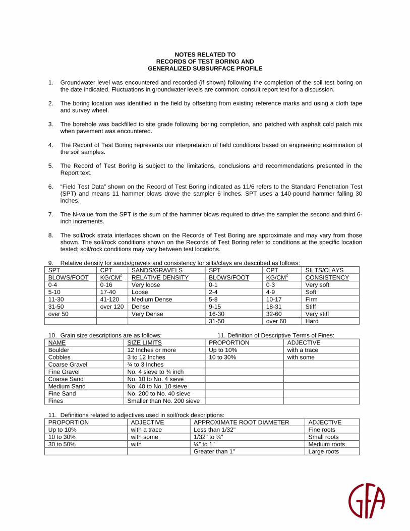
GENERALIZED SUBSURFACE PROFILE 1. Groundwater level was encountered and recorded (if shown) following the completion of the soil test boring on
the date indicated. Fluctuations in groundwater levels are common; consult report text for a discussion. 2. The boring location was identified in the field by offsetting from existing reference marks and using a cloth tape
and survey wheel. 3. The borehole was backfilled to site grade following boring completion, and patched with asphalt cold patch mix
when pavement was encountered. 4. The Record of Test Boring represents our interpretation of field conditions based on engineering examination of
the soil samples. 5. The Record of Test Boring is subject to the limitations, conclusions and recommendations presented in the
Report text. 6. “Field Test Data” shown on the Record of Test Boring indicated as 11/6 refers to the Standard Penetration Test
(SPT) and means 11 hammer blows drove the sampler 6 inches. SPT uses a 140-pound hammer falling 30 inches.
7. The N-value from the SPT is the sum of the hammer blows required to drive the sampler the second and third 6-
inch increments. 8. The soil/rock strata interfaces shown on the Records of Test Boring are approximate and may vary from those
shown. The soil/rock conditions shown on the Records of Test Boring refer to conditions at the specific location tested; soil/rock conditions may vary between test locations.
9. Relative density for sands/gravels and consistency for silts/clays are described as follows: SPT CPT SANDS/GRAVELS SPT CPT SILTS/CLAYS BLOWS/FOOT KG/CM2 RELATIVE DENSITY BLOWS/FOOT KG/CM2 CONSISTENCY 0-4 0-16 Very loose 0-1 0-3 Very soft 5-10 17-40 Loose 2-4 4-9 Soft 11-30 41-120 Medium Dense 5-8 10-17 Firm 31-50 over 120 Dense 9-15 18-31 Stiff over 50 Very Dense 16-30 32-60 Very stiff 31-50 over 60 Hard 10. Grain size descriptions are as follows: 11. Definition of Descriptive Terms of Fines: NAME SIZE LIMITS PROPORTION ADJECTIVE Boulder 12 Inches or more Up to 10% with a trace Cobbles 3 to 12 Inches 10 to 30% with some Coarse Gravel ¾ to 3 Inches Fine Gravel No. 4 sieve to ¾ inch Coarse Sand No. 10 to No. 4 sieve Medium Sand No. 40 to No. 10 sieve Fine Sand No. 200 to No. 40 sieve Fines Smaller than No. 200 sieve 11. Definitions related to adjectives used in soil/rock descriptions: PROPORTION ADJECTIVE APPROXIMATE ROOT DIAMETER ADJECTIVE Up to 10% with a trace Less than 1/32" Fine roots 10 to 30% with some 1/32" to ¼” Small roots 30 to 50% with ¼” to 1" Medium roots Greater than 1" Large roots

Appendix D - Record of Test Borings

SOIL PROFILES SOIL PROFILE LEGEND SOIL LEGEND
B-X = BORING NUMBER
SOIL TYPE XN = SPT TESTVALUE
GROUND WATER
INDICATES PRACTICALREFUSAL TO BORINGEQUIPMENT
= INDICATES GRADUAL TRANSITION
IN SOIL TYPES
NOTES:
LEVEL
SO
ILS
YM
BO
L
SOIL CLASSIFICATION
CORRELATION OF N - VALUES WITH RELATIVE
DENSITY AND CONSISTENCY
CORRELATION OF N - VALUES WITH HARDNESS DESCRIPTION
COHESIONLESS SOIL SILTS AND CLAYS LIMEROCK
N - VALUE N - VALUE N - VALUERELATIVE DENSITY CONSISTENCY RELATIVE DENSITY
0 - 2 UNDER 1 0 - 19VERY LOOSE VERY SOFT VERY SOFT3 - 8 1 - 3 20 - 49LOOSE SOFT SOFT
9 - 24 4 - 6 50 - 100MEDIUM DENSE FIRM MEDIUM HARD
25 - 40 7 - 12 50 FOR 3 TO 5"DENSE STIFF MODERATELY HARD
OVER 40 13 - 24 50 FOR 0 TO 2"VERY DENSE VERY STIFF HARD
OVER 24 HARD
APPROXIMATE
FINESCONTENT
MODIFIERS
5% TO 15%
16% TO 25%
26% TO 49%
SLIGHTLY SILTY OR SLIGHTLY CLAYEY
SILTY OR CLAYEY
VERY SILTY OR VERY CLAYEY
APPROXIMATE SAND/
GRAVELCONTENT
MODIFIERS
5% TO 15%
16% TO 25%
26% TO 49%
SLIGHTLY SANDY OR SLIGHTLY GRAVELLY
SANDY OR GRAVELLY
VERY SANDY OR VERY GRAVELLY
APPROXIMATE
ROOT CONTENT MODIFIERS
5% TO 10%
11% TO 20%
21% TO 40%
TRACE
TRACE TO SOME
SOME
41% TO 60% AND
N - STANDARD PENETRATION RESISTANCE TEST(SPT) VALUE. NUMBERS TO THE LEFT OFBORINGS INDICATE SPT VALUE FOR 12-INCHESOF PENETRATION (UNLESS OTHERWISE NOTED).
WOH - BORING INTERVAL ADVANCED UNDERWEIGHT OF HAMMER.
LFC - LOSS OF DRILLING FLUID CIRCULATION.
RECORD OF TEST BORINGS
Client: Lee County Utilities
Project: Marsh Avenue WMReplacementFort Myers, Lee County, Florida
Approved by: DM
Date: 05/29/15
Job No: 15-0410
Drawn By: WPG
GFA International, Inc.5851 Country Lakes DriveFort Myers, Florida 33905
239-489-2443 * TeamGFA.com
1
Light gray to gray, brown to dark brown, SAND,loose to medium dense (SP)
0
15
DE
PT
HIN
FE
ET
2
B-1N-VAL
B-2N-VAL
Gray SILTY SAND, very loose (SM)
B-3N-VAL
3
SOME SHELLAND GRAVEL
B-4N-VAL
B-5N-VAL
1
2
3
4
5
6
7
8
9
10
11
12
13
14
05/28/15
1 1 1 1
1
2
05/28/15 05/28/15 05/28/15
05/28/15
6
1
HANDAUGER

Appendix E - Discussion of Soil Groups

DISCUSSION OF SOIL GROUPS
COARSE GRAINED SOILS GW and SW GROUPS. These groups comprise well-graded gravelly and sandy soils having little or no plastic fines (less than 5 percent passing the No. 200 sieve). The presence of the fines must not noticeably change the strength characteristics of the coarse-grained fraction and must not interface with it's free-draining characteristics. GP and SP GROUPS. Poorly graded gravels and sands containing little of no plastic fines (less than 5 percent passing the No. 200 sieve) are classed in GP and SP groups. The materials may be called uniform gravels, uniform sands or non-uniform mixtures of very coarse material and very fine sands, with intermediate sizes lacking (sometimes called skip-graded, gap-graded or step-graded). This last group often results from borrow pit excavation in which gravel and sand layers are mixed. GM and SM GROUPS. In general, the GM and SM groups comprise gravels or sands with fines (more than 12 percent passing the No. 200 sieve) having low or no plasticity. The plasticity index and liquid limit of soils in the group should plot below the "A" line on the plasticity chart. The gradation of the material is not considered significant and both well and poorly graded materials are included. GC and SC GROUPS. In general, the GC and SC groups comprise gravelly or sandy soils with fines (more than 12 percent passing the No. 200 sieve), which have a fairly high plasticity. The liquid limit and plasticity index should plot above the "A” line on the plasticity chart.
FINE GRAINED SOILS ML and MH GROUPS. In these groups, the symbol M has been used to designate predominantly silty material. The symbols L and H represent low and high liquid limits, respectively, and an arbitrary dividing line between the two is set at a liquid limit of 50. The soils in the ML and MH groups are sandy silts, clayey silts or inorganic silts with relatively low plasticity. Also included are loess type soils and rock flours. CL and CH GROUPS. In these groups the symbol C stands for clay, with L and H denoting low or high liquid limits, with the dividing line again set at a liquid limit of 50. The soils are primarily inorganic clays. Low plasticity clays are classified as CL and are usually lean clays, sandy clays or silty clays. The medium and high plasticity clays are classified as CH. These include the fat clays, gumbo clays and some volcanic clays.

OL and OH GROUPS. The soil in the OL and OH groups are characterized by the presence of organic odor or color, hence the symbol O. Organic silts and clays are classified in these groups. The materials have a plasticity range that corresponds with the ML and MH groups.
HIGHLY ORGANIC SOILS
The highly organic soils are usually very soft and compressible and have undesirable construction characteristics. Particles of leaves, grasses, branches, or other fibrous vegetable matter are common components of these soils. They are not subdivided and are classified into one group with the symbol PT. Peat humus and swamp soils with a highly organic texture are typical soils of the group.

Summary of Verified Utilities‐Marsh Ave. From Michigan Ave. to Ballard Rd. (Lee County) AIM Engineering & Surveying Inc.
Abbreviations Field work was performed between: 04/09/15‐04/17/15AC: Asbestos Concrete Coordinates shown are in U.S. Survey Feet, NAD 83 Florida State Plane East ZoneCIP: Cast Iron Pipe Elevations shown are based on North American Vertical Datum 88 (NAVD88)COFM: City of Ft. MyersVvh: Verified Vertical Elevation and Horizontal Location
Vvh No.Utility Description(Owner, Type) Size Material Northing Easting
Existing Surface Elevation Top Elevation Comments
1 Water Main‐Believed to be COFM 18"x8" CIP 841455.57 712283.04 18.2 15.15 Tee2 Water Main‐Believed to be COFM 18" CIP 841471.91 712275.19 18.1 14.723 Unknown 6" Steel 841483.90 712276.14 18.5 14.284 Water Main‐Believed to be COFM 18" CIP 841468.31 712279.58 18.2 14.815 Water Main‐Believed to be Lee Co. 12" CIP 841529.36 712278.81 17.9 15.366 Water Main‐Believed to be COFM 6" AC 841547.58 712321.47 18.4 15.877 Water Main‐Believed to be COFM 6" AC 841863.26 712311.68 18.1 15.358 Water Main‐Believed to be COFM 6" AC 842192.91 712303.00 17.9 15.319 Water Main‐Believed to be COFM 6" AC 842530.29 712293.16 17.7 14.9410 Water Main‐Believed to be Lee Co. 12" CIP 842873.47 712253.48 17.0 14.4611 Water Main‐Believed to be COFM 6" AC 842788.99 712287.96 17.5 14.6812 Water Main‐Believed to be Lee Co. 12" CIP 841805.39 712290.68 18.7 15.1613 Water Main‐Believed to be Lee Co. 12" CIP 842132.34 712282.17 18.3 15.4914 Water Main‐Believed to be Lee Co. 12" CIP 842530.61 712276.61 18.3 15.04
Addendum No 1 - 2/2/2016