Embed Size (px)
Citation preview
GEZE SWING DOOR SYSTEMSCLEVER SYSTEMS. FOR BARRIER-FREE ACCESS.
G E Z E AU TO M AT I C D O O R S YS T E M S
BE WEGUNG MIT SYSTEM
Cover photo and photo on page 2: GEZE GmbH

3
Automatic swing door systems
ECturn, EMD, TSA 160 NT AND POWERTURN
Swing Door Systems
Foreword: GEZE swing door systems 4
Overview table 5
Types of installation 6
Automatic swing door systems
For fi re and smoke protection doors (F) 7
With integrated closing sequence control (IS) 7
With integrated closing sequence control for double-leaf fi re and smoke protection doors (F-IS) 8
With integrated closing sequence control for double-leaf doors, automatic doors and door closer function (IS/TS) 8
For fresh air supply as well as doors in emergency exits (Invers) 9
For large and heavy doors, as well as frequently used doors (EN7) 9
Special area of application: Accessible toilet 10
Swing door drives
GEZE ECturn 11
GEZE ECturn Inside 23
GEZE Slimdrive EMD 28
GEZE TSA 160 NT 42
GEZE Powerturn 54
Accessories (Cover, mounting plate, link arm, roller guide rail with lever) 69
Operation 70
Activation 71
Protection 73
Service Tools 79
References 80
TABLE OF CONTENTS

GEZE swing door systems
Open and close doors easily
The automatic swing door systems from GEZE make passing through a door easier every time when manual opening is too hard or inconve-nient. They are recommended in public as well as in private buildings, when convenience, accessibility, safety and hygiene are necessary or when energy has to be saved: in shopping centres, schools, office or industrial buildings, airports, hospitals, vestibules or in individual homes.
ECturnThe electromechanical swing door drive ECturn is recommended for single-leaf smaller internal and entrance doors of up to 125 kilogram with moderate access frequency. The ECturn is so small and discreet that even frameless all-glass doors can be automated. In addition, the ECturn Inside enables an “invisible” door automation. Thanks to its small dimensions, it can be integrated in the door leaf or in the frame. The ECturn Inside was labelled with the Interior Innovation Award by the German Design Council.
Slimdrive EMDThe electromechanical swing door drive Slimdrive EMD is suitable for single and double-leaf doors of up to 230 kilogram, slim profiles and small spaces. The Slimdrive EMD, with a drive height of only seven centimetres, various cover designs and adjustment options, fits in every door situation and is also approved in fire protection doors. It was already labelled with two Plus X Awards.
TSA 160 NTThe approved electrohydraulic swing door drive TSA 160 NT opens and closes doors of up to 310 kilogram safely and reliably. It manages high public access easily. Multiple variations enable various applications.
PowerturnThe electromechanical swing door drive Powerturn provides a high function and design variety. The robust, efficient drive opens single and double-leaf large and heavy doors with leaf weights of up to 600 kilogram quietly and reliably. With its 7-cm-optics, it fits in every door design. Thanks to the Smart swing function, even manual door-opening is child‘s play. Hence the Powerturn is a prime example for Universal Design.
Design possibilities for swing door systemsDIN 18650 The industrial standard DIN 18650 was created to be able to gu-arantee operators and users of automatic doors optimum safety. GEZE swing door systems with automatic function have been type-tested to DIN 18650 and certified.
EN 16005The new European standard EN 16005 sets out the design requirements and testing methods used to ensure the safe use of automatic doors. The new standard has created a Europe-wide safety standard for automatic doors. All automatic door systems and safety sensors from GEZE meet the EN 16005 standard and are available.
DIN 18040DIN 18040 formulates the safety objectives for publicly accessible buildings and apartments and shows the requirements of people with sensory and cognitive limitations. The automatic swing door systems of GEZE are attractive not only for people with limited mobility. Accessibility is also reflected in the concept of Universal Design and in the topical subject “Inclusion”. According to this concept, buildings must be made easy to access for the largest possible group of people, and it must be possible to use them without help.
1
2
34
56
7
8
9
10
1 = Drive2 = Radar movement detector3 = Plastic elbow switch4 = Programme switch 5 = Proximity switch6 = Elbow switch7 = Glass LED sensor button8 = Interruption button9 = Foot contact switch10 = Sensor strip
4
Automatic swing door systems
ECturn, EMD, TSA 160 NT AND POWERTURN
GEZE AUTOMATIC DOOR SYSTEMS

5
Automatic swing door systems
ECturn, EMD, TSA 160 NT AND POWERTURN
Swing Door Systems
ECturn Slimdrive EMD TSA 160 NT Powerturn
Product features
Dimensions drive (height x width x depth) 60x580x60 mm 70x650x121 mm 100x690x121 mm 70×720×130 mm
Leaf weight (max.) 125 kg180 kg
230 kg*250 kg
310 kg**600 kg
Leaf width (min.)GLS / RS1
650 mm850 mm
690 mm 800 mmGST 750 mm
Leaf width (max.)GLS / RS1
1100 mm 1400 mm1400 mm
1600 mm**1600 mm
GST
Hinge clearance on double-leaf doorsGLS / RS1 – 1700-2500 mm 1470-3200
mm**1600 – 3200 mm
GST – 1500-2800 mm
Opening and closing speed adjustable ● ● ● ●
Electrical closing sequence control ● ● ●
Electromechanical drive ● ● ●
Electrohydraulic drive ●
External doors / Internal doors – / ● ● / ● ● / ● ● / ●
Integrated in door leaf or in door frame ●***
1-leaf / 2-leaf ● / – ● / ● ● / ● ● / ●
Guide rail / Roller guide rail / Link arm ● / - / ● - / ● / ● - / ● / ● - / ● / ●
Functions
Automatic ● ● ● ●
Push & Go adjustable ● ● ● ●
Low-Energy ● ● ●
Smart swing ●
Servo ●
Variants
For fire and smoke protection doors (F) ●* / **** ● ●
With integrated smoke switch (F/R) ●* / **** ●
With integrated closing sequence control (IS) ●* ● ●
With integrated closing sequence control for double-leaf fire and smoke protection doors (F-IS)
●* / **** ● ●
With integrated closing sequence control for double-leaf doors, automatic doors and door closer function (IS/TS)
● ●
For fresh air supply as well as doors in emergency exits (Invers) ● ●
For large and heavy doors, as well as frequently used doors (EN7) ●** ●
Page 11 28 42 54
RS = Roller guide railGLS = Guide railGST = Link arm ● = Yes 1 = GLS: ECturn / RS: Slimdrive, TSA and Powerturn * = Slimdrive EMD-F ** = TSA 160 NT EN7 *** = ECturn Inside **** = Types of installation: transom installation hinge side with roller guide rail / transom installation opposite hinge side with link arm
Note: The maximum possible leaf weight in relation to leaf width can be found in the chapter on areas of application (diagrams)!
Overview table for swing door systems

Types of installation for swing door systems
The following diagrams show the installation possibilities for swing doors and the drives which can be used to realise this application.
NotesA door stopper is always required.We recommend link arms for external doors. Wind loads and underpressure or excess pressure must also be taken into account.
Installation on the hinge side
Transom installation with guide rail / roller guide rail
1 = ECturn2 = Slimdrive EMD3 = TSA 160 NT4 = Powerturn
Door leaf installation with guide rail / roller guide rail
1 = ECturn2 = Slimdrive EMD3 = Powerturn
Door leaf installation with link arm
1 = ECturn2 = Powerturn
Installation on the opposite hinge side
Transom installation with link arm
1 = ECturn2 = Slimdrive EMD3 = TSA 160 NT4 = Powerturn
Transom installation with guide rail / roller guide rail
1 = ECturn2 = Slimdrive EMD3 = Powerturn
Door leaf installation with guide rail / roller guide rail
1 = ECturn2 = Powerturn
Installation in the door leaf / installation in the door frame
1 = ECturn Inside
6
Automatic swing door systems
ECturn, EMD, TSA 160 NT AND POWERTURN
GEZE AUTOMATIC DOOR SYSTEMS

Swing door systems for fire and smoke protection doors (F)
Drive systems in the F variant are used to automatically open and close 1-leaf fire protection doors. The usual types of impulse generator can be used to actuate the drive. In addition to automatic opening and closing, fire protection doors can also be held open. In the event of a fire, an appropriate fire detection system must cancel the automatic function or any hold-open mechanism. The power supply to the mains cable is interrupted via a mains switch-off board (F-accessory) and the drive retains the normal door closer performance. This means that door closers with automatic opening function in accordance with DIN 18263 Part 4 are a component part of hold-open systems and require official building approval. Fire protection doors must meet the requirements of the DIBt guideline (Deutsches Institut für Bautechnik). The Powerturn F and the Slimdrive EMD-F/R with integrated smoke switch fulfil the highest design requirements.This variant can be realised using the following drive series: Slimdrive EMD-F, TSA 160 NT and Powerturn
Swing door systems with integrated closing sequence control (IS)
Swing door systems in the IS variant are always equipped with an integrated closing sequence control (electronic or mechanical). The closing sequence control ensures that the fixed leaf closes first on 2-leaf doors. The active leaf only closes once the fixed leaf has closed completely. The mechanical closing sequence control also works without electricity and in the event of a power failure.This variant can be realised using the following drive series: Slimdrive EMD-F, TSA 160 NT and Powerturn
F swing door
IS swing Door
Photo: GEZE GmbH
Hospital, Düsseldorf, Germany (Photo: Lothar Wels)
7
Automatic swing door systems
ECturn, EMD, TSA 160 NT AND POWERTURN
Swing Door Systems

Swing door systems with integrated closing sequence control for double-leaf fire and smoke protection doors (F-IS)
Drive systems in the F-IS variant are used to automatically open and close double-leaf fire protection doors. A mechanical closing sequence control is necessary for double-leaf fire protection doors, refer to the section on integrated closing sequence control (IS). This variant can be realised using the following drive series: Slimdrive EMD-F, TSA 160 NT and Powerturn
Swing door systems with integrated closing sequence control for double-leaf doors, automatic doors and door closer function (IS/TS)
With this variant for double-leaf swing door systems, the active leaf is automated with a swing door drive and the fixed leaf is equipped with a door closer. Since the drive design is not interrupted, this system produces harmonious results, both in terms of function and appearance. The preferred use for this swing door drive/door closer combination is when the active leaf is the one mainly moved. The closing sequence control required for use on fire protection doors is also integrated in the drive housing. The Powerturn F/R-IS/TS version for hold-open systems combines innovative technology and design since the smoke control unit is invisibly integrated into the cover.This variant can be realised using the following drive series: TSA 160 NT IS/TS and Powerturn IS/TS
F-IS swing door
F-IS/TS swing door
Hospital, Düsseldorf, Germany (Photo: Lothar Wels)
Danish Association for Disabled, Taastrup, Denmark (Photo: Morten Bak)
8
Automatic swing door systems
ECturn, EMD, TSA 160 NT AND POWERTURN
GEZE AUTOMATIC DOOR SYSTEMS

Swing door systems for fresh air as well as doors in emergency exits (inverse)
Inversely installed swing door drives are used on single and double-leaf single-action doors made of wood, plastic or steel. There is an electrical closing sequence control available for double-leaf doors. Inversely installed drives are suitable for emergency exits and for fresh air opening systems for RWA systems. The doors are opened by spring force and closed by motor. This guarantees that the door will open safely in the event of a power failure or fire alarm. An emergency power supply is no longer required.This variant can be realised using the following drive series: Slimdrive EMD and TSA 160 NT
Inverse swing door
Augustinum retirement home, Stuttgart, Germany (Photo: Dirk Wilhelmy)
Swing door systems for large and heavy doors, as well as frequently used doors (EN7)
GEZE swing door drives can be used for the safe and reliable automatic operation of even very large and heavy swing doors with leaf weights of up to 600 kg. The F-version of the drive variants with a closing force size EN7 are suitable and approved for fire protection doors with leaf weights up to 300 kg or with a leaf width of 1600 mm. Optimum areas of application are facilities for the elderly, hospitals, shopping centres, schools or airports.The closing force size EN7 can be realised with the following drive series: TSA 160 NT EN7 and Powerturn
Powerturn swing door
Photo: GEZE GmbH
9
Automatic swing door systems
ECturn, EMD, TSA 160 NT AND POWERTURN
Swing Door Systems

Special area of application: Accessible toilet
Accessible toilets must be designed in such a way that people with all sorts of different handicaps can use the facilities without needing help. GEZE swing door drives provide an indispensable service for this application, and guarantee a high level of convenience.
Description of functionThe door opens automatically after the elbow switch on the outside of the toilet has been pressed, and closes automatically after the set hold-open time has passed.
When the user presses the selector switch inside the toilet cubicle, the “occupied” sign outside the toilet is activated and the telltale lamp on the change-over switch comes on. At the same time, the elbow switch is deactivated on the outside and on the inside. This means the door cannot be opened by third parties nor by the user by mistake. The door opener is supplied with current, preventing manual opening of the door from outside. When the user leaves the toilet, he presses the selector switch again. The “occupied” sign outside and the telltale lamp inside both go off. The drive is actuated by pressing the OPEN DOOR elbow switch inside the cubicle, and the door opens immediately.
In the event of a power failure, the door opener (electric strike for static current) releases and the user can leave the cubicle by pushing or pulling the door open. The door can also always be opened from the inside by pressing the elbow switch, even when the system is still pow-ered. In emergencies, the door can be opened manually from the outside by means of a key or by actuating the emergency shut-off switch.
1
2
3
4
5
3
4
6
1 = Swing door drive 2 = Isolator (recommended installation height: 1600 mm)3 = „Occupied“ indicator light4 = Elbow switch OPEN DOOR (inside and outside)5 = Emergency pull cord6 = Sensor strip
10
Automatic swing door systems
ECturn, EMD, TSA 160 NT AND POWERTURN
GEZE AUTOMATIC DOOR SYSTEMS

GEZE swing door drive ECturn
Electromechanical swing door drive for 1-leaf single-action doors as „entry door solution“ (including all-glass doors)
This extremely quiet electromechanical swing door drive meets the requirements of barrier-free building. It makes life easier and more con-venient – particularly for people with mobility problems or little strength. Doors can comfortably be opened automatically or manually and closed automatically. The GEZE ECturn can be operated both in low-energy mode and in automatic mode in accordance with DIN 18650 / EN 16005. In low-energy mode, the drive moves the swing door at reduced speed. The use of safety sensors to safeguard the system is only necessary in individual cases, taking the user group into account. In automatic mode, however, the swing area of the door must always be sa-feguarded with safety sensors. An optional rechargeable battery ensures maximum safety even in the event of a power failure. This swing door drive covers all internal application cases. Thanks to the glass guide rail available as an accessory, the ECturn can also be used on glass doors (glass thickness 8-10 mm). The ECturn is very flexible and permits all hinge variants, both for DIN left and DIN right doors.
GEZE ECturn
60
60
94
5
max. 277
20,7
442 (512)
5805 60
6094
,5
31
Application range • Barrier-free entrance doors and internal doors • All-glass doors • Hotels and gastronomy • Hospitals and nursing homes for the elderly • Educational institutions, e.g. schools, nursery schools, day care centres • Leisure facilities, e.g. baths, thermal baths, sport and wellness centres • Administration and public buildings • Homes
11
Automatic swing door systems
GEZE ECturn
Swing Door Systems

Technical data
Product features GEZE ECturnHeight 60 mmWidth 580 mmDepth 60 mmLeaf weight (max.) 1-leaf 125 kgLeaf width (min.-max.) 650 – 1100 mmReveal depth (max.)* 200 mmDoor overlap (max.)* 50 mmDrive type ElectromechanicalDoor opening angle (max.)* 110 °DIN left ●DIN right ●Transom installation opposite hinge side with link arm ●Transom installation opposite hinge side with guide rail ●Transom installation hinge side with guide rail ●Transom installation opposite hinge side with guide rail on all-glass doors ●Transom installation hinge side with guide rail on all-glass doors ●Door leaf installation opposite hinge side with guide rail ●Door leaf installation hinge side with guide rail ●Door leaf installation hinge side with link arm ●Electrical latching action ●Disconnection from mains Main switch in the driveActivation delay (max.) 10 SOperating voltage 110 - 230 VFrequency of supply voltage 50 – 60 HzCapacity rating 75 WPower supply for external consumers (24 V DC) 600 mATemperature range** -15 – 50 °CIP rating IP 20Operating modes Off, Automatic, Permanently open, NightType of function Fully automaticAutomatic function ●Low-energy function ●Key function ●Obstruction detection ●Automatic reversing ●Push & Go adjustableOperation Keypad programme switch TPS,
Programme switch integrated in the driveParameter setting Display programme switch DPS, ControlApprovals DIN 18650, EN 16005● = Yes* = Depending on the type of installation** = The door drive is intended for use in dry rooms only
NOTE: THE MAXIMUM POSSIBLE LEAF WEIGHT IN RELATION TO LEAF WIDTH CAN BE FOUND IN THE CHAPTER ON AREAS OF APPLICATION (DIAGRAMS)!
12
Automatic swing door systems
GEZE ECturn
GEZE AUTOMATIC DOOR SYSTEMS

Areas of application
NoteIn low-energy mode the drive moves the swing door at reduced speed, thus fulfilling the safety requirement in DIN 18650 / EN 16005. The use of safety sensors to safeguard the system is only necessary in individual cases, taking the user group into account. In automatic mode, however, the swing area of the door must always be safeguarded with safety sensors.
X = Door width (mm)Y = Door weight (kg)1 = Area of application in low-energy mode2 = Area of application in automatic mode
GEZE ECturn (Photo: Studio BE)
0
20
40
60
80
100
120
140
600 700 800 900 1000 1100 X
Y
2
1
13
Automatic swing door systems
GEZE ECturn
Swing Door Systems

Installation with mounting plate (A) and direct installation (B)
575415390,5
302142
78
120 428,5
ø16
633390,5
266
13178
ø16
120 428,5
1
2
3
1
2
3
A B
A = Installation with mounting plateB = Direct installation1 = Concealed cable routing for low-voltage connection and mains cable2 = Dimensional reference centre of hinge3 = Concealed cable routing for low-voltage connection
Note: Diagram shows left-hand (ISO 6), right-hand (ISO 5) is reversed (mirror-image).
Transom installation with guide rail on the hinge side, single-leafDrawing no. 70107-ep01 Reveal depth (max.) 40 mmDoor overlap (max.) 40 mm
* = Direct installation1 = Space requirement for ECturn2 = Space requirement for guide rail3 = Space requirement for sensor strips
74
3342
1616
10
59
5 60
21
70
44*
1
2
3
32*
14
Automatic swing door systems
GEZE ECturn
GEZE AUTOMATIC DOOR SYSTEMS

Installation with mounting plate (A) and direct installation (B)
575415390,5
302142
78
498,5 70
ø16
633390,5
266131
78
70498,5 ø1
6
A B
1
2
3
ø16
1
2
3
A = Installation with mounting plateB = Direct installation1 = Concealed cable routing for low-voltage connection2 = Concealed cable routing for low-voltage connection and mains cable3 = Dimensional reference centre of hinge
Transom installation with guide rail on the opposite hinge side, single-leafDrawing no. 70107-ep02 Reveal depth (max.) 30 mm
* = Direct installation1 = Space requirement for ECturn2 = Space requirement for guide rail3 = Space requirement for sensor strips
605
60
72
3342
1616
10
35
84
44*
30*
1
2
3
15
Automatic swing door systems
GEZE ECturn
Swing Door Systems

Transom installation with link arm on the opposite hinge side, single-leaf Drawing no. 70107-ep03 Reveal depth (max.) 200 mm
* = Direct installation1 = Space requirement for ECturn2 = Space requirement for link arm3 = Space requirement for sensor strips
Installation with mounting plate (A) and direct installation (B)
ø16
78
575415
390,5302
142
28742,5
633390,5
266131
78
ø16
42,5 287
1
2
3
1
2
3
A B
A = Installation with mounting plateB = Direct installation1 = Concealed cable routing for low-voltage connection2 = Concealed cable routing for low-voltage connection and mains cable3 = Dimensional reference centre of hinge
5 60
110
34
60
35 26
99
42
1616
44*
1
2
3
34*
16
Automatic swing door systems
GEZE ECturn
GEZE AUTOMATIC DOOR SYSTEMS

Door leaf installation with guide rail on the hinge side, single-leaf Drawing no. 70107-ep04 Door overlap (max.) 50 mm
* = Direct installation1 = Space requirement for guide rail2 = Space requirement for ECturn3 = Space requirement for sensor strips
Installation with mounting plate (A) and direct installation (B)
ø16
120 428,5
78
142
302
390,5
415
575
120 428,5
78
131
266
390,5
633
ø16
1
2
3 3
2
1
A B
A = Installation with mounting plateB = Direct installation1 = Dimensional reference centre of hinge2 = Concealed cable routing for low-voltage connection and mains cable3 = Concealed cable routing for low-voltage connection
99
42
2416
16
33
5
60
3560 11
0
44*
32*
1
2
3
17
Automatic swing door systems
GEZE ECturn
Swing Door Systems

Door leaf installation with link arm on the hinge side, single-leaf Drawing no. 70107-ep06Door overlap (max.) 200 mm
* = Direct installation1 = Space requirement for link arm2 = Space requirement for ECturn3 = Space requirement for sensor strips
Installation with mounting plate (A) and direct installation (B)
287 42,5
ø16
78
142
302390,5415
575
ø16
287 42,5
633
390,5
266
131
78
A B
1
2
3
1
2
3
A = Installation with mounting plateB = Direct installation1 = Dimensional reference centre of hinge2 = Concealed cable routing for low-voltage connection and mains cable3 = Concealed cable routing for low-voltage connection
5 60
110
34
60
35 26
99
42
1616
44*
1
2
3
34*
18
Automatic swing door systems
GEZE ECturn
GEZE AUTOMATIC DOOR SYSTEMS

Door leaf installation with guide rail on the opposite hinge side, single-leaf Drawing no. 70107-ep05 Reveal depth (max.) 20 mm
* = Direct installation1 = Space requirement for guide rail2 = Space requirement for ECturn3 = Space requirement for sensor strips
Installation with mounting plate (A) and direct installation (B)
100498,5
ø16
58122
282370,5395
555
498,5 100
111
58
246
370,5613
ø16
A B
1 2
3
1 2
3
A = Installation with mounting plateB = Direct installation1 = Concealed cable routing for low-voltage connection2 = Dimensional reference centre of hinge3 = Concealed cable routing for low-voltage connection and mains cable
3342
1616
5 60
35
11099
60
1
23
44*
32*
19
Automatic swing door systems
GEZE ECturn
Swing Door Systems
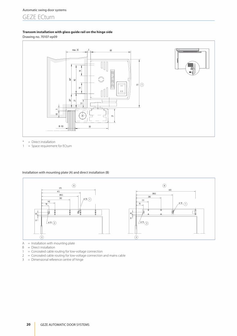
Transom installation with glass guide rail on the hinge sideDrawing no. 70107-ep09
* = Direct installation1 = Space requirement for ECturn
Installation with mounting plate (A) and direct installation (B)
A = Installation with mounting plateB = Direct installation1 = Concealed cable routing for low-voltage connection2 = Concealed cable routing for low-voltage connection and mains cable3 = Dimensional reference centre of hinge
A B
ø 16
ø 16
ø 16 ø 16
1230
78
390.5
142
575
415
302
1428
131
633
266
78
390.5
2 2
3 3
1
1
8-10
1
12
72
1616
50
21
60max. 35 5
105
2120*
4244*
20
Automatic swing door systems
GEZE ECturn
GEZE AUTOMATIC DOOR SYSTEMS

Transom installation with glass guide rail on the opposite hinge sideDrawing no. 70107-ep19
* = Direct installation1 = Space requirement for ECturnLT = Soffit depth
Installation with mounting plate (A) and direct installation (B)
A = Installation with mounting plateB = Direct installation1 = Concealed cable routing for low-voltage connection2 = Concealed cable routing for low-voltage connection and mains cable3 = Dimensional reference centre of hinge
A B
ø 16ø 16
22
3 3
11
130
142
575
415
302
78
390.5
328
78
390.5
131
633
266
1
9
45
109*8
61
508- 10
21
1616
5LT=max.40min.15
5
60
42
44*
21
Automatic swing door systems
GEZE ECturn
Swing Door Systems
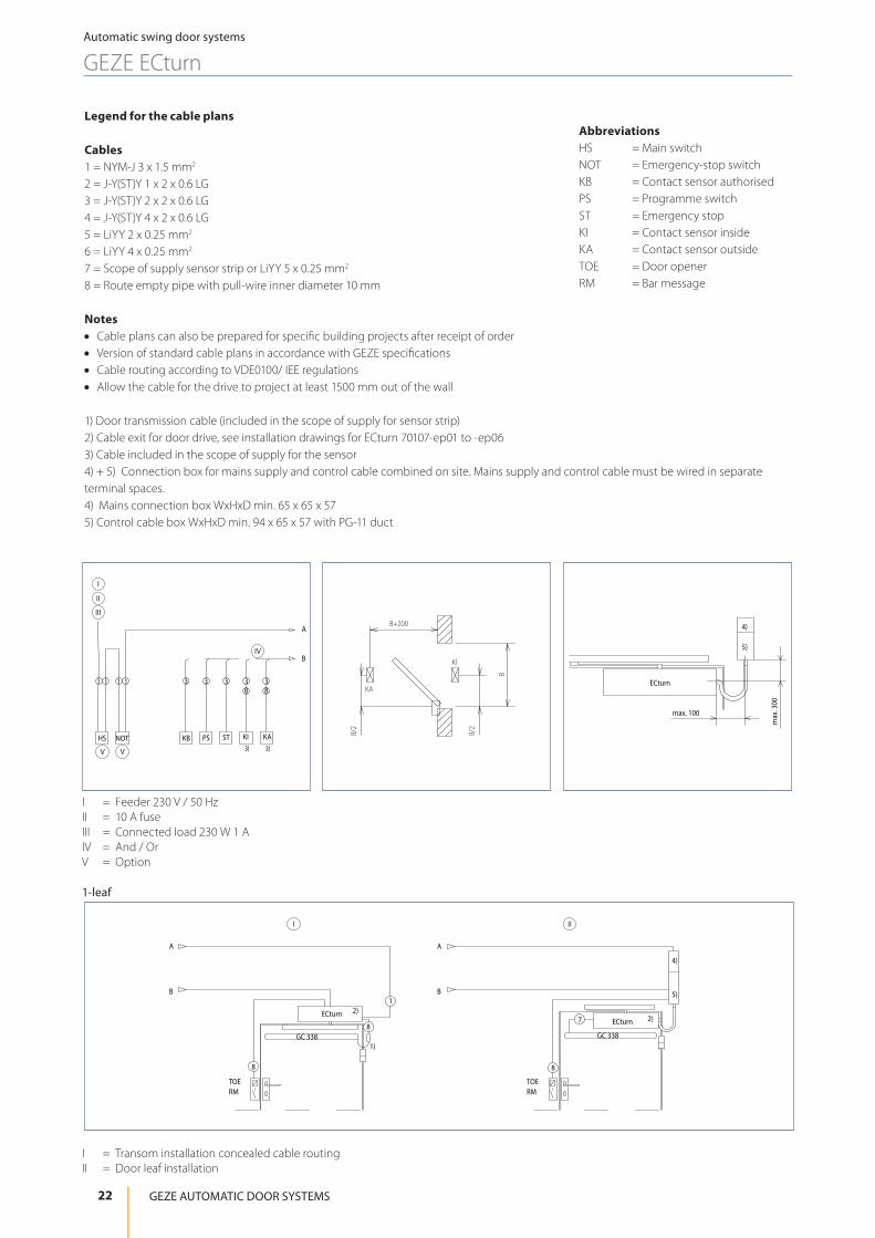
Legend for the cable plans
Cables1 = NYM-J 3 x 1.5 mm2
2 = J-Y(ST)Y 1 x 2 x 0.6 LG3 = J-Y(ST)Y 2 x 2 x 0.6 LG4 = J-Y(ST)Y 4 x 2 x 0.6 LG5 = LiYY 2 x 0.25 mm2
6 = LiYY 4 x 0.25 mm2
7 = Scope of supply sensor strip or LiYY 5 x 0.25 mm2
8 = Route empty pipe with pull-wire inner diameter 10 mm
Notes • Cable plans can also be prepared for specific building projects after receipt of order • Version of standard cable plans in accordance with GEZE specifications • Cable routing according to VDE0100/ IEE regulations • Allow the cable for the drive to project at least 1500 mm out of the wall
1) Door transmission cable (included in the scope of supply for sensor strip)2) Cable exit for door drive, see installation drawings for ECturn 70107-ep01 to -ep063) Cable included in the scope of supply for the sensor4) + 5) Connection box for mains supply and control cable combined on site. Mains supply and control cable must be wired in separate terminal spaces.4) Mains connection box WxHxD min. 65 x 65 x 575) Control cable box WxHxD min. 94 x 65 x 57 with PG-11 duct
3)3)KA
388
31 11 1
KB
3
KI
3
ST
3
PS
B
A
HS NOT
I
II
III
IV
VV
I = Feeder 230 V / 50 HzII = 10 A fuseIII = Connected load 230 W 1 AIV = And / OrV = Option
B+200
B/2
B
B/2
KI
KAECturn
max. 100
max
. 300
4)
5)
1-leaf
I = Transom installation concealed cable routingII = Door leaf installation
AbbreviationsHS = Main switchNOT = Emergency-stop switchKB = Contact sensor authorisedPS = Programme switchST = Emergency stopKI = Contact sensor insideKA = Contact sensor outsideTOE = Door openerRM = Bar message
7
88
A
B
A
B 5)
4)
RMTOE
12)
1)
8
RMTOE
2)
GC 338 GC 338
ECturnECturn
I II
22
Automatic swing door systems
GEZE ECturn
GEZE AUTOMATIC DOOR SYSTEMS

GEZE swing door drive ECturn Inside
Electromechanical swing door drive for 1-leaf single-action doors as „entry door solution“ and inside
With the ECturn Inside swing door drive, GEZE combines accessibility and safety with optimum door design. Thanks to its small dimensions, the drive can be integrated into the door leaf of internal doors (min. thickness 55 mm). The ECturn Inside opens and closes doors “invisibly” without compromising their appearance. The wide range of special functions such as radio push buttons, mobile radio remote control units or acoustic signals allow the system to be tailored to specific user requirements. ECturn Inside can be operated in low-energy and automatic modes. In low-energy mode the drive moves the swing door at reduced speed, thus fulfilling the safety level of DIN 18650 and EN 16005. An optional rechargeable battery provides a safeguard in the event of a power failure ensuring that the door continues to open automatically and safely. The door can also be opened manually in the event of a power failure.
GEZE ECturn InsideDrawing shows installation in wooden door leaf, door frame is reversed (mirror-image)
GEZE ECturn InsideDrawing shows installation in metal door leaf, door frame is reversed (mirror-image)
Application range • Barrier-free entrance doors and internal doors • Hotels and gastronomy • Hospitals and nursing homes for the elderly • Educational institutions, e.g. schools, nursery schools, day care centres • Leisure facilities, e.g. baths, thermal baths, sport and wellness centres • Administration and public buildings • Homes
12.5*20
45
16
66.5
16
87
608.5
65
491
16
47384
302.5285
84
11
45
2012.5*
566306
61 61
12
457
(69)
(5.4
)
11
77
77
23
Automatic swing door systems
GEZE ECturn Inside
Swing Door Systems

X = Door width (mm)Y = Door weight (kg)1 = Area of application in low-energy mode2 = Area of application in automatic mode
Technical data
Product features GEZE ECturn InsideHeight 61 mmWidth 566 mmDepth 45 mmLeaf weight (max.) 1-leaf 125 kgLeaf width (min.-max.) 700 – 1100 mmDrive type ElectromechanicalDoor opening angle (max.)* 110 °DIN left ●DIN right ●Installation in the door leaf ●Installation in the door frame ●Electrical latching action ●Activation delay (max.) 10 SSupply voltage Power supply: 110 - 230 VOperating voltage Drive: 24.5 - 30 V DCCapacity rating 75 WPower supply for external consumers (24 V DC) 600 mATemperature range -15 – 50 °CIP rating IP 20Operating modes Off, Automatic, Permanently open, NightType of function Fully automaticAutomatic function ●Low-energy function ●Key function ●Obstruction detection ●Automatic reversing ●Push & Go adjustableOperation Programme switch integrated in the drive, Keypad programme switch TPSParameter setting Control, Display programme switch DPSApprovals DIN 18650, EN 16005● = Yes* = Depending on the type of installationNOTE: THE MAXIMUM POSSIBLE LEAF WEIGHT IN RELATION TO LEAF WIDTH CAN BE FOUND IN THE CHAPTER ON AREAS OF APPLICATION (DIAGRAMS)!
Areas of application
NoteIn low-energy mode the drive moves the swing door at reduced speed, thus fulfilling the safety requirement in DIN 18650 / EN 16005. The use of safety sensors to safeguard the system is only necessary in individual cases, taking the user group into account. In automatic mode, however, the swing area of the door must always be safeguarded with safety sensors.
0
20
40
60
80
100
120
140
600 700 800 900 1000 1100 X
Y
2
1
24
Automatic swing door systems
GEZE ECturn Inside
GEZE AUTOMATIC DOOR SYSTEMS

Overview of components
1 = Cover for the motor drive control2 = Back check3 = Guide rail and lever4 = Separate programme switch (optional)5 = Fixture for rechargeable battery (optional)6 = Rechargeable battery (optional)7 = Control
Installation in the wooden door frameDrawing no. 70107-ep10
A = Frame cut-outB = Door cut-out1 = Recess for programme switch (optional)2 = Recess for lever* = Dimensions or positions can deviate depending on the door type.
8 = Motor drive control9 = Supply cable, inside door 2.5 m10 = Electric installation material11 = Cable transition (optional)12 = Supply cable (on site)13 = Power supply (flush-mounted)
Z
3
20
R8.5 Z
458
19.5*
113
12
113
46
566 6.5*
(61.
5)
R10 R1027
14
38*
69.5
13.5
*
591*
6.5*
(832)
13
67.5
2
1
Ø
A B
25
Automatic swing door systems
GEZE ECturn Inside
Swing Door Systems

Installation in the wooden door frameDrawing no. 70107-ep13
A = Cut-out for driveB = Door cut-out1 = Cut-out for lever* = Dimensions or positions can deviate depending on the door type.
Installation in the metal door leafDrawing no. 70107-ep12
A = Frame cut-outB = Door leaf cut-out1 = Cut-out for programme switch (optional)* = Dimensions or positions can deviate depending on the door type.
Installation in the metal door frameDrawing no. 70107-ep14
A = Frame cut-outB = Door cut-out* = Dimensions or positions can deviate depending on the door type.
A B
1
61*
113 566
46 7*
R10
Z
3
20
R8.5
Z
61.5
*
458 20*113
564 *
5*
18.5
*
A B
Z9
20
5
R 7.53.5Z
115 455
473
75*
27.5
*
Y
830 46
10
R 5
3.5(6x)
Y
8
10.5133.5
265
20
282
285
30
4646 21123.5
(75)
(839)
302.5
22
65.4
ØØ
1
A B
Z
830 46 R 5
3.5(6x)
Z
830
133.5
10.5
46 21
302.5
20
285123.5282265
(75)46
Y
205
9
R7.5 3.5(2x)Y
473
115 455
(75)
(839)
27.5
*
Ø
Ø
26
Automatic swing door systems
GEZE ECturn Inside
GEZE AUTOMATIC DOOR SYSTEMS

Notes • This cable plan is a simplified symbolic illustration. Connections must be taken from the wiring diagram. Cable routing is included in
the VDE guidelines. • Positioning of the activation and operating devices must be specified on site • Positions shown with dotted lines are positioned on the opposite side • In compliance with DIN 18650 / EN 16005 for automatic mode sensor strips on both sides
Legend for the cable plan1 = NN YM-J 3x1.5 mm²2 = JJ-Y(ST) Y 2x2x0.6 mm²10 = Empty pipe Ø 10 mm with pull-wire; cable supplied by GEZE, max. 3 m11 = Cable information must be provided on site
13 = J-Y(ST) Y 2x2x0,6 mm²; optional empty pipe Ø 10 mm with pull-wire16 = Empty pipe Ø 10 mm with pull-wire; J-Y(ST)Y 4x0.6mm LG17 = Empty pipe Ø 12 mm with pull-wire; NYM-O 2x1.5mm218 = Cable supplied by GEZE, cable length max. 3 mi = Cable consolidation for control/activation devices (symbolic)RSK = Lock switch contact
Entry door, private home, Stuttgart, Germany (Photo: GEZE GmbH)
Standardkabelplan Maximalumfang, einseitig ziehend, 1-flügelig, DIN rechts
27
Automatic swing door systems
GEZE ECturn Inside
Swing Door Systems

GEZE swing door drive Slimdrive EMD
Electromechanical swing door drive for 1 and 2-leaf single-action doors
The electromechanical swing door drive GEZE Slimdrive EMD stands out due to its numerous areas of application. The compact drive is only 7 cm high and can move large and heavy internal and external doors comfortably and quietly. This makes the Slimdrive EMD the ideal solution wherever efficiency has to be coupled with silent running. State-of-the-art control technology combined with a low-wear and maintenance-free high-power motor guarantees reliable operation even for doors which are heavily frequented. All door parameters e.g. opening and closing speed as well as latching action, can be optimally adapted. Manual door opening can be supported by the drive (servo function) and ensures that even heavy doors can be opened more easily manually. The push & go function can be activated on request, i.e. the door is only slightly opened by hand and the automatic activation opens the door completely. In low-energy mode, the drive moves the door at reduced speed. The optional CAN interface can be used to meet demanding requirements e.g. control units for interlocking door systems.
GEZE Slimdrive EMD
71030
8 121650
7211
3
Application range • Internal and external doors • Railway stations and airports • Hotels and gastronomy • Hospitals and nursing homes for the elderly • Educational institutions e.g. schools, nursery schools, day care centres • Leisure facilities, e.g. baths, thermal baths, sport and wellness centres • Administration and public buildings • Food industry
28
Automatic swing door systems
GEZE SLIMDRIVE EMD
GEZE AUTOMATIC DOOR SYSTEMS
Technical data
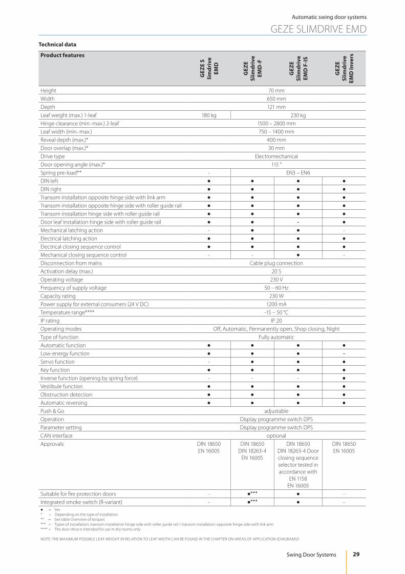
Product features
GEZ
E S
limdr
ive
EMD
GEZ
E Sl
imdr
ive
EMD
-F
GEZ
E Sl
imdr
ive
EMD
F-I
S
GEZ
E Sl
imdr
ive
EMD
Inve
rs
Height 70 mmWidth 650 mmDepth 121 mmLeaf weight (max.) 1-leaf 180 kg 230 kgHinge clearance (min.-max.) 2-leaf 1500 – 2800 mmLeaf width (min.-max.) 750 – 1400 mmReveal depth (max.)* 400 mmDoor overlap (max.)* 30 mmDrive type ElectromechanicalDoor opening angle (max.)* 115 °Spring pre-load** - EN3 – EN6DIN left ● ● ● ●DIN right ● ● ● ●Transom installation opposite hinge side with link arm ● ● ● ●Transom installation opposite hinge side with roller guide rail ● ● ● ●Transom installation hinge side with roller guide rail ● ● ● ●Door leaf installation hinge side with roller guide rail ● ● - ●Mechanical latching action - ● ● -Electrical latching action ● ● ● ●Electrical closing sequence control ● ● ● ●Mechanical closing sequence control - - ● -Disconnection from mains Cable plug connectionActivation delay (max.) 20 SOperating voltage 230 VFrequency of supply voltage 50 – 60 HzCapacity rating 230 WPower supply for external consumers (24 V DC) 1200 mATemperature range**** -15 – 50 °CIP rating IP 20Operating modes Off, Automatic, Permanently open, Shop closing, NightType of function Fully automaticAutomatic function ● ● ● ●Low-energy function ● ● ● -Servo function - ● ● ●Key function ● ● ● ●Inverse function (opening by spring force) - - - ●Vestibule function ● ● ● ●Obstruction detection ● ● ● ●Automatic reversing ● ● ● ●Push & Go adjustableOperation Display programme switch DPSParameter setting Display programme switch DPSCAN interface optionalApprovals DIN 18650
EN 16005DIN 18650
DIN 18263-4EN 16005
DIN 18650DIN 18263-4 Door closing sequence selector tested in accordance with
EN 1158EN 16005
DIN 18650EN 16005
Suitable for fire protection doors - ●*** ● -Integrated smoke switch (R-variant) - ●*** ● -● = Yes* = Depending on the type of installation** = See table Overview of torques*** = Types of installation: transom installation hinge side with roller guide rail / transom installation opposite hinge side with link arm**** = The door drive is intended for use in dry rooms only
NOTE: THE MAXIMUM POSSIBLE LEAF WEIGHT IN RELATION TO LEAF WIDTH CAN BE FOUND IN THE CHAPTER ON AREAS OF APPLICATION (DIAGRAMS)!
29
Automatic swing door systems
GEZE SLIMDRIVE EMD
Swing Door Systems

Overview of torques Slimdrive EMD-F
Type of Installation Transom Installation hinge side (min.-max.)
Door leaf Installation hinge side (min.-max.)
Transom Installation opposite hinge side (min.-max.)
Linkage element roller guide rail roller guide rail roller guide rail link armSpring pre-load Closer size EN 1154 4 - 5 5 3 - 5 4 - 6
Closing torques 20 - 45 Nm 17 - 43 Nm 20 - 45 Nm 35 - 70 NmOpening torques, automa-tic 122 - 97 Nm 125 - 96 Nm 115 - 90 Nm max. 150 Nm
Opening torques, manual 45 - 66 Nm 50 - 73 Nm 42 - 65 Nm 61 - 88 NmNote: For automatic mode, the doors must be equipped with suitable hinges. A door stop is necessary.For fire protection doors only the following types of installation: transom installation hinge side with roller guide rail / transom installation opposite hinge side with link arm
EMD, EMD-F, EMD Invers
1-leaf doors Leaf width (min.) Leaf width (max.)Transom installation hinge side with guide rail 850 mm 1250 mm / 1400* mmTransom installation opposite hinge side with guide rail 850 mm 1250 mm / 1400* mmTransom installation opposite hinge side with link arm 750 mm 1400 mm* Not suitable for fire protection doors!
EMD, EMD-F, EMD F-IS, EMD Invers
2-leaf doors Hinge clearance (min.)
Hinge clearance (max.)
Leaf width (min.) active leaf /
fixed leaf
Leaf width (max.)
Transom installation hinge side / opposite hinge side with guide rail 1700 mm 2500 / 2800* mm 850 mm 1250 / 1400* mm
Transom installation opposite hinge side with link arm 1500 mm 2500 / 2800* mm 750 mm 1250 / 1400* mm* Not suitable for fire protection doors!
30
Automatic swing door systems
GEZE SLIMDRIVE EMD
GEZE AUTOMATIC DOOR SYSTEMS

Areas of application
NoteIn low-energy mode the drive moves the swing door at reduced speed, thus fulfilling the safety requirement in DIN 18650 / EN 16005. The use of safety sensors to safeguard the system is only necessary in individual cases, taking the user group into account. In automatic mode, however, the swing area of the door must always be safeguarded with safety sensors.
Slimdrive EMD
0
20
40
60
80
100
120
140
160
180
200
220
240
700 800 900 1000 1100 1200 1300 1400
1 2
Y
X
X = Door width (mm)Y = Door weight (kg)1 = Link arm2 = Roller guide rail
Slimdrive EMD-F
X = Door width (mm)Y = Door weight (kg)1 = Link arm2 = Roller guide rail3 = Use of fire protection limit for roller guide rail
NoteWe recommend the use of link arms for external doors. Wind loads and underpressure or excess pressure must also be taken into account. Dimensions marked by an asterisk (*) are valid for direct attachment.
Note: Diagram shows left-hand (ISO 6), right-hand (ISO 5) is reversed (mirror-image).
0
20
40
60
80
100
120
140
160
180
200
220
240
700 800 900 1000 1100 1200 1300 1400
1
2
3
X
Y230
31
Automatic swing door systems
GEZE SLIMDRIVE EMD
Swing Door Systems
Installation with mounting plate (A) and direct installation (B)
A B
620577
394256
7330
max
. 20
89 698
1
2
3
max
. 20
4
620540
412274
3014
max. 20
4
1
2
3
89 698
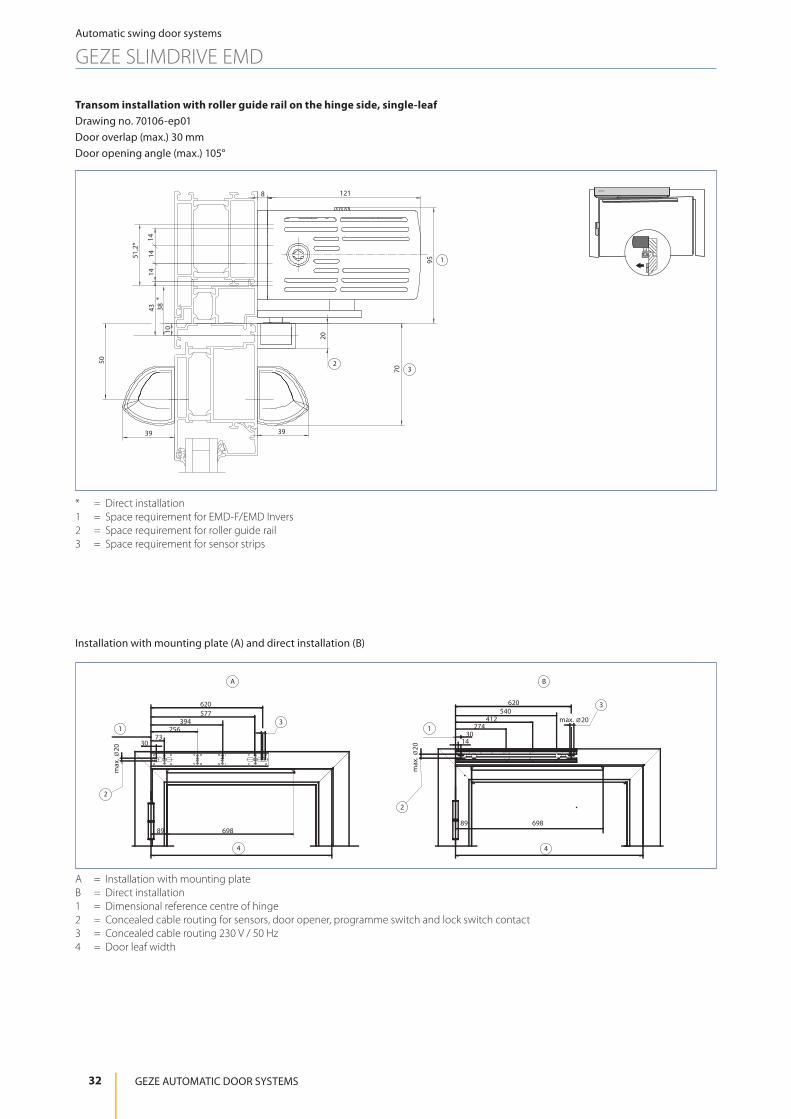
A = Installation with mounting plateB = Direct installation1 = Dimensional reference centre of hinge2 = Concealed cable routing for sensors, door opener, programme switch and lock switch contact3 = Concealed cable routing 230 V / 50 Hz4 = Door leaf width
Transom installation with roller guide rail on the hinge side, single-leafDrawing no. 70106-ep01 Door overlap (max.) 30 mmDoor opening angle (max.) 105°
* = Direct installation1 = Space requirement for EMD-F/EMD Invers2 = Space requirement for roller guide rail3 = Space requirement for sensor strips
1218
95
1414
1443
10
50
20
70
3939
51,2
*
38
1
23
*
32
Automatic swing door systems
GEZE SLIMDRIVE EMD
GEZE AUTOMATIC DOOR SYSTEMS

Installation with mounting plate (A) and direct installation (B)
598577
394256
7352
82698
12
3
A
636598
376238
11052
max. Ø 20
698 82
max
. Ø 2
0
B
1
4
2
3
max. Ø 20
max
. Ø 2
0
A = Installation with mounting plateB = Direct installation1 = Dimensional reference centre of hinge2 = Concealed cable routing for sensors, door opener, programme switch and lock switch contact3 = Concealed cable routing 230 V / 50 Hz4 = Door leaf width
Transom installation with roller guide rail on the opposite hinge side, single-leafDrawing no. 70106-ep02Reveal depth (max.) -30 to +50 mmDoor opening angle (max.) 105°
* = Direct installation1 = Space requirement for EMD-F/EMD Invers2 = Space requirement for roller guide rail3 = Space requirement for sensor strips
1218
9075
39
39 39
70
29
1414
1443
51,2
*38
*
1
3
2
33
Automatic swing door systems
GEZE SLIMDRIVE EMD
Swing Door Systems

Installation with mounting plate (A) and direct installation (B)
1
2
3
4
598577
394256
7352
44 417
max
. Ø 2
0
max. Ø 201
2
3
4
max
. Ø 2
0
636376
238110
52
41744
max. Ø 20
A B
A = Installation with mounting plateB = Direct installation1 = Dimensional reference centre of hinge2 = Concealed cable routing for sensors, door opener, programme switch and lock switch contact3 = Concealed cable routing 230 V / 50 Hz4 = Door leaf width
Transom installation with link arm on the opposite hinge side, single-leaf Drawing no. 70106-ep03Reveal depth (max.) 0-100 mm, 100-200 mm, 200-300 mmDoor opening angle (max.) 110°
* = Direct installation1 = Space requirement for EMD-F/EMD Invers2 = Space requirement for link arm3 = Space requirement for sensor strips
1218
95
75
47
39 39
75
4814
1414
34
51,2
*
43*
1
3
2
34
Automatic swing door systems
GEZE SLIMDRIVE EMD
GEZE AUTOMATIC DOOR SYSTEMS

Door leaf installation with roller guide rail on the hinge side, single-leaf Drawing no. 70106-ep04Door overlap (max.) 30 mmDoor opening angle (max.) 115°
* = Direct installation1 = Space requirement for EMD-F/EMD Invers2 = Space requirement for roller guide rail3 = Space requirement for sensor strips
Installation with mounting plate (A) and direct installation (B)
Ø 20
69 748
82
666628
406268
140
69 748
82
628607
424286
103
Ø 20
A B
22
4 4
3 3
11 Ø 20Ø 20
A = Installation with mounting plateB = Direct installation1 = Dimensional reference centre of hinge2 = Concealed cable routing for sensors, door opener, programme switch and lock switch contact3 = Concealed cable routing 230 V / 50 Hz4 = Door leaf width
3939
100
8
120
29 3970
4314
1414
121
38 *
51.2
* 1
2
33
35
Automatic swing door systems
GEZE SLIMDRIVE EMD
Swing Door Systems

Installation with mounting plate (A) and direct installation (B)
89 698 89698
1430
274412
540620
662
14
662
540620
412274
30
8969889 698
30
721620
577394
25673
30
577620
721
394256
73
Ø 20
Ø 20
Ø 20
Ø 20
B
A
2
1
3
1
3
1
144
4 4
5
5
2
A = Installation with mounting plateB = Direct installation1 = Dimensional reference centre of hinge2 = Concealed cable routing for sensors, door opener, programme switch and lock switch contact3 = Concealed cable routing 230 V / 50 Hz4 = Door leaf width5 = Hinge clearance
Transom installation with roller guide rail on the hinge side, double-leafDrawing no. 70106-ep21
1218
95
1414
1443
10
50
20
703939
51,2
*
38*
1
23
* = Direct installation1 = Space requirement for EMD-F/EMD Invers2 = Space requirement for roller guide rail3 = Space requirement for sensor strips
36
Automatic swing door systems
GEZE SLIMDRIVE EMD
GEZE AUTOMATIC DOOR SYSTEMS

Transom installation with roller guide rail on the opposite hinge side, double-leafDrawing no. 70106-ep22
1218
9072
3939 39
70
29
1414
1443
51,2
*38
*
1
3
2
* = Direct installation1 = Space requirement for EMD-F/EMD Invers2 = Space requirement for roller guide rail3 = Space requirement for sensor strips
Installation with mounting plate (A) and direct installation (B)
8269882 698
394577
598
5273
256
721 721
5273
256394
577598
698 8282 698
662
52
376238
110
636598
662636
52
376238
110
598
A
B
1
2
2
3
4 4
4
5
5
Ø 20
Ø 20
Ø 20
Ø 20
31
1
1
4
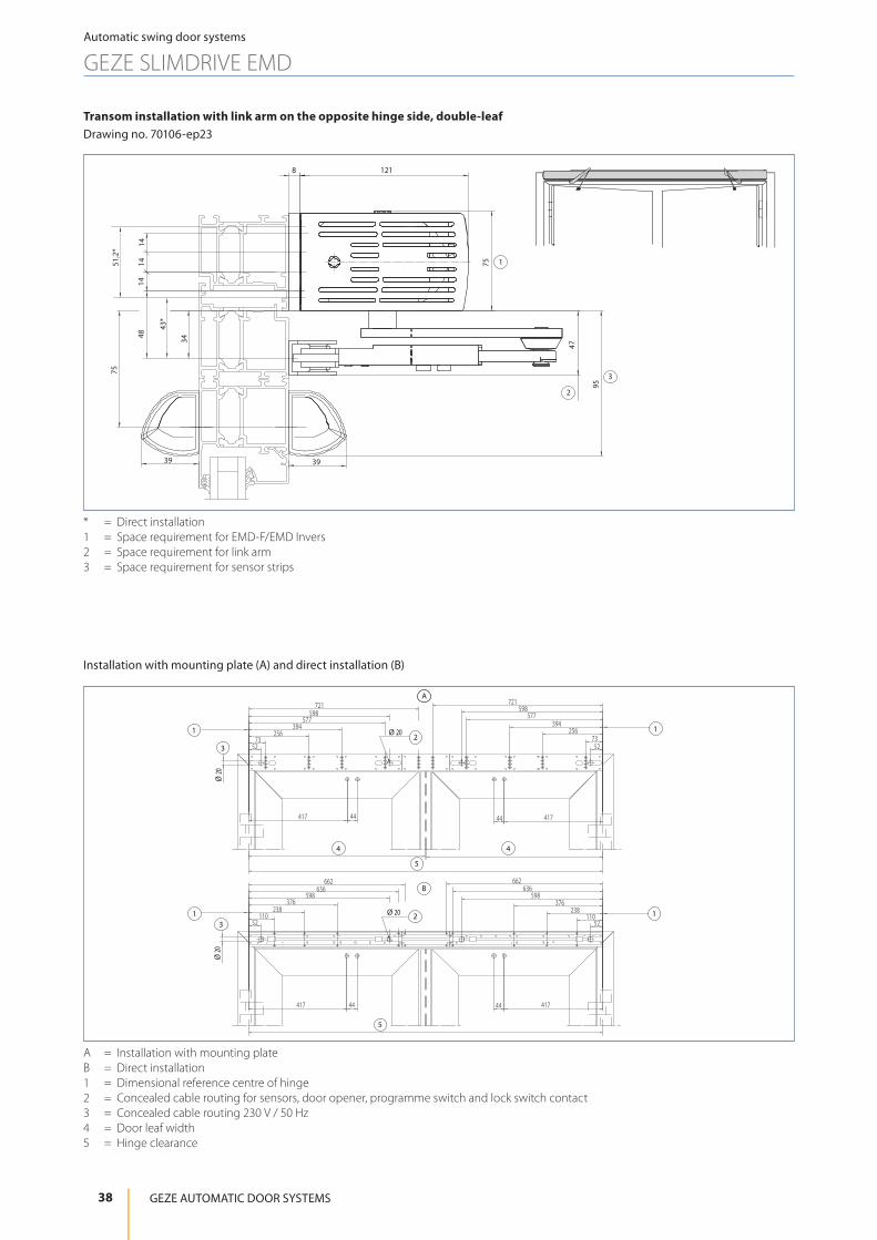
A = Installation with mounting plateB = Direct installation1 = Dimensional reference centre of hinge2 = Concealed cable routing for sensors, door opener, programme switch and lock switch contact3 = Concealed cable routing 230 V / 50 Hz4 = Door leaf width5 = Hinge clearance
37
Automatic swing door systems
GEZE SLIMDRIVE EMD
Swing Door Systems
Installation with mounting plate (A) and direct installation (B)
417 44 41744
636662
598
110238
376
52
636662
598
110238
376
52
417 44 41744
52
721
256394
577598
7352
721598
577394
25673
A
B
1
1 1
1Ø 20
Ø 20
Ø 20
Ø 20
2
2
3
3
4 4
5
5
A = Installation with mounting plateB = Direct installation1 = Dimensional reference centre of hinge2 = Concealed cable routing for sensors, door opener, programme switch and lock switch contact3 = Concealed cable routing 230 V / 50 Hz4 = Door leaf width5 = Hinge clearance
Transom installation with link arm on the opposite hinge side, double-leafDrawing no. 70106-ep23
1218
95
75
47
39 39
75
4814
1414
34
51,2
*
43*
1
3
2
* = Direct installation1 = Space requirement for EMD-F/EMD Invers2 = Space requirement for link arm3 = Space requirement for sensor strips
38
Automatic swing door systems
GEZE SLIMDRIVE EMD
GEZE AUTOMATIC DOOR SYSTEMS

Door leaf installation with roller guide rail on the hinge side, double-leaf Drawing no. 70106-ep24
3939
100
8
120
29 3970
4314
1414
121
38*
51.2*
1
2
33
* = Direct installation1 = Space requirement for EMD-F/EMD Invers2 = Space requirement for roller guide rail3 = Space requirement for sensor strips
Installation with mounting plate (A) and direct installation (B)
6974869 748
82
628607
424286
10382
628607
424286
103
69 748 69748
82
666
406628
268140
82
666628
406268
140
A
B
1
1
1
1
Ø 20
Ø 20
2
2
3
3
Ø 20
Ø 20
4 4
4 4
5
5
A = Installation with mounting plateB = Direct installation1 = Dimensional reference centre of hinge2 = Concealed cable routing for sensors, door opener, programme switch and lock switch contact3 = Concealed cable routing 230 V / 50 Hz4 = Door leaf width5 = Hinge clearance
39
Automatic swing door systems
GEZE SLIMDRIVE EMD
Swing Door Systems

Legend for the cable diagrams
Cable1 = NYM-J 3 x 1.5 mm2
2 = J-Y(ST)Y 1 x 2 x 0.6 LG3 = J-Y(ST)Y 2 x 2 x 0.6 LG4 = J-Y(ST)Y 4 x 2 x 0.6 LG5 = LiYY 2 x 0.25 mm2
6 = LiYY 4 x 0.25 mm2
7 = Scope of supply sensor strip or LiYY 5 x 0.25 mm2
8 = Route empty pipe with pull-wire inner diameter 10 mm
Notes • Cable diagrams can also be prepared for specific building projects after receipt of order • Version of standard cable diagrams in accordance with GEZE specifications • Cable routing according to VDE0100/ IEE regulations • Allow the cable for the drive to project at least 1500 mm out of the wall
1) Door transmission cable (including in the scope of supply for sensor strip), cable routing through a hole in the door leaf is not permitted for fire protection doors.2) Cable exit for door drive, see installation drawings for Slimdrive EMD/EMD-F 70106-ep01 to -ep043) Cable including in the scope of supply for the sensor4) Install in the direct vicinity of the door5) Mains connection box WxHxD min. 65 x 65 x 57 with PG-11 duct, on site6) Low-voltage connection box WxHxD min. 94 x 65 x 57 with PG-11 duct, on site7) E.g. door transmission cable, 8-wire, art. no. 0669228) Branch box, on site
AbbreviationsHS = Main switchNOT = Emergency-stop switchUT = Circuit breaker CLOSE DOOR (only with F variant)KB = Contact sensor authorisedPS = Programme switchST = Emergency stopKI = Contact sensor insideKA = Contact sensor outsideTOE = Door openerRM = Bar messageRS = Smoke switch (only with F variant)RSZ = Smoke switch control unit (only with F variant)TS = Door closerMK = Magnetic contact
40
Automatic swing door systems
GEZE SLIMDRIVE EMD
GEZE AUTOMATIC DOOR SYSTEMS

I = Feeder 230 V / 50 HzII = 10 A fuseIII = Connected value 230 W, 1 A 1-, 2-leaf with manual fixed leaf; connected value 460 W, 1 A with 2-leafIV = And / OrV = Option
B+200
B/2
B
B/2
KI
KA
max. 100
max
. 300
5)
6)
EMD/EMD-F
1-leaf
RS 3 3RSRS 33RS
7
88
8)
C
A
B
D
C
A
B
D
3 3
6)
5)1RSZ
RMTOE
1
12
RSZ
2)
1)
8
RMTOE
2)
GC 338 GC 338
EMD/EMD-FEMD/EMD-F
I II
2-leaf
8
D*83
2)2)2)
*
83
1
D
7
7
C
A
B
DC
A
B
D
6
1
6)
5)
6)
5)
RM
3
1
TOE
RSZ
RMTOE
RM
3
1
1TOE
2
RSZ
2)
1)
8
RMTOE
8)
8
8
7)
4
7
RS 3 3RSRS 3 3RS
6
GC 338 GC 338 GC 338 GC 338
III IVIII IV
EMD/EMD-F
I II
EMD/EMD-F EMD/EMD-F EMD/EMD-F
I = Transom installationII = Door leaf installationIII = Fixed leafIV = Active leaf
3)3)KA
388
3221 11 1
KB
3
KI
3
ST
3
PS
D/D*
BA
C
HS NOT UT4)
III
II
I
IV
VV
41
Automatic swing door systems
GEZE SLIMDRIVE EMD
Swing Door Systems

GEZE swing door drive TSA 160 NT
Electrohydraulic swing door drive for 1 and 2-leaf single-action doors
The TSA 160 NT is an electronically controlled hydraulic swing door system for single-action doors made of wood, steel, aluminium or plastic with leaf weights of up to 310 kg and leaf widths of up to 1600 mm. The drive works with a hydraulic pump system during opening. The closing process is by means of a closing spring mechanism and adjustable hydraulic valves. The TSA 160 NT also has low power consumption and is low-maintenance. The door can be opened by hand in the event of a power failure. Manual opening is also possible with motor operation switched on. A reinforced and highly stable link arm meets the requirements of large and heavy doors which are highly frequented. The TSA 160 NT masters large amounts of foot traffic reliably and easily.
GEZE TSA 160 NT
690
150
100
1218
30465
Application range • Internal and external doors • Railway stations and airports • Hotels and gastronomy • Hospitals and nursing homes for the elderly • Department stores and shopping centre • Educational institutions e.g. schools, nursery schools, day care centres • Leisure facilities, e.g. baths, thermal baths, sport and wellness centres • Administration and public buildings • Food industry
42
Automatic swing door systems
GEZE TSA 160 NT
GEZE AUTOMATIC DOOR SYSTEMS

Technical data
Product features
GEZ
E TS
A 1
60 N
T
GEZ
E TS
A 1
60 N
T In
vers
GEZ
E TS
A 1
60 N
T IS
GEZ
E TS
A 1
60 N
T EN
7
GEZ
E TS
A 1
60 N
T
IS E
N7
Height 100 mmWidth 690 mmDepth 121 mmLeaf weight (max.) 1-leaf 250 kg 310 kgHinge clearance (min.-max.) 2-leaf 1470 – 2800 mm 1470 – 3200 mmLeaf width (min.-max.) 690 – 1400 mm 690 – 1600 mmReveal depth (max.)* 400 mmDoor overlap (max.)* 20 mmDrive type ElectrohydraulicDoor opening angle (max.)* 115 °Spring pre-load** EN3 – EN6 EN7Z-variant (pulling) ● - ● ● ●Z-variant (pushing) - ● - - -DIN left ● ● ● ● ●DIN right ● ● ● ● ●Transom installation opposite hinge side with link arm
● ● ● ● ●
Transom installation hinge side with roller guide rail
● ● ● ● ●
Mechanical latching action ● - ● ● ●Electrical closing sequence control ● ● ● ● ●Mechanical closing sequence control - - ● - ●Disconnection from mains Not availableActivation delay (max.) 10 SOperating voltage 230 VFrequency of supply voltage 50 – 60 HzCapacity rating 300 W 450 WPower supply for external consumers (24 V DC) 1200 mA
Temperature range*** -15 – 60 °CIP rating IP 20Operating modes Off, Automatic, Permanently open, Shop closing, NightType of function Fully automaticAutomatic function ● ● ● ● ●Key function ● ● ● ● ●Inverse function (opening by spring force) - ● - - -Vestibule function ● ● ● ● ●Obstruction detection ● ● ● ● ●Automatic reversing ● ● ● ● ●Push & Go adjustableOperation Display programme switch DPSParameter setting Display programme switch DPSApprovals DIN 18650, EN 16005Use on fire and smoke protection doors (F-variant)
● - ● ● ●
● = Yes* = Depending on the type of installation** = See table overview of torques*** = The door drive is intended for use in dry rooms only
NOTE: THE MAXIMUM POSSIBLE LEAF WEIGHT IN RELATION TO LEAF WIDTH CAN BE FOUND IN THE CHAPTER ON AREAS OF APPLICATION (DIAGRAMS)!
43
Automatic swing door systems
GEZE TSA 160 NT
Swing Door Systems

pushing (min.-max.) pulling (min.-max.)Spring pre-loadCloser size EN 1154
3 - 67 (with TSA 160 NT EN7)
2 - 5 6 (with TSA 160 NT EN7)
Closer torques:torque exerted by the closing spring during automatic opening
20 Nm - >60 Nm 8 Nm - 30 Nm
Opening torque:torque exerted by the door during automatic opening
150 Nm - 90 Nm 70 Nm - 40 Nm
Opening torque:manual torque to be exerted for door opening
35 Nm - 110 Nm 13 Nm - 45 Nm
Note: For automatic mode, the doors must be equipped with suitable hinges. A door stop is necessary.
TSA 160 NT minimum and maximum leaf widths
1-leaf doors Leaf width (min.) Leaf width (max.)TSA 160 NT pushing1) 690 mm 1400 mm / 1600 mm2)
TSA 160 NT pulling950 mm (with operator displacement=0)
890 mm (with operator displacement=60 mm)1400 mm / 1600 mm2)
TSA 160 NT Z 690 mm 1400 mm / 1600 mm2)
1) Also on smoke and fire protection doors2) TSA 160 NT EN7
TSA 160 NT minimum and maximum leaf widths, hinge clearance for 2-leaf doors
2-leaf doors Hinge clearance (min.)
Hinge clearance (max.)
Leaf width (min.) active leaf2)
Leaf width (min.) fixed leaf2) Leaf width (max.)
TSA 160 NT IS pushing1) 1470 mm 2800 mm / 3200 mm3) 690 mm 400 mm 1400 mm / 1600 mm2)
TSA 160 NT Z-IS pulling 1470 mm 2800 mm / 3200 mm3) 690 mm 650 mm 1400 mm / 1600 mm2)
TSA 160 NT IS/TS pushing1) 1260 mm 2800 mm / 3200 mm3) 690 mm 400 mm 1400 mm / 1600 mm2)
TSA 160 NT IS/TS pulling 1360 mm 2800 mm / 3200 mm3) 690 mm 650 mm 1400 mm / 1600 mm2)
1) Also on smoke and fire protection doors2) The minimum hinge width must be observed!3) TSA 160 NT IS EN7
Overview of torques TSA 160 NT
44
Automatic swing door systems
GEZE TSA 160 NT
GEZE AUTOMATIC DOOR SYSTEMS

Areas of application
TSA 160 NT EN7
X = Door width (mm)Y = Door weight (kg)1 = Link arm2 = Roller guide rail
TSA 160 NT
X = Door width (mm)Y = Door weight (kg)1 = Link arm2 = Roller guide rail
50
100
150
200
250
300
700 800 900 1000 1100 1200 1300 1400
Y
X
2
1
50
100
150
200
250
300
350
700 800 900 1000 1100 1200 1300 1400 1500 1600 1700
1
2
Y
X
310
45
Automatic swing door systems
GEZE TSA 160 NT
Swing Door Systems
587
625
50
48
186 453
34 420
50
50
587
20
162.5
186 453
325
650487.5
A B
1
1 1 1Ø 20
Ø 20
Ø 20 Ø 20
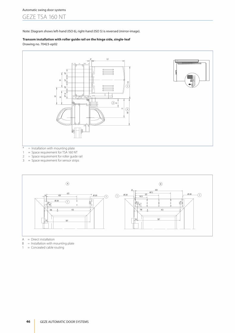
A = Direct installationB = Installation with mounting plate1 = Concealed cable routing
Note: Diagram shows left-hand (ISO 6), right-hand (ISO 5) is reversed (mirror-image).
Transom installation with roller guide rail on the hinge side, single-leafDrawing no. 70423-ep02
* = Installation with mounting plate1 = Space requirement for TSA 160 NT2 = Space requirement for roller guide rail3 = Space requirement for sensor strips
80
31
31
50
119
29*
29*
22*
29*
8* 121
63
54
42
1
2
3
46
Automatic swing door systems
GEZE TSA 160 NT
GEZE AUTOMATIC DOOR SYSTEMS

453 X
1
1 = Mounting plate
TSA 160 NT
Soffit depth L(from-to)
Dimension X for roller guide rail with TSA 160 NT Z Door width (min.) Opening angle
> 0 - 25 mm 186 mm 690 mm 109° - 113°> 25 - 50 mm 192 mm 690 mm 113° - 115°> 50 - 75 mm 203 mm 690 mm 115° - 110°> 75 - 100 mm 215 mm 690 mm 110° - 105°> 100 - 125 mm 229 mm 690 mm 105° - 100°> 125 - 150 mm 244 mm 703 mm 100° - 97°> 150 - 175 mm 262 mm 721 mm 97° - 95°> 175 - 200 mm 280 mm 739 mm 95° - 90°
47
Automatic swing door systems
GEZE TSA 160 NT
Swing Door Systems

587
48
625
50
335
44
34 420
587
44
50
50
335
20 162.5
1029
2229
325
650487.5
Ø 20 Ø 20
Ø 20
Ø 20
A B
1 1
1
1
A = Direct installationB = Installation with mounting plate1 = Concealed cable routing
Transom installation with link arm on the opposite hinge side, single-leaf Drawing no. 70423-ep01
* = Installation with mounting plate1 = Space requirement for TSA 160 NT2 = Space requirement for link arm3 = Space requirement for sensor strips
85
41*
39
4 40
8*121
29*
29*
22*
100
27+X
54
1
2
3
48
Automatic swing door systems
GEZE TSA 160 NT
GEZE AUTOMATIC DOOR SYSTEMS

Transom installation with roller guide rail on the hinge side, double-leafDrawing no. 70423-ep22
50
31
8060
8* 121
2929
*22
*29
*
11954
42
3
2
1
* = Installation with mounting plate1 = Space requirement for TSA 160 NT2 = Space requirement for roller guide rail3 = Space requirement for sensor strips
587
625 625
50
48
3442034 420
186 453
186453
58750
50
186453
20 162.5 20162.5
186 453
325
650487.5
325
B/2650
487.5
A
B
1
1
1
1
2Ø 20
Ø 20
Ø 20
Ø 20
A = Direct installationB = Installation with mounting plate1 = Concealed cable routing2 = only required for B > 2000
49
Automatic swing door systems
GEZE TSA 160 NT
Swing Door Systems

44
335
44
335
587
50
50
B /2
20 162.5 20162.5
487.5650
325
650487.5
325
Ø 20Ø 20
A
B
1 1
2
44
335
44
335
587
48
50
625 625
34 420 34420
Ø 20
Ø 20 1
1
A = Direct installationB = Installation with mounting plate1 = Concealed cable routing2 = only required for B > 2000
Transom installation with link arm on the opposite hinge side, double-leafDrawing no. 70423-ep11
3985
max. 350
X
86
5529
*22
*29
*
8*12110
0
40
5154
1
2
3
X = Spindle extension* = Installation with mounting plate1 = Space requirement for TSA 160 NT2 = Space requirement for link arm3 = Space requirement for sensor strips
50
Automatic swing door systems
GEZE TSA 160 NT
GEZE AUTOMATIC DOOR SYSTEMS

Legend for the cable diagrams
Cable1 = NYM-J 3 x 1.5 mm2
2 = J-Y(ST)Y 1 x 2 x 0.6 LG3 = J-Y(ST)Y 2 x 2 x 0.6 LG4 = J-Y(ST)Y 4 x 2 x 0.6 LG5 = LiYY 2 x 0.25 mm2
6 = LiYY 4 x 0.25 mm2
7 = Scope of supply sensor strip or LiYY 5 x 0.25 mm2
8 = Route empty pipe with pull-wire inner diameter 10 mm
Operator displacement AV = Cable exit60 mm = 580 mm50 mm = 590 mm40 mm = 600 mm (standard)30 mm = 610 mm20 mm = 620 mm10 mm = 630 mm0 mm = 640 mm
Notes • Cable diagrams can also be prepared for specific building projects after receipt of order • Version of standard cable diagrams in accordance with GEZE specifications • Cable routing according to VDE0100/ IEE regulations • Allow the cable for the drive to project at least 1500 mm out of the wall
1) Door transmission cable (including in the scope of supply for sensor strip), cable routing through a hole in the door leaf is not permitted for fire control doors.2) Cable exit for door drive see sketch A and B3) Cable including in the scope of supply for the sensor4) Install in the direct vicinity of the door7) E.g. door transmission cable, 8-wire, art. no. 0669228) Branch box, on site
AbbreviationsHS = Main switchNOT = Emergency-stop switchUT = Circuit breaker CLOSE DOOR (only with F variant)KB = Contact sensor authorisedPS = Programme switchST = Emergency stopKI = Contact sensor insideKA = Contact sensor outsideTOE = Door openerRM = Bar messageRS = Smoke switch (only with F variant)RSZ = Smoke switch control unit (only with F variant)TS = Door closerMK = Magnetic contact
51
Automatic swing door systems
GEZE TSA 160 NT
Swing Door Systems

Positioning of the movement detectors
B/2
B+200 B+200
BWM
B/2
B
BWMB
2xB
B+200
B
KI
KAKA
KI
B/2
B+200
B
I II III
I = Positioning of movement detector 1-leafII = Positioning of movement detector 2-leafIII = Positioning of movement detector 2-leaf, 2E
3)3)
KA
388
3221 11 1
KB
3
KI
3
ST
3
PS
D/D*
BA
C
HS NOT UT
4)
III
II
I
IV
VV
I = Feeder 230 V / 50 HzII = 10 A fuseIII = Connected value 300 W 1.3 A for 1- 2-leaf with manual fixed leaf Connected value 600 W 2.6 A for 2-leafIV = And / OrV = Option
52
Automatic swing door systems
GEZE TSA 160 NT
GEZE AUTOMATIC DOOR SYSTEMS
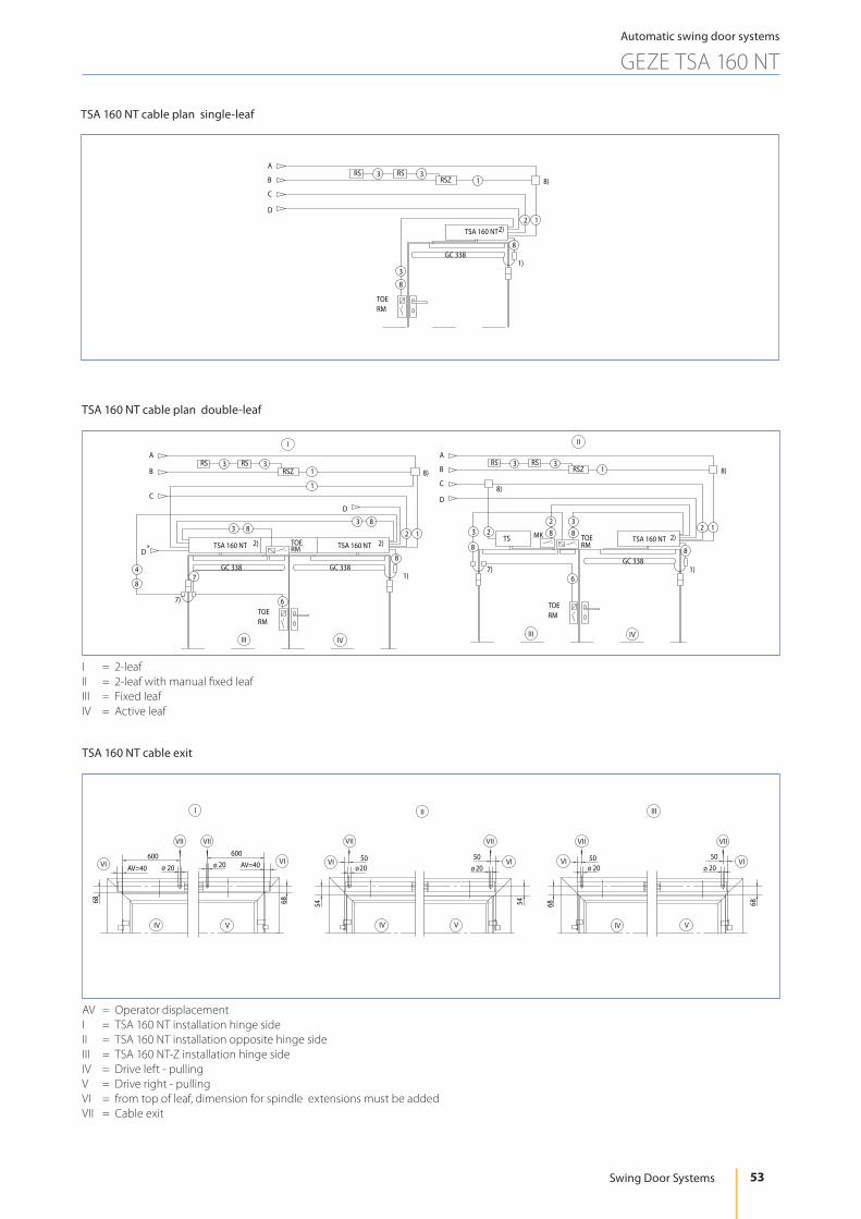
TSA 160 NT cable plan single-leaf
TSA 160 NT
TOERM
8
1)
2)
RSZ
2 1
1
GC 338
3
D
B
A
C
8)
8
RS 3 3RS
TSA 160 NT cable plan double-leaf
6
RS 33RSRS 33RS
82
MK
8)
3
4
7)
8
8)8)
2
C
A
B
D
6
TSRM
1
1TOE
2
7)
RSZ
2)
1)
8
RMTOE
TOERM
8
1)
2)
RSZ
GC 338
2TOE
1
1
3
RMTSA 160 NT
D
B
A
C
7
D
1
3 8
* 2)
8
8
38
GC 338GC 338
I II
TSA 160 NTTSA 160 NT
III IVIII IV
I = 2-leafII = 2-leaf with manual fixed leafIII = Fixed leafIV = Active leaf
TSA 160 NT cable exit
68
ø 20600
AV=40
68
ø 20600
AV=40
IV V
VI VI
VII VII
54
ø2050
54
ø 2050
IV V
VI VI
VII VII
68
50ø 20
68
50ø 20
IV V
VI
VII VII
VI
I II III
AV = Operator displacementI = TSA 160 NT installation hinge sideII = TSA 160 NT installation opposite hinge sideIII = TSA 160 NT-Z installation hinge sideIV = Drive left - pullingV = Drive right - pullingVI = from top of leaf, dimension for spindle extensions must be addedVII = Cable exit
53
Automatic swing door systems
GEZE TSA 160 NT
Swing Door Systems

54
Automatic swing door systems
GEZE POWERTURN
GEZE AUTOMATIC DOOR SYSTEMS
GEZE swing door drive Powerturn
Fully automatic swing door drive for 1 and 2-leaf single-action doors
The swing door drive Powerturn offers comfort and safety for every access situation. The fully automatic drive is powerful and opens even large, heavy doors with leaf weights up to 600 kg at door widths of 930 mm reliably and safely. GEZE’s powerful model is also the perfect solution for fire protection doors with leaf weights up to 600 kg. It offers freedom to design for a wide range of uses. The unique „Smart swing“ function allows for easy manual use even of large, heavy doors, e.g. fire protection doors or façade doors, at any time. The powerful closing spring is once pre-tensioned and does not have to be moved permanently during passage. In addition, the „Smart swing“ function reduces energy costs during operation and in the „permanently open“ position. The small overall height and discreet design make it flexible and future-proof for multifunction safety doors, safe escape and rescue routes and complex interlocking door systems. This makes the Powerturn an excellent example of „Universal Design - made in Germany“. Installation is straightforward and safe due to the simple GEZE installation system.
Area of application • Internal and external doors • Railway stations and airports • Hotels and gastronomy • Hospitals and homes for the elderly • Department stores and shopping centres • Educational institutions, e.g. schools, nursery schools, day care centres • Leisure facilities, e.g. baths, thermal baths, sport and wellness centres • Administration and public buildings • Food industry
GEZE Powerturn

55
Automatic swing door systems
GEZE POWERTURN
Swing Door Systems
Technical data
Product features
GEZ
E
Pow
ertu
rn1-
leaf
/ 2-
leaf
GEZ
E Po
wer
turn
F
GEZ
E Po
wer
turn
F-
IS
GEZ
E Po
wer
turn
F/
R
GEZ
E Po
wer
turn
F/
R-IS
GEZ
E Po
wer
turn
IS
/TS
Height 70 mm
Width 720 mm -
Depth 130 mm
Leaf weight (max.) 1-leaf 600 kg with door widths of 930 mm
Hinge clearance (min.-max.) 2-leaf link arm 1480 – 3200 mm 1270 – 3200 mm
Hinge clearance (min.-max.) 2-leaf roller guide rail 1600 – 3200 mm 1380 – 3000 mm
Leaf width (min.-max.) 800 – 1600 mm 470 – 1600 mm
Reveal depth (max.)* -30 – 560 mm -30 – 300 mm 160 mm
Drive type Electromechanical
Door opening angle (max.)* 136 °
Spring pre-load** EN4 – EN7 EN1 - EN7
DIN left ● -DIN right ● -Transom installation opposite hinge side with link arm ●Transom installation opposite hinge side with roller guide rail ● -Transom installation hinge side with roller guide rail ●Door leaf installation opposite hinge side with roller guide rail ● -Door leaf installation hinge side with roller guide rail ● -Door leaf installation hinge side with link arm ● -Mechanical latching action ●Electrical latching action ● -Electrical closing sequence control ● -Mechanical closing sequence control*** ●Disconnection from mains all pole main switch in the drive
Activation delay (max.) 10 s
Operating voltage 230 V
Frequency of supply voltage 50 – 60 Hz
Capacity rating 200 W
Power supply for external consumers (24 V DC) 1200 mA per drive
Temperature range**** -15 – 50 °C
IP rating IP 30
Operating modes Automatic, Night, Permanently open, Shop closing, Off
Type of function Fully automatic
Automatic function ●Low-Energy function ●Smart swing function ●Key function ●Vestibule function ●Obstruction detection ●Automatic reversing ●Push & Go adjustable
Operation GEZEconnects (PC + Bluetooth), Service terminal ST 220, Display programme switch DPS
Parameter setting GEZEconnects (PC + Bluetooth), Service terminal ST 220, Display programme switch DPS
Approvals DIN 18650, EN 16005,
DIN 18263-4
DIN 18650, EN 16005,
DIN 18263-4
DIN 18650, EN 16005,
DIN 18263-4, Door closing
sequence selector tested in accordance with EN 1158
DIN 18650, EN 16005,
DIN 18263-4
DIN 18650, EN 16005,
Door closing sequence selector tested in accordance with EN 1158
Integrated smoke switch (R-variant) - ● ● ●● = Yes* = Depending on the type of installation ** = See table overview of torques*** = Optional for 2-leaf Systems and transom installation or only for the is variants****= The door drive is intended for use in dry rooms only
NOTE: THE MAXIMUM POSSIBLE LEAF WEIGHT IN RELATION TO LEAF WIDTH CAN BE FOUND IN THE CHAPTER ON AREAS
OF APPLICATION (DIAGRAMS)!

56
Automatic swing door systems
GEZE POWERTURN
GEZE AUTOMATIC DOOR SYSTEMS
Technical data for use of the IS/TS variant
* Standard package with TS 4000 EN 1-6, on request via Customer Solutions there is the option for the use of the GEZE TS 4000 EN 5-7
Element Active leaf Passive leafDrive/door closer GEZE Powerturn (F) (F/R) TS 5000 LLever type Roller guide rail Guide railMin. - max. leaf width 800 - 1600 mm 580 - 1400 mmMin. - max. hinge size 1380 - 3000 mmReveal 0 mmEN closing force EN 4-6 EN 2-6
Element Active leaf Passive leafDrive/door closer GEZE Powerturn (F) (F/R) TS 4000 EN 1-6 or EN 5-7Lever type Link arm Link armMin. - max. leaf width 800 - 1600 mm 470 - 1600 mmMin. - max. hinge size 1270 - 3200 mmReveal 160 mmEN closing force EN 6-7 EN 1-7*
GEZE Powerturn IS/TS with TS 5000 L door closer
GEZE Powerturn IS/TS with TS 4000 door closer
57
Automatic swing door systems
GEZE POWERTURN
Swing Door Systems
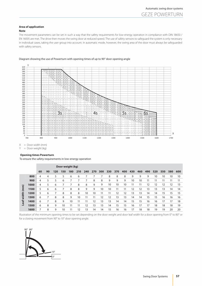
X = Door width (mm) Y = Door weight (kg)
Diagram showing the use of Powerturn with opening times of up to 90° door opening angle
Area of application Note The movement parameters can be set in such a way that the safety requirements for low-energy operation in compliance with DIN 18650 / EN 16005 are met. The drive then moves the swing door at reduced speed. The use of safety sensors to safeguard the system is only necessary in individual cases, taking the user group into account. In automatic mode, however, the swing area of the door must always be safeguarded with safety sensors.
Opening times PowerturnTo ensure the safety requirements in low-energy operation
Illustration of the minimum opening times to be set depending on the door weight and door leaf width for a door opening from 0° to 80° or for a closing movement from 90° to 10° door opening angle.
020406080
100120140160180200220240260280300320340360380400420440460480500520540560580600620
700 800 900 1000 1100 1200 1300 1400 1500 1600 1700
3s 4s 6s 5s
X
Y
Door weight (kg)
60 90 120 150 180 210 240 270 300 330 370 400 430 460 490 520 550 580 600
800 4 4 5 5 6 6 7 7 7 8 8 8 9 9 9 10 10 10 10900 4 5 5 6 7 7 7 8 8 9 9 9 10 10 11 11 11 11 11
1000 4 5 6 7 7 8 8 9 9 10 10 10 11 11 12 12 12 12 13
1100 5 6 6 7 8 8 9 9 10 10 11 11 12 12 13 13 13 14 141200 5 6 7 8 8 8 10 10 11 11 12 12 13 13 14 14 15 15 151300 6 7 8 8 9 10 11 11 12 12 13 13 14 14 15 15 16 16 161400 6 7 8 9 10 11 11 12 13 13 14 14 15 15 16 16 17 17 181500 6 8 9 10 11 11 12 13 13 14 15 15 16 17 17 18 18 18 191600 7 8 9 10 11 12 13 14 14 15 16 16 17 18 18 19 19 20 20
Leaf
wid
th (m
m)
���
���
���
��

58
Automatic swing door systems
GEZE POWERTURN
GEZE AUTOMATIC DOOR SYSTEMS
Reveal / max. door opening angleTransom installation opposite hinge side link arm
X = Reveal depth (mm)Y = Max. door opening angle (°)1 = Door opening angle2 = Door opening angle with sensor link arm
0
20
40
60
80
100
120
140
160
0 50 100 150 200 250 300 350 400 450 500
X
Y1
2
Transom installation hinge side roller guide rail
* = PreloadX = Reveal depth (mm)Y = Max. door opening angle (°)1 = Lever 330 mm2 = Lever 450 mm
80
90
100
110
120
130
140
0 20 40 60 80 100 120 140 160 180 200
*
*
*
*
X
Y 1 2
Overview of Powerturn torques
1. K-BS-rail
2. K-BGS-rail
3. T-BS-rail
4. T-BGS-rail
5. K-BGS-link arm
6. T-BS-link arm
Min Max Min Max Min Max Min Max Min Max Min Max
EN 1154 EN Class 4 6 5 6 4 6 4 6 6 7 6 7
Closing torques Nm (Door) 0 60 0 60 0 60 0 60 0 100 0 100
Maximum opening torque (automatic)
Nm (Door) 135 121 143 127 180* 180*
Manual opening torque (Operating mode Off)
Nm (Door) 10 9 11 10 19 21
Note: For automatic mode, the doors must be equipped with suitable hinges. A door stop is necessary.
* = Restricted according to DIN 18263-4K = Transom installationT = Door leaf installation
BS = Hinge sideBGS = Opposite hinge side

59
Automatic swing door systems
GEZE POWERTURN
Swing Door Systems
Transom installation with roller guide rail on the hinge side, 1-leaf and 2-leafDrawing no. 70109-ep01
* = Important functional dimensionAV = Spindle extension1 = Base upper edge of door2 = Space requirement for sensor strips
4 4
A B
A = DIN leftB = DIN right1 = Dimensional reference centre of hinge / upper edge of door2 = Concealed cable routing possible in the hatched area, e.g. Ø 20 mm for the mains connection or low voltage connection3 = Orientation arrow for precise positioning of the mounting plate4 = Hinge size
Mounting plate fitting dimensions
107 1071
1 = Base plate
2-leaf installation with intermediate cover with divided or continuous cover
130
X 2=92
+AV
26
42X 1 =
36
+ A
V10
1010
22
50 505050
7*
1
22
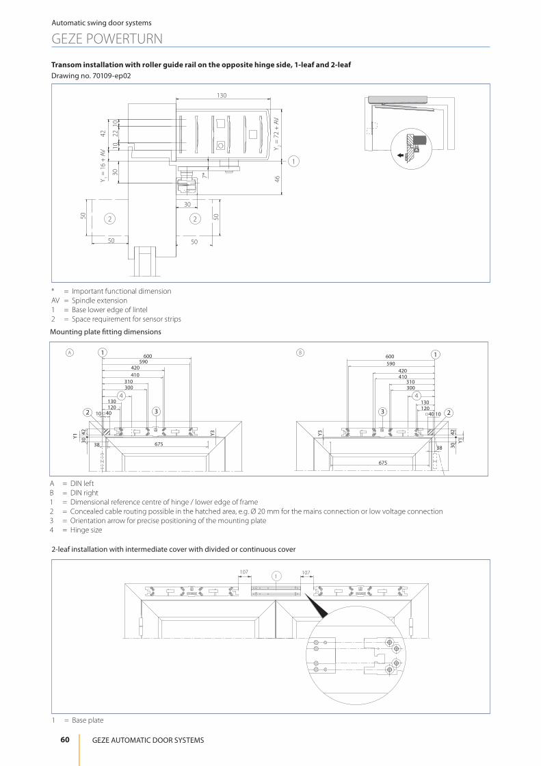
60
Automatic swing door systems
GEZE POWERTURN
GEZE AUTOMATIC DOOR SYSTEMS
Transom installation with roller guide rail on the opposite hinge side, 1-leaf and 2-leaf Drawing no. 70109-ep02
130
Y 2 = 7
2 +
AV
467*
42Y 1 =
16
+ A
V
1010
3022
50 50
50
30
50
2 2
1
* = Important functional dimensionAV = Spindle extension1 = Base lower edge of lintel2 = Space requirement for sensor strips
4 4
A B
A = DIN leftB = DIN right1 = Dimensional reference centre of hinge / lower edge of frame2 = Concealed cable routing possible in the hatched area, e.g. Ø 20 mm for the mains connection or low voltage connection3 = Orientation arrow for precise positioning of the mounting plate4 = Hinge size
Mounting plate fitting dimensions
107 1071
1 = Base plate
2-leaf installation with intermediate cover with divided or continuous cover

61
Automatic swing door systems
GEZE POWERTURN
Swing Door Systems
Door leaf installation with roller guide rail on the hinge side, 1-leaf and 2-leafDrawing no. 70109-ep03
* = Important functional dimensionAV = Spindle extension1 = Base upper edge of door2 = Space requirement for sensor strips
3 3
A B
A = DIN leftB = DIN right1 = Dimensional reference centre of hinge / upper edge of door2 = Orientation arrow for precise positioning of the mounting plate3 = Hinge size
Mounting plate fitting dimensions
13030
7*
46
1010
2242X 1 =
16
+ A
V
50 50
50 50
2 2
1
X 2=92
+AV
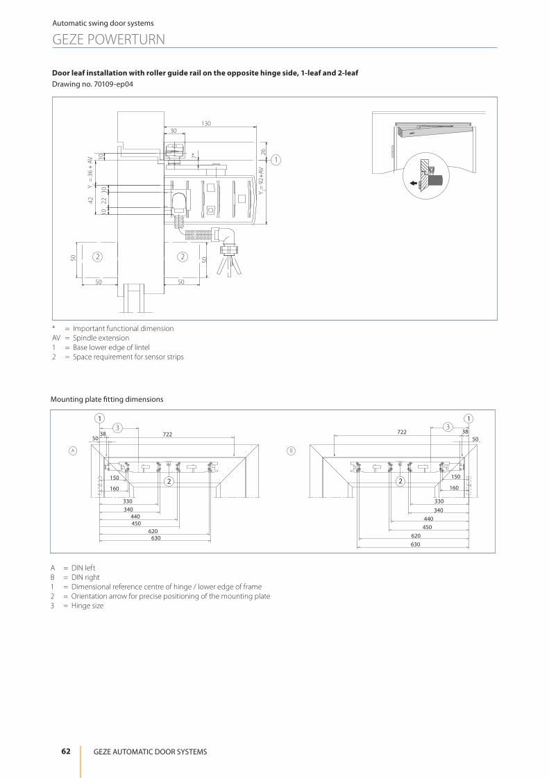
62
Automatic swing door systems
GEZE POWERTURN
GEZE AUTOMATIC DOOR SYSTEMS
Door leaf installation with roller guide rail on the opposite hinge side, 1-leaf and 2-leafDrawing no. 70109-ep04
* = Important functional dimensionAV = Spindle extension1 = Base lower edge of lintel2 = Space requirement for sensor strips
3 3
A B
A = DIN leftB = DIN right1 = Dimensional reference centre of hinge / lower edge of frame2 = Orientation arrow for precise positioning of the mounting plate3 = Hinge size
Mounting plate fitting dimensions
7*
13030
10
26
1010
2242Y 1 =
36
+ A
V
50 50
50 50
2 2
1
Y 2= 9
2+AV

63
Automatic swing door systems
GEZE POWERTURN
Swing Door Systems
Door leaf installation with link arm on the hinge side, 1-leaf and 2-leafDrawing no. 70109-ep06
* = Important functional dimensionAV = Spindle extension1 = Base upper edge of door2 = Space requirement for sensor strips
3 3
A B
A = DIN leftB = DIN right1 = Dimensional reference centre of hinge 2 = Orientation arrow for precise positioning of the mounting plate3 = Hinge size
Mounting plate fitting dimensions
X 2=92
+AV
50
X 1 = 1
6 +
AV
30
42
7*
43
1010
22
50
50 50
2
1
2

64
Automatic swing door systems
GEZE POWERTURN
GEZE AUTOMATIC DOOR SYSTEMS
Transom installation with link arm on the opposite hinge side, 1-leaf and 2-leafDrawing no. 70109-ep05
43
42Y 1 =
16
+ AV
Y 2 = 7
2 +
AV
1010
22LT
130
50 50
30* 8*
*
50 50
1
2 2
AV = 30
* = With sensor adapter 35.5 mm** = Important functional dimensionAV = Spindle extension
4 4
30*
30*
A B
* = With sensor adapter 35.5 mmA = DIN leftB = DIN right
Mounting plate fitting dimensions
107 1071
1 = Base plate
2-leaf installation with intermediate cover with divided or continuous cover
1 = Dimensional reference centre of hinge / upper edge of door2 = Concealed cable routing possible in the hatched area, e.g. Ø 20 mm for the mains connec-
tion or low voltage connection3 = Orientation arrow for precise positioning of the mounting plate4 = Hinge size
LT = Reveal depth1 = Base lower edge of lintel2 = Space requirement for sensor strips

65
Automatic swing door systems
GEZE POWERTURN
Swing Door Systems
Powerturn IS/TS: transom installation with guide rail on the hinge side, 2-leafDrawing no. 70109-ep21
22
10
(42)
1010
36
1526
67
92
70
36
130
(42)
31
19
9
36
10
70
92
2210
130
21
1 = Powerturn with roller guide rail and GC 338 sensor strip2 = TS 5000 L door closer with guide rail
Attachment of mounting plate (Powerturn) and base plate (TS 5000 L)
Maße Rollenschiene (Powerturn), GC 338 und Gleitschiene (TS 5000 L)
B
12.5K = B-1211107190
36
(42)
25
190
30
57
38497
422
0
0
776
745
600
590
420
410
310
300
130
120
(50)
2
1
2
1
K = Position of intermediate base plateB = Hinge clearance1 = Hinge size2 = Dimensional reference centre of hinge
2 2
1 3 3 1B-1180
190
38 675 120428.5
30** 30**
190 330 333
720 460
B = Hinge clearance** = Recommended dimensions for installation of GC 335 and GC 338 sensor strips1 = Hinge size2 = Dimensional reference centre of hinge3 = Lever length

66
Automatic swing door systems
GEZE POWERTURN
GEZE AUTOMATIC DOOR SYSTEMS
Powerturn IS/TS: transom installation with link arm on the opposite hinge side, 2-leafDrawing no. 70109-ep25
21
7270
8
36
46(4
2) 2210
10
30
15
83
130
10
(42)
102272
25.5 41
130
1 = Powerturn with link arm and GC 338 sensor strip2 = TS 4000 door closer with link arm
2
1
2
1
15154
36
(42)
190K = B-121112.5
190107
B
38 497
422
0 776
745
10600
590
420
410
310
300
130
120
50
K = Position of the intermediate base plateB = Hinge clearance1 = Hinge size2 = Dimensional reference centre of hinge
2 2
1 1
460 B-1180
190 190
44 268
30**30**
720
45222
B = Hinge clearance** = Recommended dimensions for installation of GC 335 und GC 338 sensor strips1 = Hinge size2 = Dimensional reference centre of hinge
Attachment of mounting plate (Powerturn) and base plate (TS 4000)
Dimensions link arm (Powerturn), GC 338 and link arm (TS 4000)

67
Automatic swing door systems
GEZE POWERTURN
Swing Door Systems
Legend for the cable diagrams
Cable1 = NYM-J 3 x 1.5 mm2
2 = J-Y(ST)Y 1 x 2 x 0.6 LG3 = J-Y(ST)Y 2 x 2 x 0.6 LG4 = J-Y(ST)Y 4 x 2 x 0.6 LG5 = LiYY 2 x 0.25 mm2
6 = LiYY 4 x 0.25 mm2
7 = Scope of supply sensor strip or LiYY 5 x 0.25 mm2
8 = Route empty pipe with pull-wire inner diameter 10 mm
Notes • Cable diagrams can also be prepared for specific building projects after receipt of order • Version of standard cable diagrams in accordance with GEZE specifications • Cable routing according to VDE0100/ IEE regulations • Allow the cable for the drive to project at least 1500 mm out of the wall
1) Door transmission cable (included in the scope of supply for sensor strip), cable routing through a hole in the door leaf is not permitted for fire control doors.2) Cable exit for door drive, see installation drawings for Powerturn3) Cable included in the scope of supply for the sensor4) Install in the direct vicinity of the door5) Mains connection box WxHxD min. 65 x 65 x 57 with PG-11 duct, on site6) Low-voltage connection box WxHxD min. 94 x 65 x 57 with PG-11 duct, on site7) E.g. door transmission cable, 8-wire, art. no. 0669228) Branch box, on site
AbbreviationsHS = Main switchNOT = Emergency-stop switchUT = Circuit breaker CLOSE DOOR (only with F variant)KB = Contact sensor authorisedPS = Programme switchST = Emergency stopKI = Contact sensor insideKA = Contact sensor outsideTOE = Door openerRM = Bar messageRS = Smoke switch (only with F variant)RSZ = Smoke switch control unit (only with F variant)TS = Door closerMK = Magnetic contact
3)3)KA
388
3221 11 1
KB
3
KI
3
ST
3
PS
D/D*
BA
C
HS NOT UT4)
III
II
I
IV
VV
I = Feeder 230 V / 50 HzII = 10 A fuseIII = Connected value 230 W, 1 A 1-, 2-leaf with manual fixed leaf; connected value 400 W, 1 A with 2-leafIV = And / OrV = Option
B+200
B/2
B
B/2
KI
KA
max. 100
max
. 300
5)
6)
Powerturn / Powerturn F

68
Automatic swing door systems
GEZE POWERTURN
GEZE AUTOMATIC DOOR SYSTEMS
1-leaf
RS 3 3RSRS 33RS
7
88
8)
C
A
B
D
C
A
B
D
3 3
6)
5)1RSZ
RMTOE
1
12
RSZ
2)
1)
8
RMTOE
2)
GC 338 GC 338
Powerturn / Powerturn F
Powerturn / Powerturn F
I II
2-leaf
8
D*83
2)2)2)
*
83
1
D
7
7
C
A
B
DC
A
B
D
6
1
6)
5)
6)
5)
RM
3
1
TOE
RSZ
RMTOE
RM
3
1
1TOE
2
RSZ
2)
1)
8
RMTOE
8)
8
8
7)
4
7
RS 3 3RSRS 3 3RS
6
GC 338 GC 338 GC 338 GC 338
III IV
III IV
Powerturn / Powerturn F
I II
Powerturn / Powerturn F Powerturn /
Powerturn FPowerturn / Powerturn F
Photo: GEZE GmbH
I = Transom installationII = Door leaf installationIII = Fixed leafIV = Active leaf

Accessories for swing door systems
Hood, mounting plate, link arm, roller guide rail with lever
HoodThe hood is available in an anodised or coloured finish. In the case of double-leaf versions, the hood can be ordered as a continuous variant or with intermediate hood.
Mounting plate for drives (option)A mounting plate may be necessary, depending on the installation situation. A mounting plate is generally recommended to make installation easier. A respective mounting plate is supplied according to the hood version.
Link armsare offered for different reveal depths
Roller guide rail with leverInstallation depends on the type of hinge action chosen.
Cover Mounting plate Link arm
Roller guide rail / guide rail with lever
69
Automatic swing door systems
ACCESSORIES
Swing Door Systems
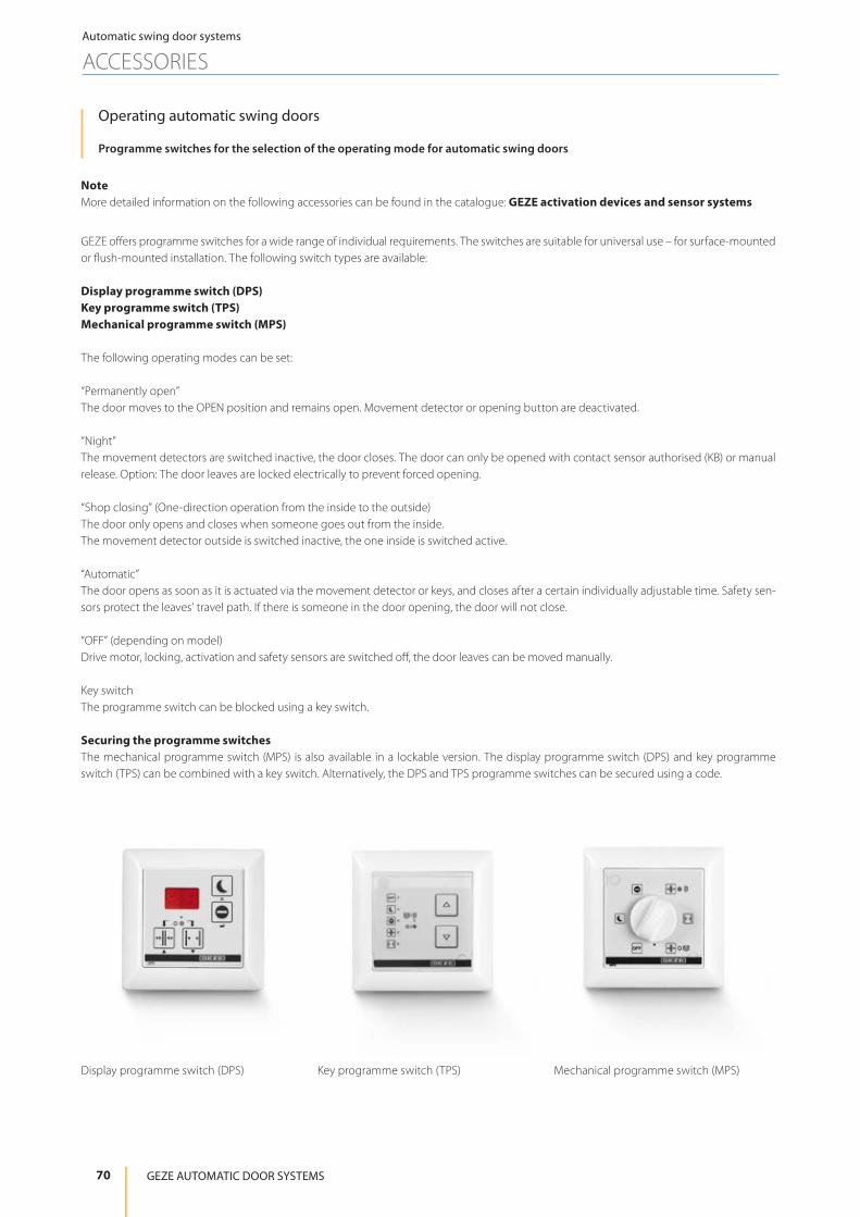
NoteMore detailed information on the following accessories can be found in the catalogue: GEZE activation devices and sensor systems
Operating automatic swing doors
Programme switches for the selection of the operating mode for automatic swing doors
GEZE offers programme switches for a wide range of individual requirements. The switches are suitable for universal use – for surface-mounted or flush-mounted installation. The following switch types are available:
Display programme switch (DPS)Key programme switch (TPS)Mechanical programme switch (MPS)
The following operating modes can be set:
“Permanently open”The door moves to the OPEN position and remains open. Movement detector or opening button are deactivated. “Night”The movement detectors are switched inactive, the door closes. The door can only be opened with contact sensor authorised (KB) or manual release. Option: The door leaves are locked electrically to prevent forced opening.
“Shop closing” (One-direction operation from the inside to the outside)The door only opens and closes when someone goes out from the inside. The movement detector outside is switched inactive, the one inside is switched active.
“Automatic”The door opens as soon as it is actuated via the movement detector or keys, and closes after a certain individually adjustable time. Safety sen-sors protect the leaves’ travel path. If there is someone in the door opening, the door will not close.
“OFF” (depending on model)Drive motor, locking, activation and safety sensors are switched off, the door leaves can be moved manually.
Key switchThe programme switch can be blocked using a key switch.
Securing the programme switchesThe mechanical programme switch (MPS) is also available in a lockable version. The display programme switch (DPS) and key programme switch (TPS) can be combined with a key switch. Alternatively, the DPS and TPS programme switches can be secured using a code.
Display programme switch (DPS) Key programme switch (TPS) Mechanical programme switch (MPS)
70
Automatic swing door systems
ACCESSORIES
GEZE AUTOMATIC DOOR SYSTEMS
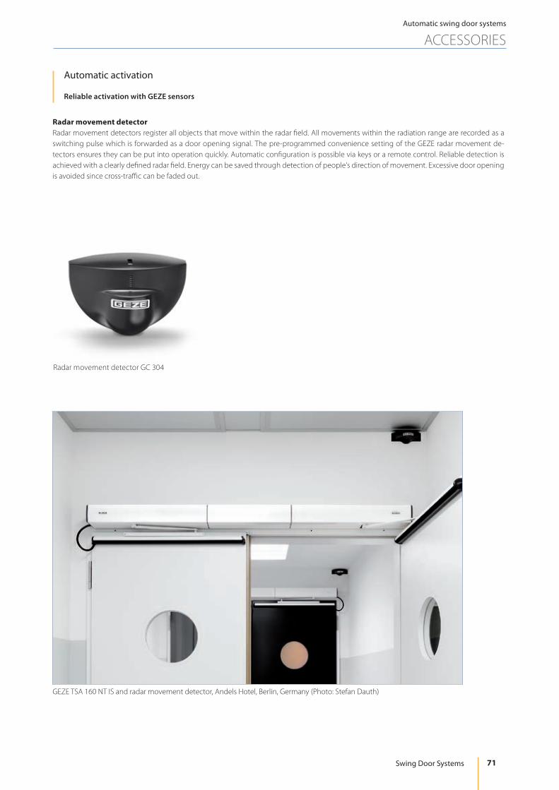
Automatic activation
Reliable activation with GEZE sensors
Radar movement detectorRadar movement detectors register all objects that move within the radar field. All movements within the radiation range are recorded as a switching pulse which is forwarded as a door opening signal. The pre-programmed convenience setting of the GEZE radar movement de-tectors ensures they can be put into operation quickly. Automatic configuration is possible via keys or a remote control. Reliable detection is achieved with a clearly defined radar field. Energy can be saved through detection of people’s direction of movement. Excessive door opening is avoided since cross-traffic can be faded out.
GEZE TSA 160 NT IS and radar movement detector, Andels Hotel, Berlin, Germany (Photo: Stefan Dauth)
Radar movement detector GC 304
71
Automatic swing door systems
ACCESSORIES
Swing Door Systems

Manual activation
Push buttonsGEZE push buttons for the wireless activation of system doors – reliable, convenient and safe at the push of a button.
Capacitive push buttonThe design-oriented and sturdy LED sensor button makes intuitive and straightforward operation possible. No great efforts are required for activation – touching the button slightly is sufficient. Suitable for use both indoors and outdoors, the LED sensor button can be recognised easily in the dark thanks to the blue LED lighting. In addition, the sensor has raised Braille lettering on it. A visual signal initiates activation through the push button. The push button is waterproof, impact-resistant and vandalism-proof. This makes it very well suited for outdoor use or installation in the floor.
Non-contact proximity switchOpen doors in a flash: With GEZE infrared sensors, internal doors without precise perception requirement can be actuated cleanly and comfor-tably. Active infrared sensors ensure hygienic access to toilet facilities, for example. The risks of infection are also minimised in hotel kitchens, hospitals and doctors’ surgeries. The impulse generator is installed at hand height and precisely detects people and objects – independently of their direction of movement – both in the direct vicinity of only 5 cm as well as 0.6 m away. The different scanning ranges can be optimally adapted to existing environmental conditions and the wishes of the user groups. The non-contact sensor system provides maximum operating convenience – people only need to approach them to trigger the automatic opening mechanism. The optimum system structure permits simple and time-saving installation in the flush-mounted box.
Radio activationGEZE radio transmitters are used for wireless activation of doors and windows as a multi-channel solution. For every additional channel, an additional electrical device or function can be switched at the push of a button. Thanks to the very small size of the radio modules, radio trans-mitters can easily be integrated in the drive or in a flush-mounted box. They can also be clipped directly into the elbow switched and mounted without wires on glass.
Push button LED sensor button Non-contact proximity switch GC 306
Radio activation Plastic elbow switch Stainless steel elbow switch IP65
72
Automatic swing door systems
ACCESSORIES
GEZE AUTOMATIC DOOR SYSTEMS

Electronic protection
Safety sensor strips Safety sensor strips are used to monitor and safeguard the pivoting area of automatic swing door leaves. They are installed on both sides of the door, directly on the leaf. This guarantees maximum protection both during opening and closing of the door.
GEZE safety sensors work with infrared light. Electromagnetic waves which are invisible to the human eye record people or objects within the area of detection. A receiver absorbs the reflected infrared beams and converts them into an electric signal which is transmitted to the control unit of the door drive. Door movement in the opening direction is stopped as soon as the sensor registers an obstacle. It is possible for the wall areas to be faded out by the safety sensors (teachable). In closing direction, the sensor actuates the drive of the closing door and opens it again.
GC 338 sensor strip The energy- and space-saving sensor strip GC 338 has a very large safety range and offers enhanced protection on the primary and secondary closing edges. In addition, the sensor has a wall blanking feature which makes it possible to guarantee maximum safety even with doors that open against walls. Safeguarding all GEZE swing door drives with door leaf widths of up to 1500 millimetres is achieved with only one sensor system. The GC 338 not only offers advantages for installation and commissioning – the complete door system is supplied via an interface. The sensor strip automatically adapts to its environment. This saves learning time and installation costs. The GEZE sensor strip GC 338 has the following features:
• Reliable function under all weather and floor conditions up to 3.5 m in accordance with DIN 18650 / EN 16005 • One sensor system safeguards door leaf widths of up to 1500 mm • Wall blanking: The sensor can detect a wall and blank this out automatically • Elegant roller guide rail can even be used with slim door profiles • Current consumption in operating mode: 200 mA • Quick and easy installation of the modules using the SNAP-IN mechanism, allowing modules to be positioned and fixed in the profile
without tools
GC 338 sensor strip
Frontal detection field Integrated wall blanking
73
Automatic swing door systems
ACCESSORIES
Swing Door Systems

To secure the door in accordance with DIN 1860 / EN 16005, the following modules are required additionally for each door side: • 1 transmitter module • 1 receiver module
Please find more details in the GC 338 operation manual.
Installation on the hinge side
1
Safety sensor „open“ mounted on the hinge side
1
Safety sensor „close“ mounted on the oppo-site hinge side
90 Lx
Ø101
Safety sensor drill hole distances hinge side
Installation on the opposite hinge side
1
Safety sensor „close“ mounted on the oppo-site hinge side
1
Safety sensor „open“ mounted on the hinge side
90Lx
Ø101
Safety sensor drill hole distances opposite hinge side
1 = optional power supply, concealed routing possible. Drill hole Ø 10 for concealed cable routing.Lx = Profile length 1100 mm : Lx = 489 mm; profile length 1500 mm : Lx = 699 mm
A B
S2S1 I E2E1
>120
20
25–30 mm 25–30 mm
S1S2 E2 E1
25–30 mmca. 100 mm 25–30 mm
> 120
A = Handle bar leftB = Handle bar right
Safety sensors on door leaf with vertical handle bars
74
Automatic swing door systems
ACCESSORIES
GEZE AUTOMATIC DOOR SYSTEMS

Sensor roller guide rail GC GR - the ideal combination of safety and designThe GC GR sensor roller roller guide rail is available for the complete range of Slimdrive EMD models as well as all the TSA 160 NT and Power-turn drive versions. The sensor and the roller roller guide rail can be put together in such a way that they look like a single compact and more integrated design. The features at a glance:
• Suitable for single and double-leaf swing door • Available for all TSA 160 NT, Slimdrive EMD and Powerturn variants with roller guide rail • Sensor and roller roller guide rail profile are available separately, facilitating retrofittings to existing systems • The rain cover is available as accessory
3
4
21
1 = Sensor roller guide rail2 = Sensor strip3 = End cap for sensor roller guide rail4 = End cap for sensor strip
Sensor roller guide rail GC GR
Adapter for sensor and link arm for slimdrive EMD and TSA 160 NT - Integration of link arm and sensor strips on one levelExactly similar as in case of the sensor roller guide rail GC GR, the newly introduced adapter for link arm and sensor enables an optimal instal-lation on doors with slim frames. The link arm program of the Slimdrive EMD and TSA 160 NT drives was re-worked, so that the adapter can be combined with new link arms. Advantages:
• Better integration of link arm and sensor strip GC 338, GC 335 or GC 338 into the door design • Simple installation, in particular in case of slim door frames • With the new link arms a maximum reveal depth of 400 mm can now be bridged
Adapter for sensor and link arms for Slimdrive EMD and TSA 160 NT
75
Automatic swing door systems
ACCESSORIES
Swing Door Systems

EMD and GC GR (GC 338) transom installation with roller guide rail on the hinge sideDrawing no. 70106-ep35
EMD and GC GR (GC 338) transom installation with roller guide rail on the opposite hinge sideDrawing no. 70106-ep35
EMD
6840
34
70
50
(51.
2)(4
3.4)
75
EMD
40
50
15
68
95
(43.
4)(5
1.2)
50
70
76
Automatic swing door systems
ACCESSORIES
GEZE AUTOMATIC DOOR SYSTEMS

TSA 160 NT and GC GR (GC 338) transom insatallation with roller guide rail on the hinge sideDrawing no. 70106-ep35
GC GR (GC 338) 1200 mm with roller guide rail, single leafDrawing no. 70106-ep35Note: For double-leaf doors mirror and add this view.
BA
37.5
15
( 28.6
)
15~50
30 30LL/2
~50 ~50
1717L1 /2
3030
L1
A = Hinge sideB = Opposite hinge sideL = Length
TSA160NT
684055
21
7012
0
(42)
(54)
50
77
Automatic swing door systems
ACCESSORIES
Swing Door Systems

78
Automatic swing door systems
ACCESSORIES
GEZE AUTOMATIC DOOR SYSTEMS
Photo: GEZE GmbH
GEZE laser scanner GC 342Laser scanner for the protection of automatic swing doors in compliance with DIN 18650/EN 16005
The compact and space-saving GEZE sensor GC 342 serves to protect automatic swing doors in compliance with DIN 18650/EN 16005. The sensor is preferred for use with difficult floor conditions (e.g. floor mats, metal runners, dark and absorbent floors). A large field of detection ensures protection of the main and secondary closing edges, with a wide recording field across the entire width of the door. The sensor also has wall blanking, guaranteeing maximum security even with doors that run against walls. The GC 342 automatically learns its environment. With just one sensor system, the safety of all GEZE swing doors drives up to door leaf widths of 1600 mm can be achieved.
Thanks to the integrated wall blanking, the sensor learns its permanently installed environment – walls, radiators, windowsills. The parameter adjustment of the wall blanking in the drive can be omitted. The installation on the upper edge of the door near the hinge is cleverly solved and therefore is quick and easy to achieve. The door leaf width to be locked is learned using hand movements. Settings such as the position of the master module on the hinge side/opposite hinge side, immunity, background monitoring and monitoring of the secondary closing edge can be handled easily using dip switches.

Service Tools
GEZEconnectsBluetooth is an internationally standardised short-distance radio signal with a range of up to ten metres. The software GEZEconnects makes wireless connection via Bluetooth possible between a computer and the automatic door systems from GEZE. All door system settings can be carried out via an intuitive graphic interface, stored, sent by e-mail and transferred to a word processing programme as a protocol. Diagnosis functions show the most important function parameters of the door system in real time, so that problems are recognised at a glance and can be eliminated. All the pre-settings can be taken over very easily for further door systems. The convenient documentation of initial operation, servicing and diagnosis protocols as well as all statistical data can be downloaded at any time. Password protection to freeze operating para-meters and servicing data guarantees there will be no unauthorised modifications made.
Service terminal ST 220Mobile, handy and straightforward – that is the parameter setting for the automatic GEZE door systems using the service terminal ST 220. Communication and data exchange between the service terminal and the door drive is via an integrated RS485 interface. The large illuminated display is easy to operate thanks to the plain text display. The service terminal is equipped with a readout function for servicing and diagnosis work. Power is supplied via the door system. Password protection to freeze operating parameters and servicing data guarantees there will be no unauthorised modifications made.
A service adapter for the ST 220 which is available separately can be laterally inserted from the outside into the drive, allowing operating para-meters and service data to be read out and parameters to be set without the drive cover having to be removed.
Notes• GEZE service tools are available for the Slimdrive EMD, TSA 160 NT and Powerturn range of drives.• Parameters of GEZE drives may only be changed by technicians trained in accordance with DIN 18650/EN 16005 and authorized by the
manufacturer (GEZE).
B E W E G U N G M I T S Y S T E M
GEZEconnects I SOFTW AREzur kabellosen Verbindung von GEZE Automatischen Türsystemen und PCs über Bluetooth
GEZ
Eco
nn
ects
I S
OFT
WA
RE
GEZE GmbHReinhold-Vöster-Str. 21-2971229 Leonberg Germany
Telefon: +49 (0)7152-203-0Telefax: +49 (0)7152-203-310
www.geze.com
Systemvoraussetzungen:
PC mit Windows XPIntel oder 100% kompatiblen Prozessor500 MB RAM1,5 GHzCD LaufwerkBluetooth Schnittstelle150 MB freier Speicherplatz
TÜRTECHNIK
AUTOMATISCHE TÜRSYSTEME
RWA UND LÜFTUNGSTECHNIK
SICHERHEITSTECHNIK
GLASSYSTEME Id.Nr. 134995 · Version 090518 · Änderungen vorbehalten
GEZEconnects I SOFTW AREzur kabellosen Verbindung von GEZE Automatischen Türsystemen und PCs über Bluetooth
B E W E G U N G M I T S Y S T E M
GEZEconnects Service terminal ST 220
79
Automatic swing door systems
ACCESSORIES
Swing Door Systems
Service adapter for ST 220
Bluetooth service adapter for ST 220
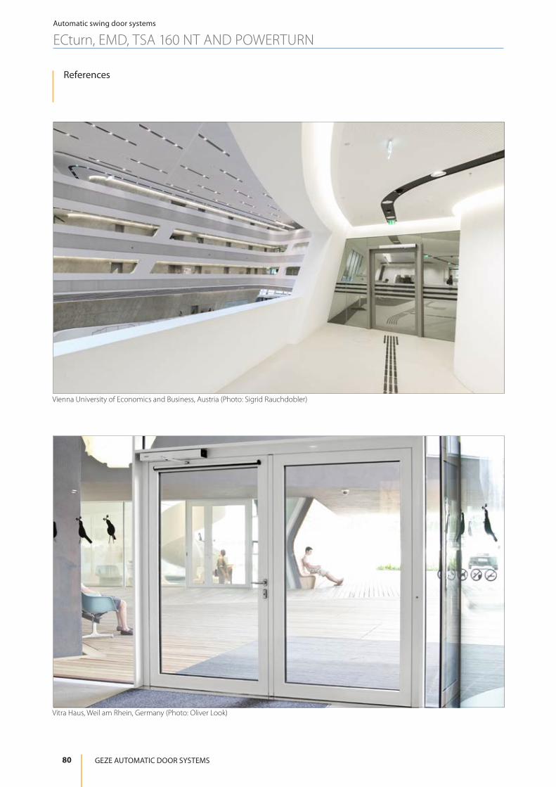
80
Automatic swing door systems
ECturn, EMD, TSA 160 NT AND POWERTURN
GEZE AUTOMATIC DOOR SYSTEMS
References
Vienna University of Economics and Business, Austria (Photo: Sigrid Rauchdobler)
Vitra Haus, Weil am Rhein, Germany (Photo: Oliver Look)

81
Automatic swing door systems
ECturn, EMD, TSA 160 NT AND POWERTURN
Swing Door Systems
Danish Association for Disabled, Taastrup, Denmark (Photo: Morten Bak)
Municipal Library, Stuttgart, Germany (Photo: Lazaros Filoglou)

82 GEZE AUTOMATIC DOOR SYSTEMS
Innovative system solutions
POTENTIAL APPLICATIONS OF GEZE PRODUCTS
01
04
06
07
20 07
10
08
11
13
11
22
17
06
02
14
You will find more product information in the relevant brochures, see ID numbers.
Door technology
01 Overhead door closersID 091593, ID 091594
02 Hold-open systemsID 091593, ID 091594
03 Integrated door closers ID 091609
04 Floor springs and all-glass fittingsID 091607
05 Sliding fitting systems and linear guidesID 123605, ID 000586
Automatic door systems
06 Swing doorsID 144785
07 Sliding, telescopic and folding doorsID 143639
08 Curved sliding doorsID 135772
09 Revolving doorsID 132050
10 Activation devices and sensorsID 142655
Smoke and heat extraction and window technology
11 Fanlight opening systemsID 127787
12 Electric opening and locking systemsID 127785, ID 127789
13 Electrical spindle and linear drivesID 127785, ID 127789
14 Electric chain drivesID 127785, ID 127789
15 Smoke and heat extraction systemsID 127785, ID 139075
Safety technology
16 Emergency exit systemsID 132408
17 Access control systemsID 132158
18 Panic locksID 132848
19 Electric strikesID 148666
20 Building management systemID 132408
Glass systems
21 Manual sliding wall systems (MSW)ID 104377
22 Integrated all-glass systems (IGG)ID 104366
04

83Swing Door Systems
Innovative system solutions
POTENTIAL APPLICATIONS OF GEZE PRODUCTS
21
18
03
05
09
16
19
12
15
21
15 17
Door technology
The functionality, superior performance and reliability of GEZE door closers are impressive. A common design across the range, the ability to use them on all common door leaf widths and weights, and the fact that they can be individu-ally adjusted makes their selection simple. They are con-tinually being improved and enhanced with up-to-date fea-tures. For example, the requirements of fire protection and accessibility are fulfilled with a door closer system.
Automatic door systems
GEZE automatic door systems open up a huge variety of options in door design. The latest, innovative high-per-formance drive technology, safety, ease of accessibility and first class universal drive design set them apart. GEZE offers complete solutions for individual requirements. A dedicated division is responsible for the development and construction of individual special designs.
Smoke and heat extraction and window technology
GEZE smoke and heat extraction systems and ventilation technology provide complete systems solutions combin-ing the many requirements of different types of windows. We supply a full range from energy efficient drive systems to natural ventilation and complete solutions for supplying and extracting air, also as certified SHEVs.
Safety technology
GEZE safety technology sets the standards where preven-tative fire protection, access control and anti-theft security in emergency exits are concerned. For each of these objec-tives GEZE offers tailored solutions, which combine the in-dividual safety requirements in one intelligent system and close doors and windows in case of danger in a coordinated manner.
Building systems
In GEZE’s Building Management System GEZE door, win-dow and safety products can be integrated in to the se-curity and control systems of the building. A central con-trol and visualisation system monitors various automation components in the building and offers security through many different networking capabilities.
Glass systems
GEZE glass systems stand for open and transparent interior design. They can either blend discreetly into the architec-ture of the building or stand out as an accentuated feature. GEZE offers a wide variety of technologies for functional, reliable and aesthetic sliding wall or sliding door systems providing security with lots of design scope.
G E Z E AU TO M AT I C D O O R S YS T E M S
G E Z E R E P R E S E N TAT I V E
Id.No. 144785 · Vers. EN 1703 · Subject to modification
GEZE GmbHP.O. Box 136371226 LeonbergGermany
GEZE GmbHReinhold-Vöster-Straße 21-2971229 LeonbergGermanyTelefon +49 7152 203 0Telefax +49 7152 203 310www.geze.com
GermanyGEZE GmbHNiederlassung Süd-WestBreitwiesenstraße 871229 LeonbergTel. +49 7152 203 594Fax +49 7152 203 [email protected]
GEZE GmbHNiederlassung Süd-OstParkring 1785748 Garching bei MünchenTel. +49 7152 203 6440Fax +49 7152 203 [email protected]
GEZE GmbHNiederlassung OstAlbert-Einstein-Ring 514532 Kleinmachnow bei BerlinTel. +49 7152 203 6840Fax +49 7152 203 [email protected]
GEZE GmbHNiederlassung Mitte/LuxemburgAdenauerallee 261440 Oberursel (b. Frankfurt)Tel. +49 7152 203 6888Fax +49 7152 203 [email protected]
GEZE GmbHNiederlassung WestHeltorfer Straße 1240472 DüsseldorfTel. +49 7152 203 6770Fax +49 7152 203 [email protected]
GEZE GmbHNiederlassung NordAlbert-Schweitzer-Ring 24-26 (3. OG)22045 HamburgTel. +49 7152 203 6602Fax +49 7152 203 [email protected]
GEZE Service GmbH Niederlassung Süd-WestReinhold-Vöster-Straße 2571229 LeonbergTel. +49 1802 923392Fax +49 7152 9233 [email protected]
GEZE Service GmbH Niederlassung SüdParkring 1785748 Garching bei MünchenTel. +49 1802 923392Fax +49 7152 9233 [email protected]
GEZE Service GmbH Niederlassung MitteOberurseler Str. 6961440 OberurselTel. +49 1802 923392Fax +49 7152 9233 [email protected]
GEZE Service GmbH Niederlassung WestHeltorfer Straße 1240472 DüsseldorfTel. +49 1802 923392Fax +49 7152 9233 [email protected]
GEZE Service GmbH Niederlassung OstAlbert-Einstein-Ring 514532 Kleinmachnow bei BerlinTel. +49 1802 923392Fax +49 7152 9233 [email protected]
GEZE Service GmbHNiederlassung NordAlbert-Schweitzer-Ring 24-26 (3. OG)22045 HamburgTel. +49 1802 923392Fax +49 7152 9233 [email protected]
AustriaGEZE AustriaWiener Bundesstrasse 85A-5300 HallwangTel: +43 6225 87180Fax: +43 6225 87180 [email protected]
Baltic States – Lithuania / Latvia / EstoniaTel. +371 678960 [email protected]
BeneluxGEZE Benelux B.V.Industrieterrein KapelbeemdSteenoven 36 5626 DK EindhovenTel. +31 4026290 80Fax +31 4026290 [email protected]
BulgariaGEZE Bulgaria - Trade Representative OfficeNickolay Haitov 34 str., fl. 11172 SofiaTel. +359 247043 73 Fax +359 247062 [email protected]
ItalyGEZE Italia S.r.lSede di VimercateVia Fiorbellina 20 20871 Vimercate (MB) Tel. +39 0399530401 Fax+39 039 9530459/[email protected]
Sede di RomaVia Lucrezia Romana, 9100178 RomaTel. +39 039 9530401Fax +39 039 [email protected]
PolandGEZE Polska Sp. z o.o.ul. Marywilska 24 03-228 WarszawaTel. +48 224 404 440Fax +48 224 404 [email protected]
RomaniaGEZE Romania S.R.L.IRIDE Business Park,Str. Dimitrie Pompeiu nr. 9-9a,Building 10, Level 2, Sector 2,020335 BucharestTel.: +40 212507 750Fax: +40 316201 [email protected]
RussiaOOO GEZE RUSGamsonovskiy Per. 2115191 MoscowTel. +7 495 93306 59Fax +7 495 93306 [email protected]
Scandinavia – SwedenGEZE Scandinavia ABMallslingan 10Box 706018711 Täby, SwedenTel. +46 87323 400Fax +46 87323 [email protected]
Scandinavia – NorwayGEZE Scandinavia AB avd. NorgeIndustriveien 34 B2073 DalTel. +47 63957 200Fax +47 63957 [email protected]
Scandinavia – DenmarkGEZE DanmarkBranch office of GEZE Scandinavia AB Mårkærvej 13 J-K2630 TaastrupTel. +45 463233 24Fax +45 463233 [email protected]
SingaporeGEZE (Asia Pacific) Pte. Ltd.21 Bukit Batok Crescent #23-75 Wcega TowerSingapore 658065Tel: +65 6846 1338Fax: +65 6846 [email protected]
South AfricaGeze South Africa (Pty) Ltd.GEZE, Building 3, 1019 Morkels CloseMidrand 1685Tel: + 87 94337 88Fax: + 86 66137 [email protected]
SwitzerlandGEZE Schweiz AGZelglimatte 1A6260 ReidenTel. +41 62 28554 00Fax +41 62 28554 [email protected]
TurkeyGEZE Kapı ve Pencere SistemleriSan. ve Tic. Ltd. Sti.İstanbul Anadolu Yakası OrganızeSanayı BolgesiGazi Bulvari Caddesi 8.Sokak No:8 Tuzla-IstanbulTel. + 90 216 45543 15Fax + 90 216 45582 [email protected]
UkraineLLC GEZE Ukraineul. Viskoznaya, 17, Building 93-B, Office 1202660 KievTel./Fax +38 [email protected]
United Arab Emirates/GCCGEZE Middle EastP.O. Box 17903Jebel Ali Free Zone DubaiTel. +971 48833 112Fax +971 48833 [email protected]
United KingdomGEZE UK Ltd.Blenheim WayFradley ParkLichfieldStaffordshire WS13 8SYTel. +44 15434430 00Fax +44 15434430 [email protected]
ChinaGEZE Industries (Tianjin) Co., Ltd.Shuangchenzhong RoadBeichen Economic DevelopmentArea (BEDA)Tianjin 300400, P.R. ChinaTel. +86 22 26973995Fax +86 22 [email protected]
GEZE Industries (Tianjin) Co., Ltd.Branch Office ShanghaiJia Little Exhibition CenterRoom C 2-102Shenzhuan Rd. 6000201619 Shanghai, P.R. ChinaTel. +86 21 52340960Fax +86 21 [email protected]
GEZE Industries (Tianjin) Co., Ltd.Branch Office GuangzhouRoom 17 C 3Everbright Bank Building, No.689Tian He Bei Road510630 Guangzhou, P.R. ChinaTel. +86 20 38731842Fax +86 20 [email protected]
GEZE Industries (Tianjin) Co., LtdBranch Office BeijingRoom 04-05, 7th Floor Red Sandalwood Plaza No. 27 Jianguo Road Chaoyang District 100024 Beijing, P.R.China Tel. +86 10 85756009Fax +86 10 [email protected]
FranceGEZE France S.A.R.L.ZAC de l’Orme RondRN 1977170 ServonTel. +33 1 606260 70Fax +33 1 606260 [email protected]
HungaryGEZE Hungary Kft.Hungary-2051 BiatorbágyVendel ParkHuber u. 1.Tel. +36 23532 735Fax +36 23532 [email protected]
IberiaGEZE Iberia S.R.L.C/ Andorra 2408830 Sant Boi de Llobregat (Barcelona)Tel. +34 902194 036Fax +34 902194 [email protected]
IndiaGEZE India Private Ltd.MF 2 & 3, Guindy Industrial EstateEkkattuthangalChennai 600 097TamilnaduTel. +91 44 406169 00Fax +91 44 406169 [email protected]