Embed Size (px)
Citation preview
GETTING STARTED GUIDE
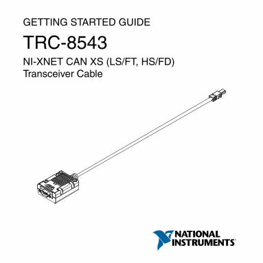
TRC-8543NI-XNET CAN XS (LS/FT, HS/FD)Transceiver Cable
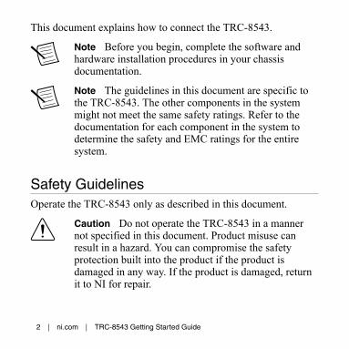
This document explains how to connect the TRC-8543.
Note Before you begin, complete the software andhardware installation procedures in your chassisdocumentation.
Note The guidelines in this document are specific tothe TRC-8543. The other components in the systemmight not meet the same safety ratings. Refer to thedocumentation for each component in the system todetermine the safety and EMC ratings for the entiresystem.
Safety GuidelinesOperate the TRC-8543 only as described in this document.
Caution Do not operate the TRC-8543 in a mannernot specified in this document. Product misuse canresult in a hazard. You can compromise the safetyprotection built into the product if the product isdamaged in any way. If the product is damaged, returnit to NI for repair.
2 | ni.com | TRC-8543 Getting Started Guide

Safety Guidelines for Hazardous LocationsThe TRC-8543 is suitable for use in Class I, Division 2, GroupsA, B, C, D, T4 hazardous locations; Class I, Zone 2, AEx nA IICT4 and Ex nA IIC T4 hazardous locations; and nonhazardouslocations only. Follow these guidelines if you are installing theTRC-8543 in a potentially explosive environment. Not followingthese guidelines may result in serious injury or death.
Caution Do not disconnect bus-side connector unlesspower has been switched off or the area is known to benonhazardous.
Caution Do not unplug the TRC-8543 unless powerhas been switched off or the area is known to benonhazardous.
Caution Substitution of components may impairsuitability for Class I, Division 2.
Caution For Division 2 and Zone 2 applications,install the system in an enclosure rated to at least IP54as defined by IEC/EN 60079-15.
TRC-8543 Getting Started Guide | © National Instruments | 3

Caution For Zone 2 applications, install a protectiondevice between the CAN bus and the TRC-8543 CANpins. The device must prevent the CAN Port-to-COMvoltage from exceeding 55 V if there is a transientovervoltage condition.
Special Conditions for Hazardous Locations Use inEurope and InternationallyThe TRC-8543 has been evaluated as Ex nA IIC T4 Gcequipment under DEMKO 12 ATEX 1202658X and is IECExUL 14.0089X certified. Each TRC-8543 is marked II 3G andis suitable for use in Zone 2 hazardous locations, in ambienttemperatures of -40 °C ≤ Ta ≤ 70 °C.
Caution You must make sure that transientdisturbances do not exceed 140% of the rated voltage.
Caution The system shall only be used in an area ofnot more than Pollution Degree 2, as defined inIEC/EN 60664-1.
Caution The system shall be mounted in anATEX/IECEx-certified enclosure with a minimum
4 | ni.com | TRC-8543 Getting Started Guide

ingress protection rating of at least IP54 as defined inIEC/EN 60079-15.
Caution The enclosure must have a door or coveraccessible only by the use of a tool.
Electromagnetic Compatibility GuidelinesThis product was tested and complies with the regulatoryrequirements and limits for electromagnetic compatibility (EMC)stated in the product specifications. These requirements andlimits provide reasonable protection against harmful interferencewhen the product is operated in the intended operationalelectromagnetic environment.
This product is intended for use in industrial locations. However,harmful interference may occur in some installations, when theproduct is connected to a peripheral device or test object, or if theproduct is used in residential or commercial areas. To minimizeinterference with radio and television reception and preventunacceptable performance degradation, install and use thisproduct in strict accordance with the instructions in the productdocumentation.
TRC-8543 Getting Started Guide | © National Instruments | 5

Furthermore, any changes or modifications to the product notexpressly approved by National Instruments could void yourauthority to operate it under your local regulatory rules.
Caution To ensure the specified EMC performance,operate this product only with shielded cables andaccessories. Do not use unshielded cables oraccessories unless they are installed in a shieldedenclosure with properly designed and shielded input/output ports and connected to the product using ashielded cable. If unshielded cables or accessories arenot properly installed and shielded, the EMCspecifications for the product are no longer guaranteed.
Mounting the TRC-8543Caution The TRC-8543 is a thermally active devicethat dissipates heat. Refer to the user manual of the hostthis device directly connects to for specific informationregarding thermal management. Not followingmounting requirements may affect the system ambient
6 | ni.com | TRC-8543 Getting Started Guide

temperature and/or the measurement accuracy ofmodules in the system.
Caution To meet thermal management requirements,do not zip tie more than six cables in a bundle, andallow for air flow around the bundle. If used with acRIO or cDAQ chassis, mount all cables at least152 mm (6.0 in.) from the chassis and do not mountmore than six cables directly beneath the chassis.
You can route and strain relieve the TRC-8543 similarly toordinary cables. You also can panel mount it using its removablejackscrews, zip tie, or screw mount it. The screw mounting holessupport #6 and M3 screws spaced 35.56 mm (1.400 in.) center-to-center, with minimum length of 23 mm (7/8 in.). The TRC-8543supports zip ties up to 5.33 mm (0.210 in.) wide.
The following figure shows jackscrews, zip tie mounting slots,and screw mounting holes on the TRC-8543.
TRC-8543 Getting Started Guide | © National Instruments | 7
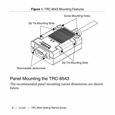
Figure 1. TRC-8543 Mounting Features
Screw Mounting Holes
Zip Tie Mounting Slots
Zip Tie Mounting Slots
Removeable Jackscrews
Panel Mounting the TRC-8543The recommended panel mounting cutout dimensions are shownbelow.
8 | ni.com | TRC-8543 Getting Started Guide

Figure 2. Recommended Cutout Dimensions
7.16
mm
(0.2
82 in
.)
0.00
mm
(0.0
00 in
.)
17.8
5 m
m(0
.703
in.)
18.4
2 m
m(0
.725
in.)
6.58
mm
(0.2
59 in
.)
24.9
9 m
m(0
.984
in.)
0.00 mm(0.000 in.) 1.65 mm
(0.065 in.)
1.63 mm(0.064 in.)
4X R 3.81 mm(0.150 in.)2X Ø 3.26 mm
(0.129 in.)
The jackscrews included with the TRC-8543 work with panelthicknesses up to 2.21 mm (0.087 in.).
Caution Tighten the jackscrews to a maximum torqueof 0.56 N · m (5.0 lb · in.).
If your panel is thicker than 2.21 mm (0.087 in.), you can mill outa recessed pocket for the TRC-8543. The following figure showsthe recommended pocket dimensions and cutout position.
TRC-8543 Getting Started Guide | © National Instruments | 9
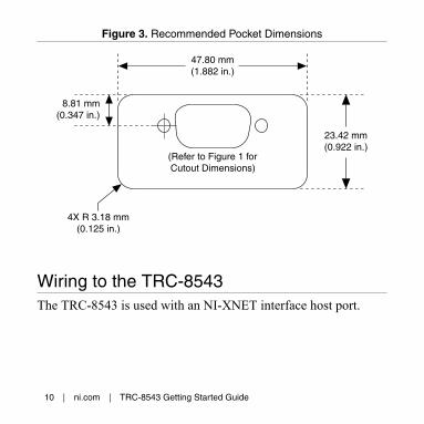
Figure 3. Recommended Pocket Dimensions
47.80 mm (1.882 in.)
23.42 mm(0.922 in.)
4X R 3.18 mm(0.125 in.)
8.81 mm(0.347 in.)
(Refer to Figure 1 forCutout Dimensions)
Wiring to the TRC-8543The TRC-8543 is used with an NI-XNET interface host port.
10 | ni.com | TRC-8543 Getting Started Guide

Figure 4. TRC-8543 Connections
To CAN Bus
To Host Port
The TRC-8543 has one 9-pin male D-Sub connector thatprovides connections to a CAN bus. The TRC-8543 has pins forCAN_H and CAN_L, to which you connect the CAN bus signals.Connect these signals using twisted-pair cable.
The port has two common pins (COM) that are internallyconnected to the TRC-8543 isolated reference and serve as thereference ground for CAN_H and CAN_L. You can connect theCAN bus reference ground (sometimes referred to as CAN_V-) toone or both COM pins.
The D-Sub connector shell connects through the TRC-8543shielding to the connector on the host port end. The shieldingdoes not electrically connect to the COM signals.
TRC-8543 Getting Started Guide | © National Instruments | 11

Caution When tightening the D-Sub connectorjackscrews, do not exceed the maximum jackscrewtorque of 0.56 N · m (5.0 lb · in.).
The TRC-8543 receives power from the NI-XNET host port, butalso requires an external power supply of +9 V to +30 V tooperate in Low-Speed/Fault-Tolerant mode. Supply power fromthe CAN bus to the VSUP pin.
Note Power on VSUP is required for Low-Speed/Fault-Tolerant CAN operation, but is not required for High-Speed CAN operation.
The TRC-8543 features software-selectable bus termination forboth CAN High-Speed/Flexible Data-Rate and Low-Speed/Fault-Tolerant transceivers. For High-Speed/Flexible Data-Rate mode,you can enable 115 Ω of termination resistance between CAN_Hand CAN_L through an API call. For Low-Speed/Fault-Tolerantmode, you can select either 1.11 kΩ or 4.99 kΩ of terminationresistance for RTH and RTL through an API call (refer to theTermination Resistors section for more information). If youchoose to use external termination, Table 4 lists recommendedtermination resistor values.
The following table lists the TRC-8543 pinout.
12 | ni.com | TRC-8543 Getting Started Guide

Table 1. Pin Assignments for the TRC-8543
Connector Pin Signal Name
6789
12345
1 No Connection (NC)
2 CAN_L
3 COM
4 NC
5 NC
6 COM
7 CAN_H
8 NC
9 VSUP
CAN Bus Topology and TerminationA CAN bus consists of two or more CAN nodes cabled together.The CAN_H and CAN_L pins of each node are connected to the
TRC-8543 Getting Started Guide | © National Instruments | 13

main CAN bus cable through a short connection known as a“stub.” The pair of signal wires, CAN_H and CAN_L, constitutesa transmission line. If the transmission line is not terminated,each signal change on the bus causes reflections that may causecommunication errors.
High-Speed/Flexible Data-Rate CANBecause the CAN bus is bidirectional, both ends of the cablemust be terminated. However, this requirement does not meanthat every node on the bus should have a termination resistor;only the two nodes at the far end of the cable should havetermination resistors.
The following figure shows a simplified diagram of a CAN buswith multiple CAN nodes and proper termination resistor (Rt)locations.
14 | ni.com | TRC-8543 Getting Started Guide
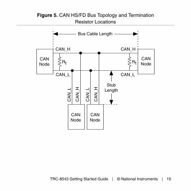
Figure 5. CAN HS/FD Bus Topology and TerminationResistor Locations
CANNode
CANNode
CANNode
Rt Rt
CANNode
CAN_H
CAN_L
CAN_H
CAN_L
CA
N_H
CA
N_L
CA
N_H
CA
N_L
Bus Cable Length
StubLength
TRC-8543 Getting Started Guide | © National Instruments | 15
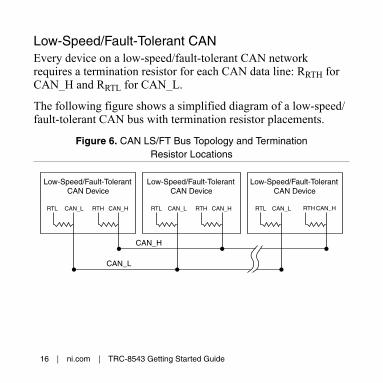
Low-Speed/Fault-Tolerant CANEvery device on a low-speed/fault-tolerant CAN networkrequires a termination resistor for each CAN data line: RRTH forCAN_H and RRTL for CAN_L.
The following figure shows a simplified diagram of a low-speed/fault-tolerant CAN bus with termination resistor placements.
Figure 6. CAN LS/FT Bus Topology and TerminationResistor Locations
RTL CAN_L RTH CAN_H RTL RTLCAN_L RTH CAN_H CAN_L RTH CAN_H
CAN_H
CAN_L
Low-Speed/Fault-TolerantCAN Device
Low-Speed/Fault-TolerantCAN Device
Low-Speed/Fault-TolerantCAN Device
16 | ni.com | TRC-8543 Getting Started Guide

Connecting a CAN Bus to the TRC-8543
High-Speed/Flexible Data-Rate CANYou can connect the TRC-8543 port to any location on a CANbus. The following figure shows one example of connecting theTRC-8543 directly to one CAN node.
Figure 7. Connecting the TRC-8543 to a CAN Device
TRC-8543
CA
N D
evic
e
RtShielded CAN Cable
CAN_H
CAN_L
COM
Rt
CAN_H
CAN_L
COM
Low-Speed/Fault-Tolerant CANYou can connect the TRC-8543 to any location on a Low-Speed/Fault-Tolerant CAN bus. The following figure shows oneexample of connecting the TRC-8543 directly to one CAN node.
TRC-8543 Getting Started Guide | © National Instruments | 17
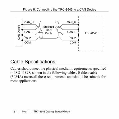
Figure 8. Connecting the TRC-8543 to a CAN Device
TRC-8543
CA
N D
evic
e ShieldedCAN Cable
CAN_H
CAN_L
VSUP
COM
CAN_H
CAN_L
VSUP
COM
Cable SpecificationsCables should meet the physical medium requirements specifiedin ISO 11898, shown in the following tables. Belden cable(3084A) meets all these requirements and should be suitable formost applications.
18 | ni.com | TRC-8543 Getting Started Guide
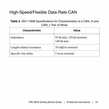
High-Speed/Flexible Data-Rate CAN
Table 2. ISO 11898 Specifications for Characteristics of a CAN_H andCAN_L Pair of Wires
Characteristic Value
Impedance 95 Ω min, 120 Ω nominal,140 Ω max
Length-related resistance 70 mΩ/m nominal
Specific line delay 5 ns/m nominal
TRC-8543 Getting Started Guide | © National Instruments | 19
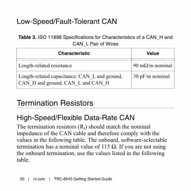
Low-Speed/Fault-Tolerant CAN
Table 3. ISO 11898 Specifications for Characteristics of a CAN_H andCAN_L Pair of Wires
Characteristic Value
Length-related resistance 90 mΩ/m nominal
Length-related capacitance: CAN_L and ground,CAN_H and ground, CAN_L and CAN_H
30 pF/m nominal
Termination Resistors
High-Speed/Flexible Data-Rate CANThe termination resistors (Rt) should match the nominalimpedance of the CAN cable and therefore comply with thevalues in the following table. The onboard, software-selectabletermination has a nominal value of 115 Ω. If you are not usingthe onboard termination, use the values listed in the followingtable.
20 | ni.com | TRC-8543 Getting Started Guide
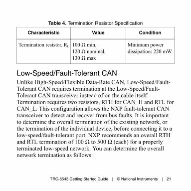
Table 4. Termination Resistor Specification
Characteristic Value Condition
Termination resistor, Rt 100 Ω min,120 Ω nominal,130 Ω max
Minimum powerdissipation: 220 mW
Low-Speed/Fault-Tolerant CANUnlike High-Speed/Flexible Data-Rate CAN, Low-Speed/Fault-Tolerant CAN requires termination at the Low-Speed/Fault-Tolerant CAN transceiver instead of on the cable itself.Termination requires two resistors, RTH for CAN_H and RTL forCAN_L. This configuration allows the NXP fault-tolerant CANtransceiver to detect and recover from bus faults. It is importantto determine the overall termination of the existing network, orthe termination of the individual device, before connecting it to alow-speed/fault-tolerant port. NXP recommends an overall RTHand RTL termination of 100 Ω to 500 Ω (each) for a properlyterminated low-speed network. You can determine the overallnetwork termination as follows:
TRC-8543 Getting Started Guide | © National Instruments | 21
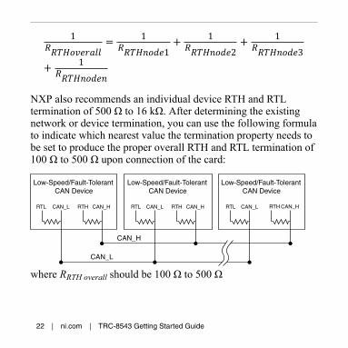
1 = 11 + 12 + 13+ 1NXP also recommends an individual device RTH and RTLtermination of 500 Ω to 16 kΩ. After determining the existingnetwork or device termination, you can use the following formulato indicate which nearest value the termination property needs tobe set to produce the proper overall RTH and RTL termination of100 Ω to 500 Ω upon connection of the card:
RTL CAN_L RTH CAN_H RTL RTLCAN_L RTH CAN_H CAN_L RTH CAN_H
CAN_H
CAN_L
Low-Speed/Fault-TolerantCAN Device
Low-Speed/Fault-TolerantCAN Device
Low-Speed/Fault-TolerantCAN Device
where RRTH overall should be 100 Ω to 500 Ω
22 | ni.com | TRC-8543 Getting Started Guide
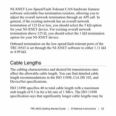
NI-XNET Low-Speed/Fault-Tolerant CAN hardware featuressoftware selectable bus termination resistors, allowing you toadjust the overall network termination through an API call. Ingeneral, if the existing network has an overall networktermination of 125 Ω or less, you should select the 5 kΩ optionfor your NI-XNET device. For existing overall networktermination above 125 Ω, you should select the 1 kΩ terminationoption for your NI-XNET device.
Onboard termination on the low-speed/fault-tolerant ports of theTRC-8543 is set through the NI-XNET software to either 1.11 kΩor 4.99 kΩ.
Cable LengthsThe cabling characteristics and desired bit transmission ratesaffect the allowable cable length. You can find detailed cablelength recommendations in the ISO 11898, CiA DS 102, andDeviceNet specifications.
ISO 11898 specifies 40 m total cable length with a maximumstub length of 0.3 m for a bit rate of 1 Mb/s. The ISO 11898specification says that significantly longer cable lengths may be
TRC-8543 Getting Started Guide | © National Instruments | 23
allowed at lower bit rates, but you should analyze each node forsignal integrity problems.
Number of CAN Nodes
High-Speed/Flexible Data-Rate CANThe maximum number of nodes depends on the electricalcharacteristics of the nodes on the network. If all nodes meet theISO 11898 requirements, you can connect at least 30 nodes to thebus. You can connect higher numbers of nodes if the nodes’electrical characteristics do not degrade signal quality belowISO 11898 signal level specifications.
The TRC-8543 electrical characteristics allow at least 110 CANports on a network.
Low-Speed/Fault-Tolerant CANThe maximum number of nodes depends on the electricalcharacteristics of the nodes on the network. If all of the nodesmeet the requirements of Low-Speed/Fault-Tolerant CAN, up to32 nodes may be connected to the bus.
24 | ni.com | TRC-8543 Getting Started Guide

TRC-8543 Hardware OverviewThe TRC-8543 has one full-featured CAN port that is isolatedfrom the host it is plugged into. Software can select betweeneither an NXP TJA1043T High-Speed CAN transceiver or NXPTJA1055T Low-Speed/Fault-Tolerant CAN transceiver bycontrolling on-board relays. The TJA1043T is fully compatiblewith the ISO 11898 standard and supports baud rates up to2 Mbps. The NI-XNET driver enables baud rates up to 8 Mbps.The TJA1055T is fully compatible with the ISO 11898 standardand supports baud rates up to 125 Kbps.
Figure 9. TRC-8543 Hardware Overview
IsolationBarrier
To CAN Bus
To Host Port
Transceiver
TRC-8543 Getting Started Guide | © National Instruments | 25
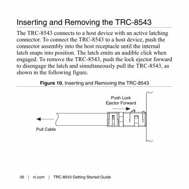
Inserting and Removing the TRC-8543The TRC-8543 connects to a host device with an active latchingconnector. To connect the TRC-8543 to a host device, push theconnector assembly into the host receptacle until the internallatch snaps into position. The latch emits an audible click whenengaged. To remove the TRC-8543, push the lock ejector forwardto disengage the latch and simultaneously pull the TRC-8543, asshown in the following figure.
Figure 10. Inserting and Removing the TRC-8543
Push LockEjector Forward
Pull Cable
26 | ni.com | TRC-8543 Getting Started Guide

TRC-8543 LEDsThe TRC-8543 includes two LEDs to help you monitor hardwareand bus status. LED 1 primarily indicates whether the hardwareis currently in use. LED 2 primarily indicates the activityinformation of the connected bus. Each LED can display twocolors (red or green), which display in the following fourpatterns:
Table 5. LED Pattern Definitions
Pattern Meaning
Off No LED illumination
Solid LED fully illuminated
Blink Blinks at a constant rate of several times per second
Activity Blinks in a pseudo-random pattern
TRC-8543 Getting Started Guide | © National Instruments | 27
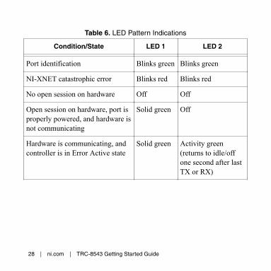
Table 6. LED Pattern Indications
Condition/State LED 1 LED 2
Port identification Blinks green Blinks green
NI-XNET catastrophic error Blinks red Blinks red
No open session on hardware Off Off
Open session on hardware, port isproperly powered, and hardware isnot communicating
Solid green Off
Hardware is communicating, andcontroller is in Error Active state
Solid green Activity green(returns to idle/offone second after lastTX or RX)
28 | ni.com | TRC-8543 Getting Started Guide

Table 6. LED Pattern Indications (Continued)
Condition/State LED 1 LED 2
Hardware is communicating, andcontroller is in Error Passive state
Solid green Activity red (returnsto idle/off onesecond after last TXor RX)
Hardware is running, andcontroller transitioned to bus off
Solid green Solid red
TRC-8543 SpecificationsThe following specifications are typical for the range -40 °C to70 °C unless otherwise noted.
TRC-8543 Getting Started Guide | © National Instruments | 29

High-Speed/Flexible Data-Rate CANCharacteristicsTransceiver NXP TJA1043TMax certified baud rate 2 MbpsInput voltage limitsCAN_H, CAN_L bus lines
-27 VDC to +40 VDC
Output voltage limitCAN_H, CAN_L bus lines
5 VDC
MTBF Contact NI for Bellcore MTBFspecifications at othertemperatures or MIL-HDBK-217F specifications.
Low-Speed/Fault-Tolerant CAN CharacteristicsTransceiver NXP TJA1055TMax baud rate 125 KbpsCAN_H, CAN_L bus linesvoltage
-27 VDC to +40 VDC
30 | ni.com | TRC-8543 Getting Started Guide

CAN Supply voltage range(VSUP)
+9 VDC to +30 VDC
MTBF Contact NI for Bellcore MTBFspecifications at othertemperatures or for MIL-HDBK-217F specifications.
TRC-8543 Getting Started Guide | © National Instruments | 31

Power RequirementsThermal dissipation(at 70 °C)
700 mW max (Low-Speed/Fault-Tolerant fault condition);550 mW max (High-Speedactive mode); 440 mW typical(High-Speed active mode);333 mW typical (Low-Speed/Fault-Tolerant active mode)
Power consumption fromTRC-8543 host
550 mW max (High-Speedactive mode); 440 mW typical(High-Speed active mode);310 mW max (Low-Speed/Fault-Tolerant active mode);245 mW typical (Low-Speed/Fault-Tolerant active mode)
Power consumption fromVSUP
320 mW max (Low-Speed/Fault-Tolerant fault condition);90 mW typical (Low-Speed/Fault-Tolerant active mode)
32 | ni.com | TRC-8543 Getting Started Guide
Note Power on VSUP is required for Low-Speed/Fault-Tolerant CAN operation.
Physical CharacteristicsTo clean the TRC-8543, wipe it with a dry towel.Weight 70 g (2.5 oz)Length 447 mm to 462 mm
(17.6 in. to 18.2 in.)D-Sub connector jackscrewmaximum torque
0.56 N · m (5.0 lb · in.)
Safety
Maximum Voltage1
Connect only the voltages that are within these limits.
Port-to-COM -27 VDC to +40 VDC max,Measurement Category I
1 The maximum voltage that can be applied or output without creating a safetyhazard.
TRC-8543 Getting Started Guide | © National Instruments | 33

Measurement Category I is for measurement performed oncircuits not directly connected to the electrical distribution systemreferred to as MAINS voltage. MAINS is a hazardous liveelectrical supply system that powers equipment. This category isfor measurements of voltages from specially protected secondarycircuits. Such voltage measurements include signal levels, specialequipment, limited-energy parts of equipment, circuits poweredby regulated low-voltage sources, and electronics.
Caution Do not connect to signals or use formeasurements within Measurement Categories II, III,or IV.
Note Measurement Categories CAT I and CAT O(Other) are equivalent. These test and measurementcircuits are not intended for direct connection to theMAINs building installations of MeasurementCategories CAT II, CAT III, and CAT IV.
Isolation Voltage
Port-to-earth groundContinuous 60 VDC, Measurement
Category I
34 | ni.com | TRC-8543 Getting Started Guide

Note The TRC-8543 COM signals are not connectedto the host port ground.
Safety and Hazardous Locations StandardsThis product is designed to meet the requirements of thefollowing electrical equipment safety standards for measurement,control, and laboratory use:• IEC 61010-1, EN 61010-1• UL 61010-1, CSA 61010-1• EN 60079-0:2012, EN 60079-15:2010• IEC 60079-0: Ed 6, IEC 60079-15; Ed 4• UL 60079-0; Ed 6, UL 60079-15; Ed 4• CSA 60079-0:2011, CSA 60079-15:2012
Note For UL and other safety certifications, refer tothe product label or the Online Product Certificationsection.
TRC-8543 Getting Started Guide | © National Instruments | 35

Hazardous LocationsU.S. (UL) Class I, Division 2, Groups A,
B, C, D, T4; Class I, Zone 2,AEx nA IIC T4
Canada (C-UL) Class I, Division 2, Groups A,B, C, D, T4; Class I, Zone 2, ExnA IIC T4
Europe (DEMKO) Ex nA IIC T4 Gc
36 | ni.com | TRC-8543 Getting Started Guide

EnvironmentalRefer to the manual for the host you are using for moreinformation about meeting these specifications.
Operatingtemperature2
(IEC 60068-2-1, IEC 60068-2-2)
-40 °C to 70 °C
Storagetemperature2
(IEC 60068-2-1, IEC 60068-2-2)
-40 °C to 85 °C
Ingress protection IP40Operating humidity(IEC 60068-2-56)
10% RH to 90% RH,noncondensing
Storage humidity(IEC 60068-2-56)
5% RH to 95% RH,noncondensing
2 Similar to other standard PVC cables, this product’s cable becomes less ductileat low temperatures. Preroute and secure the cable while flexible to avoidpremature failure.
TRC-8543 Getting Started Guide | © National Instruments | 37
Pollution Degree(IEC 60664)
2
Maximum altitude 5,000 m
Indoor use only.
Shock and VibrationTo meet these specifications, you must securely mount yourTRC-8543 and ensure all cables and connectors have properstrain relief.
Operating vibrationRandom(IEC 60068-2-64)
5 grms, 10 Hz to 500 Hz
Sinusoidal(IEC 60068-2-6)
5 g, 10 Hz to 500 Hz
Operating shock(IEC 60068-2-27)
30 g, 11 ms half sine;50 g, 3 ms half sine;18 shocks at 6 orientations
38 | ni.com | TRC-8543 Getting Started Guide

Electromagnetic CompatibilityThis product meets the requirements of the following EMCstandards for electrical equipment for measurement, control, andlaboratory use:• EN 61326-1 (IEC 61326-1): Class A emissions; Industrial
immunity• EN 55011 (CISPR 11): Group 1, Class A emissions• EN 55022 (CISPR 22): Class A emissions• EN 55024 (CISPR 24): Immunity• AS/NZS CISPR 11: Group 1, Class A emissions• AS/NZS CISPR 22: Class A emissions• FCC 47 CFR Part 15B: Class A emissions• ICES-001: Class A emissions
Note In the United States (per FCC 47 CFR), Class Aequipment is intended for use in commercial, light-industrial, and heavy-industrial locations. In Europe,Canada, Australia and New Zealand (per CISPR 11)Class A equipment is intended for use only in heavy-industrial locations.
TRC-8543 Getting Started Guide | © National Instruments | 39

Note Group 1 equipment (per CISPR 11) is anyindustrial, scientific, or medical equipment that doesnot intentionally generate radio frequency energy forthe treatment of material or inspection/analysispurposes.
Note For EMC declarations and certifications, andadditional information, refer to the Online ProductCertification section.
CE Compliance This product meets the essential requirements of applicableEuropean Directives, as follows:• 2014/35/EU; Low-Voltage Directive (safety)• 2014/30/EU; Electromagnetic Compatibility Directive
(EMC)• 2014/34/EU; Potentially Explosive Atmospheres (ATEX)
Online Product CertificationRefer to the product Declaration of Conformity (DoC) foradditional regulatory compliance information. To obtain productcertifications and the DoC for this product, visit ni.com/
40 | ni.com | TRC-8543 Getting Started Guide

certification, search by model number or product line, and clickthe appropriate link in the Certification column.
Environmental ManagementNI is committed to designing and manufacturing products in anenvironmentally responsible manner. NI recognizes thateliminating certain hazardous substances from our products isbeneficial to the environment and to NI customers.
For additional environmental information, refer to the MinimizeOur Environmental Impact web page at ni.com/environment. Thispage contains the environmental regulations and directives withwhich NI complies, as well as other environmental informationnot included in this document.
Waste Electrical and Electronic Equipment (WEEE)EU Customers At the end of the product life cycle, allNI products must be disposed of according to locallaws and regulations. For more information about howto recycle NI products in your region, visit ni.com/environment/weee.
TRC-8543 Getting Started Guide | © National Instruments | 41
电子信息产品污染控制管理办法(中国 RoHS)中国客户 National Instruments 符合中国电子信息产品中限制使用某些有害物质指令(RoHS)。关于National Instruments 中国 RoHS 合规性信息,请登录 ni.com/environment/rohs_china。(Forinformation about China RoHS compliance, go toni.com/environment/rohs_china.)
Worldwide Support and ServicesThe NI website is your complete resource for technical support.At ni.com/support, you have access to everything fromtroubleshooting and application development self-help resourcesto email and phone assistance from NI Application Engineers.
Visit ni.com/services for NI Factory Installation Services, repairs,extended warranty, and other services.
Visit ni.com/register to register your NI product. Productregistration facilitates technical support and ensures that youreceive important information updates from NI.
42 | ni.com | TRC-8543 Getting Started Guide

A Declaration of Conformity (DoC) is our claim of compliancewith the Council of the European Communities using themanufacturer’s declaration of conformity. This system affords theuser protection for electromagnetic compatibility (EMC) andproduct safety. You can obtain the DoC for your product byvisiting ni.com/certification. If your product supports calibration,you can obtain the calibration certificate for your product at ni.com/calibration.
NI corporate headquarters is located at11500 North Mopac Expressway, Austin, Texas, 78759-3504. NIalso has offices located around the world. For telephone supportin the United States, create your service request at ni.com/supportor dial 1 866 ASK MYNI (275 6964). For telephone supportoutside the United States, visit the Worldwide Offices section of ni.com/niglobal to access the branch office websites, whichprovide up-to-date contact information, support phone numbers,email addresses, and current events.
TRC-8543 Getting Started Guide | © National Instruments | 43

Refer to the NI Trademarks and Logo Guidelines at ni.com/trademarks for information on NItrademarks. Other product and company names mentioned herein are trademarks or trade namesof their respective companies. For patents covering NI products/technology, refer to theappropriate location: Help»Patents in your software, the patents.txt file on your media, or theNational Instruments Patent Notice at ni.com/patents. You can find information about end-userlicense agreements (EULAs) and third-party legal notices in the readme file for your NI product.Refer to the Export Compliance Information at ni.com/legal/export-compliance for the NIglobal trade compliance policy and how to obtain relevant HTS codes, ECCNs, and other import/export data. NI MAKES NO EXPRESS OR IMPLIED WARRANTIES AS TO THE ACCURACY OFTHE INFORMATION CONTAINED HEREIN AND SHALL NOT BE LIABLE FOR ANY ERRORS.U.S. Government Customers: The data contained in this manual was developed at privateexpense and is subject to the applicable limited rights and restricted data rights as set forth in FAR52.227-14, DFAR 252.227-7014, and DFAR 252.227-7015.
© 2016 National Instruments. All rights reserved.
376295A-01 Dec16