Embed Size (px)
Citation preview

B1WD-3310-01ENZ0(00)March 2014
Windows
FUJITSU SoftwarePowerFORM V11.0
Getting Started

PrefacePowerFORM is a tool for designing graphical reports using NetCOBOL print files.
Audience
This manual is for anyone intending to use PowerFORM. It assumes the reader has a reasonable understanding of COBOL.
How this Manual is OrganizedThis manual consists of the following chapters and appendixes:
Chapter Contents
Chapter 1. Introduction to PowerFORM Gives an overview of the PowerFORM product, adescription of what's new in V11.
Chapter 2. Understanding PowerFORM Concepts Explains the key concepts you need to know touse PowerFORM.
Chapter 3. Getting Started with PowerFORM. Describes all parts of the PowerFORM interfaceand walks you through the creation of your firstform.
Chapter 4. Programming with PowerFORM. Explains how use the forms created withPowerFORM from COBOL programs.
Chapter 5. Using PowerFORM Tips on using a number of PowerFORM features.
How to Use This ManualFirst-time users of PowerFORM should read the introductory comments in Chapter 1, then proceed through Chapters 2 to 5.
Experienced PowerFORM users should review the new features list and upgrading notes in Chapter 1, review the new interface detailsin Chapter 3, and check the topics of interest in Chapter 5.
Conventions Used in this Manual
This manual uses the following typographic conventions.
Example of Convention Description
setup Characters you enter appear in bold.
Program-name Underlined text indicates a place holder forinformation you supply.
ENTER Small capital letters are used for the nameof keys and key sequences such as ENTER andCTRL+R. A plus sign (+) indicates acombination of keys.
... Ellipses indicate the item immediatelypreceding can be specified repeatedly.
Edit, Literal Names of pulldown menus and optionsappear with the initial letter capitalized.
[def] Indicates that the enclosed item may beomitted.
- i -

or {ABC|DEF}Indicates that one of the enclosed items(delimited by |) is to be selected. If items areomitted the underlined item is assumed.
CHECK
WITH PASCAL LINKAGE
ALL
PARAGRAPH-ID
COBOL
ALL
Commands, statements, clauses, andoptions you enter or select appear inuppercase. Program section names, andsome proper names also appear inuppercase. Defaults are underlined.
PROCEDURE DIVISION:
ADD 1 TO POW-FONTSIZE OF LABEL1.
IF POW-FONTSIZE OF LABEL1 > 70 THEN
MOVE 1 TOW POW-FONTSIZE OF LABEL1.
END-IF.
This font is used for examples of programcode.
The sheet acts as an application creation window. Italics are occasionally used for emphasis.
"Fujitsu COBOL Language Reference"
Refer to "Compile Options" in Chapter 5.
References to other publications or sectionswithin publications are in quotation marks.
Product Names
Product Name Abbreviation
Microsoft(R) Windows Server(R) 2012 R2 Datacenter
Microsoft(R) Windows Server(R) 2012 R2 Standard
Microsoft(R) Windows Server(R) 2012 R2 Essentials
Microsoft(R) Windows Server(R) 2012 R2 Foundation
Windows Server 2012 R2
Microsoft(R) Windows Server(R) 2012 Datacenter
Microsoft(R) Windows Server(R) 2012 Standard
Microsoft(R) Windows Server(R) 2012 Essentials
Microsoft(R) Windows Server(R) 2012 Foundation
Windows Server 2012
Microsoft(R) Windows Server(R) 2008 R2 Standard
Microsoft(R) Windows Server(R) 2008 R2 Enterprise
Microsoft(R) Windows Server(R) 2008 R2 Foundation
Microsoft(R) Windows Server(R) 2008 R2 Datacenter
Windows Server 2008 R2
Windows(R) 8.1
Windows(R) 8.1 Pro
Windows(R) 8.1 Enterprise
Windows 8.1(x64)
Windows(R) 8
Windows(R) 8 Pro
Windows(R) 8 Enterprise
Windows 8(x64)
Windows(R) 7 Home Premium
Windows(R) 7 Professional
Windows 7(x64)
- ii -

Windows(R) 7 Enterprise
Windows(R) 7 Ultimate
- In this manual, when all the following products are indicates, it is written as "Windows" or "Windows(x64)".
- Windows Server 2012 R2
- Windows Server 2012
- Windows Server 2008 R2
- Windows 8.1(x64)
- Windows 8(x64)
- Windows 7(x64)
Related Manuals
Other manuals of particular relevance to PowerFORM users:
NetCOBOL Language ReferenceNetCOBOL User's GuidePowerFORM Runtime Reference
TrademarksMicrosoft, Windows Server, and Windows are either registered trademarks or trademarks of Microsoft Corporation in the United Statesand/or other countries.
NetCOBOL is a trademark or registered trademark of Fujitsu Limited or its subsidiaries in the United States or other countries or inboth.
Other product names are trademarks or registered trademarks of each company. Trademark indications are omitted for some systemand product names described in this manual.
- iii -
ContentsChapter 1 Introduction to PowerFORM.................................................................................................................................................1
1.1 Overview of PowerFORM............................................................................................................................................................ 11.2 What's New in PowerFORM V11?................................................................................................................................................21.3 Upgrading from PowerFORM V1,V2,and V6................................................................................................................................4
Chapter 2 Understanding PowerFORM Concepts..................................................................................................................................52.1 Understanding PowerFORM in the Development and Execution Processes................................................................................52.2 Understanding PowerFORM Descriptors and Overlays................................................................................................................72.3 Understanding PowerFORM Partitions....................................................................................................................................... 8
Chapter 3 Getting Started with PowerFORM...................................................................................................................................... 113.1 The PowerFORM Interface........................................................................................................................................................ 11
3.1.1 Overview........................................................................................................................................................................... 113.1.2 Interface Details................................................................................................................................................................11
3.1.2.1 Form Layout Area.......................................................................................................................................................113.1.2.2 Format Toolbar...........................................................................................................................................................123.1.2.3 Insert Field Toolbar.................................................................................................................................................... 123.1.2.4 Insert Partition Object Toolbar................................................................................................................................... 133.1.2.5 Insert Overlay Object Toolbar..................................................................................................................................... 143.1.2.6 Menu Bar................................................................................................................................................................... 153.1.2.7 Name of Descriptor being Edited............................................................................................................................... 163.1.2.8 Partition Name List.................................................................................................................................................... 163.1.2.9 Partition Labels..........................................................................................................................................................163.1.2.10 Pop-up Menus.......................................................................................................................................................... 163.1.2.11 Rulers.......................................................................................................................................................................163.1.2.12 Standard Toolbar......................................................................................................................................................173.1.2.13 Status Bar.................................................................................................................................................................183.1.2.14 Tabs for Selecting the Form View............................................................................................................................. 18
3.2 Creating a Report.....................................................................................................................................................................183.2.1 Step-by-Step Instructions.................................................................................................................................................. 19
Chapter 4 Programming with PowerFORM.........................................................................................................................................374.1 Overview..................................................................................................................................................................................374.2 Coding for PowerFORM............................................................................................................................................................ 374.3 Sample Program Source...........................................................................................................................................................404.4 Building and Running with PowerFORM.................................................................................................................................. 444.5 UNIX Considerations................................................................................................................................................................ 46
Chapter 5 Using PowerFORM............................................................................................................................................................. 475.1 Populating Wizard Data Item Categories................................................................................................................................. 475.2 Editing Wizard Data Items....................................................................................................................................................... 495.3 Choosing the Default Date Format ..........................................................................................................................................495.4 Selecting Borders and Shading Colors......................................................................................................................................495.5 Configuring the Color Palettes................................................................................................................................................. 495.6 Clearing the Preview Layout Area............................................................................................................................................ 505.7 Repeating Fields and Objects...................................................................................................................................................505.8 Partition and Overlay Lines......................................................................................................................................................525.9 Defining Record Layouts.......................................................................................................................................................... 525.10 Using Common Records......................................................................................................................................................... 525.11 Using the Wizard Label Patterns............................................................................................................................................ 535.12 PowerFORM Questions...........................................................................................................................................................53
- iv -

Index................................................................................................................................................................................................. 55
- v -

Chapter 1 Introduction to PowerFORMThis chapter introduces you to the latest version of PowerFORM. It gives:
- An overview of how you can use PowerFORM.
- Lists of new features for those upgrading from earlier versions.
1.1 Overview of PowerFORMPowerFORM is a tool designed to help you produce good-looking reports that can be printed in a number of environments. It is tailoredto work with COBOL applications. Programming for PowerFORM is almost identical to writing a regular print file.
PowerFORM gives highly flexible formatting and helps you include most graphics that would otherwise have to be printed on pre-printed forms.
With little effort you can convert character-based reports like that shown in Figure 1.1, to a report with the fonts of your choice,graphical borders, dividing lines and colors, like that shown in Figure 1.2.
Figure 1.1 A Character-based Report
Figure 1.2 A Report Created with PowerFORM
- 1 -

Consider the possibilities of using PowerFORM, compared to regular print files that have few formatting options and often requirespecial pre-printed forms for any graphics.
Better, Faster, Easier Reports with PowerFORM
PowerFORM helps you:
- Create forms with ruled and curved lines, shading, and graphics.
- Tailor character size, density and printing pitch.
- Incorporate color into your reports.
- Create professional looking reports
- Ease the creation and maintenance of reports.
PowerFORM Environments
PowerFORM runs in Windows (Windows 7, Windows 8, Windows 8.1, Windows Server 2008 R2, Windows Server 2012 and WindowsServer 2012 R2) environments and supports development of forms to run on Windows and UNIX environments. Check with yourPowerFORM sales representative for the latest list of supported platforms.
Getting Started with PowerFORM
This manual aims to give you a quick start to using PowerFORM while covering all the key facts you need to be fully productive withthe product.
It guides you through the product and its concepts, helps you create your first report and uses a sample program to show you how toprogram with PowerFORM. It is arranged as follows:
The remainder of Chapter 1 provides information on the latest features added to PowerFORM.
Chapter 2 introduces you to the key PowerFORM concepts on which your reports will be built.
Chapter 3 explains the various parts of the PowerFORM main window and guides you through the creation of a professional report.
Chapter 4 tells you how to program with PowerFORM.
Chapter 5 lists a number of suggestions for becoming more productive with PowerFORM and provides help on commonly askedquestions.
Have fun discovering the power of PowerFORM!
1.2 What's New in PowerFORM V11?PowerFORM V11. contains a number of significant enhancements over V6, making the form design easier and increasing your optionsfor creating excellent printed reports.
The enhancements in PowerFORM V11 are:
Features that Enhance the Printed Forms
Improvements of Expressions on Forms
- You can specify values for barcodes: the intercharacter gap (the gap between the characters), the ratio of the width of narrowbars and wide bars, and the drawing methods for the quiet zone (margins on a barcode's left and right ends).
- You can specify [Suppress any Decimal Places] for the numeric field.
- The visible fields can now include radio buttons and checkboxes.
- You can specify strikethroughs for fields.
- The maximum value of the data length for the following fields has been expanded.
- UCS2 fields: 998 to 2994
- 2 -

- Block UCS2 fields: 998 to 9998
- Mixed fields: 999 to 2997
- Block mixed fields,Block alphanumeric fields,Record fields: 999 to 9999
- You can define the barcodes for EAN-128 (Convenience Store).
- You can define the forms in free frame format.
- You can define a barcode for Code 3 of 9 (EIAJ Compliant).
- You can specify the orientation of a string for the following fields: static fields, numeric fields, alphanumeric fields, UCS2 fields,mixed fields, OCR-B fields, date fields, and time fields, as well as overlay text.
- You can specify word wrap for block alphanumeric fields, block UCS2 fields and block mixed fields
- You can specify the text shrinking of block alphanumeric fields, block UCS2 fields and block mixed fields
- You can specify the automatic expansion of block alphanumeric fields, block UCS2 fields, block mixed fields and partitions.
- You can specify multiple byte size for currency symbols in the numeric fields.
- You can specify the following for currency symbols: [$--,---9], [ZZZ,ZZ9$], [ZZZ,ZZ9$CR], [ZZZ,ZZ9CR$], [ZZZ,ZZ9$DB],[ZZZ,ZZ9DB$], [ZZZ,ZZ9$-], [ZZZ,ZZ9-$], [-ZZZ,ZZ9$], [---,--9$].
- You can specify the edit format for decimal places of numeric fields.
- You can specify [Float Sign/Currency Symbol Before Value] for the edit format.
- You can specify [Use Native Resolution] or [Transparency] for image fields.
- The value of a character pitch can be specified to 1.5 for the following: static fields, UCS2 fields, mixed fields, date fields andtime fields.
- You can specify [OutputID] for static fields.
- The number of digits for numeric fields has been expanded to 31 digits.
Improvements on the Form Designing Support Functions
- When preparing the field information (names, data lengths, digits, types) in INI files beforehand, you can easily define thefields by dragging and dropping items from the field entry list on the edit window.
- You can use wizard to add block UCS2 fields, block alphanumeric fields, block mixed fields, OCR-B fields, radio buttons, andcheckboxes.
- You can change the following fields from record to visible fields: block UCS2 fields, block alphanumeric fields, block mixedfields, OCR-B fields, and radio buttons, as well as checkboxes.
- When creating graphical content such as a table,it is possible to automatically connect the created line with the one lying onits extension.
- Multiple fields or graphics can be placed together to fit into the constraint spacing of the grid.
- You can easily create a horizontal/vertical line by defining a line while the [Shift] key is held down.
- The improved shortcut key functions enable you to define forms more efficiently than ever before.
- The quick handle to expand/close down fields is added to enlarge the size of the edit area with a single operation.
- The zoom function of the edit window has been improved.
- The shape of the mouse cursor when placed over the selectable objects has been revised so that the operations on the editwindow are visually more understandable.
Other Improvements
- The command is available to convert the form descriptor (.pmd) created by PowerFORM to the one handled in UTF-32.
- 3 -

1.3 Upgrading from PowerFORM V1,V2,and V6The format of the form descriptor created by PowerFORM V1,V2 or V6 is converted when imported by PowerFORM V11.0.0.
The conversion does not affect the output form or a COBOL application.
However, the converted form descriptor cannot be handled in PowerFORM V1,V2 or V6.
Take note of the following below when importing the form descriptor with PowerFORM V11.
- The text field of the form descriptor when imported with PowerFORM V1, V2, or V6 is a Mixed Text Field.
- Because font information is not included in the form descriptor when imported with Power-FORM V1, the font face default isalready set.
- 4 -

Chapter 2 Understanding PowerFORM ConceptsPowerFORM is a straightforward tool to use both for designing and programming printed reports. You only need to understand a fewsimple concepts to master the tool and reap the full benefits. The key concepts are:
- How PowerFORM fits into your development and execution processes
- PowerFORM descriptor and overlay files
- PowerFORM partitions
This chapter explains these concepts and the next chapter shows you how to put them into action to create a print report.
2.1 Understanding PowerFORM in the Development and ExecutionProcesses
PowerFORM provides an interactive environment for designing print reports. It creates:
- COPY text to be included in your COBOL programs at compile time,
- Form descriptors and overlays that define the appearance and contents of the reports, and are used at execution time.
Figure 2.1 shows how PowerFORM fits into the COBOL development and execution environments. The numbers show the parts involvedin the steps listed following the figure.
- 5 -

Figure 2.1 PowerFORM and the Development and Execution Processes
The steps in the development and execution processes are:
1. Design the print report using PowerFORM
2. Confirm the appearance of the report either by viewing it on-line or printing it on a printer. PowerFORM creates the descriptor,and overlay required for printing by the PowerFORM runtime.
3. Create the code to manage the printing. The COBOL compiler accesses a COPY library containing the record definitions forinterfacing with the form descriptor. The COPY library is held in the form descriptor file.
4. Create printer information files for each environment in which the application will run.
5. Execute the application. The COBOL runtime recognizes the PowerFORM print file and invokes the PowerFORM runtime. ThePowerFORM runtime uses the form descriptor, overlay and printer information files to prepare and print the information outputby the COBOL application.
Using PowerFORM for UNIX Applications
You can use PowerFORM to design print reports for use with UNIX applications. The development environment only runs on Windows,but the runtime supporting files can be taken to the UNIX environment for use with UNIX applications.
PowerFORM supports PostScript and PCL printers in the UNIX environment.
The diagram below illustrates using PowerFORM for UNIX applications.
- 6 -

Figure 2.2 Using PowerFORM for UNIX Applications
2.2 Understanding PowerFORM Descriptors and OverlaysPowerFORM stores the layouts of your print reports in two files: the descriptor file and the overlay file. The descriptor file has a .PMDextension and the overlay file has a .OVD extension.
The overlay file is best thought of as a background on which the information contained in the descriptor file is printed. The overlaycontains static text and graphics that are fixed in position on the page. The descriptor contains all the variable information and canalso contain static text and graphics that have variable positions or are more conveniently kept with the variable information.
When creating a print file you can use different overlays for different pages, but once the overlay is selected the background for aparticular page is set. The foreground is then determined by which parts (partitions - see the next section) of the descriptor file areoutput by the program.
You will see descriptors referred to as "form descriptors" or just "forms", and overlays as "form overlays" and sometimes as "overlaydescriptors".
What is actually printed is the combination of the background form overlay and the foreground form descriptor, as illustrated in Figure2.3. The application supplies the variable information, which the PowerFORM runtime adds to the static fields in the form descriptor.Then the runtime merges these with the form overlay to produce the final print result.
- 7 -

Figure 2.3 How Form Descriptors and Overlays Combine.
When you design your reports in PowerFORM you place descriptor and overlay objects on the same work surface. Thus you can be surethat alignments are correct. When you save your report PowerFORM creates both the descriptor (.PMD) and overlay (.OVD) files.
All the fields, partition lines and partition rectangles are stored in the form descriptor. All the other drawing objects, such as overlaycharacters, lines and ellipses, are stored in the form overlay.
2.3 Understanding PowerFORM PartitionsIn PowerFORM you create reports, or forms, as combinations of partitions. A simple form may have a single, fixed-position partition.A complex form may have many partitions some fixed in position, others of variable position. A partition is a group of lines that areoutput together by your program. Partitions can be either fixed or floating.
A fixed partition has a fixed location on the page. Whenever it is printed it will always appear in the same place on the page - forexample at the top or at the bottom. Fixed partitions are therefore mostly used for page headers and footers.
A floating partition is printed below the last partition that was printed. You can therefore print many instances of a floating partitionon a single page - each instance is printed below the previous instance. Floating partitions are used for information such as detaillines, sub-total and total lines.
Figure 2.4 below shows a report with heading, detail, sum and total lines. The left hand block shows the partitions set up in PowerFORM,the right hand block shows the actions taken by the program, and the middle block shows, schematically, the print output.
- 8 -

Figure 2.4 Example Showing Fixed and Floating Partitions
PowerFORM uses an anchor symbol, , to denote fixed partitions, and a life belt symbol, , to denote floating partitions.
Partitions and the PowerFORM Wizard
The PowerFORM Wizard offers you the choice of four report patterns:
- Free Frame
- Fixed
- Head/Body/Tail
- Labels
- Multiple Parts
Essentially these are different combinations of partition types, so the Wizard gives you a quick way of creating reports based on oneof these patterns.
The Fixed report pattern consists of a single fixed partition. Use this pattern for reports that have no repeating lines.
The Head/Body/Tail report pattern lets you select from:
- a single fixed partition for your report heading,
- a single floating partition for repeated lines, and
- a single fixed partition for the report tail.
The Wizard places headings for the repeated lines in the Head partition and sizes each partition according to the amount of data youplace in that partition.
The Labels patterns consist of a single fixed partition, but take advantage of the repeating rectangle feature to provide horizontaland vertical repeating data.
The Multiple Parts report pattern lets you select from:
- a single fixed partition for your report heading (offered after the other partitions in the wizard's sequence),
- a single fixed partition for your page heading,
- one or more control header floating partitions
- a single floating partition for detail lines
- one or more control footer floating partitions, and
- 9 -

- a single fixed partition for your report or page footer.
The Wizard places headings for the repeated lines in a control header partition and sizes each partition according to the amount ofdata you place in that partition.
The Free Frame lets you select from:
- Multiple parts that outputs in steps by class
- A part that outputs repetitive detailed horizontal lines
- A part that outputs the details of a different layout to one slip.
- 10 -

Chapter 3 Getting Started with PowerFORMThis chapter introduces you to the components of the PowerFORM main window and guides you through the creation of a report.
3.1 The PowerFORM Interface
3.1.1 OverviewFigure 3.1 shows the components of the PowerFORM interface.
Figure 3.1 The PowerFORM Interface
The main design or work area is the Form Layout Area. You can configure what is shown in the Form Layout Area using the All, Fixand Preview tabs and by selecting certain details from the View menu.
The Partition Name List and Record Name List pane lets you control how the report is segmented and how the data items are grouped.
The menu bar gives access to all PowerFORM functions through menus and dialog boxes. The functions are grouped logically andhave full text descriptions. The menu bar is therefore the best place to explore PowerFORM's functions.
The toolbars give one-click access to most of the frequently used functions. Once you feel confident in using a particular function, orfind that you are accessing a function frequently from the menu bar, you will want to learn the toolbar button for that function. Thiswill speed your work.
Use Tooltips to discover or check the function of each toolbar button. Hover the mouse pointer over the button for a second or more,and PowerFORM displays a tooltip describing the button's function.
The status bar displays various settings and provides helpful messages.
3.1.2 Interface DetailsThe components of the interface shown in Figure 3.1 are explained in detail in the sections below. The explanations are in alphabeticalorder, using the terms shown in Figure 3.1.
The explanations also include the pop-up menu, not shown in Figure 3.1.
3.1.2.1 Form Layout AreaThis is the main work area where you design your forms. Fields and graphic objects are placed in this area.
- 11 -

Use the tabs to change the view presented in the Form Layout Area. You can display both fixed and floating partitions (All), only fixedpartitions (Fixed) or create a mock-up of how your report will appear using Preview.
The following View menu functions also affect what is shown in the Form Layout Area: Show/Hide Partition, Hide All Partitions, ShowOverlay, Show Partition Lines, and Grid.
3.1.2.2 Format Toolbar
The Format Toolbar provides functions for formatting the currently selected text or graphics object:
- Select Font for currently selected field. Note that not all fonts are displayed in the form layout area
so the field may continue to be displayed in the default font. The font is applied when the report is printed.
Full font details, including color, width and characters per inch, can be configured using the field properties dialog (displayed bydouble clicking on the field in the Form Layout Area).
- Select Point Size for currently selected field.
- Toggle Text Bold/Not
- Toggle Text Italic/Not
- Toggle Text Underline/Not
- Selected String:Cross-out Line Set / Release
- Field Color - sets the color for the currently selected field, from the custom palette.
- Overlay Color - sets the border (left mouse button) and fill (right mouse button) colors of graphics objects.
- Line Weight and Style - changes line weight or line style.
- Pattern - Sets the fill pattern for the currently selected graphic object.
- Round corners - Selects a round-corners tool that you can use to round the corners of partition and overlay rectangles.
You can alter the curvature of the corners in the Properties dialog for rectangle objects or by changing the default values for drawingobjects from the Tools menu.
- Properties - Displays the properties dialog box for the currently selected object.
- Sets a frame link.
- Field font size cannot be changed by resizing a field with the mouse.
- Turns line auto-connection on/off.
3.1.2.3 Insert Field Toolbar
The Insert Field Toolbar lets you place fields in partitions. To insert a field:
1. Click on the appropriate button.
2. Move the mouse pointer to the intended top left position of the field in the Form Layout Area.
- 12 -

3. Click the left mouse button and drag the pointer to the intended bottom right position of the field.
4. Releasing the mouse button places the field on the form.
Supported fields are:
Static Text Field
Numeric Field
Text Field
UCS2 Field
Mixed Text Field
OCR-B Field
Block Static Field
Block Text Field
Block UCS2 Field
Block Mixed Text Field
Radio Button Field
Check Box Field
Barcode Field
Bitmap Field (referred to as a "built-in" field)
Date Field
Time Field
3.1.2.4 Insert Partition Object Toolbar
The Insert Partition Object Toolbar lets you place drawing objects in the Form Partition Layout Area. To place a drawing object on yourform:
1. Click on the toolbar button
2. Move the pointer to the starting position for the object.
3. Click to start drawing the object and drag to set the extent of the object.
4. Releasing the mouse button places the object on the form.
Drawing objects automatically become part of the form overlay, so place them exactly where you want them to appear on the page.
The drawing objects are:
- 13 -

Line
Rectangle
Three sides of a rectangle (right, bottom, left)
Three sides of a rectangle (bottom, left, top)
Three sides of a rectangle (left, top, right)
Three sides of a rectangle (top, right, bottom)
Two sides of a rectangle (bottom, left)
Two sides of a rectangle (left, top)
Two sides of a rectangle (top, right)
Two sides of a rectangle (right, bottom)
3.1.2.5 Insert Overlay Object Toolbar
The Insert Overlay Object Toolbar lets you place drawing objects in the Form Overlay Layout Area. To place a drawing object on yourform:
1. Click on the toolbar button
2. Move the pointer to the starting position for the object.
3. Click to start drawing the object and drag to set the extent of the object.
4. Releasing the mouse button places the object on the form.
Drawing objects automatically become part of the form overlay, so place them exactly where you want them to appear on the page.
The drawing objects are:
Overlay character - inserts static text in the overlay
Overlay Block Text
Line
Rectangle
Three sides of a rectangle (right, bottom, left)
Three sides of a rectangle (bottom, left, top)
Three sides of a rectangle (left, top, right)
Three sides of a rectangle (top, right, bottom)
- 14 -

Two sides of a rectangle (bottom, left)
Two sides of a rectangle (left, top)
Two sides of a rectangle (top, right)
Two sides of a rectangle (right, bottom)
Ellipse
Picture - inserts a bitmap of the object currently held in the clipboard.
3.1.2.6 Menu Bar
Provides access to all of PowerFORM's functions through drop-down menus and dialog boxes. PowerFORM also provides access tomany of these functions by other means such as toolbars and pop-up menus.
The functions are grouped on the menus as follows:
- Control menu button. Provides functions for manipulating form windows in the multiple document interface. For example, youcan have several forms open, each in its own document window, and use these functions for working with these windows.
File
- File level functions such as creating, opening, closing, printing, form properties and applying different overlay patterns.
Edit
- Editing functions such as undo, cut, copy, paste, and aligning items. Includes the ability to add common records and createmultiple copies of an item.
View
- Functions to configure what you see in PowerFORM's window. You can show or hide interface elements such as the toolbars, andselect which parts of the form definition are displayed in the Form Layout Area, such as the overlay and partition lines.
Insert
- Functions to add the available objects, such as text fields, partition lines, and partitions, to your form design.
Format
- Functions for editing the format of objects including their properties, the available colors, the order for overlapping objects, andwhether changes to one item's properties become the default for the next item that is inserted.Four functions (Field Fonts, Overlay Character Fonts, Partition Lines Format, and Drawing Objects Format) provide the ability toset properties when more than one object is selected.
Tools
- Functions for configuring defaults and the PowerFORM options.
Windows
- Functions for selecting and arranging windows when you have more than one form open.
Help
- Access to the PowerFORM help.
- 15 -

3.1.2.7 Name of Descriptor being Edited
PowerFORM displays the name of the descriptor currently being edited in the window title bar. You can edit multiple descriptors withinthe same PowerFORM session, using the Window menu to switch between descriptors.
3.1.2.8 Partition Name ListThe Partition Name List lists the partitions that make up the descriptor.
The anchor symbol, , indicates fixed partitions, and the life belt symbol, , indicates floating partitions.
Click on the + sign to expand the list to show the fields contained in that partition. On the View menu you can unselect "Show StaticFields" so that PowerFORM only displays variable data items.
In Preview view you drag partitions from the partition list to the Form Layout Area to show them in the Preview.
3.1.2.9 Partition LabelsThe Partition Labels show the name and extent of the partitions displayed in the Form Layout Area.
3.1.2.10 Pop-up MenusWhen the mouse pointer is over the Form Layout Area or the Partition/Record Name List pane, you can click the right mouse buttonto bring up a pop-up menu.
Partition Name List Pop-up
Form Layout Pop-up
Record Name List Pop-up
The pop-up menu provides quick access to common functions. Only those functions that apply to the current selection are enabled.
3.1.2.11 RulersThe Rulers show your position in the page measured from the top left corner.
You can turn the display of the rulers off or on by selecting or unselecting "Rulers" from the View menu.
- 16 -

You configure the units of measurement (inches or millimeters) using the View, Grid menu function.
3.1.2.12 Standard Toolbar
The Standard Toolbar provides the standard functions:
- New File
- Open File
- Save File
- Print Preview
- Cut
- Copy
- Paste
- Undo
- Redo
- Zoom Control - adjusts the enlargement factor for the form layout area.
- Gridlines On/Off
- Snap-to-Grid On/Off
- Toggle lock/unlock of frames/partitions for editing.
- Show Overlay On/Off
- Show Partition Lines On/Off
- Show/Hide Lines Between Layout Areas
- Show/Hide Template Image
- Show Preceding Report Page
- Show Next Report Page
- Allows Arrangement of the Layout Area When in Preview
Mode
- 17 -

3.1.2.13 Status Bar
The Status Bar gives information about the items selected or pointed at:
Amplified tool tips - gives an expanded explanation of the button or function under the pointer.
Auto-Join Lines on/off - displays "Auto-Join Lines" when Auto-Join Lines is turned on, otherwise is blank.
Snap on/off - displays "Snap to grid" when snap to grid is turned on, otherwise is blank.
Ruler unit - displays "Inch" when the ruler units are inches, and "mm" when the ruler units are centimeters, and "dot" when the rulerunits are dots.. (Set in the View, Grid menu function.)
Pointer position - horizontal and vertical position of the pointer, or of the top left corner of the object being dragged.
Selected field name - the name of the currently selected field.
Field length - length, in bytes, of the currently selected field.
3.1.2.14 Tabs for Selecting the Form View
Use these tabs to change the information presented in the Form Layout Area.
Complete - Shows all partitions stacked immediately underneath one another. For example, a fixed footer partition that is printedat the bottom of the page is displayed after the last floating partition - even if it is half-way up the page.
Fixed - Shows only fixed partitions, in the positions they will be printed on the page. If two or more fixed partitions overlap only thelast displayed partition is shown. To display one of the other partitions, hide the currently displayed partition and show the otherpartition.
Preview - Lets you get a feel for how your report will look by providing the ability to repeat floating partitions many times. Dragpartitions from the Partition List to have the partition displayed in the Preview.
PowerFORM displays the form overlay in all views of the report. The horizontal alignment of overlay objects with partition objects isbest checked in either the Fix or Preview views. The All view does not place partitions in their expected vertical positions.
You can drag the dividing lines between partitions in the Form Layout Area to change the heights of partitions.
You can change the positions of fixed partitions by dragging the partition label in either the Fix or Preview views.
3.2 Creating a ReportThis section takes you through all the steps to create a typical report. Figure 3.2 shows the end result.
- 18 -

Figure 3.2 The report you create in this section
3.2.1 Step-by-Step Instructions
A.Start PowerFORM
1. Select Start from the Windows task bar, then select Programs, Fujitsu NetCOBOL, PowerFORM.
B.Use the PowerFORM wizard to setup your starting layout.
1. From the File menu select New, or click the New button, , on the Standard toolbar.
PowerFORM displays the Create New Descriptor dialog box:
- 19 -

2. Select Wizard. This brings up the Wizard's introductory window.
3. Select Next.You progress to the paper size and orientation window.
4. Confirm the selections:Paper size: LetterOrientation: Portraitand select Next.
The Wizard now asks you to select the pattern for your report.
- 20 -

5. Select the Multiple Parts pattern, as our report requires several different partitions and select Next.
The wizard asks you to setup the descriptor details.
6. Enter "Sales Summary" in the Title field.
7. Change the number by Control Header to 0, confirm that Page Header and Page Footer are checked and that the number ofControl Footers is set to 1.
- 21 -

8. Select Next.
The Wizard displays the second descriptor details dialog, offering a report header. Our report does not have a report header,so...
- 22 -

9. Uncheck the Report Header and Footer checkboxes.
10. Click Next.
The Wizard now asks you to populate your report with data items.
11. Select the category Sample. The item list changes to show the items in the Sample category.
- 23 -

12. Place fields in the partitions by dragging (or double clicking) them from the item list and dropping them on the target partition.Place the Sample items in the partitions as shown in the following picture.
- 24 -

You can edit field information at this point.
13. Select PAGE-COUNT and click on the Property button to open the Property dialog box.
14. Change the field length from 4 to 3 and click OK.
15. Select Next.
16. On the Wizard concluding screen, check the Freeform Option checkbox. This will allow us to rename the partition names andchange the partition type. Then select the Finish button.
- 25 -

PowerFORM generates a descriptor with your selected partitions and data. It creates static text labels, based on the data itemnames, for all the data items. Labels for the detail line items are placed in the Page Header partition.
- 26 -
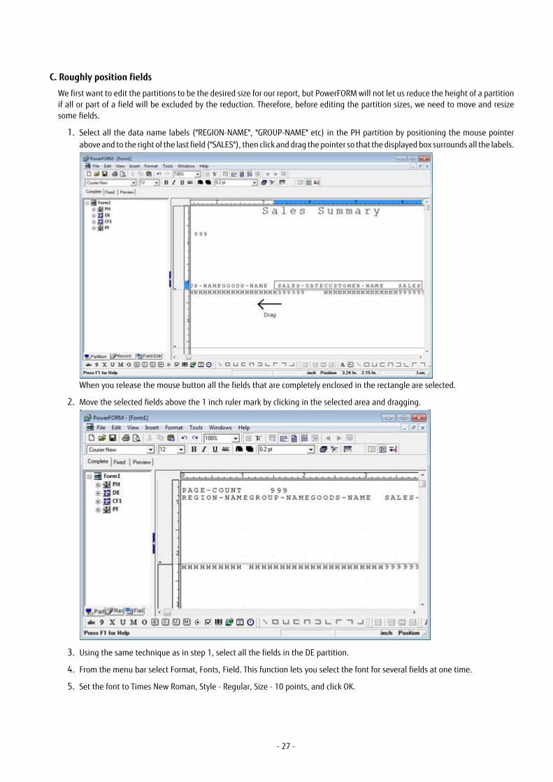
C. Roughly position fields
We first want to edit the partitions to be the desired size for our report, but PowerFORM will not let us reduce the height of a partitionif all or part of a field will be excluded by the reduction. Therefore, before editing the partition sizes, we need to move and resizesome fields.
1. Select all the data name labels ("REGION-NAME", "GROUP-NAME" etc) in the PH partition by positioning the mouse pointerabove and to the right of the last field ("SALES"), then click and drag the pointer so that the displayed box surrounds all the labels.
When you release the mouse button all the fields that are completely enclosed in the rectangle are selected.
2. Move the selected fields above the 1 inch ruler mark by clicking in the selected area and dragging.
3. Using the same technique as in step 1, select all the fields in the DE partition.
4. From the menu bar select Format, Fonts, Field. This function lets you select the font for several fields at one time.
5. Set the font to Times New Roman, Style - Regular, Size - 10 points, and click OK.
- 27 -

6. In the CF1 partition select the SALES-SUM numeric field (the string of "9"s) and drag it up so that it is at the same horizontallevel as the "SALES-SUM" text.
The fields are now positioned so that the partitions can be sized correctly.
D. Edit the partition properties
We will now edit the partition properties to give them the names and exact sizes required.
1. Select the first partition "PH" in the Partition Name List and right click to bring up the pop-up menu.
- 28 -

2. Select Properties from the pop-up menu. PowerFORM displays the Partition Properties dialog box.
3. Edit the PF partition properties to match the details in the table below.
Partition NameCreated by Wizard
New Partition Name Format Height
PH HEAD Fix 1.07
DE DETAIL Float .14
CF1 SUM Float .26
PF TOTAL Float 1.59
4. Repeat steps 1 to 3 for the other partitions.
E. Add a date field.
1. Select the Date Field button, , from the Insert Fields toolbar.
- 29 -

2. Place the date in the top right of the HEAD partition by clicking the starting point for the date field and dragging to indicatethe extent of the field. Press enter to place MM.DD.YYYY in the form.
F. Save your work to this point.
This is a good time to save your work.
1. From the File menu select Save As. PowerFORM displays the Save As dialog for you to select a folder and provide a name forthe file. Save it as "Salesamp".
PowerFORM saves the descriptor as Salesamp.pmd and the overlay as Salesamp.ovd.
You may want to save your work after each step. To do this use the Save button, , on the Standard Toolbar.
G. Arrange the fields as desired and choose alternative data editing.
You are now going to tailor the report by deleting unwanted static fields, moving fields to the desired locations and changing thedata editing. After following these steps your layout should look like this:
1. Delete the static field (the text) "PAGE-COUNT" by selecting the field and pressing the Delete key.
2. Change the format of SALES-DATE in the DETAIL partition from "999999" to "99/99/99". To do this:- double click on the field to bring up the properties dialog box- change the field length to 0.70"- select the Formatting tab- In the Type dropdown listbox, select Separator- select 99.99.99- enter "/" as the Separator- click OK.
- 30 -

3. In like manner change the editing format of:- PAGE-COUNT in the HEAD partition from "9999999" to "ZZZ,ZZ9"- SALES in the DETAIL partition from "9999999" to "ZZZ,ZZ9"- SALES-SUM in the SUM partition, change the Type to Currency and the Number Format to "$$$,$$$9"- Likewise, change SALES-TOTAL-SUM in the TOTAL partition Type to Currency and the Number Format to "$$$,$$$9".
4. Arrange the fields in the HEAD, DETAIL, SUM, and TOTAL partition so they have the fonts, positions and widths indicated in thetable below. You can do this by dragging, using the toolbar drop-down lists and/or editing the field properties. (Alternativelyuse the picture at the beginning of section G, and use the Edit, Auto Alignment function to achieve good alignment withoutworrying about the exact positions.)
Field Font PointSize
FieldLength
VerticalPosition
Horizontal Position
Date0001 Times New Roman 10 1.5" 0.02" 6.17"
PAGE-COUNT Times New Roman 10 0.37" 0.26" 6.74"
REGION-NAME Times New Roman 10 0.90" 0.00" 0.20"
GROUP-NAME Times New Roman 10 0.90" 0.00" 1.15"
GOODS-NAME Times New Roman 10 1.05" 0.00" 2.21"
SALES-DATE Times New Roman 10 0.68" 0.00" 3.44"
CUSTOMER-NAME
Times New Roman 10 1.36" 0.00" 4.36"
- 31 -

SALES Times New Roman 10 1.38" 0.00" 5.92"
SALES-SUM Times New Roman 10 1.45" 0.06" 5.86"
SALES-TOTAL-SUM
Times New Roman 10 1.45" 0.06" 5.87"
5. Also for the Date0001 field, in the Properties dialog, select the Alignment tab, and select the Reverse selection button. Thisaligns the field to the right instead of the left.
6. Select the "SALES-SUM" text field and click on the Properties button, , on the Format toolbar.
- Set the font to Times New Roman, the point size to 10 and the color to dark green. - Make the Field length .46", the Horizontal position 4.32", the Vertical position to 0.04". - Set the Character Alignment to Normal.- Enter the string "Sum" in the String text box.
7. Select the "SALES-TOTAL-SUM" text field and click on the Properties button on the Format toolbar.- Set the font to Times New Roman, the point size to 10 and the color to dark green.- Make the field length 1.00, the Horizontal position to 4.32, the Vertical position to 0.04.- Set the Character Alignment to Normal.
8. Edit the other static text fields in the HEAD partition to read: "Region", "Group", "Goods", "Date", "Customer" and "Sales". Changethe fonts of these static text items to Arial, 12 point, and center them over the data items in the DETAIL partition bydragging.
Your report should now look like the picture at the beginning of section G.
H. Place the background graphics
Now we put some shading behind the column headings and place a graphic at the base of the page. Without PowerFORM some ofthese features may have been preprinted on special paper.
1. Make sure snap to grid is on. The snap to grid button, , should be depressed, .
2. Select the Rectangle button, , from the Insert Drawing Objects toolbar. (If the buttons are disabled, make sure that the
Show Overlay button on the Standard toolbar is depressed, .)
3. Click above and to the left of the Region heading in the HEAD partition. Hold the mouse button down and drag to create arectangle surrounding the heading text. Release the mouse button to place the rectangle.
4. Click on the fill button, , on the Format toolbar. This brings down a pattern palette. Hold the mouse button down until
you are over the 12.5% pattern, then release the mouse button to select that pattern.
5. Next, select the overlay color button, , to display the overlay color palette. Select the colors for the rectangle. Use the left
mouse button to select the color of the border (we will leave it as black). Use the right mouse button to select the color of the
- 32 -
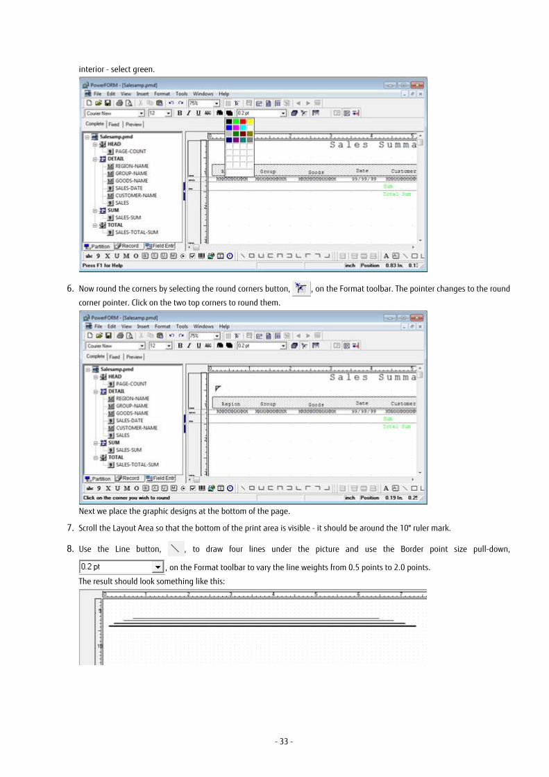
interior - select green.
6. Now round the corners by selecting the round corners button, , on the Format toolbar. The pointer changes to the round
corner pointer. Click on the two top corners to round them.
Next we place the graphic designs at the bottom of the page.
7. Scroll the Layout Area so that the bottom of the print area is visible - it should be around the 10" ruler mark.
8. Use the Line button, , to draw four lines under the picture and use the Border point size pull-down,
, on the Format toolbar to vary the line weights from 0.5 points to 2.0 points.
The result should look something like this:
- 33 -

I. Place ruled lines in the floating partitions.
If you check Figure 3.2, the picture of the final report, you will see there are lines framing the data printed from the DETAIL, SUM, andTOTAL partitions. Because variable amounts of data are printed for each group it would be impossible to pre-print these lines on aform. These lines are therefore placed in the floating partitions.
To do this you use the buttons on the Insert Partition Line toolbar:
If the buttons are disabled (the black lines in the above picture of the toolbar are colored gray), look for the "Show Partition Lines"
button, , on the standard toolbar and click it to turn on the partition lines functionality.
You can draw the lines using whatever shapes you feel are most appropriate. One arrangement is to draw:
- 7 vertical lines in the DETAIL partition
- 1 rectangle and 1 line in the SUM partition
- 1 rectangle and 1 line in the TOTAL partition
A quick way to draw the 7 vertical lines in the DETAIL partition is:
1. Draw the first line to the left of the REGION-NAME field, lining up with the outside of the box surrounding the column titles.Edit the line properties to make sure it is in the correct position with the correct height.
2. Set the Grid (from the menu select View, Grid) ruler divisions to 20 for both Width and Height. (This makes it easier to drag thecopies to the correct positions while giving a reasonably fine granularity.
3. Select 200% for the Zoom factor (This gives you greater control of positions.)
4. Select the vertical line you have drawn and from the Edit menu select Repeat Copy. Set the number of Horizontal copies to 7(the copy numbering includes the item being copied) and "Horizontal Space" to 1" and click OK.PowerFORM makes 6 copies of the vertical line.
5. Select each line in turn and drag them into position between the fields. You will find that some of the lines overlap the fields and that your first click selects the field. Simply keep the pointer in thesame position and click again - PowerFORM selects the line.
When placing the rectangles switch snap-to-grid off. The snap-to-grid function is not sensitive to partition boundaries so can causeyou to draw the rectangle in the wrong partition.
With the lines drawn your partitions should look like this:
J. Confirm the layout of your report by using Preview.
1. If you have turned off the partition list, display it again by selecting "List Frame" from the View menu.
2. Select the Preview tab to change to the Preview view.
3. Notice that the overlay fields are already displayed.
- 34 -

4. In the partition list, click on HEAD, and drag and drop it to onto the Form Layout Area. PowerFORM adds the contents of thispartition to the display.
5. Similarly drag the DETAIL partition onto the Form Layout Area. Because this is a floating partition that can be printed severaltimes, PowerFORM displays a dialog asking how many copies of the partition you want to place in the preview.
6. Enter 15 and click OK.
7. Place one copy of the SUM partition in the Form Layout Area.
8. Make the preview close to an actual print image by dragging several groups of DETAIL and SUM partitions to the Layout Area.
9. PowerFORM displays the partitions in the order they are dropped in the Layout Area.
10. Finally drag the TOTAL partition to the Layout Area.
The result should look like this:
K. Print the preview image.
To confirm how the report will look when printed you can have PowerFORM print the Preview image.
1. From the File menu select Print Preview if you want to check what will be printed.
2. Select Print (or File, Print if you did not preview the print).
L. Save the descriptor
From the File menu select Save.
M. Adapt Sale.cob to use your descriptor
You can adapt the Sale.cob program shown in the next chapter to use the form created in this chapter. The steps to do this are:
1. Create a copy of Sale.cob called Salesamp.cob.
2. Edit Salesamp.cob. Wherever "SALE" is used on its own (i.e. not as part of another word like "SALES-SUM") change it to SALESAMP.
- 35 -

3. Add entries to COBOL85.CBR to give a file assignment for PRTFILE. For example:
[SALESAMP]
PRTFILE=salesamp.prt
"salesamp.prt" would be the printer information file, described in Chapter 4. Although you must have the file assignmentstatement for PRTFILE in COBOL85.CBR, the file salesamp.prt does not have to exist. If PowerFORM cannot find the file, it usesits default behaviors.
4. With these changes you should be able to compile and run Salesamp.cob and create a print file with the test data containedin that program.
- 36 -

Chapter 4 Programming with PowerFORMThis chapter covers all the key points you need to know to write programs that use PowerFORM. It provides information on:
- Coding
- Compiling
- Linking
- Running
- Debugging
- Running on UNIX platforms
and gives a sample program that illustrates the syntax discussed.
4.1 OverviewProgramming with PowerFORM is exactly like working with any other print file. You OPEN and CLOSE the file and WRITE records to it.The main difference from regular print files is that instead of writing one line at a time you write partitions.
There are a few details that you need to understand in programming, compiling, debugging and running programs using PowerFORM.The following sections cover all the information you need to know.
All the coding samples are taken from the program SALE.COB that is in your Sample directory and is listed in Figure 4.1 towards theend of this chapter.
4.2 Coding for PowerFORM
ENVIRONMENT DIVISION
You define the PowerFORM print file in a SELECT statement. The format of the SELECT statement for working with PowerFORMdescriptors is:
SELECT file-name ASSIGN TO file-identifier
ORGANIZATION IS SEQUENTIAL
ACCESS MODE IS SEQUENTIAL
FORMAT IS prt-format-name
GROUP IS prt-group-name
[FILE STATUS IS data-name-1 [data-name-2] ]
Where:
file-name is the name used within the COBOL program for the print file. It is the name used in the FD, OPEN and CLOSE statements.
file-identifier is the name used externally to locate the file. The COBOL runtime expects an environment variable set up to map thisname to a physical file name. The physical file name is that of the printer information file (see below). The print data is written toyour default printer.
prt-format-name must be an 8 character alphanumeric data item defined in the WORKING-STORAGE or LINKAGE section. ThePowerFORM runtime uses the descriptor specified in prt-format-name when your program executes a WRITE statement.
prt-group-name must be an 8 character alphanumeric data item defined in the WORKING-STORAGE or LINKAGE section. ThePowerFORM runtime uses the partition specified in prt-group-name when your program executes a WRITE statement.
data-name-1 and data-name-2 are used for referencing the I-O status as for any other file.
Example:
000140 SELECT PRINT-FILE ASSIGN TO PRTFILE
000150 ORGANIZATION IS SEQUENTIAL
- 37 -

000160 ACCESS MODE IS SEQUENTIAL
000170 FORMAT IS PRT-FORMAT
000180 GROUP IS PRT-GROUP
000190 .
Examples of other code in this chapter will be based on this SELECT statement and will show the key parts (PRINT-FILE, PRTFILE, PRT-FORMAT and PRT-GROUP) being used.
DATA DIVISION
Print File Record Definition
You define the layout for the PowerFORM print file in the FILE SECTION. The format for the FD is:
FD file-name.
COPY form-descriptor-name OF XMDLIB.
Where:
file-name is the internal name defined in the SELECT statement.
form-descriptor-name is the name of your PowerFORM descriptor file. The compiler adds the extension specified in the FORMEXTcompiler option to this name and extracts the record definition from a file of that name in the folder specified in the FORMLIB compileroption.
XMDLIB is a key name of the compiler. It tells the compiler to extract the record definition from the PowerFORM descriptor file.
Example:
000250 FD PRINT-FILE.
000260 COPY SALE OF XMDLIB.
This copies in the record description to be used from the descriptor SALE.PMD. (Assuming the program is compiled with the optionFORMEXT(PMD) .)
Other Data Definitions
The other data items you need to define in your program are:
- item to contain the descriptor name, prt-format-name
- item to contain the partition name, prt-group-name
- item to hold the page count (optional).
prt-format-name and prt-group-name must be defined as 8 character alphanumeric items. For example:
000320 01 PRT-PARAM.
000330 03 PRT-FORMAT PIC X(08) VALUE space.
000340 03 PRT-GROUP PIC X(08) VALUE space.
Your program is responsible for tracking and outputting the page count so, obviously, you need to define an item for that purpose.
PROCEDURE DIVISION
Opening and Closing the Print File
Open and close the PowerFORM print file like any other file. The formats for the statements are:
OPEN OUTPUT file-name
CLOSE file-name
Note that although you ASSIGN the file-name to an external name that in turn is mapped to the printer information file, the printdata is actually output to your default printer.
Examples:
001980 OPEN OUTPUT PRINT-FILE
- 38 -
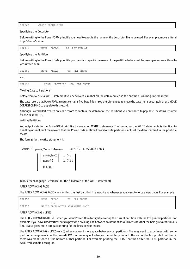
002560 CLOSE PRINT-FILE
Specifying the Descriptor
Before writing to the PowerFORM print file you need to specify the name of the descriptor file to be used. For example, move a literalto prt-format-name.
002040 MOVE "SALE" TO PRT-FORMAT
Specifying the Partition
Before writing to the PowerFORM print file you must also specify the name of the partition to be used. For example, move a literal toprt-format-name.
002050 MOVE "HEAD" TO PRT-GROUP
and
002130 MOVE "DETAIL" TO PRT-GROUP
Moving Data to Partitions
Before you execute a WRITE statement you need to ensure that all the data required in the partition is in the print-file record.
The data record that PowerFORM creates contains five-byte fillers. You therefore need to move the data items separately or use MOVECORRESPONDING to populate this record.
Although PowerFORM creates only one record to contain the data for all the partitions you only need to populate the items requiredfor the next WRITE.
Writing Partitions
You output data to the PowerFORM print file by executing WRITE statements. The format for the WRITE statements is identical tohandling normal print files except that the PowerFORM runtime knows to write partitions, not just the data specified in the print-filerecord.
The format for the write statement is:
(Check the "Language Reference" for the full details of the WRITE statement)
AFTER ADVANCING PAGE
Use AFTER ADVANCING PAGE when writing the first partition in a report and whenever you want to force a new page. For example:
002050 MOVE "HEAD" TO PRT-GROUP
...
002070 WRITE SALE AFTER ADVANCING PAGE
AFTER ADVANCING n LINES
Use AFTER ADVANCING 0 LINES when you want PowerFORM to slightly overlap the current partition with the last printed partition. Forexample if you have used vertical bars to provide a dividing line between columns of data this ensures that the bars give a continuousline. It also gives more compact printing for the lines in your report.
Use AFTER ADVANCING n LINES (n > 0) when you want more space between your partitions. You may need to experiment with somepartition arrangements, as the PowerFORM runtime may not advance the printer pointer to the end of the last printed partition ifthere was blank space at the bottom of that partition. For example printing the DETAIL partition after the HEAD partition in theSALE.PMD sample descriptor.
- 39 -

002130 MOVE "DETAIL" TO PRT-GROUP
...
002240 WRITE SALE AFTER ADVANCING 1 LINE
4.3 Sample Program SourceFigure 4.1 Source of Sample Program "Sale.cob"
000010 IDENTIFICATION DIVISION.
000020 PROGRAM-ID. SALES.
000030 ENVIRONMENT DIVISION.
000040 CONFIGURATION SECTION.
000050 SPECIAL-NAMES.
000060 SYMBOLIC CONSTANT
000070 NORMAL IS " "
000080 .
000090*
000100* Define sequential file for printing
000110*
000120 INPUT-OUTPUT SECTION.
000130 FILE-CONTROL.
000140 SELECT PRINT-FILE ASSIGN TO PRTFILE
000150 ORGANIZATION IS SEQUENTIAL
000160 ACCESS MODE IS SEQUENTIAL
000170 FORMAT IS PRT-FORMAT
000180 GROUP IS PRT-GROUP
000190 .
000200 DATA DIVISION.
000210 FILE SECTION.
000220*
000230* Copy print record from format descriptor
000240*
000250 FD PRINT-FILE.
000260 COPY SALE OF XMDLIB.
01 SALE.
02 FILLER PIC X(5).
02 PAGE-COUNT
PIC 9(3).
02 FILLER PIC X(5).
02 REGION-NAME
PIC X(10).
02 FILLER PIC X(5).
02 GROUP-NAME
PIC X(10).
02 FILLER PIC X(5).
02 GOODS-NAME
PIC X(12).
02 FILLER PIC X(5).
02 SALES-DATE
PIC 9(6).
02 FILLER PIC X(5).
02 CUSTOMER-NAME
PIC X(16).
02 FILLER PIC X(5).
02 SALES PIC 9(13).
02 FILLER PIC X(5).
02 SALES-SUM
PIC 9(13).
02 FILLER PIC X(5).
02 SALES-TOTAL-SUM
PIC 9(13).
02 FILLER PIC X(5).
- 40 -

02 LOGO-AREA
PIC X(8).
000270* ~~~~~name of the format descriptor
000280 WORKING-STORAGE SECTION.
000290*
000300* Control Area
000310*000320 01 PRT-PARAM.
000330 03 PRT-FORMAT PIC X(08) VALUE SPACE.
000340 03 PRT-GROUP PIC X(08) VALUE SPACE.
000350*
000360* Print Data
000370*
000380 01 SAMPLE-DATA.
000390* --- These data being loaded from DB in the actual program. ---
000400 02 DETAIL-LINE.
000410 03 REGION-NAME-DATA-TABLE.
000420 04 PIC X(10) VALUE "New York".
000430 04 PIC X(10) VALUE "Washington".
000440 04 PIC X(10) VALUE "Boston".
000450 04 PIC X(10) VALUE "San Jose".
000460 04 PIC X(10) VALUE "Chicago".
000470 04 PIC X(10) VALUE "Los angels".
000480 04 PIC X(10) VALUE "Sacramento".
000490 04 PIC X(10) VALUE "Honolulu".
000500 04 PIC X(10) VALUE "Tokyo".
000510 04 PIC X(10) VALUE "HongKong".
000520 03 REDEFINES REGION-NAME-DATA-TABLE.
000530 04 REGION-NAME-DATA PIC X(10) OCCURS 10.
000540 03 GROUP-NAME-TABLE.
000550 04 PIC X(10) VALUE "GOLF".
000560 04 PIC X(10) VALUE "FOOTBALL".
000570 04 PIC X(10) VALUE "SKI".
000580 04 PIC X(10) VALUE "TENNIS".
000590 03 REDEFINES GROUP-NAME-TABLE.
000600 04 G-NAME PIC X(10) OCCURS 4.
000610 03 GOODS-NAME-DATA-TABLE.
000620 04 PIC X(12) VALUE "Shoes".
000630 04 PIC X(12) VALUE "Bag".
000640 04 PIC X(12) VALUE "Wear".
000650 04 PIC X(12) VALUE "Ball".
000660 04 PIC X(12) VALUE "Shoes".
000670 04 PIC X(12) VALUE "Wear".
000680 04 PIC X(12) VALUE "Club Set".
000690 04 PIC X(12) VALUE "Bag".
000700 04 PIC X(12) VALUE "Ball".
000710 04 PIC X(12) VALUE "Wear".
000720 04 PIC X(12) VALUE "Shoes".
000730 04 PIC X(12) VALUE "Club Set".
000740 04 PIC X(12) VALUE "Shoes".
000750 04 PIC X(12) VALUE "Ball".
000760 04 PIC X(12) VALUE "Bag".
000770 04 PIC X(12) VALUE "Club Set".
000780 03 REDEFINES GOODS-NAME-DATA-TABLE.
000790 04 GOODS-NAME-DATA PIC X(12) OCCURS 16.000800 03 DATE-DATA-TABLE.
000810 04 PIC 9(6) VALUE 200196.
000820 04 PIC 9(6) VALUE 200296.
000830 04 PIC 9(6) VALUE 200296.
000840 04 PIC 9(6) VALUE 200396.
000850 04 PIC 9(6) VALUE 200396.
000860 04 PIC 9(6) VALUE 200496.
000870 04 PIC 9(6) VALUE 200596.
000880 04 PIC 9(6) VALUE 200696.
000890 04 PIC 9(6) VALUE 200696.
- 41 -

000900 04 PIC 9(6) VALUE 200696.
000910 04 PIC 9(6) VALUE 200796.
000920 04 PIC 9(6) VALUE 200896.
000930 04 PIC 9(6) VALUE 200996.
000940 04 PIC 9(6) VALUE 201196.
000950 04 PIC 9(6) VALUE 201296.
000960 04 PIC 9(6) VALUE 201296.
000970 03 REDEFINES DATE-DATA-TABLE.
000980 04 DATE-DATA PIC 9(6) OCCURS 16.
000990 03 CUSTOMER-NAME-DATA-TABLE.
001000 04 PIC X(16) VALUE "Fujitsu Green Inc.".
001010 04 PIC X(16) VALUE "Fujitsu Blue Co.,Ltd.".
001020 04 PIC X(16) VALUE "Fujitsu Cyan Trading".
001030 04 PIC X(16) VALUE "Fujitsu White Inc.".
001040 04 PIC X(16) VALUE "Fujitsu Yellow Inc.".
001050 04 PIC X(16) VALUE "Fujitsu Black Trading".
001060 04 PIC X(16) VALUE "Fujitsu Brown Co.,Ltd.".
001070 04 PIC X(16) VALUE "Fujitsu Gray Trading".
001080 04 PIC X(16) VALUE "Fujitsu Pink Inc.".
001090 04 PIC X(16) VALUE "Fujitsu Light Blue Inc.".
001100 04 PIC X(16) VALUE "Fujitsu Red Business".
001110 04 PIC X(16) VALUE "Fujitsu Magenta Co.,Ltd".
001120 04 PIC X(16) VALUE "Fujitsu Purple Inc.".
001130 04 PIC X(16) VALUE "Fujitsu Silver Business".
001140 04 PIC X(16) VALUE "Fujitsu Orange Trading".
001150 04 PIC X(16) VALUE "Fujitsu Golden Inc.".
001160 03 REDEFINES CUSTOMER-NAME-DATA-TABLE.
001170 04 CUSTOMER-NAME-DATA PIC X(16) OCCURS 16.
001180 03 SALES-DATA-TABLE.
001190 04 PIC 9(13) VALUE 200000.
001200 04 PIC 9(13) VALUE 600000.
001210 04 PIC 9(13) VALUE 500000.
001220 04 PIC 9(13) VALUE 5000.
001230 04 PIC 9(13) VALUE 200000.
001240 04 PIC 9(13) VALUE 500000.
001250 04 PIC 9(13) VALUE 1800000.
001260 04 PIC 9(13) VALUE 600000.
001270 04 PIC 9(13) VALUE 5000.
001280 04 PIC 9(13) VALUE 500000.
001290 04 PIC 9(13) VALUE 200000.
001300 04 PIC 9(13) VALUE 1800000.
001310 04 PIC 9(13) VALUE 200000.
001320 04 PIC 9(13) VALUE 5000.
001330 04 PIC 9(13) VALUE 600000.
001340 04 PIC 9(13) VALUE 1800000.
001350 03 REDEFINES SALES-DATA-TABLE.
001360 04 SALES-DATA PIC 9(13) OCCURS 16.
001370 02 SUM-LINE.
001380 03 SALES-SUM PIC 9(13) VALUE 0.
001390 02 TOTAL-SUM-LINE.
001400 03 SALES-TOTAL-SUM PIC 9(13) VALUE 0.
001410 02 WORK-TABLE.
001420 03 GROUP-1-TABLE.
001430 04 PIC 9(2) VALUE 16.
001440 04 PIC 9(2) VALUE 12.
001450 04 PIC 9(2) VALUE 5.
001460 04 PIC 9(2) VALUE 9.
001470 04 PIC 9(2) VALUE 15.
001480 04 PIC 9(2) VALUE 8.
001490 04 PIC 9(2) VALUE 7.
001500 04 PIC 9(2) VALUE 5.
001510 04 PIC 9(2) VALUE 13.
001520 04 PIC 9(2) VALUE 10.
- 42 -

001530 03 GROUP-2-TABLE.
001540 04 PIC 9(2) VALUE 7.
001550 04 PIC 9(2) VALUE 8.
001560 04 PIC 9(2) VALUE 9.
001570 04 PIC 9(2) VALUE 14.
001580 04 PIC 9(2) VALUE 5.
001590 04 PIC 9(2) VALUE 9.
001600 04 PIC 9(2) VALUE 10.
001610 04 PIC 9(2) VALUE 7.
001620 04 PIC 9(2) VALUE 5.
001630 04 PIC 9(2) VALUE 13.
001640 03 GROUP-3-TABLE.
001650 04 PIC 9(2) VALUE 9.
001660 04 PIC 9(2) VALUE 6.
001670 04 PIC 9(2) VALUE 9.
001680 04 PIC 9(2) VALUE 12.
001690 04 PIC 9(2) VALUE 8.
001700 04 PIC 9(2) VALUE 13.
001710 04 PIC 9(2) VALUE 5.
001720 04 PIC 9(2) VALUE 8.
001730 04 PIC 9(2) VALUE 11.
001740 04 PIC 9(2) VALUE 8.
001750 03 GROUP-4-TABLE.
001760 04 PIC 9(2) VALUE 10.
001770 04 PIC 9(2) VALUE 11.
001780 04 PIC 9(2) VALUE 9.
001790 04 PIC 9(2) VALUE 13.
001800 04 PIC 9(2) VALUE 7.
001810 04 PIC 9(2) VALUE 10.
001820 04 PIC 9(2) VALUE 12.
001830 04 PIC 9(2) VALUE 6.
001840 04 PIC 9(2) VALUE 4.
001850 04 PIC 9(2) VALUE 7.
001860 02 REDEFINES WORK-TABLE.
001870 03 OCCURS 4.
001880 04 GROUP-N PIC 9(2) OCCURS 10.
001890* Counters
001900 77 CNTI PIC 9(2) BINARY.
001910 77 CNTJ PIC 9(2) BINARY.
001920 77 PAGEN PIC 9(3) BINARY.
001930*
001940******************************************************************
001950 PROCEDURE DIVISION.
001960*
001970* Open Print File
001980 OPEN OUTPUT PRINT-FILE
001990 INITIALIZE SALE
002000 .
002010* Header
002020* (fixed positional partition : HEAD)
002030 PERFORM VARYING PAGEN FROM 1 BY 1 UNTIL PAGEN > 2
002040 MOVE "SALE" TO PRT-FORMAT
002050 MOVE "HEAD" TO PRT-GROUP
002060 MOVE PAGEN TO PAGE-COUNT OF SALE
002070 WRITE SALE AFTER ADVANCING PAGE
002080* ~~~~~~~~~~~~~~~~~~~~ form feed
002090 PERFORM VARYING CNTI FROM 1 BY 1 UNTIL CNTI > 4
002100* Detail line printing
002110* (floating positional partition : DETAIL)
002120* Set sample data
002130 MOVE "DETAIL" TO PRT-GROUP
002140 PERFORM VARYING CNTJ FROM 1 BY 1 UNTIL CNTJ > GROUP-N(CNTI PAGEN)
002150 MOVE GOODS-NAME-DATA(CNTJ) TO GOODS-NAME OF SALE
- 43 -

002160 MOVE DATE-DATA(CNTJ) TO SALES-DATE OF SALE
002170 MOVE CUSTOMER-NAME-DATA(CNTJ) TO CUSTOMER-NAME OF SALE
002180 MOVE SALES-DATA(CNTJ) TO SALES OF SALE
002190 ADD SALES-DATA(CNTJ) TO SALES-SUM OF SUM-LINE
002200 IF CNTJ = 1 THEN
002210 MOVE REGION-NAME-DATA(PAGEN) TO REGION-NAME OF SALE
002220 MOVE G-NAME(CNTI) TO GROUP-NAME OF SALE
002240 WRITE SALE AFTER ADVANCING 1 LINE
002250* ~~~~~~~~~~~~~~~~~~~~~ form feed
002300 MOVE SPACE TO REGION-NAME OF SALE
002310 MOVE SPACE TO GROUP-NAME OF SALE
002320 ELSE
002330 WRITE SALE AFTER ADVANCING 1 LINE
002340* ~~~~~~~~~~~~~~~~~~~~ no form feed
002350 END-IF
002360 END-PERFORM
002370* Sum printing
002380* (floating positional partition : SUM)
002390 MOVE "SUM" TO PRT-GROUP
002400 MOVE CORR SUM-LINE OF SAMPLE-DATA TO SALE
002410 WRITE SALE AFTER ADVANCING 1 LINE
002420 ADD SALES-SUM OF SUM-LINE TO SALES-TOTAL-SUM OF TOTAL-SUM-LINE
002430 MOVE 0 TO SALES-SUM OF SUM-LINE
002440 END-PERFORM
002450* Total sum printing
002460* (floating positional partition : TOTAL)
002470 MOVE "TOTAL" TO PRT-GROUP
002480 MOVE "LOGO.BMP" TO LOGO-AREA OF SALE
002490 MOVE "B" TO EDIT-MODE OF LOGO-AREA OF SALE
002500 MOVE CORR TOTAL-SUM-LINE OF SAMPLE-DATA TO SALE
002510 WRITE SALE AFTER ADVANCING 1 LINE
002520 END-PERFORM
002530******************************************************************
002540 CLOSE PRINT-FILE
002550 STOP RUN
002560 .
002570 END PROGRAM SALES.
4.4 Building and Running with PowerFORM
Compiling
When the compiler encounters a "COPY descriptor-name OF XMDLIB" statement it looks for the file "descriptor-name.PMD" and picksup the COPY library from there. It looks in the folder containing the COBOL source unless you specify the following compiler option:
FORMLIB(folder-name-1[;folder-name-2][...])
If you specify this option the compiler looks for the file in folder-name-1 then, if specified, folder-name-2 etc.
If you chose to override PowerFORM's default extension for descriptor files (.PMD) you need to set the compiler option:
FORMEXT(XXX)
Where XXX is the extension you used. This tells the compiler that the extension being used for PowerFORM descriptor files is .XXX. Bydefault the compiler looks for extensions .PMD and .SMD (the latter was used in the earlier FORM product).
Linking
There are no special requirements for linking programs that use PowerFORM print files.
- 44 -

Running
The Printer Information File
The PowerFORM run-time system accepts printer and run-time behavior information from a file called the printer information file. Forexample, you can specify that a dialog should be displayed when the report is printing or the paper supply that should be used. Figure4.2 shows an example of the printer information file.
Figure 4.2. A Sample Printer Information File
*
* Printer Information File
*
PRTDIALG Y * Print Dialog : YES
PRTID "Sales Summary" * Title displayed by Print Manager
FORMKIND C * Kind of form : cut paper
See the PowerFORM runtime on-line help (pformapi.hlp) for full details of the printer information file parameters. Note thatPowerFORM V2 no longer requires the font number mapping as the font names are defined within the PowerFORM descriptor file.
By using different Printer Information Files you can run the same PowerFORM application in different environments.
The file-identifier in the ASSIGN clause needs to be mapped to the name of a printer information file. See the next topic, "RuntimeEnvironment Variables", for details.
If a file name is not provided the COBOL run-time system will give an error. However, if a file of the given name does not exist, thePowerFORM run-time system will still execute using its defaults.
Note that the COBOL User Guide describes a file called the "print information file" - this is a different file for print files that do not havethe "FORMAT" clause in the ASSIGN statement.
Runtime Environment Variables
You need to include the following mapping in your runtime environment variables:
file-identifier=printer-information-file-name
Where:
file-identifier is the name defined in the ASSIGN TO phrase of the SELECT statement
printer-information-file-name is the name of the printer information file.
For example with a printer information file called "SALE.PRT" and an ASSIGN TO name of "PRTFILE" you need the following in yourenvironment variables:
PRTFILE=SALE.PRT
The environment variables for your program can either be specified in the COBOL85.CBR file or at run time if the environment variable"@EnvSetWindow" is set to "USE".
Default Printer
The PowerFORM runtime writes the completed report to your system's default printer.
Debugging
You can debug PowerFORM applications using the standard COBOL debugger.
If your form descriptors are stored in a different folder from the main program, or if you have used an extension other than .PMD foryour form descriptors, make sure you specify the following information on the Descriptor tab of the Start Debugging dialog box:
- Screen form descriptor folder. This is the folder that contains your form descriptor files. You only need to specify this folder if it isdifferent from the folder containing the main program. (This can also be specified in the /M option when invoking the debuggerfrom the command line.)
- Screen form descriptor extension. Set this to the extension you used. (This can also be specified in the /E option when invokingthe debugger from the command line.)
- 45 -

4.5 UNIX ConsiderationsYou can develop PowerFORM reports in the Windows environment that are executed in the UNIX environment. When you do this takenote of the following Printer Information File points:
- The supported fonts are likely to be different so you need to edit the font list.
- The key word PRTDEV is required. If it is omitted the runtime displays an error message when your program opens the print file.PRTDEV specifies the printer model name of the printer device.
- The overlay descriptor must be stored in a directory called "Kol5". The keyword OVLPDIR specifies the parent directory of the "Kol5"directory.
- 46 -

Chapter 5 Using PowerFORMThis chapter provides guidelines on using some detailed features of PowerFORM and answers some common questions relating tousing PowerFORM.
5.1 Populating Wizard Data Item CategoriesWhen you use the Wizard to create a new form one of the windows lets you populate your partitions with data items. The data itemsare selected from a number of categories. PowerFORM provides a number of useful categories and data items but you also need tocreate and populate your own categories.
The PowerFORM Wizard reads the categories and data items from a file called pformwiz.ini stored in the PowerFORM folder. You canadd your own categories and edit the existing categories. To do this:
1. Exit PowerFORM.
2. Load pformwiz.ini into a text editor, such as Notepad.
3. To create a new category, insert your category name into the list under the [GROUP] tag. Put your new category where youwould like it to appear in the drop down list in the Wizard window and renumber the other groups.
The format for the category lines is:
category-name = n
Where:
category-name is the name you want to use for the list of data items
n is a number reserved for future use (but is best made to reflect the order of the categories).
For example, to insert the category "My data" at the head of the list, edit the [GROUP] items to read:
[GROUP]
My data=1
Code=2
Number=3
Name=4
Date&Time=5
Money=6
Address=7
Etc.=8
Sample=9
Note: Do not use tabs in the pformwiz.ini file. Separate items by spaces.
4. Add your data item entries to pformwiz.ini. The format for data item lists is:
[category-name]
numeric-name = Numeric, num-length, decimal-digits
text-name = Text, text-length
Block text-name = RectText, Block text-length
UCS2-name = JText, UCS2-length
Block UCS2-name = RectJText, Block USC2-length
Mixed text-name = MText, Mixed text-length
Block Mixed text-name = RectMText, Block Mixed text-length
Radio button-name = Radio, valu for Selected State
Check box-name = Check, valu for Selected State
bitmap-name = Bitmap, Bitmap, height, width
barcode-name = Barcode, height, width
...
Where:
category-name is the string you entered under the [GROUP] tag
- 47 -

"Numeric", "Text", "RectText", "JText", "RectJText", "MText", "RectMText", "Radio", "Check", "Bitmap", and "Barcode" are keywordsused to identify the field type.
numeric-name is the name you wish to give a numeric field
num-length is the total number of digits (including the decimal digits) in the field, in the range 1 to 18
decimal-digits is the number of digits after the decimal point for the numeric field, in the range 0 to 18
text-name is the name you wish to give a text field
text-length is the text field length in bytes, in the range 1 to 256
Block text-name is the name you wish to give a block text field
Block text-length is the block text field length in bytes, in the range 1 to 256
UCS2-name is the name you wish to give a USC2 field
UCS2-length is the UCS2 field length in bytes, in the range 2 to 256
Block UCS2-name is the name you wish to give a block UCS2 field
Block UCS2-length is the block UCS2 field length in bytes, in the range 2 to 256
Mixed text-name is the name you wish to give a mixed text field
Mixed text -length is the mixed text field length in bytes, in the range 3 to 256
Block Mixed text-name is the name you wish to give a block mixed field
Block Mixed text-length is the block mixed field length in bytes, in the range 1 to 256
Radio button-name is the name you wish to give a radio button field
Check box-name is the name you wish to give a check box field
valu for Selected State is the Selected State with a value of up to 255 characters. At least one character is needed.
bitmap-name is the name you wish to give a bitmap field
barcode-name is the name you wish to give a barcode field
height is the height occupied by the bitmap or barcode, expressed in lines, in the range 1 to 12 (6 lines per inch)
width is the width occupied by the bitmap or barcode, expressed in columns, in the range 1 to 20 (12 columns per inch)
You can insert the items in any order. The Wizard displays them in the order entered.
The list is terminated by the next category tag or the end of the file.
For example, to create a category "My data" consisting of three items:
- a numeric field with COBOL description:
03 MY-DATA-NUMBER PIC 9(5)V99.
- a text field with COBOL description:
03 MY-DATA-TEXT PIC X(15).
- and a field called MY-BITMAP to contain a bitmap,
you would add the following to the pformwiz.ini file:
[My data]
MY-DATA-NUMBER = Numeric, 7, 2
MY-DATA-TEXT = Text, 15
MY-BITMAP = Bitmap, Bitmap, 6, 12
Note: Do not use tabs in the pformwiz.ini file. Separate items by spaces.
5. Save the pformwiz.ini file and restart PowerFORM. Bring up the wizard and check that your entries have been added to thecategory list.
6. If there are problems with your additions to the pformwiz.ini file the Wizard displays error messages.
- 48 -

5.2 Editing Wizard Data ItemsTo edit an item's properties within the PowerFORM Wizard select the item and click on the Property button.
5.3 Choosing the Default Date Format
When you insert a date field using either Insert, Date or the button on the Insert Field toolbar, PowerFORM displays a default
date format such as MM.DD.YYYY. Your country, or company, may use a different format most of the time. To change the defaultformat:
1. From the Tools menu select "Fields Default Value". This displays the "Default Values for Fields" dialog box.
2. Select the String tab.
3. In the "Date Field" group box you can select you would like from the "String Sample" drop down list. Alternatively you can enter your own string that includes normal characters with the key strings DD, MM, MMM, MMMM, YY,YYYY. For example, to make MM/DD/YY the default enter "MM/DD/YY" in the String field.
4. Click OK. Your string becomes the default for future date insertions.
5.4 Selecting Borders and Shading Colors
For graphic objects such as rectangles, ellipses, and overlay characters you can use the Overlay Color button, , on the Format
toolbar.
To select the border color of an object:
1. Select the object.
2. Click the button.
3. Move the mouse over the color you wish to select and click the left mouse button.
To select the shading color of an object:
1. Select the object.
2. Click the button.
3. Move the mouse over the color you wish to select and click the right mouse button.
If the shading color does not appear, select the Patterns button, , and select a shading from the palette of patterns offered.
Note that the first 18 patterns include a border, the last 17 patterns do not include a border. Clicking on the pattern, and notreleasing the mouse button, displays the shading density percentage.
5.5 Configuring the Color Palettes
The palettes shown by the and buttons, and in the Color drop down lists, contain 16 system colors and 16 custom colors.
To change the custom colors select either "Field Color Palette" or "Overlay Color Palette" from the Format menu. This brings up a dialogdisplaying the 16 configurable colors.
To change one of these colors:
1. Click on that color (or on the white box below a number if no custom colors have been configured).PowerFORM displays the Color selection dialog with 48 basic colors and 16 custom colors (which may all be white if no customcolors have been set up).
- 49 -

2. Select a basic color or a custom color and click OK.
To add or change one of the custom colors:
3. Select the custom color box by clicking on it.
4. Click on the "Define Custom Colors >>" button. This widens the Color dialog, displaying a rainbow box, luminosity scale and editable fields for hue, saturation, luminosity, red,green and blue values.
5. Select the color you want by doing one of the following:- Drag the pointer in the rainbow box and slide the luminosity pointer (if the pointer is at the top, i.e. luminosity is 240, clickbelow the slider to start it sliding). - Directly edit the Hue, Saturation and Luminosity values.- Directly edit the Red, Green, and Blue values.The selected color is shown in the box labeled "Color|Solid".
6. Click the "Add to Custom Colors" button.The selected Custom Color box is updated with your configured color.
7. You can repeat steps 5 and 6 to set up more of the Custom Color boxes. Each time you click "Add to Custom Colors", the nextCustom Color box is updated.
Note: The Custom Colors shown in the Color dialog are NOT the colors in the Field or Overlay Color Palettes. They are colors fromwhich you can select the field or overlay palette colors.
5.6 Clearing the Preview Layout AreaTo clear the preview layout area, right click in the layout area to display the pop-up menu. Select "Hide All Partitions" from the pop-up menu. This clears all displayed partitions from the preview layout area.
5.7 Repeating Fields and ObjectsWhen designing forms you often have repeating patterns of data or design elements (such as lines). PowerFORM V2 provides twoways of creating repeating patterns in horizontal and vertical directions: the "Repeat Copy" function and Repeat property for fields.
Repeat Copy
Repeat Copy, on the Edit and pop-up menus, lets you make several copies of one or more selected objects. The copies are spacedhorizontally or vertically or both, according to the spacing you specify in the Repeat Copy dialog.
Each new object is given a new name - numbering left to right, top to bottom or top to bottom, left to right depending on whetheryou selected the Direction to be Right or Down.
After the repeat copy has been performed, the fields are not linked to each other. Their names are similar but may not be consecutivelynumbered if other objects in the form have names of the same format using intervening numbers.
Repeating Occurrence of a Field
You can define text, numeric and bar code fields to be repeating fields.
To do this:
1. Select the field and display the Properties dialog (right click on the field and select "Properties" from the pop-up menu).
2. Select the "Record Properties" tab.
3. Check the "Repeat" checkbox.The group boxes in the lower half of the tab are enabled.
4. Select the number of horizontal and vertical occurrences of the field, and set the total number of occurrences if not equal tothe product of the vertical and horizontal occurrences.
5. Edit the vertical and horizontal spacing.
- 50 -
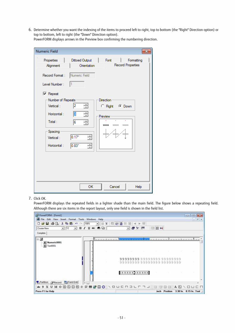
6. Determine whether you want the indexing of the items to proceed left to right, top to bottom (the "Right" Direction option) ortop to bottom, left to right (the "Down" Direction option).PowerFORM displays arrows in the Preview box confirming the numbering direction.
7. Click OK.PowerFORM displays the repeated fields in a lighter shade than the main field. The figure below shows a repeating field.Although there are six items in the report layout, only one field is shown in the field list.
- 51 -

Unlike repeat copies, the repeated fields are strongly linked to the main field. You cannot edit the repeated fields, and if you movethe main field in the layout, the other fields move with it.
You reference the repetitions in your COBOL program by using subscripts. For example, to set the third item in the above array to 55you would code:
MOVE 55 TO REPEATING(3)
5.8 Partition and Overlay LinesIn V1, you could only draw lines in the form overlay - the part that forms the background on which partitions are printed. If you wantedto draw lines or rectangles in partitions, you had to use the underscore and vertical bar characters.
In V2, you can now draw lines and rectangles in partitions using the buttons on the Insert Partition Line toolbar:
Simply select the type of line or rectangle you want to draw and click and drag to create it in the layout area.
Note:
1. "Show Partition Lines" must be selected for the buttons to be enabled and the lines to be visible. "Show Partition Lines" can be
selected on the View menu, or using the "Show Partition Lines" button, , on the Standard toolbar.
2. Partition line drawing will not work if you attempt to draw outside a partition.
5.9 Defining Record LayoutsIn PowerFORM V2 you have the ability to define the layout of the record that is copied into your COBOL program.
To do this you select the Record Name List tab, , at the base of the field list pane. PowerFORM displays the fields in
the order they will appear in the record.
In the Record Name List view you can:
- Drag and drop items to change their order in the record.
- Insert group items - use the Group function on the pop-up menu or select Insert, Group Field from the PowerFORM menu.
- Insert filler items - use the Record function on the pop-up menu or select Insert, Record from the PowerFORM menu.
- Change the level numbers - use the Change Level function on the pop-up menu or select Edit, Change Level from the PowerFORMmenu.
- Rename the fields - click on the name and enter your new name.
5.10 Using Common RecordsPowerFORM V6 lets you establish multiple fields that share a common data item in the record layout. Numeric fields and text fieldscan share common data.
You establish that the fields are common data fields when you create them.
You can create common data fields using one of the following operations:
- Select an item in the Record Name List (Record Name List tab, , selected in the field list pane), drag it and drop
it onto the form layout. PowerFORM creates a field that shares the same data item.
- Select a field in the form layout area and select Edit, Add Common Record from the PowerFORM menu. PowerFORM creates a fieldthat uses the same data item as the selected field.
- 52 -

When you have defined common record fields, you can select all the common records by double clicking on the data item in the recordname list.
Editing Common Record Fields
PowerFORM allows you to define different display formats for common record fields, as long as those formats are compatible. Fieldsare compatible if they have:
- Identical field names
- Identical item lengths
- Identical decimal place settings
- Identical 'Display "+" Positive' settings
For example, fields with editing styles Z9:Z9:Z9 and 999999 are compatible, whereas fields with editing styles Z9:Z9:Z9 and 999999with decimal places set to 2 are not compatible.
PowerFORM ensures that common data record fields are consistent. It does this by:
- Ensuring that if any of the above attributes are changed for one field in a common data group, they are changed for all items inthe group. If necessary, the editing format will also be changed to maintain compatibility. For example, if you change the decimalplaces on a 999999 field, the other common data fields may be changed to 999999 format.
- Deleting all common data record fields if the common data item (in the record name list) is deleted.
- Allowing deletion of common data record fields until there is only one common data record field left, in which case the field is nolonger considered to be a common data record field.
5.11 Using the Wizard Label PatternsThe settings in the Wizard for this pattern is self-explanatory.
When the fields are displayed in PowerFORM, note that PowerFORM only shows you the area inside the print margins; it does notshow you the whole page. Consequently, PowerFORM displays the labels and fields aligned with the top and left edges of the layoutarea. Expect to perform a few trial generate and test print runs before creating your final version.
The Wizard creates repeating groups for the duplicated areas in this pattern. You can edit the properties of the first item in the groupand the other items in the group conform to those properties. In your COBOL program you populate the data using subscripted dataitems.
5.12 PowerFORM Questions
Why do Fonts Appear Not to Change?
Sometimes when you select a new font for a field PowerFORM does not reflect that change in the layout area. If the field is selectedthe Format toolbar displays the font you selected, but the layout area shows the field in the default font.
This is because PowerFORM lets you create forms using fonts not currently available on your machine.
You can configure the font used in place of non-available fonts by selecting PowerFORM Options from the Tools menu and changingthe Alternative Font.
How do I Position and Size Fixed Partitions?
Because the All view shows all the partitions it is tempting to think that it is showing all the partitions in their expected positions.With this misunderstanding you might drag the borders between the partitions expecting to alter the position of the fixed partitions.However, All view shows the partitions stacked one under the other in the order they are defined in the partition list. It does not showfixed partitions in their true positions.
To size and position fixed partitions it is best to switch to the Fix view. This shows the partitions in their true positions. In Fix view youcan reposition the partition by dragging the partition label in the vertical ruler, and alter the height by dragging the bottom dividerline.
- 53 -

Alternatively you can edit the partitions' position and height in the Partition Properties dialog box. To do this:
1. Select the partition in the partition list.
2. Right click to bring up the pop-up menu.
3. Select Properties from the pop-up menu.
4. Enter the desired values for Position and Height.
5. Click OK.
- 54 -

Index[Special characters]
.OVD files................................................................................7
.PMD files............................................................................... 7
[A]AFTER ADVANCING................................................................39All view.................................................................................18anchor symbol......................................................................16
[B]borders.................................................................................49
[C]clear Preview........................................................................ 50CLOSE statement.................................................................. 38coding.................................................................................. 37color palette......................................................................... 49common data.......................................................................52common records..............................................................52,53compiling............................................................................. 44control menu........................................................................15copy..................................................................................... 50custom colors....................................................................... 49
[D]DATA DIVISION......................................................................38date field..............................................................................49debugging............................................................................45default printer...................................................................... 45descriptor file.................................................................... 7,39detail lines............................................................................. 8development process.......................................................... 5,6
[E]ENVIRONMENT DIVISION.......................................................37Environments supported........................................................ 2execution process...................................................................5
[F]FD statement....................................................................... 38field color............................................................................. 12field list........................................................................... 51,52fields............................................................................... 50,52FILE SECTION........................................................................ 38filler......................................................................................52fixed partitions.......................................................................8fixed report............................................................................ 9Fix view................................................................................ 18floating partitions.................................................................. 8fonts................................................................................12,53form....................................................................................... 7FORMEXT option...................................................................44Form Layout Area................................................................. 11FORMLIB option................................................................... 44
[G]group item........................................................................... 52
[H]Head/Body/Tail report............................................................ 9header....................................................................................8horizontal repeat..................................................................50
[I]interface...............................................................................11
[L]level numbers...................................................................... 52lifebelt symbol..................................................................... 16lines..................................................................................... 52linking..................................................................................44
[M]menu bar............................................................................. 15Multiple Parts report.............................................................. 9
[O]OPEN statement...................................................................38overlay color...............................................................12,32,49overlay files............................................................................ 7OVLPDIR............................................................................... 46
[P]partition.......................................................................... 16,18partition lines..................................................................34,52Partition Name List.............................................................. 11partitions......................................................................8,39,53patterns...........................................................................12,32pformwiz.ini......................................................................... 47point size..............................................................................12pop-up menus......................................................................16PowerFORM..................................................................7,11,37PowerFORM V2....................................................................... 2Preview...................................................................... 18,34,50print..................................................................................... 35printer.................................................................................. 45printer information file.........................................................45print file............................................................................... 37PROCEDURE DIVISION........................................................... 38programming....................................................................... 37properties.............................................................................12PRTDEV.................................................................................46
[R]record layout........................................................................ 52Record Name List................................................................. 11rectangles....................................................................... 32,53repeat.................................................................................. 50repeating........................................................................ 50,53
- 55 -

report patterns....................................................................... 9reports..................................................................................18round corners.................................................................. 12,33rulers....................................................................................16runtime.................................................................................. 7runtime environment variables............................................45
[S]selecting...............................................................................27SELECT statement.................................................................37shading................................................................................ 49status bar............................................................................. 18sum lines................................................................................8supported environments........................................................ 2
[T]Tack Seal report......................................................................9target printer........................................................................45toolbars............................................................12,13,14,17,52tooltips.................................................................................11
[U]UNIX..................................................................................6,46
[V]vertical repeat...................................................................... 50views.................................................................................... 18
[W]Wizard............................................................................... 9,47WRITE statement..................................................................39writing print files..................................................................37
[X]XMDLIB........................................................................... 38,44
- 56 -