Embed Size (px)
Citation preview

Orkustofnun, Grensasvegur 9, Reports 2015 IS-108 Reykjavik, Iceland Number 28
607
GEOTHERMAL WELL DESIGN USING THE NEW 2015 NEW ZEALAND STANDARD AND 1991 STANDARD:
A CASE OF MW-20A IN MENENGAI, NAKURU COUNTY, KENYA
Anthony Ng’ang’a Ngigi Geothermal Development Company - GDC
P.O. Box 100746-00101, Nairobi KENYA
ABSTRACT The design of geothermal wells is an important task in well construction, as this allows the effective conveyance of geothermal fluids from deep depths to the surface for utilization. The New Zealand design code NZS 2403:1991 has been used for the last two decades to design geothermal wells, but in 2015 it was replaced by a new design code NZS 2403:2015. This report presents the design of a geothermal well using the two design codes for comparison purposes. The well was designed using exact reservoir conditions in Menengai geothermal field in Kenya, using MW-20A as a reference well. After determining the reservoir pressure, the minimum casing depth for the different casing strings was determined from the codes. In addition, the design premises were established and it was found that the worst case for design was when the well was considered to be filled with steam from bottom to surface. Design calculations were carried out given this condition using the two codes and the best casing strings were determined. The design computations showed that a 20” 94 lb/ft casing, 13⅜” 54.5 lb/ft casing and 9⅝” 47 lb/ft casing were adequate to be run in hole for surface, anchor and production strings respectively. Further calculations showed that the weight of the production casing could be reduced to 36 lb/ft and still be within the minimum design factors, but to account for corrosion during the life of the well, the 47 lb/ft production casing was selected. Due to high stresses when the production casing rises into the wellhead, the weight of the upper two joints of the anchor casing string was changed to 72 lb/ft from 54.5 lb/ft. Several design considerations have changed between the codes, that include the following: The 2015 code gave deep minimum casing depths compared to the 1991 code. Temperature reduction factors for yield were reduced in the 2015 code when checked against the 1991 code. Minimum design factors for thermal expansion of anchor casing into wellhead and compressive stress in liners were reduced to 1.4 and 1.0 in the 2015 code from 1.5 and 1.2 in the 1991 code, respectively. The 2015 code considers fracture pressure for maximum pressure boundary while determining minimum casing depth while the 1991 code considers the overburden. The 1991 code does not allow the thermal expansion of the casing to exceed minimum yield, while the 2015 code acknowledges the use of strain based design in such cases. It is recommended that to avoid the introduction of tensional stresses into the well, cold fluids should not be pumped into a hot well.

Ngigi 608 Report 28
1. INTRODUCTION Hole (2008a) describes the geothermal well design process as a think through process where the engineer has to consider; the purpose and objective of the well, conditions likely to be encountered downhole during drilling, identification of material and equipment required, and safe drilling procedures that will ensure successful well completion and thereafter a satisfactory design life of the well. A sound design is required to achieve a satisfactory well drilling process, and to obtain the integrity and desired life of the well. Part of the design is the selection of casing depths and specification of the material weights and connections. The course taken in casing design and determining the right specification embraces the knowledge of the prerequisite services of the casings, proper setting depths and scrutinizing potential modes of failure. Typically, geothermal wells are constructed from several concentric steel casings, with cement in the annulus between the casing walls and the hole. It is essential to achieve structural integrity of the casings, especially for high temperature wells which are normally characterised by high temperature and pressure. Failure of casings in such wells may lead to reduced energy output from the well or making it difficult to operate the well and in worst cases cause unsafe conditions outside the well such as blow outs (Kaldal et al., 2013). The New Zealand 1991 code of practice for deep geothermal wells (NZS 2403:1991) has been used as a guideline for designing geothermal wells since it was released. Since the inception of this design code, many deep geothermal wells have been drilled worldwide providing additional design information and challenges necessitating the revision of the code. Therefore, the NZS 2403:1991 code has been undergoing review and in 2015 it was replaced by NZS 2403:2015 code of practice for deep geothermal wells. The NZS 2403:2015 code has incorporated the knowledge and experiences gained by geothermal drilling experts from years of designing geothermal wells. This study will use the new and old New Zealand code of practice (NZS 2403:2015) and (NZS 2403:1991) to design a 2000 m deep well for the reservoir conditions already identified at the Menengai geothermal area in Kenya. The reference high temperature geothermal well MW-20A, is a directional well already drilled in the Menengai geothermal field to a depth of 2219 m. The design will be limited to 2000 m since the codes are limited to that depth. The report will describe the well design process, list all equations, and then follow it with calculated examples. First, the objectives and criteria are established for drilling the well, and then the expected loads are estimated on each casing string (surface, anchor and production casing) during well drilling, heating up (static) and flowing (dynamic). Based on the calculated loads the casing design will be made according to API, ISO and New Zealand norms. The results, based on the two New Zealand standards, will be compared to well MW-20A as it was drilled in Menengai, Kenya in 2014. 2. LITERATURE REVIEW 2.1 Background of geothermal well design Many authors have documented the importance of the casing design of geothermal wells for the production life of the wells. The authors have considered the presence of high temperatures and pressures in deep geothermal wells and therefore recommended a proper evaluation of loads that arise from this kind of downhole environment. The goal is to come up with the best casing design that will ensure safe operation and a reasonable well life. Below are thoughts from different scholars and authors putting into perspective their understanding of the proper or acceptable casing design procedures. Inherently they agree that a well is only a well when the casing design has been done properly and to such an extent that the desired life of the well can be met.

Report 28 609 Ngigi
Finger and Blankenship (2010) mention that the design of casings has a substantial impact on the well cost. Geothermal wells utilise large diameter casings, and as a result the casing and cementing can represent more than 40% of the total well cost. Eliminating one string of casing in the design can result in the lowering of costs of up to 20%. The idea of saving must, however, be balanced against the risk of reducing the safety during drilling and later during operation. All these factors depict the importance of a thorough consideration of the casing program. While drilling at various depths below the surface, successive separate casing strings are set and cemented as the well gets deeper. Each casing depth is determined by several factors which include, but are not limited to: rock properties (fracture gradient, sloughing, swelling, unstable or unconsolidated formation), formation fluids and well control considerations, and the need to conform to any regulatory requirements. They explain that in most drilling operations, onshore or offshore oil and gas, geothermal, or even minerals exploration, the following parameters will determine the casing requirements:
Design production rate from the well; Depth of the production zone; Expected temperature distribution in the reservoir; Chemistry of the fluid being produced; Whether the completion will be open-hole or with a slotted liner; Well trajectory i.e. vertical, directional or multi-leg; Kick off point for directional wells; Necessity for special casing material or connections; Length of individual casing strings.
Further, Finger and Blankenship (2010) expound that the above criteria may be further complicated by the possibility of unforeseen events in the process of making the well, which would imply running extra strings of casing to remedy downhole problems, leading to more cost. After selecting the required casing profile for the well, there are normally five distinct parameters that describe the casing, namely; weight (lb/ft), diameter (inches), connections, length range (I-III) and steel grade. The outside diameter does not include the couplings, which have larger diameter than the casing body. Weight is expressed in weight units per unit length and is a measure of the wall thickness of the casing. A heavier casing suggests that it has a smaller inside diameter, as the outside diameter remains constant for a given size of casing. The casing grade is related to the material’s tensile strength, however there are other metallurgical properties which are geared to bear certain specific effects such as corrosion and sulphide stress cracking that emanates from the chemistry of the fluid being discharged. Engineers carrying out casing design to be run in hole should understand that the casings have to withstand several kinds of loading in different scenarios. The most important design criterion is for collapse pressure, burst pressure and axial tension. The casing steel grade is essential as it determines strength against burst pressure and axial tensile strength, while the wall thickness of the casing defines the collapse resistance. Collapse is governed by the material’s elastic behaviour and geometry, as well as its tensile strength. Teodoriu and Falcone (2009) maintain that during the design life of a geothermal well, the casing string is generally subjected to external loads that are either static or quasi-static. Design standards such as those by American Petroleum Institute (API) reflect the casing string load to be static, whereas it can be subjected to varying loads due to temperature changes or internal pressure. Casing cementing ensures, or aims at, permanently holding the casing in place and therefore restricting its movement. Further ideas put forward by Karlsson (1978) outline that various loading scenarios may occur on a casing string during the running of the casing, during cementing, during drilling or after the completion of a well. Occurrence of these loads may be in the axial direction of the casing or in the radial direction, inwards or outwards. From the possible load combinations acting on the casing string, the most critical is caused by the internal and external pressure and by thermal expansion. The maximum pressure to be expected in the well therefore dictates the minimum depth to which each casing string will be set, as is described in the NZ standards.

Ngigi 610 Report 28
Material properties, such as the yield strength, vary with temperature, meaning that at elevated temperatures the yield strength of a casing is lower than at ambient temperature (Lari, 1997 in Teodoriu and Falcone, 2009). Southon (2005) postulate that in a casing that is cemented in place, it is inevitable that hoop, radial and axial stresses will build up as the well heats up. When carrying out the design calculations, the reference temperature, also known as “neutral temperature”, is the temperature that the cement sets in and locks the casing in place. This temperature varies along the casing and usually will increase with depth, trying to match the adjacent formation temperature, but does not reach it due to the short heating time. It is important to note the reference temperature to be able to compute the temperature change (∆T) for design purposes. It is worth to note that sometimes the heat of hydration of cement slurry may actually influence the reference temperature. According to Teodoriu and Falcone (2009) when the well experiences temperature variations, thermal stresses are induced in the casing string to a level that may exceed the yield strength of the casing material. As a result, fatigue failure of the casing material can occur during the life cycle of a well and can be termed as low cycle fatigue (LCF). Low cycle fatigue is a common form of failure occurring when the applied loads induce high stresses in the material that often surpass the material yield strength. The number of cycles may range from 10 to 100 cycles, where the connections are most sensitive to failure. They further show that the fatigue resistance of connections can be as low as 10 cycles. Geometry variations in the casing body, for instance the connection threads, will magnify the local stresses, thereby reducing the LFC resistance of the casing. A large number of cycles will be required for high cycle fatigue failure to occur, normally a minimum of 106 cycles. To avoid catastrophic failure, fatigue resistance should be sufficient for metallic components. According to Vollmar et al., (2013) the overall aim or intent of drilling is to construct a well in the safest way, following laid out standards and procedures to economically recover the resource out of the reservoir. In geothermal, the resource is in the form of heat from hot, fractured, intrusive, volcanic or hard sedimentary rocks. The design of a well is a bottom up process. The depth of the production zone and the required flow determine the optimum well geometry. Thereafter the well profile above the production zone is set by iteration of the larger casing strings, as geological considerations and drilling demand. To affirm the mechanical strength of the casing, it is advisable to consider the density and thickness of the formation being drilled. The density and thickness of the formation result in overburden pressure. Formations being drilled through are of different densities, and therefore the overburden may differ from region to region. While setting the casing depths, the overburden pressure at the selected depth should be high enough to accommodate the highest anticipated pressure in the well. They continue to remark that the three mechanical failures of the casing that influence the design of the casing string are:
Maximum burst loads; Axial stress during well control operations, well integrity testing and cementing; Highest collapse pressure occurs during well cementing operations and when kicks are
experienced. Hole (2008a) directs that when choosing setting depths for a geothermal well the following information should be considered:
Surface and conductor casing strings are the largest casings and are set at shallow depths to bridge loose or unconsolidated shallow material from collapsing into the well. In addition, these casing strings are used to support the preliminary drilling wellhead and also to handle the circulating drilling fluid. Geological evaluation is usually used to decide the casing setting depth, but other conditions encountered during drilling may change the determined depth. For instance, if during drilling a thermal zone is intercepted, then the casing may be required to contain hot fluid under pressure.
Anchor or intermediate casing strings are run in hole to support successive wellheads, and in most cases the permanent wellhead as well. They are intermediate in setting depth and diameter and

Report 28 611 Ngigi
are used to contain drilling and formation fluids at a fairly elevated temperature and pressure. Choice of depth is guided by the anticipated rock and fluid characteristics to assure a stable anchorage and also to eliminate problems arising during drilling, and especially during blowouts.
Production casing is a smaller casing in diameter compared to the previous casings. The main function is solely to convey steam and water to the surface. It also enables drilling to total depth, while at the same time preventing undesirable seepage of fluids into or out of different aquifers.
The main conduit for geothermal production fluids from the reservoir is the production casing. This casing string is subjected to extreme stress conditions which are introduced thermally, and also constant contact with formation fluids which may cause adverse effects on the inside or outside of the casing (Hole, 2008b). If a production casing collapses, the cross section area is decreased and hence the well will produce less compared to an intact well. This suggests that the well output is proportional to the cross sectional area of the casing (Thórhallsson, 2006). Proper design should be done to avoid any chances of collapsed casings in the well. Thórhallsson, (2008) states that in geothermal well drilling and design the objective is to safely drill into the geothermal reservoirs and to allow production of geothermal fluid. The open hole for these wells is usually over 1000 m long and supported by a slotted liner, or in rare cases a screen, allowing reservoir fluids into the well bore. Several casing strings, one inside the other, are found in geothermal wells and may range from –two to five cemented casing strings. The production casing diameter selection for most high-temperature geothermal wells is between 9⅝" and 13⅜", while the slotted liners are either 7" or 9⅝”, and for the upper section of the well, the surface casing, 13 3/8”, 18⅝" or 20”. As explained, these casing strings are of the American Petroleum Institute (API) oilfield tubular diameter standard and there is an API recommended practice for the combination of casing sizes and drill bit diameters (Figure 1). Temperature and pressure versus depth should be known to establish the minimum casing depth for each casing string in a high temperature well to be drilled. In a new field where actual information is not available the ‘worst case scenario’ for casing design is the Boiling Point Depth curve (BPD). He continues to discuss that when the reservoir conditions are not known, two methods are available to determine the minimum casing depth as discussed below:
Casing and liner size, in
Casing and liner size, in
Casing and liner size,
Casing and liner size, in
Casing and liner size,
Bit and hole size,
Bit and hole size,
Bit and hole size, in
Bit and hole size, i
FIGURE 1: Casing selection chart (Thórhallsson, 2015); drawn line shows common path for geothermal wells

Ngigi 612 Report 28
The New Zealand Standard NZS 2403:1991 assumes that the bottom hole pressure is conveyed up the hole through a steam column, that is the well is steam filled, and that this pressure should not exceed the overburden pressure at the respective casing shoe depth. However, in the NZS 2403:2015 revision it is replaced by the fracture gradient of the formation, where the casings shoe is being set;
A method mainly used in Iceland assumes the same bottom-hole pressure from the Boiling Point Depth curve. This pressure profile is taken to be that of an adiabatically boiling column of water. The rationale behind this is to be able to kill the well with mud with the specific gravity of 1.4 in the worst possible case, but possibly and preferably with water alone.
In addition, Thórhallson points out that geothermal wells are usually associated with H2S gas from the formation fluids, and for this case the best casing material is to be chosen if a desirable design life of the well is to be achieved. For this matter, the casing steel grades commonly used are API K55 or N80, as they are known to be less susceptible to sulphide cracking and perform better in such conditions. Casing connections that have been found to be adequate are API Buttress, however proprietary connections are sometimes selected, such as WAM, Geocon, Tenaris Blue. Welded casing connections are sometimes selected for large diameter casings. When the casings are successfully cemented in place to the various sections, the well is not complete in most cases and further drilling is done to the required depth for the next section. Drilling to the required depth is normally guided by the reservoir conditions encountered down hole. After the well has reached total depth, a liner is run in the hole and the well is capped with a wellhead. The wellhead flange is mounted on the anchor casing and therefore has an influence on the design of the anchor casing. Wellheads sustain quite a range of temperatures and pressure depending on the well characteristic or the geothermal system below, and if the well is flowing or shut in. The range is 10-100 bars and 0-300°C. Operating pressures for the well heads are from 5 to 20 bars, but when the well is shut the well head pressure can rise to pressures between 80 and 100 bars, either from steam or when gases build up at the top of the production casing (Ólafsson, 2011). 3. DESIGN METHODOLOGY 3.1 Well design using NZS 2403:1991 and NZS 2403:2015 considering the exact reservoir
conditions of well MW-20A
To establish the design premises with the exact reservoir conditions for well MW-20A, the temperature and pressure logs for different heating and shut-in periods were plotted and studied. The objective is to obtain the minimum casing depths based on the maximum temperature and pressure for the well in the static condition. In addition, valuable information on the well enthalpy, mass flow and well head pressure was obtained from the discharge tests, and thereby enabling the usage of the Hola program at Icelandic Geosurvey-ISOR to simulate the dynamic conditions for MW-20A. After MW-20A was capped with Class 900 master valve the well was allowed to heat for 11 days before a temperature and pressure logging run was done (Figure 2). After 11 days of heating, the well was discharged for 103 days and shut-in for six days. Logging was done and the results obtained are shown in Figure 3. Note that the pressure log was unsuccessful as the clock failed. Further two more logs were done after eight days and 21 days of shut in, as shown in Figures 4 and 5, respectively.

Report 28 613 Ngigi
From the above logs, the pressure pivot point/depth was determined by plotting all the pressure logs. As shown in Figure 6 the pivot was at 95 bars at 1500 m. This is the point where the pressure in the well remained unchanged for the different logging periods, and is the basis for the design.
After the pivot point was determined, the hydrostatic pressure curve at boiling was shifted to pass through this point, and similarly the BPD curve was shifted to show the corresponding temperatures for the hydrostatic pressure curve as shown in Figure 7.
Tru
e ve
rtic
al d
epth
(m
)
FIGURE 2: MW-20A temperature and pressure profiles 11 days after well capping
FIGURE 3: MW-20A temperature and pressure profiles after 103 days of
flowing and six days of shut-in
FIGURE 4: MW-20A temperature and pressure profiles after 103 days
flowing and eight days of shut-in
FIGURE 5: MW-20A temperature and pressure profiles after 103 days flowing and 21 days of shut-in

Ngigi 614 Report 28
The adjusted hydrostatic pressure at the BPD curve represents the boiling pressures in the well. This pressure curve acts as the lower margin for the determination of minimum casing depth according to both NZS 2403:1991 and NZS 2403:2015. The upper boundary for NZS 2403:1991 is the pressure from the underlying bedrock known as the overburden and is calculated using Equation 1; in this case the overburden is composed of trachyte rocks with minor intrusions of tuff and syenite. The 2015 New Zealand code of practice (NZS 2403:2015) has replaced the use of overburden with the effective containment pressure (fracture pressure) for minimum casing depth determination and is computed using Equation 2, Eaton Formula (for definitions of parameters, see Nomenclature at end):
(1)
1
(2)
Figure 8 and Figure 9 show the minimum casing determination for Menengai using NZS 2403:1991 and NZS 2403:2015 respectively. It is evident from the two Figures that the new New Zealand code of practice NZS 2403:2015 gives deeper depths for the production casing and subsequent casings that follow compared to the earlier code NZS 2403:1991. The NZS 2403:2015 code gives minimum depth of the production casing as 740 m and NZS 2403:1991 gives the minimum depth as 450 m. From the various wells drilled in Menengai geothermal field, many logs and measurements have been done to create the conceptual model of this field. It has been deduced in the process that in many wells there are cold flows beyond 1000 m depth, which was initially considered to be the best depth for the production casing. Due to this finding, a decision was made to place the production casing shoe between 1150 m and 1200 m to case off these cold inflows. For this reason, the production casing will be set at 1200 m and the preceding casing string depths recalculated. Figures 10 and 11 show the adjusted production casing depth to 1200 m and the minimum depths for the preceding casing strings, anchor and surface casings, for NZS 2403:1991 and NZS 2403:2015, respectively. The results from NZS 2403:1991, after adjusting the production casing shoe to 1200 m, place the minimum anchor casing depth at 290 m and the surface casing minimum depth at 20 m.
FIGURE 6: MW-20A pressure profiles
Dep
th (
m)
FIGURE 7: MW-20A temperature profiles, adjusted BPD curve and adjusted
hydrostatic pressure at BPD

Report 28 615 Ngigi
These depths are shallow, given that the water table in Menengai is expected to be at 300 m. Therefore, the depths for the anchor and surface casing are adjusted to 350 and 80 m, respectively. Using NZS 2403:2015, after adjusting the production casing shoe depth to 1200 m, the minimum shoe depths for the surface and anchor casings are relatively deep at 140 and 470 m, respectively, and these depths have been used for the design.
FIGURE 8: Minimum casing depth determination using NZS 2403:1991; the solid lines are for the conditions in Menengai and the dotted ones for the
example shown in the standard
0 50 100 150 200 250 300 350 400Pressure (bar_a)
2000
1500
1000
500
0
Tru
e ve
rtic
al d
epth
(m
)
0 50 100 150 200 250 300 350 400
Pressure (bar_a)
Effective containment pressure fordepth (2015)
Maximum design pressure for depth(2015)
Maximum design pressure for depth(MW-20A)
Steam conditions at 2000 m forMW-20A
Fracture pressure curve (trachyte, tuff,syenite)
9-5/8"csg at 740 m
FIGURE 9: Minimum casing depth determination using NZS 2403:2015; the solid lines are for the conditions in Menengai and the dotted ones for the
example shown in the standard
Tru
e ve
rtic
al d
epth
(m
)
FIGURE 10: Adjusted production casing depth to 1200 m in NZS 2403:1991; the solid lines are for the conditions in Menengai and the dotted ones for the example shown in the
standard
0 50 100 150 200 250 300 350 400Pressure (bar_a)
2000
1500
1000
500
0
Effective containment pressure fordepth (2015)
Maximum design pressure for depth(2015)
Fracture pressure curve (trachyte, tuff,syenite)
Maximum design pressure for depth(MW-20A)
Steam conditions at 2000 m forMW-20A
0 50 100 150 200 250 300 350 400
Pressure (bar_a)
9-5/8"csg @ 1200 m
13-3/8"csg at 470 m
20"csg at 140 m
FIGURE 11: Adjusted production casing depth to 1200 m in NZS 2403:2015; the solid lines are for the conditions in Menengai and the dotted ones for the example shown in the
standard
Ngigi 616 Report 28
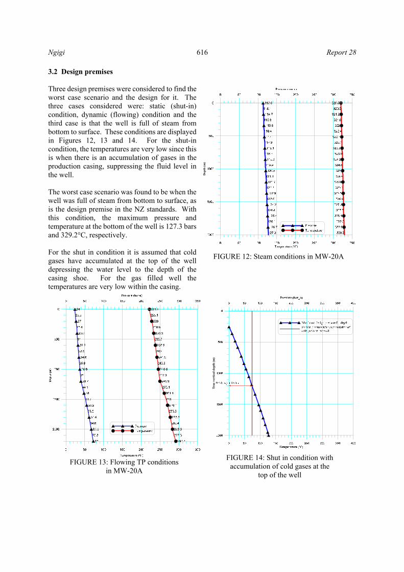
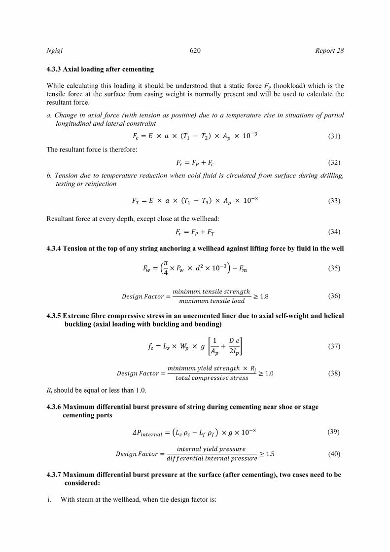
3.2 Design premises Three design premises were considered to find the worst case scenario and the design for it. The three cases considered were: static (shut-in) condition, dynamic (flowing) condition and the third case is that the well is full of steam from bottom to surface. These conditions are displayed in Figures 12, 13 and 14. For the shut-in condition, the temperatures are very low since this is when there is an accumulation of gases in the production casing, suppressing the fluid level in the well. The worst case scenario was found to be when the well was full of steam from bottom to surface, as is the design premise in the NZ standards. With this condition, the maximum pressure and temperature at the bottom of the well is 127.3 bars and 329.2°C, respectively. For the shut in condition it is assumed that cold gases have accumulated at the top of the well depressing the water level to the depth of the casing shoe. For the gas filled well the temperatures are very low within the casing.
Dep
th (
m)
FIGURE 12: Steam conditions in MW-20A
FIGURE 13: Flowing TP conditions in MW-20A
Tru
e ve
rtic
al d
epth
(m
)
FIGURE 14: Shut in condition with accumulation of cold gases at the
top of the well

Report 28 617 Ngigi
4. DESIGN CALCULATIONS 4.1 Introduction to design calculations After establishing the minimum casing depths for the different casing strings from the NZS 2403:1991 and NZS 2403:2015 design codes, the best casing weights, diameter and grade were calculated. The diameter of the casing is known, since the well is a regular well. A regular well casing string constitutes a 30” conductor casing, 20” surface casing, 13⅜” anchor casing, 9⅝” production casing and 7” slotted liners (Thórhallsson, 2015). The chosen grade for all the casing strings is K55, which has resistance to H2S and has been approved as it conforms to ANSI/NACE MR 0175/ISO 15156 (NZS 2403:2015). The casing grade is essential as it determines the burst pressure and axial tensile strength, while the wall thickness (weight) of the casing defines collapse (Finger and Blankenship, 2010). Design for burst, axial stress and collapse was done for a steam filled well as this was the worst case scenario. 4.2 Design calculation equations of well MW-20A with NZS 2403:1991 considering exact reservoir conditions Below are the equations used to calculate different casing loads and stresses using the NZS 2403:1991 code of practice for deep geothermal wells. For definition of parameters, see Nomenclature. 4.2.1 Axial loading before and during cementing
1010 (3)
4.2.2 Maximum bending stress in crooked wells 0.582 10 (4)
The calculated bending stress applies to a 9⅝”casing string which is run in the deviated part of the well.
1.8 (5)
4.2.3 Axial loading after cementing While calculating this loading it should be understood that a static force Fp, which is the tensile force at the surface from casing weight, is normally present and will be used to calculate the resultant force. a. Compressive force due to temperature rise with a partial longitudinal and lateral constraint 2.4 10 (6)
The resultant force is therefore,
(7)
1.2 (8)
b. Tension due to temperature reduction when cool fluid is circulated from the surface during drilling,
testing or reinjection 2.4 10 (9)

Ngigi 618 Report 28
Resultant force at every depth,
(10)
tensile
1.8 (11)
4.2.4 Tension at top of any string anchoring a wellhead against lifting force by fluid in the well
410 (12)
1.8 (13)
4.2.5 Design factor for the anchor casing thermal expansion into wellhead As the production casing expands thermally, a tensile force is applied to the anchor casing. To protect the anchor casing and the well head the following design factor is used.
1.5 (14)
4.2.6 Extreme fibre compressive stress in an uncemented liner due to axial self-weight and helical buckling (axial loading with buckling and bending) When the liners are run in hole after drilling to the final depth, they can either hang in the production casing or be left to rest at the bottom of the well. When the liners are left to rest at the bottom, compressive stresses are initiated due to axial self-weight and helical buckling. These stresses are calculated as below, in Equation 15:
12
(15)
The design factor should not be less than 1.2 and Rj should be equal or less than 1:
1.2 (16)
4.2.7 Maximum differential burst pressure of string near shoe or stage cementing ports 10 (17)
1.5 (18)
4.2.8 Maximum differential burst pressure will occur at the surface after cementing and two cases need to be considered: i. With steam at the wellhead, when the design factor is:
1.8 (19)
ii. With cold gas at the wellhead, the stress corrosion tensile limit of the steel should be used to determine the appropriate yield strength.

Report 28 619 Ngigi
4.2.9 Biaxial stress if the wellhead is fixed on casing being considered (combined effects of axial and circumferential tension)
√3
2 (20)
1.5
(21)
The steel strength is the lesser of the yield and the sulphide stress corrosion limit. 4.2.10 Hoop stressing (collapse) 1
10 (22)
1.2 (23)
4.2.11 Design for thermal expansion of a trapped liquid (inner casing string collapse resistance should exceed burst strength of outer string) 1.2 (24)
4.3 Design calculation equations of well MW-20A with NZS 2403:2015 considering exact reservoir conditions The following equations were used to calculate the different loading and stress scenarios using the NZS 2403:2015 code of practice for deep geothermal wells as described below. For definition of parameters, see Nomenclature. 4.3.1 Axial loading before and during cementing (25)
10 (26)
4
10 (27)
4
10 (28)
4.3.2 Maximum bending stress in non-vertical or curved wells Bending stress for casings run in non-vertical or curved wells is given by:
0.291 10 (29)
1.8 (30)
Ngigi 620 Report 28
4.3.3 Axial loading after cementing While calculating this loading it should be understood that a static force Fp (hookload) which is the tensile force at the surface from casing weight is normally present and will be used to calculate the resultant force.
a. Change in axial force (with tension as positive) due to a temperature rise in situations of partial longitudinal and lateral constraint
10 (31)
The resultant force is therefore:
(32)
b. Tension due to temperature reduction when cold fluid is circulated from surface during drilling, testing or reinjection
10 (33)
Resultant force at every depth, except close at the wellhead:
(34) 4.3.4 Tension at the top of any string anchoring a wellhead against lifting force by fluid in the well
410 (35)
1.8 (36)
4.3.5 Extreme fibre compressive stress in an uncemented liner due to axial self-weight and helical buckling (axial loading with buckling and bending) 1
2 (37)
1.0 (38)
Rj should be equal or less than 1.0. 4.3.6 Maximum differential burst pressure of string during cementing near shoe or stage cementing ports 10 (39)
1.5 (40)
4.3.7 Maximum differential burst pressure at the surface (after cementing), two cases need to be considered: i. With steam at the wellhead, when the design factor is:

Report 28 621 Ngigi
1.8 (41)
ii. With cold gas at the wellhead, when the stress corrosion tensile limit of the steel should be used to determine the appropriate yield strength.
4.3.8 Biaxial stress if wellhead is fixed on the casing being considered (combined effects of axial and circumferential tension) √5
2 (42)
Design factor should not be less than 1.5:
1.5 (43)
4.3.9 Hoop stressing (collapse) during casing cementing operations 10 (44)
1.2 (45)
4.3.10 Hoop stressing (collapse)-during production operations, annulus is at formation pressure
Pz=Pf
1.2 (46)
4.4 ISO/TR 10400 The above equations from the two design codes were used to calculate casing loads assuming a well full of steam from bottom to surface. To check the burst, collapse and axial stress adequacy of the chosen casing strings, the ISO/TR 10400 technical report was used to calculate the allowable limits by computing the design factors and checking against the minimum design factors in the design codes (ISO/TR 10400, 2007). The formulas below from ISO/TR 10400 technical report were used to calculate the conformity. For definition of parameters, see Nomenclature. 4.4.1 External pressure resistance (collapse) Collapse is dependent on the D/t ratio of the casing. For K55 casing grade, the ratio delineates the type of collapse that is going to occur, thereby giving the equation to be used to calculate the collapse limit for the casing. Table 1 below shows the various D/t ratio ranges for K55 and the type of collapse in that range.
TABLE 1: D/t ratio ranges for K55
D/t ratio
14.81 and less Yield strength collapse 14.81 25.01 Plastic collapse 25.01 37.21 Transition collapse 37.21 and greater Elastic collapse
Ngigi 622 Report 28
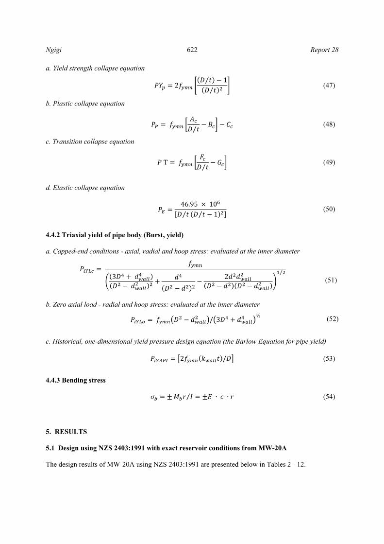
a. Yield strength collapse equation
2
⁄ 1⁄
(47)
b. Plastic collapse equation
⁄ (48)
c. Transition collapse equation
T⁄
(49)
d. Elastic collapse equation 46.95 10
⁄ ⁄ 1 (50)
4.4.2 Triaxial yield of pipe body (Burst, yield) a. Capped-end conditions - axial, radial and hoop stress: evaluated at the inner diameter
3
2⁄
(51)
b. Zero axial load - radial and hoop stress: evaluated at the inner diameter
/ 3½
(52)
c. Historical, one-dimensional yield pressure design equation (the Barlow Equation for pipe yield) 2 / (53)
4.4.3 Bending stress ⁄ ∙ ∙ (54)
5. RESULTS 5.1 Design using NZS 2403:1991 with exact reservoir conditions from MW-20A The design results of MW-20A using NZS 2403:1991 are presented below in Tables 2 - 12.

Report 28 623 Ngigi
5.1.1 Collapse and burst Below in Tables 2 and 3 collapse and burst pressures for the different casing sizes are shown and the calculated design factors. Collapse has been calculated considering the annulus is filled with 1.85 kg/l of cement slurry, and water of mean specific volume of 0.988 l/kg at 50°C.
TABLE 2: Collapse pressure using NZS 2403:1991
CASING GRADE K55
COLLAPSE
Depth 1991 Code
(MPa)
Collapse resistance
(MPa)
Calculated design factor
Minimum design factor
lb/ft
Production casing (9⅝")
Top 10 0.08 26.84 326.51 1.20 47 Middle 600 4.93 26.84 5.44 1.20
Shoe 1200 9.86 26.84 2.72 1.20 Anchor casing (13⅜")
Top 10 0.08 7.89 95.94 1.20 54.5 Middle 170 1.40 7.89 5.64 1.20
Shoe 350 2.88 7.89 2.74 1.20 Surface Casing (20")
Top 10 0.08 3.53 42.94 1.20 94 Middle 40 0.33 3.53 10.74 1.20
Shoe 80 0.66 3.53 5.37 1.20
TABLE 3: Burst pressure using NZS 2403:1991
CASING GRADE K55
BURST
Depth 1991 Code
(MPa)
Internal yield pressure (MPa)
Calculated design factor
Minimum design factor
lb/ft
Production casing (9⅝")
Top 10 0.10 32.40 326.32 1.5 47 Middle 600 5.96 32.40 5.44 1.5
Shoe 1200 11.91 32.40 2.72 1.5 Anchor casing (13⅜")
Top 10 0.10 18.91 190.44 1.5 54.5 Middle 170 1.69 18.91 11.20 1.5
Shoe 350 3.48 18.91 5.44 1.5 Surface Casing (20")
Top 10 0.10 14.48 145.82 1.5 94 Middle 40 0.40 14.48 36.46 1.5
Shoe 80 0.79 14.48 18.23 1.5
Calculations for burst pressure consider a cement slurry density of 1.85 kg/l inside the casing and hot water of mean specific volume of 0.988 l/kg at 50°C in the annulus. 5.1.2 Axial loading before and during cementing During running of casing strings and cementing, casing axial tensile forces develop and act on the casing string, the calculated forces and design factors are shown in Table 4. Where the well is deviated for directional wells, stress due to bending is added to the hook load (tensile load). The bending stress in this case will be considered maximum at the kick off point (400 m), where the highest bending of the casing is expected. Bending stress will be added to the tensile load at the kick off depth. The casing string that is in the deviated section is the production casing (9⅝ casing). The maximum dog leg severity has been taken as 3° per 30 m.
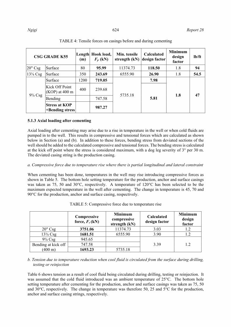
Ngigi 624 Report 28
TABLE 4: Tensile forces on casings before and during cementing
CSG GRADE K55 Length
(m) Hook load,
Fp (kN) Min. tensile
strength (kN)Calculated
design factor
Minimum design factor
lb/ft
20" Csg Surface 80 95.99 11374.73 118.50 1.8 94
13⅜ Csg Surface 350 243.69 6555.90 26.90 1.8 54.5
9⅝ Csg
Surface 1200 719.05
5735.18
7.98
1.8 47
Kick Off Point (KOP) at 400 m
400 239.68
5.81 Bending 747.58
Stress at KOP +Bending stress
987.27
5.1.3 Axial loading after cementing Axial loading after cementing may arise due to a rise in temperature in the well or when cold fluids are pumped in to the well. This results in compressive and tensional forces which are calculated as shown below in Section (a) and (b). In addition to these forces, bending stress from deviated sections of the well should be added to the calculated compressive and tensional forces. The bending stress is calculated at the kick off point where the stress is considered maximum, with a dog leg severity of 3° per 30 m. The deviated casing string is the production casing. a. Compressive force due to temperature rise where there is partial longitudinal and lateral constraint When cementing has been done, temperatures in the well may rise introducing compressive forces as shown in Table 5. The bottom hole setting temperature for the production, anchor and surface casings was taken as 75, 50 and 30°C, respectively. A temperature of 120°C has been selected to be the maximum expected temperature in the well after cementing. The change in temperature is 45, 70 and 90°C for the production, anchor and surface casing, respectively.
TABLE 5: Compressive force due to temperature rise
Compressive force, Fc (kN)
Minimum compressive
strength (kN)
Calculated design factor
Minimum design factor
20" Csg 3751.06 11374.73 3.03 1.2 13⅜ Csg 1681.51 6555.90 3.90 1.2 9⅝ Csg 945.65
3.39 1.2 Bending at kick off (400 m)
747.58 1693.23 5735.18
b. Tension due to temperature reduction when cool fluid is circulated from the surface during drilling,
testing or reinjection Table 6 shows tension as a result of cool fluid being circulated during drilling, testing or reinjection. It was assumed that the cold fluid introduced was an ambient temperature of 25°C. The bottom hole setting temperature after cementing for the production, anchor and surface casings was taken as 75, 50 and 30°C, respectively. The change in temperature was therefore 50, 25 and 5°C for the production, anchor and surface casing strings, respectively.

Report 28 625 Ngigi
TABLE 6: Tension when cool fluid is circulated in the well
Casing string Tension force, Ft
(kN)
Minimum tensile
strength (kN)
Calculated design factor
Minimum design factor
lb/ft
20" Csg 177.13 11374.73 64.22 1.8 94
13⅜ Csg 510.46 6555.90 12.84 1.8 54.5
9⅝ Csg 893.11
5735.18 3.50 1.8 47 Bending at kick off (400 m)
747.58
1640.69 5.1.4 Tension at the top of any string anchoring a wellhead against a lifting force by fluid in a well The anchor casing holds the wellhead after the well has been completed. Lifting force by fluid in the well may introduce tension at the top of the anchor casing. The tension forces are calculated as shown in Table 7. The maximum well head pressure is 11.36 MPa from the worst case scenario where the well is assumed to be filled with steam from bottom to surface. The weight of the selected master valve, Class 900 manufactured by Alfa Oil, is 2 tonnes.
TABLE 7: Tension on anchor casing due to lifting force by fluid in the well
Casing string anchoring
w/head
Fw (Tension at top) (kN)
Min. tensile strength (kN)
Calculated design factor
Min. design factor
lb/ft
13⅜ Csg 896.42 87775.69 97.92 1.80 72 5.1.5 Design factor for anchor casing thermal expansion into wellhead During the operation of the well the production casing may rise into the wellhead, introducing stresses onto the anchor casing. Table 8 shows the design factor for this situation and how the best casing string is arrived at.
TABLE 8: Design factor for anchor casing thermal expansion into wellhead
lb/ft
Anchor casing tensile
strength (kN)
Rising casing (prod. casing) compressive
strength (kN)
Calculated design factor
Minimum design factor
54.5 6555.90 5735.18 1.14 1.50 61 7389.71 5735.18 1.29 1.50 68 8216.98 5735.18 1.43 1.50 72 8775.69 5735.18 1.53 1.50 Adequate
5.1.6 Extreme fibre compressive stress in an uncemented liner due to axial self-weight and helical buckling Slotted liners are run in hole after drilling to the determined depth. The slotted liners allow the steam into the well and up to the surface through the production casing. The liners may hang using a liner hanger or they may be rested at the bottom of the well. When rested at the bottom, as is the practice in Menengai, compressive forces due to axial self-weight and helical buckling need to be considered. The slots in the liner are 20 mm in diameter and there are eight slots around the circumference of the liner.

Ngigi 626 Report 28
The distance in between the rows along the axial direction is 60 mm, resulting in 16 rows of slots for every 1 m of the liner. Due to the slotting, the liner cross section area and the moment of inertia is reduced and were calculated as 4,520.91 mm2 and 16,238,393 mm4. The joint strength for the liner was 2,832.64 kN with a joint efficient of 0.96 required for this calculation. The compressive stress calculated is shown in Table 9.
TABLE 9: Compressive stress in uncemented liner due to axial self-weight and helical buckling
7" Csg 26 lb/ft
Depth of liner
Compressive stress (MPa)
Calculated design factor
Minimum design factor
Top 10.00 1.63 223.03 1.20 Middle 640.00 104.40 3.48 1.20 Bottom 830.00 135.40 2.69 1.20
5.1.7 Maximum differential burst pressure at the surface after cementing The maximum differential burst pressure occurs at the surface after cementing with steam or cold gas at the well head. The design factor calculation for this case is shown in Table 10 with the minimum design factor from the 1991 code for comparison. The casing string considered here is the anchor casing as it supports the wellhead.
TABLE 10: Design factor for maximum differential burst pressure at surface after completion
lb/ft
Well head Press (MPa)
Well head Temp. (°C)
Temp. reduction factor on
yield strength
Internal yield strength (anchor) (MPa)
Calculated design factor
Minimum design factor
54.5 11.36 320.5 0.95 18.91 1.58 1.8 72 11.36 320.5 0.95 25.5 2.13 1.8 Adequate
5.1.8 Biaxial stress if the wellhead is fixed on the casing being considered (combined effects of axial and circumferential tension) After drilling is completed a wellhead is placed on the anchor casing, introducing biaxial stress. The calculation of this stress is based on the upper casing joints interacting with the well head. The well head pressure used for this calculation is the maximum expected pressure of 11.36 MPa. Table 11 displays the calculation of biaxial stress and the design factor comparison.
TABLE 11: Biaxial stress on anchor casing
Biaxial stress, ft (MPa)
Yield strength (MPa)
Calculated design factor
Minimum design factor
lb/ft
13⅜ Csg 163.32 379 2.32 1.5 72 5.1.9 Design for the thermal expansion of a trapped liquid (inner casing string collapse resistance should exceed burst strength of outer string) The 1991 design code instructs that a sacrificial casing is needed if there is trapped liquid within a cemented annulus. The design is such that if the trapped fluid expands, the outer casing should burst rather than the production casing collapse. To allow this, then the collapse resistance for the production casing should be higher than the burst of the outer casing. The weight of the 13⅜” casing and 9⅝”

Report 28 627 Ngigi
casing is 54.5 and 47 lb/ft, respectively. In Table 12 the calculated design factor is compared with the desired design factor.
TABLE 12: Design factor for thermal expansion of a trapped liquid
Prod. csg collapse (MPa)
Anchor csg burst (MPa)
Calculated design factor
Minimum design factor
13⅜ Csg 18.91 1.42 1.2
9⅝ Csg 26.84 5.2 Design using NZS 2403:2015 with reservoir conditions from MW-20A The design results of MW-20A using NZS 2403:2015 are presented below in Tables 13-23. 5.2.1 Collapse and burst The collapse and burst pressure for the three casing strings are shown in Tables 13 and 14 with the design factors also being compared. Collapse has been calculated considering the annulus is filled with 1.85 kg/l of cement slurry and water of mean specific volume of 0.988 l/kg at 50°C. Calculations for burst pressure consider a cement slurry density of 1.85 kg/l inside the casing and hot water of mean specific volume of 0.988 l/kg at 50°C in the annulus.
TABLE 13: Collapse pressure using NZS 2403:2015
CSG GRADE K55 COLLAPSE
Depth 2015 Code
ISO/TR 10400
Calculated design factor
Minimum design factor
lb/ft
Production casing (9⅝")
Top 10 0.08 26.84 317.36 1.20 47 Middle 600 5.07 26.84 5.29 1.20
Shoe 1200 10.15 26.84 2.64 1.20 Anchor casing (13⅜")
Top 10 0.08 7.89 93.25 1.20 54.5 Middle 240 2.03 7.89 3.88 1.20
Shoe 470 3.97 7.89 1.99 1.20 Surface casing (20")
Top 10 0.08 3.53 41.74 1.20 94 Middle 70 0.59 3.53 5.98 1.20
Shoe 140 1.18 3.53 2.99 1.20
TABLE 14: Burst pressure using NZS 2403:2015
CSG GRADE K55 BURST
Depth 2015 Code
ISO/TR 10400
Calculated design factor
Minimum design factor
lb/ft
Production casing (9⅝")
Top 10 0.08 32.40 383.15 1.5 47 Middle 600 5.07 32.40 6.39 1.5
Shoe 1200 10.15 32.40 3.19 1.5 Anchor casing (13⅜")
Top 10 0.08 18.91 223.61 1.5 54.5 Middle 240 2.03 18.91 9.32 1.5
Shoe 470 3.97 18.91 4.76 1.5 Surface Casing (20")
Top 10 0.08 14.48 171.22 1.5 94 Middle 70 0.59 14.48 24.46 1.5
Shoe 140 1.18 14.48 12.23 1.5
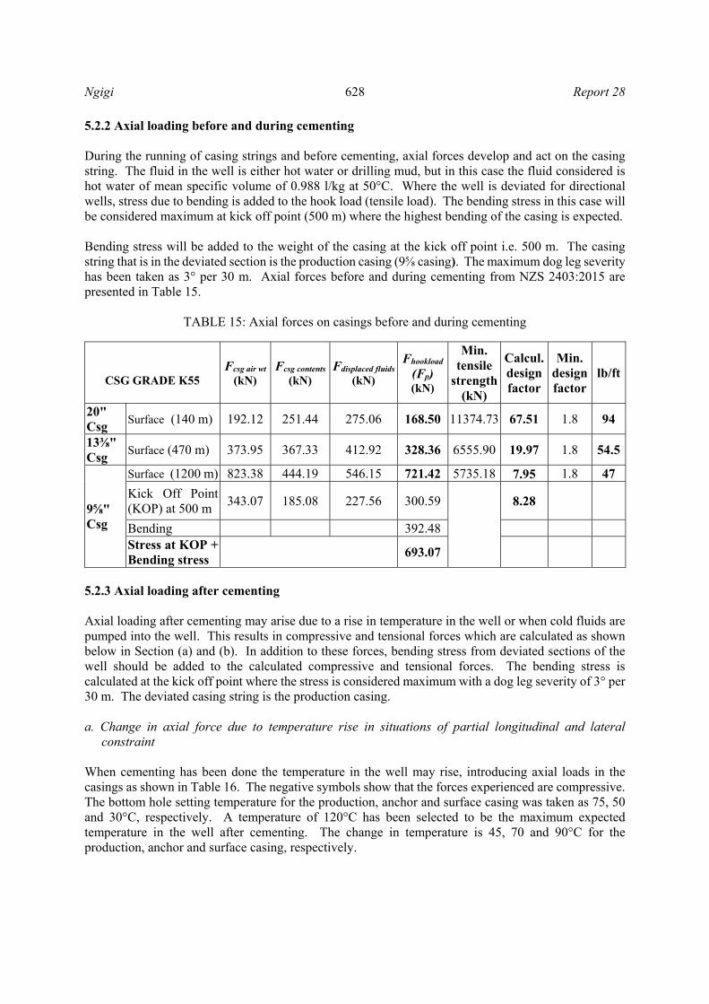
Ngigi 628 Report 28
5.2.2 Axial loading before and during cementing During the running of casing strings and before cementing, axial forces develop and act on the casing string. The fluid in the well is either hot water or drilling mud, but in this case the fluid considered is hot water of mean specific volume of 0.988 l/kg at 50°C. Where the well is deviated for directional wells, stress due to bending is added to the hook load (tensile load). The bending stress in this case will be considered maximum at kick off point (500 m) where the highest bending of the casing is expected. Bending stress will be added to the weight of the casing at the kick off point i.e. 500 m. The casing string that is in the deviated section is the production casing (9⅝ casing). The maximum dog leg severity has been taken as 3° per 30 m. Axial forces before and during cementing from NZS 2403:2015 are presented in Table 15.
TABLE 15: Axial forces on casings before and during cementing
5.2.3 Axial loading after cementing Axial loading after cementing may arise due to a rise in temperature in the well or when cold fluids are pumped into the well. This results in compressive and tensional forces which are calculated as shown below in Section (a) and (b). In addition to these forces, bending stress from deviated sections of the well should be added to the calculated compressive and tensional forces. The bending stress is calculated at the kick off point where the stress is considered maximum with a dog leg severity of 3° per 30 m. The deviated casing string is the production casing. a. Change in axial force due to temperature rise in situations of partial longitudinal and lateral
constraint When cementing has been done the temperature in the well may rise, introducing axial loads in the casings as shown in Table 16. The negative symbols show that the forces experienced are compressive. The bottom hole setting temperature for the production, anchor and surface casing was taken as 75, 50 and 30°C, respectively. A temperature of 120°C has been selected to be the maximum expected temperature in the well after cementing. The change in temperature is 45, 70 and 90°C for the production, anchor and surface casing, respectively.
CSG GRADE K55
Fcsg air wt
(kN) Fcsg contents
(kN) Fdisplaced fluids
(kN)
Fhookload
(Fp) (kN)
Min. tensile
strength (kN)
Calcul. design factor
Min. design factor
lb/ft
20" Csg
Surface (140 m) 192.12 251.44 275.06 168.50 11374.73 67.51 1.8 94
13⅜" Csg
Surface (470 m) 373.95 367.33 412.92 328.36 6555.90 19.97 1.8 54.5
9⅝" Csg
Surface (1200 m) 823.38 444.19 546.15 721.42 5735.18 7.95 1.8 47
Kick Off Point (KOP) at 500 m
343.07 185.08 227.56 300.59
8.28
Bending 392.48 Stress at KOP + Bending stress
693.07
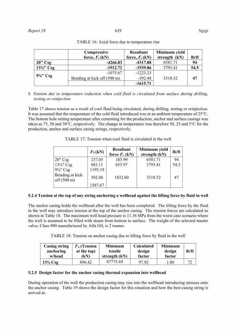
Report 28 629 Ngigi
TABLE 16: Axial force due to temperature rise
Compressive force, Fc (kN)
Resultant force, Fr (kN)
Minimum yield strength (kN) lb/ft
20" Csg -4266.83 -4317.88 6581.71 94 13⅜" Csg -1912.72 -1939.86 3793.41 54.5
9⅝" Csg
-1075.67 -1223.233318.52 47 Bending at kick off (500 m) -392.48
-1615.71 b. Tension due to temperature reduction when cold fluid is circulated from surface during drilling,
testing or reinjection Table 17 shows tension as a result of cool fluid being circulated, during drilling, testing or reinjection. It was assumed that the temperature of the cold fluid introduced was at an ambient temperature of 25°C. The bottom hole setting temperature after cementing for the production, anchor and surface casings was taken as 75, 50 and 30°C, respectively. The change in temperature was therefore 50, 25 and 5°C for the production, anchor and surface casing strings, respectively.
TABLE 17: Tension when cool fluid is circulated in the well
FT (kN) Resultant
force Fr (kN) Minimum yield strength (kN)
lb/ft
20" Csg 237.05 185.99 6581.71 94 13⅜" Csg 683.11 655.97 3793.41 54.5 9⅝" Csg 1195.19
1832.60 3318.52 47 Bending at kick off (500 m)
392.48
1587.67 5.2.4 Tension at the top of any string anchoring a wellhead against the lifting force by fluid in well The anchor casing holds the wellhead after the well has been completed. The lifting force by the fluid in the well may introduce tension at the top of the anchor casing. The tension forces are calculated as shown in Table 18. The maximum well head pressure is 11.36 MPa from the worst case scenario where the well is assumed to be filled with steam from bottom to surface. The weight of the selected master valve, Class 900 manufactured by Alfa Oil, is 2 tonnes.
TABLE 18: Tension on anchor casing due to lifting force by fluid in the well
Casing string
anchoring w/head
Fw (Tension at the top)
(kN)
Minimum tensile
strength (kN)
Calculated design factor
Minimum design factor
lb/ft
13⅜ Csg 896.42 87775.69 97.92 1.80 72 5.2.5 Design factor for the anchor casing thermal expansion into wellhead During operation of the well the production casing may rise into the wellhead introducing stresses onto the anchor casing. Table 19 shows the design factor for this situation and how the best casing string is arrived at.

Ngigi 630 Report 28
TABLE 19: Design factor for anchor casing thermal expansion into wellhead
lb/ft Anchor
casing tensile strength
Rising casing (Prod. csg) compressive
strength
Calculated design factor
Minimum design factor
54.5 6555.90 5735.18 1.14 1.50 61 7389.71 5735.18 1.29 1.50 68 8216.98 5735.18 1.43 1.50 72 8775.69 5735.18 1.53 1.50 Adequate
5.2.6 Extreme fibre compressive stress in an uncemented liner due to axial self-weight and helical buckling Slotted liners are run in hole after drilling to the determined depth. The slotted liners allow geothermal fluid into the well and up to the surface through the production casing. The liners may hang with the help of a liner hanger or they may be rested at the bottom of the well. When rested at the bottom, as is the practice in Menengai, compressive forces due to axial self-weight and helical buckling need to be considered. The slots in the liner are assumed to be 20 mm in diameter and with eight slots around the circumference of the liner. The distance between the rows along the axial direction is 60 mm resulting in 16 rows of slots for every 1 m of the liner. Due to the slotting, the liner cross section area and the moment of inertia are reduced and were calculated as 4520.91 mm2 and 16238393mm4. The joint strength for the liner was 2832.64 kN with a joint efficient of 0.96 required for this calculation. The compressive stress calculated is shown in Table 20.
TABLE 20: Compressive stress in uncemented liner due to axial self-weight and helical buckling
7" Csg 26 lb/ft
Depth of
liner Compressive stress (MPa)
Calculated design factor
Minimum design factor
Top 10.00 1.63 223.03 1.0 Middle 640.00 104.40 3.48 1.0 Bottom 830.00 135.40 2.69 1.0
5.2.7 Maximum differential burst pressure at the surface (after cementing) The highest differential burst pressure is expected to occur at the surface after cementing. The calculated design factor for this case is compared with the calculated design factor in Table 21. The anchor casing is considered here as it supports the well head.
TABLE 21: Design factor for maximum differential burst pressure at surface after cementing
lb/ft Well head
press. (MPa)
Well head temp. (°C)
Temp. reduction
factor
Internal yield strength
(anchor) (MPa)
Calculated design factor
Min. design factor
54.5 11.36 320.5 0.8 18.91 1.33 1.80 72 11.36 320.5 0.8 25.5 1.80 1.80 Adequate
5.2.8 Biaxial stress if wellhead is fixed on casing considered (combined effects of axial and circumferential tension) Biaxial stresses are introduced on the casing string anchoring the wellhead. The biaxial stress is calculated below in Table 22 for a 13⅜” casing string considering the upper casing joints interacting with the well head. The calculated design factor is then compared with the minimum design factor from the design code. The well head pressure used for this calculation is the maximum expected pressure of 11.36 MPa.

Report 28 631 Ngigi
TABLE 22: Biaxial stress on anchor casing
Biaxial stress,
ft (MPa) Yield strength
(MPa) Calculated
design factor Min. design
factor lb/ft
13⅜ Csg 210.85 379 1.80 1.5 72 5.2.9 Hoop stressing (collapse)-during production The worst case scenario for the design has been chosen to be when the well is filled with steam from bottom to surface during production. Considering this case, collapse is computed at the production shoe so as an appropriate casing string can be provided. The differential collapse pressure is shown in Table 23 and the design factor calculated. The fluid inside the casing is steam and therefore the density is assumed to be zero.
TABLE 23: Collapse during production
Differential external pressure
ΔPexternal
Production casing collapse pressure
at 1200 m
Calculated design factor
Min. design factor
21.7782 26.83 1.23 1.20 5.3 Joint strength The selected casing strings need to be checked for strength at the connections, or at the joints. The chosen type of connection is a buttress and Table 24 shows the strength of the joints for each casing string and the joint efficiency. According to the society of petroleum engineers it is imperative during casing design to appreciate that the API joint-strength values are a function of the ultimate tensile strength (SPE, 2015).
TABLE 24: Joint strength and efficiency
Casing lb/ft Joint strength
(kN) Pipe body
strength (kN) Joint
efficiency 20 94 6576.49 11374.73 0.58
13⅜ 54.5 4612.96 6555.90 0.70 9⅝ 47 4444.00 5735.18 0.77 7" 26 2832.64 2961.20 0.96
6. DISCUSSION The design of a well drilled to 2000 m using the two New Zealand design codes was done using the high temperature and pressure geothermal well MW-20A in Menengai as a reference well to estimate the reservoir pressure to be used in the design. The casing loads were evaluated for collapse, burst and axial stresses and the best casing size suggested. The casing strings were selected from the drilling data handbook (Gabolde and Nguyen, 2014) and were as follows:
Production casing was 9⅝” with a weight of 47 lb/ft (see further discussion in section 6.12); Anchor casing was 13⅜” with a weight of 54.5 lb/ft, however, due to thermal expansion of the
casing into well head, calculations showed that the upper part of the string was to be replaced with 2 joints of 72 lb/ft as will be explained later in this chapter, assuming that it was the minimum rise of the production casing that causes this stress;
Ngigi 632 Report 28
The surface casing that was found to be adequate was 20” with 94 lb/ft. All the calculations for the casing loads have been based on these casing strings and the results are discussed herein. 6.1 Collapse and burst Collapse pressure for the production casing at 1200 m from NZS 2403:1991 at the shoe was 9.86 MPa with a design factor of 2.72 while for the same depth the collapse from NZS 2403:2015 was 10.15 MPa and a design factor of 2.64. The minimum design factor from both codes is 1.2 hence the design was adequate. Burst pressure at the shoe for the production casing at 1200 m calculations from NZS 2403:1991 showed a pressure of 10.15 MPa and a design factor of 3.19. NZS 2403:2015 calculations for burst resulted to a pressure of 10.15 MPa and a design factor of 3.19. The minimum design factor for burst was 1.5 from both codes showing that the provided production casing string was sufficient. The collapse pressure at the shoe for the anchor casing was 2.88 MPa and a design factor of 2.74 as given by NZS 2403:1991 at a shoe depth of 350 m. The NZS 2403:2015 calculations give a collapse pressure of 3.97 MPa and a design factor of 1.99 at a shoe depth of 470 m. Both design codes provide a minimum design factor of 1.5 and thus this design is sufficient. The burst pressure for the anchor casing at the shoe was calculated as 2.96 MPa with a design factor of 6.39 using the NZS 2403:1991 design code at a shoe depth of 350 m. From NZS 2403:2015 the burst at 470 m shoe depth was found to be 3.97 MPa and design factor of 4.76. The minimum design factor is 1.5 for the two codes and thus the choice of the casings was appropriate. The surface casing was set at 80 m using the NZS 2403:1991 code and the collapse pressure at this depth was 0.66 MPa with a design factor of 5.37. The NZS 2403:2015 design code placed the surface casing shoe at 140 m and the collapse pressure was 1.18 MPa with a design factor of 2.99. The minimum design factor for collapse from the two codes is 1.5 concluding that the selected casing string was satisfactory. Burst pressure for the surface casing (20” casing) was also computed considering the two different codes. At a shoe depth of 80 m and using the NZS 2403:1991 code the burst pressure was 0.68 MPa and the design factor was 21.4. The 2015 New Zealand code, NZS 2403:2015 gives a burst pressure of 1.18 MPa and a design factor of 12.23. The minimum design factor for burst from the two design codes is 1.5 and so the design is correct. 6.2 Axial loading before and during cementing Axial loads before and during cementing were calculated from both codes. The computed axial load for the surface casing (20”) using NZS 2403:1991 was 95.99 kN and the design factor was 118.5. Results from NZS 2403:2015 showed an axial load of 168.5 kN. The design factor for this case was 67.51 and the minimum design factor was 1.8 for the two codes. Given the computed design factors the design was found to be sound and safe. For the anchor casing the NZS 2403:1991 design standard provided an axial load of 243.69 kN and design factor of 26.9 while the 2015 NZS 2403:2015 showed an axial load of 328.36 kN and a design factor of 19.97. It was deduced from the calculated design factors that the design was adequate as the minimum design factor from the design codes was 1.8.
Report 28 633 Ngigi
The production casing string axial load was computed from NZS 2403:1991 as 719.05 kN from the shoe and the calculated design factor was 7.98 without considering bending. However, it should be noted that this casing string is placed in the deviated part of the well and bending stresses need to be accounted for by adding the stress to the tensile load at the kick off depth. The bending stress calculated at the kick off point (400 m) was 747.58 kN and the tensile load at the kick off depth was calculated as 239.68 kN; the resultant was 987.27 kN with a design factor of 5.81. Similarly the NZS 2403:2015 was used to calculate the axial loading on the production casing and the results showed that the load was 721.42 kN from the shoe without considering bending with a design factor of 7.95. The bending force was calculated as 392.48 kN and was added to the casing weight (tensile load) at the kick off (500 m) computed as 300.59 kN. The resultant load was 693.07 kN and a design factor of 8.28 was calculated. When compared against the minimum design factor of 1.8 from the two codes, the design was found to be safe. 6.3 Axial loading after cementing After casing cementing has been done, the temperature variations in the well will introduce stresses in the casing. A rise in temperature will result in compressive stresses in the well and if the temperature is lowered in the well, especially during drilling, testing or reinjection, then tension stresses are introduced in the casings. The calculated stresses from the rise or reduction of temperature should be added to the axial loading before and during cementing in clause 6.2 as it exists as a static force to arrive at a resultant force on the casing string. 6.3.1 Compressive forces after cementing due to a rise in temperature in situations of partial longitudinal and lateral restraint After cementing is done and the bottom hole setting temperature has been noted the formation may start to heat up, leading to an increase in temperature, and the result is that compressive forces will build up on the casing. The bottom hole setting temperature for the production, anchor and surface casing was 75, 50 and 30°C, respectively. A temperature of 120°C was chosen to be the maximum expected temperature in the well after cementing. Design computation for axial loading after cementing from NZS 2403:1991 for the production casing portrayed a compressive force of 945.65 kN, and adding the additional compressive force of 747.58 kN from bending the resultant force was 1693.23 kN and the design factor was 3.39 compared to the minimum design factor of 1.2. The anchor casing computation of the force due to rise in temperature showed a compressive force of 1681.51 kN and a design factor of 3.9 compared to the minimum design factor of 1.2. More so using the same design code the calculated surface casing compressive force was 3751.06 kN and a design factor of 3.03 whereas the minimum design factor was 1.2. Given the calculated design factors it is evident that they are all above the minimum design factor of 1.2 and this confirms that the design adequate. Resultant compressive forces from NZS 2403:2015 were obtained as follows; the production casing had a force of 1615.71 kN including a bending force of 372.48 kN, and for the anchor casing the force was 1939.86 kN and the surface casing had 4317.88 kN. Using the design code guides to check for the design adequacy, the resultant forces have to be checked against the minimum yield strength of each of the casing strings. The minimum yield strength for the production, anchor and surface casing was computed as 3318.52, 3793.41 and 6581.71 kN, respectively. Doing a comparison of the calculated compressive forces and the minimum yield strength of the different casing strings, the design was found to be appropriate.
Ngigi 634 Report 28
6.3.2 Tension due to temperature reduction when cold fluid is circulated from surface After cementing there is a need to continue drilling or to do a test on the well, while in other cases the well might be used for reinjection. In such cases, cold fluids are introduced into the well, lowering the existing temperature. Lowering of the temperature introduces tension forces into the casings and this may become significant if very cold fluids are used. The following are results for tension induced forces due to cooling in the well. It was assumed that the temperature of the cold fluid introduced is 25°C. The bottom hole setting temperature for the production, anchor and surface casing was taken as 75, 50 and 30°C, respectively Using NZS 2403:2015 the tension forces on the surface casing were found to be 177.13 kN and the calculated design factor was 64.22, the tension on the anchor casing was 510.46 kN with a design factor of 12.84 and the tension on the production casing, including tension of 747.58 kN due to bending, was 1640.69 kN with a design factor of 3.5. The design was checked against the minimum design factor of 1.8 and hence found to be safe. The NZS 2403:2015 design code showed a tension of 185.99 kN on the surface casing, 655.97 kN on the anchor casing and 1832.6 kN on the production casing, including a bending tensional force of 392.48 kN. Given the yield strength of the surface, anchor and production casing as 6581.71, 3793.41 and 3318.52 kN, respectively, the design showed that the chosen casing weights were adequate. 6.4 Tension at the top of a casing string anchoring a wellhead against the lifting force by fluid in the well Tension forces do occur at the top of the casing string that holds the well head. This force needs to be calculated so that the best anchor casing can be chosen. In this case the casing holding the well head is the 13⅜”casing with a weight of 72 lb/ft. The calculation for this force is the same from the two standards and the force calculated is 857.95 kN with a design factor of 102.31. This design is appropriate as the minimum design factor for this case is 1.8. 6.5 Design factor for anchor casing thermal expansion into wellhead The production casing, which is cemented inside the anchor casing, may in some instances rise and elongate at the free end up at the wellhead and this is where it is advised to have an expansion spool at the wellhead. The design factor required for a successful design is 1.5 for NZS 2403:1991 and 1.4 for NZS 2403:2015. The previously chosen anchor casing weight of 54.5 lb/ft could not provide an adequate design. This necessitated the changing of the design of the top two joints of the anchor casing by increasing their weight to 72 lb/ft for the design to hold. After calculations using the 72 lb/ft anchor casing a design factor of 1.53 was obtained against a minimum design factor of 1.5 and 1.4 for NZS 2403:1991 and NZS 2403:2015 respectively hence this design criterion holds for the two New Zealand codes. 6.6 Maximum differential burst pressure at the surface after cementing After the casing cementing the maximum differential burst pressure will occur at the surface and the anchor casing has to be sufficient enough to hold the pressure. The design calculation from the two New Zealand standards is the same, however the temperature reduction factors for yield are different. The NZS 2403:2015 design code has revised the reduction factors downwards, and for example in this case considering a temperature of 320.5°C at the wellhead the reduction factor for yield strength from NZS 2403:2015 is 0.8 while the one from NZS 2403:1991 is 0.95. Calculated design factor from NZS
Report 28 635 Ngigi
2403:1991 is 2.13 and the one from NZS 2403:2015 is 1.8. The minimum design factor is 1.8 hence the design is adequate. 6.7 Biaxial stress if wellhead is fixed on casing being considered Considering that the wellhead will be fixed on the anchor casing, biaxial stress is bound to occur and therefore needs to be incorporated into the design. The biaxial stress is a combined effect of axial and circumferential tension. Biaxial stress calculated from NZS 2403:1991 was 118.21 MPa with a calculated design factor of 3.21 while the NZS 2403:2015 design code gave a biaxial stress of 152.61 MPa with a design factor of 2.48. The minimum design factor from the two codes is 1.5, hence the design is appropriate. 6.8 Hoop stressing (Collapse during production) NZS 2403:2015 During production operations the annulus is at the formation pressure, meaning that the external fluid pressure at the production casing shoe is equal to the pore pressure. To take care of this collapse NZS 2403:2015 provides a minimum design factor of 1.2. The calculated design factor for the production casing at the shoe is 1.23 and thus the design is adequate. 6.9 Design for thermal expansion of a trapped liquid NZS 2403:1991 NZS 2403:1991 design code provides a minimum design factor of 1.2 for the thermal expansion of trapped fluids. The thermal expansion of trapped fluids results in pressures exceeding the strength of casing strings in either collapse or burst. The code therefore provides a design of a production casing which has a higher collapse resistance than the burst resistance of the outer casing so that the integrity of the production casing is preserved, in case there is an occurrence of expansion of trapped fluids. The calculated design factor in this scenario is 1.42 and the minimum design factor is 1.2 and thus the design is safe. 6.10 Extreme fibre compressive stress in an uncemented liner due to axial self-weight and helical buckling After drilling to total depth a well may be completed by running a liner, screen or left barefoot that is without a liner or a screen. Where liners are run in hole they can hang on the liner hanger or left to rest at the bottom of the well, which is the practice in Menengai. When liners are left to rest at the bottom of the well there will be compressive forces on the liner due to self-weight and helical buckling. The liner will tend to buckle in the well as the well diameter is larger than the diameter of the well. Due to this the liner should be checked so it does not exceed its minimum yield. Calculations for the compressive stress are the same from the two New Zealand codes and the maximum stress is 195.76 MPa at the bottom of the liner with a design factor of 2.69. The minimum design factor from NZS 2403:1991 and NZS 2403:2015 is 1.2 and 1.0, respectively and therefore the design is adequate. 6.11 Connection/joint strength The casing connection that was chosen for the casing strings was a buttress. The joint strength for surface, anchor, production and slotted liner was calculated as 6576.49, 4612.96, 4444 and 2832.64 kN,

Ngigi 636 Report 28
respectively. The connection efficiency was 0.58, 0.7, 0.77 and 0.96 for the surface, anchor, production and slotted liners, respectively. 6.12 Corrosion NZS 2403:1991 and NZS 2403:2015 design codes recognize the effect of corrosion which reduces the cross section area of casings. The production casing is the main conveyor of geothermal fluid to the surface and into the wellhead. This casing will be prone to corrosion where conditions for corrosion are favourable. From the design that has been carried out, the production casing string selected is 9⅝” 53.5 lb/ft. Closer examination shows that the weight of this casing can be reduced to 36 lb/ft and the design will still be adequate as the collapse design factor will be 1.23, compared to a minimum design factor of 1.2. However, due to corrosion effects during the life time of the well reducing the thickness would compromise the anticipated well life. Corrosion is regarded to be acceptable for material used at a rate of 0.1 mm per year from studies conducted in Iceland on wells across the country (Thorbjornson, I., pers.comm., September, 2015); this translates to 2 mm in 20 years. If the weight of the production casing is reduced from 53.5 to 36 lb/ft the thickness is reduced by 3 mm. Hence if corrosion is to be considered the chosen casing of 53.5 lb/ft is adequate during the life of the well estimated to be 20 years. 6.13 Well head selection The design premise adopted for designing the considered well was the steam filled condition as this presented the worst case scenario. The expected pressure and temperature at the wellhead in this condition is 11.36MPa and 320.5°C as shown in Figure 15. The most suitable wellhead from Figure 15 is an ANSI 900 or Class 900 master valve. 7. CONCLUSIONS AND RECOMMENDATION The two New Zealand design codes have been used to design a 2000 m well, although in principle the two codes differ as will be detailed here. NZS 2403:1991 uses the overburden of the underlying formation as the maximum pressure boundary while determining the minimum casing depth, whereas the 2015 code, NZS 2403:2015 adopts the fracture pressure as the maximum boundary for minimum casing determination. Increase in temperature reduces the yield strength, modulus of elasticity and tensile strength of steel and therefore reduction factors have been provided for various temperature ranges, quite notable is that the reduction factors in the 2015 design have been reduced compared to the ones previously found in the 1991 design code. For example, the temperature reduction factor for yield strength at a temperature of 300°C is 0.8 in the 2015 design code whereas in the 1991 code the reduction factor is 0.95.
FIGURE 15: Wellhead working pressure de-rating for flanges and valves conforming to
ANSI/ASME B16.5 and to API Spec 6A (New Zealand Standard, 2015)
Temperature (˚C)
Pre
ssur
era
ting
Report 28 637 Ngigi
Some of the minimum design factors have been reduced in the 2015 design code, for instance the minimum design factor for anchor casing expansion into the well head and compressive stress due to liner self-weight and helical buckling are 1.4 and 1.0, respectively, while in the 1991 code the minimum design factors are 1.5 and 1.2 respectively. The 1991 code accounts for the thermal expansion of fluids trapped within the casing by providing an outer casing with a lower burst pressure resistance than the collapse resistance of the inner casing and provides a minimum design factor of 1.2. On the other hand the 2015 design code recognizes the effect of high pressures generated by expansion of trapped fluids and stipulates that an adequate safety margin against yield arising from this case is taken into account while designing for collapse. Thermal expansion of the casing is not allowed to exceed the minimum yield in the 1991 design code, while in the 2015 design code this is allowed and it is advised that when this is anticipated, the strain based design should be considered. While determining the minimum casing depth it was noted that the 2015 code gave deeper minimum casing depths compared to the 1991 code. The two design codes provide guidance of minimum casing determination up to 2000 m. More light needs to be shed for wells that are to be drilled deeper than 2000 m. Generally from the calculations obtained during the design process there was no significant variation between the two design codes that was noted. The author recommends that after the casing cementing has been done and drilling has to continue, then if possible the drilling fluid temperature should be elevated close to the bottom hole setting temperature of the casing to avoid introduction of tensional forces in the well. Similarly during reinjection activities, cold fluid should not be pumped into the wells.
ACKNOWLEDGEMENTS
I wish to take this opportunity to thank the government of Iceland and UNU-GTP for the UNU Fellowship award. My special regards goes to ÍSOR – Iceland GeoSurvey and Orkustofnun - the Icelandic National Energy Authority for their wonderful and knowledgeable teaching staffs that was available throughout the training period; their kindness was overwhelming. Much appreciation goes to my company Geothermal Development Company for giving me the opportunity and believing that I deserved this chance to study here in Iceland. I am highly indebted to UNU-GTP director Mr. Lúdvík S. Georgsson, Ms. Málfrídur Ómarsdóttir, Mr. Markús A. G. Wilde, Ms. María S. Gudjónsdóttir, Ms. Thórhildur Ísberg and Mr. Ingimar G. Haraldsson for their outstanding support and smooth facilitation of the entire training programme lasting six months. I would like to extend my sincere and heartfelt gratitude to my supervisors Mr. Sverrir Thórhallsson, Mr. Ingólfur Örn Thorbjörnsson and Mr. Gunnar Skúlason Kaldal for their support and invaluable advice during the preparation of this report; I have now become a knowledgeable drilling engineer. Without your close supervision this report would not have been of this quality. Thanks to Mr. Björn Már Sveinbjörnsson who took his time to take me through drilling technology lectures and field trips to the drilling rig. I appreciate in a special way my colleagues back in Kenya who assisted me with data for this project, Janet Suwai, Isaac Makuk, Moses Chemeitoi, Francis Wanjohi and Simon Njuguna, may you be blessed abundantly for your assistance. Special regards to my fellow colleagues under the training programme for the good times we have shared together during the six months, and to Fardaneh and Nuno for reminding me every time “no mercy” as a push button to finish my project report, to all of you thank you and God bless you. I am grateful to my family for the moral support and understanding they have provided me with, God bless you. And finally, last but not least to the Almighty God for the health, for the care and for the divine protection.

Ngigi 638 Report 28
NOMENCLATURE AC = Empirical constant in the historical API collapse equation Ap = Cross-sectional area of pipe/casing wall (mm2) allowing for any slotting a = Coefficient of thermal expansion (°C-1) BC = Empirical constant in the historical API collapse equation CC = Empirical constant in the historical API collapse equation c = Tube curvature, the inverse of the radius of curvature to the centre line of the pipe D = Pipe outside diameter (mm) d = Pipe inside diameter (mm) dwall = Inside diameter based on Kwall t, dwall = D - 2Kwall t E = Young’s modulus of elasticity (MPa) e = Eccentricity (mm) = actual (not nominal) hole diameter minus D Fb = Maximum stress due to bending (MPa) FC = Empirical constant in the historical API collapse equation Fc = Compressive force due to heating / Change in axial force within casing body due to heating (kN) Fcsg air wt = Air weight of casing (kN); Fcsg contents= Weight of internal contents of casing (kN) Fdisplaced fluids = Weight of fluids displaced by casing (kN) Fhookload = Surface force suspending casing that is subjected to gravitational & static hydraulic loads (kN) Fm = Net downward force applied by wellhead (kN) due to its own mass and any pipework reactions FP = Axial force within casing body at cement set (kN) Fp = Tensile force at surface from casing weight (kN) Fr = Resultant axial force within casing body combining the force at cement set and subsequent thermal forces (kN) FT = Change in axial force within casing body due to cooling (kN) Ft = Tensile force due to cooling (kN) Fw = Lifting force due to wellhead pressure (kN) fc = Total extreme fibre compressive stress due axial and bending forces (MPa) ft = Maximum tensile stress (MPa) fymn = Minimum yield strength GC = Empirical constant in the historical API collapse equation Gf = Cement slurry density (e.g. 1.8 kg/l) g = Gravitational acceleration (9.81 m/s2 h = Depth below liquid level (m) I = Moment of inertia of the pipe cross section, I = π/64(D4 - d4) Ip = Net moment of inertia of the pipe section (mm4) allowing for any slotting/perforations Kwall = Specified manufacturing tolerance of pipe wall, e.g. tolerance of 12.5% = 0.875 Lef = Vertical length of a section of fluid having the same density within the external annulus (m) Lf = Total vertical length of a fluid column in an annulus / depth below liquid level (m) Lif = Vertical length of a section of fluid having the same density within the casing (m) Lz = Total vertical length of liner or casing below any level (m) Mb = Bending moment n = Mean specific volume of hot fluid (l/kg) PE = Pressure for elastic collapse (MPa) Pf = Pore pressure (MPa) Pfrac = In situ fracture pressure of a formation (MPa) Pi = Differential internal yield pressure (MPa) PiYAPI = Internal pressure at yield for a thin tube (MPa) PiYLc = Internal pressure at yield for a capped-end thick tube (MPa) PiYLo = Internal pressure at yield for an open-end thick tube (MPa) Pp = Pressure for plastic collapse (MPa) PT = Pressure for transition collapse (MPa)

Report 28 639 Ngigi
Pw = Maximum well head pressure (MPa) Pz = External fluid pressure at casing shoe (MPa) PYp = Pressure for yield strength collapse (MPa) q = Curvature (degrees per 30 m); Ri = Temperature reduction factor (ratio) Rj = Joint/connection efficiency in compression (joint strength / pipe body strength) r = Radial coordinate d/2 ≤ r ≤ D/2 SV = Overburden pressure (vertical pressure due to weight of overlying formations (MPa) T1 = Neutral temperature (i.e. temperature of casing at time of grout/cement set) (°C) T2 = Maximum expected temperature (°C) T3 = Minimum temperature after cooling well (°C) t = Pipe wall thickness Wp = Nominal unit weight of casing in air (kg/m) ΔPexternal= Differential pressure on casing during cementing (MPa) ΔPinternal = Differential pressure on casing during cementing (MPa) ρ = Density of the underlying bedrock (kg/m3) ρc = Cement slurry density (kg/l) ρef = Density of a section of fluids with constant density within an annulus (kg/l) ρf = Density of fluid -usually water- in the well bore or annulus (kg/l) ρif = Density of a section of fluids with constant density within a casing (kg/l) σb = Bending stress v = Poisson’s ratio
REFERENCES
Finger, J. and Blankenship, D., 2010: Handbook of best practices for geothermal drilling. Sandia National Laboratories, Albuquerque, website: artikel-software.com/file/geothermal%20drilling%20handbook.pdf. Gabolde G. and Nguyen, J.P., 2014: Drilling data handbook (9th edition). Edit. Technip, Paris, 576 pp. Hole, H., 2008a: Geothermal well design – casing and wellhead. In: Petroleum Engineering Summer School, Dubrovnik, Croatia, Workshop, 26, website: www.geothermal-energy.org/pdf/IGAstandard/ISS/2008Croatia/Hole02.pdf Hole, H., 2008b: Geothermal well completion tests. In: Petroleum Engineering Summer School Dubrovnik, Croatia Workshop, 26, 9-13. ISO/TR 10400, 2007: Petroleum and natural gas industries - Equations and calculations for the properties of casing, tubing, drill pipe and line pipe used as casing or tubing. Technical report, ISO/TR 10400, 229 pp. Kaldal, G.S., Jónsson, M.Th., Pálsson, H. and Karlsdóttir, S.N., 2013: Collapse analysis of the casing in high temperature geothermal wells. Proceedings of the 38th Workshop on Geothermal Reservoir Engineering, Stanford University, Stanford, CA, 10 pp. Karlsson, Th., 1978: Casing design for high temperature geothermal wells. Geothermal Resources Council, Transactions, 2, 355-358. Lari, I., 1997: Rezistenta coloanelor de bulrane tubate in sondele supuse procesului de injectioe de abur. ICPT internal Report, Campina, Romania, 55 pp.
Ngigi 640 Report 28
New Zealand Standard, 1991: Code of practice for deep geothermal wells. Standards Association of New Zealand, Wellington, NZ, 93 pp. New Zealand Standard, 2015: Code of practice for deep geothermal wells. Standards New Zealand, Wellington, NZ, 102 pp. Ólafsson, A., 2011: Structural and stress analysis of a high temperature geothermal wellhead. University of Iceland, Reykjavik, MSc thesis, 92 pp. Southon, J.N., 2005: Geothermal well design, construction and failures. Proceedings of the World Geothermal Congress 2005, Antalya, Turkey, 6 pp. Teodoriu, C., and Falcone, G., 2009: Comparing completion design in hydrocarbon and geothermal wells: The need to evaluate the integrity of casing connections subject to thermal stresses. Geothermics, 38-2, 238-246. Thórhallsson, S., 2015: Well designs and geothermal drilling technology. UNU-GTP, Iceland, unpublished lectures, 379 pp. Thórhallsson, S., 2008: Geothermal drilling and well pumps. Proceedings of Workshop for Decision Makers on Direct Heating Use of Geothermal Resources in Asia, organized by UNU-GTP, TBLRREM and TBGMED, in Tianjin, P.R. China, UNU-GTP SC-06, 11-18. Thórhallsson, S., 2006: New developments in geothermal drilling. Proceedings of Workshop for Decision Makers on Geothermal Projects in Central America" organized by UNU-GTP and LaGeo in San Salvador, El Salvador, UNU-GTP SC-02, 8 pp. Vollmar, D., Wittig, V., and Bracke, R., 2013: Geothermal drilling best practices: The Geothermal translation of conventional drilling recommendations - main potential challenges. International Geothermal Association, IGA Academy Report 0104-2013. SPE 2015: Casing and tubing. Society of Petroleum Engineers, Petrowiki, website: petrowiki.org/Casing_and_tubing#Connection_design_limits.