Embed Size (px)
Citation preview

Geotextiles in Erosion Control
By
J. Paul Guyer, P.E., R.A.
PDHLibrary Course No 00100173 PDH HOURS

J. Paul Guyer, P.E., R.A.
Paul Guyer is a registered civil engineer, mechanical engineer, fire protection engineer and architect with 35 years experience designing buildings and related infrastructure. For an additional 9 years he was a principal staff advisor to the California Legislature on capital outlay and infrastructure issues. He is a graduate of Stanford University and has held numerous national, state and local offices with the American Society of Civil Engineers, Architectural Engineering Institute and National Society of Professional Engineers.
© J. Paul Guyer 2013 1

CONTENTS
1. INTRODUCTION
2. BANK EROSION
3. PRECIPITATION RUNOFF COLLECTION AND DIVERSION DITCHES
4. MISCELLANEOUS EROSION CONTROL
5. SEDIMENT CONTROL
6. REFERENCES
© J. Paul Guyer 2013 2

(This publication is adapted from the Unified Facilities Criteria of the United States government which are in the public domain, have been authorized for unlimited distribution and are not copyrighted.)
(Figures, tables and equations in this publication are at times at times a little difficult to read, but they are the best available. DO NOT PURCHASE THIS PUBLICATION IF THIS LIMITATION IS UNACCEPTABLE TO YOU.)
© J. Paul Guyer 2013 3

1. INTRODUCTION. Erosion is caused by a group of physical and chemical processes
by which the soil or rock material is loosened, detached, and transported from one place
to another by running water, waves, wind, moving ice, or other geological sheet and
bank erosion agents. Clayey soils are less erodible than fine sands and silts. See figure
1. This discussion covers the use of geotextiles to minimize erosion caused by water.
© J. Paul Guyer 2013 4

2. BANK EROSION. Riprap is used as a liner for ditches and channels subjected to
high-velocity flow and for lake, reservoir and channel banks subject to wave action.
Geotextiles are an effective and economical alternative to conventional graded filters
under stone riprap. However, for aesthetic or economic reasons, articulated concrete
mattresses, gabions, and precast cellular blocks have also been used to cover the
geotextile. The velocity of the current, the height and frequency of waves and the
erodibility of the bank determine whether bank protection is needed. The geotextiles
used in bank protection serve as a filter.
2.1 SPECIAL DESIGN CONSIDERATIONS.
2.1.1 DURABILITY. The term includes chemical, biological, thermal, and ultraviolet
(UV) stability. Streams and runoff may contain materials that can be harmful to the
geotextile. When protected from prolonged exposure to UV light, the common synthetic
polymers do not deteriorate or rot in prolonged contact with moisture. All geotextile
specifications must include a provision for covering the geotextile to limit its UV radiation
exposure to 30 days or less.
2.1.2 STRENGTH AND ABRASION RESISTANCE. The required properties will
depend on the specific application- the type of the cover material to be used (riprap,
sand bags, concrete blocks, etc.), the size, weight, and shape of the armor stone, the
handling placement techniques (drop height), and the severity of the conditions (stream
velocity, wave height, rapid changes of water level, etc.). Abrasion can result from
movement of the cover material as a result of wave action or currents. Strength
properties generally considered of primary importance are tensile strength, dimensional
stability, tearing, puncture, and burst resistance. Table 1 gives recommended minimum
strength values.
© J. Paul Guyer 2013 5

2.1.3 COVER MATERIAL. The cover material (gravel, rock fragments, riprap, armor
stone, concrete blocks, etc.) is a protective covering over the geotextile that minimizes
or dissipates the hydraulic forces, protects the geotextile from extended exposure to UV
radiation, and keeps it in intimate contact with the soil. The type, size, and weight of
cover material placed over the geotextile depends on the kinetic energy of water. Cover
material that is lightweight in comparison with the hydraulic forces acting on it may be
moved. By removing the weight holding the geotextile down, the ground-water pressure
may be able to separate the geotextile from the soil. When no longer constrained, the
soil erodes. The cover material must be at least as permeable as the geotextile. If the
cover material is not permeable enough, a layer of fine aggregate (sand, gravel, or
crushed stone) should be placed between it and the geotextile. An important
consideration in designing cover material is to keep the void area between stones
relatively small. If the void area is excessively large, soils may move from areas
weighted by stones to unweighted void areas between the stones, causing the
geotextile to balloon or eventually rupture. The solution in this case is to place a graded
layer of smaller stones below the large stones that will prevent the soil from moving. A
layer of aggregate may also be needed if a major part of the geotextile is covered as for
example by concrete blocks. The layer will act as a pore water dissipator.
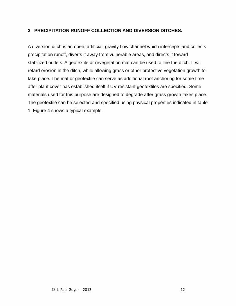
2.1.4 ANCHORAGE. At the toe of the streambank, the geotextile and cover material
should be placed along the bank to an elevation below mean low water level to
minimize erosion at the toe. Placement to a vertical distance of 3 feet below mean low
water level, or to the bottom of the streambed for streams shallower than 3 feet, is
recommended. At the top of the bank, the geotextile and cover material should either
be placed along the top of the bank or with 2 feet vertical freeboard above expected
maximum water stage. If strong water movements are expected, the geotextile needs to
be anchored at the crest and toe of the streambank (fig 2).
© J. Paul Guyer 2013 6

2.1.5 IF THE GEOTEXTILE must be placed below low water, a material of a density
greater than that of water should be selected.
Table 1
Recommended Geotextile Mininmum Strength Requirements.
2.2 CONSTRUCTION CONSIDERATIONS.
2.2.1 SITE PREPARATION. The surface should be cleared of vegetation, large stones,
limbs, stumps, trees, brush, roots, and other debris and then graded to a relatively
smooth plane free of obstructions, depressions, and soft pockets of materials.
© J. Paul Guyer 2013 7

2.2.2 PLACEMENT OF GEOTEXTILES. The geotextile is unrolled directly on the
smoothly graded soil surface. It should not be left exposed to UV deterioration for more
than 1 week in case of untreated geotextiles, and for more than 30 days in case of UV
protected and low UV susceptible polymer geotextiles. The geotextile should be loosely
laid, free of tension, folds, and wrinkles. When used for streambank protection, where
currents acting parallel to the bank are the principal erosion forces, the geotextile should
be placed with the longer dimension (machine direction) in the direction of anticipated
water flow. The upper strips of the geotextile should overlap the lower strips (fig 3).
When used for wave attack or cut and fill slope protection, the geotextile should be
placed vertically down the slope (fig 3), and the upslope strips should cover the
downslope strips. Stagger the overlaps at the ends of the strips at least 5 feet. The
geotextile should be anchored at its terminal ends to prevent uplift or undermining. For
this purpose, key trenches and aprons are used at the crest and toe of the slope.
2.2.3 OVERLAPS, SEAMS, SECURING PINS. Adjacent geotextile strips should have a
minimum overlap of 12 inches along the edges and at the end of rolls. For underwater
placement, minimum overlap should be 3 feet. Specific applications may require
additional overlaps. Sewing, stapling, heat
© J. Paul Guyer 2013 8

Figure 1
Relationship between Atterberg Limits and Expected Erosion Potential.
© J. Paul Guyer 2013 9
Table 2
Pin Spacing Requirements in Erosion Control Applications
welding, or gluing adjacent panels, either in the factory or on site, are preferred to
lapping only. Sewing has proved to be the most reliable method of joining adjacent
panels. It should be performed using polyester, polypropylene, kevlar or nylon thread.
The seam strength for both factory and field seams should not be less than 90 percent
of the required tensile strength of the unaged geotextile in any principal direction.
Geotextiles may be held in place on the slope with securing pins prior to placing the
cover material. These pins with washers should be inserted through both strips of the
overlapped geotextile along a line through the midpoint of the overlap. The pin spacing,
both along the overlaps or seams, depends on the slope, as specified in table 2. Steel
securing pins, 3/16 inch in diameter, 18 inches long, pointed at one end, and fitted with
a l.5-inch metal washer on the other have performed well in rather firm soils. Longer
pins are advisable for use in loose soils. The maximum slope on which geotextiles may
be placed will be determined by the friction angles between the natural-ground and
geotextile and cover- material and geotextile. The maximum allowable slope in no case
can be greater than the lowest friction angle between these two materials and the
geotextile.
© J. Paul Guyer 2013 10

2.2.4 PLACEMENT OF COVER MATERIAL ON GEOTEXTILE. For sloped surfaces,
placement of the cover stone or riprap should start from the base of the slope moving
upward and preferably from the center outward to limit any partial movement of soil
because of sliding. In no case should drop heights which damage the geotextile be
permitted. Testing may be necessary to establish an acceptable drop height.
© J. Paul Guyer 2013 11
3. PRECIPITATION RUNOFF COLLECTION AND DIVERSION DITCHES.
A diversion ditch is an open, artificial, gravity flow channel which intercepts and collects
precipitation runoff, diverts it away from vulnerable areas, and directs it toward
stabilized outlets. A geotextile or revegetation mat can be used to line the ditch. It will
retard erosion in the ditch, while allowing grass or other protective vegetation growth to
take place. The mat or geotextile can serve as additional root anchoring for some time
after plant cover has established itself if UV resistant geotextiles are specified. Some
materials used for this purpose are designed to degrade after grass growth takes place.
The geotextile can be selected and specified using physical properties indicated in table
1. Figure 4 shows a typical example.
© J. Paul Guyer 2013 12

4. MISCELLANEOUS EROSION CONTROL.
Figures 5 and 6 show examples of geotextile applications in erosion control at drop
inlets and culvert outlets and scour protection around bridges, piers, and abutments.
Design criteria similar to that used for bank protection should be used for these
applications.
© J. Paul Guyer 2013 13
Figure 2
Pin Spacing Requirements in Erosion Control Applications.
© J. Paul Guyer 2013 14
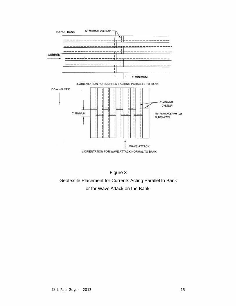
Figure 3
Geotextile Placement for Currents Acting Parallel to Bank
or for Wave Attack on the Bank.
© J. Paul Guyer 2013 15

5. SEDIMENT CONTROL. Silt fences and silt curtains are sediment control systems
using geotextiles.
5.1 SILT FENCE. A silt fence is a temporary vertical barrier composed of a sheet of
geotextile supported by fencing or simply by posts, as illustrated in figure 5. The lower
end of the geotextile is buried in a trench cut into the ground so that runoff will not flow
beneath the fence. The purpose of the permeable geotextile silt fence is to intercept and
detain sediment from unprotected areas before it leaves the construction site. Silt fence
are sometimes located around the entire downslope portion or perimeter of urban
construction sites. Short fences are often placed across small drainage ditches
(permanent or temporary) constructed on the site. Both applications are intended to
function for one or two construction seasons or until grass sod is established. The fence
reduces water velocity allowing the sediment to settle out of suspension.
5.1.1 DESIGN CONCEPTS. A silt fence consists of a sheet of geotextile and a support
component. The support component may be a wire or plastic mesh support fence
attached to support posts or in some cases may be support posts only. The designer
has to determine the minimum height of silt fences, and consider the geotextile
properties (tensile strength, permeability) and external factors (the slope of the surface,
the volume of water and suspended particles which are delivered to the silt fence, and
the size distribution of the suspended particles). Referring to figure 6-7, the total height
of the silt fence must be greater than h1 + h2 + h; where h1 the height of geotextile
necessary to allow water flowing into the basin to flow through the geotextile,
considering the permeability of the geotextile; is the height of water necessary to
overcome the threshold gradient of the geotextile and to initiate flow. For most expected
conditions, h1 + h2 is about 6 inches or less. The silt fence accomplishes its purpose by
creating a pond of relatively still water which serves as a sedimentation basin and
collects the suspended solids from the runoff. The useful life of the silt fence is the time
required to fill the triangular area of height
© J. Paul Guyer 2013 16
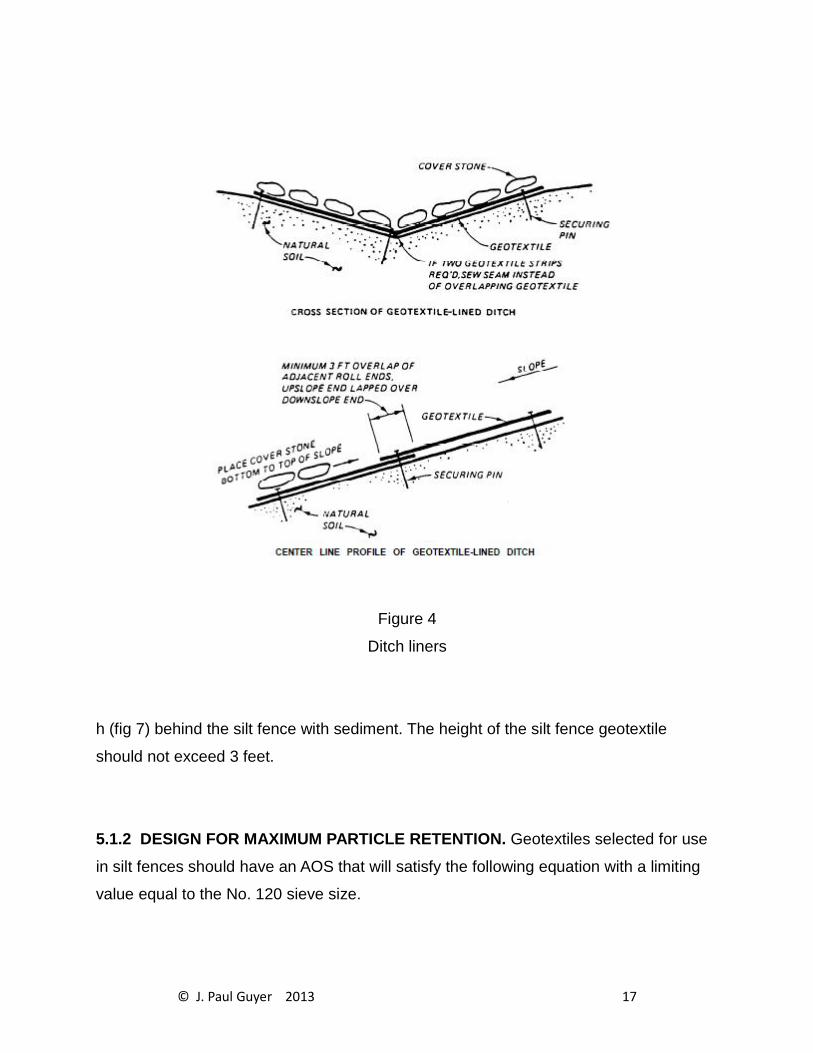
Figure 4
Ditch liners
h (fig 7) behind the silt fence with sediment. The height of the silt fence geotextile
should not exceed 3 feet.
5.1.2 DESIGN FOR MAXIMUM PARTICLE RETENTION. Geotextiles selected for use
in silt fences should have an AOS that will satisfy the following equation with a limiting
value equal to the No. 120 sieve size.
© J. Paul Guyer 2013 17

(Eq 1)
A minimum of 90-pound tensile strength (ASTM D 4632 Grab Test Method) is recommended for use with support posts spaced a maximum of 8 feet apart.
5.1.3 DESIGN FOR FILTRATION EFFICIENCY. The geotextile should be capable of
filtering most of the soil particles carried in the runoff from a construction site without
unduly impeding the flow. ASTM D 5141 presents the laboratory test used to determine
the filtering efficiency and the flow rate of the sediment-filled water through the
geotextile.
5.1.4 REQUIRED GEOTEXTILE PROPERTIES. The geotextile used for silt fence must
also have:
(a) Reasonable puncture and tear resistance to prevent damage by floating debris and
to limit tearing where attached to posts and fence.
(b) Adequate resistance to UV deterioration and biological, chemical, and thermal
actions for the desired life of the fence.
5.1.5 CONSTRUCTION CONSIDERATIONS.
(a) Silt fences should be constructed after the cutting of trees but before having any sod
disturbing construction activity in the drainage area.
© J. Paul Guyer 2013 18

(b) It is a good practice to construct the silt fence across a flat area in the form of a
horseshoe. This aids in the ponding of the runoff, and increases the strength of the
fence. Prefabricated silt fence sections containing geotextile and support posts are
commercially available. They are generally manufactured in heights of 18 and 36
inches. At the lower portion of the silt fence, the geotextile is extended for burying
anchorage.
5.2 SILT CURTAINS. A silt curtain is a floating vertical barrier placed within a stream,
lake, or other body of water generally at runoff discharge points. It acts as a temporary
dike to arrest and control turbidity. By interrupting the flow of water, it retains suspended
particles; by reducing the velocity, it allows sedimentation. A silt curtain is composed of
a sheet of geotextile maintained in a vertical position by flotation segments at the top
and a ballast chain along the bottom. A tension cable is often built into the curtain
immediately above or below the flotation segments to absorb stress imposed by
currents and other hydrodynamic forces. Silt curtain sections are usually about 100 feet
long and of any required width. An end connector is provided at each end of the section
for fastening sections together. Anchor lines hold the curtain in a configuration that is
usually U-shaped, circular, or elliptical. The design criteria and properties required for
silt fences also apply to silt curtains. Silt curtains should not be used for:
(1) Operations in open ocean.
(2) Operations in currents exceeding 1 knot.
(3) Areas frequently exposed to high winds and large breaking waves.
(4) Around hopper or cutterhead dredges where frequent curtain movement would be
necessary.
© J. Paul Guyer 2013 19

Figure 5
Use of Geotextiles near Small Hydraulic Structures
© J. Paul Guyer 2013 20

Figure 6
Use of Geotextiles around Piers and Abutments
© J. Paul Guyer 2013 21

Figure 7
Sedimentation behind Silt Fence.
© J. Paul Guyer 2013 22

6. REFERENCES
Al-Hussaini, M. M., �Field Experiment of Fabric Reinforced Earth Wall,� Proceedings of the International Conference on the Use of Fabrics in Geotechnics, Paris, Apr 20-22, Vol. 1, pp. 119-121, 1977.
Al-Hussaini, M., and Perry, E. B., �Analysis of A Rubber- Membrane Strip Reinforced
Earth Wall,� SoilReinforcing and Stabilizing Techniques in Engineering Practice,
Proceedings of a Symposium Jointly Organized by the New South Wales Institute of Technology and the University of New South Wales,Sydney, Australia, 1978.
Andrawes, K. Z., McGowan, A., Wilson-Fahmy, R. F., and Mashhour, M. M., �The Finite-
Element Method of Analysis Applied to Soil-Geotextile Systems,� Proceedings of the 2nd International Conference on Geotextiles, Las Vegas, Aug l-6, Vol. 3, pp. 695-700, 1982.
Baker, R., �Tensile Strength, Tension Cracks and Stability of Slopes,� Soils and Foundations, Journal of the Japanese Society of Soil Mechanics and Foundations Engineering, Vol. 21, No. 2, pp. 1-17, 1981.
Baker, R., and Garber, M., �Variational Approach to Slope Stability,� Proceedings of the 9th International Conference on Soil Mechanics and Foundation Engineering, Vol. 2, pp.9-12, Tokyo, 1977.
Baker, R., and Garber, M., �Theoretical Analysis of the Stability of Slopes,�
Geotechnique, Vol. 28, No. 4, pp. 395-411, 1978.
Barrett, R. K., �Geotextiles in Earth Reinforcement,� Geotechnical Fabrics Report, Mar/Apr, Vol. 3, No. 2, pp. 15-99, 1988.
Bell, J. R., Barrett, R. K., and Ruckman, A. C., �Geotextile Earth-Reinforced Retaining
Wall Tests: Glenwood Canyon, Colorado,� Transportation Research Record, 916, pp. 59-69, 1983.
Bell, J. R., Greenway, D. R., and Vischer, W., �Construction and Analysis of a Fabric-
Reinforced Low Embankment on Muskeg,� Proceedings, International Conference on the Use of Fabrics in Geotechniques, Paris, Vol. 1, pp. 71-76, 1977.
Bell, J. R., and Hicks, R. G., �Evaluation of Test Methods and Use Criteria for
Geotechnical Fabrics in Highway Applications, Final Report,� Federal Highway
Administration, Washington, DC, 1983.
Bell, J. R., and Steward, J. E., �Construction and Observation of Fabric Retained Soil
Walls,� Proceedings of the International Conference on the Use of Fabrics in Geotechnics, April 20-22, Vol. 1, pp. 123-128, 1977.
Bell, J. R., Stilley, A. N., and Vandre, B., �Fabric Retained Earth Walls,� Proceedings of the 13th Annual Engineering Geology and Soils Engineering Symposium, University of Idaho, Moscow, Idaho, April 2-4, pp. 271-287, 1975.
Blair, J. C., Bell, J. R., and Hicks, R. G., �Permeability Testing of Geotextiles,�
Transportation Research Record, 826, pp. 1-6, 1981.
© J. Paul Guyer 2013 23

Broms, B. B., �Design of Fabric Reinforced Retaining Structures,� Proceedings of the Symposium on Earth Reinforcement, American Society of Civil Engineers, Pittsburgh, Penn., 1978.
Campbell, D. H., et al., �Erosion Objective: Storm Water Drainage Channel Needs
Erosion Protection,� Geotechnical Fabrics Report, p. 20, 1985.
Cedergren, H. R., Seepage, Drainage, and Flownets, Wiley, New York, 1977.
Chassie, R. G., �Geotextile Retaining Walls: Some Case History Examples,� paper
prepared for presentation at the 1984 NW Roads and Streets Conference, Corvalis, Oreg., 1984.
Chen, W. F., Limit Analysis and Soil Plasticity, Elsevier Pub., Amsterdam, The Netherlands, 1975.
Christie, I. F., and E-Hadi, K. M., �Some Aspects of the Design of Earth Dams
Reinforced with Fabric,� Proceedings of the International Conference on the Use of Fabrics in Geotechnics, Paris, April 20-22, Vol. 1, pp. 99-103, 1977.
Christopher, B. R. 1983. �Evaluation of Two Geotextile Installations in Excess of a
Decade Old,� Transportation Research Record 916, National Academy of Sciences, Washington, DC, p 79-88.
Christopher, B. R., and Holtz, R. D., �Geotextile Engineering Manual,� Report No.
FHWA-TS-861203, STS Consultants Ltd, Northbrook, Ill under contract FHWA No. DTFH61-83-C-00094, 1984.
Civil Works Construction Guide Specification, No. CW 02215, �Plastic Filter Fabric,�
Department of the Army Corps of Engineers, Office of the Chief of Engineers, Washington, DC, 1986.
Couch, F. B., Jr., �Geotextile Applications to Slope Protection for the Tennessee-
Tombigbee Waterway Divide Cut,� Second International Conference on Geotextiles, Las
Vegas, Nev., 1982.
Coutermarsh, B. A. and G. Phetteplace, �Numerical Analysis of Frost Shields,� in Proceedings, American Society of Civil Engineers/Canadian Geotechnical Society Sixth International Cold Regions Specialty Conference, W. Lebanon, NH, February 26-28, 1991, p. 178-190.
Coutermarsh, B. A. and G. Phetteplace, �Analysis of Frost Shields Using the Finite
Element Method,� Seventh International Conference on Numerical Methods in Thermal Problems, Stanford, CA, Pineridge Press, Swansea, UK, p. 123-132.
De Ment, L. E., �Two New Methods of Erosion Protection for Louisiana,� Shore Beach, Vol. 45, No. 1, p. 8, 1977.
Douglas, G. E., �Design and Construction of Fabric-Reinforced Retaining Walls by New
York State,� Transportation Research Record, 872, pp. 32-37, 1982.
El-Fermaoui, A., and Nowatzki, E., �Effect of Confining Pressure on Performance of
Geotextiles in Soils,� Proceedings of the 2nd International Conference on Geotextiles, Las Vegas, Aug l-6, Vol. 3, pp. 799-804, 1982.
© J. Paul Guyer 2013 24
Engineering and Design, �Use of Geotextiles Under Riprap,� Engineer Technical Letter
No. 1110-2-286, Department of the Army, US Army Corps of Engineers, Washington, DC, 1984.
Ford, H. W., �Estimating the Potential for Ochre Clogging Before Installing Drains,�
Transactions of the American Society of Civil Engineers 25(6), pp. 1597-1600, 1982a.
Ford, H. W., �Some Fundamentals of Iron and Slime Deposition in Drains,� Proceedingsof the Second International Drainage Workshop, Washington, DC, pp. 207-212, 1982b.
Fowler, Jack, �Analysis of Fabric-Reinforced Embankment Test Section at Pinto Pass,
Mobile, Alabama,� thesis submitted in partial fulfillment of the requirements for the
degree of Doctor of Philosophy, Oklahoma State University, Stillwater, Okla., 1979.
Fowler, J., �Theoretical Design Considerations for Fabric-Reinforced Embankments,�
Proceedings of the 2nd International Conference on Geotextiles, Las Vegas, Aug l-6, Vol. 3, pp. 665-670, 1982.
Geotextiles and Geomembranes, T. S. Ingold, Ed., published by Elsevier Applied Science Publishers, Essex, England, containing articles on geotextiles and geomembranes, began publication in 1984.
Geotechnical Fabrics Report, Published by Industrial Fabrics Association International since 1981, St. Paul, Minn.
Giroud, J. P., �Filter Criteria for Geotextiles,� Proceedings of the Second International Conference on Geotextiles, Vol. I, pp. 103-108, 1982.
Gulden, W., and Brown, D., �Treatments for Reduction of Reflective Cracking of Asphalt
Overlays on Jointed-Concrete Pavements in Georgia,� Transportation Research Record916, Transportation Research Board, Washington, DC, 1983.
Haliburton, T. A., �Design of Test Section for Pinto Pass Dike, Mobile, Alabama,� Report
prepared by Haliburton Associates, Stillwater, Okla., under Contract No. DACW0l-78-C-0092, for US Army Engineer District, Mobile, Mobile, Ala., 1978.
Haliburton, T. A., �Evaluation of Construction Procedure for Fabric-Reinforced
Embankment Test Section, Pinto Pass, Mobile Harbor, Alabama,� conducted by
Haliburton Associates, Stillwater, Okla., under Contract No. DACW39-78-M-4002, for US Army Engineer Waterways Experiment Station, Vicksburg, Miss., 1979.
Haliburton, T. A., Anglin, C. C., and Lawmaster, J. D., �Selection of Geotechnical Fabrics
for Embankment Reinforcement,� School of Civil Engineering, Oklahoma State
University, Stillwater, Okla., 1978.
Haliburton, T. A., Fowler, J., and Langan, J. P., �Design and Construction of Fabric-
Reinforced Embankment Test Section at Pinto Pass, Mobile, Alabama,� Transportation Research Record, 249, pp. 27-34, Washington, DC, 1980.
Haliburton, T. A., Lawmaster, J. D., and King, J. J., �Potential Use of Geotechnical
Fabric in Airfield Runway Design,� Contract No. AFOSR79-00871, Air Force Office of
Scientific Research, School of Civil Engineering, Oklahoma State University, Stillwater, Okla., 1980.
© J. Paul Guyer 2013 25

Haliburton, T. A., Lawmaster, J. D., and McGuffie, V. C., �Use of Engineering Fabrics in
Transportation Related Applications,� Haliburton Associates Engineering Consultants,
Under Contract No. DTFH-80-C-0094, Stillwater, Okla., 1981.
Hammer, D. P., and Blackburn, E. D., �Design and Construction of Retaining Dikes for
Containment of Dredged Material,� Technical Report TR-D-77-9, US Army Engineer
District, Savannah, Savannah, Ga., 1977.
Henry, K. S., �Geotextiles as Capillary Barriers,� Geotechnical Fabrics Report, March/April, pp. 30-36.
Henry, K. S., �Laboratory Investigation of the Use of Geotextiles to Mitigate Frost
Heave,� CRREL Report 90-6, CRREL, Hanover, NH USA, 28 p.
Henry, K. S., �Use of Geotextiles to Mitigate Frost Heave in Soils,�, in Proceedings, V International Conference on Permafrost in Trondheim, Norway, Vol. 2, p. 1096-1011.
Henry, K. S., S. Taylor and J. Ingersoll, �Effects of Freezing on the Microstructure of
Two Geotextiles,� in Geosynthetics: Microstructure and Performance, ASTM STP 1076, pp. 147-164.
Henry, Karen S., �Effect of Geotextiles on Water Migration in Freezing Soils and the
Influence of Freezing on Performance,� Proceedings, Geosynthetics, 91, Atlanta, GA, Industrial Fabrics Association International, St. Paul, MN.
Horz, R. C., �Geotextiles for Drainage, Gas Venting, and Erosion Control at Hazardous
Waste Sites,� Report No. EPA/600/2-86/085, US Environmental Protection Agency, Cincinnati, Ohio, 1986.
Ingold, T. S., �An Analytical Study of Geotextile Reinforced Embankments,� Proceedingsof the 2nd International Conference on Geotextiles, Las Vegas, Aug l-6, Vol. 3, pp. 683-688, 1982.
Instruction for Use of Construction Specification No. 210, �Plastic Filter Cloth,�
Department of the Army Corps of Engineers, Office of the Chief of Engineers, Washington, DC, 1981.
Jewell, R. A., �A Limit Equilibrium Design Method for Reinforced Embankments of Soft
Foundations,� Proceedings of the 2nd International Conference on Geotextiles, Las Vegas, Aug l-6, Vol. 3.) pp. 671-676, 1982.
Jones, C. J. F. P., Earth Reinforcement and Soil Structures, Butterworth and Co., Ltd., London, 1985.
Keown, M. P., and Oswalt, N. R., �US Army Corps of Engineers Experience with Filter
Fabric for Streambank Protection Applications, Flexible Armored Revetments Incorporating Geotextiles,� Proceedings of the International Conference Organized by the Institution of Civil Engineers, London, 1984.
Koerner, R. M., Designing with Geosynthetics, Prentice-Hall, Englewood Cliffs, N.J., 1986.
Koerner, R. M., and Bove, J. A., �In-Plane Hydraulic Properties of Geotextiles,�
Geotechnical Testing Journal, Vol. 6, No. 4, pp. 190-195, 1983.
© J. Paul Guyer 2013 26
Koerner, R. M., and Welsh, J. P., Construction and Geotechnical Engineering Using Synthetic Fabrics,�Wiley, New York, 1980.
Lamb, T. W., and Whitman, R. V., Soil Mechanics, SI Version, Wiley, New York, 1979.
Lee, K. L., Adams, B. D., and Vagneron, J-M. J., �Reinforced Earth Retaining Walls,�
Journal of the Soil Mechanics and Foundations Division, American Society of Civil Engineers, Vol. 99, No. SM10, pp. 745-764, 1973.
Leshchinsky, D., �Geotextile Reinforced Earth, Part I & II,� Research Report Nos. CE
84-44/45, Department of Civil Engineering, University of Delaware, Newark, Del., 1984.
Leshchinsky, D., Baker, R., and Silver, M. L., �Three Dimensional Analysis of Slope
Stability,� International Journal for Numerical and Analytical Methods in Geomechanics, Vol. 9, pp. 199-223, 1985.
Leshchinsky, D., and Boedeker, R. H., �Geosynthetic Reinforced Soil Structures,�
Journal of the Geotechnical Engineering, American Society of Civil Engineers, Vol. 115, No. 10, pp. 1459-1478, 1989.
Leshchinsky, D., and Field, D. A., �In-Soil Load Elongation, Tensile Strength and
Interface Friction of Nonwoven Geotextiles,� Proceedings of the Geosynthetics �87
Conference, New Orleans, Feb 24-25, Vol. 1, pp. 238-249, 1987.
Leshchinsky, D., and Perry, E. B., �On the Design of Geosynthetic-Reinforced Walls,�
Geotextiles and Geomembranes, (in press), 1989.
Leshchinsky, D., and Reinschmidt, A. J., �Stability of Membrane Reinforced Slopes,�
Journal of the Geotechnical Engineering, American Society of Civil Engineers, Vol. 111, No. 11, pp. 1285-1300, 1985.
Leshchinsky, D., and Volk, J. C., �Stability Charts for Geotextile Reinforced Walls,�
Transportation Research Record, 1031, pp. 5-16, 1985.
McGhee, K. H., �Efforts to Reduce Reflective Cracking of Bituminous Concrete Overlays
of Portland Cement Concrete Pavements,� Virginia Highway and Transportation
Research �Council, Charlottesville, Va., 1975.
McGowan, A., Andrawes, K. Z., and Kabir, M. H., �Load-Extension Testing of Geotextiles
Confined In-Soil,� Proceedings of the 2nd International Conference on Geotextiles, Las Vegas, Aug l-6, Vol. 3, pp. 793-798, 1982.
Meyerhof, G. G., �The Bearing Capacity of Foundations Under Eccentric and Inclined
Loads,� Proceedings, 34th International Conference on Soil Mechanics and Foundation Engineering, Zurich, Vol. 1, pp. 440-445, 1953.
Mitchell, J. K., �Earth Walls,� Transportation News, Transportation Research Board, National Research Council, No. 114, pp. 24-31, 1984.
Mohney, J., �Fabric Retaining Wall-Olympic N. F.,� Highway Focus, Vol. 9, No. 1, pp. 88-103, 1977.
Murray, R. T., �Fabric Reinforced Earth Walls: Development of Design Equations,�
Ground Engineering, Vol. 13, No. 7, pp. 29-36, 1980.
© J. Paul Guyer 2013 27

Murray, R. T., �Fabric Reinforced Earth Walls: Development of Design Equations,�
Supplementary Report 496, Structures Department, Transport and Road Research Laboratory, Crowthorne, Berkshire, United Kingdom, 1981.
Murray, R., �Fabric Reinforcement of Embankments and Cuttings,� Proceedings of the 2nd International Conference on Geotextiles, Las Vegas, Aug l-6, Vol. 3, pp. 707-713, 1982.
Perloff, W. H., Pressure Distribution and Settlement, Chapter 4 in Foundation Engineering Handbook, ed. by Winterkorn and Fang, Van Nostrand Reinhold Company, New York, 1975.
Perloff, W. H., and Baron, W., Soil Mechanics: Principles and Applications, Wiley, 1976.
Proceedings, International Conference on the Use of Fabrics in Geotechnics, Ecole Nationale des Ponts et Chaussees, Paris, 3 Vol., 1977.
Proceedings of the First Canadian Symposium on Geotextiles (Calgary, Canada, Sep 1980), published by the Canadian Geotechnical Society, 700 EIC Bldg, 2050 Mansfield St., Montreal, Quebec, Canada, 1980.
Proceedings, Second International Conference on Geotextiles, Industrial Fabrics Association International, St. Paul, Minn., 4 Vol., 1982.
Rankilor, P. R., Membranes in Ground Engineering, Wiley, Chichester, United Kingdom, 1981.
Raymond, G. P., �Installation Factors that Affect Performance of Railroad Geotextiles,�
Transportation Research Record 1071, Transportation Research Board, Washington, DC, 1986.
Richards, D. L., and Middleton, L. M., �Best Management Practices for Erosion and
Sediment Control,� Federal Highway Administration, Arlington, Va., 1978.
Risseeuw, Ir. P., �Stabilenka Woven Reinforcement Fabric in Raising Mounds on Soft
Soil,� Report NO. R.O. 5300.005, Akzo Research Laboratories, Department, C.T.I.,
Arnhem, The Netherlands, 1977.
Rowe, R. K., �Reinforced Embankments: Analysis and Design,� Journal of the Geotechnical Engineering, American Society of Civil Engineers, Vol. 110, No. 2, pp. 231-246, 1984.
Sherard, J. L., �Sinkholes in Dams of Coarse, Broadly Graded Soils,� Thirteenth Conference of the International Congress on Large Dams, New Delhi, India, Vol. 2, pp. 25-35, 1979.
Shoop, S. A. and K. Henry, �The Effect of a Geotextile on Water Migration and Frost
Heave in Large-Scale Tests,� preprint 910532, Transportation Research Board, 70th Annual Meeting, January 13-17, 1991.
Spangler, M. G., Soil Engineering, International Textbook Company, New York, 1951.
Stilley, A. N., �A Model Study of Fabric Reinforced Earth Walls,� thesis submitted in
partial fulfillment of the requirements for the Degree of Master of Science to Oregon State University, Corvalis, Oreg., 64 pp., 1974.
© J. Paul Guyer 2013 28

Terzaghi, K., and Peck, R. B., Soil Mechanics in Engineering Practice, 2nd Ed., Wiley, New York, 1967.
US Department of Transportation, �Sample Specifications for Engineering Fabrics,�
FHWA Report TS-78-211, Federal Highway Administration, Washington, DC, 1978.
Van Zanten, R. V., Geotextiles and Geomembranes in Civil Engineering, A. A. Balkema, Rotterdam, The Netherlands, 1986.
Volk, J. C., �Analysis and Design of Geotextile Reinforced Walls,� thesis submitted in
partial fulfillment of the requirements for the Degree of Master of Civil Engineering to theFaculty of the University of Delaware, Newark, Del., 1984.
Weimar, R. D., Jr., �Mechanism of the Geotextile Performance in Soil-Fabric Systems
for Drainage and Erosion Control,� Transportation Research Record No. 916, pp. 37-40,Transportation Research Board, 1983.
Winterkorn, H. F., and Fang, H-Y, Foundation Engineering Handbook, Van Nostrand Reinhold Company, New York, 1975.
Wyant, David C., �Evaluation of Filter Fabrics for Use as Silt Fences,� Report No.
VHTRC 80-R49, Virginia Highway and Transportation Research Council, Charlottesville,Va., 1980.
© J. Paul Guyer 2013 29

QUIZ
An Introduction to Geotextiles in Erosion Control
1. For _____________ , placement of the cover stone or riprap should start from the baseof the slope moving upward and preferably from the center outward to limit any partial movement of soil because of sliding.
a. vegetated areasb. channel bottomsc. sloped surfacesd. slopes on cohesionless soils
2. A diversion ditch is an open, artificial, gravity flow channel which intercepts and collectsprecipitation runoff, diverts it away from vulnerable areas, and directs it toward stabilized outlets. A geotextile or _______________ can be used to line the ditch.
a. grout matb. bond layerc. compacted sand layerd. revegetation mat
3. A/an ____________ is a temporary vertical barrier composed of a sheet of geotextile supported by fencing or simply by posts.
a. wall capb. erosion wallc. silt fenced. overtopping
4. A _______________ is a floating vertical barrier placed within a stream, lake, or other body of water generally at runoff discharge points.
a. coffer damb. silt curtainc. geotextile weird. beaver dam
5. Geotextiles are used as a separation layer between the streambed soil and rip-rap placed for _____________ around bridge piers.
a. scour protectionb. sediment collectionc. ballastd. erosion enhancement
6. Riprap is used as a liner for ditches and channels subjected to high-velocity flow and for lake, reservoir and channel banks subject to wave action. ___________ is/are an effective and economical alternative to conventional graded filters under stone riprap.
a. Hydroseedingb. Stabilized sandc. Soil amendmentsd. Geotextiles
7. All geotextile specifications must include a provision for covering the geotextile to limit its ________________ exposure to 30 days or less.
a. low temperatureb. weatherc. saline waterd. ultraviolet radiation
8. The ______________ (gravel, rock fragments, riprap, armor stone, concrete blocks, etc.) is a protective covering over the geotextile that minimizes or dissipates the hydraulic forces, protects the geotextile from extended exposure to UV radiation, and keeps it in intimate contact with the soil.
a. weathering surfaceb. cover materialc. slope enveloped. graded layer
9. At the toe of the streambank, the geotextile and cover material should be placed along the bank to an elevation below mean low water level ______________ at the toe.
a. cross drainsb. gradientc. to improve soil pumpingd. to minimize erosion

10. At the top of the bank, the geotextile and _____________ should either be placed along the top of the bank or with 2 feet vertical freeboard above expected maximum water stage.
a. stabilized sand drainb. geonetc. cover materiald. topping
11. The geotextile is unrolled directly on the smoothly graded soil surface. It should not beleft exposed to UV deterioration for more than ___________ week(s) in case of untreated geotextiles.
a. 1b. 2c. 3d. 4
12. The geotextile should be loosely laid, free of tension, folds, and wrinkles. When used for streambank protection, where currents acting parallel to the bank are the principal erosion forces, the geotextile should be placed with the longer dimension (machine direction) in the direction of anticipated water flow. The upper strips of the geotextile should overlap the lower strips. When used for wave attack or cut and fill slope protection, the geotextile should be placed vertically down the slope, and the upslope strips should cover the downslope strips. Stagger the overlaps at the ends of the strips at least ______ feet.
a. 15b. 10c. 5d. 3
13. Prior to start of construction the surface to be protected should be ______________________ .
a. cleared of vegetationb. treated to stabilize the soilc. pumped to lower the water table below the channel bottomd. compacted to 90% or greater of ASTM 356 density

14. Adjacent geotextile strips should have a minimum overlap of __________ inches along the edges and at the end of rolls.
a. 12b. 18c. 24d. 36
15. For geotextiles placed on slopes steeper than 1-vertical on 3-horizontal, minimum anchorage pin spacing is ________________ feet.
a. 5b. 4c. 3d. 2