Embed Size (px)
Citation preview

Offices Nationwide
Employee - Owned
Geotechnical
Established in 1965
terracon .com lrerracan Environmental ■ Construction Materials Facilities
Geotechnical Engineering Report South Florida National Cemetery
6501 State Road 7 Lake Worth, Palm Beach County, Florida
January 19, 2018 Terracon Project No. HD165118
Prepared for: Mabbett & Associates, Inc. Providence, Rhode Island
Prepared by: Terracon Consultants, Inc. West Palm Beach, Florida

lrerracon
Geotechnical ■ Environmental ■ Construction Materials ■ Facilities
January 19, 2018
Mabbett & Associates, Inc. 10 Dorrance Street, Suite 700 Providence, RI 02903
Attn: Andrew Glucksman, LEED AP Project Manager Email: [email protected] Phone: 781.275.6050 ext. 401
Re: Geotechnical Engineering Report South Florida National Cemetery Expansion 6501 State Road 7 Lake Worth, Palm Beach County, Florida
Project Number: HD165118
Terracon Consultants, Inc. (Terracon) has completed the geotechnical engineering study for the above referenced project. This study was performed in general accordance with the Subcontract Agreement dated October 21, 2016.
This report presents the findings of the subsurface exploration and provides geotechnical recommendations concerning earthwork and the design and construction of foundations for the proposed project.
We appreciate the opportunity to be of service to you on this project. If you have any questions concerning this report, or if we may be of further service, please contact us.
Sincerely, Terracon Consultants, Inc. Certificate of Authorization Number 8830
Daniel J. Marieni, P.E. Kevin E. Aubry, P.E. Geotechnical Department Manager Senior Geotechnical Engineer FL Registration No. 78629 FL Registration No. 38175
Terracon Consul tants, Inc. 5463 W. Waters Avenue, Sui te 830 Tampa, FL 33634 P [813] 221-0050 F [813] 221-0051 terracon.com

1.0 2.0
3.0
4.0
5.0
4.2.1 4.2.2 4.2.3 4.2.4 4.2.5 4.2.6
4.3.1 4.3.2
4.5.1 4.5.2
4.6.1 4.6.2 4.6.3 4.6.4 4.6.5 4.6.6
TABLE OF CONTENTS
EXECUTIVE SUMMARY ............................................................................................................. i INTRODUCTION ............................................................................................................. 1 PROJECT INFORMATION ............................................................................................. 1 2.1 Project Description ............................................................................................... 1 2.2 Site Location and Description............................................................................... 2 SUBSURFACE CONDITIONS ........................................................................................ 2 3.1 Soil Survey........................................................................................................... 2 3.2 Typical Profile ...................................................................................................... 3 3.3 Groundwater ........................................................................................................ 3 3.4 Percolation Tests ................................................................................................. 5 3.5 Laboratory Test Results ....................................................................................... 6 RECOMMENDATIONS FOR DESIGN AND CONSTRUCTION ...................................... 7 4.1 Geotechnical Considerations ............................................................................... 7 4.2 Earthwork............................................................................................................. 7
Site Preparation........................................................................................ 7 Material Requirements ............................................................................. 8 Compaction Requirements-Mass Fill Areas .............................................. 8 Utility Trench Backfill ................................................................................. 9 Grading and Drainage .............................................................................. 9 Earthwork Construction Considerations .................................................... 9
4.3 Foundations ....................................................................................................... 10 Foundation Design Recommendations ................................................... 10 Foundation Construction Considerations ................................................ 11
4.4 Seismic Considerations...................................................................................... 12 4.5 Floor Slabs......................................................................................................... 12
Floor Slab Design Recommendations .................................................... 12 Floor Slab Construction Considerations.................................................. 13
4.6 Pavements ......................................................................................................... 13 Subgrade Preparation ............................................................................ 13 Design Considerations ........................................................................... 14 Estimates of Minimum Pavement Thickness ............................................ 14 Asphaltic Concrete Design Recommendations ....................................... 14 Pavement Drainage ................................................................................ 15 Pavement Maintenance .......................................................................... 15
4.7 Temporary Dewatering....................................................................................... 16 GENERAL COMMENTS ............................................................................................... 16
Responsive ■ Resourceful ■ Reliable

TABLE OF CONTENTS (continued)
APPENDIX A – FIELD EXPLORATION Exhibit A-1 Site Location Map Exhibit A-2 Soil Survey Exhibit A-3 Soil Survey Descriptions Exhibit A-4 Exploration Plan Exhibit A-5 Field Exploration Description Exhibit A-6-1 to A-6-15 Boring Logs
APPENDIX B – SUPPORTING INFORMATION Exhibit B-1 Laboratory Testing Exhibit B-2 Summary of Laboratory Test Results Exhibit B-3 Corrosion Test Results Exhibit B-4-1 to B-4-5 Grain Size Distribution Curves
APPENDIX C – SUPPORTING DOCUMENTS Exhibit C-1 General Notes Exhibit C-2 Unified Soil Classification System
Responsive ■ Resourceful ■ Reliable

lrerracon Geotechnical Engineering ReportSouth Florida National Cemetery Expansion ■ Lake Worth, Florida January 19, 2018 ■ Terracon Project No. HD165118
EXECUTIVE SUMMARY
A geotechnical exploration study has been performed for the proposed South Florida National Cemetery Expansion that is located in Lake Worth, Palm Beach County, Florida. Fifteen SPT borings, designated B-1 through B-15 were drilled to 15 feet below the existing ground surface and fifteen permeability tests were executed in the surficial soils (i.e. upper 2 feet below the existing ground surface) in the proposed expansion area.
Based on the information obtained from our geotechnical exploration, it appears that the site can be developed for the proposed project. The following geotechnical considerations were identified:
• The generalized subsurface profile consists of granular soils (i.e. sands) over a formation of weakly to moderately well cemented shellrock.
• Groundwater was found to be relatively shallow at the site, and some areas of ponding above the ground surface were observed. It is recommended that careful consideration be given to high groundwater levels when preparing the grading plan.
• The proposed columbariums may be supported on conventional shallow foundations bearing on compacted native soil or on newly placed engineered fill following the earthwork operations outlined in Section 4.2.
• It is anticipated that excavations for the proposed construction can be accomplished with conventional earthmoving equipment. However, excavations within the shellrock formation may be difficult and slow due to the hardness of the rock in some areas. Although the borings drilled at the site indicate that the rock is weakly to moderately well cemented, our regional experience suggests that the shellrock may be very hard in some areas.
• Close monitoring of the construction operations discussed herein will be critical in achieving the design subgrade support. We therefore recommend that Terracon be retained to monitor this portion of the work.
This summary should be used in conjunction with the entire report for design purposes. It should be recognized that details were not included or fully developed in this section, and the report must be read in its entirety for a comprehensive understanding of the items contained herein. The section titled GENERAL COMMENTS should be read for an understanding of the report limitations.
Responsive ■ Resourceful ■ Reliable i

1.0
2.0
GEOTECHNICAL ENGINEERING REPORT PROPOSED FLORIDA NATIONAL CEMETERY EXPANSION
6501 State Road 7 Lake Worth, Palm Beach, Florida
Terracon Project No. HD165118 January 19, 2018
INTRODUCTION
A geotechnical engineering study has been prepared for the proposed expansion of the South Florida National Cemetery in Lake Worth, Palm Beach County, Florida. Fifteen SPT borings, designated B-1 through B-15, were drilled to about 15 feet below the existing ground surface in the proposed expansion areas. Fifteen permeability tests were conducted adjacent to selected boring locations. A Site Location Map and Exploration Plan are included in Appendix A as Exhibits A-1 and A-4, respectively. Logs of the test borings are also included in Appendix A.
The purpose of these services was to provide information and geotechnical engineering recommendations relative to:
• subsurface soil conditions • groundwater conditions • earthwork considerations • foundation design parameters • settlement estimates • related construction considerations
PROJECT INFORMATION
2.1 Project Description
Item Description
Boring layout See Appendix A, Exhibit A-4: Exploration Plan.
Proposed Construction The expansion will include the construction of columbariums and the development of additional gravesites to the north of the existing cemetery.
Building construction Masonry load bearing walls.
Maximum loads (assumed) Load bearing walls: 1 - 2 kips per lineal foot vertical load
Grading Significant thickness of earth fill will be placed to elevate the site to proposed grades.
Stormwater Management Not noted in this expansion.
Should any of the above information or assumptions be inconsistent with the planned construction, please let us know so that we may make any necessary modifications to this report.
Responsive ■ Resourceful ■ Reliable 1

lrerracon
3.0 SUBSURFACE CONDITIONS
3.1 Soil Survey
Geotechnical Engineering ReportSouth Florida National Cemetery Expansion ■ Lake Worth, Florida January 19, 2018 ■ Terracon Project No. HD165118
2.2 Site Location and Description
Item Description
Location
The Florida National Cemetery is located at 6501 State Road 7 in Lake Worth, Palm Beach County, Florida. The proposed expansion area is located to the north of the existing cemetery. The approximate center of the expansion area has the following coordinates: Latitude: 26°35'2.82"N Longitude: 80°12'38.92"W
Existing improvements The expansion area is currently undeveloped.
Current ground cover The expansion area is thickly vegetated by trees with underbrush.
Existing topography The existing topography appears to be relatively flat, with some slightly rolling and depressional areas scattered throughout.
The Soil Survey of Palm Beach County, Florida, issued 1978, as prepared by the United States Department of Agriculture (USDA), Soil Conservation Service (now renamed the Natural Resource Conservation Service - NRCS) was reviewed for the project area. The maps indicate that the site is underlain by Boca fine sand, with the exception of a few small pockets which are underlain by Riviera fine sand, depressional.
Boca fine sand is described as a nearly level, poorly drained soil that has a sandy subsurface that is underlain by a loamy subsoil from about 29 to 36 inches deep. Fractured limestone follows the loamy subsoil. The water table is within 10 inches of the natural ground surface for 2 to 4 months of the year.
Riviera fine sand, depressional is a nearly level, poorly drained soil with a thin sandy layer that is typically 3 inches thick. A loamy subsoil follows and is underlain by sand with shell fragments. For more than 6 months in a year the soil is ponded with up to 2 feet of water.
It should be noted that the Soil Survey is not intended as a substitute for site-specific geotechnical exploration; rather it is a useful tool in planning a project scope in that it provides information on soil types likely to be found. Boundaries between adjacent soil types on the Soil Survey map are approximate and are shown in Appendix A as Exhibit A-2. Descriptions of the mapped soil unit is included in Appendix A as Exhibit A-3.
Responsive ■ Resourceful ■ Reliable 2

lrerracon Geotechnical Engineering ReportSouth Florida National Cemetery Expansion ■ Lake Worth, Florida January 19, 2018 ■ Terracon Project No. HD165118
3.2 Typical Profile
Based on the results of the borings, subsurface conditions at the expansion area can be generalized as follows:
Stratum Approximate
Depth to Bottom of Stratum
Material Description Density/
Cementation
1 2 to 8 feet Fine SAND, sometimes with silt or clay,
sometimes with shell fragments (SP, SP-SM, SP-SC)
Loose to Medium Dense
2 4 to 7 feet Clayey SAND (SC) Medium Dense to Dense
3 8 to 15 feet Sandy SHELLROCK Weakly to
Moderately Well Cemented
4 15 feet SAND with silt, with varying amounts of shell fragments, sometimes with cemented sand
fragments (SP-SM) Loose to Dense
Conditions found at each boring location are indicated on the individual boring logs, which can be found on Exhibits A-6-1 through A-6-15 in Appendix A. Stratification boundaries on the boring logs represent the approximate location of changes in soil types; in-situ, the transition between materials may be gradual. Descriptions of our field exploration methods are included as Exhibit A-5 in Appendix A.
3.3 Groundwater
The boreholes were observed during drilling (December 14 through 20, 2017) for the presence and level of groundwater. Groundwater depths recorded during drilling ranged between 2 and 3 feet below the existing ground surface. Stabilized groundwater readings were collected at the locations of B-1, B-4, B-11 and B-13 on January 5, 2017 and ranged between 0.8 and 1.9 feet below surface grades. Additionally, some areas of the site were ponded above the ground surface during our field exploration. The following photograph shows an area of the site that was ponded.
Responsive ■ Resourceful ■ Reliable 3

lrerracon Geotechnical Engineering ReportSouth Florida National Cemetery Expansion ■ Lake Worth, Florida January 19, 2018 ■ Terracon Project No. HD165118
Photograph 1 – View of ponded area
It should also be noted that these borings were accomplished approximately one to two months after the end of the “wet season” when rainfall and recharge of the surficial aquifer is relatively high. Therefore, we would anticipate that the groundwater levels measured for this study would be slightly below the seasonal high levels.
It should be recognized that fluctuations of the groundwater table will occur due to seasonal variations in the amount of rainfall, runoff and other factors not evident at the time the borings were drilled. In addition, perched water can develop within higher permeability soils overlying less permeable soils. Therefore, groundwater levels during construction or at other times in the future may be higher or lower than the levels indicated on the boring logs.
We estimate the seasonal high water to range between one foot below the existing ground surface to at or above the existing ground surface, depending on topography. Our estimates of the seasonal groundwater conditions are based on the soil types found in the borings, recent weather conditions, and the water levels observed during our fieldwork. To obtain a better estimate of the seasonal high groundwater table, it would be necessary to install monitor wells and to take reading during the rainy season that generally runs from May to October.
These seasonal groundwater table estimates do not represent the temporary rise in groundwater table that occurs immediately during a significant storm event, including adjacent to other stormwater management facilities. This is different from static groundwater levels in wet ponds and/or drainage canals which can affect the design water levels of new, nearby ponds. The seasonal high groundwater table may vary from normal when affected by extreme weather changes, localized or regional flooding, future grading, drainage improvements, or other construction that may occur on our around the site following the date of this report.
Responsive ■ Resourceful ■ Reliable 4

lrerracon Geotechnical Engineering ReportSouth Florida National Cemetery Expansion ■ Lake Worth, Florida January 19, 2018 ■ Terracon Project No. HD165118
3.4 Percolation Tests
Percolation tests were conducted adjacent to each boring location. All of the tests were conducted at a depth of 2 feet. The tests were to be completed by excavating a 15 gallon (2 cubic foot) hole and introducing water into the hole and measuring the drawdown. However, the near surface soils were fine sands and thus the sides of the holes would not remain stable, especially with the high groundwater levels. As a result, the test was conducted using a 2-foot length of 4-inch diameter screened PVC pipe, filling the pipe with water, and measuring the water level drop (i.e. head drop) with time within the pipe. These results are presented in the following table, including depth to groundwater measured in the pipe, head drop and the permeability rates:
Permeability Test Results (Total Test)
Boring Number
Depth to groundwater
(inches)
Head Drop
(inches)
Time (minutes)
Permeability (cm/sec)
Permeability (inches/minute)
Soil Types
B-1 >24 21.0 30 5.6 x 10⁻⁴ 0.013 Find sand
B-2 >24 17.2 13 7.8 x 10⁻⁴ 0.018 Fine sand with clay
B-3 >24 19.8 30 4.7 x 10⁻⁴ 0.011 Find sand
B-4 >24 21.2 30 5.8 x 10⁻⁴ 0.014 Fine sand with silt
B-5 >24 21.0 30 5.6 x 10⁻⁴ 0.013 Fine sand
B-6 >24 22.9 30 8.3 x 10⁻⁴ 0.020 Fine sand
B-7 >24 19.2 30 4.3 x 10⁻⁴ 0.010 Fine sand with silt
B-8 >24 23.3 12 2.4 x 10⁻³ 0.056 Fine sand with silt
B-9 19 12.2 30 1.9 x 10⁻⁴ 4.5 x 10⁻³ Fine sand
B-10 >24 21.7 30 6.3 x 10⁻⁴ 0.015 Fine sand
B-11 23 1.8 30 2.1 x 10⁻⁵ 5.0 x 10⁻⁴ Fine sand with silt
B-12 10 7.7 30 1.0 x 10⁻⁴ 2.4 x 10⁻³ Fine sand
B-13 23 17.4 30 3.5 x 10⁻⁴ 8.2 x 10⁻³ Fine sand
B-14 >24 5.5 30 7.0 x 10⁻⁵ 1.7 x 10⁻³ Fine sand
B-15 >24 20.4 20 7.7 x 10⁻⁴ 0.018 Topsoil (6”) over fine sand (24”)
The initial drawdown during the tests was typically faster than the overall drawdown. The following table shows the permeability rates after the first five minutes of the tests.
Responsive ■ Resourceful ■ Reliable 5

lrerracon Geotechnical Engineering ReportSouth Florida National Cemetery Expansion ■ Lake Worth, Florida January 19, 2018 ■ Terracon Project No. HD165118
Permeability Test Results (First 5 Minutes of Test)
Boring Number
Depth to groundwater
(inches)
Head Drop
(inches)
Time (minutes)
Permeability (cm/sec)
Permeability (inches/minute) Soil Types
B-1 >24 13.0 5 1.3 x 10⁻³ 0.030 Find sand
B-2 >24 11.4 5 1.0 x 10⁻³ 0.025 Fine sand with clay
B-3 >24 10.4 5 9.2 x 10⁻³ 0.022 Find sand
B-4 >24 14.0 5 1.4 x 10⁻³ 0.034 Fine sand with silt
B-5 >24 13.7 5 1.4 x 10⁻³ 0.032 Fine sand
B-6 >24 15.6 5 1.7 x 10⁻³ 0.040 Fine sand
B-7 >24 11.6 5 1.1 x 10⁻³ 0.025 Fine sand with silt
B-8 >24 18.6 5 2.4 x 10⁻³ 0.057 Fine sand with silt
B-9 19 7.2 5 5.8 x 10⁻⁴ 0.014 Fine sand
B-10 >24 13.0 5 1.3 x 10⁻³ 0.030 Fine sand
B-11 23 0.5 5 3.3 x 10⁻⁵ 7.7 x 10⁻⁴ Fine sand with silt
B-12 10 4.7 5 3.5 x 10⁻⁴ 8.3 x 10⁻³ Fine sand
B-13 23 11.0 5 9.9 x 10⁻⁴ 0.023 Fine sand
B-14 >24 1.7 5 1.2 x 10⁻⁴ 2.8 x 10⁻³ Fine sand
B-15 >24 11.8 5 1.1 x 10⁻³ 0.026 Topsoil (6”) over fine sand (24”)
3.5 Laboratory Test Results
Soil index tests were conducted on selected representative soil samples. Grain size tests indicated that the clayey sands had fines contents between about 13 and 16 percent and that the shellrock was very sandy. The results of the tests are shown on the boring logs in Appendix A, are presented in tabular form in Appendix B (Exhibit B-2), and grain size curves are provided on Exhibits B-4-1 through B-4-5 for those soils where full grain size tests were conducted.
In addition, corrosion series testing including pH, chlorides, sulfates and resistivity were conducted on composite soil samples between the depths of 2 and 8 feet at the locations of Borings B-4 and B-8. The samples were also tested for redox potential. Using the FDOT criteria, the results of these tests indicate that the soils at this site are considered to be slightly aggressive for concrete and slightly to moderately aggressive for steel based on the resistivity values.
Responsive ■ Resourceful ■ Reliable 6

Geotechnical Engineering ReportSouth Florida National Cemetery Expansion ■ Lake Worth, Florida January 19, 2018 ■ Terracon Project No. HD165118
4.0 RECOMMENDATIONS FOR DESIGN AND CONSTRUCTION
4.1 Geotechnical Considerations
The results of the borings showed that the surficial soils are generally loose to medium dense clean to slightly silty/clayey sands. These soils can be used in the proposed construction and will provide adequate bearing, after proper site preparation. Clayey sands were found below the surficial sands in some areas. They should not be used as fill material as they will be very difficult to compact due to a very tight moisture range to obtain the required density. Sandy, weakly to moderately well cemented shellrock was found below the surficial sands, starting at depths between 2 and 8 feet below surface grades. It is anticipated that excavation within the shellrock can be accomplished with conventional earthmoving equipment, however the excavation may be difficult and slow due to the hardness of the rock in some areas. Groundwater was found to be relatively shallow at the site, and some areas of ponding above the ground surface were observed. It is recommended that careful consideration be given to high groundwater levels when preparing the grading plan.
We recommend that the exposed subgrade be thoroughly evaluated after removal of any surficial organics and vegetation prior to the start of site grading fill or structural fill operations. We recommend that Terracon be retained to evaluate the satisfactory preparation of the bearing material for the pavements, foundations, and floor slab subgrade soils. Subsurface conditions, as identified by the field and laboratory testing programs, have been reviewed and evaluated with respect to the proposed building plans known to us at this time.
Design and construction recommendations for foundation systems and other earth connected phases of the project are outlined below.
4.2 Earthwork
4.2.1 Site PSurface veget
reparation ation should be cleared from all areas receiving fill, structures and paving and its
root systems grubbed from the soils. Clearing and grubbing should consist of the complete removal and disposal of timber, stumps, roots, asphalt, concrete, rubbish, debris and all other obstructions resting on or protruding through the surface of the existing ground and the surface of excavated areas. All roots greater than one inch in diameter, or high concentrations of smaller diameter roots, exposed by clearing, grubbing and stripping should be removed to a depth of not less than 12 inches. Stripping depths between our boring locations and across the site could vary considerably, and as such we recommend actual stripping depths be evaluated by a representative of Terracon during construction to aid in preventing removal of excess material. Considering groundwater levels measured during this study and the potential for higher groundwater level conditions to occur during the wet season, we recommend that the project schedule be established such that the site preparation work is completed during the dry season, which typically extends from November to April.
Responsive ■ Resourceful ■ Reliable 7

Geotechnical Engineering Report South Florida National Cemetery Expansion ■ Lake Worth, Florida January 19, 2018 ■ Terracon Project No. HD165118
After stripping, proof-rolling should be performed with a vibratory roller with a minimum static weight of 20,000 pounds. Considering the shallow groundwater at the site, compaction may be difficult at the stripped grades. Therefore, a 1 to 2-foot thick layer of structural (or site grading) fill may need to be placed on top of the stripped grades prior to compaction. The roller should make a minimum of 10 overlapping passes over all areas of the proposed building and pavement areas and to 5 feet outside of the structural footprints. The latter 5 passes should be at right angle to previous passes. Rolling should continue until the soils are compacted sufficiently to obtain a minimum compaction as defined in Section 4.2.3. A geotechnical engineer or his representative should observe proof-rolling to aid in locating unstable subgrade materials (if any). Unstable soil (pumping) should be removed or moisture conditioned and compacted in place prior to placing fill. The excavated soils can then be used as backfill placed in accordance with the guidelines noted in Section 4.2.3 of this report.
Material Requirements Engineered fill should meet the following material property requirements:
Fill Type USCS Classification Acceptable Location for Placement
General 1
SP, SP-SM, SP-SC or GP, GP-GM (fines content < 12 percent, maximum
particle size < 2 inches, organic content < 2 percent)
All locations and elevations
1. The soils for Stratum 1 should meet these criteria. 2. Stratum 2 soils do not meet this criteria.
Compaction Requirements-Mass Fill Areas ITEM DESCRIPTION
Fill Lift Thickness
12 inches or less in loose thickness when heavy vibratory compaction equipment is used. Maximum particle size should not exceed 2 inches in a 12-inch lift. 4 to 6 inches in loose thickness when hand-guided equipment (i.e. jumping jack or plate compactor) is used. Maximum particle size should not exceed 1 inch in a 4- to 6-inch lift.
Minimum CompactionRequirements
Beneath the columbarium footprint and more than one foot below pavement subgrade elevation should be compacted to at least 95 percent of the maximum dry density as determined by the modified Proctor Test (ASTM D-1557). The upper one foot of pavement subgrades should be compacted to at least 98 percent of the maximum dry density as determined by the modified Proctor Test (ASTM D-1557). In the area of gravesites, the density requirement can be reduced to 90 percent of the maximum dry density as determined by the modified Proctor Test (ASTM D-1557).
Moisture Content 1 Within ±3 percent of optimum moisture content as determined by the modified Proctor test, at the time of placement and compaction.
Responsive ■ Resourceful ■ Reliable 8

lrerracon
4.2.4
4.2.5
4.2.6
1
Geotechnical Engineering ReportSouth Florida National Cemetery Expansion ■ Lake Worth, Florida January 19, 2018 ■ Terracon Project No. HD165118
One field density test per 2,500 square feet of building footprint (or Minimum Testing Frequency fraction thereof) per lift and one test per 5,000 square feet of
parking/drive area. We recommend that engineered fill be tested for moisture content and compaction during placement. Should the results of the in-place density tests indicate compaction limits have not been met, the area represented by the test should be reworked and retested as required until the compaction requirements are achieved.
Utility Trench Backfill All trench excavations should be made with sufficient working space to permit construction including backfill placement and compaction. The density of the backfill material should be checked and comply with the criteria noted in Section 4.2.3.
Grading and Drainage Final surrounding grades should be sloped away from the structures on all sides to prevent ponding of water. Gutters, downspouts, or other appropriate methods that direct water a minimum of 10 feet beyond the footprint of the proposed structures are recommended. Site grades should be set considering the estimated seasonal high groundwater presented in Section 3.4.
Earthwork Construction Considerations It is anticipated that excavations for the proposed construction can be accomplished with conventional earthmoving equipment. However, excavations within the shellrock formation may be difficult and slow due to the hardness of the rock in some areas. Although the borings drilled at the site indicate that the rock is weakly to moderately well cemented, our regional experience suggests that the shellrock may be very hard in some areas.
After initial proof-rolling and compaction, unstable subgrade conditions could develop during general construction operations, particularly if the soils are wetted and/or subjected to repetitive construction traffic. Upon completion of filling and grading, care should be taken to maintain the subgrade moisture content prior to construction of structures and pavements. Construction traffic over the completed subgrade should be avoided to the extent practical. The site should also be graded to prevent ponding of surface water on the prepared subgrades or in excavations. If the subgrade should become saturated, or disturbed, the affected material should be removed or these materials should be moisture conditioned and re-compacted prior to slab and pavement construction.
Trees or other vegetation whose root systems have the ability to remove excessive moisture from the subgrade and foundation soils should not be planted next to the structures. Trees and shrubbery should be kept away from the exterior edges of the foundation element a distance at least equal to 1.5 times their expected mature height.
Responsive ■ Resourceful ■ Reliable 9

lrerracon
4.3.1
Geotechnical Engineering ReportSouth Florida National Cemetery Expansion ■ Lake Worth, Florida January 19, 2018 ■ Terracon Project No. HD165118
As a minimum, all temporary excavations should be sloped or braced as required by Occupational Health and Safety Administration (OSHA) regulations to provide stability and safe working conditions. Temporary excavations will probably be required during grading operations. The grading contractor, by his contract, is usually responsible for designing and constructing stable, temporary excavations and should shore, slope or bench the sides of the excavations as required, to maintain stability of both the excavation sides and bottom. All excavations should comply with applicable local, state and federal safety regulations, including the current OSHA Excavation and Trench Safety Standards.
Terracon should be retained during the construction phase of the project to observe earthwork and to perform necessary tests and observations during subgrade preparation, proof-rolling, placement and compaction of controlled compacted fills, backfilling of excavations into the completed subgrade, and just prior to construction of building floor slabs.
4.3 Foundations
In our opinion, the proposed columbariums can be supported by a shallow foundation system bearing on compacted existing ground or newly placed fill extending to native soil after earthwork operations as described in Section 4.2 of this report have been performed. Design recommendations for shallow foundations for the proposed structure are presented in the following sections.
Foundation Design Recommendations
Description Column Footing Wall Footing Monolithic Slab Foundation5
Net allowable bearing pressure 1 2,500 psf 2,500 psf 2,500 psf Minimum width 30 inches 18 inches 12 inches Minimum embedment below finished grade 2 18 inches 18 inches 12 inches
Minimum compaction requirements 95 percent of the materials’ maximum modified Proctor dry density for a depth of 12 inches below footing.
Minimum Testing Frequency
One field density test per footing for a minimum depth of 1 foot
below the footing subgrade.
One field density test per 50 lineal
feet for a minimum depth of 1 foot
below the footing subgrade.
One field density test per 50 lineal
feet for a minimum depth of 1 foot
below the footing subgrade.5
Approximate total settlement 3 <1/2 inch <1/2 inch <1/2 inch
Estimated differential settlement 3 <½ inch between columns
<½ inch over 40 feet
<½ inch over 40 feet
Ultimate coefficient of sliding friction 4 0.35 0.35 0.35
Responsive ■ Resourceful ■ Reliable 10

lrerracon
4.3.2
Geotechnical Engineering ReportSouth Florida National Cemetery Expansion ■ Lake Worth, Florida January 19, 2018 ■ Terracon Project No. HD165118
Description Column Footing Wall Footing Monolithic Slab Foundation5
1. The recommended net allowable bearing pressure is the pressure in excess of the minimum surrounding overburden pressure at the footing base elevation. Assumes any unsuitable fill or soft soils, if encountered, will be undercut and replaced with engineered fill.
2. For erosion protection and to reduce effects of seasonal moisture variations in subgrade soils. 3. The foundation settlement will depend upon the variations within the subsurface soil profile, the
structural loading conditions, the embedment depth of the footings, the thickness of compacted fill, and the quality of the earthwork operations. The above settlement estimates have assumed that the maximum footing width is 4 feet for column footings and 1.5 feet for continuous wall footings. In addition, the bearing materials are sands where the settlement occurs essentially as the load is applied so that when construction is complete, so is the settlement.
4. Sliding friction along the base of the footings will not develop where net uplift conditions exist. 5. Turn-down slab testing; For slab requirements see Section 4.5.1.
Foundation Construction Considerations The base of all foundation excavations should be free of water and loose soil and debris prior to placing concrete. Concrete should be placed soon after excavating to reduce bearing soil disturbance. Should the soils at bearing level become excessively dry, disturbed or saturated, the affected soil should be removed or moisture conditioned and re-compacted prior to placing concrete. Place a lean concrete mud-mat over the bearing soils if the excavations must remain open over night or for an extended period of time. It is recommended that the geotechnical engineer be retained to observe and test the soil foundation bearing materials.
If unsuitable bearing soils are encountered in footing excavations or should the bearing soils become loosened from exposure to weather conditions, the excavations should be extended deeper to suitable soils and the footings could bear directly on these soils at the lower level or on lean concrete backfill placed in the excavations. The footings could also bear on properly compacted backfill extending down to the suitable soils. Over-excavation for compacted backfill placement below footings should extend laterally beyond all edges of the footings at least 8 inches per foot of over-excavation depth below footing base elevation. The over-excavation should then be backfilled up to the footing base elevation with granular material placed in lifts of 6 inches or less in loose thickness and compacted to at least 95 percent of the material's modified effort maximum dry density (ASTM D-1557). The over-excavation and backfill procedures are described in the figures below. Compaction tests should be performed at a frequency of 1 test per footing per 1-foot lift for square footings, and 1 test per 50 lineal feet per 1-foot lift for wall or continuous footings.
Responsive ■ Resourceful ■ Reliable 11

Footing Level
Recommended Excavation Level
LEAN
CON~ R~ E . I
Lean Concrete Backfill
Design Footing Level
Recommended Excavation Level
lrerracon
2/3D 2/3D
COMPACTED STRUCTURAL D FILL
~ • 11=111=111=1 = 1=-1 ' -'=ITT=-rn-=
Overexcavation / Backfill NOTE: Excavations in sketches shown vertical for convenience. Excavations should be sloped as necessary for safety.
4.5.1
Geotechnical Engineering ReportSouth Florida National Cemetery Expansion ■ Lake Worth, Florida January 19, 2018 ■ Terracon Project No. HD165118
4.4 Seismic Considerations
Florida is generally regarded to be in a zone of low seismic risk. While the Florida Building Code mentions seismic design, the preface of the document notes that these sections should be disregarded. Therefore we do not consider seismic effects to be a concern at this site.
4.5 Floor Slabs
Floor Slab Design Recommendations Item Description
Floor slab support Free draining granular material meeting the general fill specification. 1
Modulus of subgrade reaction 150 pounds per square inch per inch (psi/in) for point loading conditions.
Aggregate base course/capillary break 2 6 inches of free draining granular material.
Compaction requirements 95 percent of the materials maximum modified Proctor dry density.
Minimum Testing Frequency One field density test per 2,500 square feet or fraction thereof for a depth of 12 inches.3
1. We recommend subgrades be maintained in a relatively moist condition until floor slabs are constructed. If the subgrade should become disturbed prior to construction of floor slabs, the affected material should be removed or the materials moistened and recompacted. Upon completion of grading operations in the building areas, care should be taken to maintain the recommended subgrade moisture content and density prior to construction of the building floor slabs.
2. The floor slab design should include a capillary break, comprised of free-draining, compacted, granular material, at least 6 inches thick. Free-draining granular material should have less than 5 percent fines (material passing the #200 sieve).
3. Density in pipe trenches should be re-checked after utility construction.
Responsive ■ Resourceful ■ Reliable 12

lrerracon
4.5.2
4.6.1
Geotechnical Engineering ReportSouth Florida National Cemetery Expansion ■ Lake Worth, Florida January 19, 2018 ■ Terracon Project No. HD165118
Where appropriate, saw-cut control joints should be placed in the slab to help control the location and extent of cracking. For additional recommendations refer to the ACI Design Manual.
The use of a vapor retarder should be considered beneath concrete slabs-on-grade that will be covered with wood, tile, carpet or other moisture sensitive or impervious coverings, or when the slab will support equipment sensitive to moisture. When conditions warrant the use of a vapor retarder, the slab designer and slab contractor should refer to ACI and Florida Building Code (FBC) regarding moisture and radon for procedures and cautions regarding the use and placement of a vapor retarder. We note that FBC requires a minimum of 6-mil polyethylene, which is typically used in Florida.
Floor Slab Construction Considerations On most project sites, the site grading is generally accomplished early in the construction phase. We recommend the area underlying the floor slab be rough graded and then thoroughly proofrolled prior to final grading. However, as construction proceeds, the subgrade may be disturbed due to utility excavations, construction traffic, rainfall, etc. As a result, the floor slab subgrade may not be suitable for placement of concrete and corrective action will be required.
Particular attention should be paid to high traffic areas that were rutted and disturbed earlier and to areas where backfilled trenches are located. Areas where unsuitable conditions are located should be repaired by removing and replacing the affected material with properly compacted fill. All floor slab subgrade areas should be moisture conditioned and properly compacted to the recommendations in this report immediately prior to placement of concrete.
4.6 Pavements
Subgrade Preparation Terracon recommends that the moisture content and density of the top 12 inches of the subgrade be evaluated and the pavement subgrades be proof-rolled and tested. Compaction tests should be performed at a frequency of 1 test per 5,000 square feet or fraction thereof. Areas not in compliance with the required ranges of moisture or density should be moisture conditioned and recompacted. Particular attention should be paid to high traffic areas that were rutted and disturbed earlier and to areas where backfilled trenches are located. Areas where unsuitable conditions are found should be repaired by removing and replacing the materials with properly compacted fills.
If a significant precipitation event occurs after the evaluation or if the surface becomes disturbed, the subgrade should be reviewed by qualified personnel immediately prior to paving. The subgrade should be in its finished form at the time of the final review.
Responsive ■ Resourceful ■ Reliable 13

lrerracon
4.6.2
Estimates of Minimum Pavement Thickness
4.6.4
Geotechnical Engineering ReportSouth Florida National Cemetery Expansion ■ Lake Worth, Florida January 19, 2018 ■ Terracon Project No. HD165118
Design Considerations Traffic patterns and anticipated loading conditions were not provided at the time that this report was prepared. However, we anticipate that traffic loads will be produced primarily by automobile traffic and occasional delivery and maintenance trucks. The thickness of pavements subjected to heavy truck traffic should be determined using expected traffic volumes, vehicle types, and vehicle loads and should be in accordance with local, city, or county ordinances.
Pavement thickness can be determined using AASHTO, Asphalt Institute, PCA, and/or other methods if specific wheel loads, axle configurations, frequencies, and desired pavement life are provided. Terracon can provide thickness recommendations for pavements subjected to loads other than personal vehicle and occasional delivery and maintenance truck traffic if this information is provided. However, absent that data, we recommend the following minimum typical sections.
Typical Pavement Section (inches)
Traffic Area Alternative
Asphalt Concrete
Surface Course
Limerock, or Crushed Concrete
Base Course
Stabilized Subbase Course 1, 2
Car Parking
AC 1.5 6.0 12.0
Truck and Drive
Areas AC 2.5 8.0 12.0
1. Often referred to as Stabilized Subgrade. 2. Use coarse granular materials such as recycled crushed concrete, shell, or gravel
when seasonal high groundwater is within 4 feet of the profile grade.
Asphaltic Concrete Design Recommendations The following items are applicable to asphaltic concrete pavement sections. • Terracon recommends a minimum separation of 12 inches between the bottom of the
base course and the seasonal high groundwater table if crushed concrete is used and 24 inches if limerock is used as a base. Based on our understanding of the project, it appears that either type of base material may be used. Natural or fill subgrade soils to a depth of 18 inches below the base should be clean, free draining sands.
• Stabilized subgrade soils (also identified as stabilized subbase) should be stabilized to a minimum Limerock Bearing Ratio (LBR; Florida Method of Test Designation FM 5-515) value of 40 if they do not already meet this criterion, or modified/replaced with new compacted fill that meets the minimum LBR value. Although LBR testing has not been performed, our experience with similar soils indicates that the near surface sands found in the soil borings are unlikely to meet this requirement.
Responsive ■ Resourceful ■ Reliable 14

lrerracon
4.6.5
Geotechnical Engineering ReportSouth Florida National Cemetery Expansion ■ Lake Worth, Florida January 19, 2018 ■ Terracon Project No. HD165118
• The stabilized subgrade course should be compacted to at least 98 percent of the modified Proctor maximum dry density (AASHTO T-180 or ASTM D-1557). Any underlying, newly-placed subgrade fill need only be compacted to a minimum of 95 percent of the modified Proctor maximum dry density. Compaction tests should be performed at a frequency of 1 test per 5,000 square feet or fraction thereof.
• Limerock base courses from an approved FDOT source should have a minimum LBR value of 100, and be compacted to a minimum of 98 percent of the maximum dry density as determined by the modified Proctor test. Limerock should be placed in uniform lifts not to exceed 6 inches loose thickness. Recycled Limerock is not a suitable substitute for virgin Limerock for base courses but may be used as a granular stabilizing admixture.
• Crushed (recycled) concrete base should meet the current FDOT specification 911 for recycled materials.
• Asphalt should be compacted to a minimum of 95 percent of the design mix density. Asphalt surface courses should be Type SP, Type S, or other suitable mix design according to FDOT and local requirements.
• To verify thicknesses, after placement and compaction of the pavement courses, core the wearing surface to evaluate material thickness and composition at a minimum frequency of 5,000 square feet or two locations per day’s production.
• All curbing should be full depth. Use of extruded curb sections which lie on top of asphalt surface courses can allow migration of water between the surface and base courses, leading to rippling and pavement deterioration.
Pavement Drainage Pavements should be sloped to provide rapid drainage of surface water. Water allowed to pond on or adjacent to the pavements could saturate the subgrade and contribute to premature pavement deterioration. In addition, the pavement subgrade should be graded to provide positive drainage within the granular base section. The subgrade and the pavement surface should have a minimum ¼ inch per foot slope to promote drainage. Appropriate sub-drainage or connection to a suitable daylight outlet should be provided to remove water from the base layer.
Pavement Maintenance The pavement sections provided in this report represent minimum recommended thicknesses and, as such, periodic maintenance should be anticipated. Therefore, preventive maintenance should be planned and provided for through an on-going pavement management program. Maintenance activities are intended to slow the rate of pavement deterioration, and to preserve the pavement investment. Maintenance consists of both localized maintenance (e.g. crack and joint sealing and patching) and global maintenance (e.g. surface sealing). Preventive maintenance is usually the first priority when implementing a pavement maintenance program. Additional engineering observation is recommended to determine the type and extent of a cost effective program. Even with periodic maintenance, some movements and related cracking may still occur and repairs may be required.
Responsive ■ Resourceful ■ Reliable 15

lrerracon
Geotechnical Engineering ReportSouth Florida National Cemetery Expansion ■ Lake Worth, Florida January 19, 2018 ■ Terracon Project No. HD165118
4.7 Temporary Dewatering
Temporary dewatering will likely be needed for below grade excavations. The necessity for dewatering will be dependent on the depth of excavation below existing grade and the groundwater levels at the time of construction. Actual dewatering means and methods should be left up to a contractor experienced in installation and operation of dewatering systems. The contractor should provide a dewatering plan for review and approval by the engineer prior to the installation of the dewatering systems.
GENERAL COMMENTS
The analysis and recommendations presented in this report are based upon the data obtained from the borings drilled at the indicated locations and from other information discussed in this report. This report does not reflect variations that may occur between borings, across the site, or due to the modifying effects of construction or weather. The nature and extent of such variations may not become evident until during or after construction. If variations appear, we should be immediately notified so that further evaluation and supplemental recommendations can be provided.
The scope of services for this project does not include either specifically or by implication any environmental or biological (e.g. mold, fungi, bacteria) assessment of the site or identification or prevention of pollutants, hazardous materials or conditions. If the owner is concerned about the potential for such contamination or pollution, other studies should be undertaken.
This report has been prepared for the exclusive use of our client for specific application to the project discussed and has been prepared in accordance with generally accepted geotechnical engineering practices. No warranties, either express or implied, are intended or made. Site safety, excavation support, and dewatering requirements are the responsibility of others. In the event that changes in the nature, design, or location of the project as outlined in this report are planned, the conclusions and recommendations contained in this report shall not be considered valid unless Terracon reviews the changes and either verifies or modifies the conclusions of this report in writing.
Responsive ■ Resourceful ■ Reliable 16

APPENDIX A FIELD EXPLORATION

.. :=-~ --=~--~;1
~~~~ -~ --- -"~ '····- - - ---· -
~Q l=--~::_::~:z_~ ~ ... ---Jir! _, _ ,,.. • ..IWlio; _ :;: .::::.--...:.::_=_-=-
- · -· _--.,J(a_ - - - - -
~- ---~~- . - -~-~ ------ - __........t. - - - ----· ·-· --·--·~ - --
.. - --- - - -- :;.u~ -- - --- -- .•·u, _ ---- -
88 lrerracon
\ )
, I I '-· ; ' ~-;',. .......
.; .. ·' '-.)
,_ .,,.. . . .. _ ...... / . '\
r'------t'\ , ,:_ - -,. / (~
✓ - ':" • . I
( \
-==r 7 x /9
r.: \
SITE LOCATION
South Florida National Cemetery6501 S State Road 7
Lake Worth, FL
TOPOGRAPHIC MAP IMAGE COURTESY OF THE U.S. GEOLOGICAL SURVEY QUADRANGLES INCLUDE: GREENACRES CITY, FL (1/1/1983).
1225 Omar Rd West Palm Beach, FL 33405-1046
HD165118 Project Manager:
Drawn by:
Checked by:
Approved by:
DM
DM
KA
1”=2,000’
HD165118
HD165118
Project No.
Scale:
File Name:
Date: A-1
Exhibit DM
SITE

88 lrerracon SOIL SURVEY
South Florida National Cemetery6501 S State Road 7
Lake Worth, FL 1225 Omar Rd
West Palm Beach, FL 33405-1046
DIAGRAM IS FOR GENERAL LOCATION ONLY, AND IS NOT INTENDED FOR CONSTRUCTION PURPOSES
HD165118
USDA SOIL SURVEY FOR PALM BEACH COUNTY (issued 1978)
DM
DM
KA
AS SHOWN
HD165118
HD165118
Scale:
A-2
Exhibit Project Manager:
Drawn by:
Checked by:
Approved by:
Project No.
File Name:
Date:
DM

Soil Survey Descriptions
10 – Boca fine sand
Boca fine sand is described as a nearly level, poorly drained soil that has a sandy subsurface that is underlain by a loamy subsoil from about 29 to 36 inches deep. Fractured limestone follows the loamy subsoil. The water table is within 10 inches of the natural ground surface for 2 to 4 months of the year.
37 – Riviera fine sand, depressional
Riviera fine sand, depressional is a nearly level, poorly drained soil with a thin sandy surface layer that is typically 3 inches thick. A loamy subsoil follows and is underlain by sand with shell fragments. For more than 6 months in a year the soil is ponded with up to 2 feet of water.
Responsive ■ Resourceful ■ Reliable Exhibit A-3

~__......p ... -• -
"" 'ii .. <. •
'!I 8-2 l•j • 8-3 B-1
--~ l"; ..
It 8-5 • .,, • I!! liili
B-6 • .. B-4
B-7 .. 'ii .. ..
'ii • B-8 ,,. 8-9
B-10
. -~. -~-). , ·., ,1/ I - . I
.. r .~·
88 lrerracon EXPLORATION PLAN
South Florida National Cemetery6501 S State Road 7
Lake Worth, FL 1225 Omar Rd
West Palm Beach, FL 33405-1046
DIAGRAM IS FOR GENERAL LOCATION ONLY, AND IS NOT INTENDED FOR CONSTRUCTION PURPOSES
HD165118
AERIAL PHOTOGRAPHY PROVIDED BY MICROSOFT BING MAPS
DM
DM
KA
AS SHOWN
HD165118
HD165118
Scale:
A-4
Exhibit Project Manager:
Drawn by:
Checked by:
Approved by:
Project No.
File Name:
Date:
DM

lrerracon Geotechnical Engineering ReportSouth Florida National Cemetery Expansion ■ Lake Worth, Florida January 19, 2018 ■ Terracon Project No. H4165118
Field Exploration Description
The boring locations were laid out at the project site by a Terracon technician. The locations indicated on the attached diagram are approximate and were measured utilizing a hand-held GPS unit. The locations were then located by a surveyor. The locations of the borings should be considered accurate only to the degree implied by the means and methods used to define them.
The SPT soil borings were drilled with a ATV-mounted rotary drilling rig, with the exception of Borings B-14 and B-15 which were drilled with a truck-mounted rotary drilling rig. Both drilling rigs were equipped with an automatic hammer. A significantly greater efficiency is achieved with the automatic hammer compared to the conventional safety hammer operated with a cathead and rope. This higher efficiency has an appreciable effect on the SPT-N value. The effect of the automatic hammer's efficiency has been considered in the interpretation and analysis of the subsurface information for this report. The boreholes were advanced with a cutting head and stabilized with the use of bentonite (drillers’ mud). Soil samples were obtained by the split spoon sampling procedure in general accordance with the Standard Penetration Test (SPT) procedure. In the split spoon sampling procedure, the number of blows required to advance the sampling spoon the last 12 inches of an 18-inch penetration or the middle 12 inches of a 24-inch penetration by means of a 140-pound hammer with a free fall of 30 inches, is the standard penetration resistance value (N). This value is used to estimate the in-situ relative density of cohesionless soils and the consistency of cohesive soils. The sampling depths and penetration distance, plus the standard penetration resistance values, are shown on the boring logs.
Portions of the samples from the borings were sealed in jars to reduce moisture loss, and then the jars were taken to our laboratory for further observation and classification. Upon completion, the SPT boring boreholes were backfilled with bentonite chips.
Groundwater levels were measured in the boreholes at the time of our field exploration to evaluate the depth to groundwater. These borings were then backfilled with soil cuttings and bentonite hole plug upon completion.
Field logs of each boring were prepared by the drill crew. These logs included visual classifications of the materials found during drilling as well as the driller's interpretation of the subsurface conditions between samples. The boring logs included with this report represent an interpretation of the field logs and include modifications based on laboratory observation of the samples.
Responsive ■ Resourceful ■ Reliable Exhibit A-5

lrerracon Geotechnical Engineering ReportSouth Florida National Cemetery Expansion ■ Lake Worth, Florida January 19, 2018 ■ Terracon Project No. H4165118
Permeability tests were conducted by installing a 4 inch diameter screened PVC pipe to a depth of 2 feet. A falling head test was then conducted with the depth of drop of water level versus time measured.
Responsive ■ Resourceful ■ Reliable Exhibit A-5

BORING LOG NO. B-1 Page 1 of 1
3-4-6-6 N=10
8-10-10-10 N=20
8-12-13-15 N=25
10-13-16-19 N=29
15-16-18-19 N=34
10-11-13 N=24
4.0
12.0
15.0
SAND (SP), trace shell fragments, fine grained, brown
SHELLROCK, sandy, light gray
SAND WITH SILT (SP-SM), some shell and cemented sand fragments, fine to medium grained, light gray
Boring Terminated at 15 Feet
GR
AP
HIC
LO
G
TH
IS B
OR
ING
LO
G IS
NO
T V
ALI
D IF
SE
PA
RA
TE
D F
RO
M O
RIG
INA
L R
EP
OR
T.
G
EO
SM
AR
T L
OG
-NO
WE
LL H
D16
5118
- S
FL
VA
.GP
J T
ER
RA
CO
N_D
AT
AT
EM
PLA
TE
.GD
T 1
/12/
18
PE
RC
EN
T F
INE
S
WA
TE
RC
ON
TE
NT
(%
)
WA
TE
R L
EV
EL
OB
SE
RV
AT
ION
S
DE
PT
H (
Ft.)
5
10
15
SA
MP
LE T
YP
E
FIE
LD T
ES
TR
ES
ULT
S
6501 SR7 Lake Worth, FL
SITE:
Mabbett & Associates, Inc. CLIENT: Providence, RI
PROJECT: South FLorida National Cemetery
DEPTH
LOCATION See Exhibit A-4
Latitude: 26.5854° Longitude: -80.2127°
15.3 11.8
·.
X ,_.. -
1:--- - ~ .· X ,_.. -
~~'~ -
- X -
- X -
- X -
--
-
1 ~~-
~l -~ - - ~ )
l~rracan :s;z_ _.:5JZ._
Stratification lines are approximate. In-situ, the transition may be gradual. Hammer Type: Automatic
Advancement Method: SPT
Abandonment Method: Boring backfilled with sand and gravel
WATER LEVEL OBSERVATIONS
2 feet while drilling
1.9 feet on 1/5/17
See Exhibit A-5 for description of field procedures See Appendix B for description of laboratory procedures and additional data (if any).
See Appendix C for explanation of symbols and abbreviations.
1225 Omar Rd West Palm Beach, FL
Notes:
Boring Started: 12-19-2017 Boring Completed: 12-19-2017
Drill Rig: D-50 Driller: SH
Project No.: HD165118 Exhibit: A-6-1

:>l ::; X _::;:~ -._:_. ... ~
-~ -
:sz_
X ~ -~ - -
- X -
- X -
- X -
-
-
-
- [X
:sz_ lrerracan
TH
IS B
OR
ING
LO
G IS
NO
T V
ALI
D IF
SE
PA
RA
TE
D F
RO
M O
RIG
INA
L R
EP
OR
T.
G
EO
SM
AR
T L
OG
-NO
WE
LL H
D16
5118
- S
FL
VA
.GP
J T
ER
RA
CO
N_D
AT
AT
EM
PLA
TE
.GD
T 1
/12/
18
GR
AP
HIC
LO
G
BORING LOG NO. B-2 Page 1 of 1
PROJECT: South FLorida National Cemetery CLIENT: Mabbett & Associates, Inc. Providence, RI
SITE: 6501 SR7 Lake Worth, FL
LOCATION See Exhibit A-4
Latitude: 26.5856° Longitude: -80.2109°
DEPTH
SAND WITH CLAY (SP-SC), trace shell fragments, fine grained, brown 2-3-2-2
N=5 2.0
CLAYEY SAND (SC), with some shell fragments, fine grained, brown 3-4-8-11
N=12 4.0
SHELLROCK, sandy, light gray 10-12-9-10 5 N=21
10-12-10-11 N=22
13-16-15-16 N=31
10
7-10-11 D
EP
TH
(F
t.)N=21
15.0 15 Boring Terminated at 15 Feet W
AT
ER
LE
VE
LO
BS
ER
VA
TIO
NS
SA
MP
LE T
YP
E
FIE
LD T
ES
TR
ES
ULT
S
WA
TE
RC
ON
TE
NT
(%
)
PE
RC
EN
T F
INE
S
Stratification lines are approximate. In-situ, the transition may be gradual. Hammer Type: Automatic
Advancement Method: Notes: SPT
See Exhibit A-5 for description of field procedures See Appendix B for description of laboratory procedures and additional data (if any).
See Appendix C for explanation of symbols and Boring backfilled with sand and gravel
Abandonment Method: abbreviations.
WATER LEVEL OBSERVATIONS Boring Started: 12-19-2017 Boring Completed: 12-19-2017 2.5 feet while drilling
Drill Rig: D-50 Driller: SH
1225 Omar Rd West Palm Beach, FL Project No.: HD165118 Exhibit: A-6-2

21.0 9.7
·. , ..
1·.- ·.
:---_-.-)
- X - :sz_l--l------+---+-----1
- X l--l------+---+-----1 -
X -
- X - l--l------+---+-----1
X -
-
-
- [X
.____ ____ ___, lrerracan 1----------1-------1
BORING LOG NO. B-3 Page 1 of 1
PROJECT: South FLorida National Cemetery CLIENT: Mabbett & Associates, Inc. Providence, RI
SITE: 6501 SR7 Lake Worth, FL
GR
AP
HIC
LO
G
LOCATION See Exhibit A-4
Latitude: 26.5855° Longitude: -80.2101°
DEPTH
SAND (SP), fine grained, light brown
DE
PT
H (
Ft.)
WA
TE
R L
EV
EL
OB
SE
RV
AT
ION
S
SA
MP
LE T
YP
E
FIE
LD T
ES
T
RE
SU
LTS
WA
TE
R
CO
NT
EN
T (
%)
PE
RC
EN
T F
INE
S
2.0
SAND WITH SILT (SP-SM), trace shell fragments, fine grained, light brown to brown
3-3-3-4 N=6
3-5-6-8 N=11
6.0
SAND WITH SILT (SP-SM), with shell fragments, trace cemented sand fragments from 6 to 8 feet, fine to medium grained, light gray
5 8-10-13-15 N=23
10-16-18-18 N=34
10
15-19-22-23 N=41
15.0
Boring Terminated at 15 Feet 15
10-12-20 N=32
Stratification lines are approximate. In-situ, the transition may be gradual. Hammer Type: Automatic
Advancement Method: SPT
Abandonment Method: Boring backfilled with sand and gravel
See Exhibit A-5 for description of field procedures See Appendix B for description of laboratory procedures and additional data (if any).
See Appendix C for explanation of symbols and abbreviations.
Notes:
WATER LEVEL OBSERVATIONS
2.5 feet while drilling Boring Started: 12-19-2017
Drill Rig: D-50
Boring Completed: 12-19-2017
Driller: SH
TH
IS B
OR
ING
LO
G IS
NO
T V
ALI
D IF
SE
PA
RA
TE
D F
RO
M O
RIG
INA
L R
EP
OR
T.
G
EO
SM
AR
T L
OG
-NO
WE
LL H
D16
5118
- S
FL
VA
.GP
J T
ER
RA
CO
N_D
AT
AT
EM
PLA
TE
.GD
T 1
/12/
18
1225 Omar Rd West Palm Beach, FL Project No.: HD165118 Exhibit: A-6-3

19.3 15.8. J. X ... :. : . -
_.slZ_ -
·:.·_:, ·: :-~ _:sz_ X
-:.o· :.j J X :)" -
--'} -.,·o·. -:"):
- X ·o
:JI -
X .-.o· -.. • :!·a·
:)" ---'} -.,·o·. -:"):
-·o
:JI -
.-.o· - [X ·.-!·-~. ·-)]
lrerracan 5Z_
_.slZ_
BORING LOG NO. B-4 Page 1 of 1
PROJECT: South FLorida National Cemetery CLIENT: Mabbett & Associates, Inc. Providence, RI
SITE: 6501 SR7 Lake Worth, FL
2.0
4.0
SAND WITH SILT (SP-SM), trace shell fragments, fine grained, brown
SAND WITH SILT (SP-SM), some shell and cemented sand fragments, fine to medium grained, light gray 5
2-3-6-10 N=9
4-6-7-8 N=13
6-6-7-9 N=13
8-9-9-11 N=18
10
7-8-10-10 N=18
15.0
Boring Terminated at 15 Feet 15
9-10-11 N=21
TH
IS B
OR
ING
LO
G IS
NO
T V
ALI
D IF
SE
PA
RA
TE
D F
RO
M O
RIG
INA
L R
EP
OR
T.
G
EO
SM
AR
T L
OG
-NO
WE
LL H
D16
5118
- S
FL
VA
.GP
J T
ER
RA
CO
N_D
AT
AT
EM
PLA
TE
.GD
T 1
/12/
18
Stratification lines are approximate. In-situ, the transition may be gradual. Hammer Type: Automatic
Advancement Method: Notes: SPT
See Exhibit A-5 for description of field procedures See Appendix B for description of laboratory procedures and additional data (if any).
Abandonment Method: See Appendix C for explanation of symbols and Boring backfilled with sand and gravel abbreviations.
GR
AP
HIC
LO
G
LOCATION See Exhibit A-4
Latitude: 26.5844° Longitude: -80.2086°
DEPTH
SILTY SAND (SM), trace shell fragments, fine grained, brown
DE
PT
H (
Ft.)
WA
TE
R L
EV
EL
OB
SE
RV
AT
ION
S
SA
MP
LE T
YP
E
FIE
LD T
ES
T
RE
SU
LTS
WA
TE
R
CO
NT
EN
T (
%)
PE
RC
EN
T F
INE
S
WATER LEVEL OBSERVATIONS Boring Started: 12-19-2017 Boring Completed: 12-19-2017 3 feet while drilling
Drill Rig: D-50 Driller: SH 1.7 feet on 1/5/17
1225 Omar Rd West Palm Beach, FL Project No.: HD165118 Exhibit: A-6-4

·.
X , ..
-
1·.-. -..
X ·. - :sz_ , ..
:·-: ·.··. -
m X >·a· )" --_.;;_
-
- X -
- X -
-
-
-
- [X
:sz_ lrerracan
TH
IS B
OR
ING
LO
G IS
NO
T V
ALI
D IF
SE
PA
RA
TE
D F
RO
M O
RIG
INA
L R
EP
OR
T.
G
EO
SM
AR
T L
OG
-NO
WE
LL H
D16
5118
- S
FL
VA
.GP
J T
ER
RA
CO
N_D
AT
AT
EM
PLA
TE
.GD
T 1
/12/
18
GR
AP
HIC
LO
G
SITE: 6501 SR7 Lake Worth, FL
LOCATION See Exhibit A-4
Latitude: 26.5846° Longitude: -80.2122°
DEPTH
SAND (SP), trace small roots in upper 1 foot, fine grained, light gray
4.0
SAND WITH SILT (SP-SM), some shell and trace cemented sand fragments, some fibrous roots, fine to medium grained, light gray
6.0
SHELLROCK, sandy, light gray
15.0
Boring Terminated at 15 Feet
BORING LOG NO. B-5 Page 1 of 1
PROJECT: South FLorida National Cemetery CLIENT: Mabbett & Associates, Inc. Providence, RI
2-3-4-6 N=7
7-10-11-11 N=21
12-11-8-10 5 N=19
10-9-10-12 N=19
8-10-12-13 N=22
10
10-12-12 D
EP
TH
(F
t.)
N=24 15
WA
TE
R L
EV
EL
OB
SE
RV
AT
ION
S
SA
MP
LE T
YP
E
FIE
LD T
ES
TR
ES
ULT
S
WA
TE
RC
ON
TE
NT
(%
)
PE
RC
EN
T F
INE
S
Stratification lines are approximate. In-situ, the transition may be gradual. Hammer Type: Automatic
Advancement Method: See Exhibit A-5 for description of field Notes: SPT procedures
See Appendix B for description of laboratory procedures and additional data (if any).
Abandonment Method: See Appendix C for explanation of symbols and Boring backfilled with sand and gravel abbreviations.
WATER LEVEL OBSERVATIONS Boring Started: 12-19-2017 3 feet while drilling
Drill Rig: D-50
1225 Omar Rd West Palm Beach, FL Project No.: HD165118
Boring Completed: 12-19-2017
Driller: SH
Exhibit: A-6-5

21.5 13.1
·.
X , ..
-
1·.-. -..
X ·. - :sz_ , ..
:·-: ·.··. -~ -
X ~ -
:~ -
~ - X -
- X -
-
-
-
- [X
:sz_ lrerracan
TH
IS B
OR
ING
LO
G IS
NO
T V
ALI
D IF
SE
PA
RA
TE
D F
RO
M O
RIG
INA
L R
EP
OR
T.
G
EO
SM
AR
T L
OG
-NO
WE
LL H
D16
5118
- S
FL
VA
.GP
J T
ER
RA
CO
N_D
AT
AT
EM
PLA
TE
.GD
T 1
/12/
18
GR
AP
HIC
LO
G
BORING LOG NO. B-6 Page 1 of 1
PROJECT: South FLorida National Cemetery CLIENT: Mabbett & Associates, Inc. Providence, RI
SITE: 6501 SR7 Lake Worth, FL
LOCATION See Exhibit A-4
Latitude: 26.5844° Longitude: -80.2131°
DEPTH
SAND (SP), trace small roots in upper 1 foot, fine grained, light gray to light brown 3-4-5-5
N=9
6-8-12-19 N=20
4.0
CLAYEY SAND (SC), some shell fragments, fine grained, brown 17-20-21-23 5 N=41
7.0 19-20-20-22 SHELLROCK, sandy, light gray N=40
16-17-15-16 N=32
10
9-15-22 D
EP
TH
(F
t.)N=37
15.0 15 Boring Terminated at 15 Feet W
AT
ER
LE
VE
LO
BS
ER
VA
TIO
NS
SA
MP
LE T
YP
E
FIE
LD T
ES
TR
ES
ULT
S
WA
TE
RC
ON
TE
NT
(%
)
PE
RC
EN
T F
INE
S
Stratification lines are approximate. In-situ, the transition may be gradual. Hammer Type: Automatic
Advancement Method: Notes: SPT
See Exhibit A-5 for description of field procedures See Appendix B for description of laboratory procedures and additional data (if any).
See Appendix C for explanation of symbols and Boring backfilled with sand and gravel
Abandonment Method: abbreviations.
WATER LEVEL OBSERVATIONS Boring Started: 12-19-2017 Boring Completed: 12-19-2017 3 feet while drilling
Drill Rig: D-50 Driller: SH
1225 Omar Rd West Palm Beach, FL Project No.: HD165118 Exhibit: A-6-6

.... ..
X :1 -1~'
-
~ - :sz_ X .· :~ ~~-- -
- X -
- X -
- X -
-
-
-
- ~
:sz_ l~rracan
TH
IS B
OR
ING
LO
G IS
NO
T V
ALI
D IF
SE
PA
RA
TE
D F
RO
M O
RIG
INA
L R
EP
OR
T.
G
EO
SM
AR
T L
OG
-NO
WE
LL H
D16
5118
- S
FL
VA
.GP
J T
ER
RA
CO
N_D
AT
AT
EM
PLA
TE
.GD
T 1
/12/
18
GR
AP
HIC
LO
G
BORING LOG NO. B-7 Page 1 of 1
PROJECT: South FLorida National Cemetery CLIENT: Mabbett & Associates, Inc. Providence, RI
SITE: 6501 SR7 Lake Worth, FL
LOCATION See Exhibit A-4
Latitude: 26.5841° Longitude: -80.212°
DEPTH
SAND WITH SILT (SP-SM), trace shell fragments, fine grained, gray to brown 3-3-4-3
N=7 2.0
SAND (SP), with shell fragments, fine grained, light brown to light gray 3-4-4-5
N=8 4.0
SHELLROCK, sandy, light gray 6-8-10-12 5 N=18
10-10-10-11 N=20
10-12-13-14 N=25
10
12-15-14 D
EP
TH
(F
t.)N=29
15.0 15 Boring Terminated at 15 Feet W
AT
ER
LE
VE
LO
BS
ER
VA
TIO
NS
SA
MP
LE T
YP
E
FIE
LD T
ES
TR
ES
ULT
S
WA
TE
RC
ON
TE
NT
(%
)
PE
RC
EN
T F
INE
S
Stratification lines are approximate. In-situ, the transition may be gradual. Hammer Type: Automatic
Advancement Method: Notes: SPT
See Exhibit A-5 for description of field procedures See Appendix B for description of laboratory procedures and additional data (if any).
See Appendix C for explanation of symbols and Boring backfilled with sand and gravel
Abandonment Method: abbreviations.
WATER LEVEL OBSERVATIONS Boring Started: 12-18-2017 Boring Completed: 12-18-2017 3 feet while drilling
Drill Rig: D-50 Driller: SH
1225 Omar Rd West Palm Beach, FL Project No.: HD165118 Exhibit: A-6-7

.... ..
X :1 -1~'
-
~ - :sz_ X .· :~ ~~-- -
- X -
- X -
- X -
-
-
-
- ~
:sz_ l~rracan
TH
IS B
OR
ING
LO
G IS
NO
T V
ALI
D IF
SE
PA
RA
TE
D F
RO
M O
RIG
INA
L R
EP
OR
T.
G
EO
SM
AR
T L
OG
-NO
WE
LL H
D16
5118
- S
FL
VA
.GP
J T
ER
RA
CO
N_D
AT
AT
EM
PLA
TE
.GD
T 1
/12/
18
GR
AP
HIC
LO
G
BORING LOG NO. B-8 Page 1 of 1
PROJECT: South FLorida National Cemetery CLIENT: Mabbett & Associates, Inc. Providence, RI
SITE: 6501 SR7 Lake Worth, FL
LOCATION See Exhibit A-4
Latitude: 26.5834° Longitude: -80.2127°
DEPTH
SAND WITH SILT (SP-SM), trace shell fragments, fine grained, gray to brown 2-2-3-3
N=5 2.0
SAND (SP), with shell fragments, fine grained, light brown to light gray 8-10-15-16
N=25 4.0
SHELLROCK, sandy, light gray 11-13-15-16 5 N=28
14-15-17-18 N=32
10-13-14-14 N=27
10
9-12-16 D
EP
TH
(F
t.)N=28
15.0 15 Boring Terminated at 15 Feet W
AT
ER
LE
VE
LO
BS
ER
VA
TIO
NS
SA
MP
LE T
YP
E
FIE
LD T
ES
TR
ES
ULT
S
WA
TE
RC
ON
TE
NT
(%
)
PE
RC
EN
T F
INE
S
Stratification lines are approximate. In-situ, the transition may be gradual. Hammer Type: Automatic
Advancement Method: Notes: SPT
See Exhibit A-5 for description of field procedures See Appendix B for description of laboratory procedures and additional data (if any).
See Appendix C for explanation of symbols and Boring backfilled with sand and gravel
Abandonment Method: abbreviations.
WATER LEVEL OBSERVATIONS Boring Started: 12-18-2017 Boring Completed: 12-18-2017 3 feet while drilling
Drill Rig: D-50 Driller: SH
1225 Omar Rd West Palm Beach, FL Project No.: HD165118 Exhibit: A-6-8

16.3 15.7
·.
X , ..
-
1·.-. -..
X ·.<ci~ - :sz_
·.:·-·•I -
- X -
- X --:
X :· -.·
·. -
I_- . -. ·
-I·.
-I_-.
[X .· -
':·-·
:sz_ lrerracan
TH
IS B
OR
ING
LO
G IS
NO
T V
ALI
D IF
SE
PA
RA
TE
D F
RO
M O
RIG
INA
L R
EP
OR
T.
G
EO
SM
AR
T L
OG
-NO
WE
LL H
D16
5118
- S
FL
VA
.GP
J T
ER
RA
CO
N_D
AT
AT
EM
PLA
TE
.GD
T 1
/12/
18
GR
AP
HIC
LO
G
BORING LOG NO. B-9 Page 1 of 1
PROJECT: South FLorida National Cemetery CLIENT: Mabbett & Associates, Inc. Providence, RI
SITE: 6501 SR7 Lake Worth, FL
LOCATION See Exhibit A-4
Latitude: 26.5836° Longitude: -80.2102°
DEPTH
SAND (SP), fine grained, light brown 3-4-5-5
N=9
3.0 4-6-6-8 SAND (SP), with shell fragments, fine grained, brown N=12
4.0
SHELLROCK, sandy, light gray 8-8-10-11 5 N=18
8-10-12-13 N=22
8.0
SAND (SP), fine grained, light gray 9-10-12-15
N=22
10
10-15-16 D
EP
TH
(F
t.)N=31
15.0 15 Boring Terminated at 15 Feet W
AT
ER
LE
VE
LO
BS
ER
VA
TIO
NS
SA
MP
LE T
YP
E
FIE
LD T
ES
TR
ES
ULT
S
WA
TE
RC
ON
TE
NT
(%
)
PE
RC
EN
T F
INE
S
Stratification lines are approximate. In-situ, the transition may be gradual. Hammer Type: Automatic
Advancement Method: Notes: SPT
See Exhibit A-5 for description of field procedures See Appendix B for description of laboratory procedures and additional data (if any).
See Appendix C for explanation of symbols and Boring backfilled with sand and gravel
Abandonment Method: abbreviations.
WATER LEVEL OBSERVATIONS Boring Started: 12-20-2017 Boring Completed: 12-20-2017 3 feet while drilling
Drill Rig: D-50 Driller: SH
1225 Omar Rd West Palm Beach, FL Project No.: HD165118 Exhibit: A-6-9

·.
X , ..
-
1·.-. -..
X ·. - :sz_ , ..
:·-: ·.··. -.n -r-
X -
-
- X -
- X -
-
-
-
- [X
:sz_ lrerracan
TH
IS B
OR
ING
LO
G IS
NO
T V
ALI
D IF
SE
PA
RA
TE
D F
RO
M O
RIG
INA
L R
EP
OR
T.
G
EO
SM
AR
T L
OG
-NO
WE
LL H
D16
5118
- S
FL
VA
.GP
J T
ER
RA
CO
N_D
AT
AT
EM
PLA
TE
.GD
T 1
/12/
18
GR
AP
HIC
LO
G
BORING LOG NO. B-10 PROJECT: South FLorida National Cemetery CLIENT: Mabbett & Associates, Inc.
Providence, RI
SITE: 6501 SR7 Lake Worth, FL
LOCATION See Exhibit A-4
Latitude: 26.5834° Longitude: -80.2084°
DEPTH
SAND (SP), trace small roots in upper 1 foot, fine grained, brown to gray
4.0 4.5 SILTY SAND (SM), with fibrous roots, fine grained, brown
SHELLROCK, sandy, light gray 5
10
DE
PT
H (
Ft.)
15.0 15 Boring Terminated at 15 Feet
WA
TE
R L
EV
EL
OB
SE
RV
AT
ION
S
SA
MP
LE T
YP
E
Stratification lines are approximate. In-situ, the transition may be gradual. Hammer Type: Automatic
Advancement Method: See Exhibit A-5 for description of field Notes: SPT procedures
See Appendix B for description of laboratory procedures and additional data (if any).
Abandonment Method: See Appendix C for explanation of symbols and Boring backfilled with sand and gravel abbreviations.
WATER LEVEL OBSERVATIONS Boring Started: 12-19-2017 3 feet while drilling
Drill Rig: D-50
1225 Omar Rd West Palm Beach, FL Project No.: HD165118
Page 1 of 1
3-4-6-6 N=10
5-5-7-8 N=12
6-6-7-9 N=13
9-10-12-12 N=22
9-10-15-16 N=25
8-12-11 N=23
FIE
LD T
ES
TR
ES
ULT
S
WA
TE
RC
ON
TE
NT
(%
)
PE
RC
EN
T F
INE
S
Boring Completed: 12-19-2017
Driller: SH
Exhibit: A-6-10

BORING LOG NO. B-11 Page 1 of 1
2-2-3-2 N=5
3-3-3-3 N=6
4-6-7-8 N=13
8-8-8-9 N=16
8-10-11-11 N=21
11-13-13 N=26
4.0
6.0
8.0
15.0
SAND WITH SILT (SP-SM), fine grained, brown
SAND WITH CLAY (SP-SC), fine grained, gray to brown
SAND WITH SILT (SP-SM), some shell fragments, fine grained, brown
SHELLROCK, sandy, light gray
Boring Terminated at 15 Feet
GR
AP
HIC
LO
G
TH
IS B
OR
ING
LO
G IS
NO
T V
ALI
D IF
SE
PA
RA
TE
D F
RO
M O
RIG
INA
L R
EP
OR
T.
G
EO
SM
AR
T L
OG
-NO
WE
LL H
D16
5118
- S
FL
VA
.GP
J T
ER
RA
CO
N_D
AT
AT
EM
PLA
TE
.GD
T 1
/12/
18
PE
RC
EN
T F
INE
S
WA
TE
RC
ON
TE
NT
(%
)
WA
TE
R L
EV
EL
OB
SE
RV
AT
ION
S
DE
PT
H (
Ft.)
5
10
15
SA
MP
LE T
YP
E
FIE
LD T
ES
TR
ES
ULT
S
6501 SR7 Lake Worth, FL
SITE:
Mabbett & Associates, Inc. CLIENT: Providence, RI
PROJECT: South FLorida National Cemetery
DEPTH
LOCATION See Exhibit A-4
Latitude: 26.5825° Longitude: -80.21°
27.8 11.0
.... .. _.slZ_ X ·•:
) -
1:--:-·· -. :
X ·. _:sz_ '-:·.-· :_· .. -·. v'.
X _..-_:~ -.:.::-~
·.-.-. '/ -:· X • . 1. -
:·: \ -
- X -
-
-
-
- [X
lrerracan 5Z_
_.slZ_
Stratification lines are approximate. In-situ, the transition may be gradual. Hammer Type: Automatic
Advancement Method: SPT
Abandonment Method: Boring backfilled with sand and gravel
WATER LEVEL OBSERVATIONS
3 feet while drilling
0.8 feet on 1/5/17
See Exhibit A-5 for description of field procedures See Appendix B for description of laboratory procedures and additional data (if any).
See Appendix C for explanation of symbols and abbreviations.
1225 Omar Rd West Palm Beach, FL
Notes:
Boring Started: 12-20-2017 Boring Completed: 12-20-2017
Drill Rig: D-50 Driller: SH
Project No.: HD165118 Exhibit: A-6-11

·.
X , ..
-1·.- ··.·.
-
- :sz_ X -
- X -
- X -
- X -
-
-
-
- [X
:sz_ lrerracan
TH
IS B
OR
ING
LO
G IS
NO
T V
ALI
D IF
SE
PA
RA
TE
D F
RO
M O
RIG
INA
L R
EP
OR
T.
G
EO
SM
AR
T L
OG
-NO
WE
LL H
D16
5118
- S
FL
VA
.GP
J T
ER
RA
CO
N_D
AT
AT
EM
PLA
TE
.GD
T 1
/12/
18
GR
AP
HIC
LO
G
BORING LOG NO. B-12 PROJECT: South FLorida National Cemetery CLIENT: Mabbett & Associates, Inc.
Providence, RI
SITE: 6501 SR7 Lake Worth, FL
LOCATION See Exhibit A-4
Latitude: 26.5823° Longitude: -80.2123°
DEPTH
SAND (SP), fine grained, light brown to brown
2.0
SHELLROCK, sandy, light gray
5
10
DE
PT
H (
Ft.)
15.0 15 Boring Terminated at 15 Feet
WA
TE
R L
EV
EL
OB
SE
RV
AT
ION
S
SA
MP
LE T
YP
E
Stratification lines are approximate. In-situ, the transition may be gradual. Hammer Type: Automatic
Advancement Method: See Exhibit A-5 for description of field Notes: SPT procedures
See Appendix B for description of laboratory procedures and additional data (if any).
Abandonment Method: See Appendix C for explanation of symbols and Boring backfilled with sand and gravel abbreviations.
WATER LEVEL OBSERVATIONS Boring Started: 12-18-2017 3 feet while drilling
Drill Rig: D-50
1225 Omar Rd West Palm Beach, FL Project No.: HD165118
Page 1 of 1
2-3-4-5 N=7
4-8-12-13 N=20
8-15-19-21 N=34
14-20-21-22 N=41
18-16-15-15 N=31
12-15-17 N=32
FIE
LD T
ES
TR
ES
ULT
S
WA
TE
RC
ON
TE
NT
(%
)
PE
RC
EN
T F
INE
S
Boring Completed: 12-18-2017
Driller: SH
Exhibit: A-6-12

BORING LOG NO. B-13 Page 1 of 1
3-4-4-3 N=8
4-8-8-15 N=16
16-17-19-22 N=36
18-20-22-22 N=42
18-16-12-13 N=28
8-11-15 N=26
4.0
6.0
15.0
SAND (SP), some roots in upper foot, fine grained, light brown
SAND WITH SILT (SP-SM), trace shell fragments, fine grained, light brown
SHELLROCK, sandy, light gray
Boring Terminated at 15 Feet
GR
AP
HIC
LO
G
TH
IS B
OR
ING
LO
G IS
NO
T V
ALI
D IF
SE
PA
RA
TE
D F
RO
M O
RIG
INA
L R
EP
OR
T.
G
EO
SM
AR
T L
OG
-NO
WE
LL H
D16
5118
- S
FL
VA
.GP
J T
ER
RA
CO
N_D
AT
AT
EM
PLA
TE
.GD
T 1
/12/
18
PE
RC
EN
T F
INE
S
WA
TE
RC
ON
TE
NT
(%
)
WA
TE
R L
EV
EL
OB
SE
RV
AT
ION
S
DE
PT
H (
Ft.)
5
10
15
SA
MP
LE T
YP
E
FIE
LD T
ES
TR
ES
ULT
S
6501 SR7 Lake Worth, FL
SITE:
Mabbett & Associates, Inc. CLIENT: Providence, RI
PROJECT: South FLorida National Cemetery
DEPTH
LOCATION See Exhibit A-4
Latitude: 26.582° Longitude: -80.2134°
·.
X ,_.. -
1:---_.siz_
-.·
X ,_.. _:sz_
:_· . .- ·-:-. -_. } X • . 1. -
:·: \ -
- X -
- X -
-
-
-
- [X
lrerracan 5Z_
_.siz_
Stratification lines are approximate. In-situ, the transition may be gradual. Hammer Type: Automatic
Advancement Method: SPT
Abandonment Method: Boring backfilled with sand and gravel
WATER LEVEL OBSERVATIONS
3 feet while drilling
1.8 feet on 1/5/17
See Exhibit A-5 for description of field procedures See Appendix B for description of laboratory procedures and additional data (if any).
See Appendix C for explanation of symbols and abbreviations.
1225 Omar Rd West Palm Beach, FL
Notes:
Boring Started: 12-18-2017 Boring Completed: 12-18-2017
Drill Rig: D-50 Driller: SH
Project No.: HD165118 Exhibit: A-6-13

14.9 16.1
: ·O:"-
X ·/·-~.I -.. -- '.(
\:ii -
- 5Z_ X · .. 1·.-.
-~
X ~
-
-
- X -:.9:
X ::!·D.i -
:::~ -·-•,i! I
:::~ -
--..:-.1 -:--~~ i9:_ -:!·0;1
[X :::~ -
5Z_ lrerracan
BORING LOG NO. B-14 Page 1 of 1
PROJECT: South FLorida National Cemetery CLIENT: Mabbett & Associates, Inc. Providence, RI
SITE: 6501 SR7 Lake Worth, FL
GR
AP
HIC
LO
G
LOCATION See Exhibit A-4
Latitude: 26.5808° Longitude: -80.2129°
DEPTH
SAND (SP), some shell frags, trace to some gravel, fine grained, brown
DE
PT
H (
Ft.)
WA
TE
R L
EV
EL
OB
SE
RV
AT
ION
S
SA
MP
LE T
YP
E
FIE
LD T
ES
T
RE
SU
LTS
WA
TE
R
CO
NT
EN
T (
%)
PE
RC
EN
T F
INE
S
3.0
SAND (SP), fine grained, light brown 4.0
4.7 CLAYEY SAND (SC), fine grained, brown
SHELLROCK, sandy, light gray
8.0
SAND WITH SILT (SP-SM), some shell and cemented sand fragments, fine to medium grained, light gray to light brown
15.0
Boring Terminated at 15 Feet
1-6-6-6 N=12
4-7-13-10 N=20
5 7-19-19-10 N=38
6-6-7-10 N=13
10
4-6-7-8 N=13
15
7-5-4 N=9
TH
IS B
OR
ING
LO
G IS
NO
T V
ALI
D IF
SE
PA
RA
TE
D F
RO
M O
RIG
INA
L R
EP
OR
T.
G
EO
SM
AR
T L
OG
-NO
WE
LL H
D16
5118
- S
FL
VA
.GP
J T
ER
RA
CO
N_D
AT
AT
EM
PLA
TE
.GD
T 1
/12/
18
Stratification lines are approximate. In-situ, the transition may be gradual. Hammer Type: Automatic
Advancement Method: SPT
Abandonment Method: Borings backfilled with bentonite chips
See Exhibit A-5 for description of field procedures See Appendix B for description of laboratory procedures and additional data (if any).
See Appendix C for explanation of symbols and abbreviations.
Notes:
WATER LEVEL OBSERVATIONS
3.1 feet while drilling Boring Started: 12-14-2017
Drill Rig: CME-45
Boring Completed: 12-14-2017
Driller: BP
1225 Omar Rd West Palm Beach, FL Project No.: HD165118 Exhibit: A-6-14
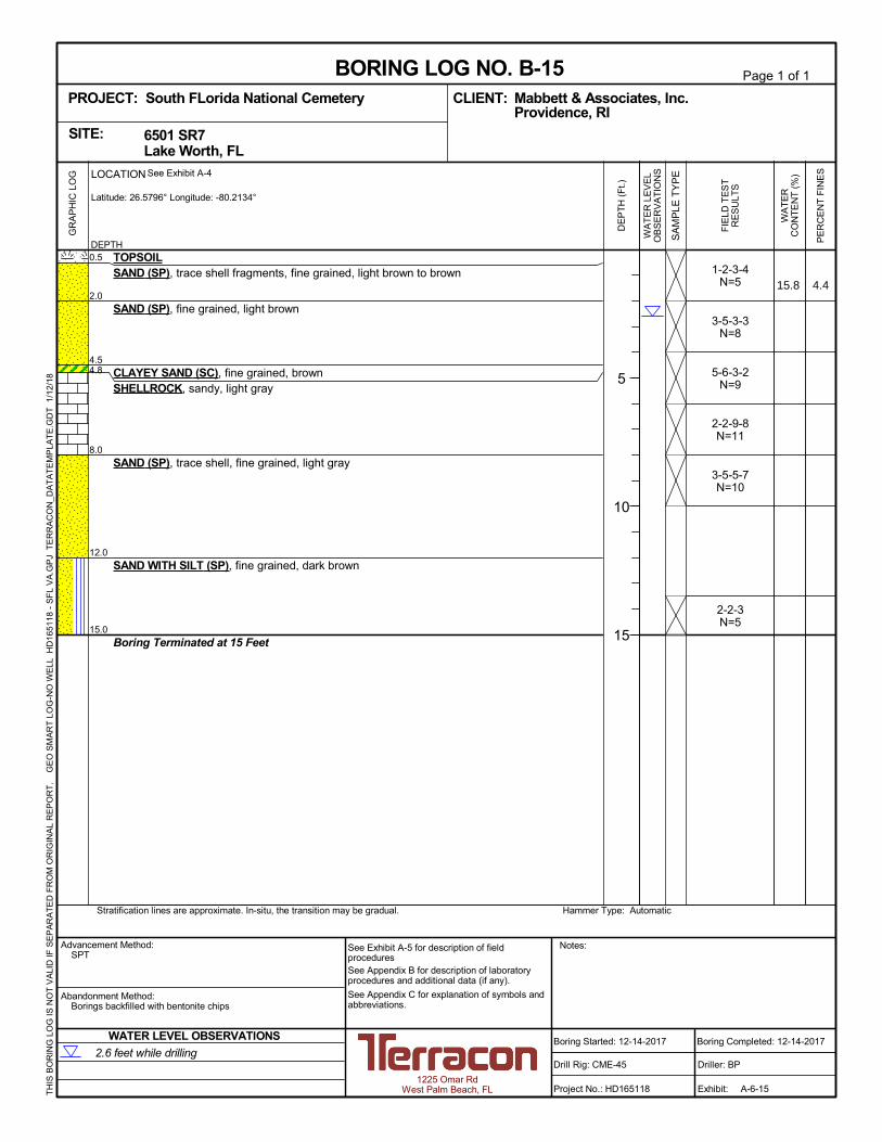
1-2-3-4 N=5
3-5-3-3 N=8
5-6-3-2 N=9
2-2-9-8 N=11
3-5-5-7 N=10
2-2-3 N=5
0.5
2.0
4.5 4.8
8.0
12.0
15.0
TOPSOIL SAND (SP), trace shell fragments, fine grained, light brown to brown
SAND (SP), fine grained, light brown
CLAYEY SAND (SC), fine grained, brown SHELLROCK, sandy, light gray
SAND (SP), trace shell, fine grained, light gray
SAND WITH SILT (SP), fine grained, dark brown
Boring Terminated at 15 Feet
GR
AP
HIC
LO
G
Hammer Type: Automatic Stratification lines are approximate. In-situ, the transition may be gradual.
TH
IS B
OR
ING
LO
G IS
NO
T V
ALI
D IF
SE
PA
RA
TE
D F
RO
M O
RIG
INA
L R
EP
OR
T.
G
EO
SM
AR
T L
OG
-NO
WE
LL H
D16
5118
- S
FL
VA
.GP
J T
ER
RA
CO
N_D
AT
AT
EM
PLA
TE
.GD
T 1
/12/
18
PE
RC
EN
T F
INE
S
WA
TE
RC
ON
TE
NT
(%
)
WA
TE
R L
EV
EL
OB
SE
RV
AT
ION
S
DE
PT
H (
Ft.)
5
10
15
SA
MP
LE T
YP
E
FIE
LD T
ES
TR
ES
ULT
S
6501 SR7 Lake Worth, FL
SITE:
Page 1 of 1
Advancement Method: SPT
Abandonment Method: Borings backfilled with bentonite chips
Notes:
Project No.: HD165118
Drill Rig: CME-45
Boring Started: 12-14-2017
BORING LOG NO. B-15 Mabbett & Associates, Inc. CLIENT: Providence, RI
Driller: BP
Boring Completed: 12-14-2017
Exhibit: A-6-15
See Exhibit A-5 for description of field procedures See Appendix B for description of laboratory procedures and additional data (if any).
See Appendix C for explanation of symbols and abbreviations.
PROJECT: South FLorida National Cemetery
1225 Omar Rd West Palm Beach, FL
2.6 feet while drilling
WATER LEVEL OBSERVATIONS
DEPTH
LOCATION See Exhibit A-4
Latitude: 26.5796° Longitude: -80.2134°
15.8 4.4
~'\ ~-- -~
X ·. -I_-.
-·. 5Z_
X I_-.
-.·
1·.-. -. :
X ,, ,,· ~-
I -
-
- X --:
X :· -.·
·. -
I_-. -
: ·. ·.· -.•.:
-.•. :
[X .·:-i -·· . .-.,
5Z_ lrerracan

APPENDIX B – LABORATORY TESTING

lrerracon Geotechnical Engineering ReportSouth Florida National Cemetery Expansion ■ Lake Worth, Florida January 19, 2018 ■ Terracon Project No. HD165118
Laboratory Testing
During the field exploration, a portion of each recovered sample was sealed in a jar and transported to our laboratory for further visual observation and laboratory testing. The soil samples were classified in general accordance with the appended General Notes and the Unified Soil Classification System based on the material's texture and plasticity. The estimated group symbol for the Unified Soil Classification System is shown on the boring logs and a brief description of the Unified Soil Classification System is included in Appendix C.
Laboratory tests conducted include moisture content, wash 200 sieve, full gradation, corrosion series and redox potential. The tests were conducted in general accordance the appropriate ASTM procedures. The results of the tests have been included on the boring logs and are shown in tabular form as Exhibits B-2 and B-3. Grain size curves are included as Exhibits B-4-1 to B-4-5.
Responsive ■ Resourceful ■ Reliable Exhibit B-1

lrerracon EXHIBIT B-2
SUMMARY OF LABORATORY CLASSIFACTION TESTING SOUTH FLORIDA NATIONAL CEMETERY
LAKE WORTH, PALM BEACH COUNTY, FLORIDA TERRACON PROJECT NO. HD165118
Boring Number Depth (ft)
Moisture Content
(%)
Sieve Analysis (% passing) USCS Symbol
3/4" 3/8” #4 #10 #40 #100 #200
B-1 6.0 – 8.0 15.3 100 86.6 72.9 58.1 43.3 18.8 11.8 Shellrock B-3 2.0 – 4.0 21.0 - - - - - - 9.7 SP-SM B-4 0 – 2.0 19.3 - - - - - - 15.8 SM B-6 4.0 – 6.0 21.5 100 91.6 80.5 67.2 51.4 20.2 13.1 SC B-9 4.0 – 6.0 16.3 100 79.3 61.0 49.1 36.5 21.6 15.7 Shellrock
B-11 6.0 – 8.0 27.8 100 97.4 93.5 86.1 72.5 21.9 11.0 SP-SM B-14 4.0 – 4.7 14.9 - - - - - - 16.1 SC B-15 0.5 – 2.0 15.8 100 100 98.6 97.7 89.8 26.5 4.4 SP

lrerracon
I
I
EXHIBIT B-3
CORROSION SERIES TESTING RESULTS SOUTH FLORIDA NATIONAL CEMETERY
LAKE WORTH, PALM BEACH COUNTY, FLORIDA TERRACON PROJECT NO. HD165118
Location Depth (ft) pH Chloride Content (ppm)
Sulfate Content (ppm)
Resistivity (ohm-cm)
Red-Ox (mV)
Substructure Environmental Classification1
Steel Concrete
B-4 2.0 – 8.0 8.8 53 72 6,596 +644 Slightly Slightly Aggressive Aggressive
B-8 2.0 – 8.0 8.3 73 91 3,880 +649 Moderately Slightly Aggressive Aggressive
1 According to the criteria described in the Florida Department of Transportation (FDOT) Structures Manual Volume 1, Section 1.3 (Jan. 2012)

.s § 0
.s .s ~ ;? I? 0 12 I? .s [:! .s ~
st §1: :# I I I ~- :# I "' ,-! "' "'
\ ' \
~
~~ \ I\
r\. ~"'~ """" .... i\
~
' \ \
\
" "'~ ~
I I I I I I I I I I I
Perc
ent F
iner
by
Wei
ght
US STANDARD SIEVE OPENING IN INCHES | US STANDARD SIEVE NUMBERS | HYDROMETER
100
90
80
70
60
50
40
30
20
10
0 100 10 1 0.1 0.01
Grain Size in Millimeters
GRAIN SIZE DISTRIBUTION CURVE
Boring Number Sample Depth SOIL DESCRIPTION Moitsure Content (%)
B-1 6.0 - 8.0 Light gray sandy SHELLROCK 15.3
U.S. Sieve Number: % Passing:
3 in. 1-1/2 in. 1 in. 3/4 in. 3/8 in. No. 4 No. 10 No. 20 No. 40 No. 60 No. 100 No. 200 100 100 100 100 86.6 72.9 58.1 49.9 43.3 30.4 18.8 11.8
Eff. Size (D10) = N/A Unif. Coef. (D60/ D10) = N/A Mabbett & Associates, Inc. South Florida National Cemetery
Lake Worth, Palm Beach County, Florida Project Number : HD165118
Date : 1/12/18
SHEET B-4-1

.s § 0
.s .s ~ ;? I? 0 12 I? .s [:! .s ~
st §1: :# I I I ~- :# I "' ,-! "' "'
"~ ~1' i\.
"' i\ i\.
' "' l'I~ ... ...._
~
\ \
1
\ ' "'"' ~
I I I I I I I I I I I
Perc
ent F
iner
by
Wei
ght
US STANDARD SIEVE OPENING IN INCHES | US STANDARD SIEVE NUMBERS | HYDROMETER
100
90
80
70
60
50
40
30
20
10
0 100 10 1 0.1 0.01
Grain Size in Millimeters
GRAIN SIZE DISTRIBUTION CURVE
Boring Number Sample Depth SOIL DESCRIPTION Moitsure Content (%)
B-6 4.0 - 6.0 Light brown clayey SAND, some shell fragments 21.5
U.S. Sieve Number: % Passing:
3 in. 1-1/2 in. 1 in. 3/4 in. 3/8 in. No. 4 No. 10 No. 20 No. 40 No. 60 No. 100 No. 200 100 100 100 100 91.6 80.5 67.2 59.2 51.4 34.8 20.2 13.1
Eff. Size (D10) = N/A Unif. Coef. (D60/ D10) = N/A Mabbett & Associates, Inc. South Florida National Cemetery
Lake Worth, Palm Beach County, Florida Project Number : HD165118
Date : 1/12/18
SHEET B-4-2

.s § 0
.s .s ~ ;? I? 0 12 I? .s [:! .s ~
st §1: :# I I I ~- :# I "' ,-! "' "'
\ \
' ' '\. "i\
"'-~
!'I~~
"""i' j\'"
' ~ ....... 1'11'1 ...
I I I I I I I I I I I
Perc
ent F
iner
by
Wei
ght
US STANDARD SIEVE OPENING IN INCHES | US STANDARD SIEVE NUMBERS | HYDROMETER
100
90
80
70
60
50
40
30
20
10
0 100 10 1 0.1 0.01
Grain Size in Millimeters
GRAIN SIZE DISTRIBUTION CURVE
Boring Number Sample Depth SOIL DESCRIPTION Moitsure Content (%)
B-9 4.0 - 6.0 Light gray sandy SHELLROCK 16.3
U.S. Sieve Number: % Passing:
3 in. 1-1/2 in. 1 in. 3/4 in. 3/8 in. No. 4 No. 10 No. 20 No. 40 No. 60 No. 100 No. 200 100 100 100 100 79.3 61.0 49.1 42.1 36.5 29.2 21.6 15.7
Eff. Size (D10) = N/A Unif. Coef. (D60/ D10) = N/A Mabbett & Associates, Inc. South Florida National Cemetery
Lake Worth, Palm Beach County, Florida Project Number : HD165118
Date : 1/12/18
SHEET B-4-3

.s § 0
.s .s ~ ;? I? 0 12 I? .s [:! .s ~
st §1: :# I I I ~- :# I "' ,-! "' "' ----..... ....
"""" r-,.. ...... l"o,,._
~ I'-....... ~-
... "' " \
\
\ ~
\
\ '\
~~ ~
I I I I I I I I I I I
Perc
ent F
iner
by
Wei
ght
US STANDARD SIEVE OPENING IN INCHES | US STANDARD SIEVE NUMBERS | HYDROMETER
100
90
80
70
60
50
40
30
20
10
0 100 10 1 0.1 0.01
Grain Size in Millimeters
GRAIN SIZE DISTRIBUTION CURVE
Boring Number Sample Depth SOIL DESCRIPTION Moitsure Content (%)
B-11 6.0 - 8.0 Brown SAND with silt, some shell fragments 27.8
U.S. Sieve Number: % Passing:
3 in. 1-1/2 in. 1 in. 3/4 in. 3/8 in. No. 4 No. 10 No. 20 No. 40 No. 60 No. 100 No. 200 100 100 100 100 97.4 93.5 86.1 80.9 72.5 47.8 21.9 11.0
Eff. Size (D10) = N/A Unif. Coef. (D60/ D10) = N/A Mabbett & Associates, Inc. South Florida National Cemetery
Lake Worth, Palm Beach County, Florida Project Number : HD165118
Date : 1/12/18
SHEET B-4-4

.s § 0
.s .s ~ ;? I? 0 12 I? .s [:! .s ~
st §1: :# I I I ~- :# I "' ,-! "' "'
"" .. "~
\ ' \ \ ,
\
\ \ \
~
I I I I I I I I I I I
Perc
ent F
iner
by
Wei
ght
US STANDARD SIEVE OPENING IN INCHES | US STANDARD SIEVE NUMBERS | HYDROMETER
100
90
80
70
60
50
40
30
20
10
0 100 10 1 0.1 0.01
Grain Size in Millimeters
GRAIN SIZE DISTRIBUTION CURVE
Boring Number Sample Depth SOIL DESCRIPTION Moitsure Content (%)
B-15 0.5 - 2.0 Light brown fine SAND, trace shell 15.8
U.S. Sieve Number: % Passing:
3 in. 1-1/2 in. 1 in. 3/4 in. 3/8 in. No. 4 No. 10 No. 20 No. 40 No. 60 No. 100 No. 200 100 100 100 100 100 98.6 97.7 96.6 89.8 61.4 26.5 4.4
Eff. Size (D10) = 0.09 mm Unif. Coef. (D60/ D10) = 2.78 Mabbett & Associates, Inc. South Florida National Cemetery
Lake Worth, Palm Beach County, Florida Project Number : HD165118
Date : 1/12/18
SHEET B-4-5

APPENDIX C SUPPORTING DOCUMENTS

.5L
rn a x_
_y_
~ 0 I ~
lrerracan
GENERAL NOTES DESCRIPTION OF SYMBOLS AND ABBREVIATIONS
Water Initially (HP) Hand Penetrometer Encountered
Water Level After a (T) Torvane Specified Period of Time Auger Rock Core Cuttings
Water Level After
WA
TE
R L
EV
EL
FIE
LD
TE
ST
S
(DCP) Dynamic Cone Penetrometer
(PID) Photo-Ionization Detector
(OVA) Organic Vapor Analyzer SA
MP
LIN
G
a Specified Period of Time
Water levels indicated on the soil boring logs are the levels measured in the borehole at the times indicated. Groundwater level variations will occur
Grab No Sample Recovery
Standard Penetration Shelby
Tube over time. In low permeability soils, Test accurate determination of groundwater levels is not possible with short term water level observations.
DESCRIPTIVE SOIL CLASSIFICATION
Soil classification is based on the Unified Soil Classification System. Coarse Grained Soils have more than 50% of their dry weight retained on a #200 sieve; their principal descriptors are: boulders, cobbles, gravel or sand. Fine Grained Soils have less than 50% of their dry weight retained on a #200 sieve; they are principally described as clays if they are plastic, and silts if they are slightly plastic or non-plastic. Major constituents may be added as modifiers and minor constituents may be added according to the relative proportions based on grain size. In addition to gradation, coarse-grained soils are defined on the basis of their in-place relative density and fine-grained soils on the basis of their consistency.
LOCATION AND ELEVATION NOTES
Unless otherwise noted, Latitude and Longitude are approximately determined using a hand-held GPS device. The accuracy of such devices is variable. Surface elevation data annotated with +/- indicates that no actual topographical survey was conducted to confirm the surface elevation. Instead, the surface elevation was approximately determined from topographic maps of the area.
ST
RE
NG
TH
TE
RM
S
RELATIVE DENSITY OF COARSE-GRAINED SOILS
(More than 50% retained on No. 200 sieve.) Density determined by Standard Penetration Resistance
CONSISTENCY OF FINE-GRAINED SOILS
(50% or more passing the No. 200 sieve.) Consistency determined by laboratory shear strength testing, field
visual-manual procedures or standard penetration resistance
Descriptive Term (Density)
Automatic Hammer SPT N-Value (Blows/Ft.)
Descriptive Term (Consistency)
Unconfined Compressive Strength Qu, (psf)
Automatic Hammer SPT N-Value (Blows/Ft.)
Very Loose < 3 Very Soft less than 500 < 1
Loose 3 - 8 Soft 500 to 1,000 1 - 3
Medium Dense 8 - 24 Medium Stiff 1,000 to 2,000 3 - 6
Dense 24 - 40 Stiff 2,000 to 4,000 6 - 12
Very Dense > 40 Very Stiff 4,000 to 8,000 12 - 24
Hard > 8,000 > 24
RELATIVE PROPORTIONS OF SAND AND GRAVEL GRAIN SIZE TERMINOLOGY
Descriptive Term(s) of other constituents
Percent of Dry Weight
Major Component of Sample
Particle Size
Trace With Modifier
< 15 15 - 29 > 30
Boulders Cobbles Gravel Sand Silt or Clay
Over 12 in. (300 mm) 12 in. to 3 in. (300mm to 75mm) 3 in. to #4 sieve (75mm to 4.75 mm) #4 to #200 sieve (4.75mm to 0.075mm Passing #200 sieve (0.075mm)
RELATIVE PROPORTIONS OF FINES PLASTICITY DESCRIPTION
Descriptive Term(s) of other constituents
Trace With Modifier
Percent of Dry Weight
< 5 5 - 12 > 12
Term
Non-plastic Low Medium High
Plasticity Index
0 1 - 10 11 - 30
> 30
Exhibit: C-1

i:L -X w 0 z
~ u f'.= Cf) <( ....J a..
6° For c11assific~tion ot'tine-gra1ined / I // /v soils and fine-grained fraction / 1. /.,,.,, /
50 - ;:::i:~s:f·~;.~~~:= soils / ,,-,$ i~~.,,..✓--+---,,-+\>--, 0~e ,,, __ " --+-------i
Horizontal at Pl=4 to LL=25.5. // I .>. / 40 - then Pl=0.73 (LL-20) / / Q'°-+---0------,f-------,f-----+----1
Equation of "U" - line / / ~ o" / V Vertical at LL=16 to Pl=7 / // V /
30 - then Pl=0.9 (L/L-8) / ,' /
// o" / o"
20 / o"---/-+-----+----+---+----+-----f-----<
/ /✓// // 10 / , ✓ V : =-/ CL- ML / ML or OL o/ : I
MH or OH
0 10 16 20 30 40 50 60 70 80 90 100 110
LIQUID LIMIT (LL)
lrerracon
UNIFIED SOIL CLASSIFICATION SYSTEM
Criteria for Assigning Group Symbols and Group Names Using Laboratory Tests A Soil Classification
Group Symbol Group Name B
Coarse Grained Soils: More than 50% retained on No. 200 sieve
Gravels: More than 50% of coarse fraction retained on No. 4 sieve
Clean Gravels: Less than 5% fines C
Cu 4 and 1 Cc 3 E GW Well-graded gravel F
Cu 4 and/or 1 Cc 3 E GP Poorly graded gravel F
Gravels with Fines: More than 12% fines C
Fines classify as ML or MH GM Silty gravel F,G,H
Fines classify as CL or CH GC Clayey gravel F,G,H
Sands: 50% or more of coarse fraction passes No. 4 sieve
Clean Sands: Less than 5% fines D
Cu 6 and 1 Cc 3 E SW Well-graded sand I
Cu 6 and/or 1 Cc 3 E SP Poorly graded sand I
Sands with Fines: More than 12% fines D
Fines classify as ML or MH SM Silty sand G,H,I
Fines classify as CL or CH SC Clayey sand G,H,I
Fine-Grained Soils: 50% or more passes the No. 200 sieve
Silts and Clays: Liquid limit less than 50
Inorganic: PI 7 and plots on or above “A” line J CL Lean clay K,L,M
PI 4 or plots below “A” line J ML Silt K,L,M
Organic: Liquid limit - oven dried
0.75 OL Organic clay K,L,M,N
Liquid limit - not dried Organic silt K,L,M,O
Silts and Clays: Liquid limit 50 or more
Inorganic: PI plots on or above “A” line CH Fat clay K,L,M
PI plots below “A” line MH Elastic Silt K,L,M
Organic: Liquid limit - oven dried
0.75 OH Organic clay K,L,M,P
Liquid limit - not dried Organic silt K,L,M,Q
Highly organic soils: Primarily organic matter, dark in color, and organic odor PT Peat
A Based on the material passing the 3-inch (75-mm) sieve B If field sample contained cobbles or boulders, or both, add “with cobbles
or boulders, or both” to group name. C Gravels with 5 to 12% fines require dual symbols: GW-GM well-graded
gravel with silt, GW-GC well-graded gravel with clay, GP-GM poorly graded gravel with silt, GP-GC poorly graded gravel with clay.
D Sands with 5 to 12% fines require dual symbols: SW-SM well-graded sand with silt, SW-SC well-graded sand with clay, SP-SM poorly graded sand with silt, SP-SC poorly graded sand with clay
(D )2
E Cu = D60/D10 Cc = 30
D x D 10 60 F If soil contains 15% sand, add “with sand” to group name. G If fines classify as CL-ML, use dual symbol GC-GM, or SC-SM.
H If fines are organic, add “with organic fines” to group name. I If soil contains 15% gravel, add “with gravel” to group name. J If Atterberg limits plot in shaded area, soil is a CL-ML, silty clay. K If soil contains 15 to 29% plus No. 200, add “with sand” or “with gravel,”
whichever is predominant. L If soil contains 30% plus No. 200 predominantly sand, add “sandy” to
group name. M If soil contains 30% plus No. 200, predominantly gravel, add
“gravelly” to group name. N PI 4 and plots on or above “A” line. O PI 4 or plots below “A” line. P PI plots on or above “A” line. Q PI plots below “A” line.
Exhibit C-2


![CE 6501 ITS [Compatibility Mode]](https://img.dokumen.tips/doc/110x75/577cd3161a28ab9e7896a680/ce-6501-its-compatibility-mode.jpg)