Embed Size (px)
Citation preview
GEOSYNTHETICS ENGINEERING: IN THEORY AND PRACTICE
Prof. J. N. Mandal
Department of Civil Engineering, IIT Bombay, Powai , Mumbai 400076, India. Tel.022-25767328email: [email protected]
Prof. J. N. Mandal, Department of Civil Engineering, IIT Bombay
Module-10LECTURE- 50
GEOSYNTHETICS FOR IMPROVEMENT IN BEARING CAPACITY
Prof. J. N. Mandal, Department of Civil Engineering, IIT Bombay
INTRODUCTION
METALLIC STRIPS ON COMPRESSIBLE SANDS
GEOTEXTILE OR GEOGRID IN CLAY OR SAND-CLAY INTERFACE
BEARING CAPACITY OF REINFORCED SOIL
BEARING CAPACITY OF STRIP FOOTING WITH GEOSYNTHETIC
AT SAND CLAY INTERFACE
GEOCELL REINFORCED SAND OVERLAYING SOFT CLAY
GEOCELL UNDER REPETITIVE LOADING
CHARACTERISTICS OF THREE DIMENSIONAL GEOCELL
OUTLINE
Prof. J. N. Mandal, Department of Civil Engineering, IIT Bombay
GEOSYNTHETICS FOR IMPROVEMENT IN BEARINGCAPACITY
The high strength geosynthetics can be used as basalreinforcement for the construction of embankment over softcompressible foundation soils.
Geosynthetic layers are placed horizontally with closerspacing for the construction of mechanically stabilizedreinforced soil walls, steep slopes over foundation soil.
The geosynthetics can also be used below the footings ofrigid walls rested over poor foundation soils.
Prof. J. N. Mandal, Department of Civil Engineering, IIT Bombay
Metallic Strips over Compressible SandsBinquet and Lee (1975a and 1975b) reported theimprovement in bearing capacity of compressible sandusing metallic reinforcements. The failure mechanismswere reported as follows and also depicted in Figure 10.1.
Shear above the reinforcement: u/B > 2/3 Tie pullout: u/B < 2/3, N < 2 or 3, short ties Upper ties break: u/B < 2/3 long ties, N > 4 Excessive long term deformation
u = distance from bottom of the footing to first layer ofreinforcement,B = width of the footing, and N = number of layer of reinforcement
Prof. J. N. Mandal, Department of Civil Engineering, IIT Bombay
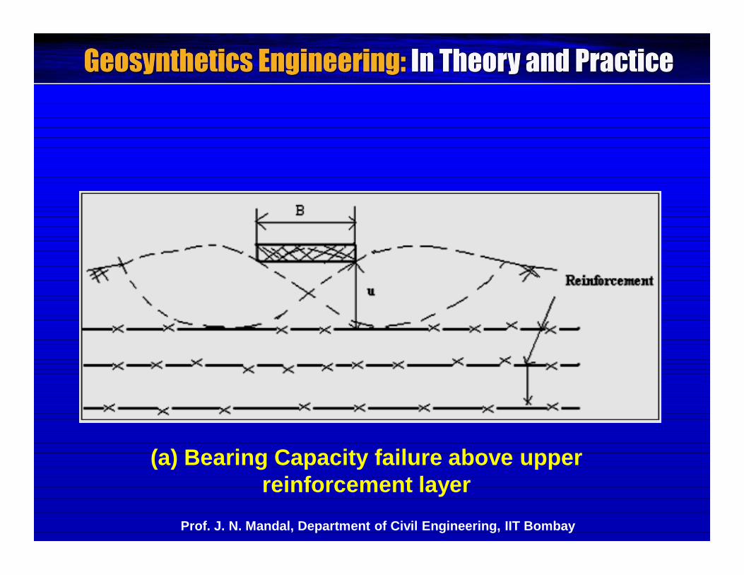
(a) Bearing Capacity failure above upper reinforcement layer
Prof. J. N. Mandal, Department of Civil Engineering, IIT Bombay
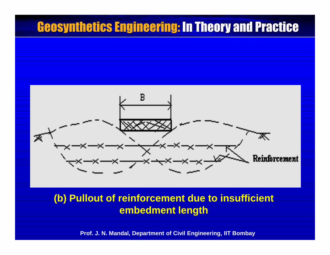
(b) Pullout of reinforcement due to insufficient embedment length
Prof. J. N. Mandal, Department of Civil Engineering, IIT Bombay
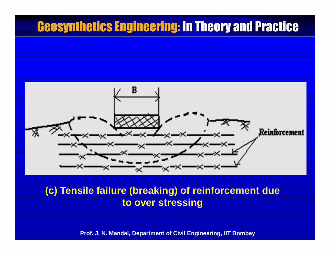
(c) Tensile failure (breaking) of reinforcement due to over stressing
Prof. J. N. Mandal, Department of Civil Engineering, IIT Bombay
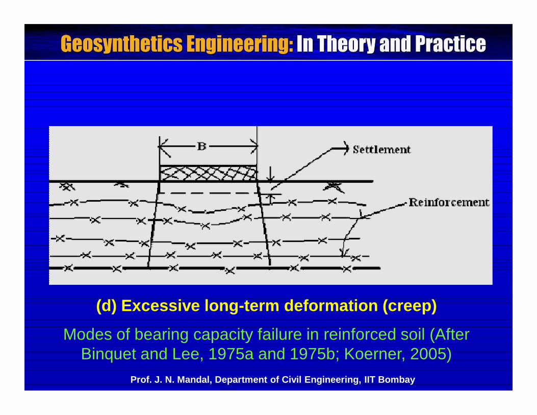
(d) Excessive long-term deformation (creep)
Prof. J. N. Mandal, Department of Civil Engineering, IIT Bombay
Modes of bearing capacity failure in reinforced soil (AfterBinquet and Lee, 1975a and 1975b; Koerner, 2005)
A definite improvement was observed in the bearingcapacity and consequently savings in cost and time.
Due to the problem of corrosion, the use of metallicreinforcements is ruled out.
Therefore, it is preferable and suitable to use non-corroding polymeric geosynthetics as reinforcing materials.
The geosynthetics can effectively be used to improve thebearing capacity of the soft foundation soils.
Prof. J. N. Mandal, Department of Civil Engineering, IIT Bombay
Geotextile or Geogrid in Clay or Sand-Clay Interface
The plate bearing tests on model footing rested over clay,reinforced with geotextile or geogrid placed horizontally inclay or sand-clay interface, shows beneficial increase in thebearing capacity of clay (Sah, 1990; Mandal and Sah,1991).
- Increase in the bearing capacity is more in case of geogridreinforcement.
Guido et al. (1985) used nonwoven heat bondedgeotextile over loose sand with 50% relative density.
Prof. J. N. Mandal, Department of Civil Engineering, IIT Bombay
Geosynthetic research institute used woven slit filmgeotextile over soft compressible fine-grained soil atsaturation above plastic limit with undrained shear strengthof 12 kPa.
In all the above cases, the reinforcing benefit is realizedwhen the geotextile-soil system deforms.
- Greater improvement in bearing capacity is noticed atlarger deformation.
Prof. J. N. Mandal, Department of Civil Engineering, IIT Bombay
Bearing Capacity of Reinforced Soil
Model tests were conducted to evaluate the efficiency ofthe horizontal, vertical and inclined form of reinforcementsin improving the bearing capacity of sand sub-grade.
- Nonwoven geotextile, jute and coir rope mat were usedas horizontal reinforcements.
- Geogrids and bamboo sticks were used as vertical aswell as inclined form of reinforcements.
Prof. J. N. Mandal, Department of Civil Engineering, IIT Bombay
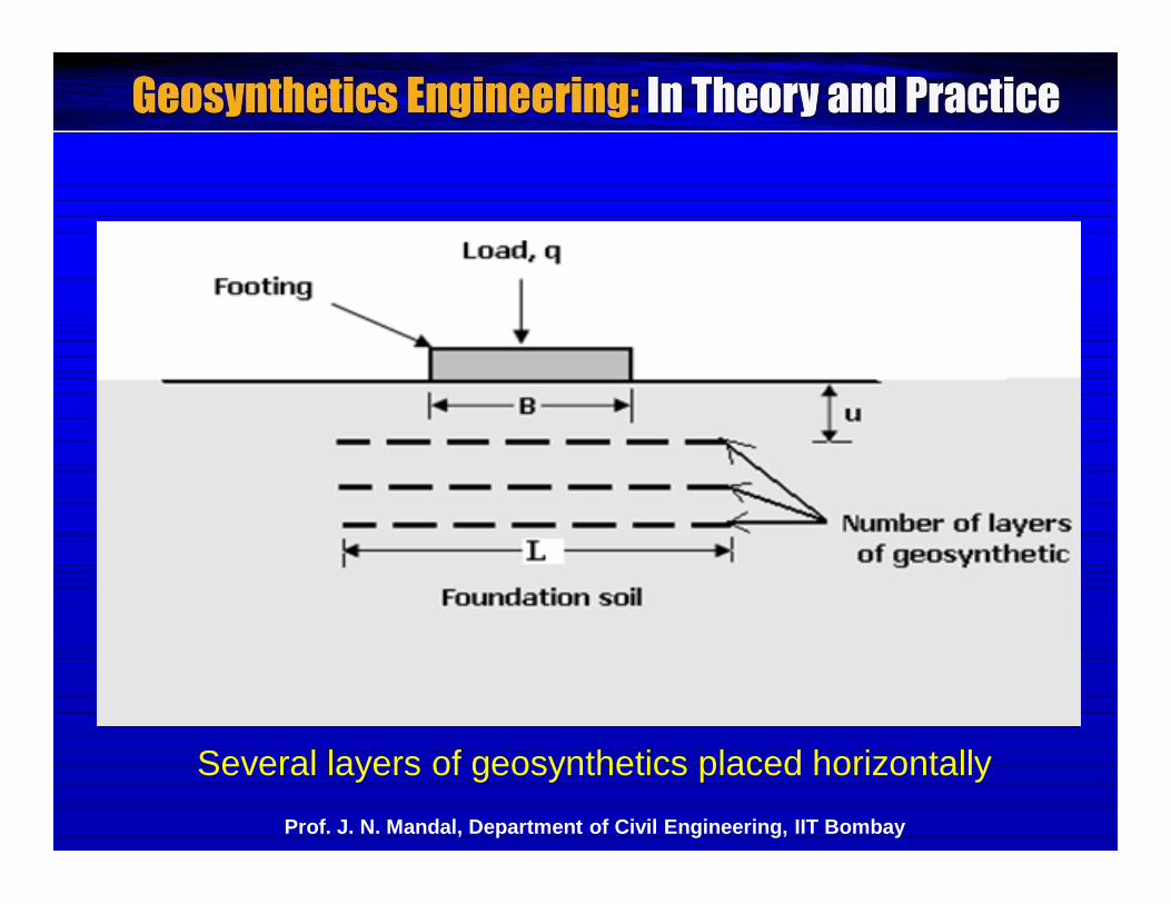
Several layers of geosynthetics placed horizontallyProf. J. N. Mandal, Department of Civil Engineering, IIT Bombay
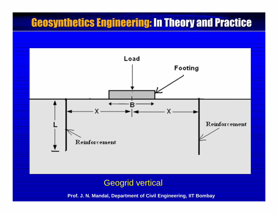
Geogrid verticalProf. J. N. Mandal, Department of Civil Engineering, IIT Bombay
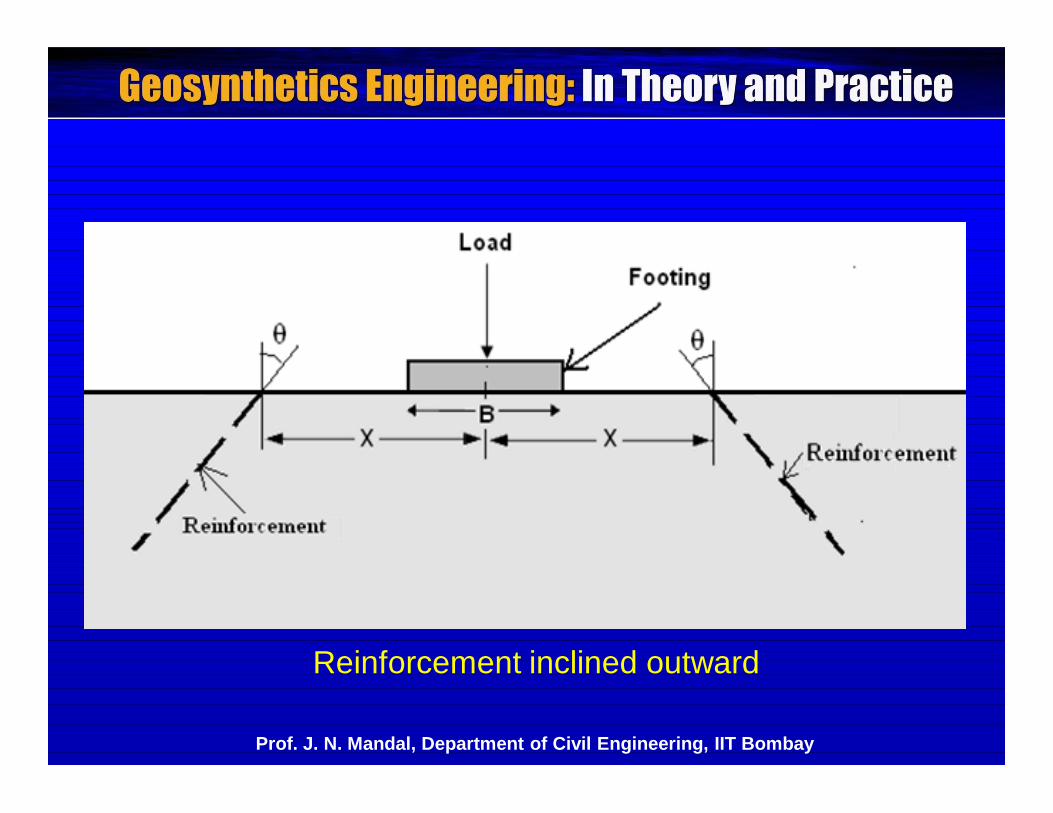
Reinforcement inclined outward
Prof. J. N. Mandal, Department of Civil Engineering, IIT Bombay
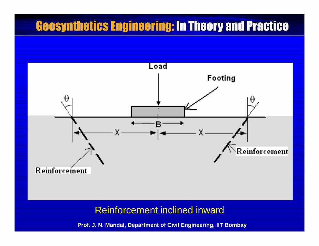
Reinforcement inclined inwardProf. J. N. Mandal, Department of Civil Engineering, IIT Bombay
The tests were conducted both on unreinforced andreinforced sand.
The ultimate bearing pressure for unreinforced sand (q0)was compared with ultimate bearing pressure of reinforcedsand (q). The bearing capacity ratio (BCR = q/q0) has beencomputed for all the tests.
Prof. J. N. Mandal, Department of Civil Engineering, IIT Bombay
Variation of BCR with u/B: Maximum bearing capacity was observed for u/B ratioof 0.25 for one layer of reinforcement.
-For u < 0.25 B, pullout resistance generated by thereinforcement is insufficient due to smaller overburdenand structural loads.
- For u > 0.25 B, lower resistance is resulted due to thefailure surface within the greater depth of the topunreinforced zone.
In none of the tests, the reinforcement broke indicatinga frictional failure in all the tests. At failure load, the footingsunk suddenly and the soil around the footing bulged.
Prof. J. N. Mandal, Department of Civil Engineering, IIT Bombay
Variation of BCR with L/B: The length was varied from 2.5B to 6B at increment of0.5 times of footing width ‘B’.
Bearing capacity ratio (BCR) increases rapidly withincrease in the length of reinforcement up to a length of6B and then remains relatively constant.
Variation of BCR with x/B: The tests were conducted for two types of reinforcingmaterials viz. geogrid and bamboo sticks in vertical fashion.
BCR was optimum at x = 0.5B for L/B = 2.0.
x = location of vertical reinforcement from centre of footingProf. J. N. Mandal, Department of Civil Engineering, IIT Bombay
Variation of BCR with inclination ():
The angle of inclination () of reinforcement with thevertical (inward or outward) was varied as 5, 10, 20 and 30degree.
The BCR decreases with increase in the angle ofinclination (i.e. inward or outward) of the reinforcement.
In both cases (Inward or outward), the maximum value ofBCR was obtained at = 5 degree.
Number of layers of reinforcements:
It has been observed that three layers of reinforcementare sufficient to improve the bearing capacity of the soil.
Prof. J. N. Mandal, Department of Civil Engineering, IIT Bombay
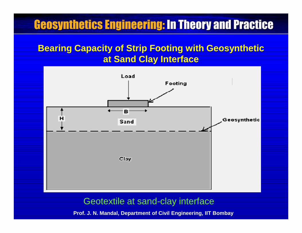
Bearing Capacity of Strip Footing with Geosynthetic at Sand Clay Interface
Geotextile at sand-clay interfaceProf. J. N. Mandal, Department of Civil Engineering, IIT Bombay
The bearing capacity of strip footing increases with theintroduction of geotextile reinforcement at the sand clayinterface (Mandal and Sah, 1991). In design, four modesof failure should be considered. Bearing Capacity failure above upper reinforcementlayer:The upper layer of geotextile should be laid within 300 mmbelow the ground surface to avoid bearing capacity failure.
Pullout of reinforcement due to insufficientembedment length:The pullout can be eliminated if we know how far theextension of geotextile should be placed beyond thepotential failure plane to mobilize the required resistinganchorage force.
Prof. J. N. Mandal, Department of Civil Engineering, IIT Bombay
Tensile failure or breaking of reinforcement due toover stressing:From laboratory load settlement curves, suitable datacan be selected for the design.
Excessive long-term deformation (creep)This kind of failure can occur from surface load andcorresponding geotextile stress-relaxation.
Prof. J. N. Mandal, Department of Civil Engineering, IIT Bombay
Bearing Capacity Using Geogrid:
- The bearing capacity of poor foundation granular soil canbe improved using geogrids.
- It can be used as continuous layers, multiple-closelyspaced continuous layers and honeycomb mattressesconsisting of three-dimensional interconnected geocells orgeoweb.- Milligan and Love (1984) conducted laboratory tests oncohesive soil using geogrids. It was reported that theimprovement in bearing capacity using geogrid was moreat higher deformation and nominal at lower deformation.
Prof. J. N. Mandal, Department of Civil Engineering, IIT Bombay
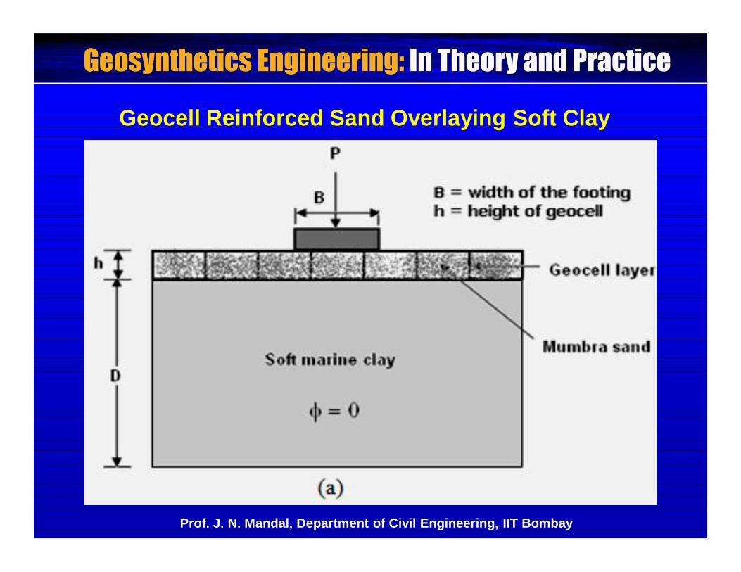
Geocell Reinforced Sand Overlaying Soft Clay
Prof. J. N. Mandal, Department of Civil Engineering, IIT Bombay
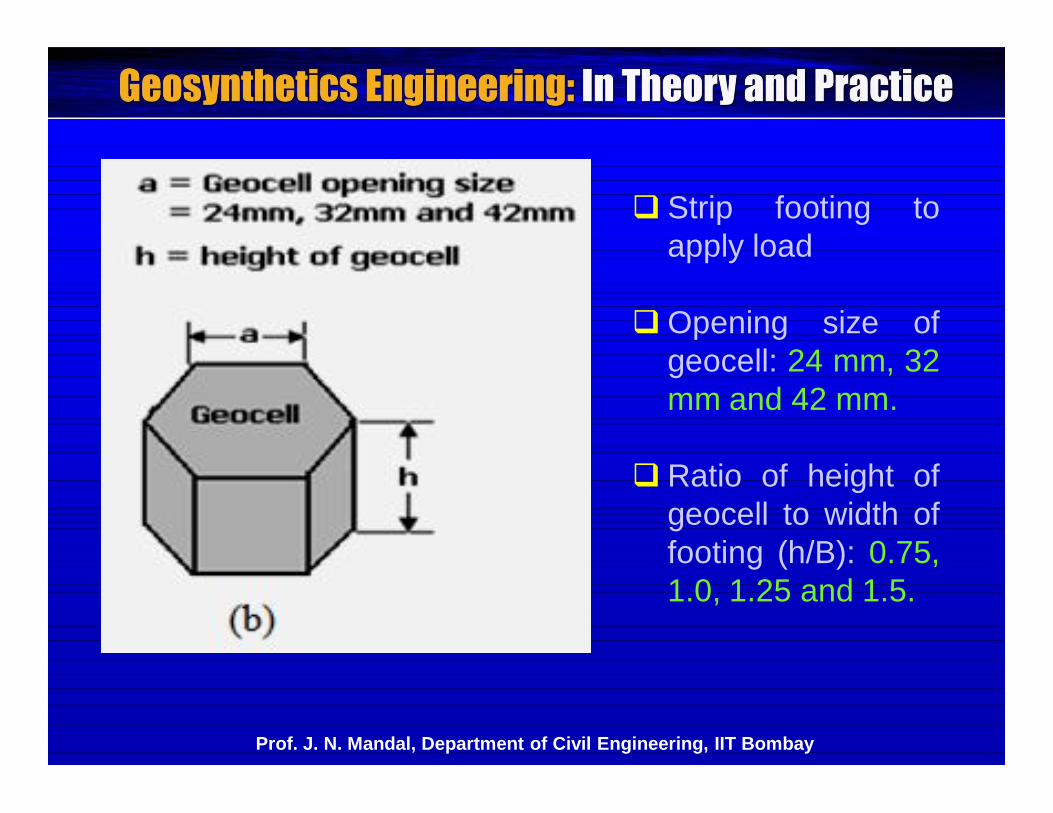
Strip footing toapply load
Opening size ofgeocell: 24 mm, 32mm and 42 mm.
Ratio of height ofgeocell to width offooting (h/B): 0.75,1.0, 1.25 and 1.5.
Prof. J. N. Mandal, Department of Civil Engineering, IIT Bombay
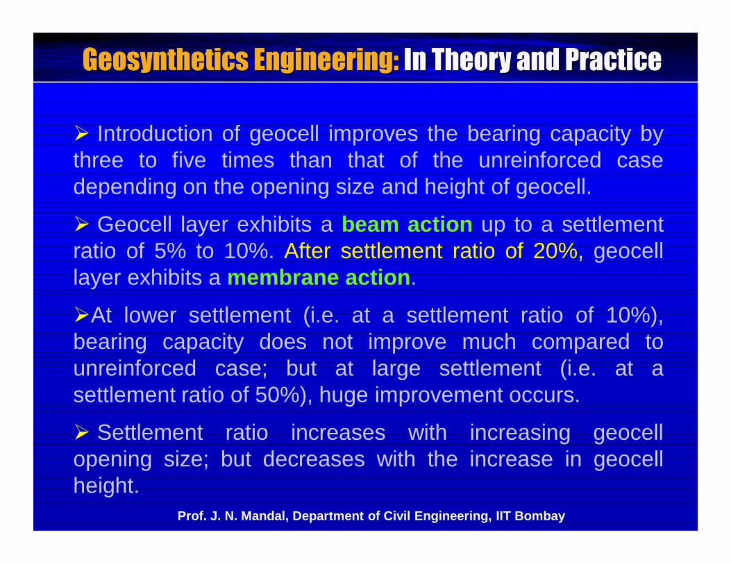
Introduction of geocell improves the bearing capacity bythree to five times than that of the unreinforced casedepending on the opening size and height of geocell.
Geocell layer exhibits a beam action up to a settlementratio of 5% to 10%. After settlement ratio of 20%, geocelllayer exhibits a membrane action.
At lower settlement (i.e. at a settlement ratio of 10%),bearing capacity does not improve much compared tounreinforced case; but at large settlement (i.e. at asettlement ratio of 50%), huge improvement occurs.
Settlement ratio increases with increasing geocellopening size; but decreases with the increase in geocellheight.
Prof. J. N. Mandal, Department of Civil Engineering, IIT Bombay
Geocell Under Repetitive Loading (Mhaiskar andMandal, 1992 and 1994)
- Experimental as well as finite element investigations ongeocell structures rested over a soft clay sub-grade.
- loose and dense sand as backfill material
- monotonic and repetitive, undrained, on-highway loadingconditions
Prof. J. N. Mandal, Department of Civil Engineering, IIT Bombay
Only a marginal benefit was gained by reinforcing thesand/clay interface with horizontal planar low modulusgeotextile whereas the geocells made of some low modulusgeotextile yielded substantial benefits.
Width of the geocell mattress can be optimized as threetimes the width of the plate.
Geocell mattress without and with planar geosyntheticreinforcements can be applied for embankment, earth dams,building foundations, live walls, retaining walls and slopes.
Repetitive loading tests indicated that the geocell structuresperform distinctly better compared to the unreinforced casesand with horizontal inclusion of geosynthetics.
Prof. J. N. Mandal, Department of Civil Engineering, IIT Bombay
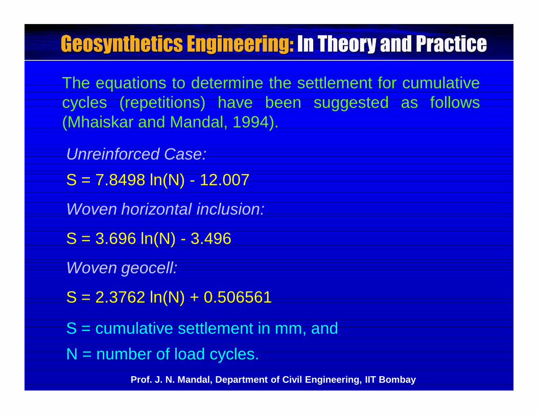
The equations to determine the settlement for cumulativecycles (repetitions) have been suggested as follows(Mhaiskar and Mandal, 1994).
Unreinforced Case:S = 7.8498 ln(N) - 12.007
Woven horizontal inclusion:
S = 3.696 ln(N) - 3.496
Woven geocell:
S = 2.3762 ln(N) + 0.506561
S = cumulative settlement in mm, andN = number of load cycles.
Prof. J. N. Mandal, Department of Civil Engineering, IIT Bombay
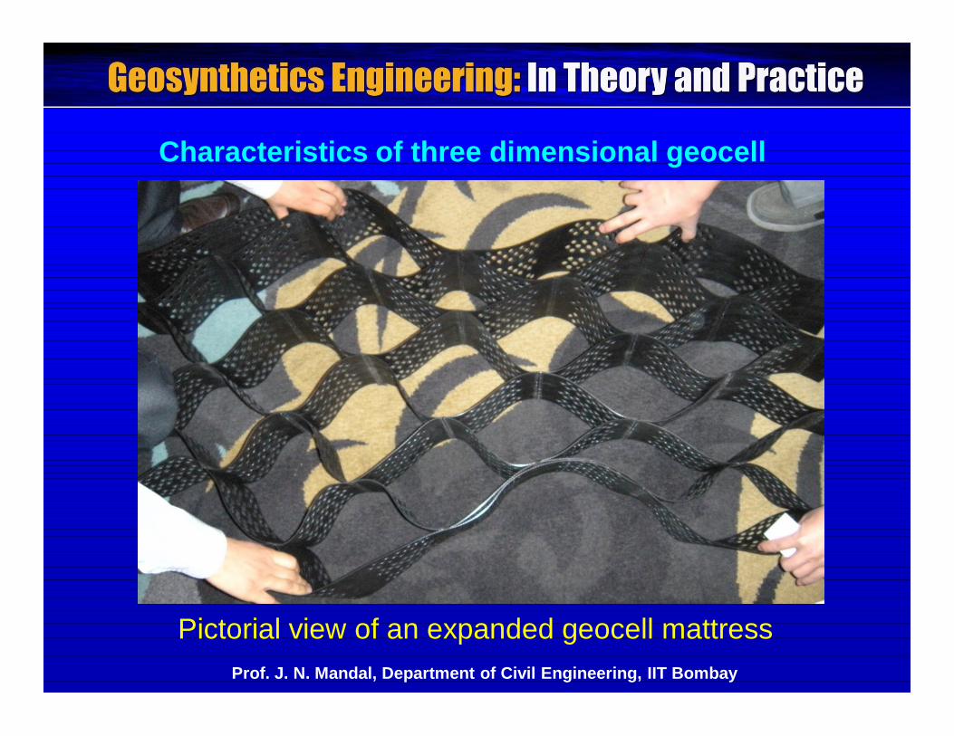
Characteristics of three dimensional geocell
Pictorial view of an expanded geocell mattressProf. J. N. Mandal, Department of Civil Engineering, IIT Bombay
- Due to the confinement effect of three dimensional geocell,there is an improvement in the shear strength of the granularsoil.
- The geocell can be projected in a collapsed configurationor an expanded form. It is a honeycombed threedimensional structure made of geogrid and placed verticallywith interconnected geocells in mattress form.
- The geocell is placed on the site, expanded and anchored.The granular soil is filled in geocell and compacted with theaid of a hand- operated vibratory plate compactor.
Prof. J. N. Mandal, Department of Civil Engineering, IIT Bombay
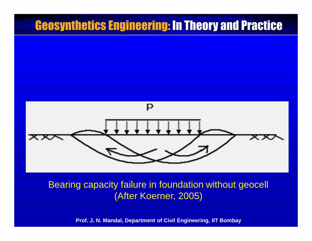
Bearing capacity failure in foundation without geocell (After Koerner, 2005)
Prof. J. N. Mandal, Department of Civil Engineering, IIT Bombay
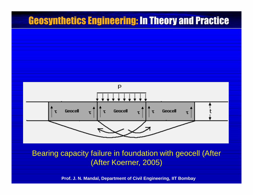
Bearing capacity failure in foundation with geocell (After (After Koerner, 2005)
Prof. J. N. Mandal, Department of Civil Engineering, IIT Bombay
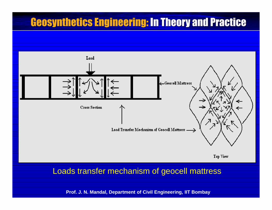
Loads transfer mechanism of geocell mattress
Prof. J. N. Mandal, Department of Civil Engineering, IIT Bombay
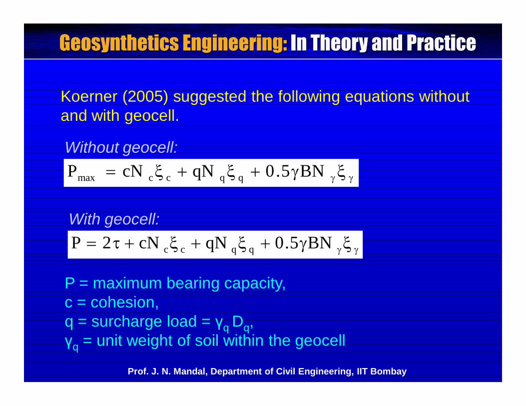
BN5.0qNcNP qqccmax
BN5.0qNcN2P qqcc
Koerner (2005) suggested the following equations withoutand with geocell.
With geocell:
Without geocell:
P = maximum bearing capacity,c = cohesion,q = surcharge load = γq Dq,γq = unit weight of soil within the geocell
Prof. J. N. Mandal, Department of Civil Engineering, IIT Bombay
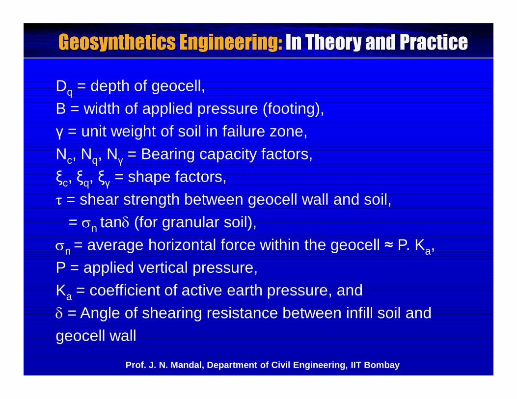
Dq = depth of geocell,B = width of applied pressure (footing),γ = unit weight of soil in failure zone,Nc, Nq, Nγ = Bearing capacity factors,ξc, ξq, ξγ = shape factors,τ = shear strength between geocell wall and soil,
= n tan (for granular soil),n = average horizontal force within the geocell ≈ P. Ka,P = applied vertical pressure,Ka = coefficient of active earth pressure, and = Angle of shearing resistance between infill soil andgeocell wall
Prof. J. N. Mandal, Department of Civil Engineering, IIT Bombay
The potential slip failure plane passes vertically throughgeocell and then to the underlying stiffer subsoil.
The failure mode is not circular arc. Possibly plasticfailure occurs and resulted in the improvement of bearingcapacity.
If the foundation soil is soft, a stable working platformcan be constructed with the help of both biaxial Geogridand a nonwoven geotextile.
Geocell mattress can be used for erosion control,retaining walls, slope stability, foundations and landfillproblems.
Prof. J. N. Mandal, Department of Civil Engineering, IIT Bombay
Geogrid cells are generally three dimensional geosyntheticstructures up to 1.0 m height.
Geogrid cells can be joined by plastic or steel rods orbodkin joint.
Edgar (1985) reported that a 32 m high embankment wasconstructed on soft soil economically and successfully.
The slip plane passes to the deeper and stiffer layer ofsubsoil through the geogrid cells and change the failuresurface in a greater way.
Prof. J. N. Mandal, Department of Civil Engineering, IIT Bombay
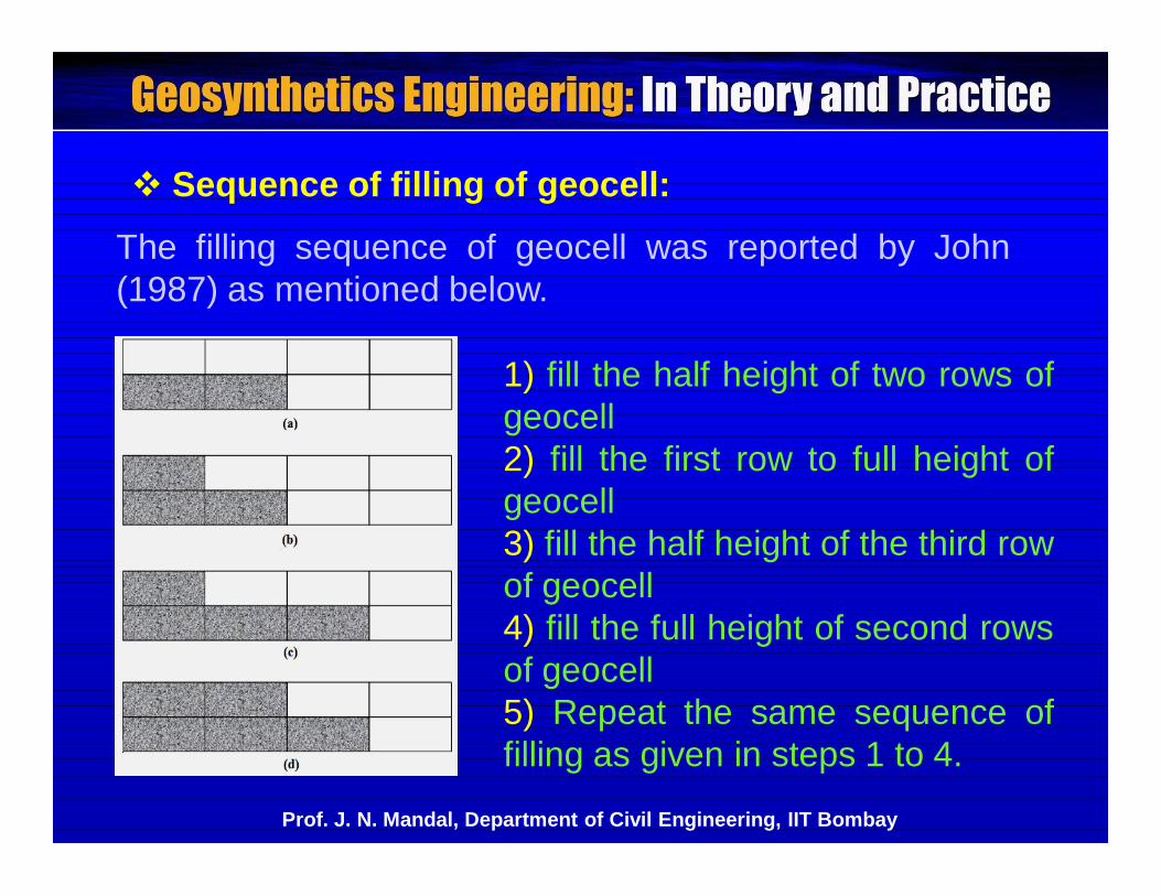
Sequence of filling of geocell:
The filling sequence of geocell was reported by John(1987) as mentioned below.
1) fill the half height of two rows ofgeocell2) fill the first row to full height ofgeocell3) fill the half height of the third rowof geocell4) fill the full height of second rowsof geocell5) Repeat the same sequence offilling as given in steps 1 to 4.
Prof. J. N. Mandal, Department of Civil Engineering, IIT Bombay
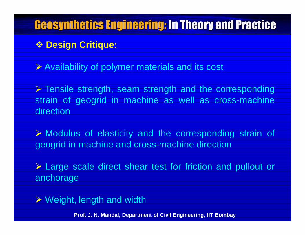
Design Critique:
Availability of polymer materials and its cost
Tensile strength, seam strength and the correspondingstrain of geogrid in machine as well as cross-machinedirection
Modulus of elasticity and the corresponding strain ofgeogrid in machine and cross-machine direction
Large scale direct shear test for friction and pullout oranchorage
Weight, length and widthProf. J. N. Mandal, Department of Civil Engineering, IIT Bombay
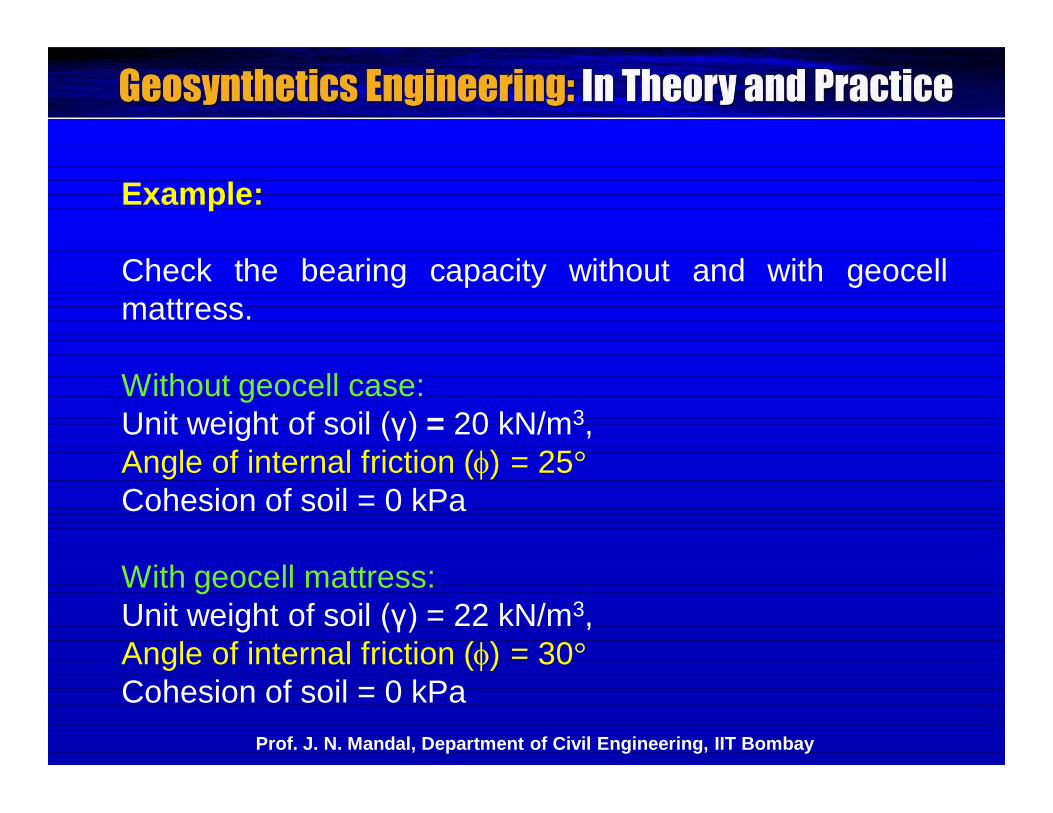
Example:
Check the bearing capacity without and with geocellmattress.
Without geocell case:Unit weight of soil (γ) = 20 kN/m3,Angle of internal friction () = 25°Cohesion of soil = 0 kPa
With geocell mattress:Unit weight of soil (γ) = 22 kN/m3,Angle of internal friction () = 30°Cohesion of soil = 0 kPa
Prof. J. N. Mandal, Department of Civil Engineering, IIT Bombay
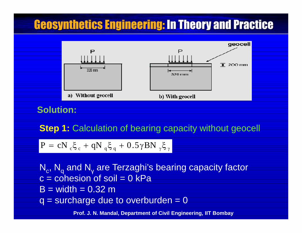
Step 1: Calculation of bearing capacity without geocell
BN5.0qNcNP qqcc
Nc, Nq and Nγ are Terzaghi’s bearing capacity factorc = cohesion of soil = 0 kPaB = width = 0.32 mq = surcharge due to overburden = 0
Solution:
Prof. J. N. Mandal, Department of Civil Engineering, IIT Bombay
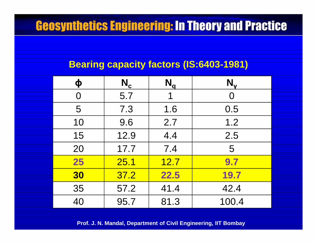
Bearing capacity factors (IS:6403-1981)
ɸ Nc Nq Nγ0 5.7 1 05 7.3 1.6 0.5
10 9.6 2.7 1.215 12.9 4.4 2.520 17.7 7.4 525 25.1 12.7 9.730 37.2 22.5 19.735 57.2 41.4 42.440 95.7 81.3 100.4
Prof. J. N. Mandal, Department of Civil Engineering, IIT Bombay
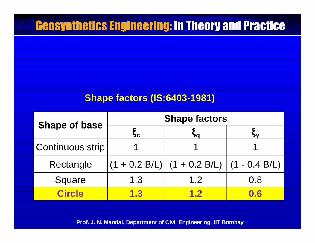
Shape factors (IS:6403-1981)
Shape of base Shape factorsξc ξq ξγ
Continuous strip 1 1 1
Rectangle (1 + 0.2 B/L) (1 + 0.2 B/L) (1 - 0.4 B/L)Square 1.3 1.2 0.8Circle 1.3 1.2 0.6
Prof. J. N. Mandal, Department of Civil Engineering, IIT Bombay
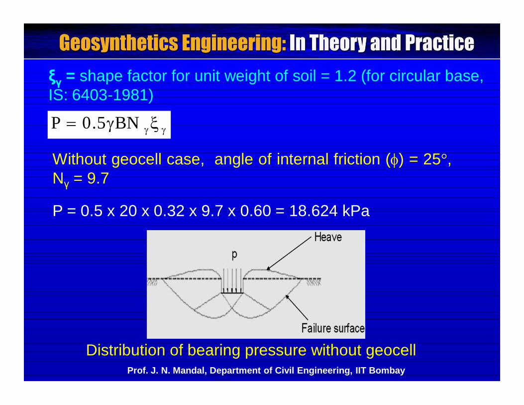
ξγ = shape factor for unit weight of soil = 1.2 (for circular base,IS: 6403-1981)
BN5.0P
Distribution of bearing pressure without geocellProf. J. N. Mandal, Department of Civil Engineering, IIT Bombay
P = 0.5 x 20 x 0.32 x 9.7 x 0.60 = 18.624 kPa
Without geocell case, angle of internal friction () = 25°,Nγ = 9.7
BN5.0qNcN2P qqcc
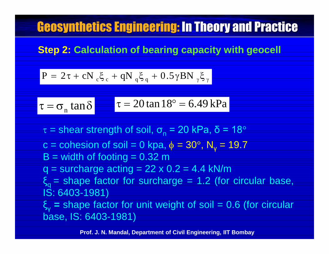
tann
Step 2: Calculation of bearing capacity with geocell
= shear strength of soil, σn = 20 kPa, δ = 18°
kPa49.618tan20
c = cohesion of soil = 0 kpa, = 30°, Nγ = 19.7B = width of footing = 0.32 mq = surcharge acting = 22 x 0.2 = 4.4 kN/mξq = shape factor for surcharge = 1.2 (for circular base,IS: 6403-1981)ξγ = shape factor for unit weight of soil = 0.6 (for circularbase, IS: 6403-1981)
Prof. J. N. Mandal, Department of Civil Engineering, IIT Bombay
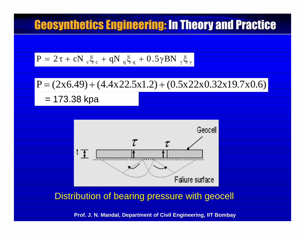
BN5.0qNcN2P qqcc
)6.0x7.19x32.0x22x5.0()2.1x5.22x4.4()49.6x2(P = 173.38 kpa
Distribution of bearing pressure with geocell
Prof. J. N. Mandal, Department of Civil Engineering, IIT Bombay
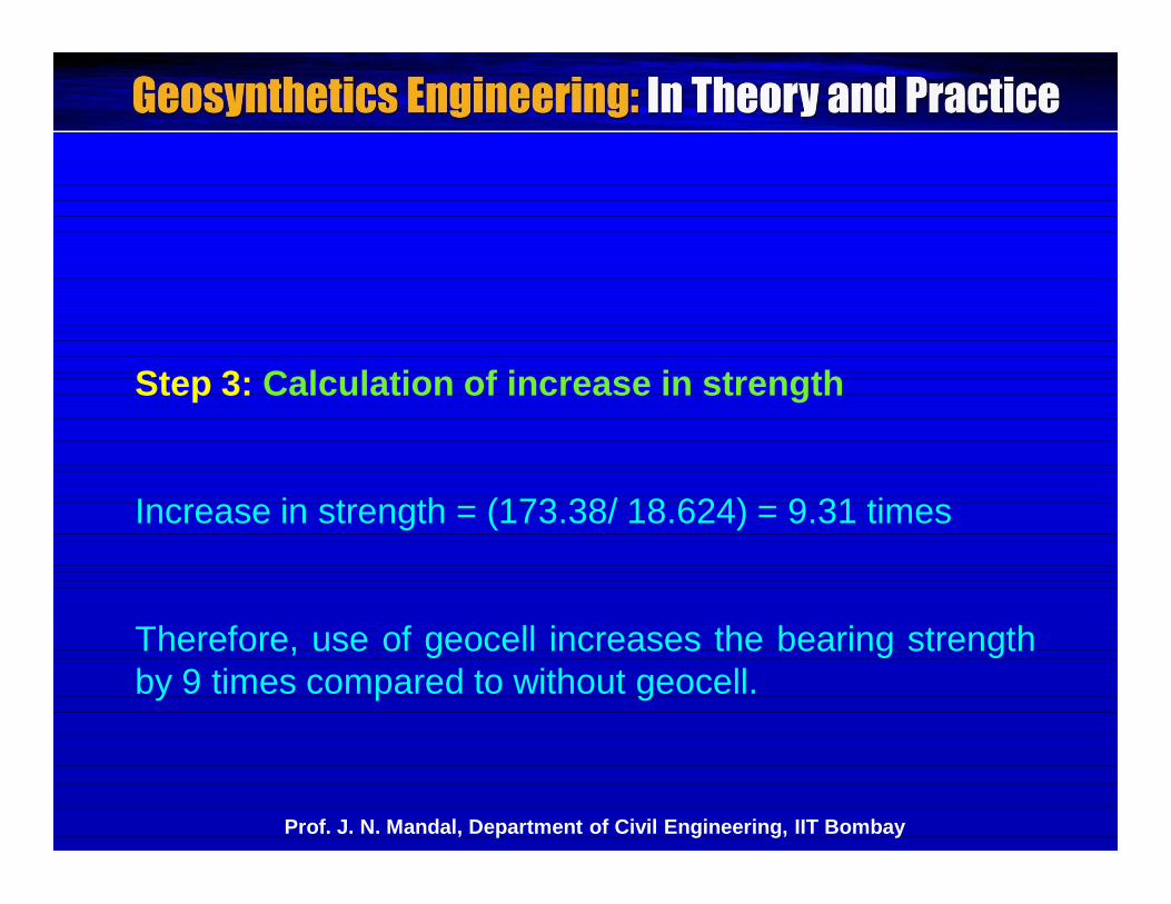
Step 3: Calculation of increase in strength
Increase in strength = (173.38/ 18.624) = 9.31 times
Therefore, use of geocell increases the bearing strengthby 9 times compared to without geocell.
Prof. J. N. Mandal, Department of Civil Engineering, IIT Bombay

Please let us hear from you
Any question?
Prof. J. N. Mandal, Department of Civil Engineering, IIT Bombay
Prof. J. N. Mandal
Department of civil engineering, IIT Bombay, Powai , Mumbai 400076, India. Tel.022-25767328email: [email protected]
Prof. J. N. Mandal, Department of Civil Engineering, IIT Bombay