Embed Size (px)
Citation preview

GEOSYNTHETICS ENGINEERING: IN THEORY AND PRACTICE
Prof. J. N. Mandal
Department of civil engineering, IIT Bombay, Powai , Mumbai 400076, India. Tel.022-25767328email: [email protected]
Prof. J. N. Mandal, Department of Civil Engineering, IIT Bombay
Module - 3LECTURE- 11
Geosynthetic properties and test methods
Prof. J. N. Mandal, Department of Civil Engineering, IIT Bombay
Prof. J. N. Mandal, Department of Civil Engineering, IIT Bombay
RECAP of previous lecture…..
When to test geosynthetics?
Physical Properties
Mechanical Properties (Partly Covered)
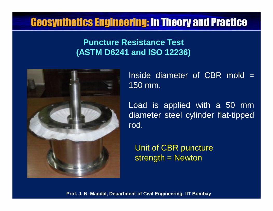
Puncture Resistance Test (ASTM D6241 and ISO 12236)
Unit of CBR puncture strength = Newton
Inside diameter of CBR mold =150 mm.
Load is applied with a 50 mmdiameter steel cylinder flat-tippedrod.
Prof. J. N. Mandal, Department of Civil Engineering, IIT Bombay
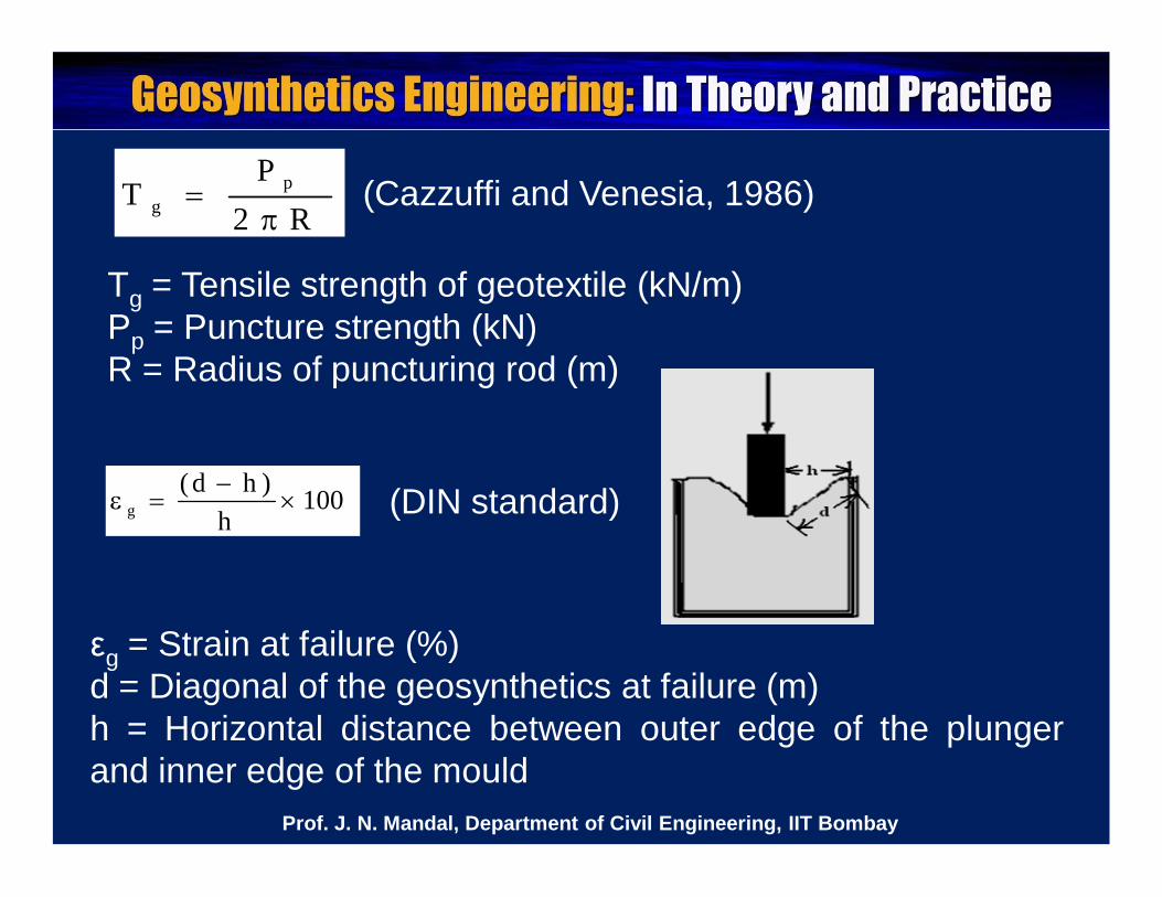
R2P
T pg
Tg = Tensile strength of geotextile (kN/m)Pp = Puncture strength (kN)R = Radius of puncturing rod (m)
(DIN standard)100h
)hd(g
εg = Strain at failure (%)d = Diagonal of the geosynthetics at failure (m)h = Horizontal distance between outer edge of the plungerand inner edge of the mould
(Cazzuffi and Venesia, 1986)
Prof. J. N. Mandal, Department of Civil Engineering, IIT Bombay
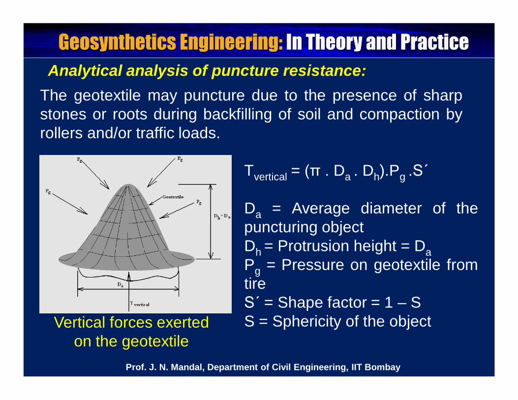
Analytical analysis of puncture resistance:The geotextile may puncture due to the presence of sharpstones or roots during backfilling of soil and compaction byrollers and/or traffic loads.
Vertical forces exerted on the geotextile
Tvertical = (π . Da . Dh).Pg .S΄
Da = Average diameter of thepuncturing objectDh = Protrusion height = DaPg = Pressure on geotextile fromtireS΄ = Shape factor = 1 – SS = Sphericity of the object
Prof. J. N. Mandal, Department of Civil Engineering, IIT Bombay
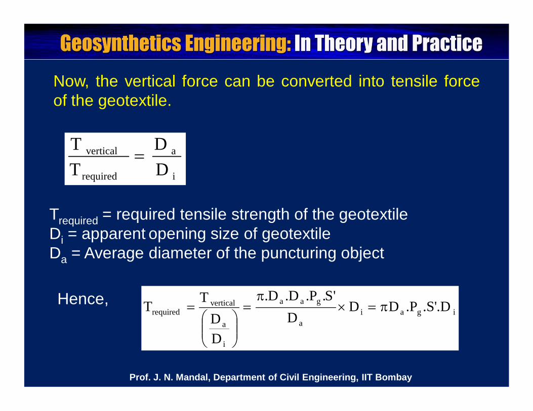
Now, the vertical force can be converted into tensile forceof the geotextile.
i
a
required
vertical
DD
TT
Trequired = required tensile strength of the geotextileDi = apparent opening size of geotextileDa = Average diameter of the puncturing object
Hence,igai
a
gaa
i
a
verticalrequired .S'.D.PDD
D'S.P.D.D.
DD
T T
Prof. J. N. Mandal, Department of Civil Engineering, IIT Bombay
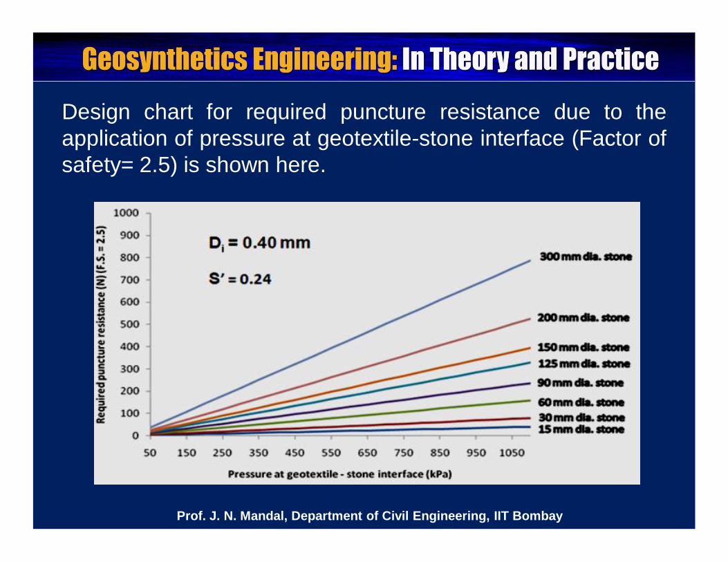
Design chart for required puncture resistance due to theapplication of pressure at geotextile-stone interface (Factor ofsafety= 2.5) is shown here.
Prof. J. N. Mandal, Department of Civil Engineering, IIT Bombay
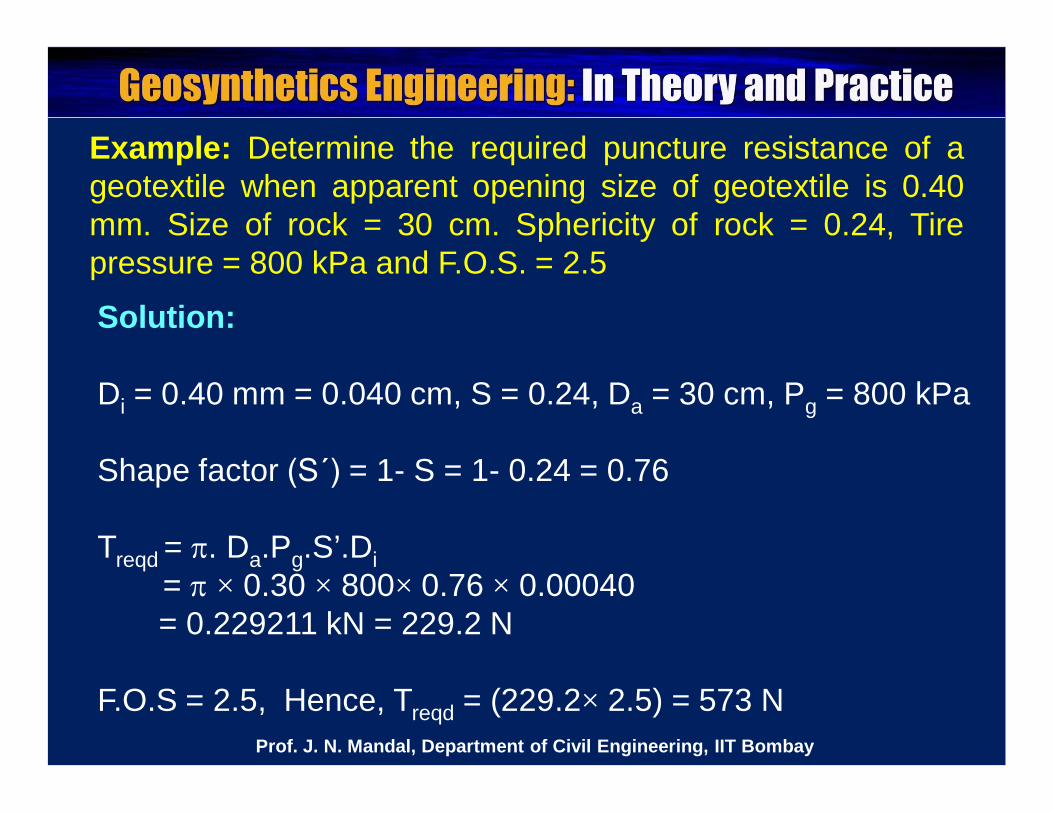
Example: Determine the required puncture resistance of ageotextile when apparent opening size of geotextile is 0.40mm. Size of rock = 30 cm. Sphericity of rock = 0.24, Tirepressure = 800 kPa and F.O.S. = 2.5
Solution:
Di = 0.40 mm = 0.040 cm, S = 0.24, Da = 30 cm, Pg = 800 kPa
Shape factor (S΄) = 1- S = 1- 0.24 = 0.76
Treqd = . Da.Pg.S’.Di= × 0.30 × 800× 0.76 × 0.00040= 0.229211 kN = 229.2 N
F.O.S = 2.5, Hence, Treqd = (229.2× 2.5) = 573 NProf. J. N. Mandal, Department of Civil Engineering, IIT Bombay
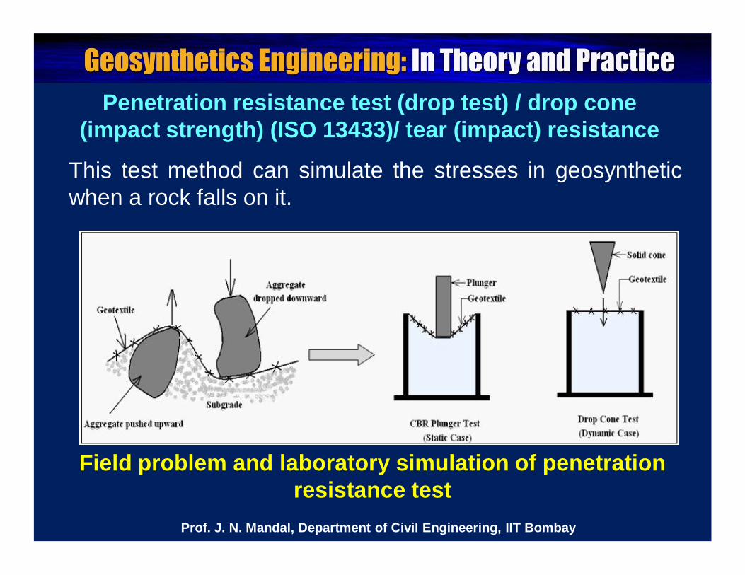
Penetration resistance test (drop test) / drop cone (impact strength) (ISO 13433)/ tear (impact) resistance
Field problem and laboratory simulation of penetration resistance test
This test method can simulate the stresses in geosyntheticwhen a rock falls on it.
Prof. J. N. Mandal, Department of Civil Engineering, IIT Bombay
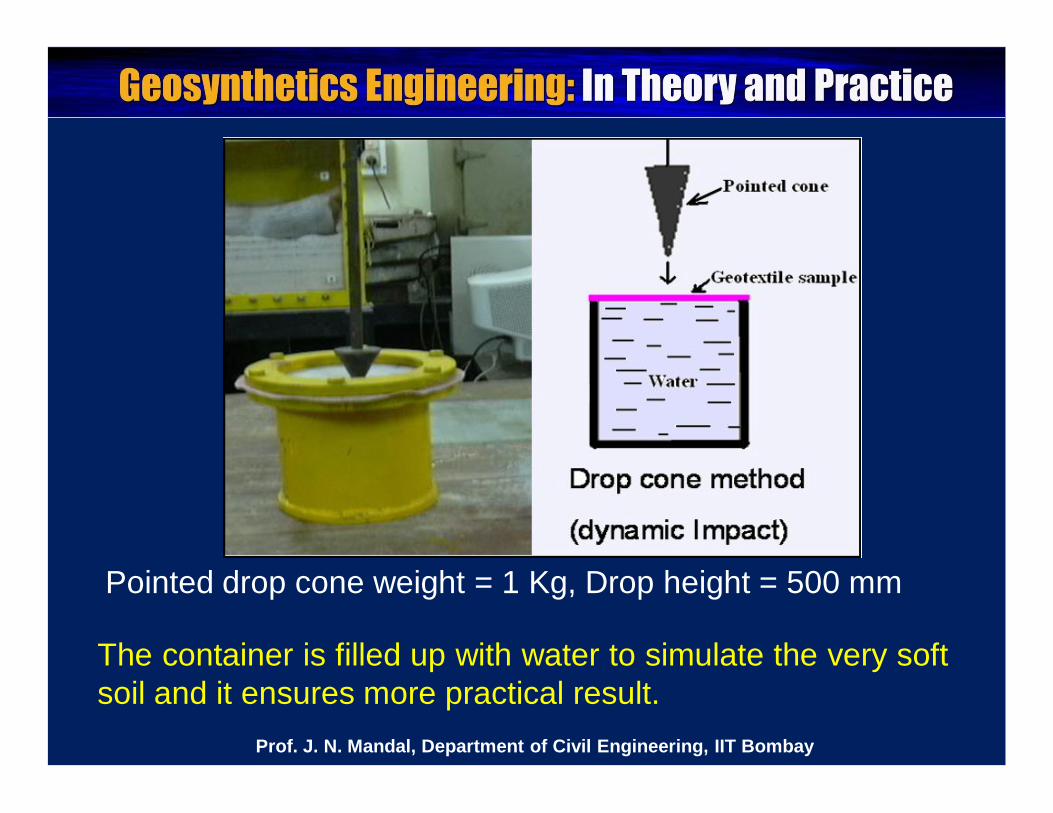
The container is filled up with water to simulate the very softsoil and it ensures more practical result.
Pointed drop cone weight = 1 Kg, Drop height = 500 mm
Prof. J. N. Mandal, Department of Civil Engineering, IIT Bombay
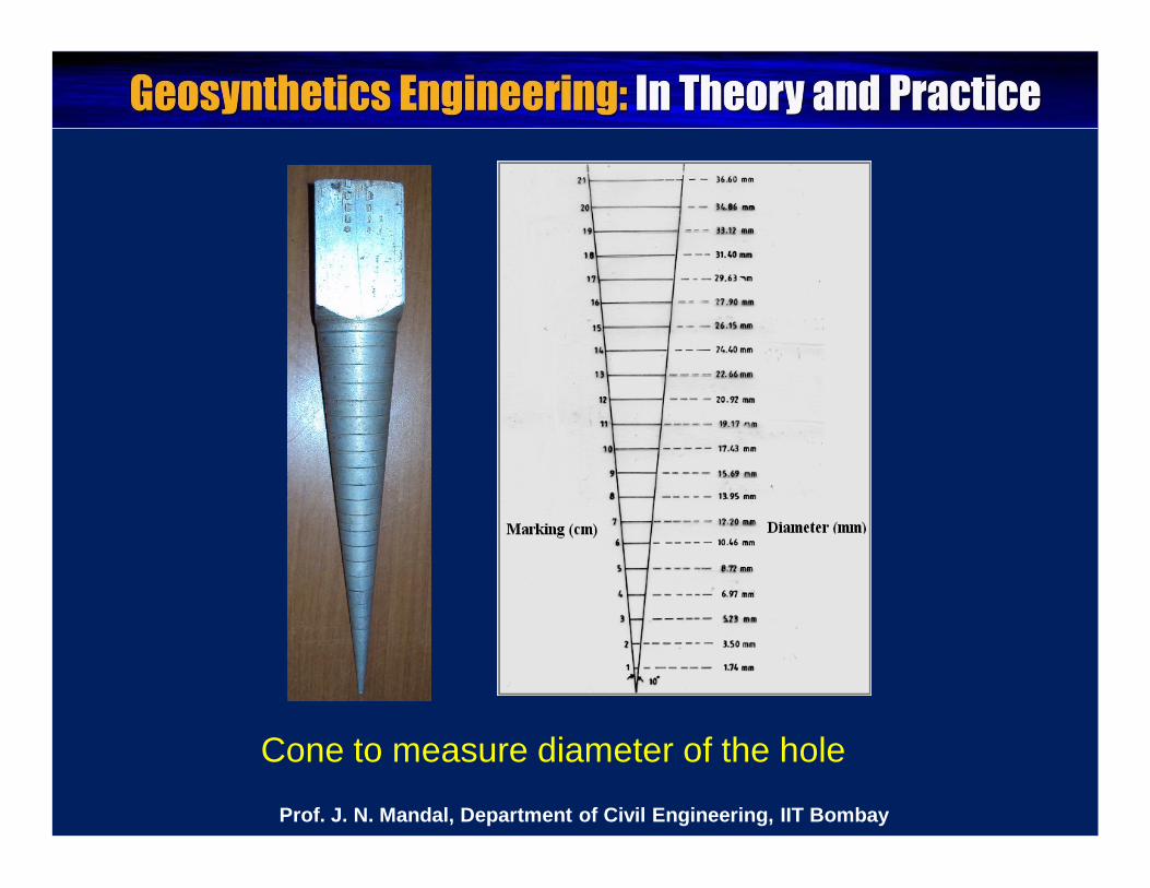
Cone to measure diameter of the hole
Prof. J. N. Mandal, Department of Civil Engineering, IIT Bombay
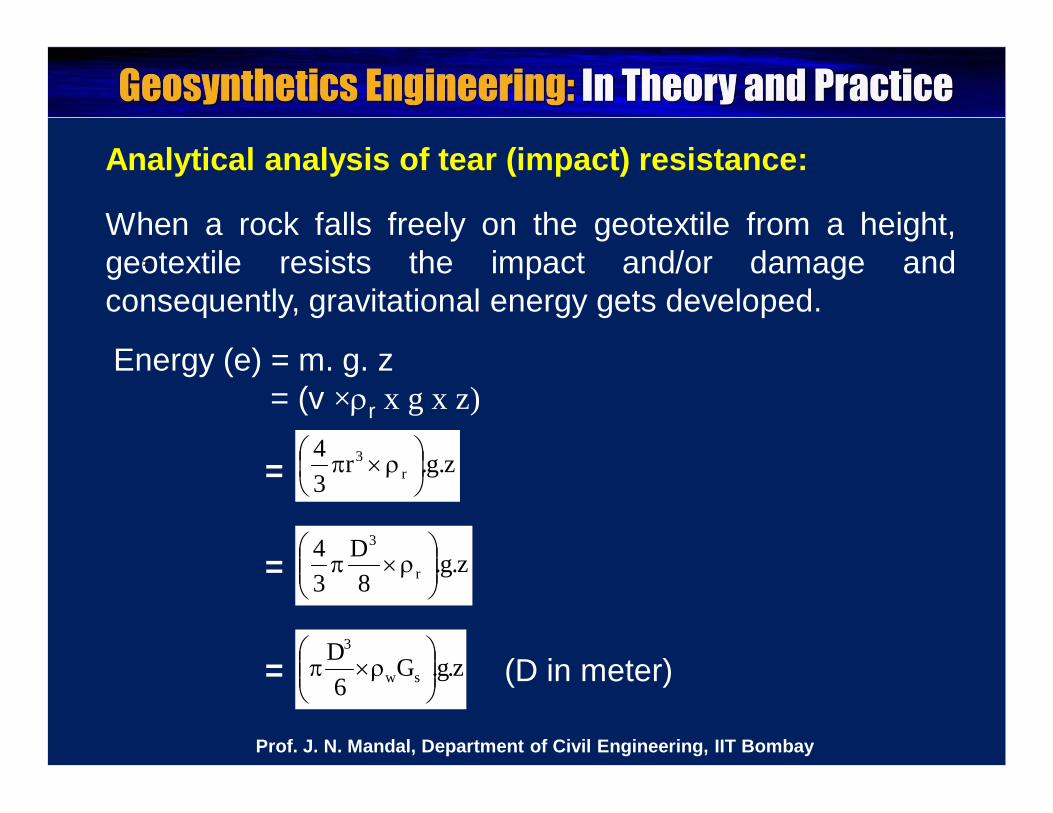
Analytical analysis of tear (impact) resistance:
When a rock falls freely on the geotextile from a height,geotextile resists the impact and/or damage andconsequently, gravitational energy gets developed.
z.g.r34
r3
z.g.8
D34
r
3
z.g.G6
Dsw
3
Energy (e) = m. g. z = (v ×r x g x z)
=
=
=
= (D in meter)
Prof. J. N. Mandal, Department of Civil Engineering, IIT Bombay
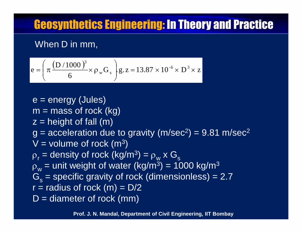
e = energy (Jules)m = mass of rock (kg)z = height of fall (m)g = acceleration due to gravity (m/sec2) = 9.81 m/sec2
V = volume of rock (m3)r = density of rock (kg/m3) = w x Gsw = unit weight of water (kg/m3) = 1000 kg/m3
Gs = specific gravity of rock (dimensionless) = 2.7r = radius of rock (m) = D/2D = diameter of rock (mm)
z D 10 13.87 z.g.G6
1000/De 36-sw
3
When D in mm,
Prof. J. N. Mandal, Department of Civil Engineering, IIT Bombay
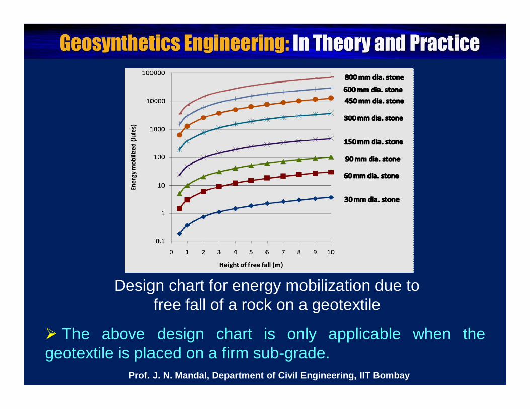
Design chart for energy mobilization due to free fall of a rock on a geotextile
The above design chart is only applicable when thegeotextile is placed on a firm sub-grade.
Prof. J. N. Mandal, Department of Civil Engineering, IIT Bombay
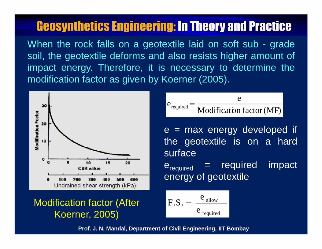
When the rock falls on a geotextile laid on soft sub - gradesoil, the geotextile deforms and also resists higher amount ofimpact energy. Therefore, it is necessary to determine themodification factor as given by Koerner (2005).
Modification factor (After Koerner, 2005)
)MF(factoronModificatieerequired
required
allow
ee.S.F
e = max energy developed ifthe geotextile is on a hardsurfaceerequired = required impactenergy of geotextile
Prof. J. N. Mandal, Department of Civil Engineering, IIT Bombay
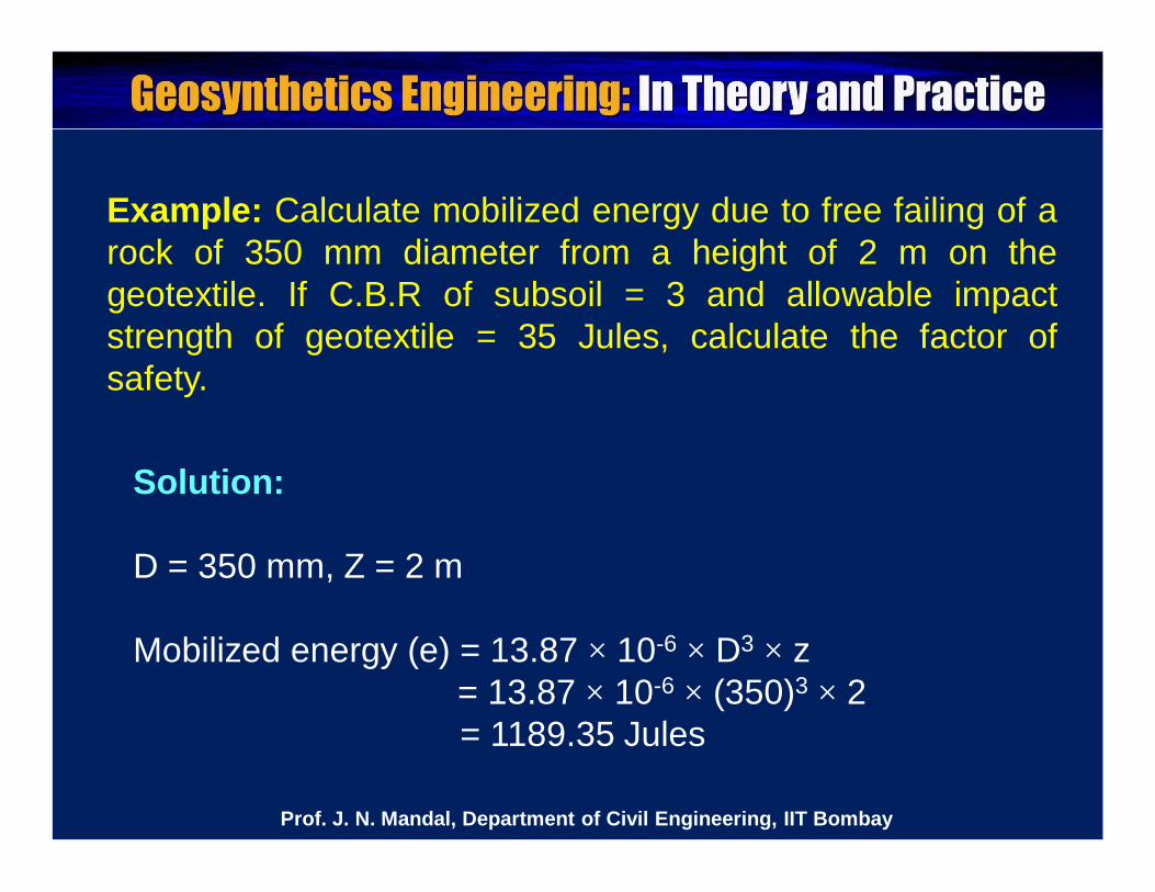
Example: Calculate mobilized energy due to free failing of arock of 350 mm diameter from a height of 2 m on thegeotextile. If C.B.R of subsoil = 3 and allowable impactstrength of geotextile = 35 Jules, calculate the factor ofsafety.
Solution:
D = 350 mm, Z = 2 m
Mobilized energy (e) = 13.87 × 10⁻⁶ × D3 × z= 13.87 × 10-6 × (350)3 × 2= 1189.35 Jules
Prof. J. N. Mandal, Department of Civil Engineering, IIT Bombay
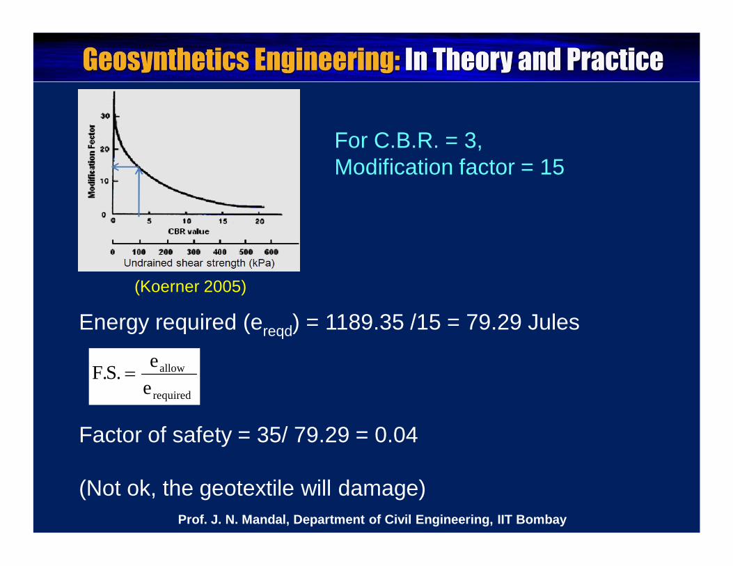
Energy required (ereqd) = 1189.35 /15 = 79.29 Jules
For C.B.R. = 3, Modification factor = 15
required
allow
ee.S.F
Factor of safety = 35/ 79.29 = 0.04
(Not ok, the geotextile will damage)
(Koerner 2005)
Prof. J. N. Mandal, Department of Civil Engineering, IIT Bombay
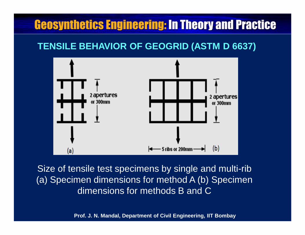
TENSILE BEHAVIOR OF GEOGRID (ASTM D 6637)
Size of tensile test specimens by single and multi-rib (a) Specimen dimensions for method A (b) Specimen
dimensions for methods B and C
Prof. J. N. Mandal, Department of Civil Engineering, IIT Bombay
For geogrid wide width method B and C, minimum widthof the sample contains 5 ribs or is 200 ± 3 mm and lengthof the sample contains 2 apertures/ 3 junctions or is 300mm.
The test is to be conducted in a tensile testing machineat a strain rate of 10 ± 3 % per minute.
Using hydraulic clamping grips, tensile strength ofgeosynthetic can be measured in between 30 and 120kN/m.
If the tensile strength is more than 120 kN/m, roller gripsare generally used.
Prof. J. N. Mandal, Department of Civil Engineering, IIT Bombay
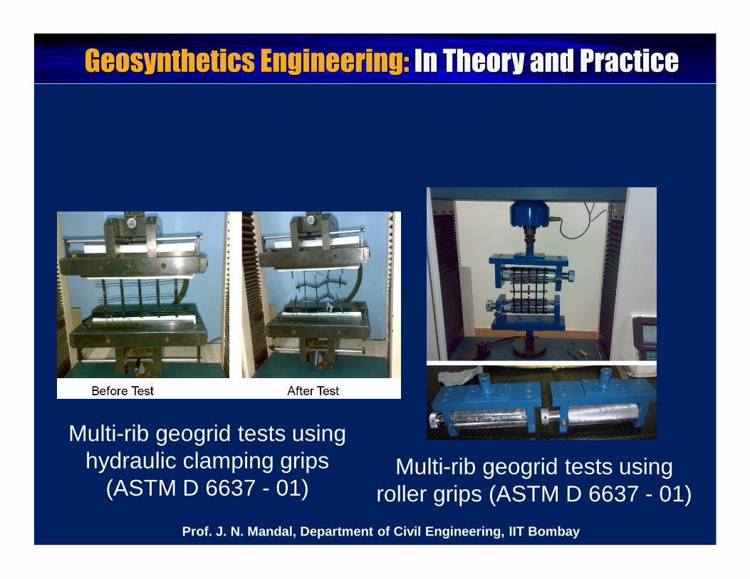
Multi-rib geogrid tests using hydraulic clamping grips
(ASTM D 6637 - 01)Multi-rib geogrid tests using
roller grips (ASTM D 6637 - 01)Prof. J. N. Mandal, Department of Civil Engineering, IIT Bombay
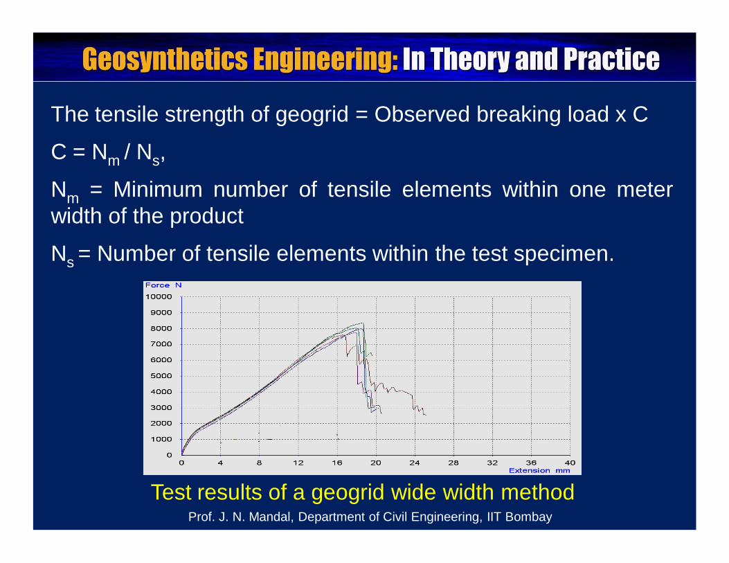
The tensile strength of geogrid = Observed breaking load x C
C = Nm / Ns,
Nm = Minimum number of tensile elements within one meterwidth of the product
Ns = Number of tensile elements within the test specimen.
Test results of a geogrid wide width methodProf. J. N. Mandal, Department of Civil Engineering, IIT Bombay
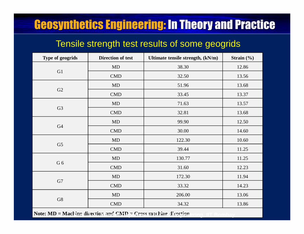
Tensile strength test results of some geogridsType of geogrids Direction of test Ultimate tensile strength, (kN/m) Strain (%)
G1MD 38.30 12.86
CMD 32.50 13.56
G2MD 51.96 13.68
CMD 33.45 13.37
G3MD 71.63 13.57
CMD 32.81 13.68
G4MD 99.90 12.50
CMD 30.00 14.60
G5MD 122.30 10.60
CMD 39.44 11.25
G 6MD 130.77 11.25
CMD 31.60 12.23
G7MD 172.30 11.94
CMD 33.32 14.23
G8MD 206.00 13.06
CMD 34.32 13.86
Note: MD = Machine direction and CMD = Cross machine directionProf. J. N. Mandal, Department of Civil Engineering, IIT Bombay
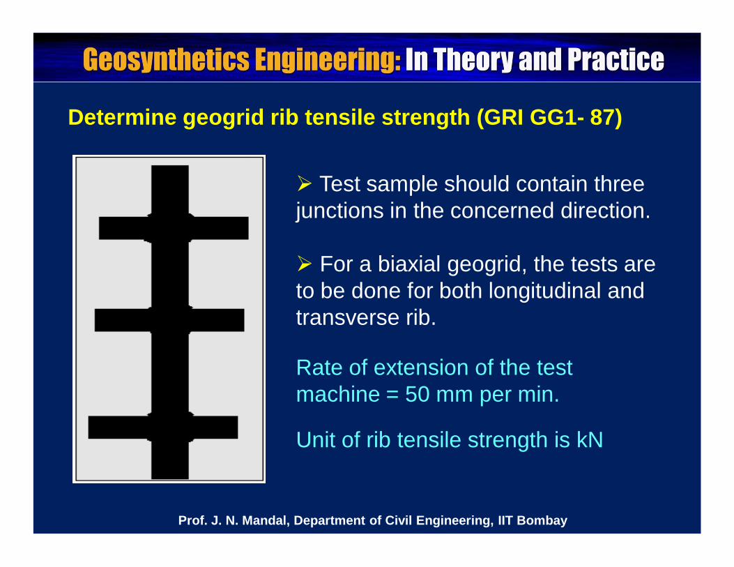
Determine geogrid rib tensile strength (GRI GG1- 87)
Rate of extension of the test machine = 50 mm per min.
Test sample should contain three junctions in the concerned direction.
For a biaxial geogrid, the tests are to be done for both longitudinal and transverse rib.
Unit of rib tensile strength is kN
Prof. J. N. Mandal, Department of Civil Engineering, IIT Bombay

Trib = (Σ Ti)/N
Ti = Ultimate test strength of each rib (kN), and
N = Total number of test specimens (minimum of 10)
Tgrid = (Trib) (nrib) / L
Tgrid = Ultimate strength of geogrid (kN/m)
nrib = Number of ribs in length L (Typically taken over onemeter length)
L = length used to determine number of ribs in a meter.
Prof. J. N. Mandal, Department of Civil Engineering, IIT Bombay
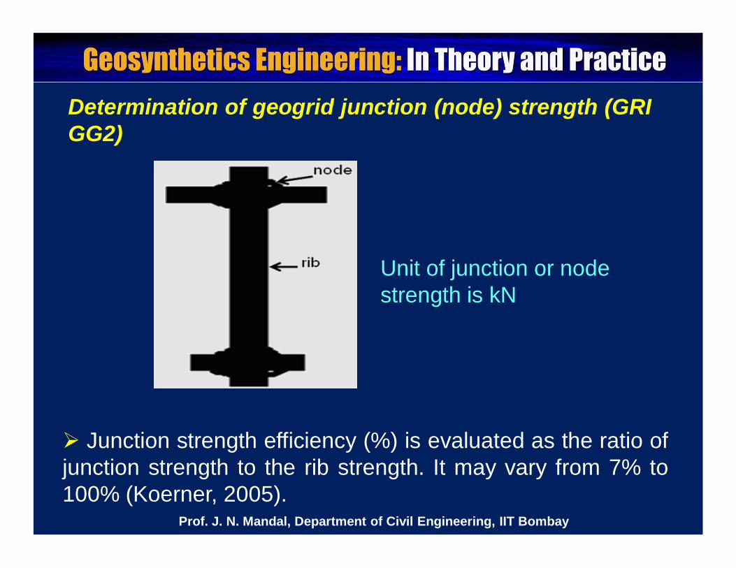
Determination of geogrid junction (node) strength (GRIGG2)
Unit of junction or node strength is kN
Junction strength efficiency (%) is evaluated as the ratio ofjunction strength to the rib strength. It may vary from 7% to100% (Koerner, 2005).
Prof. J. N. Mandal, Department of Civil Engineering, IIT Bombay
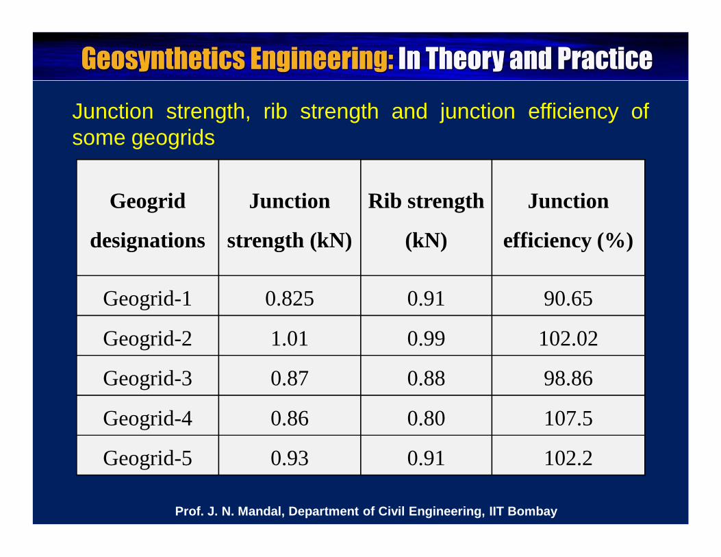
Junction strength, rib strength and junction efficiency ofsome geogrids
Geogrid
designations
Junction
strength (kN)
Rib strength
(kN)
Junction
efficiency (%)
Geogrid-1 0.825 0.91 90.65
Geogrid-2 1.01 0.99 102.02
Geogrid-3 0.87 0.88 98.86
Geogrid-4 0.86 0.80 107.5
Geogrid-5 0.93 0.91 102.2
Prof. J. N. Mandal, Department of Civil Engineering, IIT Bombay
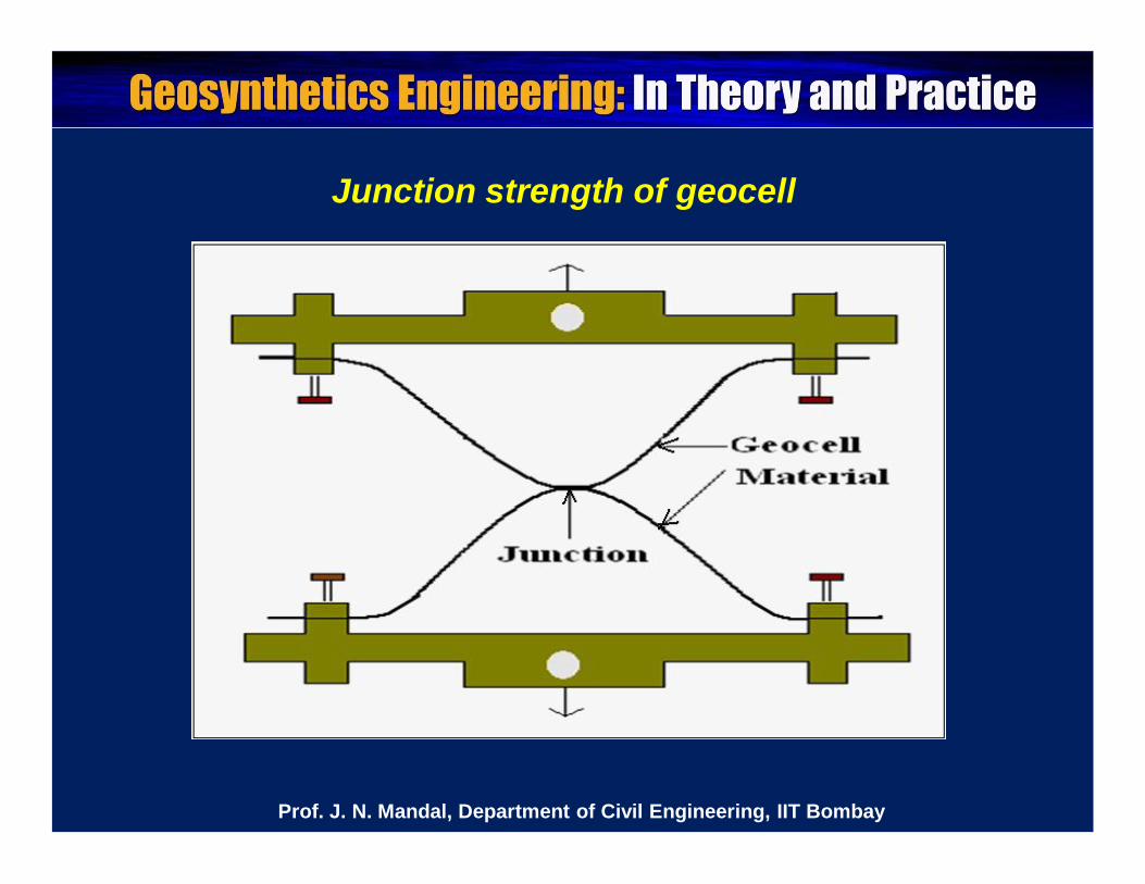
Junction strength of geocell
Prof. J. N. Mandal, Department of Civil Engineering, IIT Bombay
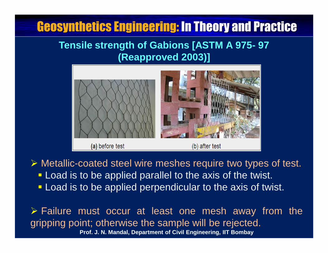
Tensile strength of Gabions [ASTM A 975- 97 (Reapproved 2003)]
Metallic-coated steel wire meshes require two types of test. Load is to be applied parallel to the axis of the twist. Load is to be applied perpendicular to the axis of twist.
Failure must occur at least one mesh away from thegripping point; otherwise the sample will be rejected.
Prof. J. N. Mandal, Department of Civil Engineering, IIT Bombay
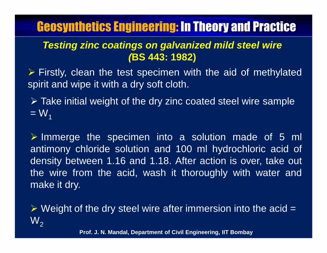
Testing zinc coatings on galvanized mild steel wire (BS 443: 1982)
Take initial weight of the dry zinc coated steel wire sample = W1
Immerge the specimen into a solution made of 5 mlantimony chloride solution and 100 ml hydrochloric acid ofdensity between 1.16 and 1.18. After action is over, take outthe wire from the acid, wash it thoroughly with water andmake it dry.
Weight of the dry steel wire after immersion into the acid = W2
Firstly, clean the test specimen with the aid of methylatedspirit and wipe it with a dry soft cloth.
Prof. J. N. Mandal, Department of Civil Engineering, IIT Bombay
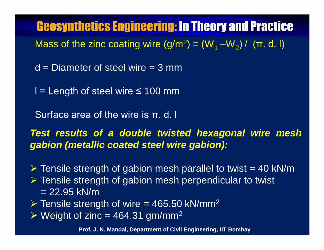
Mass of the zinc coating wire (g/m2) = (W1 –W2) / (π. d. l)
d = Diameter of steel wire = 3 mm
l = Length of steel wire ≤ 100 mm
Surface area of the wire is π. d. l
Test results of a double twisted hexagonal wire meshgabion (metallic coated steel wire gabion):
Tensile strength of gabion mesh parallel to twist = 40 kN/m Tensile strength of gabion mesh perpendicular to twist
= 22.95 kN/m Tensile strength of wire = 465.50 kN/mm2
Weight of zinc = 464.31 gm/mm2
Prof. J. N. Mandal, Department of Civil Engineering, IIT Bombay
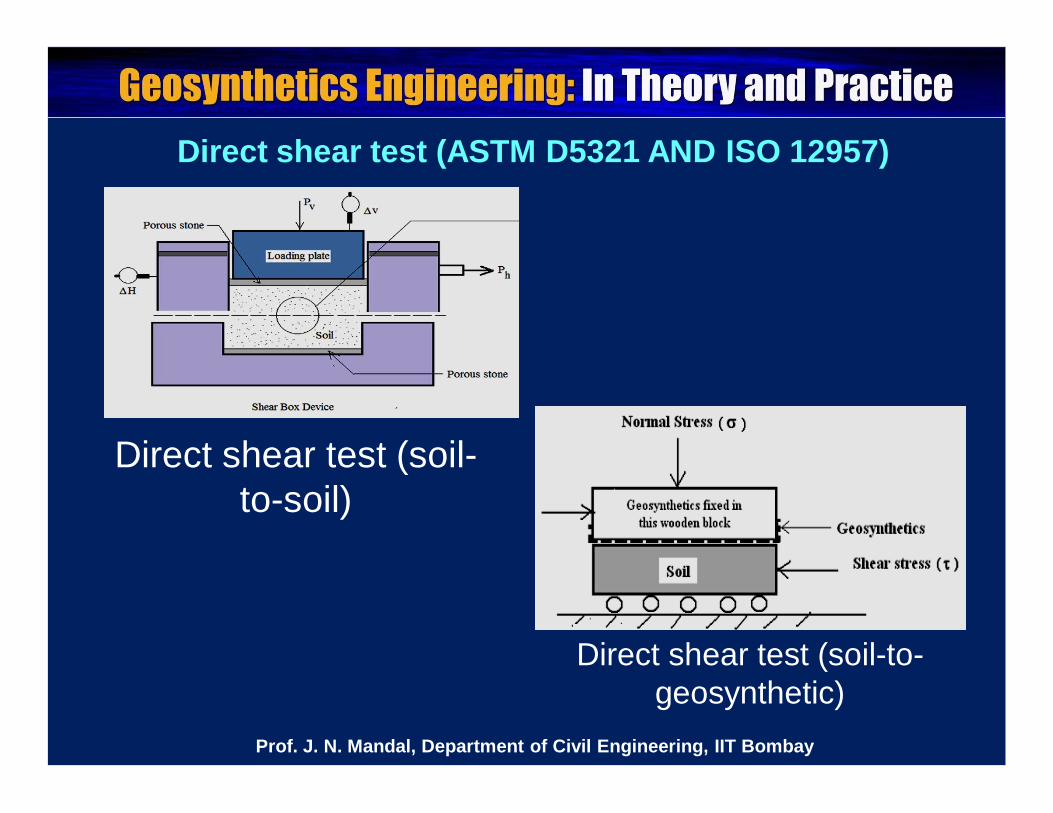
Direct shear test (ASTM D5321 AND ISO 12957)
Direct shear test (soil-to-soil)
Direct shear test (soil-to-geosynthetic)
Prof. J. N. Mandal, Department of Civil Engineering, IIT Bombay
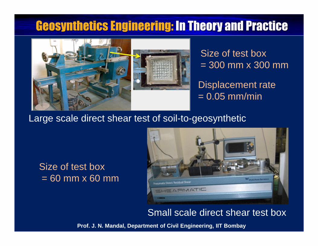
Small scale direct shear test box
Size of test box= 60 mm x 60 mm
Large scale direct shear test of soil-to-geosynthetic
Size of test box= 300 mm x 300 mm
Displacement rate = 0.05 mm/min
Prof. J. N. Mandal, Department of Civil Engineering, IIT Bombay
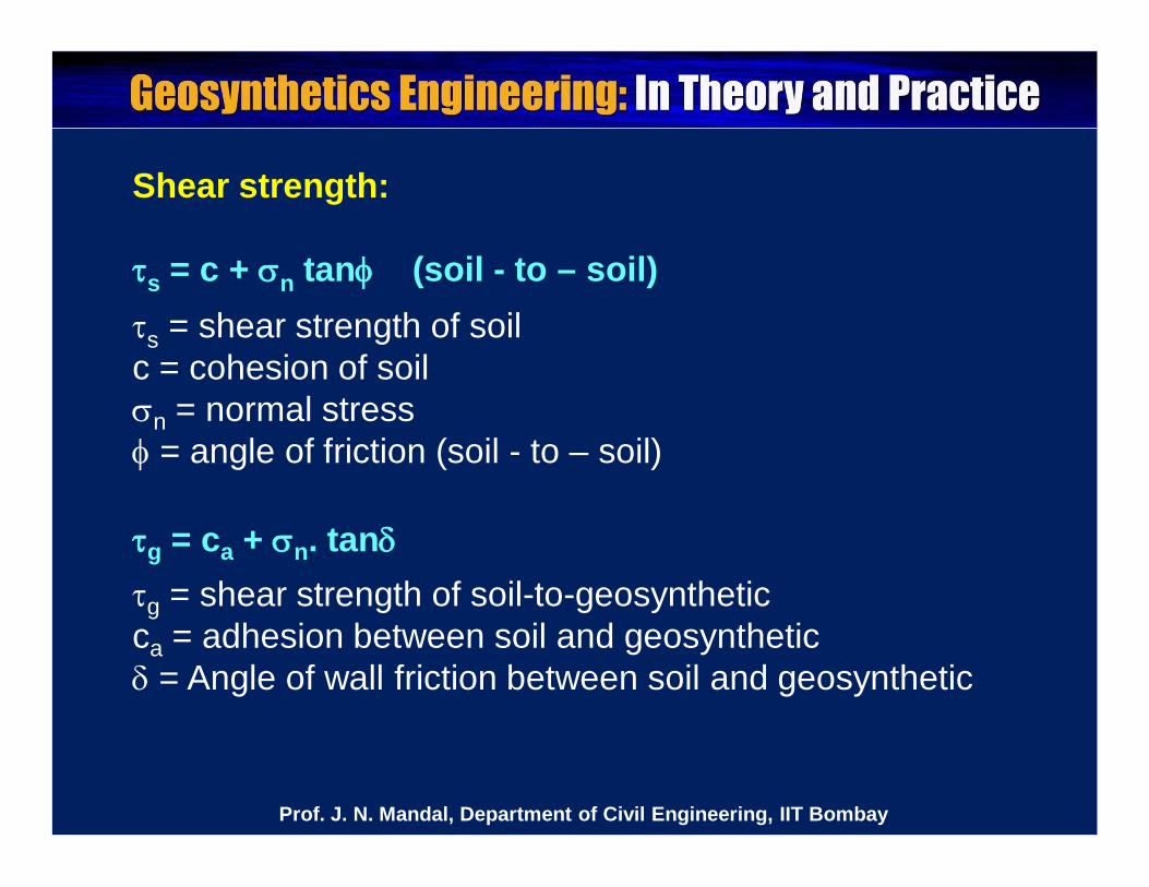
Shear strength:
s = c + n tan (soil - to – soil)s = shear strength of soilc = cohesion of soiln = normal stress = angle of friction (soil - to – soil)
g = ca + n. tang = shear strength of soil-to-geosynthetic ca = adhesion between soil and geosynthetic = Angle of wall friction between soil and geosynthetic
Prof. J. N. Mandal, Department of Civil Engineering, IIT Bombay
100xc
c ac
100xtantan
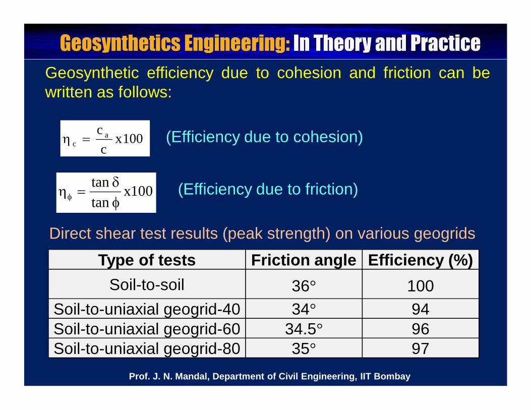
Geosynthetic efficiency due to cohesion and friction can bewritten as follows:
(Efficiency due to cohesion)
(Efficiency due to friction)
Type of tests Friction angle Efficiency (%)Soil-to-soil 36° 100
Soil-to-uniaxial geogrid-40 34° 94Soil-to-uniaxial geogrid-60 34.5° 96Soil-to-uniaxial geogrid-80 35° 97
Direct shear test results (peak strength) on various geogrids
Prof. J. N. Mandal, Department of Civil Engineering, IIT Bombay
Minimum width of geogrid (Wg) should be as follows toobtain the highest efficiency,
Wg > 3.5 d50 (Sarsby, 1985)
d50 = average size of the backfill material
Prof. J. N. Mandal, Department of Civil Engineering, IIT Bombay

Please let us hear from you
Any question?
Prof. J. N. Mandal, Department of Civil Engineering, IIT Bombay

Prof. J. N. Mandal
Department of civil engineering, IIT Bombay, Powai , Mumbai 400076, India. Tel.022-25767328email: [email protected]
Prof. J. N. Mandal, Department of Civil Engineering, IIT Bombay