Embed Size (px)
Citation preview

Geostructural Solutions

About Nucor Skyline
Nucor Skyline, your true project partnerWe are a premier steel foundation manufacturer and supplier, serving the North American market. Skyline Steel, LLC is a Nucor company, the largest producer of steel in the United States, and this relationship strengthens our ability to service our customers and the industry.
• Over 20 Sales Offices in North America
• Manufacturing, Coating and Fabrication Expertise
• Dozens of Stocking Locations
• Exclusive Engineering Support
Our flagship products include an unparalleled assortment of:
• H-Piles • Geostructural Products
• Steel Sheet Piles • Structural Sections
• Pipe Piles • Piling Accessories
Nucor Skyline’s knowledgeable engineering team works with owners, engineers, and contractors long before ground is broken. To ensure seamless project coordination and completion, our engineers propose solutions throughout all aspects of design, material selection, installation, and construction sequencing. Skyline’s engineering support is extended even further to include provision of onsite assistance after a project has started. Our relationships extends beyond sales – we are your true project partner.

As a premier supplier and manufacturer of steel foundation products, we are proud to offer our comprehensive line of geostructural products. Nucor Skyline’s geostructural business unit has become a leader in the supply side of the heavy civil construction business.
We have a core group of geostructural industry specialists dedicated to providing superior service to this growing market. A significant investment in manufacturing has been made which allows us to continue to add new product lines and strengthen our existing product offering. In addition to Nucor Skyline’s complete line of grade 75 and grade 150 cold rolled threaded bar, we offer an improved hot rolled threaded bar. Our manufacturing capabilities have also been expanded to allow us to produce DCP shop grouted and SCP ground anchors in multiple locations across the United States. Nucor Skyline’s experienced production team are experts at assembling large-scale reinforcement bar cages, using couplers and full load nuts, measuring over 65 feet long.
Significant improvements have also been made in our micropile manufacturing capabilities. Micropile threaded casing production capacity has been expanded to further supplement our full line of bar reinforcing products, making us the single source supplier to any contractor involved in a micropile project. Multi-strand anchors, featuring Samwoo load distributive anchor systems with removable capabilities, are exclusively available from Nucor Skyline. A comprehensive hollow bar system with a full line of complementary accessories has also been added to our geostructural product offering. Nucor Skyline is pleased to be a market leader in the specialty products described in this brochure and we are dedicated to partnering with our customers and delivering high quality products and cost effective solutions.
Table of Contents
PRODUCT DATA
Cold Rolled Threaded Bars . . . . . . . . . 2
Hot Rolled Threaded Bars . . . . . . . . . 10
Hollow Bar Systems . . . . . . . . . . . . . . 12
Threaded Casing for Micropiles . . . . 18
Multi-Strand Anchor Systems . . . . . . 20
PRODUCT DETAIL
Hollow Bar Systems . . . . . . . . . . . . . . 16
Multi-Strand Anchor Systems . . . . . . 21
TYPICAL GEOSTRUCTURAL APPLICATIONS
Ground Anchors . . . . . . . . . . . . . . . . . 26
Rock Bolts/Anchor Bolts . . . . . . . . . . 31
Soil Nails . . . . . . . . . . . . . . . . . . . . . . . 32
Tie Rods . . . . . . . . . . . . . . . . . . . . . . . 34
Micropiles . . . . . . . . . . . . . . . . . . . . . . 46
Pile Reinforcement . . . . . . . . . . . . . . 48
Geostructural Solutions from Nucor Skyline

2 Nucor Skyline: Geostructural Solutions Please note: As we continuously improve the design of our products, product details are subject to change.
Cold Rolled Threaded Bars†
Threaded Bars and Accessories
† Contact your sales representative for information on hot dip galvanized and epoxy coated bars.
Bar Designation
Nominal Diameter
inmm
GradeMin. Net Area Thru Threads
in2
mm2
Min. Ultimate Strength
kipskN
Min. Yield Strength
kipskN
Nominal Weight
lbs/ftkg/m
Approx. Major Thread Diameter
inmm
Thread Orientation
Max. Length
ftm
#8 1 25
75 0.790510.0
79.0351.4
59.3263.8
2.704.0
1.12528.5
Left Hand 6018.3
80 0.790510.0
83.0369.2
63.2281.1
2.704.0
1.12528.5
Left Hand 6018.3
#9 1 1/8 28
75 1.000645.0
100.0444.8
75.0333.6
3.405.1
1.25032.0
Left Hand 6018.3
80 1.000645.0
105.0467.1
80.0355.9
3.405.1
1.25032.0
Left Hand 6018.3
#10 1 1/432
75 1.270819.0
127.0564.9
95.3423 .9
4.306.4
1.37535.0
Left Hand 6018.3
80 1.270819.0
133.4593.4
101.6451.9
4.306.4
1.37535.0
Left Hand 6018.3
#11 1 3/8 35
75 1.5601006.0
156.0694.0
117.0520.5
5.307.9
1.50038.1
Left Hand 6018.3
80 1.5601006.0
163.8728.6
124.8555.1
5.307.9
1.50038.1
Left Hand 6018.3
#14 1 3/4 45
75 2.2501452.0
225.01000.9
168.7750.4
7.6511.4
1.87547.6
Right Hand 6018.3
80 2.2501452.0
236.31051.1
180.0800.7
7.6511.4
1.87547.6
Right Hand 6018.3
#18 2 1/455
75 4.0002581.0
400.01779.4
300.01334.5
13.6020.2
2.438 62.0
Right Hand 6018.3
80 4.0002581.0
420.01868.2
320.01423.4
13.6020.2
2.438 62.0
Right Hand 6018.3
#20 2 1/264
75 4.9103168.0
491.02184.0
368.01637.0
16.6924.8
2.75070.0
Right Hand 6018.3
80 4.9103168.0
515.62293.5
392.81747.3
16.6924.8
2.75070.0
Right Hand 6018.3
#24 376
75 7.0704561.0
707.03142.0
530.02356.0
24.1035.9
3.250 82.6
Right Hand 6018.3
80 7.0704561.0
742.43302.3
565.62515.9
24.1035.9
3.250 82.6
Right Hand 6018.3
#28 3 1/2 89
75 9.6106200.0
960.04274.0
720.03206.0
32.7048.7
3.75095.3
Right Hand 6018.3
80 9.6106200.0
1009.14488.7
768.83419.8
32.7048.7
3.75095.3
Right Hand 6018.3
Cold rolled threaded bars conform to the physical and chemical requirements of ASTM A 615 Grade 75 ksi “Standard Specification for Deformed Carbon Steel Bars for Concrete Reinforcement”* Contact your local Nucor Skyline representative for information on additional steel grades.
Approx. MajorThread Diameter

Nucor Skyline: Geostructural Solutions 3Please note: As we continuously improve the design of our products, product details are subject to change.
Cold Rolled Threaded Bars†
† Contact your sales representative for information on hot dip galvanized and epoxy coated bars.
Approx. MajorThread Diameter
Threaded Bars and Accessories
Nominal Diameter
inmm
GradeMin. Net Area Thru Threads
in2
mm2
Min. Ultimate Strength
kipskN
Min. Yield Strength
kipskN
Nominal Weight
lbs/ftkg/m
Approx. Major Thread Diameter
inmm
Thread Orientation
Max. Length
ftm
126
150 0.850549
128567
102454
3.14.6
1 1/828.6
Left Hand 6018.3
1 1/432
150 1.250807
188834
150667
4.56.7
1 1/238.1
Left Hand 6018.3
1 3/836
150 1.5801019
2371054
190843
5.78.5
1 5/841.3
Left Hand 6018.3
1 3/446
150 2.6001677
3901735
3201423
9.113.5
250.8
Left Hand 6018.3
2 1/457
150 4.0002581
6002669
4802135
13.620.2
2 7/1662.0
Left Hand 6018.3
2 1/265
150 5.1903350
7783457
6222766
18.327.2
2 3/469.9
Left Hand 6018.3
375
150 7.0604554
10594702
8473766
24.035.7
3 1/482.6
Left Hand 6018.3
1 inch to 1 3/8 inch diameter, ASTM A 722; 1 3/4 inch to 3 inch diameter bar manufactured in accordance with ASTM A 722 physical and chemical requirements. Grade 150 ksi steel must not be subjected to localized heating such as welding, cutting torch, or hot grinding.

4 Nucor Skyline: Geostructural Solutions Please note: As we continuously improve the design of our products, product details are subject to change.
Cold Rolled Threaded Bar Accessories†
† Contact your sales representative for information on hot dip galvanized and epoxy coated bars.
L
OD
Full Load Hex Nut Jam Nut
A B A C
Threaded Bars and Accessories
Threaded Bar Connectors
Grade 75 Bar
Bar Designation
OD
inmm
L
inmm
Weight
lbskg
#81.62541.3
4.500114.3
1.550.70
#91.87547.6
5.000127.0
2.391.08
#102.12554.0
5.500139.7
3.471.57
#112.25057.2
6.000152.4
4.021.82
#142.87573.0
7.875200.0
9.164.15
#183.50088.9
9.125231.8
13.936.32
#204.000101.6
9.500241.3
19.869.01
#244.750120.6
10.750243.0
31.0114.07
#285.500139.7
12.000304.8
46.2020.96
Grade 150 Bar
Nominal Diameter
inmm
OD
inmm
L
inmm
Weight
lbskg
126
1.75044.5
4.250108.0
1.700.77
1 1/432
2.12554.0
5.250133.4
3.111.41
1 3/836
2.37560.3
5.750146.1
4.221.91
1 3/446
3.00076.2
8.500215.9
9.984.53
2 1/457
4.000101.6
9.000228.6
21.459.73
2 1/265
4.250108.0
10.000254.0
23.9610.87
375
5.000127.0
12.000308.0
41.2418.71
Full Load Hex Nuts and Jam Nuts
Grade 75 Bar
Bar Designation
A
inmm
B
inmm
C
inmm
Weight
lbskg
Full Jam
#81.62541.3
2.00050.8
0.50012.7
0.810.37
0.200.09
#91.75044.5
2.00050.8
0.56314.3
0.890.40
0.250.11
#102.00050.8
2.18755.5
0.62515.9
1.330.60
0.380.17
#112.25057.2
2.50063.5
0.68817.5
1.960.89
0.540.24
#142.75069.9
3.25082.6
0.93823.8
3.861.75
1.110.50
#183.50089.0
3.50089.0
1.00025.4
4.872.21
1.810.82
#20*4.000101.6
4.500114.3
1.12528.6
9.834.46
2.761.25
#24**4.750120.6
4.500114.3
1.50038.1
12.985.89
4.331.96
#28**5.500139.7
6.000152.4
1.56339.7
23.1010.48
6.022.73
*Round collar nut available **Round collar nut with flats
Grade 150 Bar
Nominal Diameter
inmm
A
inmm
B
inmm
C
inmm
Weight
lbskg
Full Jam
126
1.75044.5
2.00050.8
0.50012.7
0.940.43
0.230.10
1 1/432
2.25057.2
2.50063.5
0.62515.9
2.070.94
0.520.24
1 3/836
2.50063.5
2.75069.9
0.75019.1
2.781.26
0.750.34
1 3/446
3.00076.2
3.50088.9
1.25031.8
4.832.19
1.700.77
2 1/457
4.000101.6
4.250107.95
1.50038.10
11.685.30
4.091.86
2 1/265
4.000101.6
4.750120.7
1.75044.45
10.824.91
3.991.81
375
5.000127.0
6.000152.4
2.00050.8
20.629.35
5.112.32

Nucor Skyline: Geostructural Solutions 5Please note: As we continuously improve the design of our products, product details are subject to change.
Cold Rolled Threaded Bar Accessories
Contact your local Nucor Skyline representative for information on additional grades of steel.
AB C
A C
BEVEL
D
B
Threaded Bars and Accessories
Hardened Washers
Grade 75 Bar
Bar Designation A
inmm
B
inmm
C
inmm
Weight
lbskg
#82.25057.150
1.18830.175
0.1363.454
0.1100.05
#92.50063.500
1.37534.925
0.1363.454
0.1300.06
#102.75069.850
1.53138.887
0.1363.454
0.1600.07
#113.00076.200
1.62541.275
0.1363.454
0.1900.09
#143.750
95.2502.125
53.9750.1784.521
0.3800.17
#184.500114.300
2.65767.488
0.2406.096
0.7100.32
#205.500
139.7003.15780.188
0.2406.096
1.0900.49
#246.000
152.4003.62592.075
0.3759.525
1.9100.87
#287.000
177.8004.125
104.7750.3759.525
2.6801.22
Grade 150 Bar
Nominal Diameter
inmm
A
inmm
B
inmm
C
inmm
Weight
lbskg
126
2.50063.500
1.37534.925
0.1363.454
0.1300.06
1 1/432
2.75069.850
1.53138.887
0.1363.454
0.1600.07
1 3/836
3.25082.550
1.77044.958
0.1784.521
0.3000.13
1 3/446
4.000101.600
2.40761.138
0.2406.096
0.5500.25
2 1/457
4.500114.300
2.65767.488
0.2406.096
0.7100.32
2 1/265
5.500139.700
3.15780.188
0.2406.096
1.0900.49
375
6.000152.400
3.62592.075
0.3759.525
1.9100.87
Round Beveled Washers
Grade 75 Bar
Bar Designation
A
inmm
B
inmm
C
inmm
D
inmm
Bevel
degreesWeight
lbskg
#81.75
44.451.13
28.580.4611.68
0.174.32
9.40.210.10
#92.6366.68
1.3831.75
0.9323.62
0.235.84
150.690.31
#102.75
69.851.6341.40
0.9724.64
0.235.84
150.660.30
#113.0978.49
1.7544.45
1.0626.92
0.235.84
150.930.45
#144.00
101.602.1354.10
1.2932.77
0.235.84
151.940.88
#184.60
116.842.63
66.801.18
29.970.379.40
102.461.12
#205.00
127.003.0076.20
1.3133.27
0.4310.92
103.101.41
#248.00
203.203.5088.90
1.7544.45
0.4310.92
1012.585.71
#288.00
203.204.00
101.602.2557.15
0.8421.34
1016.547.50
Grade 150 Bar
Nominal Diameter
inmm
A
inmm
B
inmm
C
inmm
D
inmm
Bevel
degreesWeight
lbskg
126
2.6366.68
1.2531.75
0.9323.62
0.235.84
150.690.31
1 1/432
2.7569.85
1.6341.40
0.9724.64
0.235.84
150.660.30
1 3/836
3.0978.49
1.7544.45
1.0626.92
0.235.84
150.930.42
1 3/446
4.00101.60
2.1354.10
1.2932.77
0.235.84
151.940.88
2 1/457
4.60116.84
2.6366.80
1.1829.97
0.379.40
102.461.12
2 1/264
5.00127.00
3.0076.20
1.3133.27
0.4310.92
103.101.41
375
8.00203.20
3.5088.90
1.7544.45
0.4310.92
1012.585.71

6 Nucor Skyline: Geostructural Solutions Please note: As we continuously improve the design of our products, product details are subject to change.
Cold Rolled Threaded Bar Accessories
Threaded Bars and Accessories
Bearing Plates
Bearing plate dimensions reflect typical sizes. Actual design criteria should be used for specific plate sizing.
Grade 75 Bar
Bar Designation
A
inmm
B
inmm
C
inmm
Weight
lbskg
#88
203.208
203.203/4
19.0513.406.08
#98
203.208
203.203/4
19.0513.356.06
#108
203.208
203.201
25.4017.738.04
#1110
254.0010
254.001
25.4027.8612.64
#1410
254.0010
254.001 1/2
38.1041.3718.76
#1810
254.0010
254.002
50.8054.2124.59
#2010
254.0010
254.002 1/2
63.5067.0630.42
#2410
254.0010
254.002 1/2
63.5065.4629.69
#2812
304.8012
304.802 3/4
69.85104.2647.29
Grade 150 Bar
Nominal Diameter
inmm
A
inmm
B
inmm
C
inmm
Weight
lbskg
126
6152.4
6152.4
1 1/431.8
12.765.79
1 1/432
7177.8
7177.8
1 1/238.1
20.849.45
1 3/836
8203.2
8203.2
1 3/444.5
31.7614.41
1 3/446
9228.6
9228.6
1 3/444.5
40.2018.23
2 1/457
10254.0
10254.0
2 1/263.5
70.8932.16
2 1/265
10254.0
10254.0
2 1/263.5
70.8932.16
375
12304.8
12304.8
2 3/469.9
112.3150.94
Anchor Nuts†
Grade 150 Anchor Nuts
Diameter
inmm
A
inmm
L
inmm
N
inmm
Weight
lbskgs
126
1.75044.5
2.360 59.9
2.4562.2
1.440.65
1 1/432
2.125 54.0
3.12579.5
3.1580.0
3.03 1.37
1 3/836
2.375 60.3
3.37585.9
3.588.9
4.05 1.84
1 3/446
3.000 76.2
4.000101.6
4.2106.7
7.05 3.20
2 1/457
4.250 108.0
5.500139.7
5.6142.2
20.24 9.18
† Consult your sales representative for availability of additional threads and grades.
HDPE Plastic Nut Caps*
Plastic Nut Caps for Grade 75 Bars
Bar Designation
A
inmm
B
inmm
C
inmm
#8 – #113.588.9
2.2557.2
6.75171.5
#14 – #286.5165.1
4.25108.0
10.25260.4
Plastic Nut Caps for Grade 150 Bars
Nominal Diameter
inmm
A
inmm
B
inmm
C
inmm
1 – 1 3/826 – 36
3.588.9
2.2557.2
6.75171.5
1 3/4 – 346 – 75
6.5165.1
4.25108.0
10.25260.4
* “O” ring seal in base of cap.
B
A
C
A
L
N
SECTION B
SECTION BB
C
ASECTION A
SECTION A

Nucor Skyline: Geostructural Solutions 7Please note: As we continuously improve the design of our products, product details are subject to change.
Threaded Bars and Accessories
All threaded bars can be supplied with a protective smooth-walled PVC tube. While the standard PVC tube is 0.035 inch thick, other options are available upon request.
The following additional corrosion protection options are available for all threaded bars:
Single Corrosion Protection (SCP)
Double Corrosion Protection (DCP)
• Encapsulating: Grease or Grout • Epoxy Coating• Galvanizing• Painting• Plating• Taping
Oversized accessories are provided to accommodate galvanized and coated bars.
Please contact your Nucor Skyline Geostructural Solutions Representative for recommendations on the system that will best suit your requirements.
Corrosion Protection
Cold Rolled Threaded Bar Accessories
Forged Eye
Bar Designation
A
inmm
B
inmm
C
inmm
D
inmm
E
inmm
F
inmm
#146.1155
2.563
2.460
19.9505
8.1207
2.050
#186.1155
2.563
2.460
19.9505
8.1207
2.050
#207.1
1803.076
3.076
20.5520
9.8248
2.563
#247.1
1803.076
3.076
20.5520
9.8248
2.563
#289.2230
3.588
3.590
22.2565
12.3312
3.075
Threads on forged eye will be metric. Conversion couplers available (transition) for all Nucor Skyline thread forms.
Contact your Nucor Skyline sales representative for assistance with connection details.
Transitional Coupler for Forged Eye
Bar Designation
OD
inmm
L
inmm
X
inmm
Y
inmm
Weight
lbkg
M56 – #143.5088.90
9.8248.92
4.00101.6
4.57116.0
18.48.4
M56 – #183.5088.90
9.8248.92
4.00101.6
4.57116.0
15.67.1
M72 – #204.75
120.6512.0
304.805.38136.5
5.38136.5
39.217.8
M72 – #244.75
120.6512.0
304.805.38136.5
5.38136.5
34.915.8
M85 – #285.50
139.7013.3
337.826.00152.4
6.00152.4
48.522.0
D
E
F
A
B
C
Threaded Portion
Threaded Portion
MetricThread Form
X
OD
LY
Skyline SteelThread Form

8 Nucor Skyline: Geostructural Solutions Please note: As we continuously improve the design of our products, product details are subject to change.
Threaded Bars and Accessories
Tie Bars without Articulation
Normal End Threads Upset Forged Threads
Bar
Thread Diameter
Shaft Diameter
Thread ShaftRecommended
Design CapacityTensile Stress Area
Yield Capacity
Ultimate Capacity
Gross Area
Yield Capacity
Ultimate Capacity
DT
Dg
As
Thy
Thu
Ag
Shy
Shu
ASD* LRFD*
inmm
inmm
in2
mm2
kipskN
kipskN
in2
mm2
kipskN
kipskN
kipskN
kipskN
M 85/643.385
2.5264
7.674948
5562474
7343266
4.993217
3621608
4772123
217963
3441528
M 90/683.590
2.6868
8.675591
6282795
8303690
5.633632
4081816
5392397
2441087
3881725
M 95/723.795
2.8372
9.726273
7053137
9314140
6.314072
4582036
6042687
2741219
4351934
M 100/763.9100
2.9976
10.846995
7863497
10384616
7.034536
5102268
6732994
3051358
4842155
M 105/804.1105
3.1580
12.027755
8723878
11515119
7.795027
5652513
7463318
3381505
5372388
M 110/854.3110
3.3585
13.268556
9624278
12695647
8.805675
6382837
8423745
3811694
6062695
M 115/904.5115
3.5490
14.569395
10564697
13946201
9.866362
7153181
9444199
4181860
6692976
M 120/904.7120
3.5490
15.9210274
11555137
15246781
9.866362
7153181
9444199
4281905
6793022
M 125/954.9125
3.7495
17.3511191
12585596
16617386
10.997088
7973544
10524678
4772122
7573367
M 130/1005.1130
3.94100
18.8312149
13666074
18038018
12.177854
8833927
11655184
5292351
8393731
M 135/1055.3135
4.13105
20.3713145
14786573
19508676
13.428659
9734330
12855715
5832593
9254113
M 140/1105.5140
4.33110
21.9814181
15947090
21049359
14.739503
10684752
14106272
6312808
10104492
M 145/1105.7145
4.33110
23.6515256
17157628
226410069
14.739503
10684752
14106272
6402845
10154514
M 150/1155.9150
4.53115
25.3716370
18408185
242910804
16.1010387
11685193
15416855
6993110
11094934
M 155/1206.1155
4.72120
27.1617524
19708762
260011566
17.5311310
12715,655
16787464
7613386
12085372
M 160/1256.3160
4.92125
29.0118716
21049358
277712353
19.0212272
13796,136
18218099
8263674
13105829
M 165/1306.5165
5.12130
30.9219948
22429974
296013166
20.5713273
14926637
19698760
8883950
14176305
*The recommended design capacities are based on AISC/ASD and AASHTO/LRFD design methodologies for steel structures and retaining walls. Additional reduction factors from EN1993-5 are applied to the tie rods based on their ability to articulate.

Nucor Skyline: Geostructural Solutions 9Please note: As we continuously improve the design of our products, product details are subject to change.
Threaded Bars and Accessories
Tie Bars with Articulation
Forged Eye Threaded and Spherical NutForged Spherical End
Bar
Thread Diameter
Shaft Diameter
Thread ShaftRecommended
Design CapacityTensile Stress Area
Yield Capacity
Ultimate Capacity
Gross Area
Yield Capacity
Ultimate Capacity
DT
Dg
As
Thy
Thu
Ag
Shy
Shu
ASD* LRFD*
inmm
inmm
in2
mm2
kipskN
kipskN
in2
mm2
kipskN
kipskN
kipskN
kipskN
M 85/763.385
2.9976
7.674948
5562474
7343266
7.034536
5102268
6732994
3051358
4842155
M 90/803.590
3.1580
8.675591
6282795
8303690
7.795027
5652513
7463318
3381505
5372388
M 95/853.795
3.3585
9.726273
7053137
9314140
8.805675
6382837
8423745
3821699
6062695
M 100/903.9100
3.5490
10.846995
7863497
10384616
9.866362
7153181
9444199
4281905
6793022
M 105/954.1105
3.7495
12.027755
8723878
11515119
10.997088
7973544
10524678
4772122
7573367
M 110/1004.3110
3.94100
13.268556
9624278
12695647
12.177854
8833927
11655184
5292351
8393731
M 115/1054.5115
4.13105
14.569395
10564697
13946201
13.428659
9734330
12855715
5832593
9254113
M 120/1104.7120
4.33110
15.9210274
11555137
15246781
14.739503
10684752
14106272
6402845
10154514
M 125/1154.9125
4.53115
17.3511191
12585596
16617386
16.1010387
11685193
15416855
6993110
11094934
M 130/1205.1130
4.72120
18.8312149
13666074
18038018
17.5311310
12715655
16787464
7613386
12085372
M 135/1255.3135
4.92125
20.3713145
14786573
19508676
19.0212272
13796136
18218099
8263674
13105829
M 140/1305.5140
5.12130
21.9814181
15947090
21049359
20.5713273
14926637
19698760
8933974
14176305
M 145/1355.7145
5.31135
23.6515256
17157628
226410069
22.1914314
16097157
21249447
9634286
15286799
M 150/1405.9150
5.51140
25.3716370
18408185
242910804
23.8615394
17307697
228410160
10364609
16447312
M 155/1456.1155
5.71145
27.1617524
19708762
260011566
25.6016513
18568256
245010899
11114944
17637844
M 160/1506.3160
5.91150
29.0118716
21049358
277712353
27.3917671
19868836
262211663
11895291
18878394
M 165/1556.5165
6.10155
30.9219948
22429974
296013166
29.2518869
21219435
280012454
12705649
20158963
*The recommended design capacities are based on AISC/ASD and AASHTO/LRFD design methodologies for steel structures and retaining walls. Additional reduction factors from EN1993-5 are applied to the tie rods based on their ability to articulate.
10 Nucor Skyline: Geostructural Solutions Please note: As we continuously improve the design of our products, product details are subject to change.
Threaded Bars and Accessories
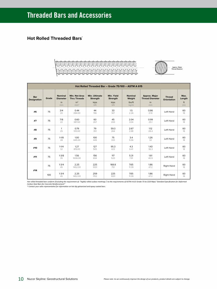
Hot Rolled Threaded Bars†
Approx. Major Thread Diameter
Hot Rolled Threaded Bar – Grade 75/100 – ASTM A 615
Bar Designation
GradeNominal Diameter
inmm
Min. Net Area Thru Threads
in2
mm2
Min. Ultimate Strength
kipskN
Min. Yield Strength
kipskN
Nominal Weight
lbs/ftkg/m
Approx. Major Thread Diameter
inmm
Thread Orientation
Max. Length
ft(m)
#6 753/420
0.44284.00
44196
33147
1.52.24
0.8621.8
Left Hand6018
#7 757/822
0.60387.00
60267
45200
2.043.04
0.9925.1
Left Hand6018
#8 751
250.79
510.0079351
59.3264
2.673.98
1.1228.4
Left Hand6018
#9 751-1/828
1.00645.00
100449
75333
3.45.06
1.2632
Left Hand6018
#10 751-1/432
1.27819.00
127565
95.3423
4.36.41
1.4336.3
Left Hand6018
#11 751-3/8
351.56
1006.00156694
117520
5.317.91
1.6140.9
Left Hand6018
#14
751-3/4
452.25
1452.002251001
168.8751
7.6511.39
1.8647.2
Right Hand6018
1001-3/4
452.25
1452.002591152
2251001
7.6511.39
1.8647.2
Right Hand6018
Hot rolled threaded bars conform (Excluding the requirement of: “legibly rolled surface markings.”) to the requirements of ASTM A 615 Grade 75 ksi (520 Mpa) “Standard Specification for Deformed Carbon Steel Bars for Concrete Reinforcement” † Contact your sales representative for information on hot dip galvanized and epoxy coated bars.

Nucor Skyline: Geostructural Solutions 11Please note: As we continuously improve the design of our products, product details are subject to change.
Threaded Bars and Accessories
Hot Rolled Threaded Bar Accessories
* Dimension of nuts and couplers are for standard thread sizes. Contact your local Nucor Skyline representative for coated or galvanized bars values.
Couplers
Grade 75 – ASTM A 576, A 108
Bar Designation
Nominal Diameter
inmm
OD
inmm
L
inmm
Weight
lbskg
#63/420
1.2531.75
3.12579.37
0.620.28
#77/822
1.5038.10
3.7595.25
0.930.42
#81
251.62541.27
4.00101.60
1.370.62
#91 1/828
1.87547.62
5.00127.00
2.311.05
#101 1/432
2.0050.80
5.75146.05
2.771.26
#111 3/835
2.2557.15
6.40162.56
3.791.72
#141 3/445
2.8873.15
7.85192.53
5.492.49
Hex Nuts (Full Load and Jam Nuts)
Grade 75 – ASTM A 576, A 108
Bar Designation
Nominal Diameter
inmm
A
inmm
B
inmm
C
inmm
Weight
lbskg
Full Jam
#63/420
1.12528.57
1.4536.83
0.8722.10
0.260.12
0.160.07
#77/822
1.37534.92
1.7544.45
0.8722.10
0.430.20
0.210.10
#81
251.5038.10
2.5063.50
0.8722.10
0.560.25
0.260.12
#91 1/828
1.7544.45
2.2557.15
0.8722.10
0.970.43
0.370.17
#101 1/432
2.0050.80
2.5063.50
1.0025.40
1.430.65
0.560.25
#111 3/835
2.2557.15
2.7569.85
1.0025.40
1.520.69
0.530.24
#141 3/445
2.5063.50
3.6091.44
1.0025.40
3.021.37
0.820.37
OD L
Jam NutHex Nut
A AB C
Hardened Washers
Grade 75 – ASTM F 436
Bar Designation
Nominal Diameter
inmm
A
inmm
B
inmm
C
inmm
Weight
lbskg
#63/420
1.7544.45
0.93823.83
.1363.45
0.070.03
#77/822
2.0050.80
1.06327.00
.1363.45
0.090.04
#81
252.2557.15
1.18830.18
.1363.45
0.110.05
#91 1/828
2.5063.50
1.37534.92
.1363.45
0.130.06
#101 1/432
2.7569.85
1.53138.89
.1363.45
0.160.07
#111 3/835
3.0076.20
1.62541.27
.1363.45
0.190.09
#141 3/445
3.2582.55
1.7744.96
.1784.52
0.300.14
AB C
Beveled Washers
Grade 75 – F 436, A536 80-55-06
Bar Designation
Nominal Diameter
inmm
A
inmm
B
inmm
C
inmm
D
inmm
Bevel
degreesWeight
lbskg
#63/420
1.7544.45
.9524.13
.7819.81
.328.13
15.320.15
#77/822
1.7544.45
1.1428.96
.7819.81
.328.13
15.370.17
#81
251.75
44.451.14
28.96.78
19.81.235.84
15.370.17
#91 1/828
2.6366.80
1.3831.75
.9323.62
.235.84
15.64
0.29
#101 1/432
2.7569.85
1.6341.40
.9724.64
.235.84
15.660.30
#111 3/835
3.0978.49
1.7544.45
1.0626.92
.235.84
15.930.45
#141 3/445
4.0010.16
2.1354.10
1.2932.77
.235.84
151.940.88
D
CA
A
BB
A

12 Nucor Skyline: Geostructural Solutions Please note: As we continuously improve the design of our products, product details are subject to change.
Commercial Grade Hollow Bar
Hollow Bar and Accessories
“R” Threaded Hollow Bar
Bar Designation
Nominal Outer Diameter
inmm
Average Inner Diameter
inmm
Effective Outer Diameter
inmm
Cross Sectional Area
in2
mm2
Ultimate Load
kipskN
Yield Load
kipskN
Approx. Major Thread Diameter
inmm
Nominal Weight
lbs/ftkg/m
R32S1.26 32
0.63 16
1.15 29.1
0.76 488
81 360
62 275
1.38 35
2.700 4.00
R38Nx19mm ID1.50 38
0.75 19
1.41 35.7
1.11 717
112 498
86 382
1.62 41
3.415 5.08
R51N2.01 51
1.30 33
1.88 47.8
1.46 939
177 787
141 627
2.13 54
5.700 8.50
“T” Threaded Hollow Bar Systems
Bar Designation
Nominal Outer Diameter
inmm
Average Inner Diameter
inmm
Cross Sectional Area
in2
mm2
Ultimate Load
kipskN
Yield Load
kipskN
Approx. Major Thread Diameter
inmm
Nominal Weight
lbs/ftkg/m
T30/111.18 30
0.43 11
0.64 413
72.0 320
58.5 260
1.30 33
2.2 3.3
T40/201.57 40
0.79 20
1.13 726
121.4 540
95.6 425
1.70 43.2
3.8 5.6
T40/161.57 40
0.63 16
1.40 903
148.4 660
118.1 525
1.70 43.2
4.8 7.2
T52/262.0552
1.0326
1.941251
208.0925
170.0756
2.2055.9
6.79.9
T76N3.00 76
2.0051
3.35 2161
319.0 1418
252.0 1120
3.20 81.3
10.2 15.2
T76S3.00 76
1.77 45
4.03 2600
418.0 1859
330.0 1467
3.20 81.3
13.2 19.7
T103/784.06 103
3.00 78
4.87 3142
510.5 2270
404.8 1800
4.20 106.7
17.0 25.3
T103/514.06 103
2.00 51
8.80 5677
823.0 3660
600.4 2670
4.20 106.7
30.0 44.6
Nominal Outer Diameter
Nominal Outer Diameter
Average Inner Diameter
Average Inner Diameter

Nucor Skyline: Geostructural Solutions 13Please note: As we continuously improve the design of our products, product details are subject to change.
Hollow Bar and Accessories
Commercial Grade Hollow Bar Accessories
Couplers
“T” Threaded Hollow Bar Couplers
Bar Designation OD
inmm
L
inmm
Weight
lbskg
T30/111.538
4.2105
1.00.45
T40/202.153
5.5140
2.61.18
T40/162.153
5.5140
2.61.18
T52/262.7
68.56.25160
5.22.36
T76N3.897
8.0200
10.24.54
T76S3.897
8.7220
14.46.53
T1035.2132
11.5292
30.513.8
“R” Threaded Hollow Bar Couplers
Bar Designation OD
inmm
L
inmm
Weight
lbskg
R32S1.743
7.5190
2.00.91
R38Nx19mm 2.564
8.7220
3.81.72
R51N2.564
8.0200
4.21.91
Centralizers
Hollow Bar Centralizers
Size OD
inmm
L
inmm
Weight
lbskg
T30
2.7570
1.4035
0.50.21
3.4088
1.4035
0.60.27
T403.4088
1.5040
0.80.37
T524.40112
1.4035
1.00.41
T765.00130
1.7545
2.00.89
T1036.40165
3.2080
6.52.94
Hex Nuts
“T” Threaded Hollow Bar Hex Nuts
Bar Designation A
inmm
B
inmm
Weight
lbskg
T30/111.8
46.01.4
36.01.0
0.45
T40/202.564.0
2.050.0
2.71.22
T40/162.564.0
2.050.0
2.61.18
T52/263.281
2.563.5
5.12.31
T76N4.0
102.03.1
80.06.22.81
T76S4.0
102.03.1
80.06.22.81
T1035.25133.0
5.125130
13.05.90
“R” Threaded Hollow Bar Hex Nuts
Bar Designation A
inmm
B
inmm
Weight
lbskg
R32S1.8
46.03.0
65.02.00.91
R38Nx19mm 2.051.0
2.060.0
1.30.59
R51N3.076.0
3.070.0
3.51.59
Size LOD
Jam NutHex Nut
A AB C

14 Nucor Skyline: Geostructural Solutions Please note: As we continuously improve the design of our products, product details are subject to change.
Hollow Bar and Accessories
* Meets “Buy America” requirements.
Domestic Hollow Bar and Accessories
“T” Threaded Hollow Bar Systems*
Bar Designation
Nominal Outer Diameter
inmm
Average Inner Diameter
inmm
Cross Sectional Area
in2
(mm2)
Minimum Ultimate Load
kipskN
Minimum Yield Load
kipskN
Approx. Major Thread Diameter
inmm
Nominal Weight
lbs/ftkg/m
T40/161.5740
0.6316
1.36879
148660
118525
1.62541.3
4.97.3
T40/201.57 40
0.79 20
1.13 726
127565
95.6 425
1.7043.2
4.46.5
T52/262.0552
1.0326
2.071337
2271009
179796
2.12554.0
6.810.1
T76/513.00 76
2.0151
3.20 2065
319 1418
252 1120
3.000 76.2
11.1 16.5
T76/453.00 76
1.77 45
3.90 2516
418 1859
330 1467
3.000 76.2
13.2 19.7
Nominal Outer Diameter
Average Inner Diameter
Couplers
“T” Threaded Hollow Bar Couplers*
Bar Designation
OD
inmm
L
inmm
Weight
lbskg
HBC PL 402.50063.5
5.50139.7
5.102.31
HBC PL 523.125
79.3756.00152.4
11.395.17
HBC PL 7603.75
95.257.875
200.0334.8115.79
Anchor Hex Nuts
“T” Threaded Hollow Bar Anchor Hex Nuts*
Bar Designation
A
inmm
L
inmm
Weight
lbskg
HBHN 402.5063.5
2.050.8
5.872.66
HBHN 523.3585.09
3.076.2
10.044.55
HBHN 7604.00101.6
3.178.7
23.8110.80
LOD
A A
L
* Meets “Buy America” requirements.

Nucor Skyline: Geostructural Solutions 15Please note: As we continuously improve the design of our products, product details are subject to change.
Hollow Bar and Accessories
Hollow Bar Bits
Drill Bit Adaptors
Adaptors
Weight
lbs/unit(kg/unit)
R32 x R380.200.09
R38 x R510.300.13
T30 x T400.300.13
Call for job specific quotes. Price depends on quantities.
Carbide Cross, Steel Cross Cut , and Button Bits
Bar SizesSize
inmm
Weight
lbs/unit(kg/unit)
T30 2.050.8
1.00.45
2.563.5
2.00.91
3.076.2
2.91.32
T40 2.563.5
2.00.91
3.076.2
2.91.32
3.588.9
3.51.59
4.0101.6
5.52.49
4.5114.3
7.03.18
5.0127.0
10.54.76
6.0152.4
13.05.90
T52 4.5114.3
7.03.18
5.0127.0
10.54.76
6.0152.4
13.05.90
T76 5.0127.0
10.54.76
6.0152.4
13.05.90
7.0177.8
14.56.58
8.0203.2
16.07.26
R32 2.050.8
1.00.45
2.563.5
2.00.91
3.076.2
2.91.32
R38 3.076.2
2.91.32
3.588.9
3.51.59
R51 4.0101.6
5.52.49
4.5114.3
7.03.18
5.0127.0
10.54.76
6.0152.4
13.05.90
All bits subject to availability. Call for stock quantities. Specialty bits available upon request.

16 Nucor Skyline: Geostructural Solutions
Hollow Bars
Hollow bars are fully threaded, “disposable” drill rods capable of drilling holes utilizing sacrificial bits that will advance the drill string to the required depth and then allow them to be grouted in place. This process creates the steel reinforcing portion of an anchor or pile. Hollow bar products are a valuable and multi-functional addition to the geotechnical contractor’s toolbox. They can be used as tie back or tie down anchors, rock anchors, soil nails and micropiles in a large array of challenging applications.
There are three basic types of drill bits for use with hollow bars: versatile cross cut bits in carbide or hardened steel, button bits for intact rock in carbide or hardened steel and steel stepped clay bits for cohesive soils. The selection of the drill bit type and size is based on the material that is being drilled through and the desired borehole diameter. A larger borehole diameter provides greater load carrying capacity and greater grout cover. Grout cover protects the anchor rod from corroding. Depending on the actual soil type, a 2.5 inch diameter bit can produce a 6 to 8 inch diameter grout column.
Production rates are increased through the use of hollow bar systems, as compared to traditional solid bar anchors. This is especially true when drilling through difficult conditions. In sites with low headroom, large scale drilling rigs and hole casing systems can be avoided. With drill rigs where “through the head grouting” is not available, grout swivels can be used to retrofit standard rotary percussion drills.
Hollow Bar Corrosion Protection
The level of corrosion protection is dependent on the anticipated service life of the anchor, installation methods, and the corrosion potential (aggressiveness) of the environment. The FHWA has studied the effects of installation on both galvanized and epoxy coated bars as reported in FHWA CFL/TD10-002. This study revealed epoxy coatings were both partially and completely removed at the leading edge of the screw profile and around the couplings.
The installations were constructed using hollow bars as both the drill rod and reinforcement. The effects of the removal reduced the service life of the bar substantially by creating concentrated locations for potential corrosion. As such, the designer should evaluate all possibilities when determining the level of corrosion protection required.
Hot Dipped Galvanizing
Hot dipped galvanizing is a form of galvanization and is the process of coating a base metal such as steel with molten zinc. The zinc acts as a sacrificial material to the steel. The galvanized coating is manufactured in accordance with ASTM A 53 standards and is more resistant to handling than epoxy coatings.
Sacrificial Steel
Using sacrificial steel as a form of corrosion protection requires a geotechnical evaluation of the corrosivity of the soils. The estimated loss of steel thickness is calculated and then the hollow bar is designed with the additional increase in thickness.
Product Detail: Hollow Bar Systems

Nucor Skyline: Geostructural Solutions 17Please note: As we continuously improve the design of our products, product details are subject to change.
Product Detail: Hollow Bar Systems
Loss of Thickness Due to Corrosion for Piles in Soil with or without Groundwater
Required design working life5 Years 25 Years 50 Years 75 Years 100 Years
in / mm
Undisturbed natural soils (sand, clay, schist, …) 0.0000.00
0.0120.30
0.0240.60
0.0350.90
0.0471.20
Polluted natural soils and industrial grounds 0.0060.15
0.0300.75
0.0591.50
0.0892.25
0.1183.00
Aggressive natural soils (swamp, marsh, peat, …) 0.0080.20
0.0391.00
0.0691.75
0.0982.50
0.1283.25
Non-compacted and non-aggressive fills (clay, schist, sand, silt, …)
0.0070.18
0.0280.70
0.0471.20
0.0671.70
0.0872.20
Non-compacted and aggressive fills (ashes, slag, …) 0.0200.50
0.0792.00
0.1283.25
0.1774.50
0.2265.75
Notes:
1. Corrosion rates in compacted fills are lower than those in non-compacted ones. In compacted fills, the figures in the table should
be divided by two.
2. The values given are only for guidance. Local conditions should be considered because they may affect the actual corrosion rate,
which can be lower or higher than the average value given in the table.
3. The values given for 5 and 25 years are based on measurements, whereas the other values are extrapolated.
Loss of Thickness Due to Corrosion for Piles in Fresh Water or in Sea Water
Required design working life5 Years 25 Years 50 Years 75 Years 100 Years
in / mm
Common fresh water (river, ship canal, …) in the zone of high attack (water line)
0.0060.15
0.0220.55
0.0350.90
0.0451.15
0.0551.40
Very polluted fresh water (sewage, industrial effluent, …) in the zone of high attack (water line)
0.0120.30
0.0511.30
0.0912.30
0.1303.30
0.1694.30
Sea water in temperate climate in the zone of high attack (low water and splash zones)
0.0220.55
0.0741.90
0.1483.75
0.2205.60
0.2957.50
Sea water in temperate climate in the zone of permanent immersion or in the intertidal zone
0.0100.25
0.0350.90
0.0691.75
0.1022.60
0.1383.50
Notes:
1. The highest corrosion rate is usually found at the splash zone or at the low water level in tidal waters. However, in most cases, the
highest stresses are in the permanent immersion zone.
2. The values given are only for guidance. Local conditions should be considered because they may affect the actual corrosion rate,
which can be lower or higher than the average value given in the table.
3. The values given for 5 and 25 years are based on measurements, whereas the other values are extrapolated.
Steel Thickness Reduction Values Due to Corrosion
18 Nucor Skyline: Geostructural Solutions Please note: As we continuously improve the design of our products, product details are subject to change.
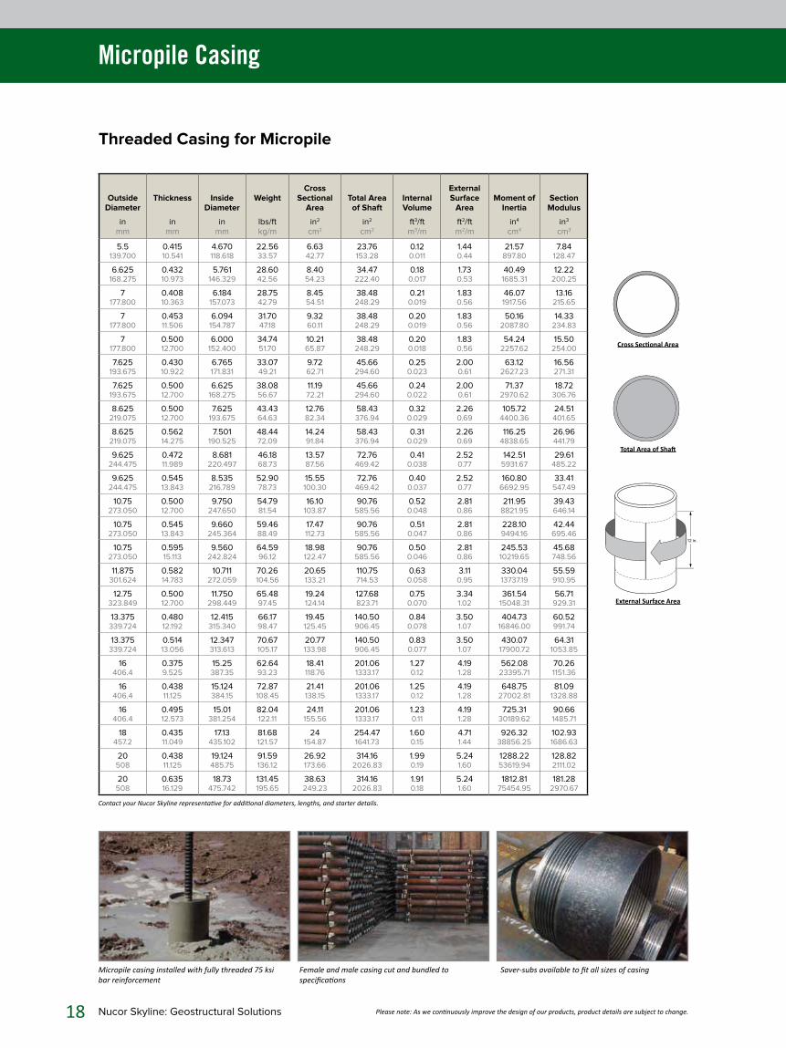
Micropile Casing
External Surface Area
Total Area of Shaft
Cross Sectional Area
Threaded Casing for Micropile
Outside Diameter
inmm
Thickness
inmm
Inside Diameter
inmm
Weight
lbs/ftkg/m
Cross Sectional
Area
in2
cm2
Total Area of Shaft
in2
cm2
Internal Volume
ft3/ftm3/m
External Surface
Area
ft2/ftm2/m
Moment of Inertia
in4
cm4
Section Modulus
in3
cm3
5.5139.700
0.41510.541
4.670118.618
22.5633.57
6.6342.77
23.76153.28
0.120.011
1.440.44
21.57897.80
7.84128.47
6.625168.275
0.43210.973
5.761146.329
28.6042.56
8.4054.23
34.47222.40
0.180.017
1.730.53
40.491685.31
12.22200.25
7177.800
0.40810.363
6.184157.073
28.7542.79
8.4554.51
38.48248.29
0.210.019
1.830.56
46.071917.56
13.16215.65
7177.800
0.45311.506
6.094154.787
31.7047.18
9.3260.11
38.48248.29
0.200.019
1.830.56
50.162087.80
14.33234.83
7177.800
0.50012.700
6.000152.400
34.7451.70
10.2165.87
38.48248.29
0.200.018
1.830.56
54.242257.62
15.50254.00
7.625193.675
0.43010.922
6.765171.831
33.0749.21
9.7262.71
45.66294.60
0.250.023
2.000.61
63.122627.23
16.56271.31
7.625193.675
0.50012.700
6.625168.275
38.0856.67
11.1972.21
45.66294.60
0.240.022
2.000.61
71.372970.62
18.72306.76
8.625219.075
0.50012.700
7.625193.675
43.4364.63
12.7682.34
58.43376.94
0.320.029
2.260.69
105.724400.36
24.51401.65
8.625219.075
0.56214.275
7.501190.525
48.4472.09
14.2491.84
58.43376.94
0.310.029
2.260.69
116.254838.65
26.96441.79
9.625244.475
0.47211.989
8.681220.497
46.1868.73
13.5787.56
72.76469.42
0.410.038
2.520.77
142.515931.67
29.61485.22
9.625244.475
0.54513.843
8.535216.789
52.9078.73
15.55100.30
72.76469.42
0.400.037
2.520.77
160.806692.95
33.41547.49
10.75273.050
0.50012.700
9.750247.650
54.7981.54
16.10103.87
90.76585.56
0.520.048
2.810.86
211.958821.95
39.43646.14
10.75273.050
0.54513.843
9.660245.364
59.4688.49
17.47112.73
90.76585.56
0.510.047
2.810.86
228.109494.16
42.44695.46
10.75273.050
0.59515.113
9.560242.824
64.5996.12
18.98122.47
90.76585.56
0.500.046
2.810.86
245.5310219.65
45.68748.56
11.875301.624
0.58214.783
10.711272.059
70.26104.56
20.65133.21
110.75714.53
0.630.058
3.110.95
330.0413737.19
55.59910.95
12.75323.849
0.50012.700
11.750298.449
65.4897.45
19.24124.14
127.68823.71
0.750.070
3.341.02
361.5415048.31
56.71929.31
13.375339.724
0.48012.192
12.415315.340
66.1798.47
19.45125.45
140.50906.45
0.840.078
3.501.07
404.7316846.00
60.52991.74
13.375339.724
0.51413.056
12.347313.613
70.67105.17
20.77133.98
140.50906.45
0.830.077
3.501.07
430.0717900.72
64.311053.85
16406.4
0.3759.525
15.25387.35
62.6493.23
18.41118.76
201.061333.17
1.270.12
4.191.28
562.0823395.71
70.261151.36
16406.4
0.43811.125
15.124384.15
72.87108.45
21.41138.15
201.061333.17
1.250.12
4.191.28
648.7527002.81
81.091328.88
16406.4
0.49512.573
15.01381.254
82.04122.11
24.11155.56
201.061333.17
1.230.11
4.191.28
725.3130189.62
90.661485.71
18457.2
0.43511.049
17.13435.102
81.68121.57
24154.87
254.471641.73
1.600.15
4.711.44
926.3238856.25
102.931686.63
20508
0.43811.125
19.124485.75
91.59136.12
26.92173.66
314.162026.83
1.990.19
5.241.60
1288.2253619.94
128.822111.02
20508
0.63516.129
18.73475.742
131.45195.65
38.63249.23
314.162026.83
1.910.18
5.241.60
1812.8175454.95
181.282970.67
Contact your Nucor Skyline representative for additional diameters, lengths, and starter details.
Saver-subs available to fit all sizes of casingFemale and male casing cut and bundled to specifications
Micropile casing installed with fully threaded 75 ksi bar reinforcement

Nucor Skyline: Geostructural Solutions 19Please note: As we continuously improve the design of our products, product details are subject to change.
Micropile Casing
Casing accessories include duplex and flange adapters API drill rods and casing subs are typical tooling itemsDownhole hammers and bits are available in various sizes and shank configurations
Micropile Casing Accessories
Nucor Skyline is positioned to deliver complete accessory packages with your threaded casing. We understand the urgency of your project and stock a wide range of micropile casing accessories for immediate delivery.
J-Teeth Grout Heads Duplex Adapters
Ring Bits Shear Rings Flange Adapters
Casing Shoes Protective Caps Casing Crossover Subs
Tooling Items
Custom machining is available for duplex and flange adapters to match casing, drill, and drill system requirements. We can also fabricate crossover subs to fit any existing tooling items.
Nucor Skyline offers the following tooling items for the installation of micropile casing:
Air Swivels API Crossover Subs API Drill Rods (2 3/8 in to 6 5/8 in)
Breakout Wrenches Casing Crowns Cushion Subs
Diverter Heads Downhole Hammers Downhole Hammer Bits
Drag Bits Floating Subs Flushing Heads
Grout Swivels Ictology Bits Stabilizers
Tricone Bits
20 Nucor Skyline: Geostructural Solutions Please note: As we continuously improve the design of our products, product details are subject to change.
Multi-Strand Anchor Systems
Multi-Strand Anchor Systems
STEEL ANCHORHEADCAP (OPTIONAL)
AØ
GR50 OR A36BEARING PLATE**
A500STEEL TRUMPET PIPE
H
16”
Typ.
AASHTO M252HDPE CORRUGATEDSHEATH
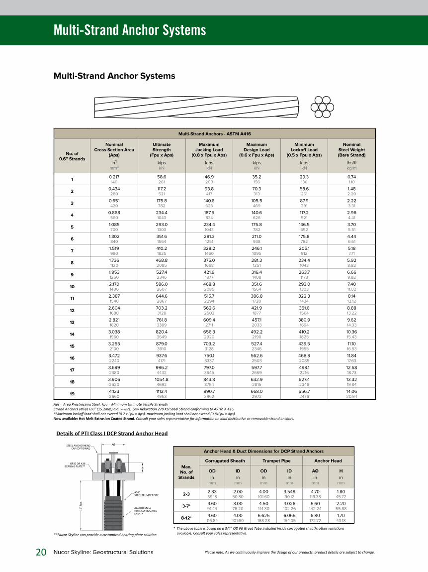
Anchor Head & Duct Dimensions for DCP Strand Anchors
Max. No. of
Strands
Corrugated Sheath Trumpet Pipe Anchor Head
OD
inmm
ID
inmm
OD
inmm
ID
inmm
AØ
inmm
H
inmm
2-32.3359.18
2.0050.80
4.00101.60
3.54890.12
4.70119.38
1.8045.72
3-7*3.6091.44
3.0076.20
4.50114.30
4.026102.26
5.60142.24
2.2055.88
8-12*4.60
116.844.00
101.606.625168.28
6.065154.05
6.80172.72
1.7043.18
* The above table is based on a 3/4” OD PE Grout Tube installed inside corrugated sheath, other variations available. Consult your sales representative.**Nucor Skyline can provide a customized bearing plate solution.
Details of PTI Class I DCP Strand Anchor Head
Multi-Strand Anchors - ASTM A416
No. of 0.6” Strands
Nominal Cross Section Area
(Aps)
in²mm²
Ultimate Strength
(Fpu x Aps)
kipskN
Maximum Jacking Load
(0.8 x Fpu x Aps)
kipskN
Maximum Design Load
(0.6 x Fpu x Aps)
kipskN
Minimum Lockoff Load
(0.5 x Fpu x Aps)
kipskN
Nominal Steel Weight (Bare Strand)
lbs/ftkg/m
10.217140
58.6261
46.9209
35.2156
29.3130
0.741.10
20.434280
117.2521
93.8417
70.3313
58.6261
1.482.20
30.651420
175.8782
140.6626
105.5469
87.9391
2.223.31
40.868560
234.41043
187.5834
140.6626
117.2521
2.964.41
51.085700
293.01303
234.41043
175.8782
146.5652
3.705.51
61.302840
351.61564
281.31251
211.0938
175.8782
4.446.61
71.519980
410.21825
328.21460
246.11095
205.1912
5.187.71
81.7361120
468.82085
375.01668
281.31251
234.41043
5.928.82
91.9531260
527.42346
421.91877
316.41408
263.71173
6.669.92
102.1701400
586.02607
468.82085
351.61564
293.01303
7.4011.02
112.3871540
644.62867
515.72294
386.81720
322.31434
8.1412.12
122.6041680
703.23128
562.62503
421.91877
351.61564
8.8813.22
132.8211820
761.83389
609.42711
457.12033
380.91694
9.6214.33
143.0381960
820.43649
656.32920
492.22190
410.21825
10.3615.43
153.2552100
879.03910
703.23128
527.42346
439.51955
11.1016.53
163.4722240
937.64171
750.13337
562.62503
468.82085
11.8417.63
173.6892380
996.24432
797.03545
597.72659
498.12216
12.5818.73
183.9062520
1054.84692
843.83754
632.92815
527.42346
13.3219.84
194.1232660
1113.44953
890.73962
668.02972
556.72476
14.0620.94
Aps = Area Prestressing Steel, Fpu = Minimum Ultimate Tensile StrengthStrand Anchors utilize 0.6” (15.2mm) dia. 7-wire, Low Relaxation 270 KSI Steel Strand conforming to ASTM A 416.*Maximum lockoff load shall not exceed (0.7 x Fpu x Aps), maximum jacking load shall not exceed (0.8xFpu x Aps)Now available: Hot Melt Extrusion Coated Strand. Consult your sales representative for information on load distributive or removable strand anchors.

Nucor Skyline: Geostructural Solutions 21Please note: As we continuously improve the design of our products, product details are subject to change.
Product Detail: Multi-Strand Anchors
Multi-Strand Ground Anchors
As a result of recent technological developments in the structural post-tensioning industry, the production of ground anchors with a very high capacity is possible. The use of strand anchors in rock and soil anchor applications has become a well respected tool in the geotechnical engineer’s arsenal of solutions. By utilizing the combined load carrying capacity of multiple 0.6 inch diameter prestressing steel strands, loads which greatly exceed the tensile strength of any single bar can be achieved.
Strand anchors can be produced in extremely long lengths. For instance, strand anchors measuring anywhere from 100 to 200 feet in length can be assembled, coiled and banded in one of our manufacturing locations and shipped on wooden pallets via conventional flat-bed trucks.
In addition, many of the strand anchors used in temporary excavation support consist of seven strands or less. These anchors can often be uncoiled and installed by hand. Strand anchors also generally require much less site storage space and handling than bar anchors. We offer customized strand anchor manufacturing which allows for the design to be optimized in terms of both load carrying capacity and geometry to meet the requirements of specific site conditions. Nucor Skyline is committed to bringing the latest developments in global strand anchoring technology to the North American geotechnical construction industry. Innovations such as load distributive and removable strand anchors are available from Nucor Skyline. A key element in being able to use these technologies is having the practical installation equipment to test and lock off these types of anchors.
Multi-strand anchors having individual strands of different lengths can pose many challenges when using traditional hollow ram jacks. Our partnership with Samwoo allows us to offer a unique multi-ram manifold jack system that is capable of maintaining an equal load in each strand, independent of the elongation.
Load Distributive Multi-Strand Anchors
Over the years, the geotechnical industry has benefited from improvements in the cost and performance of traditional North American bundled multi-strand anchors. Over 20 years ago, the “Single Bore Multiple Anchor (SBMA)” concept, also known as “Load Distributive Tensile Anchor (LDTA)” was developed. Load Distributive Compression Anchors (LDCA) were introduced shortly thereafter. Nucor Skyline offers both tensile and compression load distributive strand anchor systems.

22 Nucor Skyline: Geostructural Solutions
Product Detail: Multi-Strand Anchors
Relative Bond Stress Distribution
Tension Anchor (North American Standard)
As described in the Post- Tensioning Institute’s publication “Recommendations of Rock and Soil Anchors,” bond stresses are not uniform over the tendon bond length. When a tension load is applied to this type of anchor, load transfer to the bond length is developed through adhesion of the borehole grout to the steel strand. Theoretical and experimental analysis shows that the bond stress concentration at the top of the bond zone is fairly uniform at low loads. As the load increases, de-bonding of the strand/grout occurs and the peak bond stress moves down the bond length.
In strain sensitive soils, the residual bond stress could be significantly less than the ultimate bond stress. To overcome this effect, designers sometimes extend the unbonded length of the anchor to a specific depth to attempt to load some of the bond length in compression.
Compression Anchors
Compression type anchors typically have a structure, such as a plate, which transfers load to the bond length at the distal end of the tendon. The compression type anchor has the advantage of exerting load to the grout as a compressive force. This type of anchor requires a high-strength grout. In addition, a similar bond stress transfer mechanism to the ground still occurs, but it takes place in the reverse direction.
Load Distributive Compression Anchors (LDCA)
A sensible method to overcome the limitations of the peak stress transfer effect to the ground is to more equally distribute the stress over the entire bond length. Load distributive compression (LDCA) type anchors, such as those offered by the Samwoo system, apply load to multiple points by using “anchor bodies” as a point of load transfer. Sheathed strands end in each of the anchor bodies within the anchor tendon. To optimize the entire length of the bond zone, the designer has the ability to specify the spacing or location of the anchor bodies, resulting in a much more equal distribution of peak bond stress.
The Smart Anchor, the most recent tensile type load distributive anchor offering by Samwoo is capable of securing stable loads in even relatively weak soils such as clay and silts. This anchor has an anchor body with a bare strand tail behind it which greatly increases the bond stress distribution at each anchor point.
LDCAs minimize creep and maximize the holding power of a multi-strand ground anchor.
Load Change Diagram (Fig. 1)
Load Distribution Graph (Fig. A) Load Distribution Graph (Fig. B) Load Distribution Graph (Fig. C)
Load Change Diagram (Fig. 2)
Load Change Diagram (Fig. 3-1)
Load Change Diagram (Fig. 3-2)

Nucor Skyline: Geostructural Solutions 23
Product Detail: Multi-Strand Anchors
HDPE Extruded Steel Strand w/Corrosion Inhibiting Grease
Steel Strand
Compression GripSpacer
Block
Anchor Body
Max Bracket(Angle Free Bracket)
AnchorHead
Borehole Grout
Borehole
Bond Length
Free Le
ngth
Bond Length (N
2)
Bond Length (N
1)
The Load Distributive Tension Anchors (LDTA), or Smart Anchors, are load distributive tension type removable anchors designed to uniformly transfer skin friction to the grout body and soil. This is done throughout the entire bond length, rather than applying a concentrated force at the distal end of the anchor body. These anchors were developed for the purpose of securing anchorage forces in relatively weak soils with N values less than 10. The removal process for a smart anchor is similar to that used with Removable Load Distributive Compression Anchors (LDCA-Removable).
Features
• The load distributive design allows the anchoring force to be secured in soils with low confining pressure (approx. N ≤ 10).
• Minimizes the working space required for strand removal.
• Removal cost is minimized by ease of strand removal in difficult soils.
• When applied to weak ground, constructability, convenience and economic efficiency are outstanding, especially when compared to other techniques.
• Acceptable anchor performance is possible with a lower strength grout than is required for LDCAs.
Load Distributive Tension Anchors (LDTA) – Smart Anchors
CLASS I CORROSION PROTECTION – (DCP)
CLASS II CORROSION PROTECTION – (SCP)
Greased and Sheathed Portions
Greased and Sheathed Portions
Bond Portions
Bond Portions
Load Distributive Tension Anchors

24 Nucor Skyline: Geostructural Solutions
Product Detail: Multi-Strand Anchors
HDPE Extruded Steel Strand w/Corrosion Inhibiting Grease
HDPE Extruded Steel Strand w/Corrosion Inhibiting Grease
Single Anchor Body
ConcreteBlock
ProtectionCap
AnchorHead
Borehole GroutBorehole
Double Anchor Body
Borehole Grout
Borehole
Bond Length
Free Le
ngth
Bond Length
Free Le
ngth
ConcreteBlock
Permanent Load Distributive Compression Anchors (LDCA-Permanent)
The permanent Load Distributive Compression Anchors (LDCA-Permanent) are intended to function for a period of time exceeding two years, as recommended by the Post-Tensioning Institute (PTI) manual. These anchors utilize a pre-stressing steel strand that is greased and sheathed for outstanding corrosion resistance. The strand passes through the anchor body where it is held by a set of wedges. The wedges, set at the back side of the anchor body, are permanently factory set and do not have the ability to be released from the anchor head.
The positioning of the wedges allows the jacking force to be distributed along the length of the anchor body. This maximizes the effectiveness of the cross-sectional area of the grout column in the borehole. In addition to being used in numerous applications, these anchors are mainly used for: permanent sheathing and shoring solutions, resisting buoyancy forces in tie down anchors, slope stabilization and landslide control.
Features
• The aluminum anchor body and corrosion resistant housing provides a powerful corrosion resistant system.
• The number of steel strands is easily adjusted according to the design loads and soil conditions.
• Anchors are manufactured in a standardized, semi-automated facility with advanced equipment, resulting in stringent quality control and outstanding quality assurance.
• Anchors are fully assembled, coiled and stacked on pallets, making them ideal for transportation, job site use and long-term storage.
Upgraded• The newly developed corrosion-resistant aluminum die-casting anchor body• Further improved part precision and bonding method• Superb steel strand protection structure and grout infiltration blocking effect

Nucor Skyline: Geostructural Solutions 25
The Removable Load Distributive Compression Anchors (LDCA-Removable) are load distributive anchors that offer a complete solution where the removal of the anchorage system is required upon becoming redundant. Often times, municipalities and similar organizations will not approve obstructions that are left in the ground after a project is completed for fear that they will conflict with upcoming developments or may require third-party approval in the future. These types of compression anchors offer a cost-effective solution where conventional tie back anchors are not approved. Otherwise, the only alternative for a contractor is a internally braced system with rakers or struts.
The pre-stressing steel strand, in its entirety, can be easily and quickly removed by hand. This can be accomplished by rotating the strand that disengages the wedges at the back end of the anchor body and then withdrawing the steel strand through the HDPE sheath. All that is left behind is the small aluminum anchor body and the plastic sheath. Since the strand passes through the anchor body where it is held by a set of wedges, the jacking force is distributed along the length of the anchor body. This maximizes the effectiveness of the cross-sectional area of the grout column in the borehole. Since their inception, LDCA anchors have been utilized in numerous projects around the world to provide lateral support to temporary sheathing and shoring solutions.
Features
• The tensile force is distributed evenly along the bond length making it ideal for highly plastic clay soils.
• The diameter of a 2-strand anchor body is 4.5”, for a 0.6” diameter steel strand. Therefore, the anchor body can easily be installed in a 5.5” or larger borehole.
• Additional corrosion protection is provided by the continuous heavy wall HDPE sheath.
• The steel strand can be easily removed or re-engaged to the body by rotating the strand with a pair of pliers; resulting in minimized site access and removal process.
• Having strands individually secured to the distal end of the anchor body, maximizes design performance and reduces eccentricity.
• Up to 4,000 of these anchors have been used on a single project with over a 99% successful removal rate.
HDPE Sheath Steel Strand w/Corrosion Inhibiting Grease
HDPE Sheath Steel Strand w/Corrosion Inhibiting Grease
Single Anchor Body
Max Bracket(Angle Free Bracket)
AnchorHead
Borehole Grout
Borehole
Double Anchor Body
Borehole GroutBorehole
Bond Length
Free Le
ngth
Bond Length
Free Le
ngth
How to Remove
1. Cut the steel strand.
2. Separate the steel strand from the waler and remove the waler.
3. Rotate the steel strand in a clockwise direction and open the wedge.
4. Manually remove the steel strand and separate from the open wedge.
Principles of Removable Compression Anchors
Jacking and fixing Cutting wire, moving wedge
Rotating wire, opening wedge
Removing strand
Removable Load Distributive Compression Anchors (LDCA-Removable)
Upgraded• The newly developed corrosion-resistant aluminum die-casting anchor body• Further improved part precision and bonding method• Superb steel strand protection structure and grout infiltration blocking effect

26 Nucor Skyline: Geostructural Solutions
Applications: Ground Anchors
Ground Anchors
Over the past 50 years, fully threaded, high strength threaded bar and multi-strand anchor systems with corrosion protection have developed into the most accepted and highly reliable ground anchorages available. As the leading steel supplier in the United States’ foundation industry, Nucor Skyline manufactures the most extensive selection of cold and hot rolled, high strength, fully threaded bars; available in both 75 ksi and 150 ksi steel grades.
Nucor Skyline offers the most advanced multi-strand ground anchor technology available in the geotechnical industry in the United States. In addition to traditional multi-strand PTI Class I permanent and Class II temporary strand anchors, we have the world’s most convenient and widely used removable strand anchor system.
Manufactured in the United States with domestic strand, heads and wedges, we supply the required jacking systems and the technical field support to allow contractors to economically use this technology. Already proven on commercial projects in the United States, a full scale experimental and theoretical evaluation of the system has been conducted in accordance with US standards by one of the geotechnical industries’ most respected independent consulting engineering firms at a location administered by an American university. This information is available to all, along with the technical support required for use of the system.
Advantages
• Highly versatile and well proven method of transferring tension forces to the ground
• Used in a wide array of installation techniques developed to drive cost-efficient construction in the geotechnical industry
• Tie back installations eliminate internal bracing and rakers which typically congest the excavation. This dramatically increases the efficiency of material removal by the contractor during temporary excavation
• Reliable permanent anchors, with decades of proven performance, allow engineers to confidently design structural and slope stabilization projects
• Tie down applications often replace mass concrete, reducing construction costs
Waterfront
Square –
Philadelphia, PA
Applications
• Retaining Walls: Tie backs are used as either a permanent or temporary anchor system for permanent retaining walls or support of excavation.
• Resist Uplift: Used to resist hydrostatic uplift pressures on a slab, structural force, or wind loads on a structure.
• Sloped Surface Stabilization
• Landslide Mitigation
• Foundation Stabilization

Nucor Skyline: Geostructural Solutions 27
PermanentWall
PermanentTieback
Soil
TemporarySheeting
TemporarySheeting
TemporaryTieback
FutureStation
ExistingDam
PermanentTiedown
PermanentTiedown
Tower
BridgeAbutment
Tension inAnchor
Uplift
Floor Slab
SlopeProtection
Anchor
ExistingBuilding
Typical Uses for Ground Anchors
Applications: Ground Anchors

28 Nucor Skyline: Geostructural Solutions
FREE LENGTH
BOND LENGTH
TAIL
HEX NUT &FLAT WASHER
CAST IN PLACERETAINING WALL
HEX JAM NUT
HEX NUT &FLAT WASHERTHREADED BAR
BEARING PLATE
BEARING PLATE
INTERNAL PLUG
WELDED PIPE TRUMPET
TAPE SEALTAPE SEAL CEMENTITIOUS
GROUT POLY CORRUGATEDTUBING
COUPLER ASSEMBLY HEAT SHRINK
TUBINGCENTRALIZER
END CAP
DRILL HOLE
Applications: Ground Anchors
Tie Back or Tie Down Anchors
Tie backs are fully threaded steel bars that are bored, cast-in-place elements designed to resist tension forces resulting from the support of earth retention systems, such as: foundation walls or retaining walls.
Tie backs are commonly used to support temporary walls for excavations in congested urban areas. One type of temporary wall is a beam and lagging wall. The use of tie downs in this application reduces the amount of soil disturbed during excavation and decreases the disturbance on adjacent structures. In this very common application, H-piles are tremie concreted into drilled holes in a vertical orientation, along the perimeter of the intended excavation. Wood lagging is installed horizontally to retain the soil behind and between the piles as the top-down excavation takes place.
Anchor design is based on well-documented and proven principles. Once the structural loading has been identified, the geotechnical information available from the site can be used to determine the appropriate anchor design, as recommended in the PTI Manual “Recommendations of Rock and Soil Anchors”.
The design must take the variability that occurs throughout most sites into consideration. For example, the Great Lakes Region is a region where glaciers traversed the landscape, carving and filling vast areas with sand, clay, gravel and countless combinations of all soil types. Soils may contain boulders, cobbles, gravel and other obstructions which make it challenging to drill holes. As a result, soil conditions vary drastically from site to site. For example, in parts of Texas, Oklahoma and in the upper Missouri Valley, clay soils may be expansive and may dominate the design of ground anchors.
Soil borings and laboratory testing should be used to verify the actual soil conditions in the location of a proposed anchor.
Prior to starting a tie back or tie down anchor design, a licensed geotechnical engineer should be consulted. A simple, standardized design process may be applied using a prescribed method such as the following:
Geotechnical Considerations
• Soils: Cohesive, cohesionless or rock
• Design life: Permanent or temporary (less than 2 years)
• Loading type: Tensile, compressive or lateral
• N-values: Obtained from STP test
• Termination depth
• Corrosion potential
Structural Considerations
• Surface surcharge loading type: Tensile, compressive or lateral
• Groundwater
• Soil properties
• Buckling
Field Quality Control
• Site access
• Installation methods
• Load testing requirements
Typical Grouted Class I Permanent Anchor

Nucor Skyline: Geostructural Solutions 29
Applications: Ground Anchors
Corrosion Protection
Corrosion protection is a technique used to extend the design life of an anchor. It is extremely important to protect the integrity of the steel which could be significantly damaged if a method of corrosion protection is not utilized. The level of corrosion protection varies and is controlled by the aggressiveness of the environment and the desired design life. It is the responsibility of the design engineer to select an appropriate level of protection.
All bar and strand anchors can be supplied with a protective smooth-walled PVC tube. While the standard PVC tube is 0.035 inch thick, other options are available upon request.
The following corrosion protection options are available for all bars and strands:
Double Corrosion Protection (DCP)/PTI Class I
With Double Corrosion Protection, the threaded bar is typically encased in a factory grouted, PVC or HDPE corrugated plastic. DCP fabrication is used mainly for permanent applications or in uncertain and aggressive environments. For strand anchors, the strand is placed in the corrugated duct in the factory and grouted entirely in the field.
BOREHOLE GROUT
END CAP
DRILL HOLE
EXTERNAL CENTRALIZER
INTERNAL SPACERS
TRUMPET
WEDGES
ANCHOR HEAD
BEARING PLATE
UNBONDED LENGTH
BOND LENGTH
PRESTRESSING STEEL STRANDINDIVIDUALLY COVERED IN CORROSIONINHIBITING COMPOUND AND SHEATHED
FILLED WITH CORROSIONINHIBITING COMPOUND ORGROUTFILLED WITH CORROSION
INHIBITING COMPOUND ORGROUT
ANCHOR HEAD COVER(OPTIONAL)
ENCAPSULATION CORRUGATED SHEATHINGGROUT FILLED (FULL LENGTH OF ANCHOR)
CAP COVER(OPTIONAL)
FILLED WITH CORROSION INHIBITING COMPOUND OR GROUT
GROUT FILLED CORRUGATEDSHEATHING
CENTRALIZER
PRESTRESSING STEELTHREADED BAR
END CAP
TRUMPET
SEAL
BEARING PLATE
FULL LOAD NUT
FILLED WITH CORROSIONINHIBITING COMPOUND OR
GROUT
BOREHOLE GROUT
SMOOTH PVC OVERUNBONDED LENGTH
UNBONDED LENGTH
BOND LENGTH
Class I Protection: Bar Anchor (DCP)
Class I Protection: Strand Anchor (DCP)
STEEL ANCHOR HEADCAP (OPTIONAL)
AØ
GR50 OR A36BEARING PLATE**
A500STEEL TRUMPET PIPE
H
16”
Typ.
AASHTO M252HDPE CORRUGATEDSHEATH
Anchor Head & Duct Dimensions for DCP Strand Anchors
Max. No. of
Strands
Corrugated Sheath Trumpet Pipe Anchor Head
OD
inmm
ID
inmm
OD
inmm
ID
inmm
AØ
inmm
H
inmm
2-32.3359.18
2.0050.80
4.00101.60
3.54890.12
4.70119.38
1.8045.72
3-7*3.6091.44
3.0076.20
4.50114.30
4.026102.26
5.60142.24
2.2055.88
8-12*4.60
116.844.00
101.606.625168.28
6.065154.05
6.80172.72
1.7043.18
* The above table is based on a 3/4” OD PE Grout Tube installed inside corrugated sheath, other variations available. Consult your sales representative.
**Nucor Skyline can provide a customized bearing plate solution.
Details of PTI Class I DCP Strand Anchor Head

30 Nucor Skyline: Geostructural Solutions
BOREHOLE GROUT
BOND LENGTH
UNBONDED LENGTH
INTERNAL SPACERS
DRILL HOLE
EXTERNAL CENTRALIZER
WEDGES
ANCHOR HEAD
BEARING PLATE
PRESTRESSING STEEL STANDINDIVIDUALLY COVERED IN CORROSIONINHIBITING COMPOUND AND SHEATHED
• Encapsulating: Grease or Grout
• Hot Melt Fusion-bonded Epoxy Coating
• Coal Tar Epoxy Coating
• Hot Dip Galvanizing
• Multi-layer Painting
• Heat Shrink Seals
• Mastic Backed Tape Systems (i.e. DENSO™)
Oversized accessories are provided to accommodate galvanized and coated bars.
Applications: Ground Anchors
Single Corrosion Protection (SCP)/PTI Class II
In a Single Corrosion Protection (SCP) system, the bar or strand is sleeved with a HDPE or PVC plastic sheath through the free length of the anchor. SCP fabrication is used primarily for temporary applications, but can also be leveraged for non-aggressive, permanent applications.
Factory-issued corrosion protection options include:
Class II Protection: Bar Anchor (SCP)
Class II Protection: Strand Anchor (SCP)
BOREHOLE GROUT
PRESTRESSING STEELTHREADED BAR
GREASED AND SHEATHEDSMOOTH PLASTIC WITH CORROSIONINHIBITING COMPOUND
FULL LOAD NUT
BEARING PLATE
UNBONDED LENGTH
BOND LENGTH
CENTRALIZER
SEAL

Nucor Skyline: Geostructural Solutions 31
Rock Bolts and Anchor Bolts
Rock bolts support the face of a rock slope or cut. When securing the face of an excavation, rock bolts are used to support the unstable rock on the surface to the more stable rock behind the excavation. Roof bolts anchor the overhead portion of the tunnel excavation to the more stable rock above it. Anchor bolts serve to connect a structure to its foundation and can be used when securing wind turbines, tower structures, sign posts, stairways, and buildings.
Advantages
• Threaded bar rolling facilities which manufacture anchor bolts to strict tolerances
• Grade 75 and Grade 150 threaded bars show minimum relaxation under tension
• Large diameter anchor bolts can be designed to meet minimum yield strengths of up to 847 kips, with an ultimate strength of 1,059 kips or over 500 tons
WIND TOWER SHELL
THREADED BAR
HEX NUT
F-436 HARDENED WASHER
PVC BOLT SLEEVE
TEMPLATE TOP RING
TOWER FLANGE
EMBEDMENT RING
F-436 HARDENED WASHER
HEX NUT
Wind Turbine Anchor Bolt
Applications
• Wind Turbine Anchor Bolts
• Utility Tower Anchor Bolts
• Sloped Surface and Rock Face Stabilization
Berkshire
Wind Power
Project –
Hancock, MA
Applications: Rock Bolts/Anchor Bolts

32 Nucor Skyline: Geostructural Solutions
Applications: Soil Nails
Applications
• Temporary Support of Excavation
• Permanent Retaining Walls
• Slide Stabilization
Soil Nails
Soil nails are bars installed within an excavation or slope to provide reinforcement to an earth retention structure. They differ from tie backs in that they are considered passive elements and are not actively loaded in tension like a prestressed ground anchor. Soil nails are used in combination with a steel grid cover and shotcrete. As a system, the soil nail, grid cover, and shotcrete act as a coherent mass with enough strength to resist the overburden pressure of the surrounding soil mass, as well as any surcharge pressure.
In comparison to tie back anchors, soil nails have a few significant benefits. The equipment required to install soil nails is relatively small and mobile, providing a distinct advantage for applications with tight spaces or noise control issues. Using soil nails is typically a more flexible construction technique, allowing for simpler on-site modifications. Also, soil nails are installed early on in the construction process, limiting the disturbance on adjacent structures.
Advantages
• Cutting-edge manufacturing process eliminates material loss
• Left- and right-hand thread configurations optimize threading flexibility
• Various grade options offer flexibility in yield strength
• Wide range of sizes
• Fully threaded bars provide ability to cut bars to desired length
• Ability to supply single bar lengths of up to 60 feet
• Wide variety of corrosion protection options available
• Complete range of accessories available to complement our threaded bars
Moretrench-
Avonworth
Primary Center –
Pittsburgh, PA
Typical Top Down Construction Sequence
2.Install first row of nails
3.Stabilize first excavation with temporary shotcrete facing
4.Excavate to next row of nails
1.Excavate to slightly below
first row of nails
5.Stabilize excavation with
temporary shotcrete facing
6.Excavate to next row of nails
7.Stabilize excavation with
temporary shotcrete facing
8.Once all nails and temporary facing are
complete, install permanent facing

Nucor Skyline: Geostructural Solutions 33
Applications: Soil Nails
STUD x4
HEX NUT
FLAT HARDENED WASHER
BEVELED WASHER
BEARING PLATE
CONCRETE WALL
SHOTCRETEGEOCOMPOSITEDRAIN
PVC CENTRALIZER
TAIL
10’ SECTIONSTYPICAL
COUPLER
GROUT
HOLESACRIFICIAL DRILL BIT
FULLY THREADEDHOLLOW BAR
Soil Nail with Hollow Bar
EPOXY COATED THREADED BAR
END CAP
PVC CENTRALIZER
PVC CORRUGATED SHEATHING
SHOTCRETE
GEOCOMPOSITE DRAIN
INITIAL GROUT LEVEL
CONCRETEWALL
EPOXY COATEDHEX NUT
EPOXY COATEDFLAT HARDENED WASHER
EPOXY COATEDBEVEL WASHER
BEARING PLATE ASSEMBLY
15º SHOTCRETE
Typical DCP Soil Nail

34 Nucor Skyline: Geostructural Solutions
Tie Rods
Threaded bars from Nucor Skyline are ideal as tie rods for retaining walls. In addition to being the North American market leader in steel sheet piling, Nucor Skyline also manufactures and supplies several types of tie rods. Continuously threaded cold rolled bar is made at our internal facilities. Skyline works with Nucor to supply hot rolled threaded bar. Hot rolled bars with forged upset ends are manufactured in Germany by our partner Anker Schroeder. The tie rods supplied by Skyline gives our customers the widest range of choices and best value in the industry.
Advantages
Cold Rolled Bars – ASTM A615 Gr. 75
• Manufactured in USA by Nucor Skyline
• Continuously Threaded for Easy Cutting and Coupling
• Rolled Thread Reduces Local Stress Peaks
• 1.0 in. – 3.5 in. Diameter
• 36 – 432 k allowable strength range
Hot Rolled Bars – ASTM A615 Gr. 75
• Manufactured in USA by Nucor
• Continuously Threaded for Easy Cutting and Coupling
• Robust Threads that Will not Jam
• 0.75 in. – 1.75 in. Diameter
• 20 – 101 k allowable strength range
Hot Rolled with Forged Upset Ends – Grade 72.5 ksi
• Manufactured in Germany by Anker Schroeder
• Upset Ends for Maximum Strength to Weight Ratio
• Forged Ends for Variety of End Shapes
• 3.3 in. – 6.5 in. Diameter
• 297 – 1,270 k allowable strength range
Applications
• Marine Bulkheads
• Earth Retaining Walls
• Bridge Abutments and Roadways
• Structural Ties (in slab)
Applications: Tie Rods
Port of Tampa
Berth 213 –
Tampa, FL

Nucor Skyline: Geostructural Solutions 35
Sheet Pile Retaining Wall
Applications: Tie Rods

36 Nucor Skyline: Geostructural Solutions
Tie Rods for Combined Wall Systems
Combined wall systems usually require long, heavy tie rods. Most combined wall systems also have a lot of fill placed behind the wall, over the anchorage system. This fill, often placed over marine deposits can cause settlement of the anchorage system. Tie rods are designed to take tension loads and the settlement of the bar or the deadman wall can put bending loads into the bars and increase the stresses significantly. Common solutions for this are to support the anchorage system, increase the cross section area of the bar, or provide a means of articulation for the tie rod.
Supporting the anchorage system is sometimes done with bearing piles and horizontal support beams. This system can reduce the bending in the bars, but it is also expensive and requires tight tolerances on the elevations of the support structure.
Wall distance center to center
Tie rod elongation under load
Tie rod deflection due tosettlement and self weight
Existing ground
Fill materialMLW
MHW
FED FED
Bending stress induced by
settlement or misalignment
Applications: Tie Rods

Nucor Skyline: Geostructural Solutions 37
The additional stress created by potential bending or misalignment can be reduced by increasing the cross sectional area in the thread. This can be achieved by using upset forging technology which increases the diameter of the tie bar where it is required.
The use of upset forged threads was common place in the U.S. when it was seen as an engineered solution to reducing stress in the more vulnerable threads. The introduction of higher grades of steel, 50 and 75 ksi steels, made this technology less popular as these steels could not be forged. Anker Schroeder has developed the ASDO range of high strength steels that can be forged and reduce weight and costs for large diameter bars.
To save even more weight and money, articulated connections are available. Forged eyes and spherical ends allow the tie rods to rotate in relation with king piles, walers, or each other. This rotation significantly reduces the stress at the end of the bar. Eurocode design guidelines (EN1993-5 "Design of Steel Structures - Part 5 Piling") state that in connections where articulation is not provided, the capacity of a threaded bar must be reduced by a factor of 0.6, but only by 0.9 for articulated connections.
Thread and Spherical Nut
upset forged thread As > Ag ; variable ratio As / Ag
Forged eEye Forged Spherical End
Cross Sectional Area of ThreadAs
Cross Sectional
Area of ShaftAg
ØD Ød = variable
By allowing the bar to rotate, the bending effect of settlement can be minimized. Any installation misalignment can also be accommodated. Typically, ASDO articulated joints allow up to 7 degrees of rotation.
Bending stress induced by settlement or misalignment
α
Articulation removes bending stress at connection α < 7º
Applications: Tie Rods

38 Nucor Skyline: Geostructural Solutions
Articulated TurnbuckleAn adjustable turnbuckle allows length adjustment and articulation in one plane
Link PlatesTogether with forged eyes, link plates provide the most economic articulated joint and the simplest connection to achieve in site conditions.
Cardan JointThe cardan joint allows bars with forged eyes to articulate in both vertical and horizontal planes.
Forged Eye & Transition Coupler The forged eye connects, via the transition coupler, to Nucor Skyline’s cold and hot rolled bars and allows for full articulation.
Typical King Pile Wall with Articulated Connections
Consideration should also be given to articulation requirements along the length of the tie bar, particularly at points of maximum settlement or where the size of the tie bar and the site conditions mean that a pinned joint is easier to make than a threaded coupled joint. Several alternatives are available.
Applications: Tie Rods

Nucor Skyline: Geostructural Solutions 39
Typical Articulated Wall Connection Solutions Offered by ASDO
Cast Eye Cast Spherical Box Cast T Plate
T-Plates for HZ-piles
Pipe Connectors
Applications: Tie Rods

40 Nucor Skyline: Geostructural Solutions Please note: As we continuously improve the design of our products, product details are subject to change.
Applications: Tie Rods
Loss of Thickness Due to Corrosion for Piles in Soil with or without Groundwater
Required design working life5 Years 25 Years 50 Years 75 Years 100 Years
in / mm
Undisturbed natural soils (sand, clay, schist, …) 0.0000.00
0.0120.30
0.0240.60
0.0350.90
0.0471.20
Polluted natural soils and industrial grounds 0.0060.15
0.0300.75
0.0591.50
0.0892.25
0.1183.00
Aggressive natural soils (swamp, marsh, peat, …) 0.0080.20
0.0391.00
0.0691.75
0.0982.50
0.1283.25
Non-compacted and non-aggressive fills (clay, schist, sand, silt, …)
0.0070.18
0.0280.70
0.0471.20
0.0671.70
0.0872.20
Non-compacted and aggressive fills (ashes, slag, …) 0.0200.50
0.0792.00
0.1283.25
0.1774.50
0.2265.75
Notes:
1. Corrosion rates in compacted fills are lower than those in non-compacted ones. In compacted fills, the figures in the table should
be divided by two.
2. The values given are only for guidance. Local conditions should be considered because they may affect the actual corrosion rate,
which can be lower or higher than the average value given in the table.
3. The values given for 5 and 25 years are based on measurements, whereas the other values are extrapolated.
Loss of Thickness Due to Corrosion for Piles in Fresh Water or in Sea Water
Required design working life5 Years 25 Years 50 Years 75 Years 100 Years
in / mm
Common fresh water (river, ship canal, …) in the zone of high attack (water line)
0.0060.15
0.0220.55
0.0350.90
0.0451.15
0.0551.40
Very polluted fresh water (sewage, industrial effluent, …) in the zone of high attack (water line)
0.0120.30
0.0511.30
0.0912.30
0.1303.30
0.1694.30
Sea water in temperate climate in the zone of high attack (low water and splash zones)
0.0220.55
0.0741.90
0.1483.75
0.2205.60
0.2957.50
Sea water in temperate climate in the zone of permanent immersion or in the intertidal zone
0.0100.25
0.0350.90
0.0691.75
0.1022.60
0.1383.50
Notes:
1. The highest corrosion rate is usually found at the splash zone or at the low water level in tidal waters. However, in most cases, the
highest stresses are in the permanent immersion zone.
2. The values given are only for guidance. Local conditions should be considered because they may affect the actual corrosion rate,
which can be lower or higher than the average value given in the table.
3. The values given for 5 and 25 years are based on measurements, whereas the other values are extrapolated.
Corrosion Protection – Sacrificial Steel
Corrosion protection of tie rods is an important consideration during the design process. Most tie rods are surrounded by clean fill so the corrosion rate is quite low, but regardless of the environment corrosion must be accounted for. Corrosion rates are determined over the design life of the structure and is added as additional steel to the bar and other components of the anchorage system.
There are a number of methods to protect the tie rod from corrosion such as wrapping or painting but the best method is sacrificial steel. The use of upset forging technology allows this to be a very efficient solution since steel can be added where required. For example, additional material can be added at a vulnerable threaded end. Sacrificial steel is very forgiving; it cannot be applied incorrectly, forgotten or damaged during shipping and installation. It also allows much quicker installation times than traditional wrapping systems. Once the whole tie bar cost is considered (material, handling, repair and installation), sacrificial steel is very economical.

Nucor Skyline: Geostructural Solutions 41
Threaded Bars
End Threaded Forged Bars3.3" – 6.5”, 72.5 ksi
Applications: Tie Rods
Approx. MajorThread Diameter
NormalEnd Threaded
Upset End Threaded
Forged Eye
Spherical Forged End
Threaded & Spherical Nut
Cold Rolled Threaded Bar#8 – #28 bars (1” – 3.5”), 75 ksi
Hot Rolled Threaded Bar#6 – #14 bars (0.75” – 1.75”), 75 ksi

42 Nucor Skyline: Geostructural Solutions Please note: As we continuously improve the design of our products, product details are subject to change.
Applications: Tie Rods
Tie Bars with Articulation
BarThread
DiameterShaft
Diameter
Thread ShaftRecommended
Design CapacityTensile Stress Area
Yield Capacity
Ultimate Capacity
Gross Area
Yield Capacity
Ultimate Capacity
DT
Dg
As
Thy
Thu
Ag
Shy
Shu
ASD* LRFD*
inmm
inmm
in2
mm2
kipskN
kipskN
in2
mm2
kipskN
kipskN
kipskN
kipskN
Co
ld/H
ot
Ro
lle
d B
ars
#81.000
251.000
250.79510
59.3263.8
79351.4
0.79510
59.3263.8
79351.4
36158
56251
#91.12528
1.12528
1.00645
75.0333.6
100444.8
1.00645
75.0333.6
100444.8
45200
71317
#101.250
321.250
321.27819
95.3423.9
127564.9
1.27819
95.3423.9
127564.9
57254
91403
#111.375
351.375
351.561,006
117.0520.5
156694.0
1.561,006
117.0520.5
156694.0
70312
111494
#141.750
451.750
452.251,452
168.7750.4
2251,000.9
2.251,452
168.7750.4
2251,000.9
101449
160713
#182.250
552.250
554.002,581
300.01,334.5
4001,779.4
4.002,581
300.01,334.5
4001,779.4
180799
2851,268
#202.500
642.500
644.913,168
368.01,637.0
4912,184.0
4.913,168
368.01,637.0
4912,184.0
220980
3501,555
#243.000
763.000
767.074,561
530.02,356.0
7073,144.9
7.074,561
530.02,356.0
7073,144.9
3171,411
5032,238
#283.500
893.500
899.61
6,200720.0
3,206.0960
4,274.09.61
6,200720.0
3,206.0960
4,274.0432
1,920685
3,046
En
d T
hre
ad
ed
Fo
rge
d B
ars
M 85/763.385
2.9976
7.674,948
5562,474
7343,266
7.034,536
5102,286
6732,994
3051,358
4842,155
M 90/803.590
3.1580
8.675,591
6282,795
8303,690
7.795,027
5652,513
7463,318
3381,505
5372,388
M 95/853.795
3.3585
9.726,273
7053,137
9314,140
8.805,675
6382,837
8423,745
3821,699
6062,695
M 100/903.9100
3.5490
10.846,995
7863,497
1,0384,616
9.866,362
7153,181
9444,199
4281,905
6793,022
M 105/954.1105
3.7495
12.027,755
8723,878
1,1515,119
10.997,088
7973,544
1,0524,678
4772,122
7573,367
M 110/1004.3110
3.94100
13.268,556
9624,278
1,2695,647
12.177,854
8833,927
1,1655,184
5292,351
8393,731
M 115/1054.5115
4.13105
14.569,395
1,0564,697
1,3946,201
13.428,659
9734,330
1,2855,715
5832,593
9254,113
M 120/1104.7120
4.33110
15.9210,274
1,1555,137
1,5246,781
14.739,503
1,0684,752
1,4106,272
6402,845
1,0154,514
M 125/1154.9125
4.53115
17.3511,191
1,2585,596
1,6617,386
16.1010,387
1,1685,193
1,5416,855
6993,110
1,1094,934
M 130/1205.1130
4.72120
18.8312,149
1,3666,074
1,8038,018
17.5311,310
1,2715,655
1,6787,464
7613,386
1,2085,372
M 135/1255.3135
4.92125
20.3713,145
1,4786,573
1,9508,676
19.0212,272
1,3796,136
1,8218,099
8263,674
1,3105,829
M 140/1305.5140
5.12130
21.9814,181
1,5947,090
2,1049,359
20.5713,273
1,4926,637
1,9698,760
8933,974
1,4176,305
M 145/1355.7145
5.31135
23.6515,256
1,7157,628
2,26410,069
22.1914,314
1,6097,157
2,1249,447
9634,286
1,5286,799
M 150/1405.9150
5.51140
25.3716,370
1,8408,185
2,42910,804
23.8615,394
1,7307,697
2,28410,160
1,0364,609
1,6447,312
M 155/1456.1155
5.71145
27.1617,524
1,9708,762
2,60011,566
25.6016,513
1,8568,256
2,45010,899
1,1114,944
1,7637,844
M 160/1506.3160
5.91150
29.0118,716
2,1049,358
2,77712,353
27.3917,671
1,9868,836
2,62211,663
1,1895,291
1,8878,394
M 165/1556.5165
6.10155
30.9219,948
2,2429,974
2,96013,166
29.2518,869
2,1219,435
2,80012,454
1,2705,649
2,0158,963
The recommended design capacities are based on AISC/ASD and AASHTO/LRFD design methodologies for steel structures and retaining walls. Additional reduction factors from EN1993-5 are applied to the tie-rods based on their ability to articulate. Sample calculations can be found on pages 43 and 45 of this brochure.

Nucor Skyline: Geostructural Solutions 43Please note: As we continuously improve the design of our products, product details are subject to change.
Applications: Tie Rods
Fully Threaded Bar with Articulation
Bar Designation: #8 (1.0 in)
Yield / Tensile: 75 / 100 ksi
Thread & Shaft Properties Tensile Stress Area (As) = 0.79 in2
Yield Capacity (Shy, Thy) = (0.79 in2) * (75 ksi) = 59.3 kips
Ultimate Capacity (Shu, Thu) = (0.79 in2) * (100 ksi) = 79 kips
Recommended Design Capacity (Ft)
ASD Ft = Lesser of: Shy / 1.67 = (0.79 in2) * (75 ksi) / 1.67 = 36 kips
0.9 * Thu / 2 = 0.9 * (0.79 in2) * (100 ksi) / 2.0 = 36 kips
Ft = 36 kips
LRFD Ft = Lesser of: 0.95 * Shy = 0.95 * (0.79 in2) * (75 ksi) = 56 kips
0.9 * 0.8 * Thu = 0.9 * 0.8 * (0.79 in2) * (100 ksi) = 57 kips
Ft = 56 kips
End Threaded Bar with Articulation
Nominal Upset Thread Diameter (DT) = 3.9 in
Shaft Diameter (Dg) = 3.54 in
Steel Grade (fy) = 72.52 / 95.69 ksi (500 / 660 MPa)
Thread Properties Tensile Stress Area (As) = 10.84 in2
Yield Capacity (Thy) = (10.84 in2) * (72.52 ksi) = 786 kips
Ultimate Capacity (Thu) = (10.84 in2) * (95.69 ksi) = 1038 kips
Shaft Properties Gross Area (Ag) = 9.86 in2
Yield Capacity (Shy) = (9.86 in2) * (72.52 ksi) = 715 kips
Ultimate Capacity (Shu) = (9.86 in2) * (95.69 ksi) = 944 kips
Recommended Design Capacity (Ft)
ASD Ft = Lesser of: Shy / 1.67 = (9.86 in2) * (72.52 ksi) / 1.67 = 428 kips
0.9 * Thu / 2 = 0.9 * (10.84 in2) * (95.69 ksi) / 2.0 = 467 kips
Ft = 428 kips
LRFD Ft = Lesser of: 0.95 * Shy = 0.95 * (9.86 in2) * (72.52 ksi) = 679 kips
0.9 * 0.8 * Thu = 0.9 * 0.8 * (10.84 in2) * (95.69 ksi) = 747 kips
Ft = 679 kips
Sample Calculations

44 Nucor Skyline: Geostructural Solutions Please note: As we continuously improve the design of our products, product details are subject to change.
Applications: Tie Rods
Tie Bars without Articulation
BarThread
DiameterShaft
Diameter
Thread ShaftRecommended
Design CapacityTensile Stress Area
Yield Capacity
Ultimate Capacity
Gross Area
Yield Capacity
Ultimate Capacity
DT
Dg
As
Thy
Thu
Ag
Shy
Shu
ASD* LRFD*
inmm
inmm
in2
mm2
kipskN
kipskN
in2
mm2
kipskN
kipskN
kipskN
kipskN
Co
ld/H
ot
Ro
lle
d B
ars
#81.000
251.000
250.79510
59.3263.8
79351.4
0.79510
59.3263.8
79351.4
24105
38169
#91.12528
1.12528
1.00645
75.0333.6
100444.8
1.00645
75.0333.6
100444.8
30133
48214
#101.250
321.250
321.27819
95.3423.9
127564.9
1.27819
95.3423.9
127564.9
38169
61271
#111.375
351.375
351.561,006
117.0520.5
156694.0
1.561,006
117.0520.5
156694.0
47208
75333
#141.750
451.750
452.251,452
168.7750.4
2251,000.9
2.251,452
168.7750.4
2251,000.9
68300
108480
#182.250
552.250
554.002,581
300.01,334.5
4001,779.4
4.002,581
300.01,334.5
4001,779.4
120534
192854
#202.500
642.500
644.913,168
368.01,637.0
4912,184.0
4.913,168
368.01,637.0
4912,184.0
147655
2361,048
#243.000
763.000
767.074,561
530.02,356.0
7073,144.9
7.074,561
530.02,356.0
7073,144.9
212943
3391,510
#283.500
893.500
899.61
6,200720.0
3,206.0960
4,274.09.61
6,200720.0
6,206.0960
4,274.02881,282
4612,052
En
d T
hre
ad
ed
Fo
rge
d B
ars
M 85/763.385
2.9976
7.674,948
5562,474
7343,266
4.993,217
3621,608
4772,123
217963
3441,528
M 90/683.590
3.1580
8.675,591
6282,795
8303,690
5.633,632
4081,816
5392,397
2441,087
3881,725
M 95/723.795
3.3585
9.726,273
7053,137
9314,140
6.314,072
4582,036
6042,687
2741,219
4351,934
M 100/763.9100
3.5490
10.846,995
7863,497
1,0384,616
7.034,536
5102,268
6732,994
3051,358
4842,155
M 105/804.1105
3.7495
12.027,755
8723,878
1,1515,119
7.795,027
5652,513
7463,318
3381,505
5372,388
M 110/854.3110
3.94100
13.268,556
9624,278
1,2695,647
8.805,675
6382,837
8423,745
3811,694
6062,695
M 115/904.5115
4.13105
14.569,395
1,0564,697
1,3946,201
9.866,362
7153,181
9444,199
4181,860
6692,976
M 120/904.7120
4.33110
15.9210,274
1,1555,137
1,5246,781
9.866,362
7153,181
9444,199
4281,905
6793,022
M 125/954.9125
4.53115
17.3511,191
1,2585,596
1,6617,386
10.997,088
7973,544
1,0524,678
4772,122
7573,367
M 130/1005.1130
4.72120
18.8312,149
1,3666,074
1,8038,018
12.177,854
8833,927
1,1655,184
5292,351
8393,731
M 135/1055.3135
4.92125
20.3713,145
1,4786,573
1,9508,676
13.428,659
9734,330
1,2855,715
5832,593
9254,113
M 140/1105.5140
5.12130
21.9814,181
1,5947,090
2,1049,359
14.739,503
1,0684,752
1,4106,272
6312,808
1,0104,492
M 145/1105.7145
5.31135
23.6515,256
1,7157,628
2,26410,069
14.739,503
1,0684,752
1,4106,272
6402,845
1,0154,514
M 150/1155.9150
5.51140
25.3716,370
1,8408,185
2,42910,804
16.1010,387
1,1685,193
1,5416,855
6993,110
1,1094,934
M 155/1206.1155
5.71145
27.1617,524
1,9708,762
2,60011,566
17.5311,310
1,2715,655
1,6787,464
7613,386
1,2085,372
M 160/1256.3160
5.91150
29.0118,716
2,1049,358
2,77712,353
19.0212,272
1,3796,136
1,8218,099
8263,674
1,3105,829
M 165/1306.5165
6.10155
30.9219,948
2,2429,974
2,96013,166
20.5713,273
1,4926,637
1,9698,760
8883,950
1,4176,305
The recommended design capacities are based on AISC/ASD and AASHTO/LRFD design methodologies for steel structures and retaining walls. Additional reduction factors from EN1993-5 are applied to the tie-rods based on their ability to articulate. Sample calculations can be found on pages 43 and 45 of this brochure.

Nucor Skyline: Geostructural Solutions 45Please note: As we continuously improve the design of our products, product details are subject to change.
Applications: Tie Rods
Fully Threaded Bar without Articulation
Bar Designation: #8 (1.0 in)
Yield / Tensile: 75 / 100 ksi
Thread & Shaft Properties Tensile Stress Area (As) = 0.79 in2
Yield Capacity (Shy, Thy) = (0.79 in2) * (75 ksi) = 59.3 kips
Ultimate Capacity (Shu, Thu) = (0.79 in2) * (100 ksi) = 79 kips
Recommended Design Capacity (Ft)
ASD Ft = Lesser of: Shy / 1.67 = (0.79 in2) * (75 ksi) / 1.67 = 36 kips
0.6 * Thu / 2 = 0.6 * (0.79 in2) * (100 ksi) / 2.0 = 24 kips
Ft = 24 kips
LRFD Ft = Lesser of: 0.95 * Shy = 0.95 * (0.79 in2) * (75 ksi) = 56 kips
0.6 * 0.8 * Thu = 0.6 * 0.8 * (0.79 in2) * (100 ksi) = 38 kips
Ft = 38 kips
End Threaded Bar without Articulation
Nominal Upset Thread Diameter (DT) = 3.9 in
Shaft Diameter (Dg) = 2.95 in
Steel Grade (fy) = 72.52 / 95.69 ksi (500 / 660 MPa)
Thread PropertiesTensile Stress Area (As) = 10.84 in2
Yield Capacity (Thy) = (10.84 in2) * (72.52 ksi) = 786 kips
Ultimate Capacity (Thu) = (10.84 in2) * (95.69 ksi) = 1038 kips
Shaft PropertiesGross Area (Ag) = 6.85 in
Yield Capacity (Shy) = (6.85 in2) * (72.52 ksi) = 497 kips
Ultimate Capacity (Shu) = (6.85 in2) * (95.69 ksi) = 655 kips
Recommended Design Capacity (Ft)
ASDFt = Lesser of:
Shy / 1.67 = (6.85 in2) * (72.52 ksi) / 1.67 = 297 kips
0.6 * Thu / 2 = 0.6 * (10.84 in2) * (95.69 ksi) / 2.0 = 311 kips
Ft = 297 kips
LRFD Ft = Lesser of: 0.95 * Shy = 0.95 * (6.85 in2) * (72.52 ksi) = 472 kips
0.6 * 0.8 * Thu = 0.6 * 0.8 * (10.84 in2) * (95.69 ksi) = 498 kips
Ft = 472 kips
Sample Calculations

46 Nucor Skyline: Geostructural Solutions
Applications: Micropiles
Micropiles for
Foundation
of Apartment
Building –
New York, NY
Micropiles
Micropiles are small diameter, bored cast-in-place piles, with most of the applied load being resisted by steel reinforcement. They are constructed by drilling a borehole, often using casing, then placing steel reinforcement and grouting the hole. Micropiles have a wide range of uses and are becoming a more mainstream method of supporting and resupporting foundations, seismic retrofits, stabilization of slopes and even earth retention.
Micropiles are usually designed in small clusters or groups with each typically carrying an equal amount of load. These piles may also be designed with a batter to improve the lateral rigidity of the group. They can be designed to resist a combination of compression, tension and lateral forces.
Micropiles are an ideal pile for complex sites where low vibration or low noise levels are required, or where limited access such as low headroom and drilling is difficult. Other site conditions that make micropiles attractive are: obstructions, large cobbles or boulders, nearby sensitive structures, karst topography or high groundwater conditions. The unique characteristics of micropiles make them a perfect solution when other deep foundation methods are not suitable.
Advantages
• Creates a pile with a relatively high axial load capacity
• Works in compression and tension
• Lightweight rotary percussive equipment can be used
• Easily installed within confined spaces
• No harmful vibrations or noise to surrounding structures
• Minimal spoil generation on contaminated sites
Applications
• Structural Support of Directly Loaded Pile
• New Foundations
• Underpinning of Existing Structures
• Seismic Retrofitting
• Reinforcement for Slope Stabilization and Settlement Reduction
• Support of Excavation – Soldier Piles
• Permanent Retaining Walls

Nucor Skyline: Geostructural Solutions 47
Applications: Micropiles
Hollow Bars: Micropiles
Micropiles produced with hollow bars have been well proven and are widely accepted in private and public works in the United States. After extensive research, the system has been accepted by the Federal Highway Administration (FHWA).
In collapsing soils, the use of hollow bars to produce micropiles is ideal. Where open hole drilling may be limited in depth or temporary casing is required, hollow bars offer a single step process of grouting and reinforcing. In addition, higher values of ground to grout bond have resulted from the use of this method. The smaller, and often less expensive equipment, used with the hollow bar system allows for lower project costs and makes it easier for less specialized general contractors to use. This system is also perfect in sites with limited access or low headroom.
Advantages
• Works in compression and tension
• Potential for very high production rates
• The most efficient form of micropile in confined spaces
• Hollow bars form smaller pile groups
• Grouting while drilling provides a potential for densification of insitu soils

48 Nucor Skyline: Geostructural Solutions
Applications: Pile Reinforcement
Pile Reinforcement
Nucor Skyline’s fully threaded bars may be coupled by screw-on, sleeve-type couplers at any point. Hex nuts and jam nuts may also be used, providing great versatility in the fabrication of structural column or pile reinforcing steel. The Nucor Skyline-manufactured grade 75/80 ksi threaded bar system meets the ASTM A 615 Standard Specification for Deformed Carbon-Steel Bars for Concrete Reinforcement requirements.
Pre-assembled Reinforcing Bar Cages
Nucor Skyline is a leader in custom-manufactured steel products for the foundation industry. We are able to produce pre-assembled configurations of fully threaded bar at our multiple manufacturing locations. Overhead bridge cranes and large steel warehouses facilitate the assembly of bars, custom spacer rings, and top and bottom structural plates. High tensile strap bands are used to stabilize the cages for lifting and transport. With our extensive expertise and infrastructure, we are able to fabricate and ship large foundation steel components to just about anywhere in the United States.
For example, cage assemblies over 65 ft long, with 18 circumferential #18 grade 75 bars, have been transported over 1,000 miles with only minor field adjustments required upon arrival. Cages measuring 130 feet in length have been produced in our Camp Hill, PA manufacturing facility and shipped directly to the job site in Manhattan, NY.
Advantages
• Factory fabrication provides efficiency at the jobsite resulting in cost savings on the project
• In-factory assembly prevents production schedule delays due to site weather or laydown conditions
• Reinforcing with Nucor Skyline Grade 75 ksi provides a larger range of bar sizes than traditional rebar
• The coupling of the bars is pre-done and held in a thread locked condition, eliminating concerns of becoming loose
• Spacer rings and steel banding provide a stable arrangement of bar cages, which facilitates crane pick up and lowering
Logan Airport Light Tower Foundation – Boston, MA
Applications
• Pre-assembled Concrete Reinforcement for the Largest Drilled Shaft Piles
• Augercast Pile Reinforcement Cages
• Micropile Reinforcement

12/1
8 Ed
ition
www.nucorskyline.com | 888.450.4330
For technical questions and engineering support, please contact us via our technical hotline at:
866.875.9546 or email us at: [email protected].
About Nucor SkylineA premier steel foundation supplier serving the U.S., Canada, Mexico, the Caribbean, Central America, and Colombia, Skyline Steel, LLC is a wholly-owned subsidiary of Nucor Corporation, the largest producer of steel in the United States.