Embed Size (px)
Citation preview

Geometry Short Course
Timothy J. TautgesSandia National Laboratories
Jason A. KraftcheckUniversity of Wisconsin-Madison
12th International Meshing RoundtableSeptember 14, 2003
Sandia is a multiprogram laboratory operated by Sandia Corporation, a Lockheed Martin Company,for the United States Department of Energy’s National Nuclear Security Administration
under contract DE-AC04-94AL85000.

Outline
• Intro– Geometry, topology; representation; tools; interfac e;
• Geometry– Intro: implicit, parametric– Subdivision surfaces– Translation/Model exchange
• Topology– Separate topological & geometric models– Virtual geometry details (Jason)
• Tools: detail removal, decomposition, merge detecti on• Programming interfaces
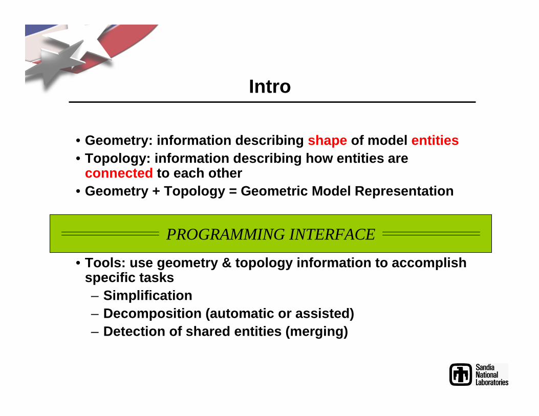
Intro
• Geometry: information describing shape of model entities• Topology: information describing how entities are
connected to each other• Geometry + Topology = Geometric Model Representatio n
• Tools: use geometry & topology information to accom plish specific tasks– Simplification– Decomposition (automatic or assisted)– Detection of shared entities (merging)
PROGRAMMING INTERFACE

GeometryCurve/Surface Shape Rep’s
• Implicit: S = {x : f(x) = 0}; e.g.– Plane: ax + by + cz + d = 0– Sphere: a(x-xo)2 + b(y-yo)2 + c(z-zo)2 + d = 0
• Parametric: S = { f(u) : u ∈∈∈∈ [0,1]x[0,1] }• Definition by construction (surface of revolution)• B-spline curve/surface:
• NURBS curve/surface:
• Issues– Complexity of evaluation– Fitting into “watertight” model
• Trimming• Intersections• Continuity
)()(),( ,
0
,
0
wNuNpwup lj
n
j
kii
m
i∑∑
==
=
)()()()(),( ,
0
,,
0
,
0
,,,0
wNuNhwNuNhpwup lj
n
j
kiji
m
i
lj
n
j
kijiji
m
i∑∑∑∑
====
=

GeometrySurface Shape Representation
• Subdivision Surfaces (Later)

Topological Model “Standard” BREP Entities
Vertex
Edge
Face
Volume
Body
CoEdge
Loop
-
CoFace
-
Shell
+
Basic: Sense: Grouping:
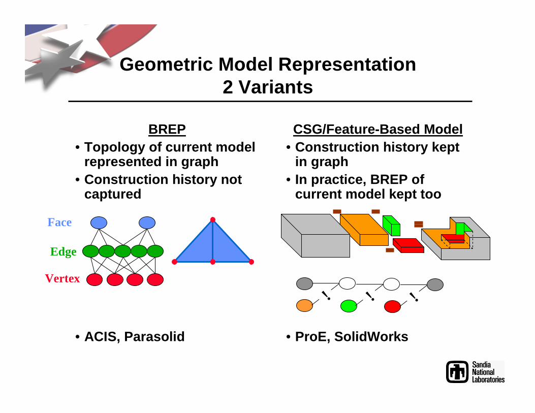
Geometric Model Representation2 Variants
BREP• Topology of current model
represented in graph• Construction history not
captured
• ACIS, Parasolid
CSG/Feature-Based Model• Construction history kept
in graph• In practice, BREP of
current model kept too
• ProE, SolidWorks
Face
Edge
Vertex
! ! !

Virtual Geometry
• Virtual Geometry: – Topology generated from some existing topology– Geometry dependent on some existing geometry– Also: Virtual Topology, Relational Geometry
• Virtual Geometry in CUBIT: – Operators to modify model topology– Operators do not change model geometry

Why Topology Modification
• Topology may be too complex for meshing algorithms.
• B-Rep topology is part of modelers data structure– Therefore, don’t want to
change modeler’s data directly
• Meshing algorithms only see topology directly, get geometry through that– Can change topology
above modeling engine to suit application needs

Virtual Geometry Topological Operations
•Insert/Remove Vertex
–Remove 2-valence vertex only
–±V, ±E
Join/Separate LoopsRemove 2-valence edge only±E, L
Split/Combine LoopsRemove 2-valence edge only±E, ±L , ±F
m
Insert/Remove Vertex-Loop±V, ±L
Euler-Poincaré : V – E + 2F – L – 2S + 2G
VoidIntersects no shellsNo 1-valence edgesCreate new shell and volume
Free faceIntersects no shellsAll 1-valence edgesCreate new shell
Non-manifold faceIntersects one or more shellsAt least one 1-valence edge
Spit volumeIntersects one or more shellsNo 1-valence edgesSplit shell

Virtual GeometryUses
Composite Combination of one or more adjacent entities of equal dimensionHides shared 2-valence lower-dimension geometryCurve, Surface, VolumeEvaluation: find proper underlying entity, evaluate
PartitionOne of several sub-regions of an existing entitySame dimension as underlying entityCurve, Surface, VolumeEvaluation: evaluate (common) underlying entity
Split geometryTessellated definitionBound to existing higher-dimension entityDefines boundary between sub-entities of existing entity.

Virtual GeometryExamples – Small Features
After VG:Before VG:

Virtual GeometryExamples - Multisweep

Virtual GeometryOther Tools
Grafting:
Blend removal:

Model Exchange
• Why exchange models?– Design & analysis tools based on different CAD engi nes
• Various methods used for model exchange– International Graphics Exchange Standard (IGES)
• Points, lines, surfaces• For solids, surfaces must be “stitched”
– STEP• AP203• AP214
– Direct translation from design system– 3rd party translators– STL/facets

Model Validity
• Inter-entity continuity– Topological C0 continuity (model “holds water”)– C1, G1 continuity along curves & surfaces
• Intra-entity geometric continuity– How closely do surface & curve, curve & vertex meet ?– Is parameter space well-behaved?
10001

Model Healing
• Defects come from differing accuracies in modelers• Various approaches to healing:
– Increase accuracy (decrease tolerance) in originati ng modeler– Fill in missing sections with small entities (some IGES readers)– “Tolerant modeling” (Parasolids, ACIS)– Replace mismatched entities with matching ones (e.g . ACIS
tweak surface)– “Virtual topology” - modify topology to fix
topological/geometric problems (Cubit, Ansa, Gambit)• Things to consider:
– Is it a permanent fix or something that has to be r edone after further modifications to originating geometry model ?
– Can healed geometry be transferred to other modeler s?– How much user interaction is required?– What tools are there for detecting invalid geometry ?

Tools
• Model simplification• Merge detection• Model decomposition• Feature extraction

Model Simplification
• Model simplification necessary for:– Removal of geometry artifacts due to translation
(healing)– Removal of geometry features whose size is much
smaller than desired resolution for analysis
• Three approaches:– Geometry/facet-based (Graphics, Sheffer)– Mesh-based (Shephard)– Geometry-based (Sheffer, Shimada, Tautges)

Model SimplificationMesh-, Facet-based
• Facet-based:– Use facets to determine grouping into geometric fea tures– Compute mesh in subsequent meshing step+ Useful for facet-defined models- Calculation expense depends on # of facets- Geometric size information not available in facets, only angle
info• Mesh-based
– Generate mesh on original model at full resolution– Remove mesh entities smaller than desired resolutio n using
edge collapse operations+ Allows direct removal of small analysis features (e .g. edges)- Requires resolution of all design details, which ma y be difficult- Edge collapse is a local mesh operation for tet mes hes, but not
hexes

Model SimplificationGeometry-Based
• A detail suppression method should be:– Automatic– Reversible– Repeatable
• 3 classes of detail removal, by approach:
Removal ByComposite
Blend Suppression
BridgeRemoval

Model SimplificationDefinition of “size” and “small”
• How is “size” defined?
• Small compared to what?– Depends on mesh size – I choose 1/3 user-assigned mesh size, I s/3
Surface: Ss = Dh(s) = 4A/PVolume: Sv = Dh(v) = 6V/A
S = LminS = sqrt(A) S = Dh(s) = 4A/P
Hydraulic Diameter: *Need to account for missing curves on periodic surfaces

Model SimplificationExamples

Bridge Feature Removal: Examples
• Round, square through-holes
• Three intersecting columns

Model SimplificationIssues
• Why not use lfs/MAT?– No fundamental objection, but what about speed?
• Topological detection of through-holes
• Geometric compatibility– Don’t want to restrict direct composite
– Use for prioritization of direct, indirect composites
– Need compatibility threshold for indirect, direct c omposites• Coordination of removals:
– Indirect curve composite, direct surface composite– Blend removal, surface composite
• Grouping of composite operations for efficiency• Better construction of covering faces for bridge fe atures

Merging/Connecting Detection
• Merging/connecting of mesh at material interfaces c an be done in geometry
• Requires identification, merging of coincident geom etry• Merging requires 3 tests:
– Merge test (recursive)– Bounding box test– Internal spatial coincidence test
• Spatial coincidence checks:
|P1 - P2| < εεεε
P1
P2
L1
L2
P1 = L1.eval(s=1/3)P2 = L2.closest_point(P1)
|P1 - P2| < εεεε
S1
S2
P1
P2
P1 = S1.eval(u=1/3, v=1/3)P2 = S2.closest_point(P1)
|P1 - P2| < εεεε
P1 P2

Model Decomposition
• Decomposition used to:– Cut unmeshable model into set of meshable pieces fo r
hexahedral mesh generation– Increase the fraction of a volume meshable using
simpler algorithms (for both speed and mesh quality )• Decomposition is a CAD-like operation, with a few
differences:– Keep both sides– Often need to imprint pieces together– More flexibility in defining cutting surface– User effort in defining surface should be minimized
(most often don’t need to keep cutting surface)

Model DecompositionDefinition of Cutting Surface(s)
• Cut with:– Existing body– Semi-infinite plane, cylinder– Extended model surface– Surface interpolated from loop of edges– Cartesian plane, possibly offset
• Status:– Pro/Engineer 2000i implementing decomposition funct ionality– Typically, other feature-based modelers require cre ation of two
parts and subtraction of surface twice, once with e ach orientation
– CUBIT implements this operation in similar way, but user sees only decomposition results
– (CUBIT) Future plans: enable decomposition of parti ally meshed, merged (non-manifold) models

Feature Extraction
• Definition: A feature is a collection or subset of geometry model that has engineering significance to an application
• Definition of what constitutes a feature is applica tion-dependent:– Manufacturing: boss, slot, chamfer, etc.– Disassembly: assembly, subassembly, disassembly
path, etc.– Mesh generation: extrusion/sweep, submap, map, etc.
• Why is feature extraction necessary? (i.e., why not rely on design features?)– Application dependence of feature definition– Feature information often not transferred between
modelers
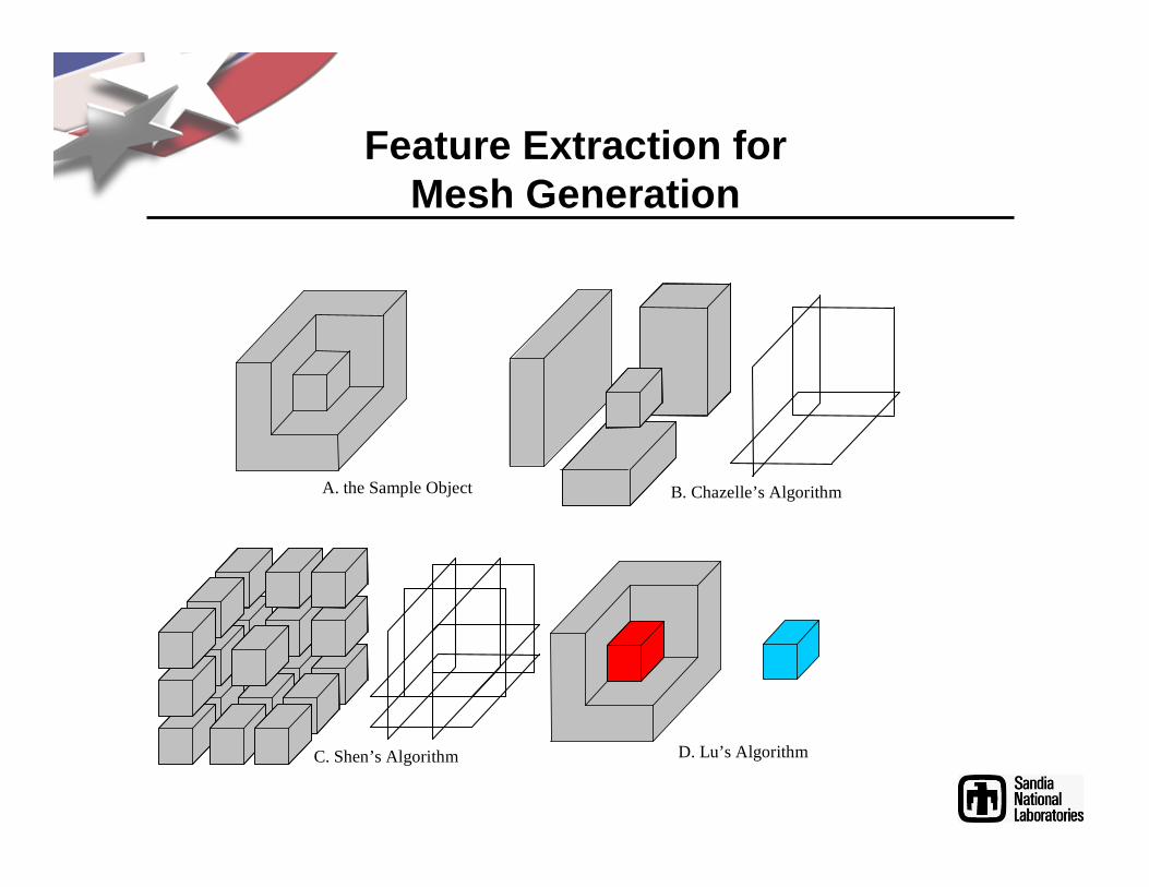
Feature Extraction forMesh Generation
A. the Sample Object B. Chazelle’s Algorithm
C. Shen’s Algorithm D. Lu’s Algorithm

Features - CLoops and CoCLoops PLoop [GADH92]: Pure CLoop, denoted as λp, is a closed link of edges with the same convexity.
HLoop [LIU97]: Hybrid CLoop, denoted as λh, is an open link of edges with the same or mixed convexity.
SLoop [LU98A]: Pseudo CLoop, denoted as λs, is a closed link of edges with mixed convexity.
CoCLoop: a link of coedges
PLoop
HLoop
SLoop
Feature Extraction UsingConcave Edge Loops (Cloops)

Feature-Based DecompositionCutting Surface Generation
• Natural surface interpolation
• Natural surface extrapolation
Cutting surface(Composite)

Feature-Based Decomposition forMesh Generation
• Key ideas:– Decompose as much as necessary and possible, but no t
necessarily completely– Complete decomposition for meshing by hand, or– Complete mesh using 3D meshing algorithm on most
difficult pieces• Problems/issues:
– Choosing “optimal” decomposition from many possible choices
– Local/non-local information– Reliance on automatic 3D meshing algorithm (for hex es)

Programming interfaces

Modelers with API Access
Modeler
Fun
ctio
ns?
Dat
a-st
ruct
ure?
CAD Tools Reference
ACIS x x AutoCAD, IronCAD http://www.spatial.com/pr oducts/3D/modeling/ACIS.html
ParaSolids x x UniGraphics http://www.eds.com/plm/p arasolid/
SolidWorks x SolidWorks http://www.solidworks.com/ pages/services/APISupport.html
Pro/Engineer API Toolkit
x Pro/Engineer http://www.ptc.com
PTC Granite x Pro/Engineer http://www.ptc.com
Catia/Component Application Architecture
x ? Catia http://www.spatial.com/products/CAA

Modeler-Independent APIs
API F
unct
ions
?
Dat
a-st
ruct
ure?
CAD Tools/Modelers Reference
CAPRI x Parasolids, OpenIdeas, Pro/Toolkit, Catia
http://raphael.mit.edu/capri/docs.html
CGM x x ACIS, facet (, SolidWorks, Pro/Toolkit )
http://marie.ep.wisc.edu/~tjtautg/CGM-main.htm
DJINN x (none) http://www.bath.ac.uk/~ensab/GMS/Djinn/djinn.html

ExamplesTest Program: Traverse Topology
• Compile list of vertices, edges, faces and volumes
• Shows how to initialize model, traverse topology• Examples given for:
– ACIS: BREP-based modeler API– SolidWorks: feature-based modeler API– CGM: geometry API

ACIS Example// initialize modeller
outcome result;
result = api_start_modeller (0);
if (! result.ok ()) exit(1);
// read file
ENTITY_LIST entity_list, temp_entity_list;
FILE *file_ptr = fopen(“filename.sat”, “r”);
result = api_restore_entity_list (file_ptr, 1, entity_list); // 1 = text file
if (! result.ok ()) {do_something();}
// traverse geometry
for (int i = 0; i < entity_list.count(); i++) {
ENTITY * entity = entity_list[i] ;
api_get_lumps (entity, temp_entity_list); // lumps
// do something with list…
…
}
// terminate modeller
api_stop_modeller ();

SolidWorks API Example
• Initialization steps:– Add application function(s) to DLL .def file– Start application (start/check for started SolidWor ks app)
• GetActiveObject, ISldWorks::CreateDispatch()
– Add SW menu items, defining application callbacks• Iframe::AddMenu(), Iframe::AddMenuItem()
• Get ModelDoc, RootComponent, Child Components
LPDISPATCH modDisp = p_SldWorks-> GetActiveDoc ();IModelDoc m_ModelDoc( modDisp );LPDISPATCH confD, rootCD;confD = m_ModelDoc. GetActiveConfiguration ();IConfiguration p_actConfig(confD);rootCD = p_actConfig. GetRootComponent ();IComponent p_rootComp(rootCD);
VARIANT compChilds = p_rootComp. GetChildren ();SAFEARRAY* childs = V_ARRAY(&compChilds);LPDISPATCH* childsd;SafeArrayAccessData (childs, (void**)&childsd);long highChildIndex = 0;SafeArrayGetUBound (childs,1, &highChildIndex);

SolidWorks API Example (cont.)
• Traverse assembly
for( int j=0;j<=highChildIndex;j++) { IComponent p_compChilds(childsd[j]); childsd[j]-> AddRef (); LPDISPATCH bodyDisp = p_compChilds. GetBody (); IBody p_Body(bodyDisp); LPDISPATCH faceDisp = p_Body. GetFirstFace (); while(faceDisp) { IFace p_Face(faceDisp); LPDISPATCH faceEntity(p_Face); long loopCount = p_Face. GetLoopCount (); LPDISPATCH loopDisp = p_Face. GetFirstLoop (); while (loopDisp) { ... loopDisp = p_Face. GetNextLoop (); } } }

CGM Example
// initialize modeller
CubitObserver::init_static_observers ();
GeometryTool * gti = GeometryTool::instance ();
// read file
file_ptr = fopen("filename.sat", "r");
status = gti-> import_solid_model (file_ptr, argv[i], "ACIS_SAT");
// traverse geometry
DLBodyList bodies;
gti-> bodies (bodies);
for (int i = bodies.size (); i > 0; i--) {
DLRefVolumeList ref_volumes;
Body * this_body = bodies.get_and_step ();
this_body-> ref_volumes (ref_volumes);
// do something with volumes...
}
// terminate modeller
delete gti;

Topological Model DifferencesAmong Modelers/APIs
• Modelers
• APIs
Modeler Vertices? CoEdges? CoFaces? Body?ACIS y y y 2 y
Parasolids y y y 2 yOpenIdeas y y y nPro/Toolkit n y 3 n n 1
Catia AASolidWorks API y y n n 1
API Vertices? CoEdges? CoFaces? Body?DJINN y y n yCGM y y y y
CAPRI y n 3 n4 n
1. Either does not have Body, or Body corresponds exactly to Volume.2. Has CoFace, but CoFace is not the same “stature” as a Face or CoEdge.3. Does not explicitly define CoEdge, but can retrieve Edge sense with respect to Face.4. Does not allow faces shared between volumes.

Other DifferencesManifold/Non-Manif. Topology
• ACIS, Parasolids– “special” modules for representing manifold/non-
manifold topology– CoFaces represented with subordinate entities or wit h
“sense” functions• Pro/Toolkit, SolidWorks API
– no support for non-manifold geometry representation– non-manifold geometry detection could be aided by
associations designated by user in model• CAPRI, DJINN:
– No support for non-manifold geometry• CGM:
– Support for both detection and representation

Other DifferencesTopology Quirks
• Periodic geometry– ACIS, Parasolids, SolidWorks API, CGM: yes– Pro/Toolkit, CAPRI: no
• Other quirks– Pro/Toolkit: disjoint faces

Classes of API Functionality
• Query-only– CAPRI*– DJINN
• Limited modification– Pro/Toolkit
• Full modification capability– ACIS– Parasolids– SolidWorks– CGM

Feature-Based Modeler APIs(SolidWorks API, Pro/Toolkit)
• Feature-based modelers expose “features”, which may or may not be represented fully in final topology– E.g. nested slots
• Do APIs expose model topology, feature topology, or both?– SolidWorks API: both– Pro/Toolkit: both

ReferencesACIS Healing Husk, Spatial Technology Inc., http:// www.spatial.com.C. G. Armstrong, S.J. Bridgett, R.I. Donaghy, R.W. M cCune, R.M. McKeag and D.J.
Robinson , Techniques for Interactive and Automatic Idealisation of CAD, in proc. Numerical Grid Generation in Computational Field Si mulations, Ed. M. Cross., B. K.Soni, J. F. Thompson, J. Hauser, P. R. Eiseman, Pro ceedings of the 6th International Conference, held at the University of Greenwich, pp .643-662, July 1998.
G. Barequet, Subodb Kumar, "Repairing CAD Models", Pro ceeding IEEE Visualization, Phoenix, AZ, IEEE, pp.363-370, October 1997.
R. J. Donaghy, W. McCune, S.J. Bridgett, C.G. Armstr ong, D.J. Robinson and R.M.McKeag, "Dimensional Reduction of Analysis Models", 5th International Meshing Roundtable, Sandia National Laboratories, pp.307-32 0, October 1996.
M. Etzion, A. Rappaport, “Computing the Voronoi Diagram of a 3-D Polyhedron by Separate Computation of its Symbolic and Geometric Parts”, Fifth Symposium on Solid Modeling, Ann Arbor, MI (1999).
Y. Lu, R. Gadh and T. J. Tautges, ‘Feature Decomposit ion for Hexahedral Meshing’, to appear, 1999 ASME Design Automation Conference, Las Vegas, Nevada, Sept. 12-15, 1999
A. V. Mobley, Michael P. Carroll, and Scott A. Canan n, "An Object Oriented Approach to Geometry Defeaturing for Finite Element Meshing", 7th International Meshing Roundtable, Sandia National Labs, pp.547-563, Octob er 1998.
J. M. Reddy, G. M. Turkiyyah, “Computation of 3D ske letons using a generalizedDelaunay triangulation technique”, Computer Aided De sign, 27(9):677-694 (1995).

References (cont.)
A. Sheffer, Ted Blacker and Michel Bercovier, "Cluste ring: Automated Detail Suppression Using Virtual Topology", AMD-Vol. 220, Trends in Unstructured Mesh Generation, ASME, pp.57-64, July 1997
M. S. Shephard, M.W. Beau and R.M. O'Bara, "Revisiti ng the Elimination of the Adverse Effects of Small Model Features in Automatically Ge nerated Meshes", Proceedings, 7th International Meshing Roundtable, Sandia Nation al Labs, SAND98-2250, Oct. 1998.
T. J. Tautges, Shang-sheng Liu, Yong Lu, Jason Kraftch eck and Rajit Gadh, “Feature Recognition Applications in Mesh Generation”, Trend s in Unstructured Mesh Generation, ASME Applied Mechanics Division, Volume AMD-Vol 220, 1997.
K. Versprille, “Visual Portals: Unlocking Product In formation”, DH Brown & Associates report, 2/26/1999, http://www.dhbrown.com/cffiles/RPPage.cfm?ID=101&DO C=7334541.
Mäntylä, M. (1988), An introduction to solid modeli ng, Computer Science Press.
Hoffmann, C.M (1989), Solid and Geometric Modeling, Morgan Kaufmann Publishers.
Farin, G (1985), Curves and Surfaces for Computer A ided Geometric Design, Academic Press, Boston.
http://www.mrl.nyu.edu/~dzorin/sig00course/

Acknowledgements
• 12th IMR Steering Committee• D. Zorin, NYU• P. Schroeder, Cal Tech• M. Sabin, Numerical Geometry Ltd