Embed Size (px)
Citation preview

Geometric Dimensioning and
Tolerancing
Engineering III

GD&T
• Geometric Dimensioning & Tolerancing
is an international engineering language
that is used on engineering drawings to
describe products in three dimensions.
• GD&T is a precise mathematical
language that describes the form,
orientation and location of part
features in zones of tolerance.

Geometric Dimensioning
• Geometric dimensioning and
tolerancing is a three-dimensional,
mathematically-based system.
• Within this system, features on an
object are oriented or located relative to
a Cartesian Coordinate System or
Datum Reference Frame.

Geometric Dimensioning
• Feature Control Frames are used to
specify acceptable tolerance zones for the
features relative to the Datum Reference
Frame.
.001 AM B C

• Like any language, it takes some time to
learn it well.
• Some personnel might learn it in a
conversational way.
• Others can read it but not write it.
• Others might be experts.
GD&T

Advantages of GD&T
• Clearer intent of the designer.
• Better communication throughout the
design process.
– Better choices for manufacturing/machining.
– Better/more accurate choices for inspection.
• Leaves almost nothing that can be
interpreted more than one way.

Example Drawing

Establish Datums

Control Datums

Position the Machined Hole

Control the Other Surfaces
Datum Reference Frame
• The DRF is made up of three mutually perpendicular planes (similar to a Cartesian Coordinate System).
• These planes exist in theory only.
• Planes are established relative to features on the actual object.

Datum Terminology
• Datum - A theoretically exact point, axis, or plane derived from the true geometric counterpart of a specified datum feature. A datum is the origin from which the location or geometric characteristics of features of a part are established.
• Datum Feature - An actual feature of a part that is used to establish a datum.

Datum Terminology
• Datum Feature Symbol - The symbolic means of indicating a datum feature. It consists of a capital letter enclosed in a square frame and a leader line extending from the frame to the concerned feature, terminating with a triangle.
• Datum Feature Simulator - A surface of adequately precise form contacting the datum feature(s) and used to establish the simulated datum(s). Typically this surface must be at least 10 times better in quality (flatness) than the tolerances specified on the drawing

Datum Terminology

Features
• Feature - The general term applied to a
physical portion of a part, such as a
surface, pin, tab, hole, or slot.
• Feature of size (feature with size) - A
cylindrical or spherical surface, or a set
of two opposed elements or opposed
parallel surfaces, associated with a size
dimension.
• Feature without size - Typically this is
a planar surface.

Features With and Without Size
Features
with size
Features
without size
Feature
without size

Applying Datums to a
Feature without Size

Applying Datums to a
Feature with SizeDatum C is the
median plane of
the slot
Datum D is
the axis of
the cylinder
Datum B is the
axis of the hole

Geometric Characteristic
Symbols

Form Tolerances - Straightness
• Each longitudinal
element on the
surface must lie
between two parallel
lines 0.05 apart.
• The shape of the
tolerance zone is a
2D area between
two parallel lines.
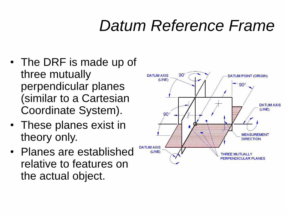
Form Tolerances - Flatness
• All points on the
surface must lie
between two parallel
planes 0.05 apart.
• The shape of the
tolerance zone is a
3D area between
two parallel planes.

Form Tolerances - Circularity
• All points on the surface must lie between two concentric circles 0.05 apart.
• The shape of the tolerance zone is a 2D area between two concentric circles.

Form Tolerances - Cylindricity
• All points on the surface must lie between two concentric cylinders 0.05 apart.
• The shape of the tolerance zone is a 3D area between two concentric cylinders.

Profile of a Line Tolerance
• Each point on the specified path must lie between two parallel contours 0.05 apart (0.025 on each side of path).
• The shape of the tolerance zone is a 2D area between the two contours.
• Perfect geometry is located with basic dimensions.

Profile of a Surface Tolerance
• Each point on the surface must lie between two parallel/ concentric contours 0.05 apart (0.025 on each side of surface).
• The shape of the tolerance zone is a 3D area between the two contours.
• Perfect geometry is located with basic dimensions.

Orientation Tolerances - Angularity
• All points on the surface must lie between two parallel planes 0.05 apart.
• Perfect geometry is located using basic dimensions.
• The shape of the tolerance zone is a 3D area between two parallel planes.

Orientation Tolerances -
Perpendicularity
• All points on the
surface must lie
between two parallel
planes 0.05 apart.
• The shape of the
tolerance zone is a
3D area between
two parallel planes.

Orientation Tolerances -
Parallelism
• All points on the
surface must lie
between two parallel
planes 0.05 apart.
• The shape of the
tolerance zone is a
3D area between
two parallel planes.
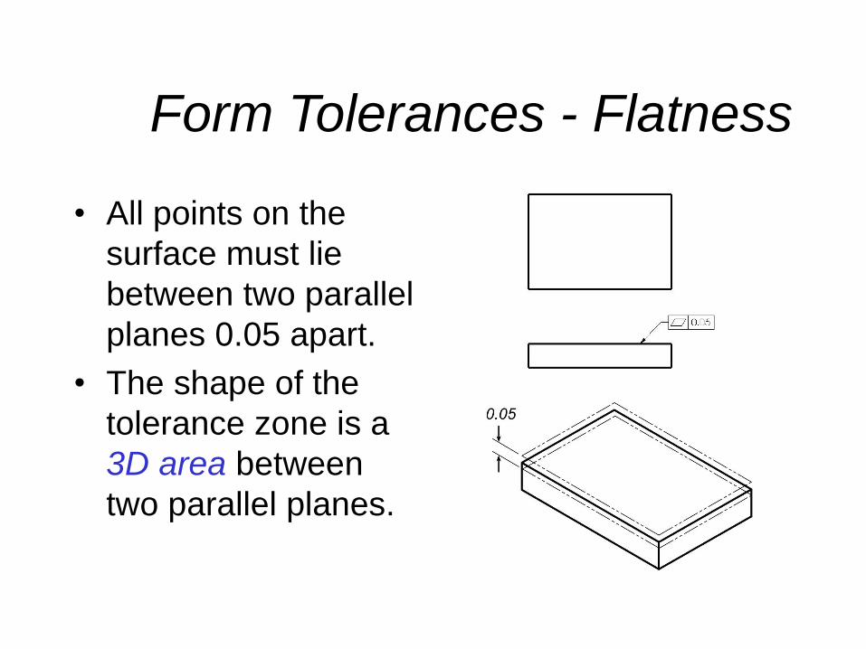
Location Tolerances - Position
• All points on the axis
must lie within a
cylinder with a diameter
of 0.001 at maximum
material condition.
• The cylinder is located
with basic dimensions
from the datums.
• The shape of the
tolerance zone is a 3D
area within the cylinder.

Location Tolerances -
Concentricity
• All points on the axis
must lie within a
cylinder with a
diameter of 0.4
relative to the datum
axis.
• The shape of the
tolerance zone is a
3D area within the
cylinder.

Location Tolerances - Symmetry
• All points on the feature’s median plane must lie between two parallel planes defined by the datum’s median plane.
• The shape of the tolerance zone is a 3D area between the two planes.

Runout Tolerances - Circular
• All points on the surface
must lie between two
concentric circles 0.02
apart relative to the
datum feature.
• The shape of the
tolerance zone is the
2D area between the
two concentric circles.

Runout Tolerances - Total
• All points on the surface
must lie between two
concentric cylinders
0.02 apart relative to
the datum feature.
• The shape of the
tolerance zone is the
3D area between the
two concentric
cylinders.

Symbols
Material Condition Modifiers
• Maximum Material Condition – The geometric tolerance applies only at the feature’s maximum material within the stated limits of size.
• Least Material Condition – The geometric tolerance applies only at the feature’s least material within the stated limits of size.
• Regardless of Feature Size – The geometric tolerance applies at any increment of size of the feature within its size tolerance.

MMC & LMC

Feature Control Frame
GEOMETRIC SYMBOL
TOLERANCE INFORMATION
DATUM REFERENCES
THE FEATURE MUST BE
WITHIN RELATIVE TO

Feature Control Frame
• The feature must be parallel
• within a five-hundredths of a millimeter
tolerance zone
• relative to datum feature A
0.05 A

Feature Control Frame
• The feature must be positioned
• within a one-thousandth of an inch,
cylindrical tolerance zone at maximum
material condition
• relative to primary datum feature A,
secondary datum feature B, and tertiary
datum feature C.
.001 AM B C

Standards for Millimeters
• Show leading
zeros for values
less than 1 unit
• Do not show
trailing zeros

Standards for Inches
• Do not show
leading zeros for
values less than
1 unit
• Show trailing
zeros equal to
the precision of
the drawing