Embed Size (px)
Citation preview

SAND 93-1373Unlimited ReleasePrinted July 1993
GENSHELL:A Genesis Database 2D to
3D Shell Transformation Program
Gregory D. SjaardemaSolid and Structural Mechanics Department
Sandia National LaboratoriesAlbuquerque, New Mexico 87185
Abstract
GENSHELL is a three-dimensional shell mesh generation program. The three-dimensional shell mesh is generated by mapping a two-dimensionalquadrilateral mesh into three dimensions according to one of several types oftransformations: translation, mapping onto a spherical, ellipsoidal, orcylindrical surface, and mapping onto a user-defined spline surface. Thegenerated three-dimensional mesh can then be reoriented by offsetting,reflecting about an axis, revolving about an axis, and scaling the coordinates.GENSHELL can be used to mesh complex three-dimensional geometriescomposed of several sections when the sections can be defined in terms oftransformations of two-dimensional geometries. The codeGJOIN is then usedto join the separate sections into a single body.GENSHELL updates theEXODUS quality assurance and information records to help track the codesand files used to generate the mesh.GENSHELL reads and writes two-dimensional and three-dimensional mesh databases in theGENESIS databaseformat; therefore, it is compatible with the preprocessing, postprocessing, andanalysis codes in the Sandia National Laboratories Engineering Analysis CodeAccess System (SEACAS).
DistributionCategory UC-405

Intentionally Left Blank
4

779
0
128
223
27
1
7
Contents
1 Introduction.........................................................................................................1.1 SEACAS Mesh Generation Toolbox ............................................................1.2 Introduction to the GENESIS File Format ....................................................1.3 Overview of Capabilities in GENSHELL ..................................................... 91.4 Organization of Report ................................................................................. 1
2 Command Input .................................................................................................. 12.1 Mesh Transformation .................................................................................... 12.2 Mesh Orientation .......................................................................................... 12.3 Modification or Creation of Material, Nodeset, or Sideset IDs .................... 222.4 Information and Processing ..........................................................................2.5 Order of Transformation ............................................................................... 2
3 GENSHELL Example Input and Output ......................................................... 25
4 References ............................................................................................................
A The GENESIS Database Format ...................................................................... 29
B Command Summary .......................................................................................... 3
C GENSHELL Details ........................................................................................... 35
Figures
Figure 1. Schematic of SEACAS Mesh Generation Process ...............................Figure 2. Illustration ofWARP POINT transformation ....................................... 13Figure 3. Illustration ofWARP YAXIS MAP transformation ............................... 14Figure 4. Illustration ofWARP YAXIS VERTICAL transformation ..................... 15Figure 5. Illustration ofWARP ELLIPSE transformation ................................... 16Figure 6. Illustration ofSPLINE (SPHERICAL) transformation ......................... 19Figure 7. Illustration ofSPLINE (XSWEEP) transformation .............................. 20Figure 8. Illustration ofSPLINE (YSWEEP) transformation............................... 21
5

Intentionally Left Blank
6

esh bylatingmeshnto asplinerato-
n
e that
n below,
1 Introduction
GENSHELL is a mesh generation program that creates a three-dimensional shell mtransforming a two-dimensional mesh. Four transformations are available: (1) transnormal to the plane of the two-dimensional mesh, (2) mapping the two-dimensional onto a spherical or ellipsoidal surface, (3) mapping the two-dimensional mesh ocylindrical surface, and (4) mapping the two-dimensional mesh onto a user-defined surface.GENSHELL is one of the mesh generation tools in the Sandia National Labories Engineering Analysis Code Access System (SEACAS) [1].
1.1 Sandia Engineering Analysis Code Access System Mesh GeneratioToolbox
GENSHELL is typically used with the other SEACAS mesh generation codesFASTQ [2],GEN3D [3], GREPOS [4], GJOIN [5], andAprepro [6]. Figure 1 shows the structure of thSEACAS mesh generation toolbox. The basic premise underlying this toolbox iscomplicated geometries can be generated using a set of small specialized codes.
Each of these codes has a specialized purpose, a short synopsis of each code is givefor more information consult the referenced documentation.
GEN3D Transforms a two-dimensionalGENESIS database into athree-dimensionalGENESIS database. Several
Figure 1. Schematic of SEACAS Mesh Generation Process
MAKE
PATRANFASTQ
3D GENESIS
PATRAN
GEN3D
GJOIN GJOINGREPOS
FASTQ BLOT
2D GENESIS
ApreproAprepro Analysis
INPUT FILES
GREPOS
GENSHELL
7
meshe fromsed ofional
nagingoblems
imef theen
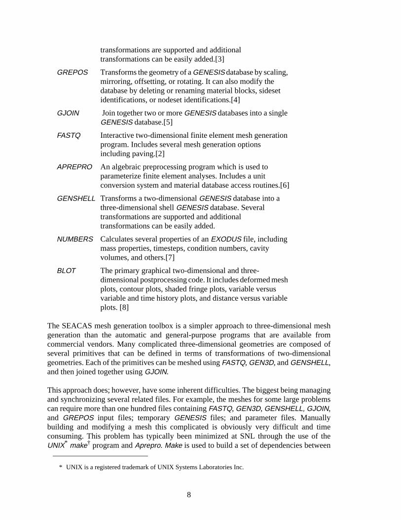
transformations are supported and additionaltransformations can be easily added.[3]
GREPOS Transforms the geometry of aGENESIS database by scaling,mirroring, offsetting, or rotating. It can also modify thedatabase by deleting or renaming material blocks, sidesetidentifications, or nodeset identifications.[4]
GJOIN Join together two or moreGENESIS databases into a singleGENESIS database.[5]
FASTQ Interactive two-dimensional finite element mesh generationprogram. Includes several mesh generation optionsincluding paving.[2]
APREPRO An algebraic preprocessing program which is used toparameterize finite element analyses. Includes a unitconversion system and material database access routines.[6]
GENSHELL Transforms a two-dimensionalGENESIS database into athree-dimensional shellGENESIS database. Severaltransformations are supported and additionaltransformations can be easily added.
NUMBERS Calculates several properties of anEXODUS file, includingmass properties, timesteps, condition numbers, cavityvolumes, and others.[7]
BLOT The primary graphical two-dimensional and three-dimensional postprocessing code. It includes deformed meshplots, contour plots, shaded fringe plots, variable versusvariable and time history plots, and distance versus variableplots. [8]
The SEACAS mesh generation toolbox is a simpler approach to three-dimensionalgeneration than the automatic and general-purpose programs that are availablcommercial vendors. Many complicated three-dimensional geometries are composeveral primitives that can be defined in terms of transformations of two-dimensgeometries. Each of the primitives can be meshed usingFASTQ, GEN3D, andGENSHELL,and then joined together usingGJOIN.
This approach does; however, have some inherent difficulties. The biggest being maand synchronizing several related files. For example, the meshes for some large prcan require more than one hundred files containingFASTQ, GEN3D, GENSHELL, GJOIN,and GREPOS input files; temporaryGENESIS files; and parameter files. Manuallybuilding and modifying a mesh this complicated is obviously very difficult and tconsuming. This problem has typically been minimized at SNL through the use oUNIX* make† program andAprepro. Make is used to build a set of dependencies betwe
* UNIX is a registered trademark of UNIX Systems Laboratories Inc.
8

neededteredthepieces few
ization
tionaler readh
ationl typeslication more
ing asional
erate
sionalal, or
roing,
the various pieces of the finite element model. The analyst can then change files as and simply typemake mesh to generate the mesh. If the dependencies have been encorrectly, make will rebuild only those portions of the mesh that are affected by changed file. The synchronization problem (that is, ensuring that all of the separate have compatible dimensions and discretization) is typically solved by creating aparameter files which contain key dimensions and discretization information.Aprepro isthen used to preprocess the input files and insert the key dimensions and discretinformation into the input files.
1.2 Introduction to the GENESIS File Format
TheGENESIS mesh database file format is the geometry definition portion of theEXODUSdatabase file format used in the Engineering Sciences Center at Sandia NaLaboratories. All of the mesh generation programs in the Engineering Sciences Centand write files in theGENESIS format, which allows great flexibility in the choice of mesgeneration, file translation, and graphical processing.
TheGENESIS file contains the data to describe a finite element mesh including the locof the nodal points, the connectivity of the nodes that form each element, the materiaof each element, and the boundary condition data which are used to specify load apppoints and nodal constraints. The reader is referred to References [9] and [10] forinformation.
1.3 Overview of Capabilities inGENSHELL
With GENSHELL, the user can create a three-dimensional shell mesh by transformtwo-dimensional mesh; change the orientation and size of the resulting three-dimenmesh; and change material block, nodeset, and sideset IDs.GENSHELL also updates theEXODUS QA and information records to help track the codes and files used to genthe mesh.
Transformations:The three-dimensional shell mesh can be transformed by translation of a two-dimenmesh, or by mapping a two-dimensional mesh onto a spherical, cylindrical, ellipsoiduser-defined spline surface.
Orientation:The orientation of the mesh can be changed by revolving, offsetting, reflecting, zeand scaling the nodal coordinates of the original mesh.
† See your UNIX documentation for more information on make. Typically this is done by enteringthe commandman 1 make
9

IDs. inputD (that
nsionalont orvity ofnd the
le-utput
mesh
ame as
whichnds to
Material Blocks, Sidesets, and Nodesets:In the SEACAS system, material properties are input according to material blockSimilarly, boundary conditions are associated with sideset and nodeset IDs. Thematerial block IDs, sideset IDs, and nodeset IDs can be changed to a new unique Iis they can be changed, but not combined).
The user may also create sets of the nodes on the front or back of the three-dimemesh. The front or back nodeset contains all of the two-dimensional nodes. The frback sideset also contains all of the two-dimensional nodes; however, the connectithe sideset is such that the right-hand-rule specifies the normal of the front sideset areverse holds for the back sideset.
Quality Assurance (QA) and Information Records:A QA record for theGENSHELL program is added to the input QA record(s), and the finame of the input file is added to the information records that are written to the omesh. The information record is prefaced byGENSHELL to help in identification. Theserecords, which are explained in Reference [9], are useful in tracing the evolution of aduring the mesh generation process.
Node and Element Numbering:The node and element numbering of the generated three-dimensional mesh is the sthe input two-dimensional mesh.
Element Attributes:The generated three-dimensional shell elements have a single element attributespecifies the thickness of the shell. This attribute is set by the transformation commathe user-specified thickness.
1.4 Organization of Report
The remainder of this report is organized as follows:
• Chapter 2 describes the command input and valid commands, and
• Chapter 3 presents a few short examples illustratingGENSHELL use.
Three appendices are contained in this report.
• Appendix A is a code segment defining theGENESIS binary database format,
• Appendix B is a summary of the commands inGENSHELL, and
• Appendix C describes the specifics ofGENSHELL including executing it, obtainingit, compiling it, and quality assurance.
10

ngsyntax
re
cters
e is
r of
It may other
meterslue is
be iner
n
s
mma
2 Command Input
The user directs the execution ofGENSHELL by entering commands to set processiparameters. The commands are in free-format and must adhere to the following rules.
• Valid delimiters are a comma or one or more blanks.
• Either lowercase or uppercase letters are acceptable, but lowercase letters aconverted to uppercase.
• A “$” character in any command line starts a comment. The “$” and any charafollowing it on the same line are ignored.
• A command may be continued over several lines with an “* ” character. The “* ”and any characters following it on the current line are ignored and the next linappended to the current line.
Each command has an action keyword or “verb” followed by a variable numbeparameters.
An action keyword or verb is a character string matching one of the valid commands. be abbreviated as long as enough characters are used to distinguish it fromcommands.
The meaning and type of the parameters depend on the command verb. Most paraare optional. If an optional parameter field is blank, a command-dependent default vasupplied. Valid entries for parameters are:
• A numeric parameter may be a real number or an integer. A real number mayany legal FORTRAN numeric format (e.g., 1, 0.2, -1E-2). An integer parametmay be in any legal integer format*.
• A string parameter is a literal character string. Most string parameters may beabbreviated.
The notation conventions used in the command descriptions are:
• The command verb is in bold type.
• A literal string is in all uppercaseSANSERIF type and should be entered as show(or abbreviated).
• The value of a parameter is represented by the parameter name initalics.
• A literal string in square brackets (“[ ]”) represents a parameter option which iomitted entirely (including any following comma) if not appropriate. Theseparameters are distinct from most parameters in that they do not require a co
* Arithmetic equations, variables, and control structures can be used in the input files if the-aprepro option is used. See the Aprepro manual for more information.
11

of ainitial
e
Z
te
h
e
he
al
ll
as a place holder to request the default value.
• The default value of a parameter is in angle brackets (“< >”). The initial value parameter set by a command is usually the default parameter value. If not, the setting is given in the command description.
2.1 Mesh Transformation
TRANSLATE thickness<1.0>
TRANSLATE sets the thickness of the 3D shell mesh tothickness. This commandsupersedes previous transformation commands. The following command sets ththickness of the generated shell elements to 1.5:
TRANSLATE 1.5
All of the X and Y coordinates remain the same as those in the 2D mesh; the coordinates are set equal to 0.0
WARP POINT thickness<1.0>, radius<no default>
WARP POINT causes the 2D mesh to be mapped onto a spherical surface to creathe 3D mesh. The spherical surface has a radius of curvature equal toradius. Thecenter of curvature is located on the z-axis, and it is a distance ofradiusabove theX-Y plane. The total thickness isthickness. Note thatradius must be greater thanthe maximum distance from the z-axis to the boundary of the 2D mesh. Thiscommand supersedes previous transformation commands. The mestransformation is performed in two parts. First, the warped nodal positions (xw,yw, zw) are calculated by mapping the original 2D mesh onto a spherical surfacwith a radius of curvature equal toradius. The original x and y coordinates of the2D mesh remain at the same values; the z coordinate is calculated such that tdistance to the center of curvature is equal toradius.
The warped nodal positions are projections parallel to the z-axis onto a sphericsurface of radiusradius. A square mesh warped with the command"WARPPOINT 1 2" is shown in Figure 2.
WARP XAXIS [MAP|VERTICAL] thickness<1.0>, radius<no default>WARP YAXIS [MAP|VERTICAL] thickness<1.0>, radius<no default>
This second form of the WARP command maps the 2D mesh to a cylindricasurface centered on either the X or Y axis to create the 3D mesh. The cylindricasurface has a radius of curvature equal toradius. The center of curvature is located
xw x2D=
yw y2D=
zw radius radius2
x2D2
– y2D2
––=
12

reen
a distance ofradius above the X-Y plane. The total thickness isthickness. Thiscommand supersedes previous transformation commands.
If MAP is specified, the warped nodal positions (xw, yw, zw) are calculated bymapping the original 2D mesh onto a cylinder about the specified axis with aradius of curvature equal toradius. If XAXIS is specified, then the original X-coordinate remains at the same value. The generated Y and Z coordinates acalculated such that the distance from the generated node to the X-Z planmeasured along the cylindrical surface is equal to the X coordinate of the node ithe 2D mesh. If the Y-axis is specified, the X’s and Y’s are switched in the abovediscussion. The resulting 3D mesh will have an cylindrical angle ofradians if warped about the Y axis, or radians if warped about the
Figure 2. Illustration ofWARP POINT transformation
X
Z
center at Z = radius
length = radius
Y
xmax radius⁄ymax radius⁄
13

s
e
X axis, where and are the maximum X and Y coordinates in the 2Dmesh. A square mesh warped with the command"WARP YAXIS MAP 1 1" isshown in Figure 2.
If VERTICAL is specified, the warped nodal positions xw, yw, zw) are againcalculated by mapping the original 2D mesh onto a cylinder about the specifiedaxis with a radius of curvature equal toradius. However, for this case, both theoriginal X- and Y-coordinates remain at the same value and the Z-coordinate icalculated as:
(1)
for anXAXIS warp. The y is replaced byx if a YAXIS warp is specified. A squaremesh warped with the command"WARP YAXIS VERTICAL 1 1" is shown inFigure 2. Note that since the original X and Y coordinates remain the same in thtransformed mesh, the elements elongate in the mapped mesh.
Figure 3. Illustration ofWARP YAXIS MAP transformation
xmax ymax
X
length = radius
distance
Z
axis at Z = radius X Distance along warped surfaceequals original X distance in 2Dmesh.
Y
zw radius radius2 y2D2––=
14
e
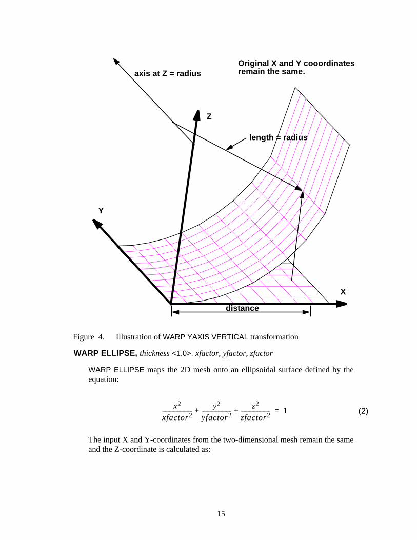
WARP ELLIPSE, thickness<1.0>, xfactor, yfactor, zfactor
WARP ELLIPSE maps the 2D mesh onto an ellipsoidal surface defined by theequation:
(2)
The input X and Y-coordinates from the two-dimensional mesh remain the samand the Z-coordinate is calculated as:
Figure 4. Illustration ofWARP YAXIS VERTICAL transformation
X
length = radius
distance
Z
axis at Z = radiusOriginal X and Y cooordinatesremain the same.
Y
x2
xfactor2---------------------- y2
yfactor2---------------------- z2
zfactor2---------------------+ + 1=
15
e
e
e
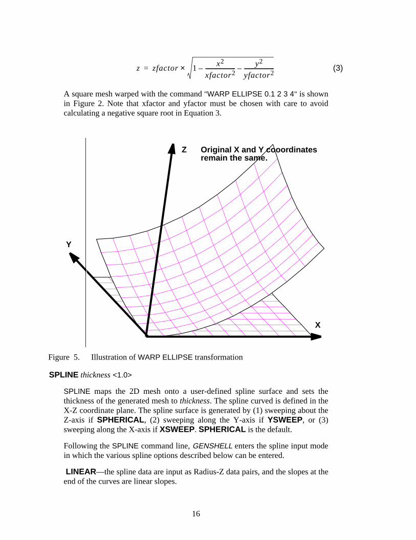
(3)
A square mesh warped with the command"WARP ELLIPSE 0.1 2 3 4" is shownin Figure 2. Note that xfactor and yfactor must be chosen with care to avoidcalculating a negative square root in Equation 3.
SPLINE thickness<1.0>
SPLINE maps the 2D mesh onto a user-defined spline surface and sets ththickness of the generated mesh tothickness. The spline curved is defined in theX-Z coordinate plane. The spline surface is generated by (1) sweeping about thZ-axis if SPHERICAL , (2) sweeping along the Y-axis ifYSWEEP, or (3)sweeping along the X-axis ifXSWEEP. SPHERICAL is the default.
Following theSPLINE command line,GENSHELL enters the spline input modein which the various spline options described below can be entered.
LINEAR—the spline data are input as Radius-Z data pairs, and the slopes at thend of the curves are linear slopes.
Figure 5. Illustration ofWARP ELLIPSE transformation
z zfactor 1 x2
xfactor2----------------------– y2
yfactor2----------------------–×=
X
Y
Z Original X and Y cooordinatesremain the same.
16

,in
e
e
e
e
ine
ine
e
ANGULAR— the spline data are input as Theta(degrees)-Distance data pairswhere Theta is the angle between the X-Y plane and the line between the orig(X = Y = Z = 0) and the defined point, and Distance is the length of this line. Theslopes at the end of the curves are relative to this curve.
FRONT—the curve data and slope specifications up to the nextBACK, END, orEXIT command will be for theFRONT spline. The front surface Z values aregreater (more positive) than the back surface Z values. NOTE: InGENSHELL,only the front spline data are used, theBACK keyword is retained so that splinedefinitions fromGEN3D files can be used inGENSHELL.
BACK —In GENSHELL, only the front spline data are used, theBACK keywordis retained so that spline definitions fromGEN3D files can be used inGENSHELL.
LEFT slope—the parameterslope specifies the slope of the spline curve at theLEFT end of the curve. The slope is measured in the same units specified in thANGULAR or LINEAR command. If the slope is not specified, the end conditionsof the curve will be set such that the second derivative is equal to zero which is thso-called natural cubic spline.
RIGHT slope—the parameterslope specifies the slope of the spline curve at theRIGHT end of the curve. The slope is measured in the same units specified in thANGULAR or LINEAR command. If the slope is not specified, the end conditionsof the curve will be set such that the second derivative is equal to zero which is thso-called natural cubic spline.
SPHERICAL—The spline surface is sweptabout the Z-axis to generate thesurface onto which the two-dimensional mesh is mapped. This is the default.
XSWEEP—The spline surface is sweptalong the X-axis to generate the surfaceonto which the two-dimensional mesh is mapped. The X-coordinates in thegenerated mesh are the same as the X-coordinates in the original mesh. The splsurface is input as either Y-Z data pairs ifLINEAR is selected, or asTheta(degrees)-Distance pairs in the Y-Z plane ifANGULAR is selected.
YSWEEP—The spline surface is sweptalong the Y-axis to generate the surfaceonto which the two-dimensional mesh is mapped. The Y-coordinates in thegenerated mesh are the same as the Y-coordinates in the original mesh. The splsurface is input as either X-Z data pairs ifLINEAR is selected, or asTheta(degrees)-Distance pairs in the X-Z plane ifANGULAR is selected.
SCALE—Stretch the X-Y coordinates of the input mesh so that the X-Y extentof the output mesh matches the extent of the spline. That is, the 2D mesh will bstretched to fit the surface defined by the spline. This is the default.
NOSCALE—The X-Y coordinates of the 2D mesh are the X-Y coordinates of hteoutput 3D mesh. This option can only be used with theLINEAR spline.
EXIT or END—terminate spline input mode and return to generalGENSHELL
17

m
ens,ote
e
-e
e-l
.
command processing.
GENSHELL does not check the validity of the input spline curve; it is possible togenerate a mesh with invalid elements if the spline curve crosses itself.
The following procedure is used to generate a three-dimensional shell mesh froa two dimensional mesh using the SPLINE option.
1. Generate the cubic spline parameters to fit the data entered by the user.
2. Calculate the cumulative chord lengthsdi of each segment of the spline. The
chord length of each segment is calculated as the straight line distance betweeach of the entered data points. This is a good approximation for smooth curvebut it underestimates the distance for non-smooth curves. If the spline does nbegin at the Z axis, the minimum distance of the spline is equal to the distancfrom the Z axis. Note that the minimum distance is equal tod
1, and the maximum
distance is equal todNS
whereNS is the number of points defining the curve.
3. Determine the minimum and maximum extent of the input two-dimensionalmesh. IfSPHERICAL is specified, the extents are radii measured form the pointX=Y=0; if XSWEEP or YSWEEP are specified, the extents are simply theminimum and maximum coordinates. If the spline curve starts at 0.0, theminimum extent of the two-dimensional mesh is also set to 0.0
4. The two-dimensional mesh is mapped onto the spline surface such that thmaximum mesh extent (m
max) is mapped to the outside edge of the spline surface,
and the minimum mesh extent (mmin
) is mapped to the inside edge of the splinesurface. This mapping defines a coordinate transformation where the twodimensional mesh is uniformly stretched or shrunk onto the spline surface. Notthat the distance is measured along the spline surface. IfSPHERICAL is specified,both the X- and Y-coordinates are transformed; however, the generated thredimensional node will have the same polar angle in the X-Y plane as the originatwo-dimensional node. IfXSWEEP is specified, only the Y-coordinates aretransformed; and ifYSWEEP is specified, only the X-coordinates aretransformed.
Figures 2, 2, and 2 show a square mesh mapped ontoSPHERICAL spline surface,anXSWEEP spline surface, and aYSWEEP spline surface, respectively.
THICKNESS thickness <1.0>
THICKNESS sets the thickness of the generated shell elements tothickness. Amesh transformation command must be entered prior to this commandSubsequent mesh transformation commands override this value.
2.2 Mesh Orientation
MIRROR axis1, axis
2,… <No Default>
18

et
MIRROR RESET <no reflections>
MIRROR causes the mesh to be reflected about a coordinate plane. Eachaxisparameter specifies which coordinates (X or Y or Z) will be modified. Reflectionsare performed after the mesh has been repositioned by theREVOLVE andOFFSET commands.
TheMIRROR RESET command resets to no reflection.
Reflections are not cumulative, that is, ifMIRROR X Y Y X is entered, only one Xand Y reflection will be performed. The element connectivity and the sideset facenumbering will be correctly reordered.
OFFSET [ADD] axis1, offset
1, axis
2, offset
2, …
OFFSET [ADD] ALL offset <0.0>OFFSET RESET <initial condition>OFFSET xoff <0.0,>yoff <0.0,>zoff <0.0>
OFFSET specifies offsets to be added to the coordinates. If aREVOLVE commandhas been issued, the mesh is rotated before it is offset. The last form of the offs
Figure 6. Illustration ofSPLINE (SPHERICAL) transformation
X
ANGULAR0.0 1.045 1.090 1.0SPHERICAL
Z
Y
19

Figure 7. Illustration ofSPLINE (XSWEEP) transformation
Figure 8. Illustration ofSPLINE (YSWEEP) transformation
X
ANGULAR0.0 1.045 1.090 1.0XSWEEP
Z Original X cooordinatesremain the same.
Y
X
Z
LINEAR0.0 0.40.5 0.21.0 0.4YSWEEP
Original Y cooordinatesremain the same.
Y
20
e
es
f
command is included to maintain compatibility with the offset command inGEN3D.
OFFSET ALL offsets all of the coordinates by the specified offset, andOFFSETRESET resets the offsets to zero.
If the optional keywordADD is specified, offsets are cumulative, that is, ifOFFSET ADD X 0.5 X 1.0 is entered, the X coordinates will be offset by 1.5. IfADD is omitted from the above line, the X coordinates will be offset by 1.0.
RANDOMIZE axis1, magnitude
1, axis
2, magnitude
2, …
RANDOMIZE ALL magnitude <0.0>RANDOMIZE RESET <initial condition>
RANDOMIZE specifies random offsets to be added to the coordinates. If aREVOLVE command has been issued, the mesh is rotated before it is offset. Thspecified coordinates are offset by a random amount in the range from -magnitudeto +magnitude.
RANDOMIZE ALL randomly offsets all of the coordinates by the specifiedmagnitude, andRANDOMIZE RESET cancels the offsets.
If there are contact surfaces in the mesh description, the nodes on both surfacwill be moved using a different random offset; therefore, if the two surfaces areinitially in contact, it is almost certain that they will overlap after they arerandomized.
REVCEN xcen < min X>ycen < min Y>zcen <min Z>
REVCEN sets the center of revolution for theREVOLVE command to the point(xcen, ycen, zcen).
REVOLVE axis1, ndeg
1, axis
2, ndeg
2, … <last selection >
REVOLVE RESET <initial condition>
REVOLVE causes the mesh to be rotated. Each (axisi, ndeg
i) parameter pair
specifies an axis (X or Y or Z) and the number of degrees to rotate. The rotationsare according to right-hand rule. The center of the rotation is specified by theREVCEN command.
Revolutions are cumulative and order-dependent; however, only one center orevolution (seeREVCEN) may be specified. TheREVOLVE RESET commandresets to no rotation.
SCALE axis1, scale
1, axis
2, scale
2, …
SCALE ALL scale_factor<1.0 >SCALE RESET <initial condition>
SCALE causes the specified coordinates of axisaxisito be multiplied by the
21

ey
0-
te
scaling multiplierscalei. The scaling multiplier must be greater than zero; the
MIRROR command must be used with theSCALE command if a negative scalingmultiplier is required. For example,SCALE X 2.54 followed byMIRROR X willscale the X coordinates by -2.54.
SCALE ALL multiplies all of the coordinates by the specified multiplier, andSCALE RESET resets to no scaling.
Scalings are cumulative, that is, ifSCALE X 0.5 X 0.6 is entered, theX coordinateswill be scaled by 0.3.
SHIFT [ADD] axis1, shift
1, axis
2, shift
2, …
SHIFT [ADD] ALL shift <0.0>SHIFT RESET <initial condition>SHIFT xoff <0.0,>yoff <0.0,>zoff <0.0>
SHIFT is simply a synonym for theOFFSET command. See the description of theOFFSET command for more information.
ZERO axis1, min
1, axis
2, min
2, …
ZERO ALL minZERO RESET <no automatic zeroing>
ZERO sets allaxisi coordinates with an absolute value less thanmin
i equal to zero.
If ALL is specified, the minimum value is applied to all three coordinates. TheZERO RESET command resets to no automatic zeroing. This command is used tozero nodal coordinates that should be equal to zero, but due to roundoff errors thhave slightly nonzero values.
2.3 Modification or Creation of Material, Nodeset, or Sideset IDs
NODESETS|NSETS FRONT|BACK <no default>, set_id1, set_id2,…
NODESETS or NSETS defines front or back node sets with the given identifiers.The identifiers must be unique from existing node set identifiers and previouslydefined front and back node set identifiers. Back sets cannot be defined on a 36degree rotation.
SIDESETS|SSETS FRONT or BACK <no default>, set_id1, set_id2,…
SIDESETS is equivalent to theNODESETS command except that it defines sidesets.
CHANGE MATERIAL|NODESET|SIDESET|NSETS|SSETS old_id new_id
CHANGE changes the identification numberold_id of a material block, nodeset,or sideset tonew_id. Thenew_id must be unique, that is,CHANGE can only beused to change the identification number; it cannot be used to combine or deleidentification numbers (useGJOIN to combine material blocks, sidesets, or
22

r.is
theide
atione fol-
nodesets).
2.4 Information and Processing
END|EXIT
END or EXIT ends the command input and starts the mesh transformation.
HELP command <general help>
HELP displays information about the program command given as the parameteIf no parameter is given, all the command verbs are displayed. This command system-dependent and may not be available on some systems.
LIST option
LIST displays information about the requestedoption. Valid options are:VARIABLES, VARS, and COMMANDS.
LIST {VARS|VARIABLES}
displays a summary of the database. The summary includes the database title; number of nodes, elements, and element blocks; the number of node sets and ssets; and the number of each type of variable.
LIST COMMANDS
displays a list of the valid commands.
QUIT
QUIT ends the command input and exits the program immediately without writingan output database.
SHOW command <no parameter>
SHOW displays the settings of parameters relevant to thecommand. For example,the commandSHOW REVOLVE displays information about the currently definedrevolution.
SUMMARY
SUMMARY displays a short list of the command syntax for the meshtransformation, orientation, and modification commands.
2.5 Order of Transformation
Although GENSHELL commands may be entered in any order, the mesh transformcommand is performed first followed by processing the orientation commands in thlowing order:
23

n
Intentionally Left Blank
REVOLVE, OFFSET, MIRROR, RANDOMIZE, ZERO, SCALE
Processing of mesh transformation and orientation commands does not occur until aEXITor END command is entered.
Unlike the transformation and orientation commands, theCHANGE operations areperformed in the order they are entered, and at the time they are entered.
24

nesheput
ands.
3 GENSHELL Example Input and Output
A few examples ofGENSHELL commands are shown below. In the examples below, libeginning with the string "GenShell> " show the user input and the lines following are tGENSHELL output. Lines inItalic type indicate comment about the command or the outand will not appear during a run ofGENSHELL.
The following example generates the mesh shown in Figure 2.
GenShell> spline 0.1Valid Commands: LEFT RIGHT ANGULAR TOP FRONT BOTTOM* BACK* END EXIT LIST HELP SPHERICA XSWEEP YSWEEP
Spline Option > linear Spline Option > front Spline Option > 0.0 0.4 Spline Option > 0.5 0.2 Spline Option > 1.0 0.4
Spline Option > left 0.0 Spline Option > right 0.0 Spline Option > xsweep Spline Option > show Spline Option > end
Spline mesh, thickness = .1000
GenShell> endDatabase: tst.gSquare mesh for genshell examplesNumber of coordinates per node = 3Number of nodes = 121Number of elements = 100Number of element blocks = 1
Number of node sets = 0Number of side sets = 0
Total length of top spline= 1.07703E+00, Proportion= 1.07703E+00
The next example shows a simple translation followed by several reorientation comm
GenShell> translate .01 Translate mesh, thickness = 10.00E-3
GenShell> revolve x 30 y 30 Rotation matrix for generated mesh: .8660 .0000 -.5000 .2500 .8660 .4330 .4330 -.5000 .7500
25

GenShell> randomize z .01 x .001 Coordinate random factors = 1.00E-3 .00E-3 10.00E-3
GenShell> scale all 2.0 Coordinate scale factors = 2.000 2.000 2.000
GenShell> mirror x New X = - Old X
GenShell> offset x 10 z -1 Coordinate offsets = 10.00 .00 -1.00
GenShell> change material 1 10 *** Material 1 changed to Material 10
GenShell> sideset front 100 IDs for INPUT side sets: IDs for FRONT side sets: 100 IDs for BACK side sets:
GenShell> nodeset back 10 IDs for INPUT node sets: IDs for FRONT node sets: IDs for BACK node sets: 10
GenShell> zero x 1e-5 y 1e-5 Minimum nonzero coordinates = 10.00E-6 10.00E-6 .00E-6
GenShell> end
26

ringional
8–
3Dnal
am,”ries,
ISries,
initeries,
ingportarch
iteries,
ntandia
iteonal
1: Aportay
icalork,
4 References
[1] G. D. Sjaardema, “Overview of the Sandia National Laboratories EngineeAnalysis Code Access System,” Technical Report SAND92–2292, Sandia NatLaboratories, Albuquerque, New Mexico, January 1993.
[2] T. D. Blacker, “FASTQ Users Manual, Version 2.1,” Technical Report SAND81326, Sandia National Laboratories, Albuquerque, New Mexico, July 1988.
[3] A. P. Gilkey and G. D. Sjaardema, “GEN3D: A GENESIS Database 2D toTransformation Program,” Technical Report SAND89-0485, Sandia NatioLaboratories, Albuquerque, New Mexico, March 1989.
[4] G. D. Sjaardema, “GREPOS: A GENESIS Database Repositioning ProgrTechnical Report SAND90-0566, Revision 1, Sandia National LaboratoAlbuquerque, New Mexico, June 1993.
[5] G. D. Sjaardema, “GJOIN: A Program for Merging Two or More GENESDatabases,” Technical Report SAND92-2290, Sandia National LaboratoAlbuquerque, New Mexico, December 1992.
[6] G. D. Sjaardema, “Aprepro: An Algebraic Preprocessor for Parameterizing FElement Analyses,” Technical Report SAND92–2291, Sandia National LaboratoAlbuquerque, New Mexico, December 1992.
[7] G. D. Sjaardema, “NUMBERS: A Collection of Utilities for Pre- and PostprocessTwo- and Three-Dimensional EXODUS Finite Element Models,” Technical ReSAND88–0737, Sandia National Laboratories, Albuquerque, New Mexico, M1989.
[8] A. P. Gilkey, “BLOT—A Mesh and Curve Plot Program for the Output of a FinElement Analysis,” Technical Report SAND88–1432, Sandia National LaboratoAlbuquerque, New Mexico, June 1989.
[9] W. C. Mills-Curran, A. P. Gilkey, and D. P. Flanagan, “EXODUS: A Finite ElemeFile Format for Pre- and Post-processing,” Technical Report SAND87–2977, SNational Laboratories, Albuquerque, New Mexico, September 1988.
[10] L. M. Taylor, D. P. Flanagan, and W. C. Mills-Curran, “The GENESIS FinElement Mesh File Format,” Technical Report SAND86–0910, Sandia NatiLaboratories, Albuquerque, New Mexico, May 1986.
[11] J. R. Red-Horse, D. P. Flanagan, and W. C. Mills-Curran, “SUPES Version 2.Software Utilities Package for the Engineering Sciences,” Technical ReSAND90-0247, Sandia National Laboratories, Albuquerque, New Mexico, M1990.
[12] B. Berliner, “CVS II: Parallelizing Software Development,” inProceedings of theWinter 1990 USENIX Conference, 1990.
[13] “American National Standard Programming Language FORTRAN,” TechnReport ANSI X3.9–1978, American National Standards Institute, Inc., New Y1978.
27

Intentionally Left Blank
28

A The GENESIS Database Format
The following code segment reads aGENESIS database.
C --Open the GENESIS database file NDB = 9 OPEN (UNIT=NDB, ..., STATUS=’OLD’, FORM=’UNFORMATTED’)C --Read the title READ (NDB) TITLEC --TITLE - the title of the database (CHARACTER*80)C --Read the database sizing parameters READ (NDB) NUMNP, NDIM, NUMEL, NELBLK, & NUMNPS, LNPSNL, NUMESS, LESSEL, LESSNLC --NUMNP - the number of nodesC --NDIM - the number of coordinates per nodeC --NUMEL - the number of elementsC --NELBLK - the number of element blocksC --NUMNPS - the number of node setsC --LNPSNL - the length of the node sets node listC --NUMESS - the number of side setsC --LESSEL - the length of the side sets element listC --LESSNL - the length of the side sets node listC --Read the nodal coordinates READ (NDB) ((CORD(INP,I), INP=1,NUMNP), I=1,NDIM)C --Read the element order map (each element must be listed once) READ (NDB) (MAPEL(IEL), IEL=1,NUMEL)C --Read the element blocks DO 100 IEB = 1, NELBLKC --Read the sizing parameters for this element block READ (NDB) IDELB, NUMELB, NUMLNK, NATRIBC --IDELB - the element block identification (must be unique)C --NUMELB - the number of elements in this blockC -- (the sum of NUMELB for all blocks must equal NUMEL)C --NUMLNK - the number of nodes defining the connectivityC -- for an element in this blockC --NATRIB - the number of element attributes for an elementC -- in this blockC --Read the connectivity for all elements in this block READ (NDB) ((LINK(J,I), J=1,NUMLNK, I=1,NUMELB)C --Read the attributes for all elements in this block READ (NDB) ((ATRIB(J,I), J=1,NATRIB, I=1,NUMELB) 100 CONTINUEC --Read the node sets READ (NDB) (IDNPS(I), I=1,NUMNPS)C --IDNPS - the ID of each node set READ (NDB) (NNNPS(I), I=1,NUMNPS)C --NNNPS - the number of nodes in each node set READ (NDB) (IXNNPS(I), I=1,NUMNPS)C --IXNNPS - the index of the first node in each node setC -- (in LTNNPS and FACNPS) READ (NDB) (LTNNPS(I), I=1,LNPSNL)C --LTNNPS - the nodes in all the node sets READ (NDB) (FACNPS(I), I=1,LNPSNL)
29

C --FACNPS - the factor for each node in LTNNPSC --Read the side sets READ (NDB) (IDESS(I), I=1,NUMESS)C --IDESS - the ID of each side set READ (NDB) (NEESS(I), I=1,NUMESS)C --NEESS - the number of elements in each side set READ (NDB) (NNESS(I), I=1,NUMESS)C --NNESS - the number of nodes in each side set READ (NDB) (IXEESS(I), I=1,NUMESS)C --IXEESS - the index of the first element in each side setC -- (in LTEESS) READ (NDB) (IXNESS(I), I=1,NUMESS)C --IXNESS - the index of the first node in each side setC -- (in LTNESS and FACESS) READ (NDB) (LTEESS(I), I=1,LESSEL)C --LTEESS - the elements in all the side sets READ (NDB) (LTNESS(I), I=1,LESSNL)C --LTNESS - the nodes in all the side sets READ (NDB) (FACESS(I), I=1,LESSNL)C --FACESS - the factor for each node in LTNESS
A valid GENESIS database may end at this point or after any point described below.
C --Read the QA header information READ (NDB, END=...) NQARECC --NQAREC - the number of QA records (must be at least 1) DO 110 IQA = 1, MAX(1,NQAREC) READ (NDB) (QATITL(I,IQA), I=1,4)C --QATITL - the QA title records; each record contains:C -- 1) analysis code name (CHARACTER*8)C -- 2) analysis code qa descriptor (CHARACTER*8)C -- 3) analysis date (CHARACTER*8)C -- 4) analysis time (CHARACTER*8) 110 CONTINUEC --Read the optional header text READ (NDB, END=...) NINFOC --NINFO - the number of information records DO 120 I = 1, NINFO READ (NDB) INFO(I)C --INFO - extra information records (optional) that containC -- any supportive documentation that the analysis codeC -- developer wishes (CHARACTER*80) 120 CONTINUEC --Read the coordinate names READ (NDB, END=...) (NAMECO(I), I=1,NDIM)C --NAMECO - the coordinate names (CHARACTER*8)C --Read the element type names READ (NDB, END=...) (NAMELB(I), I=1,NELBLK)C --NAMELB - the element type names (CHARACTER*8)
30
no
B Command Summary
Mesh Transformation (page 12)
TRANSLATE thickness
translates the 2D mesh to create the 3D shell mesh.
WARP POINT thickness, radius
maps the 2D mesh onto a spherical surface.
WARP XAXIS [MAP|VERTICAL] thickness, radiusWARP YAXIS [MAP|VERTICAL] thickness, radius
maps the 2D mesh onto a cylindrical surface.
WARP ELLIPSE thickness, xfactor, yfactor, zfactor
maps the 2D mesh onto an ellipsoidal surface.
SPLINE thickness
maps the 2D mesh onto a spline surface. Commands available are:LINEAR|ANGULARFRONT|BACKLEFT slopeRIGHT slopeSPHERICAL|XSWEEP|YSWEEPEXIT|END
THICKNESS, thickness
sets the thickness of the generated 3D mesh.
Mesh Orientation (page 18)
MIRROR axis1, axis
2, …
MIRROR RESET
causes the mesh to be reflected about the specified axes, or resets the mesh toreflections.
OFFSET [ADD] axis1, offset
1, axis
2, offset
2, …
OFFSET [ADD] ALL offsetOFFSET RESETOFFSET xoff, yoff, zoff
31

ts.
ts.
specifies the coordinate offsets for the mesh, or resets the mesh to no offseSynonym forSHIFT command.
RANDOMIZE axis1, magnitude
1, axis
2, magnitude
2, …
RANDOMIZE ALL magnitudeRANDOMIZE RESET
randomly offset nodes.
REVCEN xcen, ycen, zcen
sets the center of rotation for theREVOLVE command.
REVOLVE axis1, ndeg
1, axis
2, ndeg
2, …
REVOLVE RESET
causes the mesh to be rotated, or resets the mesh to no rotations.
SCALE axis1, scale
1, axis
2, scale
2, …
SCALE ALL scale_factorSCALE RESET
causes the mesh to be scaled, or resets the mesh to no scaling.
SHIFT [ADD] axis1, offset
1, axis
2, offset
2, …
SHIFT [ADD] ALL offsetSHIFT RESETSHIFT xoff, yoff, zoff
specifies the coordinate offsets for the mesh, or resets the mesh to no offseSynonym forOFFSET command.
ZERO axis1, min
1, axis
2, min
2, …
ZERO RESET
sets allaxisi coordinates with an absolute value less thanmin
i equal to zero, or
resets the mesh to no automatic zeroing.
Modification or Creation of Material, Nodeset, or Sideset IDs (page 22)
NODESETS|NSETS FRONT|BACK set_id,…
define nodesets on front or back of generated 3D mesh.
SIDESETS|SSETS FRONT|BACK set_id, …
define sidesets on front or back of generated 3D mesh.
32

CHANGE MATERIAL|NODESET|SIDESET|NSET|SSET old_id, new_id
change material, nodeset, or sideset identification numbers.
Information and Processing (page 23)
END|EXIT
terminate command input and start mesh processing.
HELP command
display information about the program command.
LIST option
display information about the program option.
QUIT
terminate command input and quit the program immediately.
SHOW command
display the settings of the parameters relevant to the specified command.
SUMMARY
display a short list of the command syntax for the mesh transformation,orientation, and modification commands.
Order of Orientation Processing (page 23)
Orientation commands are processed in the following order:REVOLVE, OFFSET,MIRROR, RANDOMIZE, ZERO, SCALE.
33

Intentionally Left Blank
34

the
C GENSHELL Details
Version:The current version ofGENSHELLis 1.6
Execution:To executeGENSHELL on aUNIX* system (with SEACAS), type:
genshell [-options option] input_database output_database
Input_database is the filename of the inputGENESIS database.Output_database is the filename of the outputGENESIS database
Valid options are:
-executable = alternate-executable to specify running a different version ofGENSHELL,
-aprepro to pipe the input through the programaprepro [6],
-command=single-line-commandto run grepos with just a single command given on command line instead of interactively or in an input file.
-help to get a usage synopsis,
-VMS to indicate that theEXODUS file is in VAX/VMS binary format†, and
-IEEE to indicate that theEXODUS file is in IEEE binary format‡.
User input is read from the terminal keyboard (unless redirected using ’<’).User output is directed to the terminal.
Execution Files:The table below summarizesGENSHELL file usage.
All files must be connected to the appropriate unit beforeGENSHELL is run. Each databasefile is opened with the name retrieved by the EXNAME routine of theSUPES [11] library.
* UNIX is a registered trademark of UNIX Systems Laboratories Inc.† Cray Unicos systems only‡ Cray Unicos systems only
Description Unit Type File Format
User input std input input ASCII
User output std output output ASCII
GENESIS database 9 input GENESIS
GENESIS database 10 output GENESIS
35

d by
ld
hichs,
censenternalwrittennly forld be ants.
Source Code:TheGENSHELL source code is maintained in the SEACAS system which is managethe Concurrent Version System (cvs) [12].GENSHELL is written in ANSI standard FOR-TRAN-77 [13] with the exception of the following extension:
• Include files are used.
GENSHELL uses the following software package:
• theSUPES [11] package which includes dynamic memory allocation, a free-fiereader, and FORTRAN extensions.
• theSUPLIB package which is an undocumented internal development library wincludesGENESIS reading and writing routines, command parsing, string utilitieand other miscellaneous useful functions.
Availability:GENSHELL and all other SEACAS codes are available on a licensed basis. The liagreements for these codes stipulate that (1) the software is to be used solely for ipurposes, (2) the codes are not to be distributed or transferred to any person without permission, (3) the codes are to be used at a single site and should be copied onecessary maintenance, development, or backup purposes, and (4) there shouprocedure, or site plan, in place for protecting the provisions of the license agreeme
For more information on obtainingGENSHELL or other SEACAS codes, contact:
Marilyn K. SmithComputational Mechanics and Visualization DepartmentDepartment 1425Sandia National LaboratoriesP.O. Box 5800Albuquerque, New Mexico 87185-5800(505) 844-3082, FAX: (505) 844-9297
36
Distribution
1 1400 E. L. Barsis1 1401 J. R. Asay1 1402 S. S. Dosanjh1 1403 G. S. Davidson1 1404 J. A. Ang
13 1425 J. H. Biffle & staff50 1425 M. K. Smith1 1431 J. M. McGlaun1 1431 K. G. Budge1 1431 J. S. Peery1 1432 W. T. Brown
15 1434 D. R. Martinez & staff1 1500 D. J. McCloskey1 1501 C. W. Peterson1 1502 P. J. Hommert1 1511 J. S. Rottler1 1511 D. K. Gartling1 1511 M. W. Glass1 1511 P. L. Hopkins1 1511 M. J. Martinez1 1511 P. A. Sackinger1 1511 P. R. Schunk1 1511 J. D. Zepper1 1512 A. C. Ratzel1 1513 R. D. Skocypec1 1513 R. G. Baca1 1513 R. E. Hogan, Jr.1 1513 J. L. Moya1 1551 W. P. Wolfe1 1552 C. E. Hailey1 1553 W. L. Hermina1 1554 W. H. Rutledge
15 1561 H. S. Morgan & staff14 1562 R. K. Thomas & staff10 1562 G. D. Sjaardema1 1832 J. M. Ramage1 2565 S. T. Montgomery1 6313 J. Jung
1 6411 A. S. Benjamin1 6423 J. F. Dempsey1 6513 D. S. Oscar1 6522 J. D. Miller5 7141 Technical Library1 7151 Technical Publications
10 7613-2 Document Processingfor DOE/OSTI
1 8523-2 Central Technical Files6 8741 G. A. Benedetti & staff1 8742 M. R. Birnbaum1 8742 J. J. Dike1 8742 L. I. Weingarten5 8743 M. L. Callabresi & staff
37