Embed Size (px)
Citation preview
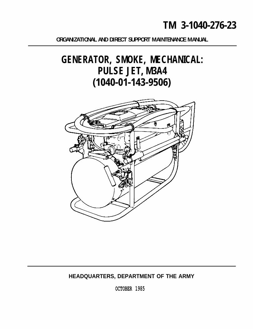
TM 3-1040-276-23ORGANIZATIONAL AND DIRECT SUPPORT MAINTENANCE MANUAL
GENERATOR, SMOKE, MECHANICAL:PULSE JET, M3A4
(1040-01-143-9506)
HEADQUARTERS, DEPARTMENT OF THE ARMY
OCTOBER 1985

WARNINGS
FIRE HAZARDFlames, hot gases, or hot fog oil may shoot out from smoke outlet nozzles up to 24 hours afteroperation. Use two people at nozzle end, one on each side, to lift and carry a hot smoke generator.
Gasoline fumes may be present even after tank has been washed and can cause an explosion andinjury to personnel. Do not use open flame torch of any kind to apply heat to fuel tank for soldering. Usea soldering iron to apply heat, but do not heat iron to point it glows or can cause a spark.
A hot engine may cause fuel or trapped gases to ignite. Wait till engine cools before attemptingprocedure. Make sure float bowl toggle valve is off before pulling fuel tube from metering jet. Use asuitable authorized container for draining fuel.
HEAT HAZARDFog oil pump may become very hot during operation. Make sure fog oil pump air motor is cool beforechecking for stuck rocker arms, pump rod assembly, or tappet valves to avoid injury.
HEALTH HAZARDGasket made of lead. Wash hands to avoid lead poisoning after handling lead gasket.
Asbestos fibers can cause cancer if inhaled. Handle asbestos gasket with care.
FIRST AIDFor first aid information, refer to FM21-11.

TM 3-1040-276-23C1
CHANGE
No. 1
HEADQUARTERSDEPARTMENT OF THE ARMY
WASHINGTON, DC, 19 June 1989
Organizational and Direct SupportMaintenance Manual
GENERATOR, SMOKE, MECHANICAL: PULSE JET, M3A4(NSN 1040-01-143-9506)
TM 3-1040-276-23, 11 October 1985, is changed as follows:
1. New or changed material is indicated by a vertical bar in the margin of the page.
2. Changes to illustrations are indicated by a pointing hand.
3. Remove old pages and insert new pages as indicated below.
Remove pages Insert pages
2-1 thru 2-142-23 and 2-242-35 thru 2-46None2-61 thru 2-66None2-67 thru 2-703-5 and 3-63-9 thru 3-143-21 and 3-223-39 thru 3-42B-3 thru B-5/(B-6 blank)D-1 thru D-3/(D-4 blank)Index 1 and Index 2
2-1 thru 2-142-23 and 2-242-35 thru 2-462-48.1/(2-48.2 blank)2-61 thru 2-662-66.1 thru 2-66.21/(2-66.22 blank)2-67 thru 2-71/(2-72 blank)3-5 and 3-63-9 thru 3-143-21 and 3-223-39/(3-40 blank)B-3 thru B-6D-1 thru D-4Index 1 and Index 2
4. File this change sheet in back of the publication for reference purposes.
By Order of the Secretary of the Army:
Official:WILLIAM J. MEEHAN
Brigadier General, United States ArmyThe Adjutant General
CARL E. VUONOGeneraI, United States Army
Chief of Staff
Distribution:To be distributed in accordance with DA Form 12-28, requirements for TM 3-1040-276-23.


TM 3-1040-276-23
TECHNICAL MANUAL HEADQUARTERSDEPARTMENT OF THE ARMY
No. 3-1040-276-23 Washington, DC, 11 October 1985
Organizational and Direct SupportMaintenance Manual
GENERATOR, SMOKE, MECHANICAL: PULSE JET, M3A4(1040-01-143-9506)
REPORTING ERRORS AND RECOMMENDING IMPROVEMENTS
You can help improve this manual. lf you find any mistakes or if you know of a way to improve theprocedures, please let us know. Mail your letter, DA Form 2028 (Recommended Changes to Publicationsand Blank Forms), or DA Form 2028-2 located in the back of this manual direct to: Commander, US ArmyArmament, Munitions, and Chemical Command, ATTN: AMSMC-MAR-T (A), Aberdeen Proving Ground,MD 21010-5423. A reply will be furnished to you.
CHAPTER 1Section ISection IISection Ill
CHAPTER 2Section I
Section IISection IllSection IVSection V
CHAPTER 3Section I
Section II
APPENDIX A
APPENDIX B
APPENDIX C
APPENDIX D
Page
HOW-TO-USE THIS MANUAL . . . . . . . . . . . . . . . . . . . . . . . . . . . . . . . . . . . . . . . . . . . iiiINTRODUCTION . . . . . . . . . . . . . . . . . . . . . . . . . . . . . . . . . . . . . . . . . . . . . . . . . . . . . . .1-1
General Information . . . . . . . . . . . . . . . . . . . . . . . . . . . . . . . . . . . . . . . . . . . . . . . . . .1-1Equipment Description and Data . . . . . . . . . . . . . . . . . . . . . . . . . . . . . . . . . . . . . . .1-1Principles of Operation . . . . . . . . . . . . . . . . . . . . . . . . . . . . . . . . . . . . . . . . . . . . . . 1-1
ORGANIZATIONAL MAINTENANCE INSTRUCTIONS . . . . . . . . . . . . . . . . . . . . . . . 2-1Repair Parts; Special Tools; Test, Measurement, and Diagnostic Equipment
(TMDE); and Support Equipment . . . . . . . . . . . . . . . . . . . . . . . . . . . . . . . . . . . . 2-1Service upon Receipt . . . . . . . . . . . . . . . . . . . . . . . . . . . . . . . . . . . . . . . . . . . . . . . . 2-1Preventive Maintenance Checks and Services (PMCS) . . . . . . . . . . . . . . . . . . . . 2-2Troubleshooting Procedures . . . . . . . . . . . . . . . . . . . . . . . . . . . . . . . . . . . . . . . . . . 2-8Organizational Maintenance Procedures . . . . . . . . . . . . . . . . . . . . . . . . . . . . . . . . 2-13
DIRECT SUPPORT MAINTENANCE INSTRUCTIONS . . . . . . . . . . . . . . . . . . . . . . 3-1Repair Parts; Special Tools; Test, Measurement, and Diagnostic Equipment
(TMDE); and Support Equipment . . . . . . . . . . . . . . . . . . . . . . . . . . . . . . . . . . . . . 3-1Direct Support Maintenance Procedures . . . . . . . . . . . . . . . . . . . . . . . . . . . . . . . . 3-1
REFERENCES . . . . . . . . . . . . . . . . . . . . . . . . . . . . . . . . . . . . . . . . . . . . . . . . . . . . . . . . A-1
MAINTENANCE ALLOCATION CHART . . . . . . . . . . . . . . . . . . . . . . . . . . . . . . . . . . . B-1
EXPENDABLE/DURABLE SUPPLIES AND MATERIALS LIST . . . . . . . . . . . . . . . . C-1
ILLUSTRATED LIST OF MANUFACTURED ITEMS . . . . . . . . . . . . . . . . . . . . . . . . . D-1
ALPHABETICAL INDEX . . . . . . . . . . . . . . . . . . . . . . . . . . . . . . . . . . . . . . . . . . . . . . . Index-1
i

TM 3-1040-276-23
HOW-TO-USE THIS MANUAL
GENERAL. When using this manual, check all warn-ings and cautions before operating the M3A4 smokegenerator and review the entire maintenance procedurebefore beginning the maintenance task. References areto pages, figures, or other publications. TM 3-1040-255-10 provides procedures for installing the M2smoke generator mount.
INDEXES. Three indexes provide quick access toparts of this manual.
a. Table of Contents. Lists in order all chaptersand their sections and appendixes. Gives page refer-ences.
b. Symptom Index. Indexes the common malfunc-tions that may be reported to you by the operator orthat you may find during maintenance.
c. Alphabetical Index. Lists page numbers foreach paragraph and appendix.
ORGANIZATIONAL MAINTENANCE INSTRUCTIONS.Chapter 2 covers the following information:
a. Repair Parts; Special Tools; Test, Measurement,and Diagnostic Equipment (TMDE); and Support Equip-ment.
b. Service Upon Receipt. Gives procedures forservicing smoke generators upon receipt.
c. Preventive Maintenance Checks and Ser-vices. Lists mandatory semiannual inspections andservices.
d. Troubleshooting Procedures. Provides the typi-cal malfunctions reported by the operator to organiza-tional maintenance. Lists the tests or inspections, andsequential steps to be taken to correct failures reportedon the generator. Refers to organizational maintenanceinstructions required to correct the problem.
e. Organization/Maintenance Procedures. Pro-vides initial setup and detailed procedures for perform-ing maintenance functions authorized by the MAC,appendix B.
DIRECT SUPPORT MAINTENANCE INSTRUCTIONS.Chapter 3 covers the following information.
a. Repair Parts; Special Tools; Test Measurement,and Diagnostic Equipment (TMDE); and Support Equip-ment.
b. Direct Support Maintenance Procedures. Pro-vides initial setup and detailed procedures for perform-ing maintenance functions authorized by the MAC,appendix B.
APPENDIXES. This appendixes covers the followinginformation.
a. Appendix A. Lists all references used.
b. Appendix B. Contains the maintenance alloca-tion chart (MAC) for the M3A4 smoke generator.
c. Appendix C. Lists expendable or durable sup-plies needed to operate and maintain the M3A4 smokegenerator.
d. Appendix D. Lists and illustrates items requiringmanufacture.
EXAMPLE. You are a Quartermaster and ChemicalEquipment Repairer, MOS 63J. You have received anM3A4 smoke generator from the operator for repair atorganizational maintenance level. The operator reportsthat the fog oil pump fails to pump fog oil. (Note: Thesame methods of finding information apply to directsupport maintenance.)
a. How do you start? Look at the table of contentsin the front of this manual. On the left side you find thelisting chapter 2, Organizational Maintenance, sectionIV, Troubleshooting Procedures, telling you to go topage 2-8.
b. What malfunction did the operator report for thegenerator turned into you for repair? If the DA Form2404 does not tell you, ask the operator to describe theproblem.
c. How do you fix a problem? Follow the step-by-step instructions in the troubleshooting table. Theinstructions under corrective action tell you whatmaintenance procedures to follow and the page num-ber. Follow the procedures until the problem is fixed orthe instructions tell you to refer the problem to directsupport maintenance for repair of the generator.
d. What supplies and equipment will you need?Go to the alphabetical index in the back of the manual.Look for the major component you are going to fix. Forexample, M4 fog oil pump maintenance instructions fororganizational maintenance refer you to page 2-61.There, under Initial Setup, you will find a list of tools,supplies, and materials you will need.
ii


TM 3-1040-276-23
FULL EXTERNAL VIEW OF M3A4 PULSE JET MECHANICAL SMOKE GENERATOR
(iii blank)/1-0

TM 3-1040-276-23
CHAPTER 1INTRODUCTION
Section I. GENERAL INFORMATION
1-1. SCOPE. a. Type of Manual. Organizational and Direct Sup-
port Maintenance Manual.
b. Model Number and Equipment Name. M3A4pulse jet mechanical smoke generator.
c. Purpose of Equipment. To generate large areasmoke screens that will reduce direct visual observa-tion and conceal troops, vehicles, or installations fromenemy view.
1-2. MAINTENANCE FORMS, RECORDS, AND REPORTS. Department of the Army forms and proce-dures used for equipment maintenance will be thoseprescribed by DA PAM 738-750, The Army Mainte-nance Management System (TAMMS), as contained inMaintenance Management Update.
1-3. DESTRUCTION OF ARMY MATERIEL TO PRE- VENT ENEMY USE. Destroy M3A4 smoke generatorcomponents by mechanical means, demolition, fire, orimproper operation as described in TM 43-0002-31.
1-4. PREPARATION FOR STORAGE OR SHIPMENT.Refer to TM 740-90-1 for administrative storageinstructions.
1-5. OFFICIAL NOMENCLATURE, NAMES, ANDDESIGNATIONS. This listing includes nomenclaturecross-references used in this manual.
Common Name
Air hoseAir pump assemblyAir release button
Engine tube assemblyFog oil exhaust hoseFog oil inlet hoseFog oil lineFuel gageFuel hoseFuel shutoff valveLock pinIgnition cableM3A4 smoke generator
Pin and chain assemblyPressurizing linePurging air lineToggle valve
Official Nomenclature
Nonmetallic hose assemblyManual inflating pumpControl valve and moisture
proof bootEngine manifoldNonmetallic hoseRubber hose assemblyTube, copper assemblyLiquid quantity indicatorNonmetallic hose assemblyPlug cockQuick release pinSpecial purpose cableGenerator, Smoke.
Mechanical: Pulse Jet,M3A4
Headed straight pinTube assemblyTube assemblyShutoff cock
1-6. REPORTING EQUIPMENT IMPROVEMENT REC-OMMENDATIONS (EIR’s). If your M3A4 smoke gener-ator needs improvement, let us know. Send us an EIR.You, the user, are the only one who can tell us whatyou don’t like about your equipment. Let us know whyyou don’t like the design or performance. Tell us why aprocedure is hard to perform. Put it on an SF 368 (Qual-ity Deficiency Report). Mail it to us at Commander, USArmy Armament, Munitions, and Chemical Command,ATTN: AMSMC-QAD (R), Rock Island, IL 61299-6000.We’ll send you a reply.
Section Il. EQUIPMENT DESCRIPTION AND DATA
1-7. EQUIPMENT DATA. See TM 3-1040-276-10.
Section Ill. PRINCIPLES OF OPERATION
1-8. PRINCIPLES OF OPERATION. The M3A4 pulse the following schematic flow diagram. Each of thejet mechanical smoke generator uses fuel (gasoline), air maintenance significant functional components of thepressure, exhaust gases, and fog oil to start, operate, M3A4 smoke generator described below is repre-generate smoke, or purge the generator as shown on sented in this diagram.
1-1

TM 3-1040-276-23
SCHEMATIC DIAGRAM OF MAINTENANCE SIGNIFICANTFUNCTIONAL COMPONENTS OF M3A4 SMOKE GENERATOR
1-2

TM 3-1040-276-23
a. Fuel Tank Assembly. Supplies fuel (by gravityflow) to carburetor reservoir of adjustable float assem-bly on engine assembly. Fuel gage indicates fuel level.
b. Engine Assembly. Gasoline-operated, pulse jet, izing line to drive M4 fog oil pump. The remaining gassingle-cycle engine that heats fog oil to generate vaporizes fog oil injected in engine tube and forces fogsmoke. Adjustable float assembly meters fuel to engine oil vapors into inner shell, through mufflers, and outhead assembly. Engine head assembly injects fuel-air smoke discharge nozzles. Once discharged, cooler airmixture into combustion chamber of engine tube condenses fog oil vapors into small droplets to formassembly. Spark igniter initially ignites fuel-air mixture. dense white smoke.Some hot exhaust gases are routed through a pressur-
1-3

TM 3-1040-276-23
c. Engine Head Assembly. Pulse-jet engine-headand adapter assembly with a metering jet, flowjector,and engine valve which is held to rear of engine head byan engine valve backstop, washer, and cap screw. Fuelflows by gravity into metering jet. Air from air accumula-tor passes over three fuel spray orifices in flowjector todraw fuel into engine head venturi. Air pressure opensengine valve as far as engine valve backstop and forcesfuel-air mixture into combustion chamber of enginetube assembly. Spark from spark igniter explodes fuel-air mixture closing engine valve and forcing burninggases through engine tube. Shock waves movingthrough engine tube away from engine valve developnegative pressure on combustion chamber side ofengine valve. This vacuum opens engine valve anddraws air into combustion chamber. As air from atmo-sphere passes over fuel spray orifices in flowjector, fuel
is drawn into air stream past engine valve. Once incombustion chamber, fuel-air mixture is ignited by hotgases in chamber and cycle begins again without aspark from spark igniter.
d. Air Pump Assembly. Hand-operated plunger-type air pump. Pressurizes air accumulator assemblywhich provides pressurized air through air line and airhose to engine head assembly.
e. Magneto-Air Pump Assembly. Hand-operatedplunger-type air pump and magnetic-electric magneto.Pump handle is connected to rack which engages mag-neto gear. Sends electric charge through ignition cableand spark igniter to start engine. Pumps air through airpump line to purge hot exhaust gases from engine tubeassembly after shut-down of generator.
1-4

TM 3-1040-276-23
f. M4 Fog Oil Pump. Driven by an air motor. rod. Oil pump draws fog oil through fog oil inlet hoseEngine exhaust gases enter pressurizing line through inserted in fog oil drum. Oil pump pumps fog oil into fogair check valve on M4 fog oil pump air motor. Pressure oil line leading to engine assembly. Excess oil lubricatesfrom engine exhaust gases drives the air motor piston air motor and is returned to fog oil drum through fog oilwhich is connected to the oil pump piston by a piston exhaust hose.
1-5/(1-6 blank)


.TM 3-1040-276-23
CHAPTER 2ORGANIZATIONAL MAINTENANCE INSTRUCTIONS
Section I. REPAIR PARTS; SPECIAL TOOLS; TEST, MEASUREMENT,AND DIAGNOSTIC EQUIPMENT (TMDE); AND SUPPORT EQUIPMENT
2-1. COMMON TOOLS AND EQUIPMENT. For au- 2-2. SPECIAL TOOLS, TMDE, AND SUPPORTthorized common tools and equipment, refer to the EQUIPMENT. Refer to the Maintenance AllocationModified Table of Organization and Equipment (MTOE) Chart (app B) for support equipment.assigned to your unit.
2-3. REPAIR PARTS. Repair parts are listed and illus-trated in TM 3-1040-276-23P.
Section Il. SERVICE UPON RECEIPT
SERVICE UPON RECEIPT - SMOKE GENERATOR
LOCATION
1
2
Shipping Container
Smoke Generator
ITEM
Smoke generator
a. Components
b. Smoke generator
ACTION
Unpack.
a.
b.
c.
Inspect the equipment for dam-age incurred during shipment. Ifthe equipment has been dam-aged, report the damage on SF364, Report of Discrepancy.(ROD).
Check the equipment againstthe packing slip to see if theshipment is complete. Reportall discrepancies in accordancewith the instructions of DAPAM 738-750.
Check to see whether theequipment has been modified.
Perform operator and monthlyorganizational PMCS and operatesmoke generator.
REMARKS
Refer to DA PAM 310-1.
TM 3-1040-276-10
Change 1 2-1

TM 3-1040-276-23
Section Ill. PREVENTIVE MAINTENANCE CHECKS AND SERVICES (PMCS)
2-4. ORGANIZATIONAL PREVENTIVE MAINTE-NANCE CHECKS AND SERVICES.
a. Purpose. The purpose of organizational PMCSis to systematically and periodically inspect and servicethe M3A4 smoke generator:
(1) To insure that the equipment is ready foroperation at all times.
(2) To perform those PMCS procedures thatare beyond the capability of the operator/crew.
(3) To discover and correct defects before theyresult in serious damage or failure requiring time-con-suming repairs or replacement.
b. Use.
(1) Schedule each of your unit’s smoke genera-tors for organizational PMCS at specified intervals.
(2) Use the schedule below as a check list eachtime you perform the PMCS to make sure that youperform all required procedures.
(3) Report and record all deficiencies and short-comings, together with corrective actions taken, on DAForm 2404, Equipment Inspection and MaintenanceWorksheet.
(4) Make sure that you record the serial num-bers for both the smoke generator and its M4 fog oilpump assembly.
(5) Because it takes two persons to lift andcarry the smoke generator and the operator knows his/
her smoke generator best, use the assigned operator, ifavailable, to assist in performing the organizationalPMCS.
c. Explanation of Columns on the PMCS Schedule.
(1) Item number column. Checks and servicesare numbered in order of performance. Use this columnas a source of item numbers for the TM NumberColumn on DA Form 2404, Equipment Inspection andMaintenance Worksheet, in recording results of PMCS.
(2) Interval column designates the interval atwhich the procedures are to be performed. M meansmonthly. S means semiannually. The dots indicate theitems to be inspected and the procedure to be per-formed.
(3) Item to be inspected column. The itemslisted in this column are divided into groups indicatingthe portion of the equipment of which they are part. Thecommon name or official nomenclature as shown onthe maintenance allocation chart (app B) is used for thispurpose.
(4) Procedures column. This column brieflydescribes the procedure for performing the check orservice. Whenever replacement or repair is recom-mended, reference is made to page number for theapplicable maintenance instruction.
2-2 Change 1

ItemNo.
1
2
TM 3-1040-276-23
ORGANIZATIONAL PREVENTIVE MAINTENANCE CHECKS AND SERVICES SCHEDULE
Interval
M S
M - MONTHLY S - SEMIANNUALLY
ItemTo Be
Inspected
M3A4 smokegenerator
Air pumpassembly
Procedures
Perform operator PMCS (TM 3-1040-276-10). Tighten all loose screws andnuts. Perform authorized organizational maintenance as required. Evacu-ate to direct support maintenance as required. Make sure instruction plate(caution plate) is legible and not torn. Replace if necessary (p 2-14).
a.
b.
c.
Open the front cover. Straighten and remove two cotter pins (1),extract lock pin (2) and pull air pump handle (3) out to remove air pumpcomponents from air pump tube (4).
Clean parts with dry cleaning solvent (item 4, app C) and dry with rag(item 6, app C).
Check for broken or missing parts. Check for bent or missingwasher (5), cut, torn, or frayed felt washer (6). Check for deformed orfrayed sleeve nut (7). Check for bent air pump rod (8) and bent orpunctured air pump tube (4). Replace missing or damaged parts(p 2-67).
Change 1 2-3

TM 3-1040-276-23
ItemNo.
Interval
M S
ORGANIZATIONAL PREVENTIVE MAINTENANCE CHECKS AND SERVICES SCHEDULE (CONT)
2
Change 1
M - MONTHLY S - SEMIANNUALLY
ItemTo Be
Inspected
Air pumpassembly(cont)
Procedures
d.
e.
f.
g.
h.
Lubricate sleeve nut (7), inside of air pump tube (4), and felt washer (6)with lubricating oil (item 6, app C).
Press air release button (9) to release pressure from accumulatorassembly before inserting air pump piston (10).
Insert air pump piston (10) end into air pump tube (4) and press pumprod bushing (11) into tube while alining two holes in bushing with twoholes in tube. Insert two cotter pins (1) through two holes in air pumptube and pump rod bushing. Bend ends of cotter pins.
Perform operator’s PMCS on air pump assembly (TM 3-1040-276-10)and troubleshoot if necessary (p 2-67).
Insert lock pin (2) into air pump handle (3).
2-4

ItemNo.
3
TM 3-1040-276-23
ORGANIZATIONAL PREVENTIVE MAINTENANCE CHECKS AND SERVICES SCHEDULE (CONT)
Interval
M S
M - MONTHLY S - SEMIANNUALLY
ItemTo Be
Inspected
Magneto airpumpassembly
Procedures
a.
b.
c.
d.
Unwrap fog oil inlet and exhaust hoses.
Disconnect ignition cable (1) from ignition magneto outlet (2).
Remove cap screw (3) with washer from bracket (4), clamp (5), andignition magneto assembly (6) housing.
Remove cap screw (7), flat washer (8), nut (9), and Iockwasher (10),from ignition magneto assembly (6) housing and clamp (5). Lift magnetoassembly (6) from clamp (5).
Change 1 2-5

TM 3-1040-276-23
ItemNo.
ORGANIZATIONAL PREVENTIVE MAINTENANCE CHECKS AND SERVICES SCHEDULE (CONT)
M - MONTHLY S - SEMIANNUALLY
Interval
M S
ItemTo Be
Inspected
3 Magneto airpumpassembly(cont)
Procedures
e.
f.
g.h.
i.
j.k.
l.
Remove cap screw (11) and washer (12) from frame (13) and clamp (5).
Pull air pump handle (14) and remove clamp (5) with assembledfrom magneto air pump tube (15).
items
Clean dirty parts with dry cleaning solvent (item 4, app C).
Check plunger (16) for cuts, brittleness, or deterioration.
Check for bent rack (17) and broken rack teeth.
Check for broken teeth on gear (18) and check if gear turns easily.
Disassemble, clean, inspect, repair, replace, and reassemble parts asrequired (p 2-51).
Fill grease cup (19) with aircraft grease (item 5, app C), and lubricateinside of magneto air pump tube and plunger (16) with lubricating oil(item 6, app C).
CAUTIONWhen inserting plunger (16) intomagneto air pump tube (15),carefully guide plunger pastedges of groove opening in tube.Forcing plunger against theedges will cut or tearthe plunger.
2-6 Change 1

ItemNo.
3
TM 3-1040-276-23
ORGANIZATIONAL PREVENTIVE MAINTENANCE CHECKS AND SERVICES SCHEDULE (CONT)
M - MONTHLY S - SEMIANNUALLY
Interval
M S
ItemTo Be
inspected
Magneto airpumpassembly(cont)
Procedures
m. While holding air pump handle (14), insert plunger (16) into air pumptube (15) and push handle and clamp until clamp mates with tube andslides onto bracket (4). Install cap screw (11) and washer (12) throughframe (13) and into clamp (5).
n.
o.
p.
q.
NOTEAline teeth on rack with ignition magneto gear. Operatehandle to make sure teeth are alined.
Position ignition magneto assembly (6) housing onto clamp (5) andinstall cap screw (3) with washer.
Install cap screw (7), flat washer (8), nut (9), and Iockwasher (10) intoignition magneto assembly (6) housing and clamp (5).
Connect ignition cable (1) to ignition magneto assembly outlet (2).
Operate smoke generator (TM 3-1040-276-10).
Change 1 2-7

TM 3-1040-276-23
Section IV. TROUBLESHOOTING PROCEDURES
2-5. ORGANIZATIONAL MAINTENANCE TROUBLE-SHOOTING PROCEDURES.
a. The table (p 2-8) lists the common malfunctionsthat may be reported to you by the operator or you mayfind during maintenance of the M3A4 smoke generatoror its components. Perform the tests/inspections andcorrective actions in the order listed.
b. This manual cannot list all malfunctions that mayoccur, nor all tests or inspections and corrective
actions. If a malfunction is not listed or is not correctedby listed corrective actions, notify your supervisor.
c. Before you use the troubleshooting table, checkwith the operator to determine if all operator trou-bleshooting procedures for the reported malfunctionhave been followed. If in doubt, repeat the operatortroubleshooting procedures before proceeding andafter replacing faulty components.
SYMPTOM INDEX
TroubleshootingProcedure
Page
AIR PRESSURE GAGERegisters low pressure . . . . . . . . . . . . . . . . . . . . . . . . . . . . . . . . . . . . . . . . . . . . . . . . . . . . . . . . . . . . . . . . 2-8
AIR PUMP ASSEMBLY/AIR ACCUMULATOR ASSEMBLYGives weak or no starting air blast . . . . . . . . . . . . . . . . . . . . . . . . . . . . . . . . . . . . . . . . . . . . . . . . . . . . . . . 2-9
FOG OIL EXHAUST HOSEGushes fog oil . . . . . . . . . . . . . . . . . . . . . . . . . . . . . . . . . . . . . . . . . . . . . . . . . . . . . . . . . . . . . . . . . . . . . . . . 2-10
FOG OIL PUMPFails to pump fog oil . . . . . . . . . . . . . . . . . . . . . . . . . . . . . . . . . . . . . . . . . . . . . . . . . . . . . . . . . . . . . . . . . . . 2-11
IGNITION CABLE/MAGNETOGives no spark or weak spark . . . . . . . . . . . . . . . . . . . . . . . . . . . . . . . . . . . . . . . . . . . . . . . . . . . . . . . . . . 2-9
MAGNETO AIR PUMP ASSEMBLYFails to purge smoke/exhaust gases from engine . . . . . . . . . . . . . . . . . . . . . . . . . . . . . . . . . . . . . . . . . 2-12
TROUBLESHOOTING
MALFUNCTIONTEST OR INSPECTION
CORRECTIVE ACTION
1. AIR PRESSURE GAGE REGISTERS LOW PRESSURE.
Step 1. Check air accumulator and air pump assembly for loose fittings and connections and forcracks in air pump assembly and air accumulator.
Tighten loose fittings and connections and replace cracked air pump assembly (p 2-32)and air accumulator (p 2-15).
Step 2. Check air accumulator check valve.
Replace faulty air accumulator check valve (p 2-19).
2-8

TM 3-1040-276-23
TROUBLESHOOTING (CONT)
MALFUNCTIONTEST OR INSPECTION
CORRECTIVE ACTION
Step 3. Check air pump assembly check valve and filter plug.
Replace faulty check valve and filter plug (p 2-31).
Step 4. Check air pressure gage.
Replace faulty air pressure gage (p 2-20).
2. AIR PUMP ASSEMBLY/AIR ACCUMULATOR ASSEMBLY GIVES WEAK OR NO STARTING AIR BLAST.
Step 1. Air hose split, cut, or doesn’t fit.
Replace air hose (p 2-42).
Step 2. Control valve stuck.
Replace control valve (p 2-20).
3. IGNITION CABLE/MAGNETO GIVES NO SPARK OR WEAK SPARK.
CAUTIONHandle ignition cable with care. Rough handling cracks insulator. When you pump magneto air pumphandle, stop short in both directions. Use short strokes about 8 inches long. Rough handling cracksmagneto air pump clamp.
Step 1. Ignition cable contacts (1) corroded or insulator (2) cracked.
Clean cable contacts. Repair damaged cable (p 2-71).
Change 1 2-9

TM 3-1040-276-23
TROUBLESHOOTING (CONT)
MALFUNCTIONTEST OR INSPECTION
CORRECTIVE ACTION
Step 2.
Step 3.
Step 4.
Step 5.
Step 6.
Step 7.
Ignition terminal sleeve contact corroded or insulatorchipped or cracked.
Replace ignition terminal sleeve (p 2-55).
Coil clip (4) missing or broken.
Replace coil clip (4) (p 2-55).
Capacitor cracked or has broken lead.
Replace capacitor (p 2-55).
Contact set points pitted or corroded. Separatepoints by inserting screwdriver blade and checkpoints.
Replace contact set (p 2-55).
Contact set point gap may need adjusting. Rotate cam so that breaker arm of contact set sitson high center. Then check gap between points with 0.015-inch feeler gage. Feeler shouldslide in between points with little resistance or play.
Adjust contact set point gap (p 2-55).
Coil has cracked insulator or broken leads.
Replace ignition magneto (p 2-51).
Step 8. Rotor-coil induction producing weak electrical charge.
Replace ignition magneto (p 2-51).
4. FOG OIL EXHAUST HOSE GUSHES FOG OIL.
Step 1. Test for faulty air check valve assembly disc valve. Remove air check valve assembly (p 2-61).Shake valve body and listen for rattle.
If disc valve doesn’t rattle (won’t open or close), repair air check valve assembly(p 2-66.21).
Step 2. Fog oil pump air motor leaks.Remove M4 fog oil pump (p 2-26) and repair (2-66.7).
Step 3. Pressurizing line clogged.
Report on DA Form 2404 to your supervisor.
2-10 Change 1

TM 3-1040-276-23
TROUBLESHOOTING (CONT)
MALFUNCTIONTEST OR INSPECTION
CORRECTIVE ACTION
5. FOG OIL PUMP FAILS TO PUMP FOG OIL.
Step 1. Fog oil inlet hose has loose connections, breaks, or missing, clogged, or torn fog oil strainer.
Repair fog oil inlet hose (p 2-60).
WARNINGFog oil pump may become very hot during operation. Make sure fog oil pump air motor is cool beforechecking for stuck rocker arms, pump rod assembly, or tappet valves to avoid injury.
Step 2. Rocker arms, pump rod assembly, or tappet valves are stuck.
Remove M4 fog oil pump (p 2-26) and repair (p 2-66.7).
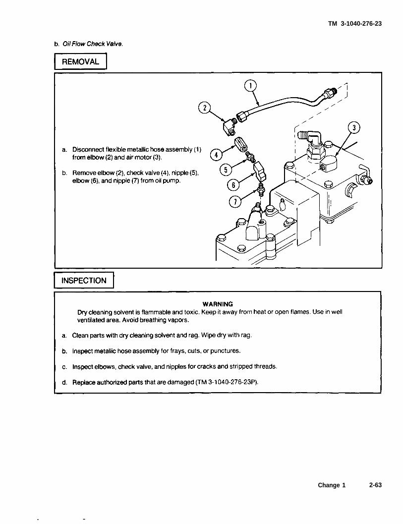
Step 3. Oil check valve stuck.
Replace check valve (p 2-63).
Step 4. Test for faulty air check valve assembly disc valve (malfunction 4, step 1).
If valve won’t open or close, repair (p 2-66.21).
Step 5. Air motor overloaded with oil.
Press boots on safety release valves and drain oil (p 2-27).
Step 6. Fog oil pump internal moving parts stuck or binding.
Remove fog oil pump (p 2-26) and repair (p 2-66.7).
Step 7. Fog oil line clogged or oil metering globe valve stuck.
Report on DA Form 2404 to your supervisor.
Step 8. Engine gases leaking past engine head gasket.
Check for carbon deposits on gasket. Replace gasket if necessary (p 2-48.1).
Change 1 2-11

TM 3-1040-276-23
TROUBLESHOOTING (CONT)
MALFUNCTIONTEST OR INSPECTION
CORRECTIVE ACTION
6. MAGNETO AIR PUMP ASSEMBLY FAILS TO PURGE SMOKE/EXHAUST GASES FROM ENGINE.
WARNINGA hot engine may cause fuel or trapped gases to ignite. Wait till engine cools before attempting thisprocedure. Make sure float bowl toggle valve is off before pulling fuel tube from metering jet. Use asuitable authorized container for draining fuel.
Step 1. Test for faulty magneto-air check valve.
a.
b.
c.
d.
e.
f.
Pull fuel tube (1) from metering jet (2) and drain fuel into container.
Unscrew air pump hose (3) from flowjector (4). Remove engine head assembly (5) fromengine tube (6).
Disconnect ignition cable (7) from spark igniter (8).
Place hand in engine tube combustion chamber, pump magneto-air pump handle (9), andcheck for purging air blast from pressurizing line boss (10).
Replace magneto air pump check valve (p 2-22).
Repeat step 1d.
If no purging air blast from pressurizing line boss, go to step 2.
Assemble parts in reverse order indicated on illustration.
Step 2. Purging air line tube punctured or cracked.
Report on DA Form 2404 to your supervisor.
2-12 Change 1

p 2-8
Section V.
2-6. INTRODUCTION.
TM 3-1040-276-23
ORGANIZATIONAL MAINTENANCE PROCEDURES
to 24 hours after operation. Use two peo-
a. This section contains maintenance procedures ple at nozzle end, one on each side, to lift
which are the responsibility of the organizational main- and carry a hot smoke generator.
tenance technician as authorized by the maintenanceallocation chart (MAC) (app B) and source, mainte- b. Disassemble the smoke generator only as
nance, and recoverability (SMR) coded items in the needed for repair. One quartermaster and chemical
repair parts and special tools list (RPSTL) equipment repairer MOS 63J can do each task. How-
(TM 3-1040-276-23P). ever, it takes two people to lift and carry the smokegenerator. No special environmental conditions are
WARNING listed because none are required.
Flames, hot gases, or hot fog oil mayshoot out from smoke outlet nozzles up
2-7. SMOKE GENERATOR.
Change 1 2-13

TM 3-1040-276-23
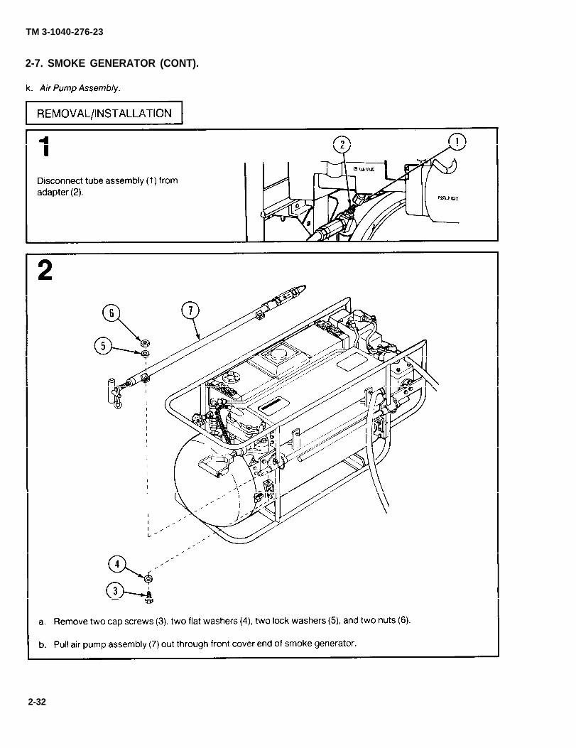
2-7. SMOKE GENERATOR (CONT).
2-14

TM 3-1040-276-23
2-15

TM 3-1040-276-23
2-7. SMOKE GENERATOR (CONT).
2-16

TM 3-1040-276-23
2-17

TM 3-1040-276-23
2-7. SMOKE GENERATOR (CONT).
2-18

p 2-15
p 2-17
TM 3-1040-276-23
2-19

p 2-15
p 2-25
TM 3-1040-276-23
2-7. SMOKE GENERATOR (CONT).
2-20

p 2-17
TM 3-1040-276-23
2-21

p 2-15
p 2-17
TM 3-1040-276-23
2-7. SMOKE GENERATOR (CONT).
2-22

p 2-15
TM 3-1040-276-23
2-23

p 2-17
TM 3-1040-276-23
2-7. SMOKE GENERATOR (CONT).
2-24 Change 1

fig D-1p 2-60
TM 3-1040-276-23
2-25

TM 3-1040-276-23
2-7. SMOKE GENERATOR (CONT).
2-26

TM 3-1040-276-23
2-27

TM 3-1040-276-23
2-7. SMOKE GENERATOR (CONT).
2-28

TM 3-1040-276-23
2-29

TM 3-1040-276-23
2-7. SMOKE GENERATOR (CONT).
2-30

TM 3-1040-276-23
2-31
TM 3-1040-276-23
2-7. SMOKE GENERATOR (CONT).
2-32

TM 3-1040-276-23
2-33

TM 3-1040-276-23
2-7. SMOKE GENERATOR (CONT).
2-34

TM 3-1040-276-23
Change 1 2-35

TM 3-1040-276-23
2-7. SMOKE GENERATOR (CONT).
2-36 Change 1

TM 3-1040-276-23
Change 1 2-37

TM 3-1040-276-23
2-7. SMOKE GENERATOR (CONT).
2-38 Change 1

TM 3-1040-276-23
Change 1 2-39

p 2-51 p 2-22
TM 3-1040-276-23
2-7. SMOKE GENERATOR (CONT).
2-40 Change 1

fig D-2
TM 3-1040-276-23
2-8. ENGINE ASSEMBLY.
2-41

fig D-2
TM 3-1040-276-23
2-8. ENGINE ASSEMBLY (CONT).
2-42 Change 1

TM 3-1040-276-23
2-9. ADJUSTABLE FLOAT ASSEMBLY.
Change 1 2-43

TM 3-1040-276-23
2-9. ADJUSTABLE FLOAT ASSEMBLY (CONT).
2-44 Change 1

TM 3-1040-276-23
Change 1 2-45

TM 3-1040-276-23
2-9. ADJUSTABLE FLOAT ASSEMBLY (CONT).
2-46 Change 1

TM 3-1040-276-23
2-10. ENGINE HEAD ASSEMBLY.
2-47

TM 3-1040-276-23
2-10. ENGINE HEAD ASSEMBLY (CONT).
2-48

TM 3-1040-276-23
2-10.1. ENGINE TUBE ASSEMBLY.
Change 1 2-48.1/(2-48.2 blank)

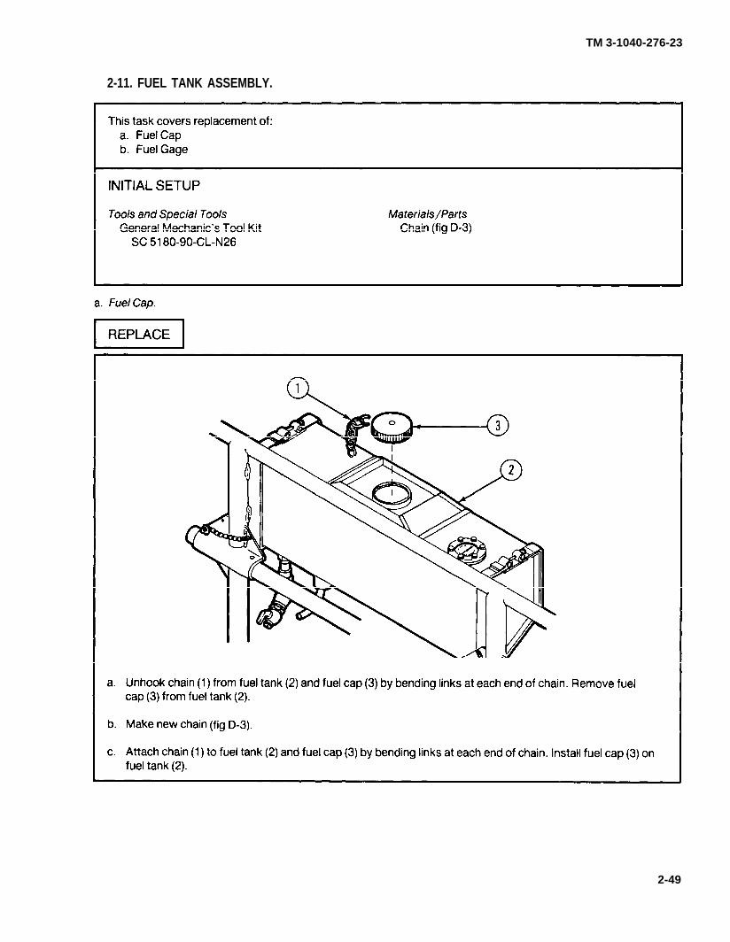
fig D-3
fig D-3
TM 3-1040-276-23
2-11. FUEL TANK ASSEMBLY.
2-49

TM 3-1040-276-23
2-11. FUEL TANK ASSEMBLY (CONT).
2-50

p 2-23
TM 3-1040-276-23
2-12. MAGNETO AIR PUMP ASSEMBLY.
2-51

TM 3-1040-276-23
2-12. MAGNETO AIR PUMP ASSEMBLY (CONT).
2-52

TM 3-1040-276-23
2-53

p 2-23
TM 3-1040-276-23
2-12. MAGNETO AIR PUMP ASSEMBLY (CONT).
2-54

p 2-51
TM 3-1040-276-23
2-13. IGNITION MAGNETO ASSEMBLY.
2-55

TM 3-1040-276-23
2-13. IGNITION MAGNETO ASSEMBLY (CONT).
2-56

TM 3-1040-276-23
2-57

TM 3-1040-276-23
2-13. IGNITION MAGNETO ASSEMBLY (CONT).
2-58

TM 3-1040-276-23
2-59

p 2-25
fig D-4
fig D-4
TM 3-1040-276-23
2-14. FOG OIL INLET HOSE ASSEMBLY.
2-60

TM 3-1040-276-23
2-15. M4 FOG OIL PUMP - EXTERNAL FlTTlNGS.
Change 1 2-61

p 2-66.21
TM 3-1040-276-23
2-15. M4 FOG OIL PUMP - EXTERNAL FlTTlNGS (CONT).
2-62
TM 3-1040-276-23
Change 1 2-63
. —

TM 3-1040-276-23
2-15. M4 FOG OIL PUMP - EXTERNAL FlTTlNGS (CONT).
2-64

TM 3-1040-276-23
Change 1 2-65

p 2-25
p 2-25
TM 3-1040-276-23
2-15. M4 FOG OIL PUMP - EXTERNAL FlTTlNGS (CONT).
2-66 Change 1

TM 3-1040-276-23
Change 1 2-66.1

p 2-25
p 2-25
TM 3-1040-276-23
2-15. M4 FOG OIL PUMP - EXTERNAL FlTTINGS (CONT).
2-66.2 Change 1

TM 3-1040-276-23
Change 1 2-66.3

TM 3-1040-276-23
2-15. M4 FOG OIL PUMP - EXTERNAL FITTINGS (CONT).
2-66.4 Change 1

p 2-26
p 2-63
TM 3-1040-276-23
2-16. M4 FOG OIL PUMP - AIR MOTOR AND HYDRAULIC PISTONS.
Change 1 2-66.5

TM 3-1040-276-23
2-16. M4 FOG OIL PUMP - AIR MOTOR AND HYDRAULIC PISTONS (CONT).
2-66.6 Change 1

TM 3-1040-276-23
Change 1 2-66.7

TM 3-1040-276-23
2-16. M4 FOG OIL PUMP - AIR MOTOR AND HYDRAULIC PISTONS (CONT).
2-66.8 Change 1

TM 3-1040-276-23
Change 1 2-66.9

p 2-66.17
TM 3-1040-276-23
2-16. M4 FOG OIL PUMP - AIR MOTOR AND HYDRAULIC PISTONS (CONT).
2-66.10 Change 1

TM 3-1040-276-23
Change 1 2-66.11

TM 3-1040-276-23
2-16. M4 FOG OIL PUMP - AIR MOTOR AND HYDRAULIC PISTONS (CONT).
2-66.12 Change 1

p 2-64
TM 3-1040-276-23
Change 1 2-66.13

p 2-63
TM 3-1040-276-23
2-17. M4 FOG OIL PUMP - PORT PLATE AND SEPARATOR ASSEMBLIES.
2-66.14

p 2-66.21 p 2-66.20
p 2-64
TM 3-1040-276-23
Change 1 2-66.15

TM 3-1040-276-23
2-18. M4 FOG OIL PUMP - ADJUSTMENT.
2-66.16 Change 1

TM 3-1040-276-23
Change 1 2-66.17
TM 3-1040-276-23
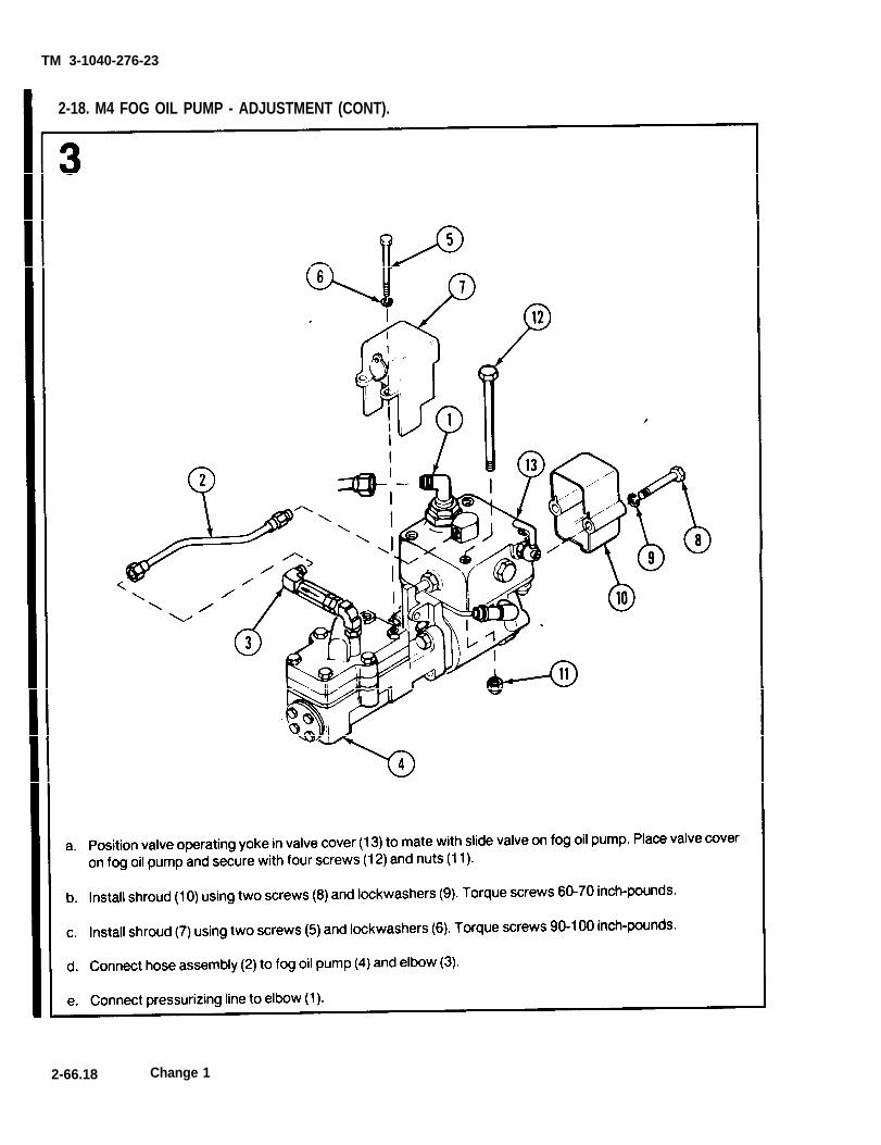
2-18. M4 FOG OIL PUMP - ADJUSTMENT (CONT).
2-66.18 Change 1

p 2-61
TM 3-1040-276-23
2-19. AIR CHECK VALVE ASSEMBLY.
Change 1 2-66.19

p 2-66.16
TM 3-1040-276-23
2-20. OIL DISCHARGE SEPARATOR ASSEMBLY.
2-66.20 Change 1

p 2-66.16
TM 3-1040-276-23
2-21. OIL PORT PLATE ASSEMBLY.
Change 1 2-66.21/(2-66.22 blank)


p 2-32
TM 3-1040-276-23
2-22. AIR PUMP ASSEMBLY.
Change 1 2-67
TM 3-1040-276-23
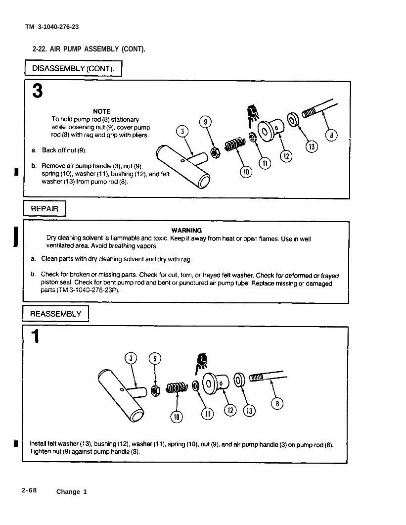
2-22. AIR PUMP ASSEMBLY (CONT).
2-68 Change 1

TM 3-1040-276-23
2-69

fig D-5
fig D-5
TM 3-1040-276-23
2-23. FRAME ASSEMBLY.
2-70 Change 1

p 2-24
fig D-8 fig D-9
TM 3-1040-276-23
2-24. IGNITION CABLE ASSEMBLY.
Change 1 2-71/(2-72 blank)

TM 3-1040-276-23
CHAPTER 3
DIRECT SUPPORT MAINTENANCE INSTRUCTIONS
Section I. REPAIR PARTS; SPECIAL TOOLS; TEST, MEASUREMENT,AND DIAGNOSTIC EQUIPMENT (TMDE); AND SUPPORT EQUIPMENT
3-1. COMMON TOOLS AND EQUIPMENT. For autho- 3-2. SPECIAL TOOLS, TMDE, AND SUPPORTrized common tools and equipment, refer to the Modi- EQUIPMENT. Refer to Maintenance Allocation Chartfied Table of Organization and Equipment (MTOE) (app B) for support equipment.assigned to your unit.
3-3. REPAIR PARTS. Repair parts are listed and illus-trated in TM 3-1040-276-23P.
Section Il. DIRECT SUPPORT MAINTENANCE PROCEDURES
3-4. INTRODUCTION.
a. This section contains maintenance procedureswhich are the responsibility of the direct supportmaintenance technician as authorized by the mainte-nance allocation chart (MAC) (app B) and source,maintenance, and recoverability (SMR) coded items inthe repair parts and special tools list (RPSTL)(TM 3-1040-276-23P).
WARNINGFlames, hot gases, or hot fog oil mayshoot out from smoke outlet nozzles up
to 24 hours after operation. Use two peo-ple at nozzle end, one on each side, to liftand carry a hot smoke generator.
b. One quartermaster and chemical equipmentrepairer (MOS 63J) can do most tasks alone. However,it takes two people to lift and carry the smoke genera-tor, engine assembly, or frame assembly. A welder isalso needed, to weld the frame. No special environmen-tal conditions are listed because none are required.
3-1

TM 3-1040-276-23
3-5. M3A4 SMOKE GENERATOR.
3-2

p 2-15
p 2-17
TM 3-1040-276-23
3-3

p 2-17 p 3-2
p 3-3 p 2-37
p 3-3p 2-37
p 3-2 p 2-16
TM 3-1040-276-23
3-5. M3A4 SMOKE GENERATOR (CONT).
3-4

TM 3-1040-276-23
Change 1 3 -5
p 3-2
p 2-15
p 2-23
p 2-20
p 2-32
TM 3-1040-276-23
3-5. M3A4 SMOKE GENERATOR (CONT).
3-6

TM 3-1040-276-23
3-7

TM 3-1040-276-23
3-5. M34A4 SMOKE GENERATOR (CONT).
3-8

TM 3-1040-276-23
3-9

p 2-34
p 2-21
p 2-23
p 2-17
p 2-23
p 3-2
TM 3-1040-276-23
3-5. M3A4 SMOKE GENERATOR (CONT).
3-10 Change 1

p 2-15
p 2-23
p 2-25
p 2-32
p 2-26
p 3-5
p 3-4
TM 3-1040-276-23
3-11

fig D-6
TM 3-1040-276-23
3-6. ENGINE ASSEMBLY.
3-12 Change 1

TM 3-1040-276-23
Change 1 3-13

p 3-13
p 3-12
p 3-5
TM 3-1040-276-23
3-6. ENGINE ASSEMBLY (CONT).
3-14 Change 1

TM 3-1040-276-23
3-15

TM 3-1040-276-23
3-6. ENGINE ASSEMBLY (CONT).
3-16
TM 3-1040-276-23
3-17

fig D-6
TM 3-1040-276-23
3-6. ENGINE ASSEMBLY (CONT).
3-18

TM 3-1040-276-23
3-19

TM 3-1040-276-23
3-6. ENGINE ASSEMBLY (CONT).
3-20

TM 3-1040-276-23
3-21

p 3-13
p 3-12
p 3-12
p 3-5
TM 3-1040-276-23
3-6. ENGINE ASSEMBLY (CONT).
3-7. FRONT COVER ASSEMBLY AND FRONT COVER BAFFLE.
3-22 Change 1
TM 3-1040-276-23
3-23

TM 3-1040-276-23
3-7. FRONT COVER ASSEMBLY AND FRONT COVER BAFFLE (CONT).
3-24

p 3-12
p 2-43
TM 3-1040-276-23
3-8. ADJUSTABLE FLOAT ASSEMBLY.
3-25

TM 3-1040-276-23
3-8. ADJUSTABLE FLOAT ASSEMBLY (CONT).
3-26

TM 3-1040-276-23
3-27

p 2-43
TM 3-1040-276-23
3-8. ADJUSTABLE FLOAT ASSEMBLY (CONT).
3-9. CARBURETOR RESERVOIR.
3-28

TM 3-1040-276-23
3-29
TM 3-1040-276-23
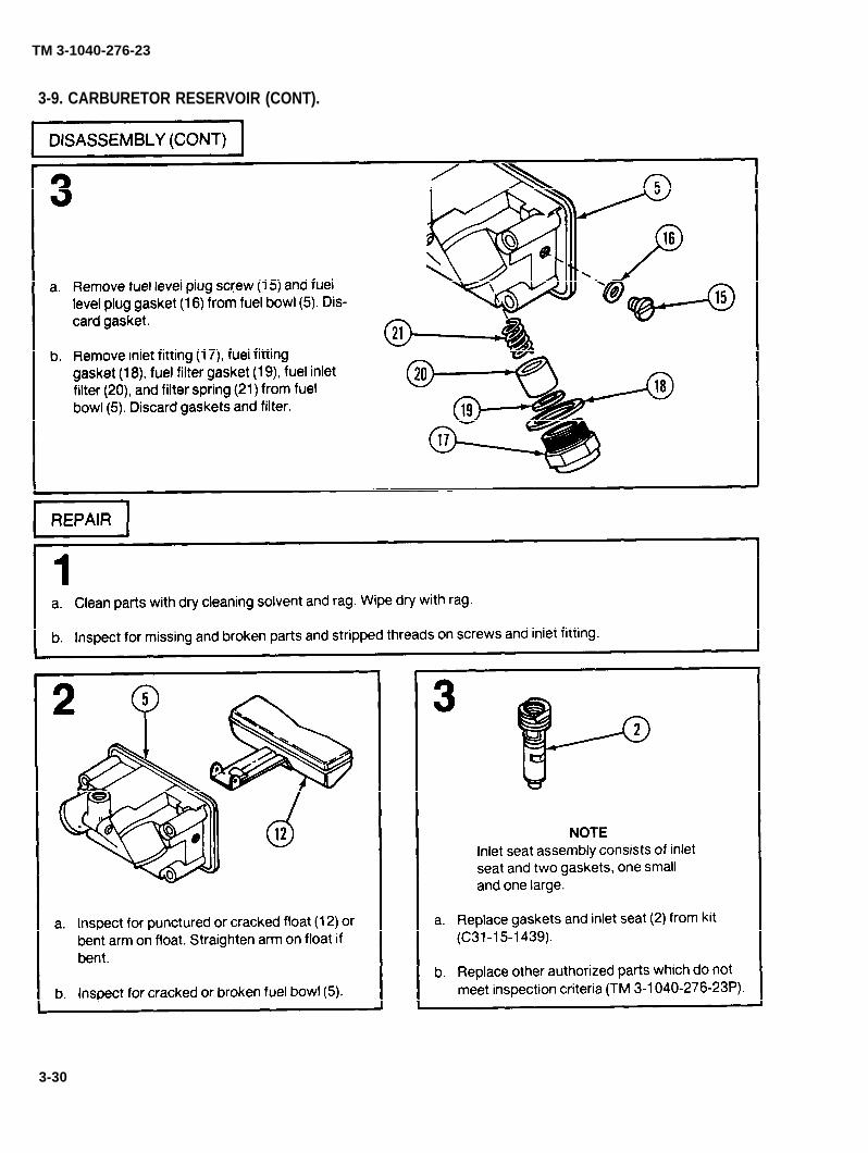
3-9. CARBURETOR RESERVOIR (CONT).
3-30

TM 3-1040-276-23
3-31

p 2-46
TM 3-1040-276-23
3-9. CARBURETOR RESERVOIR (CONT).
3-32

p 3-5
TM 3-1040-276-23
3-10. ENGINE TUBE ASSEMBLY.
3-33

TM 3-1040-276-23
3-10. ENGINE TUBE ASSEMBLY (CONT).
3-34
p 3-4
p 2-49
TM 3-1040-276-23
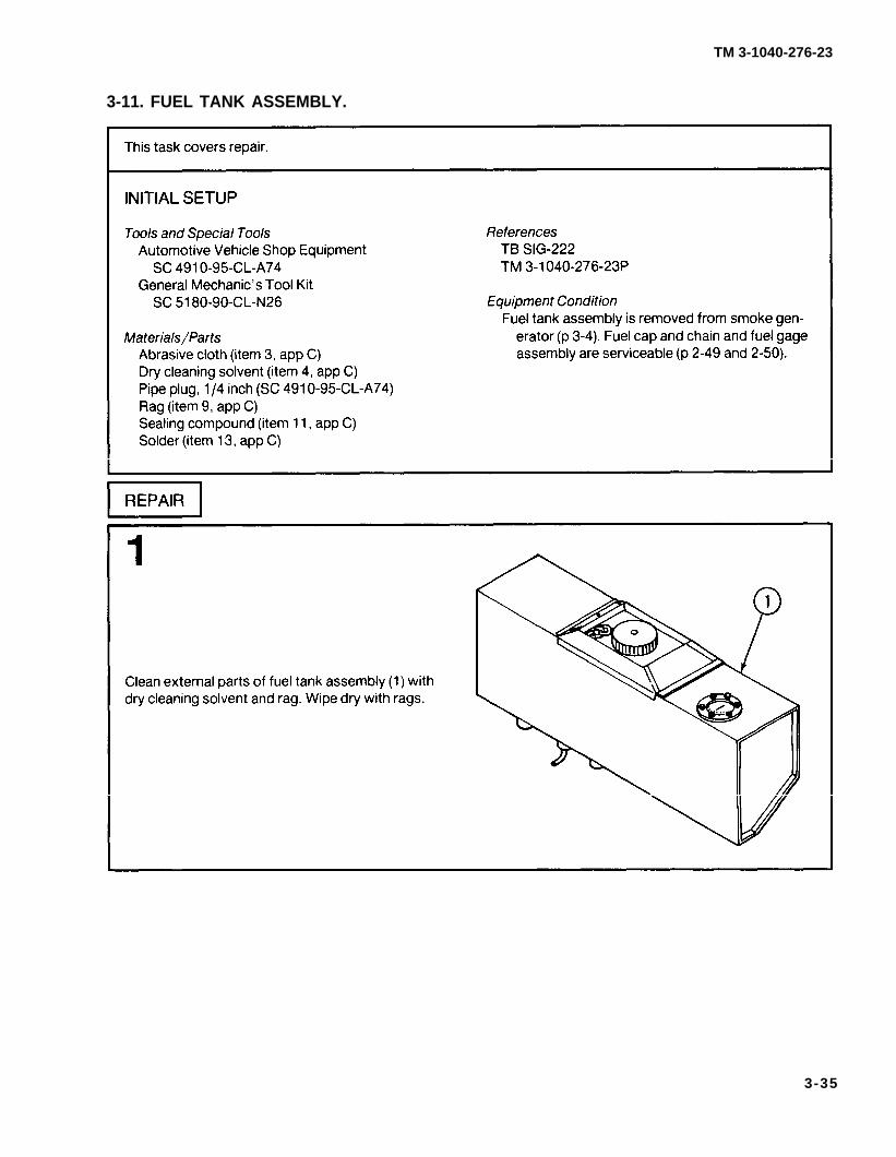
3-11. FUEL TANK ASSEMBLY.
3-35

TM 3-1040-276-23
3-11. FUEL TANK ASSEMBLY (CONT).
3-36
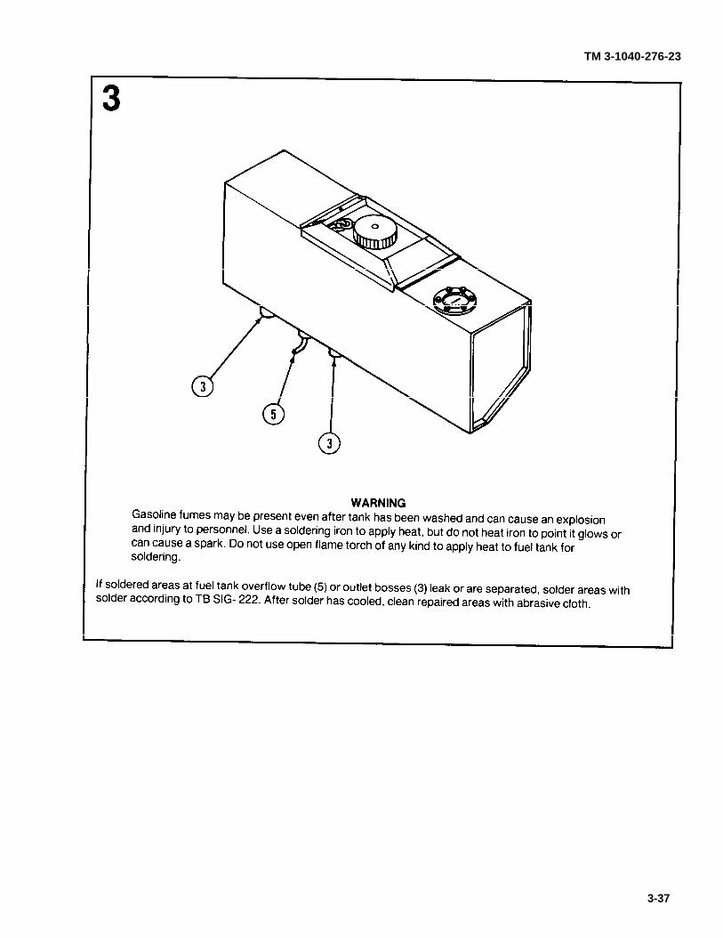
TM 3-1040-276-23
3-37

p 2-15
TM 3-1040-276-23
3-12. TOOL BOX ASSEMBLY.
3-38

TM 3-1040-276-23
Change 1 3-39/(3-40 blank)


TM 3-1040-276-23
3-41

TM 3-1040-276-23
3-13. M4 FOG OIL PUMP (CONT).
I
3-42

p 3-11
fig D-7
TM 3-1040-276-23
3-14. FRAME ASSEMBLY.
3-43

fig D-7
TM 3-1040-276-23
3-14. FRAME ASSEMBLY (CONT).
3-44

TM 3-1040-276-23
APPENDIX AREFERENCES
A-1. TECHNICAL MANUALS.
TM 3-1040-276-10 . . . . . . . . . . . . . . . . . . . . . . . . . .
TM 3-1040-276-23P . . . . . . . . . . . . . . . . . . . . . . . . .
TM 9-237 . . . . . . . . . . . . . . . . . . . . . . . . . . . . . . . . . .
TM 9-243 . . . . . . . . . . . . . . . . . . . . . . . . . . . . . . . . . .
TM 9-270 . . . . . . . . . . . . . . . . . . . . . . . . . . . . . . . . . .
TM 43-0139 . . . . . . . . . . . . . . . . . . . . . . . . . . . . . . . .
TM 740-90-1 . . . . . . . . . . . . . . . . . . . . . . . . . . . . . . .
Operator’s Manual-Generator, Smoke, Mechanical: PulseJet, M3A4 (1040-01-143-9506)
Organizational and Direct Support Maintenance Repair Partsand Special Tools List for Generator, Smoke, Mechani-cal: Pulse Jet, M3A4 (NSN 1040-01-143-9506)
Operator’s Manual for Welding Theory and Application
Use and Care of Hand Tools and Measuring Tools
Wood and Metal Repair
Painting Instructions for Field Use
Administrative Storage of Equipment
A-2. TECHNICAL BULLETIN.
TB SIG 222 . . . . . . . . . . . . . . . . . . . . . . . . . . . . . . . . Solder and Soldering
A-3. PAMPHLETS.
DA PAM 310-1 . . . . . . . . . . . . . . . . . . . . . . . . . . . . .
DA PAM 738-750 . . . . . . . . . . . . . . . . . . . . . . . . . . .
Military Publications: US Army Equipment lndex of Modifica-tion Work Orders
The Army Maintenance Management System (TAMMS)
A-4. FIELD MANUAL.FM 21-11 (TEST) . . . . . . . . . . . . . . . . . . . . . . . . . . .
A-5. SUPPLY CATALOGS.
First Aid for Soldiers
SC 4910-95-CL-A74 . . . . . . . . . . . . . . . . . . . . . . . .
SC 5180-90-CL-N26 . . . . . . . . . . . . . . . . . . . . . . . .
Shop Equipment Automotive Maintenance and Repair: Orga-nizational Maintenance, Common No. 1, Less Power(NSN 4910-00-754-0654) (LINW32593) and MAP only(NSN 4910-00-919-0098)
Tool Kit, General Mechanic’s Automotive(NSN 5180-00-177-7033)
A-1

TM 3-1040-276-23
A-6. COMMON TABLES OF ALLOWANCES.
CTA 8-100 . . . . . . . . . . . . . . . . . . . . . . . . . . . . . . . . . Army Medical Equipment Expendable/Durable Supplies
CTA 50-970 . . . . . . . . . . . . . . . . . . . . . . . . . . . . . . . . Expendable/Durable Items (Except: Medical Class V, RepairParts and Heraldic Items)
A-7. BLANK FORMS.DA Form 2028 . . . . . . . . . . . . . . . . . . . . . . . . . . . . . . Recommended Changes to Publications and Blank Forms
DA Form 2028-2 . . . . . . . . . . . . . . . . . . . . . . . . . . . . Recommended Changes to Equipment Technical Publica-tions
DA Form 2404 . . . . . . . . . . . . . . . . . . . . . . . . . . . . . . Equipment Inspection and Maintenance Worksheet
SF 364 . . . . . . . . . . . . . . . . . . . . . . . . . . . . . . . . . . . . Report of Discrepancy (ROD)
SF 368 . . . . . . . . . . . . . . . . . . . . . . . . . . . . . . . . . . . . Quality Deficiency Report (Category 11)
A-2

TM 3-1040-276-23
APPENDIX BMAINTENANCE ALLOCATION CHART
Section I. INTRODUCTION
B-1. GENERAL.
a. This section provides a general explanation ofall maintenance and repair functions authorized at vari-ous maintenance categories.
b. The Maintenance Allocation Chart (MAC) in sec-tion II designates overall authority and responsibility forthe performance of maintenance functions on the iden-tified end item or component. The application of themaintenance functions to the end item or componentwill be consistent with the capacities and capabilities ofthe designated maintenance categories.
c. Section Ill lists the tools and test equipment(both special tools and common tool sets) required foreach maintenance function as referenced from sec-tion Il.
d. Section IV contains supplemental instructionsand explanatory notes for a particular maintenancefunction.
B-2. MAINTENANCE FUNCTIONS. Maintenancefunctions will be limited to and defined as follows:
a. Inspect. To determine the serviceability of anitem by comparing its physical, mechanical, and/orelectrical characteristics with established standardsthrough examination (e.g., by sight, sound, or feel).
b. Test. To verify serviceability by measuring themechanical, pneumatic, hydraulic, or electrical charac-teristics of an item and comparing those characteristicswith prescribed standards.
c. Service. Operations required periodically tokeep an item in proper operating condition, i.e., to clean(includes decontaminate, when required), to preserve,to drain, to paint, or to replenish fuel, lubricants, chemi-cal fluids, or gases.
d. Adjust. To maintain or regulate, within pre-scribed limits, by bringing into proper or exact position,or by setting the operating characteristics to specifiedparameters.
e. Aline. To adjust specified variable elements ofan item to bring about optimum or desired perfor-mance.
f. Calibrate. To determine and cause correctionsto be made or to be adjusted on instruments or test,measuring and diagnostic equipments used in precisionmeasurement. Consists of comparisons of two instru-ments, one of which is a certified standard of knownaccuracy, to detect and adjust any discrepancy in theaccuracy of the instrument being compared.
g. Remove/Install. To remove and install thesame item when required to perform service or othermaintenance functions. Install may be the act ofemplacing, seating, or fixing into position a spare,repair part, or module (component or assembly) in amanner to allow the proper functioning of an equipmentor system.
h. Replace. To remove an unserviceable item andinstall a serviceable counterpart in its place. “Replace”is authorized by the MAC and is shown as the 3d posi-tion code of the SMR code.
i. Repair. The application of maintenance ser-vices1 including fault location/troubleshooting2,removal/installation, and disassembly/assembly3 pro-cedures, and maintenance actions4 to identify troublesand restore serviceability to an item by correctingspecific damage, fault, malfunction, or failure in a part,subassembly, module (component or assembly), enditem, or system.
1Services - inspect, test, service, adjust, aline, calibrate, and/or replace.2Fault locate/troubleshoot - The process of investigating and detecting the cause of equipment malfunctioning; the act of isolating a fault
within a system or unit under test (UUT).3Disassemble/assemble - encompasses the step-by-step taking apart (or breakdown) of a spare/functional group coded item to the level of
its least componency identified as maintenance significant (i.e., assigned as SMR code) for the category of maintenance under consideration.4Actions - welding, grinding, riveting, straightening, facing, remachining, and/or resurfacing.
B-1

TM 3-1040-276-23
j. Overhaul. That maintenance effort (service/action) prescribed to restore an item to a completelyserviceable/operational condition as required bymaintenance standards in appropriate technical publi-cations (i.e., DMWR). Overhaul is normally the highestdegree of maintenance performed by the Army. Over-haul does not normally return an item to like new condi-tion.
k. Rebuild. Consists of those services/actionsnecessary for the restoration of unserviceable equip-ment to a like new condition in accordance with originalmanufacturing standards. Rebuild is the highest degreeof materiel maintenance applied to Army equipment.The rebuild operation includes the act of returning tozero those age measurements (hours/miles, etc.) con-sidered in classifying Army equipment/components.
B-3. EXPLANATION OF COLUMNS IN THE MAC,SECTION II.
a. Column 1, Group Number. Column 1 lists func-tional group code numbers, the purpose of which is toidentify maintenance significant components, assem-blies, subassemblies, and modules with the next higherassembly. End item group number shall be “00.”
b. Column 2, Component/Assembly. Column 2contains the names of components, assemblies, sub-assemblies, and modules for which maintenance isauthorized.
c. Column 3. Maintenance Function. Column 3lists the functions to be performed on the item listed incolumn 2. (For detailed explanation of these functions,see paragraph B-2.)
d. Column 4, Maintenance Category. Column 4specifies, by the listing of a work time figure in theappropriate subcolumn(s), the category of maintenanceauthorized to perform the function listed in column 3.This figure represents the active time required to per-form that maintenance function at the indicated cate-gory of maintenance. If the number or complexity of thetasks within the listed maintenance function vary at dif-ferent maintenance categories, appropriate work timefigures will be shown for each category. The work timefigure represents the average time required to restorean item (assembly, subassembly, component, module,end item, or system) to a serviceable condition undertypical field operating conditions. This time includes
preparation time (including any necessary disassembly/assembly time), troubleshooting/fault location time, andquality assurance/quality control time in addition to thetime required to perform the specific tasks identified forthe maintenance functions authorized in the mainte-nance allocation chart. The symbol designations for thevarious maintenance categories are as follows:
C . . . . . . . . . Operator or CrewO . . . . . . . . . Organizational MaintenanceF . . . . . . . . . . Direct Support MaintenanceH . . . . . . . . . General Support MaintenanceL . . . . . . . . . . Specialized Repair Activity (SRA)5
D . . . . . . . . . Depot Maintenance
e. Column 5, Tools and Equipment. Column 5specifies, by code, those common tool sets (not individ-ual tools) and special tools, TMDE, and support equip-ment required to perform the designated function.
f. Column 6, Remarks. This column shall, whenapplicable, contain a letter code, in alphabetic order,which shall be keyed to the remarks contained in Sec-tion IV.
B-4. EXPLANATION OF COLUMNS IN TOOL ANDTEST EQUIPMENT REQUIREMENTS, SECTION Ill.
a. Column 1, Reference Code. The tool and testequipment reference code correlates with a code usedin the MAC, section 11, column 5.
b. Column 2, Maintenance Category. The lowestcategory of maintenance authorized to use the tool ortest equipment.
c. Column 3, Nomenclature. Name or identifica-tion of the tool or test equipment.
d. Column 4, National Stock Number. TheNational stock number of the tool or test equipment.
e. Column 5, Tool Number. The manufacturer’spart number.
B-5. EXPLANATION OF COLUMNS IN REMARKS,SECTION IV.
a. Column 1, Reference Code. The code recordedin column 6, Section Il.
b. Column 2, Remarks. This column lists informa-tion pertinent to the maintenance function being per-formed as indicated in the MAC, section Il.
5This maintenance category is not included in Section II, column (4) of the Maintenance Allocation Chart. To identify functions to thiscategory of maintenance, enter a work time figure in the “H” column of Section II, column (4), and use an associated reference code in the Remarkscolumn (6). Key the code to Section IV, Remarks, and explain the SRA complete repair application there. The explanatory remark(s) shall refer-ence the specific Repair Parts and Special Tools List (RPSTL) TM which contains additional SRA criteria and the authorized spare/repair parts.
B-2

TM 3-1040-276-23
Section Il. MAINTENANCE ALLOCATION CHART FORGENERATOR, SMOKE, MECHANICAL PULSE: JET, M3A4
Change 1 B-3

TM 3-1040-276-23
B-4 Change 1

TM 3-1040-276-23
Section Ill. TOOL AND TEST EQUIPMENT REQUIREMENTSFOR
GENERATOR, SMOKE, MECHANICAL: PULSE JET, M3A4
Change 1 B-5

TM 3-1040-276-23
Section IV. REMARKS
B-6 Change 1

APPENDIX CEXPENDABLE/DURABLE SUPPLIES
TM 3-1040-276-23
AND MATERIALS LIST
Section I. INTRODUCTION
C-1. SCOPE. This appendix lists expendable/durablesupplies and materials you will need to operate andmaintain the smoke generator. This listing is for infor-mational purposes only and is not authority to requisi-tion the listed items. These items are authorized to youby CTA 50-970, Expendable/Durable Items (ExceptMedical, Class V, Repair Parts, and Heraldic Items), orCTA 8-100, Army Medical Department Expendable/Durable Items.
C-2. EXPLANATION OF COLUMNS.
a. Column (1) - Item Number. This number isassigned to the entry in the listing and is referenced inthe narrative instructions to identify the material (e.g.,"Use lubricating oil, item 6, app C").
b. Column (2) - Level. This column identifies thelowest level of maintenance that requires the listed
O- Organizational MaintenanceF - Direct Support Maintenance
c. Column (3) - National Stock Number. This is theNational stock number assigned to the item; use it torequest or requisition the item.
d. Column (4) - Description. Indicates the Federalitem name and, if required, a description to identify theitem. The last line for each item indicates the FederalSupply Code for Manufacturer (FSCM) in parenthesesfollowed by the part number.
e. Column (5) - Unit of Measure (U/M). Indicatesthe measure used in performing the actual maintenancefunction. This measure is expressed by a two-characteralphabetical abbreviation (e.g., ea, in., pr). If the unit ofmeasure differs from the unit of issue, requisition thelowest unit of issue that will satisfy your requirements.
item.
Section Il. EXPENDABLE/DURABLE SUPPLIES AND MATERIALS LIST
C-1

TM 3-1040-276-23
C-2

TM 3-1040-276-23
APPENDIX DILLUSTRATED LIST OF MANUFACTURED ITEMS
D-1. INTRODUCTION.
a. This appendix includes complete instructions formaking items authorized to be manufactured or fabri-cated at organizational or direct support maintenancelevel.
b. A part number index in alphanumeric order isprovided for cross-referencing the part number of theitem to be manufactured to the figure which coversfabrication criteria.
c. All bulk materials needed for manufacture of anitem are listed by National stock number and part num-ber on the illustration.
INDEX
Item Figure Number
C31-15-1161-HOSE (Hose) . . . . . . . . . . . . . . . . D-4D31-15-1453-1 (Electrical Wire) . . . . . . . . . . . . . D-8D31-15-1453-2 (Insulation Sleeving) . . . . . . . . . D-9E31-15-1021-CHAIN (Chain) . . . . . . . . . . . . . . . D-3E31-15-1260-CHAIN (Chain) . . . . . . . . . . . . . . . D-5E31-15-1260-WEBBING (Strap) . . . . . . . . . . . . D-7E31-15-2000-28 (Fog Oil Exhaust Hose) . . . . . D-1E31-15-2035-9 (Fuel Tube) . . . . . . . . . . . . . . . . . D-2E31-15-2035-30 (Wire) . . . . . . . . . . . . . . . . . . . . D-6PL31-15-2063-4 (Fuel Tube) . . . . . . . . . . . . . . . D-2
Figure D-1. Fog Oil Exhaust Hose (E31-15-2000-28).
Figure D-2. Fuel Tube (E31-15-2035-9 or PL31-15-2063-4).
Change 1 D-1

TM 3-1040-276-23
Figure D-3. Chain (E31-15-1021-CHAIN).
Figure D-4. Hose (C31-15-1161-HOSE).
Figure D-5. Chain (E31-15-1260-CHAIN).
D-2

TM 3-1040-276-23
Figure D-7. Strap (E31-15-1260-WEBBING).
Figure D-6. Wire (E31-15-2035-30).
Change 1 D-3

TM 3-1040-276-23
Figure D-8. Electrical Wire (D31-15-1453-1).
Figure D-9. Insulation Sleeving (D31-15-1453-2).
D-4 Change 1

TM 3-1040-276-23
ALPHABETICAL INDEX
Page Subject
A
PageSubject
E
Accumulator assemblyInstallation . . . . . . . . . . . . . . . . . . . . . . . . . 2-15Removal . . . . . . . . . . . . . . . . . . . . . . . . . . . 2-15Troubleshooting . . . . . . . . . . . . . . . . . . . . 2-8
Adjustable float assemblyInstallation . . . . . . . . . . . . . . . . . . . . . . . . . 3-13Removal . . . . . . . . . . . . . . . . . . . . . . . . . . . 3-13Repair . . . . . . . . . . . . . . . . . . . . . . . . . . . . . 2-43.3-13
Air check valve assemblyInstallation . . . . . . . . . . . . . . . . . . . . . . . . . 2-66.21Principles of operation . . . . . . . . . . . . . . . 1-5Removal . . . . . . . . . . . . . . . . . . . . . . . . . . . 2-61Repair . . . . . . . . . . . . . . . . . . . . . . . . . . . . . 2-66.21Troubleshooting . . . . . . . . . . . . . . . . . . . . 2-10
Air pump assemblyInstallation . . . . . . . . . . . . . . . . . . . . . . . . . 2-32Preventive maintenance checks and
services (PMCS) . . . . . . . . . . . . . . . . . . 2-3Principles of operation . . . . . . . . . . . . . . . 1-4Removal . . . . . . . . . . . . . . . . . . . . . . . . . . . 2-32Repair . . . . . . . . . . . . . . . . . . . . . . . . . . . . . 2-67
Alphabetical index . . . . . . . . . . . . . . . . . . . . . lndex-1
Engine assemblyInstallation . . . . . . . . . . . . . . . . . . . . . . . . 3-5Principles of operation . . . . . . . . . . . . . . . 1-3Removal . . . . . . . . . . . . . . . . . . . . . . . . . . . 3-5Repair . . . . . . . . . . . . . . . . . . . . . . . . . . . . . 2-41.3-5
Engine head assemblyDisassembly . . . . . . . . . . . . . . . . . . . . . . . . 2-47Principles of operation . . . . . . . . . . . . . . . 1-4Reassembly . . . . . . . . . . . . . . . . . . . . . . . 2-47Repair . . . . . . . . . . . . . . . . . . . . . . . . . . . . 2-47
Engine tube assemblyDisassembly . . . . . . . . . . . . . . . . . . . . . . . . 3-14Reassembly . . . . . . . . . . . . . . . . . . . . . . . . 3-14Repair . . . . . . . . . . . . . . . . . . . . . . . . . . . . . 3-14Replacement of engine head gasket . . . . 2-48.1
EquipmentData . . . . . . . . . . . . . . . . . . . . . . . . . . . . . . . 1-1Description . . . . . . . . . . . . . . . . . . . . . . . . . 1-1lmprovement recommendations (EIR) . . 1-1
Expendable/durable supplies and materialslist (E/DSML) . . . . . . . . . . . . . . . . . . . . . . . C-1
FB
Blank forms . . . . . . . . . . . . . . . . . . . . . . . . . . . A-2
C
Carburetor reservoirInstallation . . . . . . . . . . . . . . . . . . . . . . . . . 2-43Removal . . . . . . . . . . . . . . . . . . . . . . . . . . . 2-43Repair . . . . . . . . . . . . . . . . . . . . . . . . . . . . . 3-28
Common tables of allowances . . . . . . . . . . . A-2Common tools and equipment . . . . . . . . . . . 2-1; 3-1
D
Destruction of Army materiel to preventenemy use . . . . . . . . . . . . . . . . . . . . . . . . . 1-1
Direct support maintenance instructionsMaintenance procedures . . . . . . . . . . . . . 3-1Repair parts; special tools; test, mea-
surement, and diagnostic equip-ment (TMDE); and supportequipment . . . . . . . . . . . . . . . . . . . . . . . 3-1
Field manuals . . . . . . . . . . . . . . . . . . . . . . . . A-1Fog oil inlet hose
Disassembly . . . . . . . . . . . . . . . . . . . . . . . 2-60Installation . . . . . . . . . . . . . . . . . . . . . . . . . 2-25Reassembly . . . . . . . . . . . . . . . . . . . . . . . . 2-60Removal . . . . . . . . . . . . . . . . . . . . . . . . . . . 2-25Repair . . . . . . . . . . . . . . . . . . . . . . . . . . . . . 2-60
Fog oil pump, M4Adjustment . . . . . . . . . . . . . . . . . . . . . . . . 2-66.18Installation . . . . . . . . . . . . . . . . . . . . . . . . . 2-26Principles of operation . . . . . . . . . . . . . . . 1-5Removal . . . . . . . . . . . . . . . . . . . . . . . . . . . 2-26Repair . . . . . . . . . . . . . . . . . . . . . . . . . . . . . 2-61;
2-66.7;2-66.16
Frame assemblyInstallation . . . . . . . . . . . . . . . . . . . . . . . . 3-11Removal . . . . . . . . . . . . . . . . . . . . . . . . 3-11Repair . . . . . . . . . . . . . . . . . . . . . . . . . . . . 2-70
Front cover assemblyInstallation . . . . . . . . . . . . . . . . . . . . . . . . . 3-12Removal . . . . . . . . . . . . . . . . . . . . . . . . . . . 3-12Repair . . . . . . . . . . . . . . . . . . . . . . . . . . . . . 3-22
Change 1 Index 1

TM 3-1040-276-23
Subject Page
F
Front cover baffleInstallation . . . . . . . . . . . . . . . . . . . . . . . . . 3-22Removal . . . . . . . . . . . . . . . . . . . . . . . . . . . 3-22Repair . . . . . . . . . . . . . . . . . . . . . . . . . . . . . 3-22
Fuel tank assemblyInstallation . . . . . . . . . . . . . . . . . . . . . . . . . 3-4Principles of operation . . . . . . . . . . . . . . . 1-3Removal . . . . . . . . . . . . . . . . . . . . . . . . . . . 3-4Repair . . . . . . . . . . . . . . . . . . . . . . . . . . . . . 2-49; 3-4
G
General information . . . . . . . . . . . . . . . . . . . . 1-1
H
How-to-use this manual . . . . . . . . . . . . . . . . ii
I
Ignition cableRepair . . . . . . . . . . . . . . . . . . . . . . . . . . . . . 2-71Troubleshooting . . . . . . . . . . . . . . . . . . . . 2-9
Ignition magneto assemblyInstallation . . . . . . . . . . . . . . . . . . . . . . . . . 2-51Removal . . . . . . . . . . . . . . . . . . . . . . . . . . . 2-51Repair . . . . . . . . . . . . . . . . . . . . . . . . . . . . . 2-55Troubleshooting . . . . . . . . . . . . . . . . . . . . 2-9
Illustrated list of manufactured items . . . . . . D-1Improvement recommendations (EIR),
reporting equipment . . . . . . . . . . . . . . . . 1-1Introduction . . . . . . . . . . . . . . . . . . . . . . . . . . 1-1
M
Magneto-air pump assemblyDisassembly . . . . . . . . . . . . . . . . . . . . . . . . 2-51Installation . . . . . . . . . . . . . . . . . . . . . . . . . 2-23Preventive maintenance checks and
services (PMCS) . . . . . . . . . . . . . . . . . . 2-5Pnnciples of operation . . . . . . . . . . . . . . . 1-4Reassembly . . . . . . . . . . . . . . . . . . . . . . . . 2-51Removal . . . . . . . . . . . . . . . . . . . . . . . . . . . 2-23Repair . . . . . . . . . . . . . . . . . . . . . . . . . . . . . 2-51Troubleshooting . . . . . . . . . . . . . . . . . . . . 2-12
MaintenanceAllocation chart . . . . . . . . . . . . . . . . . . . . . B-1Direct support . . . . . . . . . . . . . . . . . . . . 3-1Forms, records, and reports . . . . . . . . . . 1-1Organizational . . . . . . . . . . . . . . . . . . . . . . 2-13
Index 2 Change 1
Subject Page
Manufactured items illustrations . . . . . . . . . D-1Manufactured items part number index . . . D-1Model number and equipment name . . . . . . 1-1
O
Oil Discharge Separator Assembly . . . . . . . . 2-66.22Oil Port Plate Assembly . . . . . . . . . . . . . . . . . 2-66.23Official nomenclature, names, and
designations . . . . . . . . . . . . . . . . . . . . . . . . 1-1Organizational maintenance instructions
Maintenance procedures . . . . . . . . . . . . . 2-13Preventive maintenance checks and
services (PMCS) . . . . . . . . . . . . . . . . . . 2-2Troubleshooting . . . . . . . . . . . . . . . . . . . . 2-8
P
Pamphlets . . . . . . . . . . . . . . . . . . . . . . . . . . . . A-1Preventive maintenance checks and
services (PMCS), organizational . . . . . . . 2-2Principles of operation . . . . . . . . . . . . . . . . . 1-1
R
Reporting equipment improvementrecommendations (EIR) . . . . . . . . . . . . . . 1-1
S
Scope . . . . . . . . . . . . . . . . . . . . . . . . . . . . . . . 1-1Service upon receipt of smoke generator . . 2-1Smoke generator
Data . . . . . . . . . . . . . . . . . . . . . . . . . . . . . . . 1-1Inspection . . . . . . . . . . . . . . . . . . . . . . . . . . 2-3Maintenance allocation chart (MAC) . . . . B-1Operational test . . . . . . . . . . . . . . . . . . . . . 2-40Painting . . . . . . . . . . . . . . . . . . . . . . . . . . . . 2-40Principles of operation . . . . . . . . . . . . . . . 1-1Repair . . . . . . . . . . . . . . . . . . . . . . . . . . . . . 2-13.3-2Servicing . . . . . . . . . . . . . . . . . . . . . . . . . . . 2-2
Special tools, TMDE, and supportequipment . . . . . . . . . . . . . . . . . . . . . . . . . 2-1.3-1
Supply bulletin . . . . . . . . . . . . . . . . . . . . . . . . A-1Supply catalogs . . . . . . . . . . . . . . . . . . . . . . . A-1
T
Table of contents . . . . . . . . . . . . . . . . . . . . . . iTechnical bulletins . . . . . . . . . . . . . . . . . . . . . A-1Technical manuals . . . . . . . . . . . . . . . . . . . . . A-1
U.S. GOVERNMENT PRINTING OFFICE: 1989 643-046/00242
PIN: 058818-001

TM 3-1040-276-23
Subject Page
Tool box assemblyDisassembly . . . . . . . . . . . . . . . . . . . . . . . . 3-38Installation . . . . . . . . . . . . . . . . . . . . . . . . . 2-15Reassembly . . . . . . . . . . . . . . . . . . . . . . . . 3-38Removal . . . . . . . . . . . . . . . . . . . . . . . . . . . 2-15Repair . . . . . . . . . . . . . . . . . . . . . . . . . . . . 3-38
Subject Page
Tools and test equipment requirements . . . 2-1; 3-1Troubleshooting
organizational maintenance . . . . . . . . . . 2-8Symptom index . . . . . . . . . . . . . . . . . . . . . 2-8
Type of manual . . . . . . . . . . . . . . . . . . . . . . . . 1-1
Index 3/(Index 4 blank)


TM 3-1040-276-23
By Order of the Secretary of the Army:
JOHN A. WICKHAM, JR.General, United States Army
Chief of Staff
Official:
DONALD J. DELANDROBrigadier General, United States Army
The Adjutant General
Distribution:
To be distributed in accordance with DA Form 12-28, Organizational andDirect Support requirements for Mechanical Smoke Generators.
*U.S. GOVERNMENT PRINTING OFFICE: 1985-554-049:20020


058818

This fine document...
Was brought to you by me:
Liberated Manuals -- free army and government manuals
Why do I do it? I am tired of sleazy CD-ROM sellers, who take publicly available information, slap “watermarks” and other junk on it, and sell it. Those masters of search engine manipulation make sure that their sites that sell free information, come up first in search engines. They did not create it... They did not even scan it... Why should they get your money? Why are not letting you give those free manuals to your friends?
I am setting this document FREE. This document was made by the US Government and is NOT protected by Copyright. Feel free to share, republish, sell and so on.
I am not asking you for donations, fees or handouts. If you can, please provide a link to liberatedmanuals.com, so that free manuals come up first in search engines:
<A HREF=http://www.liberatedmanuals.com/>Free Military and Government Manuals</A>
– SincerelyIgor Chudovhttp://igor.chudov.com/