Embed Size (px)
Citation preview

For current information and promotional literature refer to: www.genflex.comGenFlex Roofing Systems Design Criteria
GENFLEX ROOFING SYSTEMS GENERAL DESIGN CRITERIA FOR ALL MEMBRANE TYPES
General Page1.01 Description 11.02 Quality Assurance 21.03 Submittals 21.04 Product Delivery, Storage, and Handling 31.05 Job Conditions (Cautions and Warnings) 3-51.06 Warranty 6-71.07 Codes 71.08 Roof Decks 7-81.09 Wood Nailers 91.10 Vapor Retarders & Air Barriers 91.11 Acceptable Substrates 9-121.12 Acceptable Fasteners & Plates 13-141.13 Insulation Attachment 141.14 Membrane Attachment 141.15 Additional Membrane Securement 151.16 Roof Drains & Scuppers 151.17 Expansion Joints 15-161.18 Penetration Pockets 161.19 Roof Curbs 161.20 Roof Penetrations (Non-Curb) 161.21 Walls & Parapets 16-171.22 Tie-Ins to Dissimilar Materials, Other Roof Systems, etc. 171.23 Flashings 17-181.24 Metalwork 18-191.25 Walkways 191.26 Finished Roof Protection 191.27 Owner Roof Maintenance & Cleaning 19-21
Products2.01 General 212.02 Membrane 21-222.03 Related Materials 23-24
07/2010


For current information and promotional literature refer to: www.genflex.com 1GenFlex Roofing Systems Design Criteria
GENFLEX ROOFING SYSTEMS GENERAL DESIGN CRITERIA FOR ALL MEMBRANE TYPES
PART 1 — GENERAL
1.01 DESCRIPTIONA. GenFlex Roofing Systems recommends the use of a design professional to assure correct roof
design for the roofing project, to address any non-standard conditions on the project, and to ensure compliance with applicable building codes.
B. GenFlex specifications are designed to detail the minimum requirements to obtain a GenFlex warranty on a roofing project. Your roofing project may have additional requirements spelled out in the contract documents above and beyond the GenFlex requirements due to applicable building codes or design characteristics specified by the project designer.
C. GenFlex single-ply roofing systems are comprised of two distinct membrane types, EPDM and TPO, and numerous system configurations to meet virtually any roofing need. Successful installation of a GenFlex roof system requires a suitable substrate for a single-ply application of GenFlex roofing membrane. Securement of the GenFlex membrane to the acceptable substrate can be achieved by means of mechanical securement, adhesive, or ballasted with an acceptable ASTM #4 or #2 water worn ballast or approved paver system.
D. Once installed, the membrane panels are seamed together either by hot air welding the TPO membranes or by the use of seam tape for EPDM and applicable TPO systems, to form a layer of weather protection over the building structure.
E. In the design portion of this manual, you will find tables referencing minimum requirements for decks, insulation substrates, fasteners and other construction aspects relating to the installation of a quality GenFlex roofing system. The design guide will assist you in determining which roof system will best serve your needs based on specific criteria.
F. The three basic roof system configurations available are fully adhered, mechanically attached, and ballasted. Each system offers distinct advantages and challenges depending on the project. For instance, a large membrane panel system may be labor efficient only when the roof area is fairly wide open, or a fully adhered system using adhesive secured insulation or a ballasted assembly may be beneficial if you cannot mechanically anchor to the deck, etc. Listed below are characteristics of the different roof configuration groups:1. Fully adhered systems are adhered to approved substrates and may be installed on applications
requiring higher than normal wind speed tolerances or on slopes greater than 2/12, which are too steep for ballasted applications.
2. Mechanically attached systems are secured to the structural deck with approved fasteners and plates or batten bars and do not rely on the insulation attachment to hold the membrane in place. Mechanically attached systems require a roof deck capable of providing sufficient anchorage for the roof system and may not be appropriate over certain structural substrates.
3. Ballasted roof systems may be installed over structural decks that can withstand the ballast load and are not a suitable substrate for adhesive or fasteners for design or material reasons. Ballasted roofs may be installed using the largest available membrane sheets, which reduces seaming labor and installation time.
A complete guide to the installation of the various GenFlex roof systems can be found under the appropriate system tab. The installation guide contains information specific to the chosen roof system as well as specialized details that supplement the standard details for completion of that particular roofing assembly.
G. Related Work The work includes, but is not necessarily limited to, the installation of:
1. Vapor Retarders (where required) 9. Wood Nailer 2. GenFlex Insulation 10. GenFlex Walkway Pads 3. GenFast Bar Anchors 11. GenFlex Approved Sealants 4. GenFlex Separator Mat 12. GenFlex Adhesives 5. GenFast Fasteners 13. GenFlex Metal Edging and Coping per ANSI / SPRI 6. GenFlex Roof Membrane ES-1 (as required) 7. GenFlex Flashing 14. All metalwork to be fastened per Sheet Metal & Air 8. GenFlex Metal Flashing Conditioning Contractors National Association
(SMACNA) standards.

For current information and promotional literature refer to: www.genflex.com2GenFlex Roofing Systems Design Criteria
1.02 QUALITY ASSURANCEA. The roofing system must be installed by a GenFlex Roofing Systems Licensed Contractor for the project to
be eligible to receive a manufacturer’s system warranty.B. There shall be no deviation made from this specification or the detail drawings without written approval from
GenFlex Roofing Systems fourteen (14) days prior to the start of the roofing project.C. All completed work must be reviewed by the GenFlex Licensed Contractor for proper installation prior to
requesting a final inspection.D. Upon request for final inspection from the GenFlex Licensed Contractor, an inspection shall be conducted
by a Technical Representative of GenFlex Roofing Systems to ascertain that the roofing system has been installed according to GenFlex Roofing Systems current published specifications and details. This inspection is not intended to be a final inspection for the benefit of the owner. It is for the benefit of GenFlex Roofing Systems to determine whether a warranty can be issued.
E. It is the roofing contractor’s responsibility to adhere to all applicable local and national building codes for roofing system installation requirements and limitations in his/her geographical area.
F. For specific code and testing agency approvals achieved by GenFlex Roofing Systems, refer to the agency’s published listings or call the GenFlex Roofing Systems Technical Department.
1.03 SUBMITTALSA. When a material and workmanship or full system warranty is sought, submit a Pre-Job Survey Form to
the GenFlex Roofing Systems Technical Department for approval prior to the job start. This enables the Technical Department to approve the intended assembly and assign a job number to the project. This submittal may include deviation request forms, moisture scans, or pullout test results, depending on the project criteria.1. The Pre-Job Survey must be filled out completely and accurately to include any prior deviations
approved from this specification.2. The Pre-Job Survey must have a roof drawing or shop drawing attached for the project to be assigned
a job number. The roof drawing must show: a) the dimensions of the roof system being submitted for warranty coverage, b) the location of all curbs installed during initial application, c) the type and thickness of insulation used in each area, d) the penetration count by either plotting or listing the penetrations installed during the initial application broken down into the various categories, e.g. pipes, drains, pourable sealer pockets, etc. This information is required in order to protect both GenFlex Roofing Systems and the installing contractor from additional liability for alterations made to the roof system without GenFlex’s knowledge or involvement. The Technical Department requests a separate roof drawing for each roof assembly type installed on a project. For example, a project consisting of an adhered and a ballasted system would require two separate roof plans. If the two different assemblies are on the same building, please indicate their proximity to each other on the roof plans for reference purposes.
B. When material and workmanship or full systems warranties are desired, GenFlex Roofing Systems must receive the Pre-Job Survey or be contacted prior to project installation. Additional information may be required for the wind design of the system.
C. Upon completion of the project and prior to requesting a final inspection, the roofing contractor shall review all completed work to verify proper installation. The roofing contractor shall then notify GenFlex Roofing Systems of the date of completion, and request a final inspection.
D. Upon completion of the roof inspection by a technical representative of GenFlex, satisfactory completion of any punch list items, and notification to the GenFlex Technical Department that punch list items are complete, the warranty may be issued to the installing contractor.
E. GenFlex offers ten year membrane limited warranties for projects on which GenFlex brand membrane is installed in accordance with GenFlex Technical Specifications and construction details and maintained in accordance with the requirements listed on the warranty. These material only warranties are available at www.genflex.com. Material only warranties that exceed ten years in duration may only be obtained by GenFlex Licensed Contractors via the Pre-Job Survey submittal process.
F. GenFlex also offers a labor and material limited warranty. This warranty is available to GenFlex Registered or Licensed Contractors. To view a sample of this warranty, please visit www.genflex.com. This warranty may be obtained by submitting a Registered Applicator Project Notification form to the GenFlex Technical Department and remitting applicable warranty fees.

For current information and promotional literature refer to: www.genflex.com 3GenFlex Roofing Systems Design Criteria
1.04 PRODUCT DELIVERY, STORAGE AND HANDLINGA. Deliver materials in original, unopened containers.B. Containers shall be labeled with manufacturer’s product name and general information.C. All materials, excluding the membrane, should be stored between 60 °F (16 °C) and 80 °F (27 °C). If
materials are exposed to lower temperatures, restore material to 60 °F (16 °C) minimum temperature before using.
D. Store all materials, including membrane, in a dry, protected area. Damaged materials must not be used. Installed materials found to be damaged shall be replaced at contractor’s expense.
E. Protect the membrane from abuse or damage during storage.F. Protect all stored materials from inclement weather by covering with properly secured breathable tarpaulins
until ready to install.G. Improperly stored insulation that has been allowed to get wet shall not be used in a warranted roof system
and shall be replaced at the contractor’s expense. In cases where the wet insulation is isolated to only a few boards per bundle, only those boards that have been wet must be replaced. Failure to replace insulation boards that have been exposed to moisture can result in bowing or curling of the insulation because the material may dry unevenly while in the roof system. This may adversely affect the dimensional stability of the insulation material. In either case, the removal and replacement of the affected insulation shall be the responsibility of the installing contractor as a punch list item or under their two-year obligation if discovered after the initial inspection but within twenty-four (24) months beginning with the date GenFlex’s limited warranty is issued to the building owner.
H. Keep insulation tarped and protected from moisture until ready for installation. GenFlex Polyiso is wrapped with Tuff Wrap to ensure the integrity of the product during shipping and at work sites. Tarping is not required unless the wrap is damaged or opened. In that case, the Polyiso bundle(s) should be tarped. Do not install more insulation than can be roofed over in the same workday.
1.05 JOB CONDITIONS (CAUTIONS AND WARNINGS)NOTE: Prior to the use of any GenFlex Roofing Systems product, consult Material Safety Data Sheets for applicable cautions and warnings.
A. Do not use oil or bituminous base roof cement with GenFlex materials.B. Do not install GenFlex membrane directly in contact with new or resaturated asphalt.C. Do not expose membrane or accessories to temperatures of 180 °F (82 °C) or above.D. Do not allow waste products, such as petroleum grease, oil, or solvents, or direct steam venting to come
in contact with the GenFlex roofing system. Any exposures not typical for normal roofing installation must be presented to GenFlex Roofing Systems for assessment of any impact on the performance of the roofing system.
E. Do not install GenFlex membrane directly in contact with coal tar roof surfaces.F. When using an insulation / underlayment attachment method other than mechanical securement with GenFlex
fasteners of an approved type, size and length, there may be additional factors to take into consideration. The primary issues to consider include:1. The products involved and the performance of asphalt attachment or insulation adhesive by others
will not be included in the GenFlex system warranty coverage because they are products supplied by others. Separate warranty coverage may be available from the manufacturer of the product being used, but it is separate from the GenFlex warranty coverage and may be pursued by the installing contractor or property owner.
2. For insulation / underlayment attachment methods other than loose laid for ballasted systems and mechanically anchored to GenFlex specification for adhered and mechanically attached systems, the maximum allowed board size is 4’ x 4’ (1.2 m x 1.2 m).
3. When using insulation adhesive, verify that the approved substrate has not been altered by coatings, sealants, or additives. Note: Unless the GenFlex Technical Department provides written approval of specific products and / or applications prior to the start of a roofing project, alteration of the bonding substrate (e.g. application of primers and / or sealants, etc.) voids warranty coverage for the insulation attachment.
G. Do not tear off more roof than can be covered the same workday.H. Do not install more roofing insulation than can be roofed over and sealed the same workday.I. Do not phase roofing installation. Complete all details daily, and install night seals as required to ensure the
installed roofing components are protected from moisture.

For current information and promotional literature refer to: www.genflex.com4GenFlex Roofing Systems Design Criteria
J. Perform daily quality control checks of installed seams and details, and correct any identified deficiencies each and every workday to prevent moisture from entering the roof system.
K. Cold weather application of GenFlex adhesives and sealants requires special consideration. As specified in the Product Delivery, Storage and Handling section above, the GenFlex roofing adhesives, solvents, caulks and sealants must be stored at service temperatures ranging from 60 °F (16 °C) to 80 °F (27 °C) for 24 hours prior to use. Please note that the GenFlex water based bonding adhesives should never be stored in temperatures below 32 °F (0 °C) or allowed to freeze. Water based adhesives that have frozen should not be used and must be disposed of in a proper manner. 1. If a room temperature storage environment is not available, the GenFlex products must be restored to
serviceable temperatures before application by alternate means, such as hot boxes or pail warmers, and rotated as required to maintain a serviceable installation temperature throughout the application process.
2. During periods of high humidity, especially at cooler temperatures, condensation may form on the surface of the adhesives and primer. This is referred to as “blushing.” It occurs when the dew point is near the ambient outside temperature and is caused by the evaporation cooling process inherent in the flashing of solvents. Blushing is more prevalent on foggy or overcast days. When condensation is present, the application should be discontinued, since proper adhesion between mating surfaces cannot be achieved once the prepared surface is contaminated with moisture. If the applied product is contaminated with moisture, wait until conditions improve, and then allow the adhesive to dry completely prior to the application of an additional fresh coat of adhesive or primer when conditions no longer cause condensation on the surface of the adhesive or primer. During cold weather, work in smaller areas, allow longer flash-off times, and limit application of solvent-based adhesives and sealants to the warmest hours of the work period possible.
3. Solvent-based adhesives tend to surface-flash during cold weather, forming an outer skin on the surface before the entire adhesive layer has had sufficient time to flash-off. To correct the application condition when this occurs, allow the adhesive layer to flash-off properly. To determine if the applied adhesive has surface-flashed, conduct a “push” test of the prepared surface by touching the adhesive film with your finger (away from any seam edges), and push to see if your finger slides through any un-flashed adhesive. If a surface skin condition is identified, allow extra time for the adhesive film to properly flash-off before retesting. In extreme cases of surface-flashing, it may be necessary to allow the adhesive film to flash-off completely overnight and to start over when better working conditions exist. Adhering two surfaces that have suffered surface-flashing of the adhesive will result in blisters and bubbles in the membrane application, caused by the trapped solvent from the uncured adhesive.
4. Under no circumstances should laying of membrane, or application of adhesives, primers, or caulks take place during periods of any form of precipitation.
5. Application temperatures for water based adhesives should meet the minimums required for the product. Please refer to current GenFlex Technical Specifications or individual Product Data Sheets for temperature restrictions.
L. COLD WEATHER APPLICATION OF GENFLEX EPDM LARGE PANEL MEMBRANES. Most EPDM panels are packaged in rolls that require the factory to fold the membrane at least once prior to
packaging on cores. The number of factory folds depends on the width of the panel. For example, 20’ (6.1 m) sheets are folded once, 30’ (9.1 m) sheets are folded twice, 40’ (12.2 m) sheets are folded three times, and 50’ (15.2 m) sheets are folded four times.
The creases formed by the factory folds are evident in warmer months but tend to smooth out while the membrane is normalizing after being unfolded. During colder months, the membrane does not soften and relax after unrolling and unfolding as much as when the ambient temperature is warmer. This creates a situation where some minor wrinkles and/or creases along the sheet edges will exist when the membrane is laid out. This condition is related to the inherent characteristics of “cold” EPDM and is normal throughout the industry. Extra care when laying out and seaming large EPDM sheets together can help achieve a successful installation. To reduce the effect these creases have on installation, allow the membrane to relax for a longer period of time, and follow the application tips listed below:1. Ballasted Systems: Although ballasted systems are not affected as much by large sheet factory folds as other systems, you
should be aware that T-Joint covers may be required at seam intersections with factory folds to seal the seam completely at the crease. The need for T-Joint covers must be determined on a case by case

For current information and promotional literature refer to: www.genflex.com 5GenFlex Roofing Systems Design Criteria
basis by the installing contractor or the GenFlex Technical Representative and is based on the quality of the field seam through the fold area. If the seam is assembled without stretching or stressing the two sheets being adhered, a cover may not be necessary.
2. Mechanically Attached Systems: Mechanically attached systems are the most difficult to install when factory folds are present. Below are
some key installation tips to help your crew reduce problems.a. Whenever possible, run the bars parallel to, or in the same direction as, the factory fold but not
directly on the fold. This reduces the potential need for T-Joint covers.b. If the membrane sheet cannot be positioned to allow for bars to be run parallel to the fold, stop
2” (50.8 mm ) from the fold crease when laying out the bar, and resume with another bar 2” (50.8 mm) after the fold crease. Do not run the bar over the fold. You can then run your bar cover tape continuously over the bars and through the fold. This will help avoid needing to use 9” x 9” (228.6 mm x 228.6 mm) patches at each intersection of the bar and the factory fold.
3. Fully Adhered Systems: When installing a fully adhered system with wide sheets in cold weather, factory folds may make it difficult
to adhere the sheet smoothly to the substrate. Allowing the membrane to relax for a longer period of time may help. As with the ballasted systems, when a factory fold is present at a seam intersection, a T-joint cover may be required to seal the seam completely. Any fold wrinkles within the membrane seaming area must be addressed so as not to create “fish mouths” in the completed seam area. This applies to all types of seams, including splices, laps, and cover strips. The need for T-Joint covers or patches must be determined on a case by case basis by the installing contractor and is based on the quality of the field seam through the fold area. The most reliable alternative in cold temperatures is to use 16’ 8” (5.1 m) wide sheets that have no folds and provide a smooth, continuous bond to the substrate.
M. COLD WEATHER APPLICATION OF GENFLEX TPO MEMBRANES. 1. Thermoplastic membrane roofs are assembled with hot air welded seams, using electric powered hot
air welders or with GenFlex white seam tape. Cold weather applications utilizing welded seams require extra attention to ambient conditions because fluctuations in temperature and wind can adversely affect the welding parameters established at the beginning of the workday.
2. When welding sheets together during a cold weather application, it is important to reestablish welding parameters after every break in hot air welding, by conducting a welding test on some scrap membrane in order to set the welding equipment up correctly for the current conditions.
3. In cold weather conditions, it is recommended that the welding equipment be set up with slightly higher temperatures and slower speeds. As before, it is recommended that practice welds or seam samples be created in order to verify seam quality. Should “cold welds” be the result, try lowering the speed of the machine while keeping the temperature constant. Adjusting the speed should increase the heat in the seam area, thus increasing the weld quality. If this condition does not result in a proper weld, try lowering the speed once again. It is recommended that either the speed or temperature remain constant as you attempt to find the correct settings for rooftop conditions. If you continue to experience difficulty in achieving quality welds, please call your GenFlex Technical Representative, and he or she will be able to walk you through the adjustment process.
N. COLD WEATHER APPLICATION OF GENFLEX PEEL & STICK TPO MEMBRANES.1. All approved substrates, vertical and horizontal, to which the GenFlex Peel & Stick TPO membrane
will be adhered must be primed with GenFlex Clear Primer. When adhering the membrane to GenFlex polyisocyanurate insulation, however, priming is not required unless the ambient temperature is 50 °F (10 °C) or below, or the roof slope is 3/12 or greater. All Peel & Stick TPO membrane must be rolled with a weighted roller, weighing 75 to 150 lb, which produces 5 lb per linear inch of surface pressure to ensure positive contact with the membrane substrate.
2. GenFlex Peel & Stick TPO membranes and accessories should be stored in a heated or warm storage area between 60 °F and 80 °F (15.6 °C and 26.7 °C) for 24 hours prior to use. As the materials begin to cool, it is recommended that the adhesive container(s) be resealed and placed back in the heated storage area, while being replaced with warmed material in a continuous cycle in order to maintain correct application temperatures.

For current information and promotional literature refer to: www.genflex.com6GenFlex Roofing Systems Design Criteria
1.06 WARRANTY GenFlex Roofing Systems offers several levels of warranty coverage on roofing systems installed using GenFlex brand products. Available coverage ranges from membrane only warranties to full system material and labor warranties. Full system warranties include coverage for all GenFlex brand materials used in a new roof assembly and the workmanship used to install the GenFlex products.
GenFlex offers ten year membrane limited warranties for projects on which GenFlex brand membrane is installed in accordance with GenFlex Technical Specifications and construction details and maintained in accordance with the requirements listed on the warranty. These material only warranties are available at www.genflex.com. Material only warranties that exceed ten years in duration may only be obtained by GenFlex Licensed Contractors.
GenFlex also offers a labor and material limited warranty. This warranty is available to GenFlex Registered or Licensed Contractors. To view a sample of this warranty, please visit www.genflex.com.
When a material and workmanship warranty is sought, the level of warranty coverage is indicated by the installing GenFlex Licensed Contractor on the Pre-Job Survey form submitted during the project registration process. The project registration information submitted by the contractor is then validated against the requirements for the type and length of warranty sought during the project review process before a job number is issued on a project. Listed below are some of those requirements for consideration. Additional system specific and warranty specific requirements apply and are subject to change at any time through the technical update bulletin notification process. Review the latest technical updates and our Warranty Requirement Reference Guide at www.genflex.com for the most current information.
Because each warranty type and term carries specific requirements, requests from the installing contractor and / or property owner to change the warranty type or term after installation may or may not be honored, depending on the actual installed roofing assembly and components.
A. A project is eligible for warranty coverage by GenFlex Roofing Systems, including workmanship for those materials supplied by GenFlex Roofing Systems, when the project is completed according to the most current GenFlex specification by a GenFlex Roofing Systems Licensed Contractor.
B. When a full system warranty or a warranty that exceeds ten years of coverage is specified for a project, a complete tear-off to the structural deck is required. On a deviation basis, subject to GenFlex review and acceptance, an independent moisture survey may be submitted instead of a tear-off. For a moisture survey to be considered, the survey must have documented core cuts with findings fully specified. All wet insulation identified during the core cut process must be removed prior to reroofing and replaced with an acceptable new material. GenFlex’s acceptance of the moisture survey does not indicate the insulation is suitable for recover, and GenFlex does not accept any liability for the performance of the existing insulation. Any existing insulation left in place and recovered is expressly excluded from warranty coverage and remains the responsibility of the building owner.
C. Upon approved inspection of the completed installation by a GenFlex Roofing Systems Technical Representative and satisfactory completion of any punch list items, a warranty may be issued to the installing contractor.
D. The workmanship warranty is available for roofing systems installed on commercial, industrial, or institutional buildings only and is not available for single family residences, walking decks, terraces, patios or areas subjected to conditions not typically found on roofing systems. Please visit www.genflex.com to learn more about membrane limited warranties available for single family residences.
E. The warranty period is expressed on the warranty certificate, which reflects the inclusive dates of coverage. F. GenFlex insulation and insulation adhesive or insulation plates and fasteners are required on all full system
warranted projects and on projects with warranty terms greater than ten years. G. If the metalwork on a project is specified by the designer to be included in a full system warranty, use GenFlex
brand edge metal and coping products. Contact your GenFlex Territory Sales Manager or Representative for information.
H. If a metal flashing product by others is submitted via a deviation request for inclusion in the warranty coverage, the following are minimum requirements for consideration: 1. The metalwork must be shop or factory formed or extruded.2. The metalwork must be configured and installed in accordance with SMACNA guidelines and NRCA
installation instructions.3. Minimum requirements regarding metalwork material are, 24 ga (0.61 mm) G-90 Kynar pre-finished
steel or 0.040” (1.02 mm) aluminum (mill finished, pre-finished or anodized).

For current information and promotional literature refer to: www.genflex.com 7GenFlex Roofing Systems Design Criteria
4. A deviation request for metalwork inclusion in warranty coverage must accompany the Pre-Job Survey Form submitted by the installing contractor.
5. The deviation request must include shop drawings of the metalwork to be included and a roof plan showing the installed location and linear dimension for each profile.
6. Should the deviation request be granted, the installing contractor will be responsible to GenFlex Roofing Systems for materials and installation labor performance for a period of two (2) years from the date of the approved final inspection by GenFlex under their installer’s agreement.
Note: The approval of metalwork for inclusion in warranty coverage is conditional upon acceptance by GenFlex Roofing Systems, and, if approved, is subject to the “terms, conditions and limitations” of the requested warranty. Under no circumstance will any warranty coverage for metalwork exceed the wind speed limitation of the warranty issued for the roofing system. Aesthetic appearance is expressly excluded from warranty coverage. Metalwork by others is not permitted on projects warranted for wind speeds of 90 mph (144.8 km/h) or higher.
I. Contact GenFlex Roofing Systems for additional warranty information. J. When it is anticipated that GenFlex membranes will be exposed to animal fats, petroleum grease or other
grease products, the owner or owner’s representative is responsible for specifying that a sacrificial sheet, sand trap, or grease trap type containment product must be used to protect the waterproofing roof membrane.
K. It shall be the owner’s responsibility to expose the membrane in the event that warranty service is required when access is impaired. Such impairment could include, but is not limited to: 1. Design features, such as window washer systems, which require the installation of traffic surface units in
excess of 80 lb (36.3 kg) per unit. 2. Any equipment, ornamentation, building service units, or other rooftop surfacing materials which are not
defined as part of the roofing system. 3. Rooftop equipment that does not provide GenFlex with reasonable access to the membrane system for
purposes of warranty investigation and related repairs. 4. Standing water, snow, ice, or other materials unrelated to the roof system.
L. Warranty coverage is limited to the maximum wind speed indicated on the warranty document as measured 30’ (9.14 m) above ground level and does not cover damage that results from failure of other building components, such as dislodged metalwork, wood nailers, rooftop units, or other materials not included in the GenFlex warranty coverage.
1.07 CODESA. GenFlex Roofing Systems has successfully tested its systems at UL and Factory Mutual testing facilities in
order to qualify for specific codes and ratings used by designers in the specification of the various roofing systems.
B. This testing is conducted in strict accordance with the industry recognized standardized testing procedures established and managed by each organization. The purpose of testing assemblies and materials is to evaluate performance capability for each individual component of the roofing system, as well as the performance of the combined assembly.
C. Because codes and ratings are routinely updated and revised, it is important to consult with a GenFlex Regional Technical Manager, Territory Sales Manager or Sales Representative before quoting a project requiring compliance to a specific code rating. Please visit www.genflex.com for the most current published list of code ratings.
D. It is the contractor’s responsibility to ensure compliance with designer specified code requirements on a project. GenFlex Roofing Systems does not inspect for compliance to code required enhancements to roof systems.
1.08 ROOF DECKSA. Acceptable Decks (Structural)
1. A suitable deck must provide sufficient load capacity to support the specified roof assembly, any rooftop equipment, and live loads as determined appropriate by a design professional. Additionally, the substrate must provide a suitable surface for the installation of a GenFlex roof assembly. In many cases, the substrate will also be designed to facilitate drainage of the roof surface by being constructed with built-in slope. For fully adhered and mechanically attached systems, the deck must provide acceptable pullout resistance for the fasteners used to secure the roof assembly to the structure. Listed below are the acceptable decks for use under a GenFlex roofing system and the special requirements for those decks. If a particular deck is not listed, GenFlex will review the acceptability on a case by case basis when submitted to the GenFlex Technical Department via a deviation request.

For current information and promotional literature refer to: www.genflex.com8GenFlex Roofing Systems Design Criteria
B. Substrate Criteria1. The building owner or owner’s representative is responsible for providing and determining that the
substrate is suitable to receive the GenFlex roofing system. The GenFlex Licensed Contractor should not proceed until any and all defects have been corrected.
2. GenFlex Roofing Systems has compiled a list of the most common deck types found in the construction field. GenFlex Roofing Systems strongly recommends that you review its requirements and restrictions prior to each roofing project. See the following table.
New Construction or Tear Off to Deck
Deck Type Conditions Special Requirements (if any)
Steel Deck 22 gauge (0.76 mm) min.24 - 28 ga (0.61 mm - 0.38 mm) requires submission of pullout test results to determine acceptability (less than 28 ga (0.38 mm) not acceptable).
Structural Concrete 3000 psi (20.7 MPa) min.If using insulation adhesive to bond to the concrete, the concrete must not be sealed, coated or contain additives (e.g. curing accelerants) without approval from GenFlex.
Lumber 3/4” (19.1 mm) min.Requires submission of pullout test results to determine acceptability. Refer to pullout test requirements in fastener table 1.12A.
Plywood 15/32” (11.9 mm) min.
Must be APA approved material and be fastened with screws to the supporting structure. Requires submission of pullout test results to determine acceptability. Refer to pullout test requirements in fastener table 1.12A.
OSB 7/16” (11.1 mm) min.
Must be APA approved material and be fastened with screws to the supporting structure. Requires submission of pullout test results to determine acceptability. Refer to pullout test requirements in fastener table 1.12A.
Concrete Plank 2” (50.8 mm) min.
Use caution if drilling in concrete plank to avoid spalling. Requires submission of pullout test results to determine acceptability. Refer to pullout test requirements in fastener table 1.12A.
Cementitious Wood Fiber n/a
Requires submission of pullout test results to determine acceptability. Refer to pullout test requirements in fastener table 1.12A.
Gypsum Deck Poured in place or plankRequires submission of pullout test results to determine acceptability. Refer to pullout test requirements in fastener table 1.12A.
Lightweight Concrete 200 psi (1.4 MPa) min.
Requires submission of pullout test results to determine acceptability. Refer to pullout test requirements in fastener table 1.12A. When used as a substrate for an adhered or mechanically attached system, securement must be made though the lightweight concrete and into the structural deck.
For current information and promotional literature refer to: www.genflex.com 9GenFlex Roofing Systems Design Criteria
1.09 WOOD NAILERSA. Wood nailers are required at all roof edges where metalwork, drip edges, or gutter systems are specified.
The width of the nailer must exceed the width of the flange of any metalwork mounted to it and be of equal thickness to the roof insulation in order to protect the edge of the insulation and provide a substrate into which the metalwork can be anchored, without impeding drainage. Wood nailers are also required under any rooftop curbs that are not mounted directly to the structural deck with the same width and thickness requirements stated above.
B. Wood Nailers must be #2 Grade or better lumber. Wood treated with preservatives containing creosote, asphalt, pentachlorophenol, copper naphthenate, copper 8-quinolinolate, and alkaline copper quatenaries (ACQ) have an adverse effect on single-ply roofing membranes and are not acceptable for use in a GenFlex roofing system.
C. In all cases, the wood nailer must be anchored to the deck in an industry accepted method to the designing architect’s specification. As a minimum standard, the wood nailers must be anchored sufficiently to resist 200 lb (889.64 N) of force per linear foot in any direction, with fasteners spaced not more than 24” (609.60 mm) apart. Refer to the Perimeter Flashing portion of Factory Loss Prevention Data 1-49 (June 1985) for nailer securement recommendations. Wood nailers are not part of the GenFlex roofing system and are not covered by the GenFlex warranty.
1.10 VAPOR RETARDERS & AIR BARRIERSA. Vapor retarders have been employed in all types of low slope roof systems, when required to mitigate the
effects and possible damage of vapor drive and condensation. Condensation can occur when there are significant internal / external temperature and humidity differences and when the roof is installed over a severe atmospheric area, such as a pool or freezer. There are several methods for determining whether a vapor retarder should be included in a roof system. The two most common methods are conducting dew point calculations for the project and referring to the U.S. Army Corps of Engineers Cold Regions Research and Engineering Laboratory (CRREL) Vapor Drive Map with associated information available in the Moisture Control Section of the NRCA Low Slope Roofing Manual. If a vapor retarder is deemed appropriate, it will be the responsibility of the roof designer to determine the type, location, and installation method.
B. Air barriers are occasionally utilized in roof assemblies to prevent internal / external air pressure from affecting the performance of the roof system. Over-pressurization can occur for a number of reasons, such as large openings in the building shell, building canopies, or other features that allow air to enter a building more quickly than it can be exhausted. In some cases, the positive building pressure can be traced back to mechanical air handling units. Air barriers are occasionally used in mechanically attached roof systems to minimize membrane movement. For questions regarding the use of barriers, contact the GenFlex Technical Department. Note: In cases where air barriers are used, regardless of roof assembly type installed, the barrier must be on the deck side of the insulation and covered with a roof insulation of appropriate type and thickness to be secured to the structural deck in accordance with FM 1-90 adhered roof system criteria.
1.11 ACCEPTABLE SUBSTRATES When the structural deck is specified for use as the roof system immediate substrate, the following should be considered:
A. Structural Substrates 1. An acceptable structural substrate will be in sound condition and provide a smooth surface capable of
fully supporting a GenFlex roof assembly.2. The substrate will be an inert material that poses no threat to the GenFlex membrane being installed
over it.3. The substrate will provide suitable anchorage for the roof system specified.4. The structural substrate will be capable of anchoring the roof system specified without damage to the
building structure.5. Examples of, and requirements for, the use of a structural substrate as an immediate substrate can be
found in Table 1.11A. When in doubt, plan on using a minimal recover board.B. Membrane Substrates
1. The most commonly used immediate substrate for roofing systems is insulation that provides a suitable roof system substrate and improves the thermal efficiency of the building.

For current information and promotional literature refer to: www.genflex.com10GenFlex Roofing Systems Design Criteria
2. In some cases, the immediate substrate of insulation or recover board may be specific in regard to brand, type, and thickness in order to meet a particular code or rating requirement, e.g. U. L. Class A, B or C, or F. M. 1-60. Because codes are routinely updated, it is important to verify current code listings. When installing a roof system with a design code classification, it is strongly recommended that the estimator consult with his/her GenFlex Regional Technical Manager to discuss options for meeting the specified code prior to submitting a competitive bid.
3. In addition to providing a smooth, supporting surface to allow installation of the GenFlex roof system, the immediate substrate under fully adhered applications must also possess sufficient structural integrity to secure the roofing membrane to the structure when the membrane is bonded to it, following securement of the insulation to the structural deck.
4. When insulation is used as a roof substrate, it must be capable of being supported by the structural deck. For example, a typical steel deck would not support 1/2” wood fiber, but it would support a minimal thickness isocyanurate insulation board with a 1/2” wood fiber overlay.
5. When installing a FM rated fully adhered assembly, which requires insulation attachment enhancement in the perimeter and corner areas of the roof system, it is important to verify that the structural deck is installed to the appropriate code requirements.
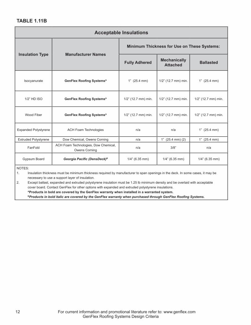
Refer to tables 1.11A & 1.11B on the following pages.C. Substrate Preparation
1. In a reroofing application, the building owner or owner’s representative is responsible for ensuring that all wet insulation and/or wet substrate has been removed and replaced. The best diagnostic technique to determine this is to take a series of roof core cuts and analyze them for moisture content and degradation. Two other techniques are currently available and make this determination by indirect means: nuclear moisture detection and infrared thermography. These techniques provide measurements of factors that can be associated with the presence of moisture.
2. A positive slope is recommended to provide adequate drainage. The National Roofing Contractors Association Manual recommends that there should be no ponding water on the roofing system forty-eight (48) hours after it has stopped raining. Positive drainage is a design feature and should be addressed in the planning stage of the project. Under no circumstances is GenFlex Roofing Systems responsible for ponding water as GenFlex is not party to the structural design of the building.
3. Any existing sprayed-in-place urethane foam roofs must be removed down to the structural deck prior to the installation of a GenFlex roofing system.
4. Unless directed otherwise by the GenFlex Technical Department, existing single-ply roof systems must either be removed or cut into 10’ x 10’ (3.0 m x 3.0 m) sections of membrane and separated from the new GenFlex roof system by an approved rigid insulation board. This helps protect the new roof from the effects associated with contracting or shrinking membrane of an aged roof assembly. In either case, all flashing must be removed to the substrate, and all penetrations re-flashed according to current GenFlex specifications and details.

For current information and promotional literature refer to: www.genflex.com 11GenFlex Roofing Systems Design Criteria
TABLE 1.11A
SUBSTRATE TYPES
Immediate Substrate Type Conditions for Use as a Roof System Substrate
Plywood, OSB or Wood Plank Decks
GenFlex roof systems may be installed directly over plywood or OSB, provided the substrate is free of contamination, sharp edges, and protrusions. Wood plank decks require an approved minimum thickness insulation board. The bondable substrate, whether plywood or minimum thickness insulation, must have any voids greater than 1/4” (6.35 mm) between panels filled with a suitable material to provide a smooth, bondable surface. Where plywood is used as a direct substrate, the plywood should be attached to the structural support with screw-type fasteners, instead of nailing, to prevent damage caused by fastener back-out as the structure moves due to expansion / contraction and settling. Damage caused by building movement is excluded from warranty coverage. Pullout tests are required on OSB decks when attachment of insulation and/or membrane is achieved with mechanical securement.
Steel Deck (22 Gauge (0.76 mm) min.)
An approved minimum thickness insulation board must be used. Insulation shall be mechanically fastened with appropriate fasteners and plates. Contact GenFlex for alternative methods to attach insulation to metal decks.
Structural Concrete or Concrete Plank
An approved minimum thickness insulation board is required. Insulation can be mechanically fastened with appropriate fasteners and plates or fastened using alternative methods of insulation securement. GenFlex insulation adhesive is approved for securement when system specifications call for attachment, provided the deck has not been altered by coatings, sealants, or curing accelerants. Asphalt attachment is accepted in some cases for insulation securement but is not covered by the GenFlex warranty.
Lightweight Concrete,Cementitious Wood Fiber or Gypsum
Lightweight concrete, cementitious wood fiber, and gypsum decks must be overlaid with a minimum thickness layer of approved insulation secured directly into the lightweight deck, provided acceptable pullout values are achieved with a GenFast GypTec fastener and insulation plate. Alternative methods of insulation securement include securing the insulation through the lightweight concrete directly to the structural deck or installing a mechanically attached base sheet and mopping-in the insulation. Insulation may also be attached to cementitious wood fiber decks with GenFlex insulation adhesive.
Existing Gravel Surface BUR and Coal Tar Pitch
All loose gravel must be removed or leveled to ensure a relatively flat substrate. An approved minimum thickness insulation board is required and must comply with system requirements for the roof assembly being installed.
Smooth Surface BUR or APP/SBS Modified Bitumen Roof System
For all systems, the existing smooth surface BUR or modified bitumen must be overlaid with a minimum thickness of approved insulation acceptable for use with the system being installed and secured in accordance with the GenFlex published fastening requirements for any given insulation type.
As an exception, a separator sheet or Fleece Backed TPO System may be installed instead of a minimum thickness approved insulation board. Please consult the GenFlex Technical Department regarding suitability of using a separator sheet or Fleece Backed membrane instead of insulation.
Existing Single-Ply Membrane Roofs – All Types
In reroof situations that involve leaving the existing single-ply membrane in place, the existing membrane must be cut into 10’ x 10’ (3.0 m x 3.0 m) pieces and overlaid with an acceptable rigid insulation board to isolate the new GenFlex single-ply roof system from the original roof membrane. The rigid board type and mechanical securement of the insulation must comply with the securement requirements of the new roof system being installed.
For current information and promotional literature refer to: www.genflex.com12GenFlex Roofing Systems Design Criteria
TABLE 1.11B
Acceptable Insulations
Insulation Type Manufacturer Names
Minimum Thickness for Use on These Systems:
Fully Adhered Mechanically Attached Ballasted
Isocyanurate GenFlex Roofing SystemsA 1” (25.4 mm) 1/2” (12.7 mm) min. 1” (25.4 mm)
1/2” HD ISO GenFlex Roofing SystemsA 1/2” (12.7 mm) min. 1/2” (12.7 mm) min. 1/2” (12.7 mm) min.
Wood Fiber GenFlex Roofing SystemsA 1/2” (12.7 mm) min. 1/2” (12.7 mm) min. 1/2” (12.7 mm) min.
Expanded Polystyrene ACH Foam Technologies n/a n/a 1” (25.4 mm)
Extruded Polystyrene Dow Chemical, Owens Corning n/a 1” (25.4 mm) (2) 1” (25.4 mm)
FanFoldACH Foam Technologies, Dow Chemical,
Owens Corningn/a 3/8” n/a
Gypsum Board Georgia Pacific (DensDeck)B 1/4” (6.35 mm) 1/4” (6.35 mm) 1/4” (6.35 mm)
NOTES:1. Insulation thickness must be minimum thickness required by manufacturer to span openings in the deck. In some cases, it may be necessary to use a support layer of insulation.2. Except ballast, expanded and extruded polystyrene insulation must be 1.25 lb minimum density and be overlaid with acceptable cover board. Contact GenFlex for other options with expanded and extruded polystyrene insulations. A Products in bold are covered by the GenFlex warranty when installed in a warranted system. BProducts in bold italic are covered by the GenFlex warranty when purchased through GenFlex Roofing Systems.

For current information and promotional literature refer to: www.genflex.com 13GenFlex Roofing Systems Design Criteria
1.12 ACCEPTABLE FASTENERS & PLATESA. Roofing fasteners are used for two purposes in the installation of a roof system: insulation securement
and membrane securement. When the fastener is being utilized for membrane securement, only GenFlex fasteners and plates are acceptable for use in the assembly. On full system warranted projects and projects requiring warranty coverage of 15 years or more, only GenFlex fasteners are acceptable for use in the roof assembly. See the following Fastener Application Guide.
B. Minimum fastener penetration requirements into the roof deck are shown on the product data sheet for each fastener type. However, typical fastener penetration requirements are as follows: 1. Steel, wood plank, plywood, OSB, and concrete decks require 1” (25.4 mm) minimum fastener
penetration.2. Gypsum and cementitious wood fiber decks require 1.5” to 2” (25.4 to 38.1 mm) minimum fastener
penetration as determined by pullout tests.3. For deck types other than those listed above, please contact the GenFlex Technical Department.
TABLE 1.12A
GenFlex Fastener Application Guide
GenFlex Fastener Type
Approved Accessories
Insulation Attachment
Membrane Attachment Deck Types
GenFast #12 Fastener 1 Yes No Steel, Wood
GenFast #14 Fastener 1,4,5,6 Yes Yes Steel, Wood
GenFast #15 (WH) Fastener 1,5,7 Yes Yes Steel, Wood, Concrete
GenFast #16 MAX Fastener 7,10 No Yes Steel
GenFast #12 Preassembled Fastener & Plate N/A Yes No Steel, Wood
GenFast #15 Preassembled Fastener & Plate N/A Yes Yes Steel, Wood, Concrete
GenFast CD-10 Concrete Fastener 1,4,5,6 Yes Yes Concrete
GenFast Lite-Deck Fastener 2,8 Yes Yes Gypsum, Cementitious Wood Fiber
GenFast Purlin Fastener 5,6 No Yes Steel Purlins
GenFast GypTec Fastener 3,9 Yes Yes Gypsum, Cementitious Wood Fiber
Insulation Plate Options: 1) GenFast Insulation Plate 2) GenFast Lite-Deck Plate 3) GenFast GypTec Insulation Plate
Membrane Securement Options: 4) GenFast 2” Seam Plate 5) GenFast (WH) 2 3/8” Seam Plate 6) GenFast Bar Anchor 7) GenFast Polymer Batten Strip 8) GenFast Lite-Deck Bar 9) GenFast GypTec Seam Plate 10) GenFast 3” MAX Seam Plate
This is only a partial representation of GenFlex Roofing Systems codes. Please contact the GenFlex Technical Department if you have any code related questions regarding assemblies not referenced.
NOTE: GenFlex fasteners are required on all full system warranties. 1. GenFlex fasteners are corrosion resistant coated and comply with Factory Mutual Standard 4470. 2. Insulation fasteners shall be suitable for the insulation used. 3. All screw type fasteners shall be a minimum #14 shank diameter for membrane securement. 4. No hex head fasteners are permitted for insulation or membrane securement in GenFlex warranted systems.
GenFlex Roofing Systems requires a pullout test to be conducted by an independent agency on the following types of decks: gypsum, cementitious wood fiber, oriented strand board, lightweight concrete, concrete plank, and any metal decks lighter than 22 gauge (0.76 mm). The results must be submitted to the GenFlex Technical Department prior to project bid. Fully adhered ap-plications on decks providing less than the required 300 lb (1 334.5 N) of pullout resistance may still qualify for warranty coverage, provided the insulation is secured in accordance with the supplemental securement table on the following page and approved by the GenFlex Technical Department.
Roof Size Pullout Test Requirements Less than 10,000 ft2 (929.0 m2) 6 10,000 ft2 - 50,000 ft2 (929.0 m2 - 4 645.2 m2) 10 50,000 ft2 - 100,000 ft2 (4 645.2 m2 - 9 290.3 m2) 20 Over 100,000 ft2 (9 290.3 m2) 1 per 5,000 ft2 (464.5 m2)
CAUTION: Use appropriate fastener for substrate.
For current information and promotional literature refer to: www.genflex.com14GenFlex Roofing Systems Design Criteria
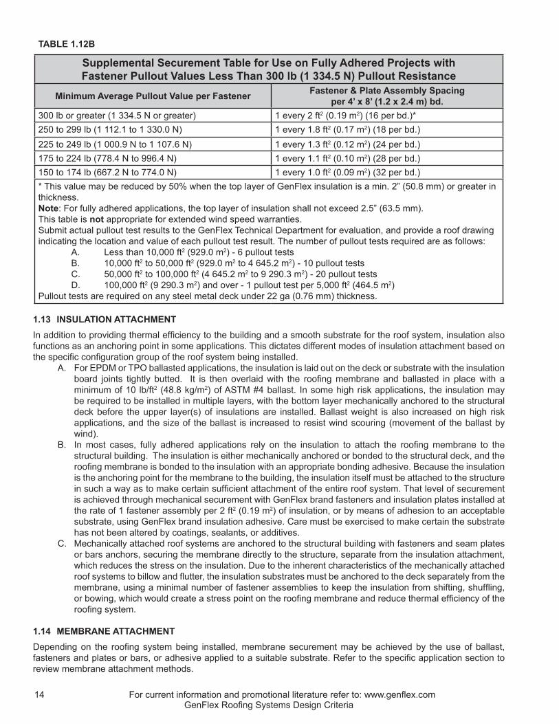
TABLE 1.12B
Supplemental Securement Table for Use on Fully Adhered Projects with Fastener Pullout Values Less Than 300 lb (1 334.5 N) Pullout Resistance
Minimum Average Pullout Value per Fastener Fastener & Plate Assembly Spacing per 4’ x 8’ (1.2 x 2.4 m) bd.
300 lb or greater (1 334.5 N or greater) 1 every 2 ft2 (0.19 m2) (16 per bd.)*250 to 299 lb (1 112.1 to 1 330.0 N) 1 every 1.8 ft2 (0.17 m2) (18 per bd.)225 to 249 lb (1 000.9 N to 1 107.6 N) 1 every 1.3 ft2 (0.12 m2) (24 per bd.)175 to 224 lb (778.4 N to 996.4 N) 1 every 1.1 ft2 (0.10 m2) (28 per bd.)150 to 174 lb (667.2 N to 774.0 N) 1 every 1.0 ft2 (0.09 m2) (32 per bd.)* This value may be reduced by 50% when the top layer of GenFlex insulation is a min. 2” (50.8 mm) or greater in thickness. Note: For fully adhered applications, the top layer of insulation shall not exceed 2.5” (63.5 mm).This table is not appropriate for extended wind speed warranties.Submit actual pullout test results to the GenFlex Technical Department for evaluation, and provide a roof drawing indicating the location and value of each pullout test result. The number of pullout tests required are as follows: A. Less than 10,000 ft2 (929.0 m2) - 6 pullout tests B. 10,000 ft2 to 50,000 ft2 (929.0 m2 to 4 645.2 m2) - 10 pullout tests C. 50,000 ft2 to 100,000 ft2 (4 645.2 m2 to 9 290.3 m2) - 20 pullout tests D. 100,000 ft2 (9 290.3 m2) and over - 1 pullout test per 5,000 ft2 (464.5 m2)Pullout tests are required on any steel metal deck under 22 ga (0.76 mm) thickness.
1.13 INSULATION ATTACHMENTIn addition to providing thermal efficiency to the building and a smooth substrate for the roof system, insulation also functions as an anchoring point in some applications. This dictates different modes of insulation attachment based on the specific configuration group of the roof system being installed.
A. For EPDM or TPO ballasted applications, the insulation is laid out on the deck or substrate with the insulation board joints tightly butted. It is then overlaid with the roofing membrane and ballasted in place with a minimum of 10 lb/ft2 (48.8 kg/m2) of ASTM #4 ballast. In some high risk applications, the insulation may be required to be installed in multiple layers, with the bottom layer mechanically anchored to the structural deck before the upper layer(s) of insulations are installed. Ballast weight is also increased on high risk applications, and the size of the ballast is increased to resist wind scouring (movement of the ballast by wind).
B. In most cases, fully adhered applications rely on the insulation to attach the roofing membrane to the structural building. The insulation is either mechanically anchored or bonded to the structural deck, and the roofing membrane is bonded to the insulation with an appropriate bonding adhesive. Because the insulation is the anchoring point for the membrane to the building, the insulation itself must be attached to the structure in such a way as to make certain sufficient attachment of the entire roof system. That level of securement is achieved through mechanical securement with GenFlex brand fasteners and insulation plates installed at the rate of 1 fastener assembly per 2 ft2 (0.19 m2) of insulation, or by means of adhesion to an acceptable substrate, using GenFlex brand insulation adhesive. Care must be exercised to make certain the substrate has not been altered by coatings, sealants, or additives.
C. Mechanically attached roof systems are anchored to the structural building with fasteners and seam plates or bars anchors, securing the membrane directly to the structure, separate from the insulation attachment, which reduces the stress on the insulation. Due to the inherent characteristics of the mechanically attached roof systems to billow and flutter, the insulation substrates must be anchored to the deck separately from the membrane, using a minimal number of fastener assemblies to keep the insulation from shifting, shuffling, or bowing, which would create a stress point on the roofing membrane and reduce thermal efficiency of the roofing system.
1.14 MEMBRANE ATTACHMENTDepending on the roofing system being installed, membrane securement may be achieved by the use of ballast, fasteners and plates or bars, or adhesive applied to a suitable substrate. Refer to the specific application section to review membrane attachment methods.

For current information and promotional literature refer to: www.genflex.com 15GenFlex Roofing Systems Design Criteria
1.15 ADDITIONAL MEMBRANE SECUREMENTRegardless of the method used to secure the field of the roofing membrane, some points on every roof require additional membrane securement. These areas include roof perimeters (parapets, transitional walls, and edges), deck angle changes in excess of 2”/12” (including drain sump areas), all curb-type roofing penetrations, pipe-type penetrations greater than 12” (304.8 mm) in diameter, both sides of expansion joints, and other areas where the membrane must be anchored to prevent movement, stress, or damage to the roofing membrane. Refer to the system details appropriate to the type of membrane being installed for securement requirements.
1.16 ROOF DRAINS & SCUPPERSA. Low slope roofs generate vast amounts of water runoff when subjected to inclement weather. Roofing drains
must be designed to handle loads that, in some cases, may completely submerge the drain assembly. It is necessary, therefore, to be certain of a sound plumbing connection as well as an adequate membrane seal to prevent backflow into the roof system. Roof drains must consist of a compression ring and matching bowl flange, include a drain basket, and be solidly connected to the building’s storm sewer plumbing. The membrane seal to the drain assembly must be made by means of a compression seal achieved by compressing GenFlex Water Stop between the membrane and the bowl flange by mechanical securement of the drain compression ring above the membrane. In cases where retrofit drains are required, the drain must meet the sealing criteria above and be mechanically sealed to the inside of the plumbing pipe. Regardless of the drain type utilized, GenFlex warranty coverage ends at the membrane-to-drain bowl seal.
B. Scuppers are typically vertically mounted flumes for water discharge. The flume is normally constructed of a suitable metal in a configuration meeting the drainage requirements of the building and is typically mounted in conjunction with a downspout conductor head to prevent exterior wall saturation due to drainage. The actual fabrication of the scupper assembly (flume and mated flange) should be constructed according to criteria detailed in the Sheet Metal and Air Conditioning Contractors National Association (SMACNA) Manual. The SMACNA Manual fully explains the points to be considered when determining the appropriate size of scuppers. GenFlex requirements regarding scuppers are as follows: for EPDM systems, the scupper assembly must be fabricated from a minimum of 24 ga (0.45 mm) G-90 steel or 0.040” (1.02 mm) aluminum. All joints must be sealed according to SMACNA standards, include a continuous 3” (76.2 mm) wide interior face flange with continuous rounded corners, be of sufficient length to extend through the exterior wall by at least 1/2” (12.7 mm), and be capable of being sealed on the exterior of the building to prevent backflow into the roof system or wall cavity. In addition to the above, if a scupper is to be mounted at the deck to wall or parapet junction, a wood nailer of equal thickness to the roofing insulation must be secured to the structural deck below the scupper flange to provide a suitable mounting surface for the scupper. Refer to the scupper detail in the general details portion of this manual.
C. Roof drainage should be sufficient to remove standing water from the roof system surface within forty-eight (48) hours after inclement weather on warranted projects. Drainage must be achieved by one of the following means: 1) Internal roof drains consisting of a compression ring and matching bowl flange, protected from debris by a drain basket, and solidly connected to the building’s storm sewer plumbing; 2) External drainage via drip edge and gutter fabricated and installed to SMACNA recommendations; 3) Scuppers and conductor heads fabricated and installed to SMACNA recommendations.
D. In many cases, proper drainage requires the use of insulation crickets to remove water adequately from around penetrations and in valley areas of structurally sloped decks. Care should also be taken when installing wood nailers along roof edges that will support metal drip edges to be certain the wood nailer is flush with the top of the roofing insulation or even slightly below (within 1/8” (3.2 mm)).
1.17 EXPANSION JOINTSA. Expansion joints allow for normal building movement without jeopardizing roof system integrity. This is
accomplished by providing a point of securement and termination for the roof system on each side of a flashed opening in the building structure. Any building movement is isolated to those controlled areas, which saves the roof from having to endure the stresses related to thermal movement and settling. In the event an expansion joint is deemed appropriate, it is the responsibility of the roof designer to determine the type, location, and installation method.
B. A partial list of conditions requiring consideration in regard to whether a roof expansion joint is called for follows:1. Over any expansion joint in the structural substrate over which a roof system will be installed.2. At connection points between existing buildings and new additions.3. Any time structural elements, such as steel beams, bar joists, or decking material, change direction.

For current information and promotional literature refer to: www.genflex.com16GenFlex Roofing Systems Design Criteria
4. At connection points between dissimilar deck materials.5. Over interior partitions within a building which establish different interior climatic conditions, e.g. over
walls dividing heated and unheated spaces and partitions between cold storage and office space, etc.6. Anywhere movement between deck and parapet wall is anticipated.7. As required by the design professional based on thermal coefficients of the building materials and the
anticipated building movement related to normal expansion and contraction.
1.18 PENETRATION POCKETSPenetration pockets are used to flash irregularly shaped or densely concentrated roof penetrations and are typically fabricated of metal in a configuration allowing for placement around a fixed object. Penetration pocket fabrication techniques can be found in the SMACNA manual. GenFlex offers GenPocket E and GenPocket T, vacuum formed penetration pockets designed for use with EPDM and TPO systems, respectively. Field fabricated penetration pockets may be acceptable for use in a warranted assembly. Contact the GenFlex Technical Department for options. The goal when creating a penetration pocket is to form a pocket at least 2” (50.8 mm) deep and of sufficient size to accommodate the roof penetration and 1” (25.4 mm) on all sides of the penetration. In cases of multiple penetrations, a 1” (25.4 mm) space must be maintained between all penetrations and the walls of the penetration pocket. Once this containment area is constructed, it is to be flashed with GenFlex flashing material, with the flashing terminating inside of the pocket. Once flashed, the penetration pocket can be filled with GenFlex Pourable Sealer to a point that the pocket is full and mounded in order to shed water. The pourable sealer pocket must be fabricated with a continuous 3” (76.2 mm) wide base flange with rounded corners. Pourable sealer pockets greater than 18” (457.2 mm) wide on any side require securement to a wood nailer through the roofing membrane prior to flashing, in order to provide base flashing securement of the surrounding field membrane. Penetration pockets and pourable sealer are considered tie-ins to products by others and are an owner maintenance item outside of GenFlex warranty coverage.
1.19 ROOF CURBSRoof curbs typically serve three purposes: supporting rooftop equipment, leveling and raising the equipment to an appropriate flashing height, and providing a suitable substrate to tie-in the roof system. Curbs can be fabricated from metal, wood or, in special applications, structural plastic and fiberglass. The basic components of a roof curb are the base, which generally includes a flange to be mounted to the structural deck, a support surface to which equipment can be mounted and, in some cases, a wood nailer into which the roofing system is terminated. If circumstances prevent mounting the curb to the structural deck, the curb must be supported on a continuous wood nailer wider than the mounting flange and equal in height to the installed roof insulation. Curbs cannot be supported by roof insulation alone due to the compressible nature of insulation, unless the supported load on the curb is less than 25 lb (11.3 kg). Curb height must be minimum 8” (203.2 mm) from finished roof surface.
1.20 ROOF PENETRATIONS (NON-CURB)A roof penetration is anything that protrudes from the roof surface that must be flashed. Penetrations include plumbing vents, structural support elements, conduit, etc. In cases where the penetration is round with one end free of obstructions, the preferred method of flashing is to install a pre-molded pipe boot. When a pipe boot cannot be utilized, the penetration must be addressed with either a field wrap flashing or a penetration pocket around the protrusion.
1.21 WALLS & PARAPETSWall and parapet flashing is accomplished by securing the field membrane at the angle change of the roof and vertical substrate. A layer of field membrane is bonded to the vertical substrate, forming a counter-flashing for the base tie-in detail, which is then seamed onto the field sheet of membrane, using the appropriate GenFlex seaming method. When a coping cap is intended for use on a project, GenFlex standard details require wall or parapet flashing to extend over the top of the wall or parapet and turn down the exterior surface of the wall or parapet to a point where any installed wood nailer is covered, and any water that penetrates the metal coping drains onto the exterior weatherproof finish and not into the wall cavity.
A. In addition to using deck membrane with field-applied bonding adhesive as flashing material, TPO systems may utilize our Peel & Stick TPO products as vertical flashings with the added benefit that the requirement for intermediate securement is eliminated. (See Technical Memo dated July 2004). The Peel & Stick product is available in a variety of widths for use as wall and parapet flashing on TPO systems and offers the advantage of the capability of being positioned on the vertical substrate before the release liner is removed, thus bonding the membrane to the substrate. This advantage results in an aesthetically superior parapet flashing as compared to flashing applied with field-applied adhesives.

For current information and promotional literature refer to: www.genflex.com 17GenFlex Roofing Systems Design Criteria
B. Parapets and walls in excess of 24” (609.6 mm) in height for TPO (See note “A” above), and 48” (1.2 m) in height for EPDM, require intermediate securement. Refer to the appropriate detail for intermediate membrane securement requirements.
C. Parapets and walls in excess of 48” (1.2 m) in height assembled with other than structural substrate material will require vertically mounted (secured to the studs) intermediate membrane securement. Structural material is defined as plywood, concrete, masonry, steel, etc. Spacing of the vertical intermediate securement will be maximum 48” (1.2 m) o.c.
1.22 TIE-INS TO DISSIMILAR MATERIALS, OTHER ROOF SYSTEMS, ETC.Some roof applications require tie-in to dissimilar materials, such as roof systems by others, irregularly shaped penetrations, multiple penetrations installed too closely to be addressed separately, and terminations into foreign substrates, e.g. concrete or masonry walls and metalwork by others, etc. A successful tie-in will separate and isolate the dissimilar materials and provide a watertight seal. Tie-ins can be accomplished with specialized details and, in cases of irregularly shaped penetrations or penetrations mounted too closely to be addressed separately, by using a suitable, flashed containment detail and pourable sealer. Refer to the tie-in details for the type of membrane being installed. For applications not covered in our standard details, contact the GenFlex Technical Department. Tie-ins to other roofing systems or dissimilar materials are not covered by the GenFlex Roofing Systems Warranty.
1.23 FLASHINGSA. Minimum vertical height for field-applied membrane flashings (cured and uncured) is 8” (203.2 mm) above
the finished roof surface. Care must be taken not to cover any weep holes or through wall flashings. B. Besides masonry substrates (concrete, brick or block), wood sheathing, and moisture resistant exterior
grade gypsum board may also be used for parapet wall sheathing. If the substrate is to be gypsum, the gypsum sheathing must be fiberglass reinforced exterior grade board and be recommended for use as a sub-roof sheathing material by the board manufacturer. 1. When gypsum is used as a vertical flashing substrate, the bottom 12” (304.8 mm) of parapet or wall
must be sheathed with 5/8” (15.9 mm) exterior grade plywood secured to the metal studs in an industry accepted manner in order to provide a substrate suitable for base flashing securement. This option is only applicable when the finished flashing height is intended to be terminated with a coping cap or gravel stop detail because wood and gypsum are not suitable compression termination substrate materials.
2. When the option above cannot be used with a gypsum sheathed wall or parapet, the base flashing securement must be moved to the deck surface and be accomplished with an approved GenFlex horizontal base flashing securement detail secured per the specifications of the system being installed. The appropriate fasteners shall not exceed 6” (152.4 mm) in length. If the insulation thickness prevents fasteners 6” (152.4 mm) or shorter from achieving proper penetration appropriate for the deck type, wood nailers will be required to be installed and anchored to the deck to build up a securement point at a height suitable for a 6” (152.4 mm) long fastener or shorter to perform as intended. When nailers are required in this configuration, install insulation tightly to the nailer, with no gaps greater than 1/4” (6.4 mm) wide, and stagger insulation joints as much as possible to preserve thermal efficiency.
3. Parapets and walls sheathed with gypsum exceeding the flashing heights defined in item D below require special attention in regard to intermediate membrane attachment. Refer to the appropriate detail in the details sections of this manual.
C. Parapet and wall surfaces too rough or uneven to provide a suitable bonding surface for the membrane flashing (or constructed of an incompatible material) may be sheathed or overlaid with mechanically anchored 5/8” (15.9 mm) thick exterior grade plywood and flashed in accordance with GenFlex specification. If sheathing is used, a clean area of substrate must be available above the sheathing for the membrane termination, unless the wall or parapet is intended to be capped with coping. In this case, the membrane will need to extend up and over the parapet top.
D. Parapets and transitional walls exceeding height limits set for each specific type of roofing membrane require intermediate securement. The height limits for each type of membrane are as follows:1. EPDM - 4’ (1.2 m)2. TPO - Standard - 2’ (609.6 mm)3. Peel & Stick TPO - not applicable
a. For structural substrates, such as plywood, masonry, or concrete, securement may be achieved with use of an anchor bar secured at 12” (304.8 mm) o.c. with a GenFlex fastener of appropriate type and length for the vertical substrate, through the flashing material and counter-flashed with a

For current information and promotional literature refer to: www.genflex.com18GenFlex Roofing Systems Design Criteria
subsequent membrane panel. It may also be achieved by securing a GenFast Bar Anchor through a continuous membrane sheet to the vertical substrate at 12” (304.8 mm) o.c. with a GenFlex fastener of appropriate type and length and then stripping in the bar anchor with a properly applied batten style cover of a system appropriate material. Refer to the appropriate details in the detail section of this manual.
b. For substrates other than structural, the intermediate membrane securement will need to be mounted vertically and secured through the substrate to the structural members (metal or wood studs). Refer to the appropriate details in the detail section of this manual.
E. Whenever a surface-mounted termination is specified for a masonry or concrete substrate, it is important to remember that any surface-mounted termination is only as effective as the waterproofing material on the substrate above it, or the effectiveness of any through wall flashing and weep hole system. If the vertical substrate above a surface-mounted termination cannot be made waterproof, it may be necessary to flash the entire wall and install a coping cap or similar termination. Do not under any circumstance encapsulate weep systems within a flashed wall. Weep systems address moisture originating from the exterior exposed surface of the exposed wall or parapet and would convey water into the finished roof system.
1.24 METALWORK
A. Metalwork is not waterproofing. The installed membrane and roofing system must be made watertight before metal application.
B. No roof system is complete until all the edges are terminated in such a way as to prevent water infiltration into the roofed structure. This typically involves the use of manufactured or shop fabricated metal detailing, such as coping caps, gravel stops, roof edging, flashing and counter-flashing components. All metalwork should be fabricated and installed according to SMACNA and National Roofing Contractors Association (NRCA) guidelines. Unless specifically agreed to in writing by the GenFlex Technical Department prior to installation, metalwork manufactured by others is not included in the GenFlex warranty coverage.
C. The designer and roofing contractor should be aware that many municipalities and states are beginning to enforce metal codes that, until recently, were merely used as guidelines. These metal codes relate to minimum standards on material, fabrication, and testing of roof related metalwork. It is the contractor’s responsibility to review and know the building codes relating to their roofing projects in order to avoid costly remedial work to bring a project into compliance.
D. If the metalwork on a project is specified by the designer to be included in a full system warranty, use GenFlex brand edge metal and coping products. Contact your Territory Sales Manager or Sales Representative for information.
E. If a metal flashing product by others is submitted via a deviation request for inclusion in the warranty coverage, the following are minimum requirements for consideration: 1. The metalwork must be shop or factory formed or extruded.2. The metalwork must be configured and installed in accordance with SMACNA guidelines and NRCA
installation instructions.3. Minimum requirements regarding metalwork material are, 24 ga (0.61 mm) G-90 Kynar pre-finished
steel or 0.040” (1.02 mm) aluminum (mill finished, pre-finished or anodized). 4. A deviation request for inclusion of metalwork in warranty coverage must accompany the Pre-Job
Survey form submitted by the installing contractor.5. The deviation request must include shop drawings of the metalwork to be included and a roof plan
showing the installed location and linear dimension for each profile. 6. Should the deviation request be granted, the installing contractor will be responsible to GenFlex
Roofing Systems for a period of two-years from the date of GenFlex inspection and acceptance under their installers agreement.
F. Metalwork installation, regardless of material source, must be according to the metalwork manufacturer’s instructions available from the manufacturer or supplier. 1. Metalwork formed by roofing contractors must be fabricated and installed in accordance with
SMACNA and NRCA recommendations. All flange-mounted metalwork must be flashed according to the appropriate GenFlex material type’s standard details. Metalwork formed by contractors is not eligible for warranty coverage unless the conditions listed under item “D” above are met, and GenFlex accepts the metalwork for warranty coverage in writing.
2. Metalwork by roofing contractors must have metal joints stripped-in to the uppermost edge of the metal dam on the roof side.

For current information and promotional literature refer to: www.genflex.com 19GenFlex Roofing Systems Design Criteria
3. EPDM and TPO projects with cover tape flange strip-in of metalwork with a gravel dam (or a formed configuration that is capable of holding water on the edge of the installed cover tape) must have edge caulk applied on both sides of the cover tape.
G. The approval of metalwork for inclusion in warranty coverage is conditional upon acceptance by GenFlex Roofing Systems, and, if approved, is subject to the “terms, conditions and limitations” of the requested warranty. Under no circumstance will any warranty coverage for metalwork exceed the wind speed limitation of the warranty issued for the roof system. Aesthetic appearance is expressly excluded from warranty coverage.
H. Metalwork by others is not permitted on projects requiring full system warranties and wind speed coverage equal to, or greater than, 90 mph (144.8 km/h).
1.25 WALKWAYS Walkways are required at all access points to the roof system. Walkways are recommended anywhere routine (once a month or more) traffic on the membrane surface is anticipated. Walkway pads are used to protect the weatherproofing membrane from excessive wear and tear. Traffic-related roof damage is not covered by the GenFlex warranty. In areas of extreme traffic, contact GenFlex for options to enhance the roof system in order to prevent or mitigate traffic-related insulation damage. Walkway maintenance is the responsibility of the property owner because walkway pads are not part of the waterproofing assembly.Should access to the weatherproofing membrane be required in order to perform warranty service to the roof system, only GenFlex brand walkway pads will be moved and replaced as necessary to perform service at GenFlex’s expense. Pavers, walkway systems, patio surface components and other products neither manufactured nor supplied by GenFlex Roofing Systems that impede roof system service must be removed and replaced at the building owner’s expense. Should the obstacle removal and replacement be performed by the GenFlex Licensed Contractor servicing the leak call under building owner authorization and/or purchase order, GenFlex assumes no responsibility or liability for the performance of the contractor in performing that service.
1.26 FINISHED ROOF PROTECTIONWhen it becomes necessary for other trades to work over a completed area of new roof, the roofing membrane and flashing must be protected from physical damage. Proper and adequate protection includes installing a slip-sheet in the work area overlaid with plywood or OSB in order to dissipate the effects of traffic on the finished roof surface and to prevent impact damage to the system caused by dropped tools and/or equipment. If damage does occur to the roof system, it must be repaired immediately in order to preserve the integrity of the roof system. If the membrane is damaged in more than 6 locations within a 100 ft2 (9.3 m2) area, apply an area overlay of matching membrane extending 6” (152.40 mm) beyond the border of the damaged areas, and seam into place in accordance with GenFlex seaming specifications. For fully adhered and mechanically attached applications, the membrane must be fully bonded to the existing underlying membrane with an appropriate adhesive. Contact the GenFlex Technical Department with any questions on how to address comprehensive damage.
1.27 OWNER ROOF MAINTENANCE & CLEANING Maintenance
A. A new roof system is a major investment for any building owner. To ensure roof system performance and prolong the service life of the roofing assembly, it is important to control access to the finished roof system (written access log) and to perform routine roof inspections and maintenance. Roof inspections should take place twice a year (in the spring and fall) and after any severe climatic event (high winds, tornado, hail storm, etc.). Regular maintenance items include the following: 1. Clearing roof drains, scuppers, gutters and downspouts of debris to facilitate adequate drainage.2. Identifying any loose or damaged metalwork by others. Most wind-related roof damage initiates at the roof
edge and is related to metalwork becoming loose or dislodged.3. Inspecting for physical damage to the roofing membrane, especially in any areas surrounding rooftop
equipment or points of access.4. Inspecting for curb-mounted equipment issues (HVAC unit door open, clogged condensation lines that
may present as a roof leak, etc.).5. Inspecting the overall condition of the roof system, looking for signs of wind damage, which may appear
as loose flashing on a wall, displaced roof ballast, displaced rooftop equipment, or debris on the roof system.
B. All counter-flashing, metalwork, equipment curb and supports, pitch pockets, caulking, grease guards, traps, secondary sheets, walkway pads, and any other rooftop accessories functioning in conjunction with the
For current information and promotional literature refer to: www.genflex.com20GenFlex Roofing Systems Design Criteria
membrane roofing system are to be properly maintained at all times. If a secondary (sacrificial) sheet is used to protect an area around a stack or vent, it should be inspected and replaced if deterioration occurs. Walkway pads are to be maintained by the building owner and are not covered by the GenFlex warranty.
C. Ponded water (defined as standing water on the roof for more than forty-eight (48) hours after inclement weather has stopped) must not be allowed on EPDM roofs. Roofs must have sufficient slope to drain properly, and all drain areas must remain clean in order to function properly. Remove all debris from the roof, since debris on the roof surface may be swept into drains by rain water.
D. Materials and equipment should not be stored on the roof. Remove broken bottles, metal, etc., and immediately report any damage or vandalism to GenFlex Roofing Systems. Contact GenFlex Roofing Systems in writing for approval if additional equipment is to be installed on or through the roof system; e.g. HVAC units, antennas, camera mounts, etc.
E. Regular cleaning must be done in areas where potentially harmful contaminants, such as oil, grease, freon, acids, or solvents, may accumulate. Periodic cleaning of white or colored roof membranes may be necessary to maintain the membrane’s reflective properties and aesthetic appearance. Contact the GenFlex Roofing Systems Technical Department for any additional preventative maintenance information. Note: Roof damage related to chemical exposure and surface contamination is excluded from GenFlex warranty coverage.
F. If there will be foot traffic on the finished roof surface for any reason, walkway pads are recommended. In cases of extreme traffic, or if you anticipate the movement of wheeled loads across the roof surface, contact the GenFlex Roofing Systems Technical Department to discuss options to enhance the roof system in the traffic areas before damage occurs. Note: Roof damage related to rooftop traffic is excluded from GenFlex warranty coverage.
G. Many GenFlex contractors offer maintenance programs on the roofs they install. Roof Membrane Cleaning
H. All exposed low slope roofing membranes get dirty over the life of the roof system from airborne pollutants and dirt. The accumulation of dirt on a dark colored roof surface is less noticeable than on a light colored or white membrane. The amount and type of accumulation is related to the location of the installed roof system. Each type of “dirt” requires a slightly different approach and level of effort to remove from a roof surface.
I. There are two possible issues when a light colored roof system becomes dirty: 1. Aesthetics: If the roof surface is visible from the road or adjacent buildings, it may be preferential to
maintain a decorative appearance versus utilitarian. 2. Energy Efficiency: With current design initiatives, more and more designers are looking toward
environmentally friendly roof designs to reduce energy costs, save natural resources, and reduce the effects that commercial roofs have on the natural weather patterns (heat island).
J. Low slope roofing membrane manufacturers, GenFlex Roofing Systems included, exclude aesthetics from warranty coverage as an uncontrollable variable.
K. Should the building owner wish to clean his roof to restore the reflectivity or aesthetic appearance of the membrane, an equipment list and directions for cleaning a GenFlex warranted roof system are below. It is the owner’s responsibility to become familiar with, and abide by, local and regional codes and laws regarding acceptable cleaning soaps and proper disposal of cleaning water.
L. Required equipment: soft bristle brooms, mops, squeegees. 1. Broom clean the roof surface. This will remove loose dirt and debris that might clog the drains or abrade
the membrane surface during washing.2. Wet the roof surface and allow to “soak” for five (5) minutes to soften any dried dirt.3. Loosen the dirt from the membrane surface by sweeping the wet surface with a soft bristle broom.4. Rinse the area of membrane being worked on to assess the effectiveness of cleaning with water alone. 5. If there is still dirt on the membrane, wet the roof surface, and allow to soak for five minutes.6. While soaking, apply a sprinkling of Spic and Span® or Tri-Sodium Phosphate (available at most paint
stores) to the wetted membrane. 7. Rescrub the membrane with the soft bristle broom.8. Rinse with clean water before the soap residue dries on the roofing membrane.9. The above steps will remove most forms of dirt. If one washing does not remove the dirt, you may need
to repeat steps 1-8.Cautions and warnings: Damage to the roof during washing operations is not covered under the GenFlex warranty. If damage occurs during washing, it is the responsibility of the owner to repair. Do NOT abrade the surface of the roof membrane. Seams are typically laid shingle fashion towards the roof drain or gutter. Do not agitate, power wash, or scrub against the seam. Go over the top of the seam or parallel to it.

For current information and promotional literature refer to: www.genflex.com 21GenFlex Roofing Systems Design Criteria
M. A commercial roof system is a major investment for a property owner. It is important to protect the roof system from accidental damage during cleaning. Before hiring the project out to a local GenFlex contractor, there are a few things to consider. 1. Building owner assumes all risk for damage to the roofing membrane during the cleaning process. Use
extreme caution in performing the work yourself or hiring a contractor for the job.2. The GenFlex Technical Department is available for assistance in writing the scope of work. 3. Many GenFlex installers also offer roof cleaning services.4. Perform a full visual inspection of the roof system before and after cleaning the roofing membrane to
identify any preexisting roof damage and to verify the effectiveness of the cleaning process. It may prove beneficial to take photographs of the roof system before cleaning begins.
5. Do not use, or allow anyone else to use, a floor scrubber on the membrane.6. Pressure washing equipment can severely damage roofing membrane if not used by a professional
with membrane roof cleaning experience. If a pressure washer is used in cleaning the roof membrane, please keep the following items in mind: a. Do not use any pressure washer tip less than a 30° arc. Tips with a concentration angle smaller than
30° will damage the roofing membrane.b. Do not use a rotating tip apparatus.c. Maintain a minimum of 24” (609.6 mm) between the pressure washer nozzle tip and the roofing
membrane.d. Do not use a pressure washer rated higher than 2500 psi (17.2 MPa).
7. Always get a current certificate of liability insurance from the contractor performing the work, with your company listed as an additional insured party.
8. If you suspect the warranted roof system may have been damaged during the cleaning process, contact the GenFlex Technical Department immediately.
PART 2 – PRODUCTS
2.01 GENERAL A. The components of the GenFlex roof system are to be products of GenFlex Roofing Systems or approved
by GenFlex Roofing Systems as compatible and acceptable. Unless specifically included in the warranty coverage by GenFlex Roofing Systems, products by others are excluded from coverage.
2.02 MEMBRANE A. GenFlex standard and fabric reinforced EPDM and thermoplastic membranes are available in a variety
of membrane thickness and sheet width combinations that are illustrated in the table below. Not all sheet lengths shown are stock items. Consult your GenFlex Customer Service Representative regarding lead time for nonstock sheet length / width combinations.
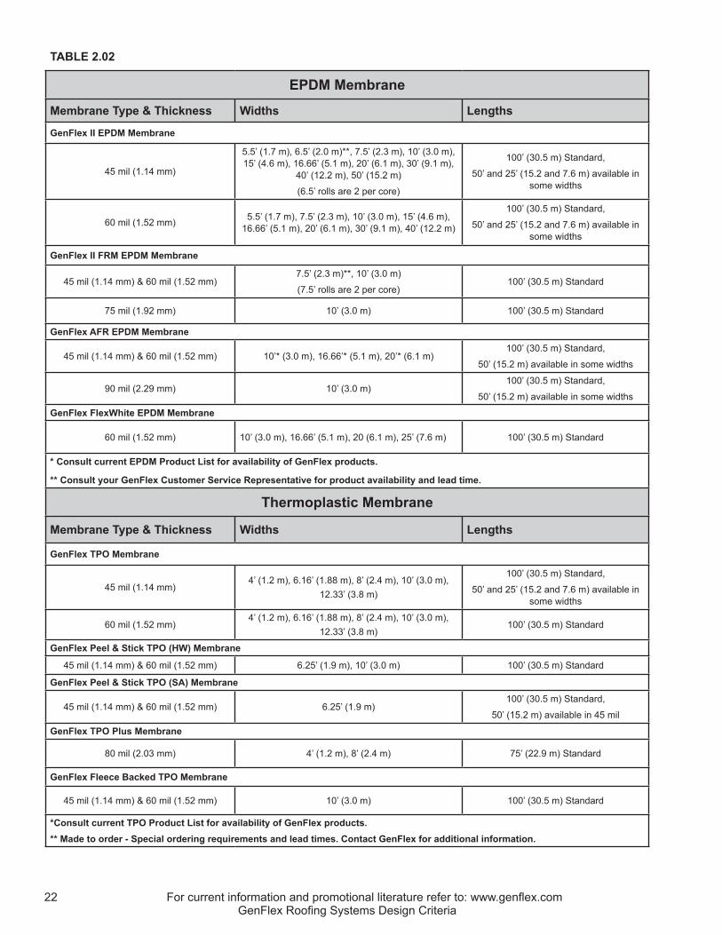
For current information and promotional literature refer to: www.genflex.com22GenFlex Roofing Systems Design Criteria
TABLE 2.02
EPDM Membrane
Membrane Type & Thickness Widths Lengths
GenFlex II EPDM Membrane
45 mil (1.14 mm)
5.5’ (1.7 m), 6.5’ (2.0 m)**, 7.5’ (2.3 m), 10’ (3.0 m), 15’ (4.6 m), 16.66’ (5.1 m), 20’ (6.1 m), 30’ (9.1 m),
40’ (12.2 m), 50’ (15.2 m)
(6.5’ rolls are 2 per core)
100’ (30.5 m) Standard,
50’ and 25’ (15.2 and 7.6 m) available in some widths
60 mil (1.52 mm) 5.5’ (1.7 m), 7.5’ (2.3 m), 10’ (3.0 m), 15’ (4.6 m), 16.66’ (5.1 m), 20’ (6.1 m), 30’ (9.1 m), 40’ (12.2 m)
100’ (30.5 m) Standard,
50’ and 25’ (15.2 and 7.6 m) available in some widths
GenFlex II FRM EPDM Membrane
45 mil (1.14 mm) & 60 mil (1.52 mm) 7.5’ (2.3 m)**, 10’ (3.0 m)
(7.5’ rolls are 2 per core)100’ (30.5 m) Standard
75 mil (1.92 mm) 10’ (3.0 m) 100’ (30.5 m) Standard
GenFlex AFR EPDM Membrane
45 mil (1.14 mm) & 60 mil (1.52 mm) 10’* (3.0 m), 16.66’* (5.1 m), 20’* (6.1 m)100’ (30.5 m) Standard,
50’ (15.2 m) available in some widths
90 mil (2.29 mm) 10’ (3.0 m)100’ (30.5 m) Standard,
50’ (15.2 m) available in some widths
GenFlex FlexWhite EPDM Membrane
60 mil (1.52 mm) 10’ (3.0 m), 16.66’ (5.1 m), 20 (6.1 m), 25’ (7.6 m) 100’ (30.5 m) Standard
* Consult current EPDM Product List for availability of GenFlex products.
** Consult your GenFlex Customer Service Representative for product availability and lead time.
Thermoplastic Membrane
Membrane Type & Thickness Widths Lengths
GenFlex TPO Membrane
45 mil (1.14 mm)4’ (1.2 m), 6.16’ (1.88 m), 8’ (2.4 m), 10’ (3.0 m),
12.33’ (3.8 m)
100’ (30.5 m) Standard,
50’ and 25’ (15.2 and 7.6 m) available in some widths
60 mil (1.52 mm)4’ (1.2 m), 6.16’ (1.88 m), 8’ (2.4 m), 10’ (3.0 m),
12.33’ (3.8 m)100’ (30.5 m) Standard
GenFlex Peel & Stick TPO (HW) Membrane
45 mil (1.14 mm) & 60 mil (1.52 mm) 6.25’ (1.9 m), 10’ (3.0 m) 100’ (30.5 m) Standard
GenFlex Peel & Stick TPO (SA) Membrane
45 mil (1.14 mm) & 60 mil (1.52 mm) 6.25’ (1.9 m)100’ (30.5 m) Standard,
50’ (15.2 m) available in 45 mil
GenFlex TPO Plus Membrane
80 mil (2.03 mm) 4’ (1.2 m), 8’ (2.4 m) 75’ (22.9 m) Standard
GenFlex Fleece Backed TPO Membrane
45 mil (1.14 mm) & 60 mil (1.52 mm) 10’ (3.0 m) 100’ (30.5 m) Standard
*Consult current TPO Product List for availability of GenFlex products.** Made to order - Special ordering requirements and lead times. Contact GenFlex for additional information.

For current information and promotional literature refer to: www.genflex.com 23GenFlex Roofing Systems Design Criteria
2.03 RELATED MATERIALS The following list contains the names of other GenFlex products and accessories that may be required in order to complete the roofing system. With the exception of walkway pads, which are considered maintenance items, GenFlex manufactured or supplied material is covered in the limited warranty, provided a warranty is purchased for the project. NOTE: Prolonged exposure of adhesives and sealants to temperatures greater than 80 °F (27 °C) will reduce their shelf life. Shelf life is indicated on the product label or in the product information data for the particular product item, which can be found at www.genflex.com.
EPDM Product DescriptionsA. EPDM Flashing 6”, 9”, 12”, 18”, or 24” wide x 100’ per roll (152.4 mm, 228.6 mm, 304.8 mm, 457.2 mm, or 609.6 mm x 30.5 m)B. EPDM Seam Tape 3” x 50’ or 100’ (76.2 mm x 15.2 m or 30.5 m) or 7” x 100’ (177.8 mm x 30.5 m) per rollC. EPDM Cover Tape 6” x 25’ or 100’ (152.4 mm x 7.6 m or 30.5 m) or 12” x 100’ (304.8 mm x 30.5 m) per rollD. Peel & Stick EPDM Flashing 7” x 100’ (177.8 mm x 30.5 m) or 9” x 25’ or 50’ (228.6 mm x 7.6 m or 15.2 m) per rollE. Peel & Stick EPDM RPS 6” x 100’ per roll (152.4 mm x 30.5 m)F. EPDM Pipe Boot 1” to 6” (25.4 to 152.4 mm) / 10 per ctnG. GenPocket E 6.7” (170.2 mm) diameter / 6 per ctnH. Peel & Stick EPDM Pipe Boot 1” to 6” (25.4 to 152.4 mm) / 10 per ctnI. Peel & Stick EPDM Corner 9” (228.6 mm) diameter / 20 per ctnJ. Peel & Stick EPDM T-Joint Cover 8” x 10” (203.2 x 254.0 mm) / 25 per boxK. Flexguard Peel & Stick Walkway Pad 30” x 30” x 5/16” (762.0 x 762.0 x 7.9 mm) / 50 per palletL. GenPrime 275 to 450 lf/gal (22.1 to 36.2 m/L) for 3” (76.2 mm) seam tape or 180 to 225 lf/gal (14.5 to 18.1 m/L) for 6”(152.4 mm) seam tape or 300 to 375 lf/gal (24.2 to 30.2 m/L) for 6” (152.4 mm) cover tape) (Adjust accordingly for other products.)M. GenPrime LVOC 150 to 225 ft2/gal (3.7 to 5.5 m2/L) for one-sided applicationN. EPDM Bonding Adhesive 45 to 60 ft2/gal (1.1 to 1.5 m2/L) of finished surfaceO. EPDM Bonding Adhesive LVOC 45 to 60 ft2/gal (1.1 to 1.5 m2/L) of finished surfaceP. Scrub Pad & Handle 3” x 5” (76.2 x 127.0 mm) / 30 pads & 4 handles per ctn Q. EPDM Edge Caulk LVOC 15 lf to 20 lf (4.6 to 6.1 m) per tube / 12 tubes per ctnR. Ace Coating 100 ft2/gal (2.5 m2/L) / 5 gallon (18.9 L) pail
FLEXWHITE EPDM A. FlexWhite Peel & Stick Flashing 12” x 25’ (304.8 mm x 7.6 m) / 1 roll per ctnB. FlexWhite Peel & Stick Pipe Boot 1” to 100’ (25.4 mm x 30.5 m) / 10 per ctnC. FlexWhite Peel & Stick Cover Tape 6” x 100’ (152.4 mm x 30.5 m) / 2 rolls per ctnD. FlexWhite Peel & Stick Flashing 12” x 25’ (304.8 mm x 7.6 m) / 1 roll per ctnE. FlexWhite Peel & Stick T-Joint Cover 5 3/4” round / 25 per ctnF. FlexWhite Peel & Stick Corner 8 1/2”round (215.9 mm) / 20 per ctnG. FlexWhite Seam Tape 3” x 100’ 76.2 mm x 30.5 m) / 4 rolls per ctnH. FlexWhite Clear Primer 3 gal (11.4 L) pailI. FlexWhite Edge Caulk 11 fl oz (325.3 mL) / 12 per ctn
TPOA. TPO Non-Reinforced Flashing 24” x 50’ (609.6 mm x 15.2 m)B. TPO Inside/Outside Corner 1 size / 10 per ctnC. TPO Reinforced Outside Corner 12” x 12” (304.8 x 304.8 mm) / 10 per ctnD. TPO Molded Pipe Boot 1” to 6” (25.4 to 152.4 mm) / 10 per ctnE. TPO Pipe Boot - Small 1” to 3” (25.4 x 76.2 mm) / 10 per ctnF. TPO Pipe Boot - Large 3” to 6” (76.2 x 152.4 mm) / 10 per ctnG. TPO T-Joint Cover 4.5” (114.3 mm) diameter / 100 per ctnH. GenPocket T 6” (152.4 mm) diameter / 6 per ctnI. TPO Heat Weldable Walkway Pad 30” x 50’ (762.0 mm x 15.2 m) / 1 rollJ. TPO Coated Metal 4’ x 10’ (1.2 x 3.0 m) / 10 sheets per pallet

For current information and promotional literature refer to: www.genflex.com24GenFlex Roofing Systems Design Criteria
K. Peel & Stick TPO RPS 6” x 100’ (152.4 mm x 30.5 m) / 2 rolls per ctn (Reinforced Perimeter Strip) L. Peel & Stick TPO RMA 10” x 100’ (254.0 mm x 30.5 m) / 1 roll per ctn (Roof Membrane Attachment Strip) M. TPO Seam Tape 3” x 50’ (76.2 mm x 15.2 m) / 4 rolls per ctn / 3” x 100’ (76.2 mm x 30.5 m) / 1 roll per box, 6 box per ctnN. Clear Primer 3 gal (11.4 L) or 1 qt. (0.9 L) canO. Clear Primer LVOC 1 gal (3.8 L) / 4 pails per ctn or 3 gal ( 11.4 L) pailP. Substrate Primer 1 gal (3.8 L) / 4 pails per ctnQ. TPO Cover Tape 5.5” x 25’ (139.7 mm x 7.6 m) / 1 roll per box, 4 box per ctnR. Peel & Stick TPO Pipe Boot 1” to 6” (25.4 to 152.4 mm) / 8 per ctnS. Scrub Pad & Handle 3” x 5” (76.2 x 127.0 mm) / 30 pads & 4 handles per ctnT. TPO Bonding Adhesive 5 gal (18.9 L) pailU. TPO Bonding Adhesive LVOC 5 gal (18.9 L) pailV. FB Bonding Adhesive (LVOC) 5 gal (18.9 L) pail W. TPO Edge Sealant 16 fl oz (532.3 mL) / 12 bottles per ctnX. TPO Edge Caulk LVOC 11 fl oz (325.3 mL) / 12 tubes per ctn
UNIVERSAL ACCESSORIESInsulation Polyiso (flat or tapered), 1/2” HD ISO, Wood Fiber GenFast Fastener #12, #14, #15 (WH), #16 MAX, CD-10, Purlin, Lite-Deck,
GypTec / quantity per ctn variesGenFast Insulation Plate 3” Round, Lite-Deck, GypTec / quantity per ctn variesGenFast Seam Plate 2”, 2 3/8” (WH), 3” MAX, GypTec, RF, AS / quantity per ctn variesGenFast Bar Anchor 1” x 10’ (25.4 mm x 3.0 m) / 50 per tubeGenFast Polymer Batten Strip 1” x 250’ (25.4 mm x 76.2 m) GenFast Lite-Deck Bar 1” x 10’ (25.4 mm x 3.0 m) / 500’ (152.4 m) per tubeGenFast Preassembled Fastener & Plate #12, #15 / quantity per ctn variesCleaner 5 gal (18.9 L) pailsOne Step Insulation Adhesive 200 ft2 (18.6 m2) per ctn for 4” (101.6 mm) o.c. bead 300 ft2 (27.9 m2) per ctn for 6” (152.4 mm) o.c. bead 600 ft2 (55.7 m2) per ctn for 12” (304.8 mm) o.c. bead All Purpose Bonding Adhesive 45 to 60 ft2/gal (1.1 to 1.5 m2/L) of finished surfaceAll Purpose Water Based Bonding Adhesive 120 ft2/gal (2.9 m2/L) / 1, 3.5 or 5 gallon pail (3.8, 13.2 or 18.9 L) Pourable Sealer (A & B) 1 ft2/gal at 2” thick (0.02 m2/L at 50.8 mm thick)Water Stop 15 lf (4.6 m) per tube / 12 tubes per ctnTermination Caulk 24 lf (7.3 m) per tube / 12 tubes per ctnGenFast Termination Bar 1.25” x 10’ (31.8 mm x 3.0 m) / 50 per ctnGenFast Zinc Masonry Anchor 1 1/4” (31.8 mm) / 1000 per ctnSeparator Mat 4.5 oz nominal per yd2 (152.6 g per nominal m2) 15’ x 320’ (4.6 m x 97.5 m)
CONSULT THE PRODUCT DATA SHEETS AVAILABLE ONLINE AT WWW.GENFLEX.COM FOR ADDITIONAL PRODUCT INFORMATION.


