Embed Size (px)
Citation preview
GENERAL NOTES
Sheet No.
Index No.
2008 FDOT Design StandardsRevision
400
07/01/07
GUARDRAIL
1 of 24
Last
���
���
continued ...
(c) Vehicle overriding W-beam is probable,
(d) Drainage will be impeded or blocked by the use of concrete barrier wall (subject to deflection space requirements),
(e) High frequency of repairs to W-beam,
(f) Spandrel beam with low deflection needed around unrelocatable structure,
(g) Accommodating passenger vehicles heavier or larger than the standard passenger car (e.g., passenger vans
and small buses).
The modified thrie-beam guardrail is a Test Level 4 semi-rigid system and may be used where a Test Level 4 guardrail
is required.
12. Single face median guardrail for bridges located on divided roadways shall be constructed the same as outer roadway
guardrail under the following conditions:
(a) Wide medians where approach end anchor is located outside of opposing roadway clear zone,
(b) Medians of uniform width that are occupied by other transportation and joint use facilities,
(c) Medians of uniform or variable widths with independent vertical alignments not suited to normal median guardrail
installations,
(d) Medians of bifurcated roadways.
13. Straight rail sections may be used to construct radii of 125’ or greater. For radii less than 125’ the rail must be fabricated
(shop-bent) to fit.
14. Crash cushions may be required in lieu of or in conjunction with guardrail at locations where space does not permit
development of sufficient guardrail length, offset or crashworthiness at terminals. Crash cushions shall be constructed
at or in lieu of Type ~~ assemblies located in the approach clear zones.
15. Corrugated sheet steel beams, end shoes, end sections and back-up plates shall conform to the current requirements of
AASHTO M180, Class A, Type ~~ (zinc) coating. All other metallic components, hardware and accessories shall be in
conformance with the appropriate current AASHTO requirements.
Recycled beams: Used Class A guardrail beams that have been refurbished to condition new (AASHTO M180) may be
used for both construction of new guardrail and maintenance of existing guardrail. Refurbishing shall include stripping
of the existing galvanizing, restoration of the base metal in section and straightness free of warp and deformation,
and, regalvanizing to AASHTO Type ~~ specifications. Refurbished beams that retain ruptured holes, gashes or tears
will not be accepted.
16. Steel offset blocks other than modified thrie-beam offset blocks are not permitted for new guardrail construction.
Existing steel offset blocks may remain throughout the service life of the existing guardrail. Permissible post and
offset block combinations are tabulated on Sheet 15.
17. Where necessary to enlarge or add holes to galvanized guardrail, the work will be done by drilling or reaming. Damaged
galvanized guardrail will be metalized in accordance with Sections 562 and 971 of the Standard Specifications. No burning
of holes will be permitted.
18. For guardrail reflector details see Sheet 15.
19. Any run of guardrail with existing concrete posts that is being reset under a construction or maintenance contract shall
be reset using timber or steel posts. Repair within a run of guardrail with existing concrete posts can be made with
either steel, timber, sound salvaged concrete posts; replacement in kind of damaged posts is to be made when like posts
are on hand at time of repair.
20. Substitutions between thrie-beam guardrail and concrete barrier wall are not eligible for VECP consideration.
21. On roadways designated for reverse laning, all downstream ends of guardrail that are not shielded or that are not
designed as approach end terminals shall be marked with post-mounted Type 3 Object Markers. Trailing bridge ends
and trailing shoulder concrete barrier wall ends shall be marked with Type 3 Object Markers except where there is
trailing end guardrail. Object markers to be installed facing reverse laning traffic. The cost of the object marker shall
be included in the cost of the guardrail.
1. The illustrations for guardrail applications are standard configurations; adjustments are to be made as required by site
specific conditions to attain optimum design for function, economy and serviceability.
2. The beginning of guardrail need shall be at the greatest of the upstream distances from the hazard, as determined from
Figures 1 and 2, and other application details of this Index.
3. One Panel (i.e., panel length) equals 12’-6". Guardrail shall be constructed with rail elements 12’-6" in length except where
25’-0" elements are called for by this and other standards (indexes) or specifically called for in the plans.
Post spacings shall be 6’-3" except that reduced spacings shall be used for (a) transitions to anchorages at rigid structures
such as bridges (See Detail J and Index No. 402 ) and transitions to redirective crash cushions, (b) the conditions in
Note No. 7 below, (c) special post applications, (d) reduced post spacing required for specific end anchorage assemblies,
and, (e) specific spacings called for in the plans.
4. Guardrail mounting height for the W-beam without rubrail and for thrie-beam is 1’-9" to the center of beam, and for W-beam
with rubrail 2’-0" to center of beam. Modified thrie-beam shall be mounted at a height of 2’-0" to center of beam. The
height is critical and shall be attained in all cases; a tolerance of 3" above and 1" below the standard mounting heights is
permissible over necessary surface irregularities (e.g., across shoulder gutters, inlets and roadway surface break lines).
5. All guardrail panels, end sections and special end shoes shall be lapped in the direction of adjacent traffic.
6. Flared end anchorage assemblies providing 4’ offset are the standard end treatments for single face free standing guardrail
approach ends. Parallel end anchorage assemblies for guardrail approach end treatments will be constructed only when restraints
prevent construction of flared end anchorages.
Guardrail end anchorage assemblies shall be of the type called for in the plans. If the plans call for end anchorage assembly
"flared" and does not identify the specific system(s) to be used, the contractor has the option to construct any FDOT approved
flared assembly provided in this Index or identified on the Qualified Products List (QPL), subject to the conditions identified
in the approved Index drawings, or QPL drawings if applicable.
If the plans call for end anchorage assembly "parallel" and does not identify the specific system(s) to be used, the contractor
has the option to construct any FDOT approved parallel assembly provided in this Index or identified on the QPL, subject to the
conditions identified in the approved Index drawings, or QPL drawings if applicable.
If the plans call for a specific end anchorage assembly, substitutions with other end anchorage assemblies will not be permitted
unless approved by the Engineer. Approved substitutions will not be eligible for VECP consideration.
When an end treatment is attached to guardrail with Pedestrian Safety Treatment, only end treatment systems with timber posts
are to be used.
Proprietary end anchorage systems must be identified on the QPL. Manufacturers seeking approval of proprietary end anchorage
systems for inclusion on the QPL must submit application along with design documentation showing the end anchorage system is
crash tested to NCHRP Report 350 Test Level 3 criteria, is accepted by FHWA for use as a guardrail end anchorage system, and
is compatible with FDOT guardrail systems. System approvals will be contingent on FDOT’s evaluation of crash test performance
results for consistency with FDOT guardrail application and use. If approved, installation drawings signed and sealed by a
professional engineer licensed in the State of Florida will be required.
7. At above ground rigid hazards where the face of guardrail is offset from the hazard less than the 4’ minimum for standard
W-beam, other guardrail configurations may be applicable; see General Note No. 11 and the minimum offset table on Sheet 17.
For guardrail with post spacing less than 6’-3" the reduced spacing should extend a minimum of one panel in advance of
the hazard. When minimum offset cannot be attained safety shape concrete barrier shall be used unless other shielding is
approved by the Engineer of Record. See Index No. 410 for safety shape concrete barriers and typical applications, and the
plans for special barrier shapes and applications.
8. In addition to use at roadside hazards or other areas where the Engineer has deemed guardrail necessary, guardrail should be
considered on flush shoulder sections where fill slopes are steeper than 1:3 within the clear zone and fill heights are 6’ or
greater. Curbed sections where fill slopes are steeper than 1:3 and fill heights are 6’ or greater within 22’ of the traveled
way should be evaluated for installation of guardrail. Additional guidance for evaluating the need for guardrail can be found
in the Plans Preparation Manual.
9. The guardrail to bridge connections contained in this Index are for bridges with Test Level 4 traffic railing barriers.
For guardrail to concrete barrier wall connections see Index No. 410. For existing bridges receiving retrofit traffic
railing barriers see Index No. 402.
10. The W-beam guardrail system in this index is the standard system to be used on the State Highway System where a
Test Level 3 semi-rigid barrier is required.
11. Thrie-beam guardrail panels shall be used in guardrail transitions to bridge traffic railing barriers, to concrete and certain
water filled safety shaped barriers, certain crash cushions and as a continuous barrier when called for in the plans. For
additional information on rail attachment, post spacings, nested rails, location of thrie-beam transition panels and offset
block configurations see details elsewhere in this Index, and Index Nos. 402, 410 and 414. The use of thrie-beam guardrail
with standard offset blocks (Test Level 3 semi-rigid system) may be considered where one or more of the conditions listed
below or similar conditions are anticipated or exist:
a. W-beam deflection is marginal,
b. W-beam with rubrail considered functionally deficient, continued ...

= 16 (D-d)
= 13 (D-d)
Design
Speed
Extended
Hazard
Face Of Guardrail
Point Of Departure
d
D
Edge Of Traffic Lane
Back Of Hazard
Beginning Of Length Of Need
Hazard Inside
Clear Zone Or
Horizontal Clearance
End Anchorage Assembly (Flare Shown)
Hazard Free, Traversable Slopes
Equation Variables:
LENGTH OF ADVANCEMENT - FIGURE 1
Varies
Approach End Anchorage
Departure Line
X (Length Of Advancement) Ft.
X (Length Of Advancement) Ft.
mph
45
50
Length of advancement determined from the diagram and equations above establishes the location of
the upstream beginning length of need for guardrail, however, the length of advancement can be no
less than that required by other details of this index.
The flared end anchorage with 4’ nose offset is shown in the diagram above, however, the diagram
applies to other configurations that may occur at the beginning of length of need, such as, other
flare designs; upstream returns; and, other upstream deflected, tangent and curvilinear conditions.
Clear Zone Limit Or Horizontal
Clearance Limit In Accordance
With The Criteria In Volume 1
Chapters 2, 4 And 25 Of The
"Plans Preparation Manual" and
Index No. 700.
Sheet No.
Index No.
2008 FDOT Design StandardsRevision
400
00
GUARDRAIL
2 of 24
Last
���
���
D=Distance in feet from near edge of the near approach traffic lane to either (a) the back of
hazard, when the hazard is located inside the clear zone or horizontal clearance or (b) the clear
zone or horizontal clearance outer limit, when the hazard extends to or goes beyond the clear zone
or horizontal clearance limit. For left side hazards on two-way undivided facilities, D is measured
from the inside edge of the near approach traffic lane (see Figure 2).
d=Distance in feet from the near edge of the near approach traffic lane to the face of guardrail
at its intersection with the departure line. For left side hazards on two-way undivided facilities,
d is measured from the inside edge of the near approach traffic lane (see Figure 2).
For flared and parallel end anchorage assemblies the beginning length of need is to be set at the
center of post #3. That is, the departure line must intersect the face of the rail at post #3.
For flared end anchorage assemblies the offset distance "d" will equal the normal gurardrail offset
measured from the face of the guardrail to the edge of the near approach travel lane plus 1’-2" for
45 mph or less and 1’-9 1/4 " for greater than 45 mph.

Face Of Guardrail
Edge Of Traffic Lane
Back Of Hazard
Length Of Need
Hazard Free, Traversable Slopes
Length Of Guardrail System (Limit Of Pay For Guardrail)
Hazard Free, Traversable Slopes
Hazard Inside Clear Zone
Or Horizontal Clearance
d (
LA
)
D (
LA
)
D (
RA
)
d
(R
A)
Departure Line (RA)
Beginning Of Length Of Need (RA)
Point Of Departure (RA)
Beginning Of Length Of Need (LA)
Departure Line (LA)
Point Of Departure (LA)
Ex
ten
ded
Hazard
End
TreatmentEnd
Treatment
Ex
ten
ded
H
azard
Face Of Guardrail
Point Of Departure
d
D
Edge Of Traffic Lane
Back Of Hazard
Hazard Inside
Clear Zone Or
Horizontal Clearance
Clear Zone Limit Or
Horizontal Clearance Limit
Length Of Need
Hazard Free, Traversable Slopes
Length Of Guardrail System (Limit Of Pay For Guardrail)
End Treatment
Trailing Departure Line
X (Length Of Advancement)
X (Length Of Advancement LA) X (Length Of Advancement RA)
TWO-LANE TWO-WAY TRAFFIC
For description of the dimensions D, d and X, see Length of Advancement - Figure 1.
For additional shoulder guardrail information, see Details B and C.
LOCATING TERMINALS ON SHOULDER GUARDRAILS - FIGURE 2
Varies
Required Extension
Beginning Of Length Of Need
(For Approach End Anchorage Assemblies)
Varies
Approach Departure Line
(LA) Clear Zone Limit Or
Horizontal Clearance Limit(RA) Clear Zone Limit Or
Horizontal Clearance Limit
Varies
LEFT APPROACH (LA)
RIGHT APPROACH (RA)
6’ Min.
Approach End Anchorage Assembly
(Type Varies)Approach End Anchorage Assembly
(Type Varies)
Type ~~ End Anchorage Assembly
(Standard For Trailing Applications)
Approach End Anchorage Assembly
(Type Varies)
ONE-WAY TRAFFIC
(LEFT SIDE OPPOSITE HAND)
Sheet No.
Index No.
2008 FDOT Design StandardsRevision
400
07/01/05
GUARDRAIL
3 of 24
Last
���
���
Type 3 Object Marker
When Required (See
General Note No. 21)

Varies
Hazard
Shoulder Line
Varies 1 Panel 4 Panels Min.
Shoulder Line
Hazard
Varies
Hazard
Shoulder Line
Varies 1 Panel 4 Panels Min.
Shoulder Line
1
Hazard
Min
Shoulder Line
1
Shoulder Line
Min.
Shoulder Line
GUARDRAIL APPLICATION FOR ROADSIDE HAZARDS
1 1
4 Panels Min. Varies1 Panel
Shoulder Line
UNDIVIDED ROADWAY- DETAIL C
ONE-WAY TRAFFIC- DETAIL G
OPPOSING TRAFFIC- DETAIL D
DIVIDED ROADWAY- DETAIL B
(2 Panels Min.)
(2 Panels Min.) (2 Panels Min.)
Varies
Varies Varies
End Anchorage Type ~~
End Anchorage Type ~~
End Anchorage Type ~~
4’ Min.
4’ Min.
Varies
Hazard
Min. (2 Panels Min.)
Varies
End Anchorage Type ~~
4’ Min.
Varies
Hazard
(2 Panels Min.) (2 Panels Min.)
Varies Varies
4’ Min.
Flared End Section
Flared End Section
Flared End Section
Flared End Section
Approach End Anchorage Assembly
Approach End Anchorage Assembly
Approach End Anchorage Assembly
Approach End Anchorage Assembly
Approach End Anchorage Assembly
Approach End Anchorage Assembly
GUARDRAIL APPLICATION FOR NARROW MEDIAN AND GORE HAZARDS
Hazard
Shoulder Line
Min.
(2 Panels Min.)
Varies
End Anchorage Type ~~
Flared End Section
Approach End Anchorage Assembly
Shoulder Line End Anchorage Type ~~
Flared End Section
Min.
(2 Panels Min.)
Varies Approach End Anchorage Assembly
Median Guardrail Applications Shown Are For Locations
Where Approach End Anchorage Assemblies Are Outside
Of The Opposing Roadway Clear Zone.
This Guardrail Configuration Applies Where Approach End Anchorage Assemblies
Cannot be Located Outside Of The Opposing Roadway Clear Zone.
End Anchorage Type ~~ With Buffer End Section When Located
Outside Of Approaching Clear Zone, Crash Cushion Required When
Inside Approaching Clear Zone. See General Note No. 14.
End Anchorage Type ~~ With Buffer End Section When
Located Outside Of Approaching Clear Zone, Crash Cushion
Required When Inside Approaching Clear Zone; See
Sheet 8 And General Note No. 14.
End Anchorage Type ~~ With Buffer End Section When
Located Outside Of Approaching Clear Zone, Crash Cushion
Required When Inside Approaching Clear Zone; See
Sheet 8 And General Note No. 14.
See General Notes Nos. 1, 2, 3, 4, 5, 7, and 14.
Notes For Details D & G:
See General Notes Nos. 1, 2, 3, 4, 5, 6, 7 and 8.
Notes For Details B & C:
For hazards that require shielding and are located back of curb see other sheets of this index, and where
rigid barrier is required see Index No. 410.
See Details K and L for guardrail offsets.
See Details K and L for guardrail offsets.
For hazards that require shielding and are located back of curb see other
sheets of this index, and where rigid barrier is required see Index No. 410.
(Flare Shown)
(Flare Shown)(Flare Shown)
(Flare Shown)
(Flare Shown)
(Flare Shown)
(Flare Shown)
(Flare Shown)
6’
6’
6’
4’ Min.
4’ Min.
4’ Min.
6’
4’ Min.
6’
4’ Min.
4’ Min.
125’ R: 1 : 10 Taper Rate
187’ R: 1 : 15 Taper Rate
125’ R: 1 : 10 Taper Rate
187’ R: 1 : 15 Taper Rate
125’ R: 1 : 10 Taper Rate
187’ R: 1 : 15 Taper Rate
For end anchorage assemblies see sheets elsewhere in this Index and the plans.
Edge Of Traffic Lanes
Edge Of Traffic Lanes
Edge Of Traffic Lane
Edge Of Traffic Lane
Edge Of Traffic Lane
Edge Of Traffic Lane
Edge Of Traffic Lane
Edge Of Traffic Lane
1:10 Taper Rate For Design Speeds 45 mph
1:15 Taper Rate For Design Speeds 50 mph
Sheet No.
Index No.
2008 FDOT Design StandardsRevision
400
07/01/05
GUARDRAIL
4 of 24
Last
Bridge Rail Projection
Approach Slab
Varies
Approach Slab
Bridge
Bridge Rail Projection
Approach End Anchorage
Assembly (Flare Shown)
Approach End Anchorage
Assembly (Flare Shown)
Bridge Rail Projection
Varies
Bridge Rail Projection
Approach End Anchorage
Assembly (Flare Shown)Approach End Anchorage
Assembly (Flare Shown)
Approach SlabApproach Slab
Bridge
Approach SlabApproach Slab
Bridge
Bridge Rail Projection
Approach End Anchorage
Assembly (Flare Shown)
Varies
Guardrail Not Required Except Where Slope
Bridge Rail Projection
Varies
Bridge Rail Projection
Approach End Anchorage
Assembly (Flare Shown)
Varies
Bridge Rail Projection
Guardrail Not Required Except Where Slope
For Median Guardrail See Sheets 7 & 8 And General Note 12.
Flared End Section
End Anchorage Type ~~
Flared End Section
End Anchorage Type ~~
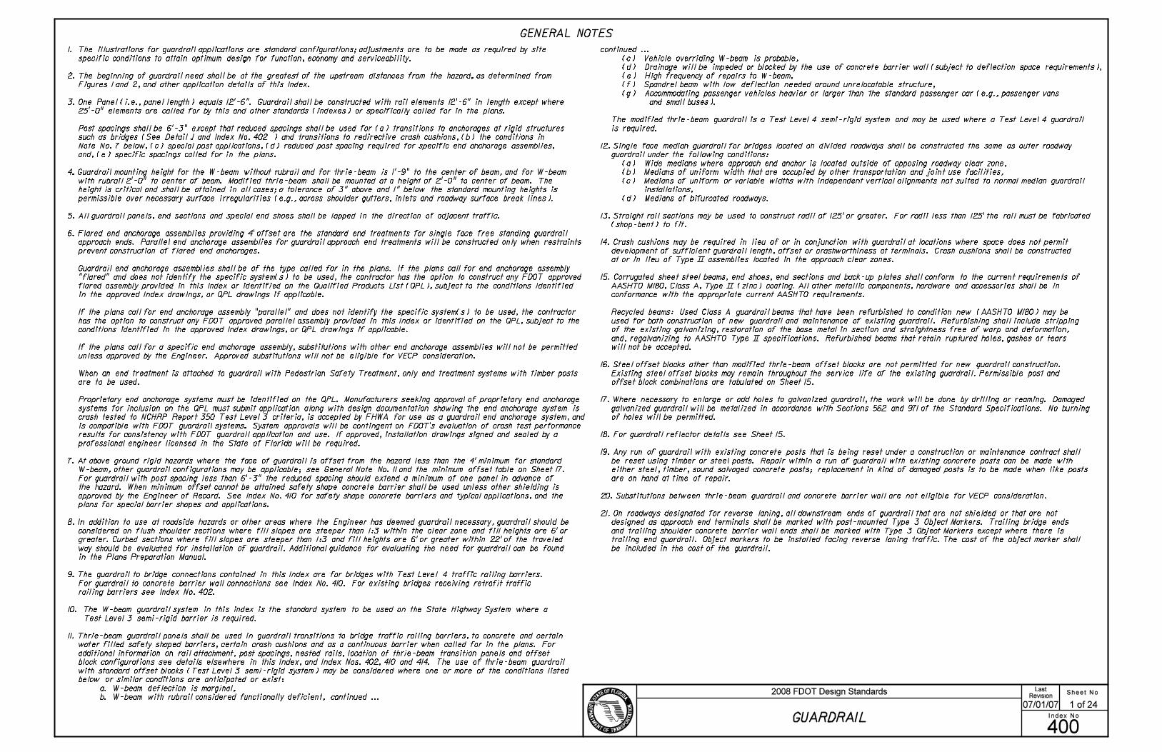
UNDIVIDED ROADWAY - DETAIL O
DIVIDED ROADWAY - DETAIL P
GUARDRAIL APPLICATIONS FOR BRIDGES WITH FULL WIDTH SHOULDERS AND
SAFETY SHAPE TRAFFIC RAILING BARRIER EXTENDING FULL LENGTH OF APPROACH SLAB
Installation When Other Hazards Or Shoulder Gutter Are Present
Installation When Other Hazards Or Shoulder Gutter Are Present
Installation For Bridge End Hazard Only (No Shoulder Gutter)
Installation For Bridge End Hazard Only (No Shoulder Gutter)
2.5 Panels
2.5 Panels
Installation When Other Hazards Or Shoulder Gutter Are Present
Installation For Bridge End Hazard Only (No Shoulder Gutter)
4 Panels W-Beam
2.5 Panels
4 Panels W-Beam
Notes For Details O & P:
Transition Section (See Detail J)
Transition Section (See Detail J)
Transition Section (See Detail J)
Transition Section (See Detail J)
Transition Section (See Detail J)
Transition Section (See Detail J)
2’
2’
2’
2’
2’
Steeper Than 1 : 3 Or Other Hazards Are Present
Steeper Than 1 : 3 Or Other Hazards Are Present
With Four Or More Lanes Trailing Guardrail Anchorages May Be As Shown In Detail P Unless Other Anchorage Called Out In The Plans
See General Notes Nos. 1, 2, 3, 4, 5, 6, 8 and 9. See Detail J for approach connections to bridges.
For end anchorage assemblies see sheets elsewhere in this Index and the plans.
Shoulder gutter in itself does not require the installation of guardrail.
Sheet No.
Index No.
2008 FDOT Design StandardsRevision
400
02
GUARDRAIL
5 of 24
Last

UNDIVIDED ROADWAY - DETAIL S
DIVIDED ROADWAY - DETAIL T
DETAIL W
Wing Post
Wing Post Wing Post
Wing Post
6.25’
6.25’ 6.26’
Projection Of NormalShoulder Line
Bridge Rail Projection
Offset Approach Slab
Exist. BridgeOffset
Bridge Rail Projection
Projection Of NormalShoulder Line
Varies
End Of Hazard
Projection Of Normal
Shoulder Line
Bridge Rail Projection
See Detail K
Bridge Rail Projection
Projection Of Normal
Shoulder Line
Approach Slab
Approach Slab Exist. Bridge
Exist. Bridge
Offset
Offset
Varies To Meet Need When Other Hazards Are Present
No Panel (s) Required In Absence Of Other Hazards
Varies To Meet Need When Other Hazards Are Present
1 Panel (See Detail W)
No Panel (s) Required In Absence Of Other Hazards
1 Panel (See Detail W)
1 Panel (See Detail W)
End Anchorage Type ~~
6.25’
6.25’ 6.25’
12.5’
12.5’
6’ (Min.)
12.48’
12.49’
For Median Guardrail See Sheets 9 & 10 And General Note 12
No Panel (s) Required In Absence Of
Other Hazards, Varies To Meet Need
When Other Hazards Are Present
See Detail K
See Detail K
Flared End
Section
STANDARD PANELS SET TO
RADIALS ADJOINING BRIDGES
UNDIVIDED ROADWAY - DETAIL H
Varies
Approach Slab
Bridge Rail Projection
Bridge
Bridge Rail Projection
Varies 4 Panels
End Of Hazard
Bridge Rail Projection
Approach Slab
Bridge
Bridge Rail Projection
Approach Slab
Approach Slab
Bridge
Approach Slab
Approach Slab
DIVIDED ROADWAY - DETAIL ~
6’ (Min.)
Varies
Varies4 Panels
End Anchorage Type ~~
End Of Hazard
Varies
For Median Guardrail See Sheets 9 & 10 And General Note 12
Flared End Section
Flared End Section
End Anchorage Type ~~
Approach End Anchorage
Assembly (Flare Shown)
Approach End Anchorage
Assembly (Flare Shown)
Approach End Anchorage
Assembly (Flare Shown)
Approach End Anchorage
Assembly (Flare Shown)Approach End Anchorage
Assembly (Flare Shown)
Approach End Anchorage
Assembly (Flare Shown)
Approach End Anchorage
Assembly (Flare Shown)
Approach End Anchorage
Assembly (Flare Shown)
Approach End Anchorage
Assembly (Flare Shown)
GUARDRAIL APPLICATIONS FOR BRIDGES WITH FULL WIDTH SHOULDERS AND
SAFETY SHAPE TRAFFIC RAILING BARRIER EXTENDING LESS THAN FULL APPROACH SLAB LENGTH
GUARDRAIL APPLICATIONS FOR BRIDGES WITH LESS THAN FULL WIDTH SHOULDERS AND
SAFETY SHAPE TRAFFIC RAILING BARRIER EXTENDING LESS THAN FULL APPROACH SLAB LENGTH
Installation For Bridge End Hazard
Only (No Shoulder Gutter)Installation For Bridge End Hazard
Only (No Shoulder Gutter)
Installation When Other Hazards Or Shoulder Gutter Are Present
Installation When Other Hazards Or Shoulder Gutter Are Present
Varies
1 Panels
Min.
Varies
1 Panels
Min.
Installation For Bridge End Hazard
Only (No Shoulder Gutter)
Notes For Details H & I:
Varies
1 Panels
Min.
Installation When Other Hazards Are Present Or Shoulder Gutter Present
See General Note No. 13
125’ R: 1 : 10 Taper Rate
187’ R: 1 : 15 Taper Rate
Varies
125’ R: 1 : 10 Taper Rate
187’ R: 1 : 15 Taper Rate
Varies
Notes for Details S & T:
Varies
125’ R: 1 : 10 Taper Rate
187’ R: 1 : 15 Taper Rate
1 Panel (See Detail W)
125’ R: 1 : 10 Taper Rate
187’ R: 1 : 15 Taper Rate
Varies
Guardrail Not Required Except Where Slope Steeper
2’
2’
2’
2’
2’
6’ (Min)
1 : 10 For Design Speeds 45 mph
1 : 15 For Design Speeds 50 mph
1 : 10 For Design Speeds 45 mph
1 : 15 For Design Speeds 50 mph
1 : 10 For Design Speeds 45 mph
1 : 15 For Design Speeds 50 mph
1 : 10 For Design Speeds 45 mph
1 : 15 For Design Speeds 50 mph
0.6
2’
0.16’5
1
4
125’ R LAYOUT
187’ R LAYOUT
0.4
2’
0.10’5
1
4
Guardrail Not Required Except Where Slope Steeper Than 1 : 3 Or Other Hazards Are Present
Than 1 : 3 Or Other Hazards Are Present
Than 1 : 3 Or Other Hazards Are Present
Guardrail Not Required Except Where Slope Steeper
For end anchorage assemblies see sheets elsewhere in this Index and in the plans.
For end anchorage assemblies see sheets elsewhere in this Index and the plans.
With Four Or More Lanes Trailing Guardrail Anchorages May Be As Shown In Detail ~ Unless Other Anchorage Called Out In The Plans
With Four Or More Lanes Trailing Guardrail Anchorages May Be As Shown In Detail ~ Unless Other Anchorage Called Out In The Plans
Shoulder gutter in itself does not require the installation of guardrail.
Transition Section
See Index No. 402
Transition Section
See Index No. 402
Transition Section
See Index No. 402
Transition Section
See Index No. 402
Transition Section
See Index No. 402
Transition Section
See Index No. 402
Transition Section
See Index No. 402
Transition Section
See Index No. 402
Transition Section
See Index No. 402
See General Notes Nos. 1, 2, 3, 4, 5, 6, 8, and 9. See Index No. 402 for approach connections to bridges.
See General Notes Nos. 1, 2, 3, 4, 5, 6, 8 and 9. See Index No. 402 for approach connections to bridges.
Sheet No.
Index No.
2008 FDOT Design StandardsRevision
400
07/01/07
GUARDRAIL
6 of 24
Last

Bridge
Approach Slab
Slope Varies
Shoulder Line
Median
Slope Varies
Shoulder LineSee DETAIL J
Break PointGuardrail
10’ Min.
WHEN END TERMINAL CANNOT BE LOCATED OUTSIDE OF OPPOSING ROADWAY CLEAR ZONE
Extended Shoulder
Misc. Asph. Pavt. To Suit
Shoulder Treatment
Extended Shoulder Not
See DETAIL J
30^
| Median
Break Point
Guardrail
Approach SlabBridge
For Guardrail Lengths See Table Below
Uniform Slope
10’ Min.
Misc. Asph. Pavt. To Suit
Shoulder Treatment
Approach SlabBridge
Median
Shoulder Line
Shoulder Line
(See Detail W)
125’ R: 1 : 10 Taper Rate
187’ R: 1 : 15 Taper Rate
15^ or Flatter
WHEN END TERMINAL IS OUTSIDE OF OPPOSING ROADWAY CLEAR ZONE
Cle
ar Z
one W
idth
Extended Shoulder Not
Back Rail (To Be Paid
For As Guardrail, LF)
Departure Line (Location And Rate Varies, See Sheet No. 2) Crash Cushion
C. C.Extended Shoulder
Extended Shoulder
Shoulder Transition(Extended Shoulder)
Shoulder Transition(Extended Shoulder)
Panels (No.)
Front Back Total Total
Panels (No.)
Front Back Total Total TotalFront Back Total
Panels (No.)
GUARDRAIL LENGTHS
Width
Median
Front Back Total
Panels (No.)
Total
1: 10 TAPER RATE 1: 15 TAPER RATE
9.5
10.5
10.5
11.5
12.5
13.5
14.5
14.5
15.5
6
7
7
8
9
9
10
10
11
15.5
17.5
17.5
19.5
21.5
22.5
24.5
24.5
26.5 331.25
6.5
7.5
7.5
8.5
9.5
10.5
10.5
11.5
12.5
4
5
5
6
6
7
7
8
9
10.5
12.5
12.5
14.5
15.5
17.5
17.5
19.5
21.5
13.5
14.5
15.5
16.5
17.5
19.5
20.5
21.5
22.5
10
11
12
13
13
15
16
17
17
23.5
25.5
27.5
29.5
30.5
34.5
36.5
38.5
39.5
343.75
368.75
381.25
431.25
456.25
481.25
493.75
8.5
9.5
10.5
11.5
13.5
14.5
15.5
16.5
17.5
6
7
8
9
11
11
12
13
13
14.5
16.5
18.5
20.5
24.5
25.5
27.5
29.5
30.5
343.75
368.75
381.25
APPROACH GUARDRAIL TREATMENTS FOR BRIDGES WITH SAFETY SHAPE TRAFFIC RAILING
EXTENDING FULL APPROACH SLAB LENGTH IN WIDE MEDIANS WITH FLUSH SHOULDERS
Design
SpeedProjected
ADT
Urban / Curb
356.5
Remarks
55
55
45-50
45-50
35-40
45-50 Urban / Curb
1500
1500
1500
1500
1500
1500w
wo
o
306.5
10’ & 12’ Rdwy. Shldr.
GuardrailLength
GuardrailLength(mph)
Min.MedianWidth
Min.MedianWidth
(See Detail W)
125’ R: 1 : 10 Taper Rate
187’ R: 1 : 15 Taper Rate
Transition Section
Transition Section
Approach End Anchorage Assembly
6’ Or 10’ Shoulder (Std.)
2’
1 : 10 For Design Speeds 45 mph
1 : 15 For Design Speeds 50 mph
1 : 25 When Shoulder Gutter Present
1 : 15 For Design Speeds 50 mph
6’ Or 10’ Shoulder (Std.)
2’
CZ
(Ft.)
6’ & 8’ Rdwy. Shldr.
GUARDRAIL LENGTH (Ft.)
60-70
60-70
36
30
30
24
24
20
281.5
194.0
144.0
144.0
144.0
219.0
219.0
50
(Ft.)
6’ Bridge Shoulder 10’ Bridge Shoulder
Length (Ft.) Length (Ft.)
6’ Bridge Shoulder 10’ Bridge Shoulder
Length (Ft.) Length (Ft.)
32
34
36
38
40
42
44
46
48
193.75
218.75
218.75
243.75
268.75
281.25
306.25
306.25
131.25
156.25
156.25
181.25
193.75
218.75
218.75
243.75
268.75
293.75
318.75
181.25
206.25
231.25
256.25
306.25
318.75
24
18
44
44
38
38
34
38
32
54
48
48
42
42
38
42
36
1 : 10 For Design Speeds 45 mph
Steeper Than 1 : 10
Steeper Than 1 : 10
Flared End Section
281.5
194.0
144.0
144.0
For Guardrail Lengths See Table Below Left
Note: For approach end anchorage assemblies see sheets elsewhere in this Index and the plans.
The lengths shown on this table are typical for roadways with standard width shoulders. Length requirements shall be determined on a site
specific basis for both standard width and narrow bridge shoulders and end anchorage or end shielding use.
194.0
94.0
81.5
Lengths are based on minimum median widths and on standard
clear zone widths for travel lanes on tangent roadways, and
the length of advancement needed for flared end anchorage
assemblies to shield normal transverse underslope and bridge
end hazards. Lengths may need to be adjusted for auxiliary
lanes, curved roadways, parallel end anchorage assemblies,
skewed crossings and other hazards present.
5’ Misc. Asphalt Pavt.
5’ Misc. Asphalt Pavt.
Edge Of Travel Lane
Edge Of Travel Lane
Edge Of Traffic Lane
Edge Of Traffic Lane
Sheet No.
Index No.
2008 FDOT Design StandardsRevision
400
00
GUARDRAIL
7 of 24
Last
Guardrail Transition (For Transition Details See QPL VendorDrawings For Individual Crash Cushion Used)

Bridge
10’ Min.
Misc. Asphalt
Shoulder Line
Shoulder Line
Approach Slab
Shoulder Line
Shoulder Line
10’ Min.
12’10
’1
0’
12’
10
’
| Median
| MedianMisc. Asphalt
Guardrail Panels And Length (See Table Below)
Guardrail Panels And Length (See Table Below)
125’ R: 1 : 10 Taper Rate
Guardrail (See Sheet 7)
Guardrail (See Sheet 7)
C. C. Media
n
C. C.
Media
n
Note: The guardrail configurations shown apply only to parallel or near parallel bridges with open medians.
x
Edge Of Traffic Lane
Point Of Impact Speed (S )~
Speed (S ) For Determining Crash Cushion Size:~
S = (Design Speed)x
L~
Departure Line
Guardrail Transition (Approach Section)
As Required For Redirective Crash Cushion
Guardrail Transition (Approach Section)
As Required For Redirective Crash Cushion
SIZING CRASH CUSHIONS LOCATED
ON OPPOSING ROADWAY SHOULDERS
L (Runout Length)
1: 10 TAPER RATE 1: 15 TAPER RATE
PANELS (No.) PANELS (No.)
1: 10 TAPER RATE 1: 15 TAPER RATE
PANELS (No.) PANELS (No.)
GUARDRAIL LENGTHS
~ ~
C. C.
Crash Cushion Located On
Opposing Roadway Shoulder
See DETAIL J
Approach SlabBridge
Approach Slab
Bridge
10
’
See DETAIL J
Approach SlabBridge
(See Detail W)
125’ R: 1 : 10 Taper Rate
187’ R: 1 : 15 Taper Rate
9.5
11.5
12.5
14.5
13.5
15.5
18.5
20.5 7.5
6.5
5.5*
5.5*
10.5
8.5
6.5
5.5*
Guardrail Length-One Half Panel Less Than Taper Side For Plan Quantities
Guardrail Length-One Half Panel Less Than Taper Side For Plan Quantities
APPROACH GUARDRAIL TREATMENTS FOR BRIDGES WITH SAFETY SHAPE TRAFFIC RAILING
EXTENDING FULL APPROACH SLAB LENGTH IN NARROW MEDIANS WITH FLUSH SHOULDERS
Transition Section
d
= Design SpeedCZ
(CZ-d)
Cle
ar
Zone W
idth
(C
Z)
Transition Section
187’ R: 1 : 15 Taper Rate (See Detail W)
1 : 10 For Design Speeds 45 mph
1 : 15 For Design Speeds 50 mph
MEDIANS WITH 10’ BRIDGE SHOULDERS
4’
8’
8’
4’
1 : 10 For Design Speeds 45 mph
1 : 15 For Design Speeds 50 mph
6’
MEDIANS WITH 6’ BRIDGE SHOULDERS
6’
6’
MEDIAN
WIDTH
(Ft.) LENGTH (Ft.) LENGTH (Ft.) LENGTH (Ft.) LENGTH (Ft.)
30
28
26
24
181.25
156.25
143.75
118.75
256.25
231.25
193.75
168.75
93.75
81.25
68.75
68.75
131.25
106.25
81.25
68.75
6’ BRIDGE SHOULDERS 10’ BRIDGE SHOULDERS
The lengths shown in this table are based on standard widths for roadway and bridge median shoulders. Length requirements for
both standard width and narrow bridge shoulders and end anchorage or end shielding requirements shall be determined on a site
specific basis. When crash cushions are required on opposing roadway shoulders, their sizes may be determined by the residual
speeds (S ’s) along the runouts from the approach roadways; however, when calculated speeds (S ’s) are less than 30 mph;
crash cushions shall be no less in size than for 30 mph, see speed diagram left. The number of panels may be reduced when
installing a crash cushion more than 2.5’ in width, see * below.
* Number shown is the minimum number of panels plus a W-Thrie beam transition panel; single faced guardrail must have a length
of five (5) or more panels.
Misc. Asphalt Pavt.
Misc. Asphalt Pavt.
Edge Of Traffic Lane
Edge Of Traffic Lane
Edge Of Traffic Lane
Edge Of Traffic Lane
Crash Cushion
Crash Cushion
Sheet No.
Index No.
2008 FDOT Design StandardsRevision
400
07/01/07
GUARDRAIL
8 of 24
Last

Bridge
Approach Slab
Slope Varies
Shoulder Line
Median
Slope Varies
Shoulder Line
Break Point
Guardrail
10’ Min.For Guardrail Lengths See Table Below
Panels (No.)
Front Back Total
3
4
5
6
6
6
7
8
9
Total
Panels (No.)
Front Back Total
9
10
11
12
13
14
15
16
16
Total TotalFront Back Total
368.75
393.75
418.75
6
6
7
9
9
10
11
12
13
Panels (No.)
GUARDRAIL LENGTHS
Width
Median
Front Back Total
Panels (No.)
6
6
7
8
8
8
9
9
11
Total
1: 10 TAPER RATE 1: 15 TAPER RATE
443.75
456.25 368.75
WHEN END TERMINAL CANNOT BE LOCATED OUTSIDE OF OPPOSING ROADWAY CLEAR ZONE
Extended Shoulder
Misc. Asph. Pavt. To Suit
Shoulder Treatment
Extended Shoulder Not
30^
| Median
Break Point
Guardrail
Approach Slab
Bridge
For Guardrail Lengths See Table Below
Uniform Slope
10’ Min.
Misc. Asph. Pavt. To Suit
Shoulder Treatment
Approach SlabBridge
Median
Shoulder Line
Shoulder Line
(See Detail W)
125’ R: 1 : 10 Taper Rate
187’ R: 1 : 15 Taper Rate
15^ or Flatter
WHEN END TERMINAL IS OUTSIDE OF OPPOSING ROADWAY CLEAR ZONE
Cle
ar Z
one W
idth
Extended Shoulder Not
Back Rail (To Be Paid
For As Guardrail, LF)
Departure Line (Location And Rate Varies, See Sheet No. 2) Crash Cushion
C. C.Extended Shoulder
Extended Shoulder
Shoulder Transition(Extended Shoulder)
Shoulder Transition(Extended Shoulder)
APPROACH GUARDRAIL TREATMENTS FOR BRIDGES WITH SAFETY SHAPE TRAFFIC RAILING
EXTENDING LESS THAN FULL APPROACH SLAB LENGTH IN WIDE MEDIANS WITH FLUSH SHOULDERS
Design
SpeedProjected
ADT
Urban / Curb
362.5
Remarks
55
55
45-50
30-40
Urban / Curb
1500
1500
1500
1500
1500
1500w
wo
o
312.5
10’ & 12’ Rdwy. Shldr.
GuardrailLength
GuardrailLength(mph)
Min.MedianWidth
Min.MedianWidth
Transition Section
(See Detail W)
125’ R: 1 : 10 Taper Rate
187’ R: 1 : 15 Taper Rate
Transition Section
7.5
8.5
9.5
10.5
10.5
11.5
12.5
12.5
13.5
14.5
16.5
18.5
18.5
19.5
21.5
21.5
25.5
5.5
6.5
7.5
7.5
8.5
9.5
10.5
11.5
11.5
12.5
13.5
14.5
16.5
17.5
18.5
19.5
20.5
20.5
22.5
24.5
26.5
29.5
31.5
33.5
35.5
36.5
7.5
7.5
8.5
10.5
11.5
12.5
13.5
14.5
16.5
13.5
13.5
15.5
19.5
20.5
22.5
24.5
26.5
29.5
7.5
9.5
11.5
13.5
13.5
14.5
16.5
18.5
20.514.5
4.5
331.25
331.25
Approach End Anchorage Assembly
6’ Or 10’ Shoulder (Std.)
2’
1 : 10 For Design Speeds 45 mph
1 : 15 For Design Speeds 50 mph
1 : 25 When Shoulder Gutter Present
GUARDRAIL LENGTH (Ft.)
6’ & 8’ Rdwy. Shldr.CZ
(Ft.)
60-70
60-70
45-50
45-50
36
30
30
24
24
20
24
18
50
44
44
38
38
34
38
32
54
48
48
42
42
38
42
36
287.5
287.5
212.5
212.5
162.5
212.5
162.5
237.5
237.5
162.5
162.5
112.5
162.5
100.0
6’ Or 10’ Shoulder (Std.)
2’
1 : 10 For Design Speeds 45 mph
1 : 15 For Design Speeds 50 mph
(Ft.)
6’ Bridge Shoulder 10’ Bridge Shoulder
Length (Ft.) Length (Ft.)
6’ Bridge Shoulder 10’ Bridge Shoulder
Length (Ft.)Length (Ft.)
32
34
36
38
40
42
44
46
48
168.75
181.25
206.25
231.25
231.25
243.75
268.75
268.75
318.75
93.75
118.75
143.75
168.75
168.75
181.25
206.25
231.25
256.25
256.25
281.25
306.25
168.75
168.75
193.75
243.75
256.25
281.25
306.25
Steeper Than 1 : 10
Steeper Than 1 : 10Flared End Section
Note: For approach end anchorage assemblies see sheets elsewhere in this Index and the plans.
5’ Misc. Asphalt Pavt.
5’ Misc. Asphalt Pavt.
See Index No. 402
Index No. 402
The lengths shown on this table are typical for roadways with standard width shoulders and a relocated connection to the existing wing post.
When the wing post is replaced by bridge traffic railing barrier, reference Detail J and see Index No. 402. Length requirements shall be
determined on a site specific basis for both standard width and narrow bridge shoulders and for end anchorage or end shielding use.
Lengths are based on minimum median widths and on
standard clear zone widths for travel lanes on tangent
roadways, and the length of advancement needed for
flared end anchorage assemblies to shield normal
transverse underslope and bridge end hazards. Lengths
may need to be adjusted for connection location on
wing post or bridge traffic railing barrier (see Index
No. 402), auxiliary lanes, curved roadways, parallel end
anchorage assemblies, skewed crossings and other
hazards present. When the wing post is replaced by
bridge traffic railing barrier, reference Detail J and see
Index No. 402.
Edge Of Travel Lane
Edge Of Travel Lane
Edge Of Traffic Lane
Edge Of Traffic Lane
Sheet No.
Index No.
2008 FDOT Design StandardsRevision
400
04
GUARDRAIL
9 of 24
Last
Guardrail Transition (For Transition Details See QPL VendorDrawings For Individual Crash Cushion Used)

Bridge
Bridge
Bridge
Bridge
10’ Min.
Special Blocks As Required
Approach Slab
Guardrail Panels And Lengths Same As Taper Side For Plan Quantities
Shoulder Line
Shoulder Line
Approach Slab
Shoulder Line
Shoulder Line
10’ Min.
Guardrail Panels And Lengths Same As Taper Side For Plan Quantities
12’10
’1
0’ 12’
10
’1
0’
Special Blocks As Required
| Median
| MedianMisc. Asphalt
Guardrail Panels And Length (See Table Below)
Guardrail Panels And Length (See Table Below)
125’ R: 1 : 10 Taper Rate
125’ R: 1 : 10 Taper Rate
Guardrail (See Sheet 9)
Guardrail (See Sheet 9)
C. C. Media
n
C. C.
Media
n
Note: The guardrail configurations shown apply only to parallel or near parallel bridges with open medians.
x
Edge Of Traffic Lane
Point Of Impact Speed (S )~
Speed (S ) For Determining Crash Cushion Size:~
S = (Design Speed)x
L~
Departure Line
Guardrail Transition (Approach Section)
As Required For Redirective Crash Cushion
Guardrail Transition (Approach Section)
As Required For Redirective Crash Cushion
SIZING CRASH CUSHIONS LOCATED
ON OPPOSING ROADWAY SHOULDERS
L (Runout Length)
PANELS (No.) PANELS (No.)PANELS (No.) PANELS (No.)
GUARDRAIL LENGTHS
~ ~
C. C.
Crash Cushion Located On
Opposing Roadway Shoulder
APPROACH GUARDRAIL TREATMENTS FOR BRIDGES WITH SAFETY SHAPE TRAFFIC RAILING
EXTENDING LESS THAN FULL APPROACH SLAB LENGTH IN NARROW MEDIANS WITH FLUSH SHOULDERS
Transition Section
Transition Section
12.5
11.5
9.5
8.5
18.5
16.5
14.5
11.5
6.5
5.5
5.5*
5.5*
9.5
7.5
5.5*
5.5*
d
= Design SpeedCZ
(CZ-d)
Cle
ar Z
on
e W
idth
(C
Z)
187’ R: 1 : 15 Taper Rate (See Detail W)
1 : 15 For Design Speeds 50 mph
1 : 10 For Design Speeds 45 mph
MEDIANS WITH 10’ BRIDGE SHOULDERS
4’
8’
4’
8’
MEDIANS WITH 6’ BRIDGE SHOULDERS
1 : 10 For Design Speeds 45 mph
1 : 15 For Design Speeds 50 mph
6’
6’
6’
187’ R: 1 : 15 Taper Rate (See Detail W)
MEDIAN
WIDTH
(Ft.) LENGTH (Ft.) LENGTH (Ft.) LENGTH (Ft.) LENGTH (Ft.)
30
28
26
24
156.25
143.75
118.75
106.25
231.25
206.25
181.25
143.75
81.25
68.75
68.75
68.75 68.75
68.75
93.75
118.75
1 : 10 TAPER RATE 1 : 15 TAPER RATE 1 : 10 TAPER RATE 1 : 15 TAPER RATE
6’ BRIDGE SHOULDERS 10’ BRIDGE SHOULDERS
The lengths shown in this table are based on standard widths for roadway and bridge median shoulders. Length requirements for
both standard width and narrow bridge shoulders and end anchorage or end shielding requirements shall be determined on a site
specific basis. When crash cushions are required on opposing roadway shoulders, their sizes may be determined by the residual
speeds (S ’s) along the runouts from the approach roadways; however, when calculated speeds (S ’s) are less than 30 mph crash
cushions shall be no less in size than for 30 mph; see speed diagram left. The number of panels may be reduced when installing
a crash cushion more than 2.5’ in width; see * below.
*Number shown is the minimum number of panels plus a W-Thrie beam transition panel; single faced guardrail must have a length
of five (5) or more panels.
Misc. Asphalt Pavt.
Misc. Asphalt Pavt.
Misc. Asphalt Pavt.
See Index No. 402
See Index No. 402
Edge Of Traffic Lane
Edge Of Traffic Lane
Edge Of Traffic Lane
Edge Of Traffic Lane
Sheet No.
Index No.
2008 FDOT Design StandardsRevision
400
04
GUARDRAIL
10 of 24
Last
Crash Cushion
Crash Cushion

Taper.
on intersecting drive or side road adjoins the project.
Radial guardrail to be installed when guardrail required
Guardrail installation limited to roadway right of way
unless otherwise called for in the plans.
2
1
3
4
5
R1
R2
LEGEND
1
2
TAPER TURNOUTS SIMPLE CURVE TURNOUTS
RADIAL GUARDRAIL
6
7
8
9
10
11
12
13
GUARDRAIL APPLICATIONS FOR INTERSECTING DRIVES AND SIDE ROADS ON RURAL FACILITIES
on the intersecting drive or side road (radius R ).
Pavement return (radius R ).
3
11
9
2 2
1
3
3
5
4
1
4
5
Intersecting Drive
Or Side Road
1 1
PC or PT PC or PTRoadway
Varies
Intersecting Drive
Or Side RoadVaries
PC or PT PC or PT
3
3
4 46
68 8
9
10
9
11
11 1212
13 13
7
8
9 9
10
1111
12 12
13 13
End anchorage Type ~~ (radial return only).
Roadway
Note:
Post for locating flare, proximate to PC or PT:
Post for locating flare, proximate to PC or PT:
Flared end anchorage to be installed except when existing guardrail
Where openings in guardrail are required in close proximity to bridge traffic
rails or ends of concrete barrier walls, and minimum length guardrail with
flared end anchorages can not be applied, either controlled release returns
or energy absorbing terminals are to be applied.
The guardrail application shown on this sheet are for highways with flush
shoulders and no restraints for constructing flared end anchorages and minimum
lengths of guardrail. For highways with flush shoulders and restraints to
constructing flared anchorages, see General Note No. 6.
Shoulder in absence of guardrail.
Expanded shoulder for guardrail.
7
107
77
7
10
7
7
8
7
Expanded shoulder for flared guardrail end anchorage.
Flared end anchorage assembly.
Normal Turnouts
Simple CurveTaper
Panels
Required
15’
20’
25’
30’
35’
40’
45’
50’
25’
25’
25’
25’
25’
40’
40’
40’
3
3
3
3
3
5
5
5
85 56’
85 56’
85 56’
85 56’
85 56’
89 31’
89 31’
89 31’
25’
25’
25’
25’
25’
40’
40’
40’
3
3
3
3
3
5
5
5
Panels
RequiredR
Note: Only 25’ and 40’ radius panels are to be used
2R1R2
RADIAL GUARDRAIL
85 56’
85 56’
85 56’
85 56’
85 56’
89 31’
89 31’
89 31’
for return guardrail on normal turnouts. On
skewed turnouts the number of panels used
and their arrangement with straight panels
will be as shown in the plans or as directed
by the Engineer. No. 2 post for Radii 25’ or less.
No. 3 post for Radii 25’ and 50’.
Between No. 4 and No. 5 posts for Radii 50’ or greater.
No. 3 post for Radii 25’ or less.
Between No. 4 and No. 5 posts for Radii greater than 25’.
Edge of traffic lane for simple curve turnouts.
Edge of travel lane for taper turnouts.
Sheet No.
Index No.
2008 FDOT Design StandardsRevision
400
04
GUARDRAIL
11 of 24
Last

Shoulder Gutter Misc. Asphalt Pavt.
Misc. Asphalt Pavt.
2’-4"
0.06
0.06
GUARDRAIL TRANSITION NOTE
Misc. Asphalt Pavt.
0.06
2"
SPECIAL GALVANIZED STEEL FILLER PLATE
FOR USE AT SECTION BB
12’-6" Nested
Arc
ELEVATION
6’-3" Typical
Shoulder Gutter
W-Thrie Beam
Transition Section
Misc. Asphalt Pavt.
Direction Of Travel
(a) (b) (c) (d) (e) (f) (g) (h)
Approach Slab
Shoulder Break Point
0.02 (Std.)
6" Dike
W-Thrie Beam
Transition Section
PLAN - GUARDRAIL, SHOULDER GUTTER AND SHOULDER TRANSITIONS
43’-9" Guardrail Transition
Standard W-Beam Guardrail,
End Anchorage Assembly,
Special Transition Or
Other Special Treatment
Thrie-Beam Terminal
Connector
Approach Slab And Bridge Traffic Railing Barrier
End Shoulder Gutter
Transition With Dike
Begin Shoulder
Gutter Transition
0.06 (Std.)0.06 (Std.)
SECTION AA SECTION BB SECTION CC SECTION DD
SECTION EE SECTION FF SECTION GG
GUARDRAIL APPROACH TRANSITION AND CONNECTION FOR BRIDGES WITH SAFETY SHAPE
TRAFFIC RAILING BARRIERS EXTENDING FULL LENGTH OF APPROACH SLAB
DETAIL J
12’-6" Thrie-Beam Panel
3’
12’-6" 12’-6" Thrie-Beam Panel (Nested)
25’ Thrie-Beam Panel
3’
25’ Shoulder Gutter Transition (Shoulder Gutter To Gutter With Dike)
2’
7’-6"
3’-6" 4’
6"
3’
1’-
9"
7’-6"
4’
3’
7’-6"
6"7"
1’-
9"
4"
8"
8"
All Holes Are 1" \
End Measurement For Guardrail Payment
1’ - 1 1/2 "
6 @ 1’-6 3/4 " cc 3 @ 3’-1 1/2 " cc
5/8 " \!18.5" Long Upper And
17.5" Long Lower Post Bolt
And Nut With 1 3/4 " OD Steel
Washers Under Nuts
5/8 " \!20" Long Upper And
19" Long Lower Post Bolt
And Nut With 1 3/4 " OD Steel
Washers Under Nuts
3’-7 3/8 "
21"!12"! 5/8 " Thrie-Beam
Terminal Connector Plate
8"!8"!1 1/4 " Special
Galvanized Steel Filler Plate
3 13/16 "
1 1/2 "
1 1/4 "
Back
Contoured
Back
Contoured
22
"
22
"
19 3
/4 "
19 3
/4 "
X Y ZV WU
U
V
W
X
Y
Z
6 1/8 " 4 1/8 " 3 5/8 " 5 1/2 " nom. 5" nom.7 1/2 " nom.
5 1/8 " 3 1/8 " 2 5/8 " 6 1/2 " nom. 4 1/2 " nom. 4" nom.
4 3/8 " 2 3/8 " 1 7/8 "Double Face Guardrail With Steel Posts
Double Face Guardrail With Timber Posts
5 3/4 " 3 3/4 " 3 1/4 "
APPLICATIONS
THRIE-BEAM OFFSET BLOCKS FIELD TRIMMED FOR USE AT SECTIONS CC & DD
When shoulder gutter is required, the 25’ long dike transition, shown in the ’PLAN’
and ’PICTORIAL’ above, is required. Double offset blocks are shown for guardrail
installations adjacent to shoulder gutter/dike transitions; single offset blocks shall be
installed in absence of shoulder gutter. Nested rails shall not be bolted to the blocks
and posts at posts (a), (c), and (e). One 16d galvanized nail shall be driven between
each post and block, and between double blocks, in order to prevent block rotation,
see ’16d NAIL FOR PREVENTION OF OFFSET BLOCK ROTATION’, this Index.
BLOCK FOR
SECTION CC
BLOCK FOR
SECTION DD
Single Face Guardrail
SECTION CC SECTION DD
For Double Face Guardrail Connections To Median Bridge Traffic Railing Barrier,
See Index No. 410 ’Guardrail Connection To Concrete Barrier Wall Approach Ends’.
Guardrail Transition And Connection Cost To Be Included In The Contract Price For The Approaching
Guardrail System; No Additional Payment For Guardrail Bridge Anchorage Assembly, Thrie-Beam Panels,
Nested Panels, W-Thrie Beam Transition Panel, Back Up Plate, Filler Plate And Accessories.
A
A
B
B
C
C
D
D
E
E F
F G
G
21"!12"! 5/8 " Thrie-Beam Terminal
Connector Plate (Back-Up Plate) and
8"!8"!1 1/4 " Special Galvanized Steel
Filler Plate (See Below)
7/8 " \!15" Long HS Hex Bolts (3 1/2 "
Min. Thread Length) And Nuts (5 Reqd.)
With 2 1/4 " OD Plain Round
Washers Under Heads And Nuts
For Other Flare Offsets And Parallel Alignments See Sheets Nos. 5, 6, 7 and 8
Direction O
f Travel
Guardrail O
mitted From
View
DIKE TRANSITION PICTORIAL
0.06 (S
td.)
0.02 (S
td.)
25’ Shoulder Gutter Transition
(Shoulder Gutter To G
utter With D
ike)
Shoulder Gutter
3’
4"
Near Edge O
f Traffic Lane
Edge Of Traffic Lane
1’-6"
Standard
Shoulder
Line
See Index Nos. 420, 422, 423, 424, 425, and 5210 For Barrier End Details
Sheet No.
Index No.
2008 FDOT Design StandardsRevision
400
07/01/07 12 of 24
Last
Sand-Cement Protection
15’
12"
Bridge
Bridge Traffic Railing Barrier
Wing Wall
45^
Bridge
Bridge Traffic Railing Barrier
Wing Wall
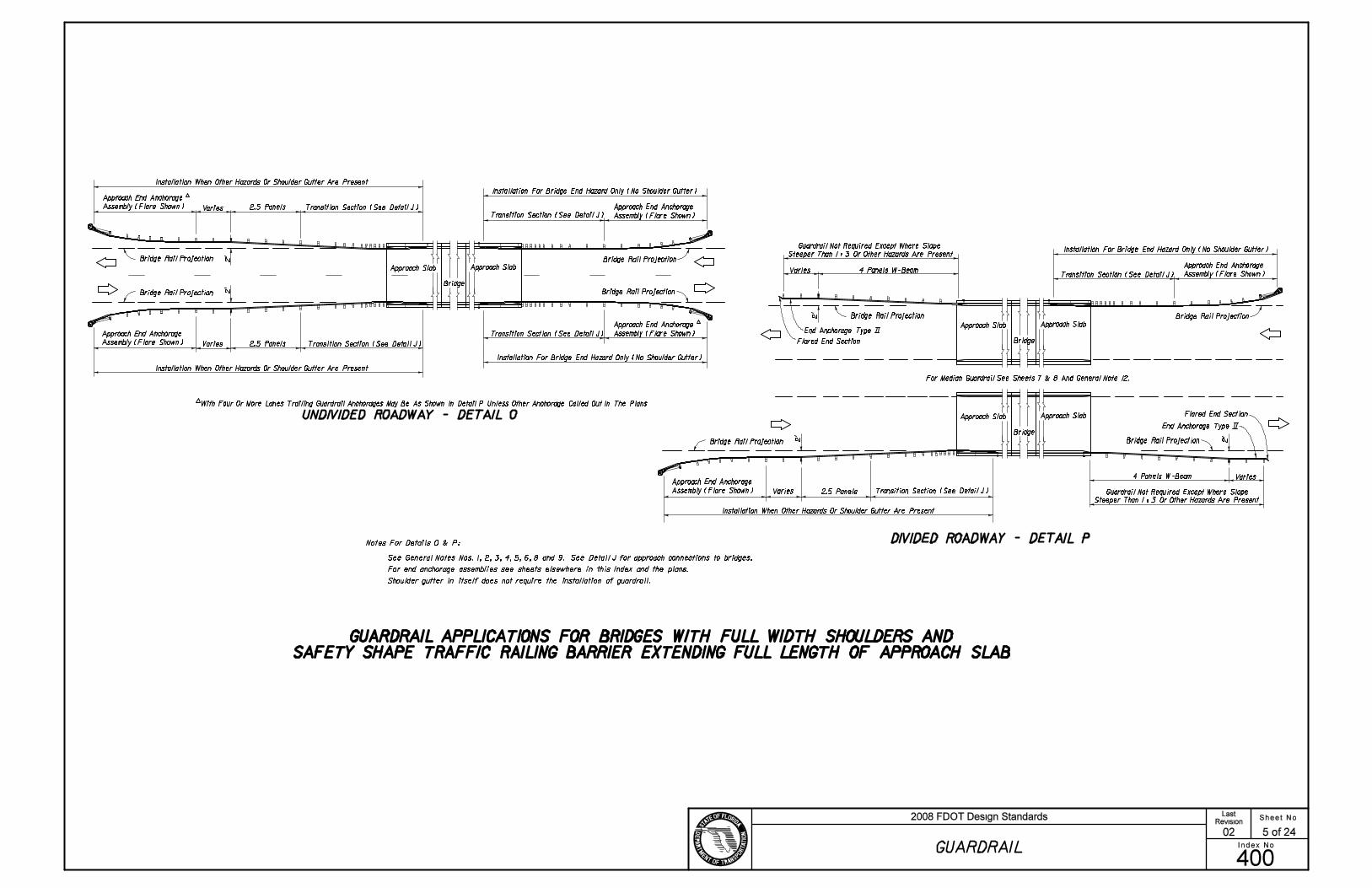
SKETCHES - BRIDGES WITH SAFETY SHAPE TRAFFIC RAILING BARRIER
EXTENDING LESS THAN FULL APPROACH SLAB LENGTH
Varies (15’ Min.)
SKETCHES - BRIDGES WITH SAFETY SHAPE TRAFFIC RAILING BARRIER EXTENDING FULL APPROACH SLAB LENGTH
SKETCH NOTES
For Additional Guardrail Information See Sheet 12
Limit Of Slope Pavement At Roadways
And Sand Cement Protection At Railroads
Rubble Protection (Sand-Cement Protection When Specified)Rubble Protection (Sand-Cement Protection When Specified)
BRIDGES OVER STREAMS
BRIDGES OVER RAILROADS
BRIDGES OVER STREAMS
BRIDGES OVER ROADWAYS OR RAILROADS
1’-6" R (Min.)
30’ Approach Slab With Bridge Traffic Railing Barrier
30’ Approach Slab With Bridge Traffic Railing Barrier
SHOULDER INTERFACE BETWEEN ROADWAYS AND BRIDGES
1. These sketches are for showing shoulder interface between roadways and bridges where crossings are normal to other
roadways, railroads and streams. For site specific applications and details see the plans and the FDOT Structures Design
Office "Detailing Manual" and "Design Guidelines".
2. Shoulder treatments shown in these sketches are for locations with shoulder gutter; shoulder hinge location will vary for
facilities without shoulder gutter.
For Additional Information See Index No. 402
Sheet No.
Index No.
2008 FDOT Design StandardsRevision
400
04
GUARDRAIL
13 of 24
Last
CB
CB
A
A
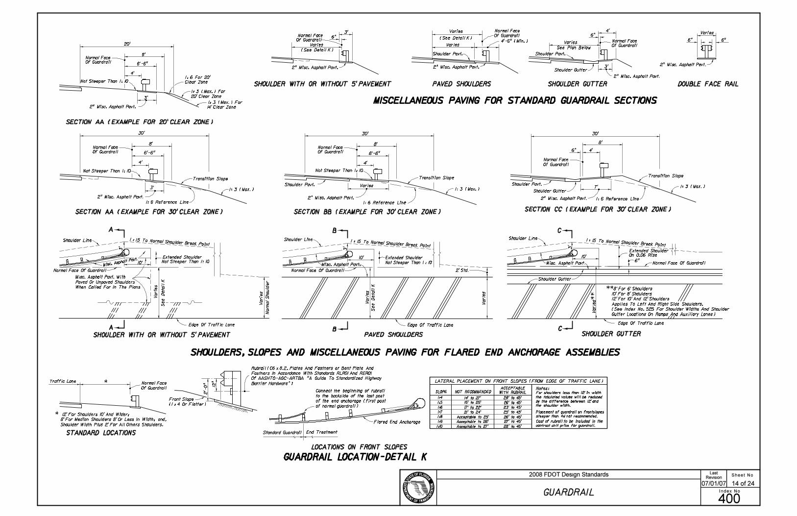
PAVED SHOULDERS
PAVED SHOULDERS
Of Guardrail
Varies20’
Clear Zone
20’ Clear Zone
30’
Normal Face
Shoulder Pavt.
Varies
30’
Extended Shoulder
2’ Std.
Shoulder Pavt.
Normal Face
Of Guardrail
Of Guardrail
Of Guardrail
Extended Shoulder
Misc. Asphalt Pavt.V
ari
es
Vari
es
Vari
es
Normal Face
Of Guardrail
30’
Extended Shoulder
Varies
Varies
Varies
Normal Face
Of Guardrail
Shoulder Gutter
Shoulder Gutter
Shoulder Pavt.
Shoulder Gutter
Of Guardrail
Shoulder Pavt.Normal Face
Normal Face
SHOULDER GUTTER
Norm
al
Should
er
SHOULDER GUTTER DOUBLE FACE RAIL
(See Detail K)
Not Steeper Than 1: 10
Not Steeper Than 1: 10
Not Steeper Than 1: 10
GUARDRAIL LOCATION-DETAIL K
On 0.06 Rise
Normal Face
12
"
LOCATIONS ON FRONT SLOPES
Normal Face Of Guardrail Normal Face Of Guardrail
Normal Face
Of Guardrail
Traffic Lane
STANDARD LOCATIONS
*
Vari
es
See D
eta
il K
See D
eta
il K
Varie
s*
*
Varies
See Plan Below
1: 6 For 20’
14’ Clear Zone
SECTION AA (EXAMPLE FOR 20’ CLEAR ZONE)
SECTION AA (EXAMPLE FOR 30’ CLEAR ZONE) SECTION BB (EXAMPLE FOR 30’ CLEAR ZONE)SECTION CC (EXAMPLE FOR 30’ CLEAR ZONE)
1: 6 Reference Line
1: 3 (Max.) For
1: 3 (Max.) For
1: 3 (Max.)
1: 6 Reference Line1: 6 Reference Line
1: 3 (Max.) 1: 3 (Max.)
Normal Face Of Guardrail
Not Steeper Than 1: 10
Shoulder Line
10’
Misc. Asphalt Pavt. With
Paved Or Unpaved Shoulders
When Called For In The Plans
(See Detail K)
Transition Slope Transition SlopeTransition Slope
SHOULDERS, SLOPES AND MISCELLANEOUS PAVING FOR FLARED END ANCHORAGE ASSEMBLIES
Shoulder Line
10’
Shoulder Line
10’
1 : 15 To Normal Shoulder Break Point1 : 15 To Normal Shoulder Break Point
1 : 15 To Normal Shoulder Break Point
MISCELLANEOUS PAVING FOR STANDARD GUARDRAIL SECTIONS
Front Slope
(1 : 4 Or Flatter)
Flared End Anchorage
6" 6"
6"
4’
3’
4’-6" (Min.)
3’
6"
SHOULDER WITH OR WITHOUT 5’ PAVEMENT
8’
6’-6"
4’
3’
8’
6’-6"
4’
3’
8’
6’-6"
4’
8’
4’6"
7’
6"
3’
3’
Not Steeper Than 1 : 10
3’
SHOULDER WITH OR WITHOUT 5’ PAVEMENT
* 12’ For Shoulders 10’ And Wider;
8’ For Median Shoulders 8’ Or Less In Width; and,
Shoulder Width Plus 2’ For All Others Shoulders.
2’-0
"
Rubrail (C6!8.2, Plates And Fastners or Bent Plate And
Fastners In Accordance With Standards RLR01 And RER01
Of AASHTO-AGC-ARTBA "A Guide To Standardized Highway
Barrier Hardware")
SLOPE
Acceptable to 25’
Acceptable to 26’
Acceptable to 27’
NOT RECOMMENDED For shoulders less than 12’ in width
the tabulated values will be reduced
by the difference between 12’ and
the shoulder width.
Placement of guardrail on frontslopes
steeper than 4:1 not recommended.
WITH RUBRAIL
ACCEPTABLE
14’ to 27’
15’ to 25’
17’ to 22’
21’ to 24’
28’ to 45’
26’ to 45’
23’ to 45’
25’ to 45’
26’ to 45’
27’ to 45’
28’ to 45’
Cost of rubrail to be included in the
contract unit price for guardrail.
Notes:
Misc. Asphalt Pavt.Misc. Asphalt Pavt.
LATERAL PLACEMENT ON FRONT SLOPES (FROM EDGE OF TRAFFIC LANE)
Edge Of Traffic Lane
**8’ For 6’ Shoulders
10’ For 8’ Shoulders
12’ For 10’ And 12’ Shoulders
Applies To Left And Right Side Shoulders.
(See Index No. 525 For Shoulder Widths And Shoulder
Gutter Locations On Ramps And Auxiliary Lanes)
Edge Of Traffic LaneEdge Of Traffic Lane
2" Misc. Asphalt Pavt.
2" Misc. Asphalt Pavt.
2" Misc. Asphalt Pavt. 2" Misc. Asphalt Pavt.2" Misc. Asphalt Pavt.
2" Misc. Asphalt Pavt. 2" Misc. Asphalt Pavt.
2" Misc. Asphalt Pavt.
Sheet No.
Index No.
2008 FDOT Design StandardsRevision
400
07/01/07
GUARDRAIL
14 of 24
Last
Connect the beginning of rubrail
to the backside of the last post
of the end anchorage (first post
of normal guardrail)
Standard Guardrail End Treatment
1:4
1:5
1:6
1:7
1:8
1:9
1:10
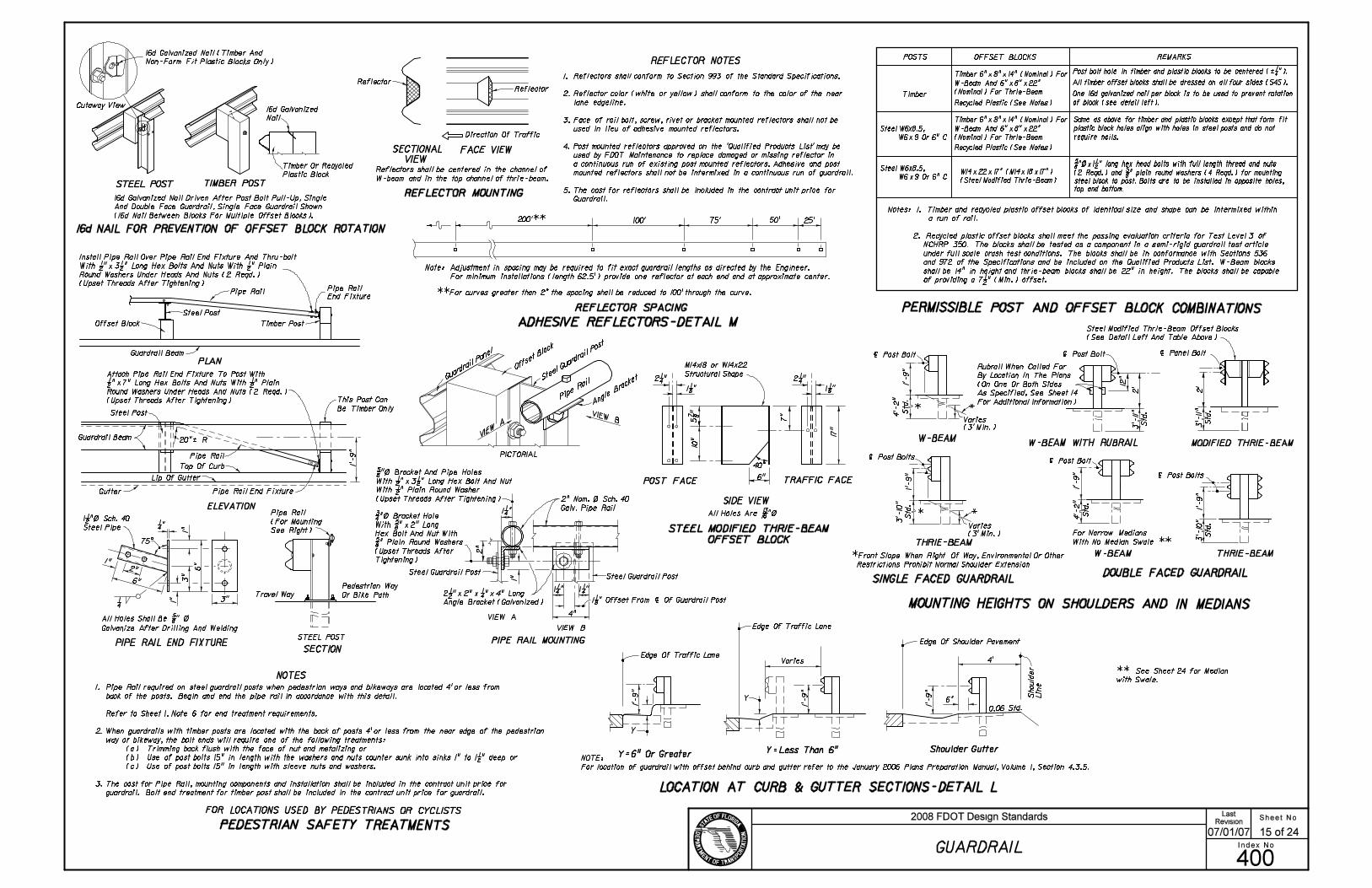
PERMISSIBLE POST AND OFFSET BLOCK COMBINATIONS
MOUNTING HEIGHTS ON SHOULDERS AND IN MEDIANS
SINGLE FACED GUARDRAIL
THRIE-BEAM
LOCATION AT CURB & GUTTER SECTIONS-DETAIL L
FACE VIEW
REFLECTOR MOUNTING
Y
0.06 Std.
Should
er
Lin
e
Edge Of Shoulder Pavement
Shoulder Gutter
Y
THRIE-BEAM
| Post Bolt
Varies
Varies
Varies
Note: Adjustment in spacing may be required to fit exact guardrail lengths as directed by the Engineer.
REFLECTOR SPACING
ADHESIVE REFLECTORS-DETAIL M
25’200’** 100’ 75’ 50’
Y=6" Or Greater
REFLECTOR NOTES
4’-2
"
Std
.
| Post Bolts
(3’ Min.)
ReflectorReflector
Direction Of Traffic
(3’ Min.)
5 7/
8 "
10"
40^
DOUBLE FACED GUARDRAIL
POST FACE
SIDE VIEW
TRAFFIC FACE
STEEL POST TIMBER POST
16d Galvanized
Nail
| Post Bolts
| Post Bolt
| Panel Bolt
Gutter
Top Of Curb
1"
1"
1"
75^
1/4
20"‘ R
Steel Post
Steel Post
Guardrail Beam
PLAN
ELEVATION
Pipe Rail
End Fixture
PIPE RAIL END FIXTURE
3"
1/4 "
3"
2"
Guardrail Beam
Galvanize After Drilling And Welding
Travel Way
SECTION
Pedestrian Way
Or Bike Path
Pipe Rail
Pipe Rail
W-BEAM
W-BEAM
*
*
FOR LOCATIONS USED BY PEDESTRIANS OR CYCLISTS
Timber Post
Pipe Rail End Fixture
STEEL POST
1"Pipe Rail
(For Mounting
See Right)
PIPE RAIL MOUNTING
VIEW A
VIEW B
1. Reflectors shall conform to Section 993 of the Standard Specifications.
2. Reflector color (white or yellow) shall conform to the color of the near
lane edgeline.
3. Face of rail bolt, screw, rivet or bracket mounted reflectors shall not be
used in lieu of adhesive mounted reflectors.
4. Post mounted reflectors approved on the ’Qualified Products List’ may be
used by FDOT Maintenance to replace damaged or missing reflector in
a continuous run of existing post mounted reflectors. Adhesive and post
mounted reflectors shall not be intermixed in a continuous run of guardrail.
5. The cost for reflectors shall be included in the contract unit price for
Guardrail.
Steel Guardrail PostSteel Guardrail Post
This Post Can
Be Timber Only
Lip Of Gutter
16d NAIL FOR PREVENTION OF OFFSET BLOCK ROTATION
SECTIONAL
VIEWTimber Or Recycled
Plastic Block
MODIFIED THRIE-BEAM
*Front Slope When Right Of Way, Environmental Or Other
Restrictions Prohibit Normal Shoulder Extension
PICTORIAL
Offset Block
STEEL MODIFIED THRIE-BEAM
OFFSET BLOCK
16d Galvanized Nail Driven After Post Bolt Pull-Up, Single
And Double Face Guardrail, Single Face Guardrail Shown
(16d Nail Between Blocks For Multiple Offset Blocks).
16d Galvanized Nail (Timber And
Non-Form Fit Plastic Blocks Only)
Cutaway View
Install Pipe Rail Over Pipe Rail End Fixture And Thru-bolt
With 1/2 "!3 1/2 " Long Hex Bolts And Nuts With 1/2 " Plain
Round Washers Under Heads And Nuts (2 Reqd.)
(Upset Threads After Tightening)
Attach Pipe Rail End Fixture To Post With
1/2 "!7" Long Hex Bolts And Nuts With 1/2 " Plain
Round Washers Under Heads And Nuts (2 Reqd.)
(Upset Threads After Tightening)
1’-
9"
1 1/2 "\ Sch. 40
Steel Pipe
6"
6"
All Holes Shall Be 5/8 " \
1’-
9"
1’-
9"
1’-
9"
6"
4’
4"
1 1/4 " 1 1/4 "2 1/2 "!2"! 1/4 "!4" Long
Angle Bracket (Galvanized)
2" Nom. \ Sch. 40
Galv. Pipe Rail
3/4 "\ Bracket Hole
With 5/8 "!2" Long
Hex Bolt And Nut With
5/8 " Plain Round Washers
(Upset Threads After
Tightening)
5/8 "\ Bracket And Pipe Holes
With 1/2 "!3 1/2 " Long Hex Bolt And Nut
With 1/2 " Plain Round Washer
(Upset Threads After Tightening)
1 1/4 "
1 1/8 "
2 1/4 "
6"
7"
All Holes Are 13/16 "\
1’-
9"
3’-
10
"
Std
.1
’-9
"
1’-
9"
4’-2
"
Std
.
2’
1’-
9"
3’-
10
"
Std
.
**For curves greater than 2^ the spacing shall be reduced to 100’ through the curve.
Y=Less Than 6"
Reflectors shall be centered in the channel of
W-beam and in the top channel of thrie-beam.
2"
1 1/8 " Offset From | Of Guardrail Post
17
"
1 1/8 "
2 1/4 "
NOTES
PEDESTRIAN SAFETY TREATMENTS
For minimum installations (length 62.5’) provide one reflector at each end and at approximate center.
Timber
REMARKS
All timber offset blocks shall be dressed on all four sides (S4S).
One 16d galvanized nail per block is to be used to prevent rotation
of block (see detail left).
POSTS OFFSET BLOCKS
5/8 "\!1 1/2 " long hex head bolts with full length thread and nuts
(2 Reqd.) and 5/8 " plain round washers (4 Reqd.) for mounting
steel block to post. Bolts are to be installed in opposite holes,
top and bottom.
Post bolt hole in timber and plastic blocks to be centered (‘ 1/4 ").
Recycled Plastic (See Notes)
Timber 6"!8"!14" (Nominal) For
W-Beam And 6"!8"!22"
(Nominal) For Thrie-Beam
Timber 6"!8"!14" (Nominal) For
W-Beam And 6"!8"!22"
(Nominal) For Thrie-Beam
Recycled Plastic (See Notes)
Same as above for timber and plastic blocks except that form fit
plastic block holes align with holes in steel posts and do not
require nails.
W14!22!17" (M14!18!17")
(Steel Modified Thrie-Beam)
Steel Modified Thrie-Beam Offset Blocks
(See Detail Left And Table Above)
Notes: 1. Timber and recycled plastic offset blocks of identical size and shape can be intermixed within
a run of rail.
2. Recycled plastic offset blocks shall meet the passing evaluation criteria for Test Level 3 of
NCHRP 350. The blocks shall be tested as a component in a semi-rigid guardrail test article
under full scale crash test conditions. The blocks shall be in conformance with Sections 536
and 972 of the Specifications and be included on the Qualified Products List. W-Beam blocks
shall be 14" in height and thrie-beam blocks shall be 22" in height. The blocks shall be capable
of providing a 7 1/2 " (Min.) offset.
Steel W6x8.5,
W6!9 Or 6" C
Steel W6x8.5,
W6!9 Or 6" C
Edge Of Traffic Lane
Edge Of Traffic Lane
M14x18 or W14x22
Structural Shape
Sheet No.
Index No.
2008 FDOT Design StandardsRevision
400
07/01/07
GUARDRAIL
15 of 24
Last
1. Pipe Rail required on steel guardrail posts when pedestrian ways and bikeways are located 4’ or less from
back of the posts. Begin and end the pipe rail in accordance with this detail.
Refer to Sheet 1, Note 6 for end treatment requirements.
2. When guardrails with timber posts are located with the back of posts 4’ or less from the near edge of the pedestrian
way or bikeway, the bolt ends will require one of the following treatments:
(a) Trimming back flush with the face of nut and metalizing or
(b) Use of post bolts 15" in length with the washers and nuts counter sunk into sinks 1" to 1 1/2 " deep or
(c) Use of post bolts 15" in length with sleeve nuts and washers.
3. The cost for Pipe Rail, mounting components and installation shall be included in the contract unit price for
guardrail. Bolt end treatment for timber post shall be included in the contract unit price for guardrail.
3’-
11
"
Std
.
| Post Bolt
12
"
Rubrail When Called For
By Location In The Plans
(On One Or Both Sides
As Specified, See Sheet 14
For Additional Information)
W-BEAM WITH RUBRAIL
2’
3’-
11
"
Std
.
NOTE:
For location of guardrail with offset behind curb and gutter refer to the January 2006 Plans Preparation Manual, Volume 1, Section 4.3.5.
For Narrow Medians
With No Median Swale **
** See Sheet 24 for Median
with Swale.

10’ 10’
Sidewalk Without Utility Strip
See Detail L
A
A
B
C
B
C
SECTION AA
SECTION BB
SECTION CC
Curb And Gutter Type F
PLAN
DETAIL Q
Transition
Sidewalk (Varies)
Sidewalk (Varies)
Sidewalk (Varies)
0.02 (Std.)
0.02 (Std.)
0.02 (Std.)
13’
20’
R
45’
Sidewalk (Width Varies - 5’ Std.; 4’ Min.)
APPROACH TREATMENT FOR CURB AND GUTTER
This Standard Post Must
Be Timber When Steel Post
Used In Guardrail AheadCurb Transition
*
Flared End Anchorage Assembly
(MELT Shown)
Curb flare shall follow guardrail flare, see elsewhere
in this Index for additional guardrail flare information.
3’ 6’-8" 3’ 3’
6’
35’-4" Drop Curb
37’-6" Guardrail Flare
6’-6
"
1’-
9"
1’-
9"
4’
1’-
9"
21’-6" (Curb And Gutter Flare)
*Safety pipe rail is required when the back of steel
guardrail posts are 4’ or less from the near edge of
a pedestrian way or bikeway and post bolt treatment
is required when the back of timber posts are 4’ or
less from the near edge of a pedestrian way or
bikeway; see ’PEDESTRIAN SAFETY TREATMENTS’.
0’-9" (MELT)
1’-3 1/2 " (SRT-350 & REGENT)
2’-3 1/2 "(FLEAT-350)
2’-3 1/2 " SRT/HBA-6 POST
1’-1" (MELT)
1’-8 1/2 " (SRT-350 & REGENT)
1’-7" (FLEAT-350)
1’-7" SRT/HBA-6 POST
2" Misc. Asphalt
2" Misc. Asphalt
2" Misc. Asphalt
2" Misc. Asphalt
Sheet No.
Index No.
2008 FDOT Design StandardsRevision
400
07/01/05
GUARDRAIL
16 of 24
Last
Note: For Proprietary End Treatments See the Qualified Products List.

SPECIAL END SHOE ROUNDED END SECTION
BUFFER END SECTION
W-BEAM
3" Neutral Axis
2" 3"
Direction Of Traffic
Lap
LAPPLICATION
Rail Splice Bolt
Post Bolt -
Metalizing Permitted
Sheet Thickness
10"
Approach Beam,
End Section Or
End Shoe
L
Contour To Fit
Over Beam
Contour To Fit
Over Beam
3" Min.
FLARED END SECTION
^ ‘ For End251
2
30^
30^
3"
55^
55^
55^
(RECTANGULAR PLATE WASHER)
BEAM WASHER
HEX BOLTS AND NUTS
12 1
/4 "
15/16 " R
12"
4 1/4 "
12 1
/4 "
4 1/4 "
8 1/2 " 7 1/2 "2"
5/8 "
5/16 "
15/16
"
25"*
18"
10"
|
| Of Beam
Tolerance (-0,+ 1/16 ")
3/8 " R
25^
10^ (‘1^)
Recess (Both Sides)
(Min.) (In.)
12 1
/4 "
With End Anchorage
Varies
Varies
Field Bend With
Type MELT
Trailing Beam,
Terminal Section
Or End Shoe
|
5/8 " OVAL SHOULDER BUTTON HEAD BOLT
Post Bolt - Single Faced Guardrail Timber Posts
W-Beam Thrie-Beam W-Beam Thrie-Beam
6’-3"
SINGLE BEAM NESTED BEAMS
N/A N/A
N/A N/A
Note: The values shown should be utilized unless changes
are supported by imperical validation. Those desiring
to develop offset values from the simulated deflection
values shown in Table 5.4 of the AASHTO Roadside
Design Guide are cautioned to proceed only if back-
ground in the table development is understood.
THREAD
LENGTH
Measured From Face Of Guardrail To
Front Of Above Ground Rigid Hazard
Note: For beam washer requirements on end terminals, see individual
end anchorage assembly details. Washers are to be used where
necessary to accomplish alignment or where the posts bolt head
shows tendency to pull through the rail slot. Washers installed on
guardrail, between end anchorages, prior to July 1, 1990 may remain
in place until the guardrail is relocated or until repairs require
removal and reinstallment of a post bolt.
W-BEAM RAIL SPLICE
Note: For application information see individual
end anchorage assembly details.
W-BEAM BACK-UP PLATE
3 1/4 "
3 3/16 "
1 1/16 "
2 1/4 "
2 5/
16 "
3 1/
4 "
1 21/32 "
1 1/8
"
15/16 " R
29/32 "!1 1/8 " Slots
3/4 "!2 1/2 " Slot
3’-1 1/2 "
1’-6 3/4 "
4’
3’
3’-3"
2’-8" 2’-8"
2’-4"
2’-4"
2’
OFFSETS (Ft.)
POST
SPACING
(Ft.)
MINIMUM OFFSET FOR
SINGLE FACED GUARDRAIL (Ft.)
(In.)
1 1/4 " Full Length
4"
4"
4"
Special bolts having lengths of 10" or greater shall have a
thread length of not less than 4".
* Use of the 25" AASHTO-AGC-ARTBA standard length post bolt
on double faced guardrail that results in the bolt projecting more
than 3/4 " beyond the face of the nut after pull-up shall be trimmed
to 3/4 " reveal and metalized with organic zinc-rich coating.
5/8 " STEEL WASHER
11/16 "
1 3/4 "
Metal Thickness
9
64" Base
7/32 "
1 3/8 " R
1 3/3
2 "
1 3/8 "
3/4 "!2 1/2 " Slot
6"
11/16 "
1"\! 1/16 " Deep
1 1/4 "
5/8 " MODIFIED HEAVY
HEX NUT (RECESSED NUT)
1 1/2 "
1 3/4
"
11/16 "!1" Slot 7/8 "
3/16 " Base Metal
Thickness
4 1/4 "
Note: 5/8 "\ Steel washer required with splice bolts
29/32 "!1 1/8 " Slots
(Typ.) (8 Reqd.)
15/16 "\ Hole (Typ.)
(4 Reqd.)
3 1/
2 "
3 1/
2 "
3/4 "\ Hole For Use4"4" 4 1/4 "
3/4 "!2 1/2 " Slot
3/4 "!2 1/2 " Slot
2’-6"
3 3/
8 "
2’-3 1/2 "
3 3/
8 "
12 1
/4 "
2"4 1/4 " 4 1/4 "
29/32 "!1 1/8 " Slots
(Typ.) (8 Reqd.)
1’-
4 1
/8 "
Ap
pro
x.
29/32 "!1 1/8 " Slots
(Typ.) (4 Reqd.)
12 1
/4 "
6 1/4 " R
29/32 "!1 1/8 " Slots
(Typ.) (4 Reqd.)
12 1
/4 "
2" 8 1/2 " 7 1/2 "
1’-9
" o
r 2
’-6
"
1’-3" R Standard
(10 1/2 " R When Used
For End Anchorage
Type MELT)
1’-4
1/8
"
1’-4
1/8
"
3/4 "!2 1/2 " Slots
With Post Bolt And Nut
With 5/8 " Steel Washer
Under Nut
Anchorage Type
MELT and CRT.
HS Hex bolts for THRIE-BEAM TERMINAL CONNECTORS shall conform to the
requirements of ASTM A449 (Type 1) with heavy hex nuts and washers. All other
hex bolts shall conform to the requirements of ASTM A563. Bolts, nuts and washers
shall be hot dip galvanized. Heavy hex nut may be used in lieu of hex nuts and hex
nuts used for jam nuts.
For applications where special bolts having lengths greater
than 25" are required, the Contractor may use a 5/8 "\ threaded
rod (field cut to length). A hex nut and beam washer shall
be used at the guardrail face with no more than 3/4 " of the
threaded rod projecting beyond the top of the nut. The
projecting thread on both ends shall be distorted to secure
the nuts, and both ends of the threaded rod metalized with
organic zinc-rich coating.
Post Bolt - Double Faced Guardrail Timber Posts
Double Faced Guardrail Steel Posts
Single Or Double Faced Guardrail
Timber Or Recycled Plastic Offset
Block(s) On Steel Post
As An Option, A Single 25"*
Long Post Bolt May Be Used
Sheet No.
Index No.
2008 FDOT Design StandardsRevision
400
07/01/07
GUARDRAIL
17 of 24
Last
Note: The round washer is not intended for use under the recess nut for
the beam to beam rail splice. The washer is required under the recess
nut for connecting the beam to the special end shoe; under the post
bolt nut for connecting the beam to the timber post and offset blocks;
for connecting the beam to steel posts with timber offset blocks; under
the hex bolt head for securing the beam anchor plate to the beam; and,
for general guardrail connections by 5/8 "\ hex bolts and nuts and under
hex nut for connecting rubrail to wood and steel posts. For supplemental
information see BEAM ANCHOR PLATE, PERMISSIBLE POST AND
OFFSET BLOCK COMBINATIONS, individual end anchorage assembly
details, SPECIAL STEEL GUARDRAIL POSTS, SPECIAL END SHOE,
W-BEAM RAIL SPLICE, THRIE-BEAM RAIL SPLICE, and THRIE-BEAM
TERMINAL CONNECTOR details.

3" Neutral Axis
2" 3"
THRIE-BEAM
Neutral Axis
Symmetrical
55^
55^
55^
25^
About |
3/8 " R
15/16 " R
15/16 " R
29/32 "!1 1/8 " Slots
3/4
"!2
1/2
" S
lots
Tolerance (-0,+ 1/16 ")
10^ (‘1^)
Sheet
Thickness
THRIE-BEAM TERMINAL CONNECTOR
4 1/4 " 2"
20
"
12 1
/4 "
6’-3"
2" Min.
W-THRIE BEAM TRANSITION SECTION
16"
2"
BACK VIEWSECTIONS
Hex (Jam) Nut
Hex Nut
BEAM ANCHOR PLATE
W-Beam
Anchor Plate
15/16 " R
3/8 " R
1/4
Three
Sides
35^
Swage Fitting
CABLE ASSEMBLY
Swage Connected To Studs
5 1/4 "
3/8 "
24"
12
"
L
BEARING PLATE
BREAKAWAY TERMINAL
POST SLEEVE
18"
L
24"
SOIL PLATES
(Typ.) (8 Reqd.)
Direction Of Traffic
Lap
4 1/4 "
THRIE-BEAM RAIL SPLICE
Trailing Beam, W-Thrie
Beam Transition Section
Or Terminal Connector
Approach Beam, W-Thrie
Beam Transition Section
Or Terminal Connector
4 1/4 "
3/4 "!2 1/2 " Post Bolt Slots (Typ.)
29/32 "!1 1/8 " Splice Bolt Slots (Typ.)
3’-1 1/2 "3’-1 1/2 "
2" Min.4 1/4 "4 1/4 "2"
3/4 "!2 1/2 " Post Bolt
Slots (2 Reqd.)
29/32 "!1 3/4 " Slots
Rotated 50^ (Typ.)
(12 Reqd.)
4 1/4 "4 1/4 "
3 3/
8 "
2’-6"
4" 4"
Note: 5/8 "\ steel washer required with splice bolts
15/16 "\ Holes (Typ.)
(7 Reqd.)
3/4 "\ Holes
(2 Reqd.)
20" (
‘ 1/4
")
3 13/1
6 "3 1
3/16 "
3 13/1
6 "3 1
3/16 "
3/4 "!2 1/2 " Slots (2 Per Beam)
With Post Bolts And Nuts
With 5/8 " Steel Washers
Under Nuts (2 Reqd.)
4 1/4 "
3 1/4 "
3 3/16 "
2 1/4 "
1 1/16 "
1 21/32 "
2 3/
8 "
3 1/
4 "
1 1/8
"3
1/4
"
20" (
‘ 1/4
")
1/4 " Steel P, Galvanized
9"
3/4 "\ Holes
6"9" 9"
9" 9"6"
24"
3/4 "\ Holes
5/8 " Steel P
5"
8"
1 1/8 "\ Hole
4"
8"
6"
3/4 "\ Holes
3/4 "\ Holes
1 15/1
6 "
1 5/8 "
1 3/4
"
2 3/8 "
3 3/8 "
3/4 "\ Holes
4"4"4"2"
1"\ Anchor Rod And
Cable Assembly
Shaped Steel Plate
(16"!12 9/16 "! 3/16 ")
1"\!7" Stud, Full Threads,
Galvanized (Both Ends)
6’-6"
7"
1 5/8
"
1 1/4
"
3/4 "\ Galvanized Cable (6!19)
3/8 "
2 11/16 "
5 1/2
64
9Washer (2" OD, 1 1/16 "ID, Thick)
3/8 "!2 3/4 "!3" Steel End Plate
With 1 1/8 " Center Hole
2" Nom. Dia.
(2.067" ID, 2.375" OD)
Note: Cable assemblies shall be in accordance with the specifications of
AASHTO-AGC-ARTBA ’A Guide To Standardized Highway Barrier Hardware’
Cable Anchor Assembly FCA01. An additional cable assembly 9’ in length with a
swaged fitting on one (1) end is required for each end anchorage assembly Type CRT.
5/8 "-11!1 1/2 " Long Hex Head
Bolts And Nuts With Plain
Round Washers Under Heads
(8 Reqd.)
2"4"
8"
8"
3 13/16 "
1 1/2 "
SPECIAL END SHOETHRIE-BEAM TERMINAL CONNECTOR FILLER PLATE
2 7/
8 "
7 5/
8 "
7 5/
8 "
12"
21"
3 13/1
6 "
3 13/1
6 "
2"4" 4"
5/8 " Plate For Bridge Traffic Railing Barrier
1/4 " Plate For Barrier Walls 1/4 " Plate For All Applications
12"
12"
2 3/
8 "
2 3/
8 "
2"4" 4"
3 1/
2 "
3 1/
2 "
3/4 "\
Hole
All Holes 1"\ Except As Shown
GALVANIZED STEEL BACK-UP PLATES FOR CONNECTING SPECIAL END SHOES AND TERMINAL
CONNECTORS TO CONCRETE BRIDGE TRAFFIC RAILING BARRIERS AND CONCRETE BARRIER WALLS
1 1/4 " Plate
See Detail J For Application
| Post Bolt Slot
Sheet No.
Index No.
2008 FDOT Design StandardsRevision
400
07/01/05
GUARDRAIL
18 of 24
Last
12"
3/4 "!2 1/2 " Slot
6"
20" (
‘ 1/4
")
Back-up plate required behind rail elements at
intermediate (non-splice) posts when steel
offset block used.
THRIE-BEAM BACK-UP PLATE
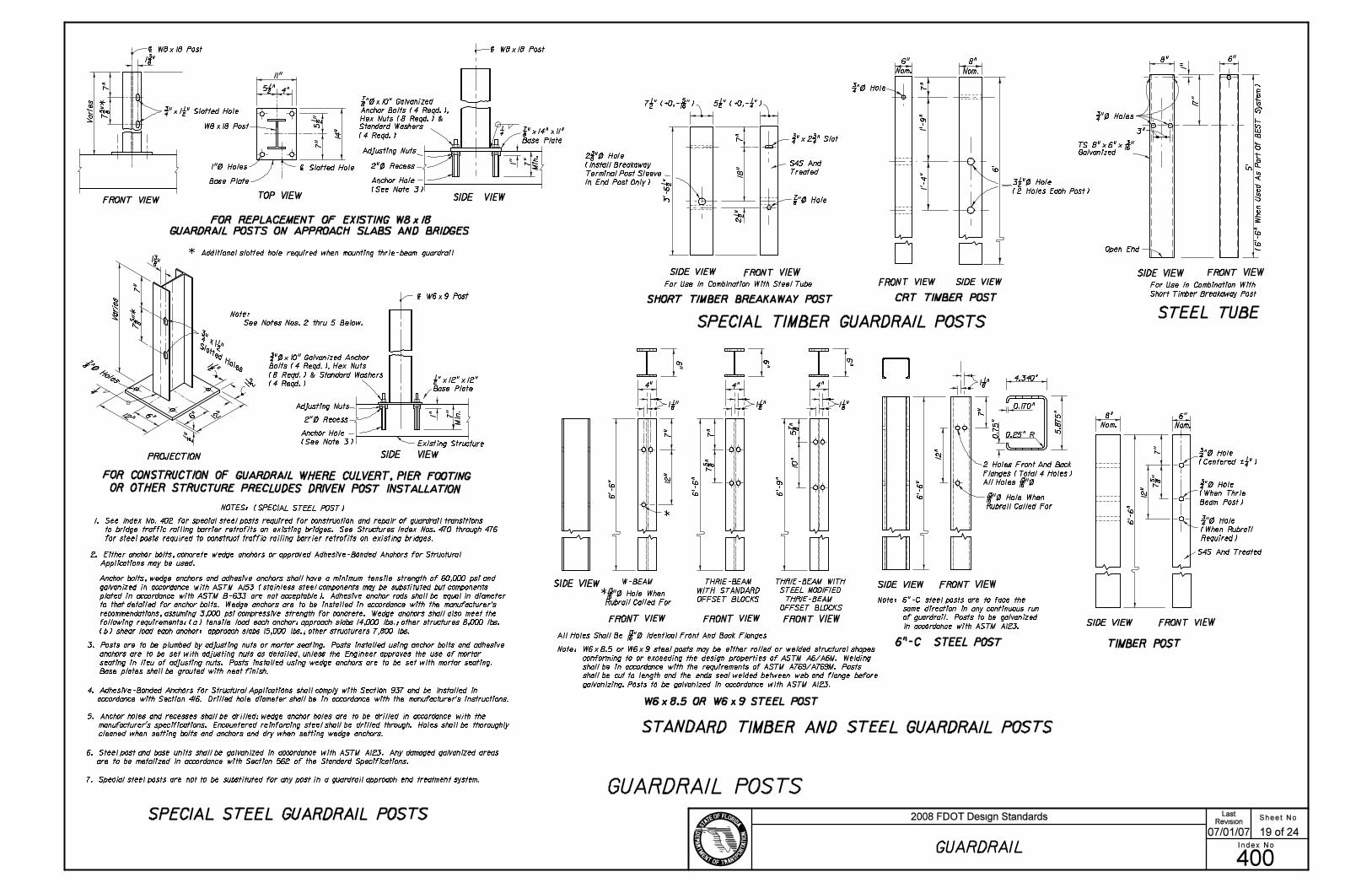
18"
S4S And
Treated
3"
1"
17
"
Open End
Galvanized
11"
Base Plate
14"
Adjusting Nuts
1"
Min
.
2 Holes Front And Back
SIDE VIEW FRONT VIEW
SIDE VIEW
FRONT VIEW
SIDE VIEW FRONT VIEW
Vari
es
FRONT VIEW SIDE VIEWTOP VIEW
Flanges (Total 4 Holes)
NOTES: (SPECIAL STEEL POST)
Existing Structure
Adjusting Nuts
SIDE VIEWPROJECTION
| Slotted Hole
Note:
See Notes Nos. 2 thru 5 Below.
Min
.
5 1/2 "
5 1/
2 "
1"
12
"
7 5/
8 "
12
"
plated in accordance with ASTM B-633 are not acceptable). Adhesive anchor rods shall be equal in diameter
3. Posts are to be plumbed by adjusting nuts or mortar seating. Posts installed using anchor bolts and adhesive
anchors are to be set with adjusting nuts as detailed, unless the Engineer approves the use of mortar
seating in lieu of adjusting nuts. Posts installed using wedge anchors are to be set with mortar seating.
Base plates shall be grouted with neat finish.
5. Anchor holes and recesses shall be drilled; wedge anchor holes are to be drilled in accordance with the
manufacturer’s specifications. Encountered reinforcing steel shall be drilled through. Holes shall be thoroughly
cleaned when setting bolts and anchors and dry when setting wedge anchors.
SHORT TIMBER BREAKAWAY POST
Anchor Bolts (4 Reqd.),
Hex Nuts (8 Reqd.) &
7/8 "!14"!11"
Base Plate
CRT TIMBER POST
Nom. Nom.
FOR CONSTRUCTION OF GUARDRAIL WHERE CULVERT, PIER FOOTING
OR OTHER STRUCTURE PRECLUDES DRIVEN POST INSTALLATION
SPECIAL STEEL GUARDRAIL POSTS
GUARDRAIL POSTS
SIDE VIEWFRONT VIEW
SIDE VIEW FRONT VIEWFRONT VIEWSIDE VIEW
TIMBER POST
STANDARD TIMBER AND STEEL GUARDRAIL POSTS
SPECIAL TIMBER GUARDRAIL POSTSSTEEL TUBE
For Use In Combination With
Short Timber Breakaway Post
For Use In Combination With Steel Tube
S4S And Treated
12
"
*
FRONT VIEW
W-BEAM
FRONT VIEW
7 5/
8 "
10"
5 7/
8 "
1/2 "!12"!12"
Base Plate
THRIE-BEAM WITH
STEEL MODIFIED
THRIE-BEAM
OFFSET BLOCKS
Nom. Nom.
7 1/2 " (+0,- 5/16 ") 5 1/2 " (+0,- 1/4 ")
THRIE-BEAM
WITH STANDARD
OFFSET BLOCKS
7 5/
8 "*
Note: 6"-C steel posts are to face the
same direction in any continuous run
of guardrail. Posts to be galvanized
in accordance with ASTM A123.
2. Either anchor bolts, concrete wedge anchors or approved Adhesive-Bonded Anchors for Structural
Applications may be used.
6"8"
7"
6’-6"
3/4 "\ Hole
(Centered ‘ 1/4 ")
3/4 "\ Hole
(When Thrie
Beam Post)
3/4 "\ Hole
(When Rubrail
Required)
4.340"
5.8
75"
0.170"
0.25" R0.7
5"
7"
1 1/8 "
6’-6" All Holes 13/16 "\
13/16 "\ Hole When
Rubrail Called For
6"-C STEEL POSTAll Holes Shall Be 13/16 "\ Identical Front And Back Flanges
* 13/16 "\ Hole When
Rubrail Called For
6"
4"
1 1/8 "
6"6"
4"4"
1 1/8 "1 1/8 "
6’-9"
6’-6"
7"
7"
6’-6"
6"8"
3/4 "\ Holes
TS 8"!6"! 3/16 "
5’
(6’-6" W
hen U
sed A
s P
art
Of B
ES
T S
yste
m)
3 1/2 "\ Hole
(2 Holes Each Post)
6" 8"
7"
1’-
9"
1’-
4"
6’
3/4 "\ Hole
7"
2 1/
2 "
3’-
6 1
/2 "
3/4 "!2 3/4 " Slot
7/8 "\ Hole
2 3/8 "\ Hole
(Install Breakaway
Terminal Post Sleeve
In End Post Only)
| W8!18 Post
7"
7/8 "\!10" Galvanized
Standard Washers
(4 Reqd.)
2"\ Recess
4"
7"
1"\ Holes
W8!18 Post
| W8!18 Post
1 3/8 "
7"
3/4 "!1 1/2 " Slotted Hole
| W6!9 Post
3/4 "\!10" Galvanized Anchor
Bolts (4 Reqd.), Hex Nuts
(8 Reqd.) & Standard Washers
(4 Reqd.)
2"\ Recess
7"
Anchor bolts, wedge anchors and adhesive anchors shall have a minimum tensile strength of 60,000 psi and
recommendations, assuming 3,000 psi compressive strength for concrete. Wedge anchors shall also meet the
following requirements: (a) tensile load each anchor: approach slabs 14,000 lbs.; other structures 8,000 lbs.
(b) shear load each anchor: approach slabs 15,000 lbs.; other structurers 7,800 lbs.
Anchor Hole
(See Note 3)
Anchor Hole
(See Note 3)
W6!8.5 OR W6!9 STEEL POST
Note: W6!8.5 or W6!9 steel posts may be either rolled or welded structural shapes
conforming to or exceeding the design properties of ASTM A6/A6M. Welding
shall be in accordance with the requirements of ASTM A769/A769M. Posts
shall be cut to length and the ends seal welded between web and flange before
galvanizing. Posts to be galvanized in accordance with ASTM A123.
galvanized in accordance with ASTM A153 (stainless steel components may be substituted but components
to that detailed for anchor bolts. Wedge anchors are to be installed in accordance with the manufacturer’s
4. Adhesive-Bonded Anchors for Structural Applications shall comply with Section 937 and be installed in
accordance with Section 416. Drilled hole diameter shall be in accordance with the manufacturer’s instructions.
* Additional slotted hole required when mounting thrie-beam guardrail
FOR REPLACEMENT OF EXISTING W8!18
GUARDRAIL POSTS ON APPROACH SLABS AND BRIDGES
1. See Index No. 402 for special steel posts required for construction and repair of guardrail transitions
to bridge traffic railing barrier retrofits on existing bridges. See Structures Index Nos. 470 through 476
for steel posts required to construct traffic railing barrier retrofits on existing bridges.
Sheet No.
Index No.
2008 FDOT Design StandardsRevision
400
07/01/07
GUARDRAIL
19 of 24
Last
6. Steel post and base units shall be galvanized in accordance with ASTM A123. Any damaged galvanized areas
are to be metalized in accordance with Section 562 of the Standard Specifications.
7. Special steel posts are not to be substituted for any post in a guardrail approach end treatment system.
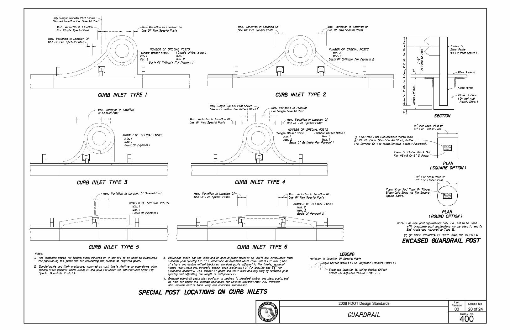
CURB INLET TYPE 1 CURB INLET TYPE 2
CURB INLET TYPE 3 CURB INLET TYPE 4
CURB INLET TYPE 5 CURB INLET TYPE 6
SECTION
PLAN
PLAN
ENCASED GUARDRAIL POST
SPECIAL POST LOCATIONS ON CURB INLETS
Min. 1
Max. 1
Basis Of Payment 1
Min. 1
Max. 1
Basis Of Payment 1
One Of Two Special Posts
Max. Variation In Location On
One Of Two Special Posts
Min. 1
Max. 2
Min. 1
Max. 2
Basis Of Estimate For Payment 1
Variation In Location Of Special Post:
Expanded Location By Using Double Offset
Min. 2
Max. 2
Basis Of Estimate For Payment 2
Min. 1
Max. 2
Min. 1
Max. 1
Basis Of Estimate For Payment 1
One Of Two Special Posts
Min. 2
Max. 2
Basis Of Payment 2
Misc. Asphalt
2" A
t F
ace O
f R
ail
To Facilitate Post Replacement Install With
Option Above.
Only Single Special Post Shown
1. The locations shown for special posts mounted on inlets are to be used as guidelines
for positioning the posts and for estimating the number of required posts.
2. Special posts and their anchorages mounted on curb inlets shall be in accordance with
3. Variations shown for the locations of special posts mounted on inlets are established from
LEGEND
One Of Two Special Posts One Of Two Special Posts
Only Single Special Post Shown
For Single Special Post
One Of Two Special Posts
One Of Two Special Posts
Timber Or
Steel Posts
Notes:
15" For Steel Post Or
17" For Timber Post
NUMBER OF SPECIAL POSTS
NUMBER OF SPECIAL POSTS
NUMBER OF SPECIAL POSTS
NUMBER OF SPECIAL POSTS
NUMBER OF SPECIAL POSTS
NUMBER OF SPECIAL POSTS
Max. Variation In Location
Of Special Post
Max. Variation In Location Of Special Post Max. Variation In Location Of
Max. Variation In Location Of
Max. Variation In Location
Max. Variation In Location OfMax. Variation In Location Of
Max. Variation In Location Of
Max. Variation In Location Of
Max. Variation In Location Of
One Of Two Special Posts
Max. Variation In Location
For Single Special Post
Foam Wrap
(Normal Location For Special Post)
Reinf. Steel)
(Single Offset Block) (Double Offset Block)
(Do Not Add
(Single Offset Block) (Double Offset Block)
(Normal Location For Offset Block)
(SQUARE OPTION)
(ROUND OPTION)
Single Offset Block (s) On Adjacent Standard Post (s)
Blocks On Adjacent Standard Post (s)
Block-Outs Same As For Square
Class ~ Conc.
4. Encased guardrail posts shall conform in section to standard timber and steel posts, and
shall include cost of foam wrap and concrete encasement.
TO BE USED PRINCIPALLY OVER SHALLOW UTILITIES
3"
15" For Steel Post Or
17" For Timber Post
spacing and adjusting the length of rail panel (s).
expansion anchors). The number of posts and their locations may vary by reducing post
Foam Or Timber Block-Out
Foam Wrap And Foam Or Timber
special steel guardrail posts Sheet 19, and paid for under the contract unit price for
Special Guardrail Post, EA.
be paid for under the contract unit price for Special Guardrail Post, EA. Payment
standard post spacing (6’-3"); clearance of standard posts from inlets (4" min.); use
of single and double offset blocks on standard posts adjacent to the inlets; optional
flange mountings; and, concrete anchor edge distances (2" for grouted and 3 3/4 " for
For W6!9 Or 6" C Posts
3/16 " Plastic Foam Sheet On All Sides, Below
Varie
s (
2’ M
in.)
Vari
es (
4’-
3" M
in.
Fo
r W
-Beam
, 4
’-7
" M
in.
Fo
r T
hri
e-B
eam
)
1’-
9"
(W6!9 Post Shown)
The Surface Of The Miscellaneous Asphalt Pavement.
Note: For line post applications only, i.e., not to be used
with breakaway post applications nor be used to modify
End Anchorage Assemblies Type ~~.
Sheet No.
Index No.
2008 FDOT Design StandardsRevision
400
00
GUARDRAIL
20 of 24
Last

End Measurement For Guardrail Payment
12" 16"
Cable To Be Drawn Taut
With Hand Wrench Prior
To Setting Jam Nuts
Steel Tube
Bearing Plate
compacting to provide full
passive soil resistance to
all surfaces of the tube and
soil plate.
plate as a unit with a dummy
timber post to prevent damage
to breakaway post.
Two 8d Nails ToPrevent Rotation
Anchor Plate Cable Assembly
FRONT VIEW
Note: Steel tubes and attached soil
plate may be installed by:
(1) Excavating, backfilling and
(2) Driving steel tube and soil
6’-3"
Post Sleeve
Soil Plate
12" 16"
Standard PostAnchor Plate
No Cover Required
Trailing Rail
Anchor Rod
30"
Concrete Anchor Block
30"
Steel End Plate, Washer, Hex
See Note Below
On Trailing End Section
Flared Or Rounded End Section
For Approach End Anchorage
Buffer End Section
Suit Anchorage Alignment.
Only One Anchorage Required.
Anchorage To Be On Approach
Rail When Both Approach
And Trailing Guardrails Are
See Note Below
Anchor Rod
30"
FRONT VIEW
TOP VIEW
Position Varies
End Measurement For Guardrail Payment
Approach Rail (Position Varies)
Nut And Hex (Jam) Nut
(Block To Be Positioned To
Connected.)6’-3"
1 1/2 " ID Pipe Sleeve
Beveled Washer And Hex Nut
3’-6
" S
td.
6’-3" To Next Post
Anchor PlateCable Assembly
Soil Plate
TOP VIEW - DOUBLE FACE
TOP VIEW - SINGLE FACE
Short Timber
Breakaway Post
CONCRETE ANCHOR BLOCK OPTION
Buffer End Section
END ANCHORAGE ASSEMBLY TYPE ~~
CABLE ANCHOR OPTION
Anchor Plate
Soil Plate
18"!24"! 1/4 "
TYPE ~~ NOTES
Flared End Section
(Rounded End Section When Guardrail
Located Adjacent To Pedestrian Way
Or Bikeway)
Turnbuckle to be used only for guardrail that is reset vertically. The existing anchor rod (1" or 1 1/4 " Dia.) shall be field cut,
End Section
Short Timber Breakaway Post
Short Timber Breakaway Post
Misc. Asphalt Pavt.
10’ Approach End Guardrail
Misc. Asphalt Pavt.
6’ Trailing End Guardrail
Misc. Asphalt Pavt. 10’ Approach End Guardrail
threaded 4" on each end, and, metalized in accordance with Sections 562 and 971 of the Standard Specifications. The cost
for cutting, threading, metalizing and the turnbuckle shall be included in the contract unit price for Reset Guardrail, LF.
1’-
9"
1"\ Galv.
Turnbuckle (6")
Galvanized 4"!4"! 3/4 " Plate
4’-9"
Turnbuckle (6")
5/8 "!25" Long Post Bolt And Nut With
Beam Washer Under Head And Under Nut
(Timber Post And Block)
5/8 "!18" Long Post Bolt And Nut With Beam Washer
Under Head And 5/8 " Plain Round Washer Under Nut
(Timber Post And Block)
5/8 "!10" Long Post Bolt And Nut
With Beam Washer Under Head And
5/8 " Plain Round Washer Under Nut
Misc. Asphalt Pavt.
6’ Trailing End Guardrail
1’-
9"
5/8 "!18" Long Bolt And
Nuts With 5/8 " Plain Round
Washer Under Head And Nut
(2 Req’d.)
5/8 "!10" Long Bolt And Nut With 5/8 " Plain
Round Washer Under Head And Nut
Timber Or Steel Post With Timber
Block May Be Used, Timber Post And
Block Shown (This Post Must Be
Timber In Steel Post Run Of Rail
Adjacent To Pedestrian Way
Or Bikeway, To Provide Anchorage
For Pipe Rails As Required)Misc. Asphalt Pavt.
Misc. Asphalt Pavt.
Misc. Asphalt Pavt.
Hex Nut & Hex (Jam) Nut
And Washer Each End
Hex Nut & Hex (Jam) Nut
And Washer Each End
The payment for the items of End Anchorage Assembly Type ~~ shall be full compensation for furnishing and installing the
Beam Anchor Plate, Anchor Rod, Pipe Sleeve, Anchor Block, either Flared, Rounded or Buffer End Section, and the necessary
hardware.
The payment for the items of End Anchorage Assembly Type ~~ shall be full
compensation for furnishing and installing either the Round or the Buffer
End Section, the Beam Anchor Plate, Cable Assembly, Pipe Sleeve, SoilPlate,
Steel Tube, Bearing Plate, Short Timber Breakaway Post, Offset Blocks and
the necessary hardware.
Sheet No.
Index No.
2008 FDOT Design StandardsRevision
400
07/01/05
GUARDRAIL
21 of 24
Last
1. Unless specified in the plans, the contractor can supply either the cable anchor option or the
concrete anchor block option.
2. Type ~~ end anchorage assemblies are approved for all speeds and are intended for use as:
(a) trailing end anchorages for single face free standing guardrail systems;
(b) approach end anchorages for single face free standing guardrail systems when end anchorage
is located outside of the clear zone; and,
(c) both approach and trailing ends of double face guardrail systems.
Crash cushions shall be constructed at or in lieu of approach Type ~~ end anchorages located
inside the clear zone.
End anchorage for thrie beam guardrail shall be constructed the same as detailed for W-beam,
except use thrie beam rail and end section; and the Anchor Plate is to be attached to the bottom
corrugation of the thrie beam.
3. These end anchors are to be paid for under the contract unit price for Guardrail, End Anchorage
Assembly (Type ~~), EA as called for in the plans or by permit.
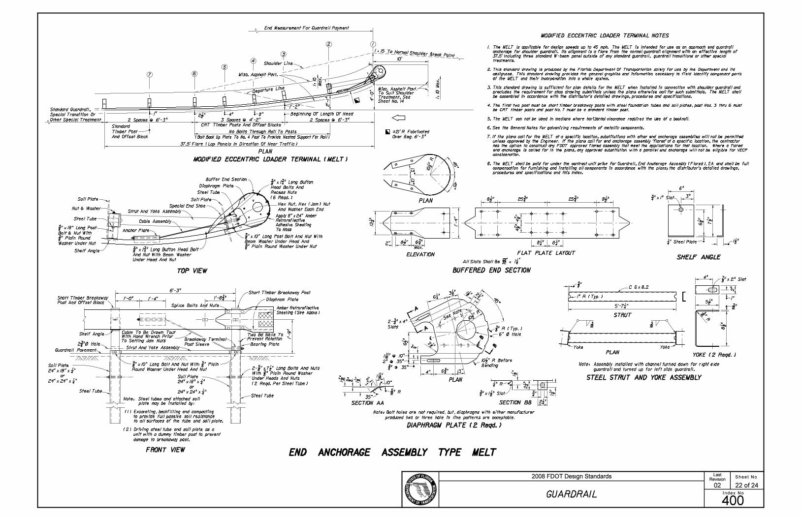
SHELF ANGLE
BUFFERED END SECTION
STEEL STRUT AND YOKE ASSEMBLY
END ANCHORAGE ASSEMBLY TYPE MELT
Note: Assembly installed with channel turned down for right side
guardrail and turned up for left side guardrail.
PLAN
MODIFIED ECCENTRIC LOADER TERMINAL (MELT)
FRONT VIEW
TOP VIEW
1:
10 M
ax.
2 Spaces @ 6’-3"3 Spaces @ 4’-2"2 Spaces @ 6’-3"
No Bolts Through Rail To Posts
Beginning Of Length Of Need
Departure Line
1"
10’
CRT Timber Posts And Offset Blocks
Misc. Asphalt Pavt.
Standard
Timber Post
And Offset Block
MODIFIED ECCENTRIC LOADER TERMINAL NOTES
Misc. Asphalt Pavt.To Suit ShoulderTreatment, SeeSheet No. 14
Standard Guardrail,
Special Transition Or
Other Special Treatment
(Bolt Back Up Plate To No. 4 Post To Provide Nested Support For Rail)
Note: Bolt holes are not required, but, diaphragms with either manufacturer
produced two or three hole in line patterns are acceptable.
DIAPHRAGM PLATE (2 Reqd.)
1:
10
Max.
Shoulder Line
1 : 15 To Normal Shoulder Break Point
12
3
4
5
67
6’-3"
STRUT
Yoke Yoke
2"
C 6!8.2
4"
2"
1"
3"
2" @ 35^
4"
6" \ Hole
1’-
4"
2"
1’-0" 1’-4"
1’-
9"
1" R (Typ.)
End Measurement For Guardrail Payment
Steel Tube
Cable To Be Drawn Taut
With Hand Wrench PriorTo Setting Jam Nuts
Steel Tube
Bearing Plate
to provide full passive soil resistance
Two 8d Nails ToPrevent Rotation
Guardrail Pavement
Note: Steel tubes and attached soil
plate may be installed by:
Strut And Yoke Assembly
Diaphram Plate
Shelf Angle
Short Timber Breakaway Post
Breakaway Terminal
Post Sleeve
PLAN
13^
|
45^
PLAN
45^
45^
13^
13^
PLAN
ELEVATION FLAT PLATE LAYOUT
YOKE (2 Reqd.)
SECTION AA SECTION BB
10^
35^
Max.
See Note
Splice Bolts And Nuts
6"
3/4 "!1" Slot
2- 3/4 "!4"
Slots
32
291
1
8
Short Timber Breakaway
Post And Offset Block
Amber Retroreflective
Sheeting (See Above)
All Slots Shall Be !
(1) Excavating, backfilling and compacting
to all surfaces of the tube and soil plate.
(2) Driving steel tube and soil plate as a
unit with a dummy timber post to prevent
damage to breakaway post.
Buffer End Section
Soil Plate
Special End Shoe
Cable Assembly
Anchor Plate
Strut And Yoke AssemblyNut & Washer
Soil Plate
Steel Tube
Shelf Angle
Steel Tube
5/8 "!18" Long Post
Bolt & Nut With
5/8 " Plain Round
Washer Under Nut
Apply 8"!24" Amber
Retroreflective
Adhesive Sheeting
To Nose
5/8 "!1 3/4 " Long Button
Head Bolts And
Recess Nuts
(6 Reqd.)
5/8 "!10" Long Post Bolt And Nut With
Beam Washer Under Head And
5/8 " Plain Round Washer Under Nut 5/8 "!1 3/4 " Long Button Head Bolt
And Nut With Beam Washer
Under Head And Nut
5/8 "!10" Long Bolt And Nut With 5/8 " Plain
Round Wasner Under Head And Nut
2 3/8 "\ Hole
1’-8 3/4 "
2- 5/8 "!7 1/2 " Long Bolts And Nuts
With 5/8 " Plain Round Washer
Under Heads And Nuts
(2 Reqd. Per Steel Tube)
10 1
/2 "
R
12 1
/4 "
8 1/2 " 6 3/4 "
8 1/2 " 8 1/2 "25 3/4 " 25 3/4 "
8 1/4 " 8 1/4 "
4 7/
8 "
4 7/
8 "
1 7/16
"
5/8 "
1 1/8
"
5/16 " R
1 11/16 "
1 11/16 " @ 10^
3/4 " @ 35^6 3/4 "
3/8 " R (Typ.)
10 1/2 " R Before
Bending
6 1/
2 "
3/4 "
2 1/2 "
10 1/2 " R
6 1/4 "3 1/2 " 1 1/8 " 2 1/4 "
2 1/4 "
3/4 " 1 1/8
"
2 1/
4 "
1 1/8
"
1/4 " R
3/4 "!1 1/8 " Slot
8 1/
8 "
5/8 "
5’-7 1/4 "
7/8 "!2" Slot
5 1/2 "
5/16 " R
3/16 "
1/4 " Steel Plate 1 1/2 "
6 1/
8 "
7 1/
2 "
1. The MELT is applicable for design speeds up to 45 mph. The MELT is intended for use as an approach end guardrail
anchorage for shoulder guardrail. Its alignment is a flare from the normal guardrail alignment with an effective length of
37.5’ including three standard W-beam panel outside of any standard guardrail, guardrail transitions or other special
treatments.
2. This standard drawing is produced by the Florida Department Of Transportation solely for use by the Department and its
assignees. This standard drawing provides the general graphics and information necessary to field identify component parts
of the MELT and their incorporation into a whole system.
3. This standard drawing is sufficient for plan details for the MELT when installed in connection with shoulder guardrail and
precludes the requirement for shop drawing submittals unless the plans otherwise call for such submittals. The MELT shall
be assembled in accordance with the distributor’s detailed drawings, procedures and specifications.
4. The first two post must be short timber breakaway posts with steel foundation tubes and soil plates, post Nos. 3 thru 6 must
be CRT timber posts and post No. 7 must be a standard timber post.
5. The MELT can not be used in medians where horizontal clearance requires the use of a backrail.
6. See the General Notes for galvanizing requirements of metallic components.
7. If the plans call for the MELT at a specific location, substitutions with other end anchorage assemblies will not be permitted
unless approved by the Engineer. If the plans call for end anchorage assembly ’flared’ at a specific location, the contractor
has the option to construct any FDOT approved flared assembly that meet the applications for that location. Where a flared
end anchorage is called for in the plans, any approved substitution with a parallel end anchorage will not be eligible for VECP
consideration.
8. The MELT shall be paid for under the contract unit price for Guardrail, End Anchorage Assembly (Flared), EA and shall be full
compensation for furnishing and installing all components in accordance with the plans; the distributor’s detailed drawings,
procedures and specifications and this Index.
3’
4’-0"
2 1/2 " 4" 8"
1’-2"
2’-
1"
‘21’ R Fabricated
Over Beg. 6’-3"
37.5’ Flare (Lap Panels In Direction Of Near Traffic)
A
A
B
B
Soil Plate
24"!18"! 1/4 "
or
24"!24"! 1/4 "
Soil Plate
24"!18"! 1/4 "
or
24"!24"! 1/4 "
Hex Nut, Hex (Jam) Nut
And Washer Each End
Sheet No.
Index No.
2008 FDOT Design StandardsRevision
400
02
GUARDRAIL
22 of 24
Last
Diaphragm Plate

CONTROLLED RELEASE RETURN FOR SIDE ROAD AND DRIVEWAY ACCESS
CONTROLLED RELEASE RETURN NOTES
Note: To be constructed when flares and transitions or standard
radial returns can not be applied. See Sheet 11.
ReturnNo. Of CRT
Posts
Required Area Free
Of Hazards
L W
5
6
8
11
25’ x 15’
30’ x 15’
40’ x 20’
50’ x 20’
1’-
9"
1’-
4"
2’-4
"
Slope=10:1
Or Flatter
3 1/2 " Dia. Holes
Centered In Post
8"
6’-3" 6’-3" 10’
Timber Breakaway Post
Anchor Plate
Bearing Plate
Buffer End Section
Special End Shoe
SPECIAL GUARDRAIL PIPE ATTACHMENTLOWER CABLE ATTACHMENT
TOP VIEW
TOP VIEW
TOP VIEW
FRONT VIEW
FRONT VIEWFRONT VIEW
6"
7"
Buffer End Section
Soil Plate
Soil Plate
Soil Plate
Misc. Asphalt Pavt.
Timber Breakaway Post
Cable (See Above)
Steel Tube
Steel Tube
Steel Plate (See Above)
Timber Breakaway Post
4"
Tack Weld 2 1/2 "!2 1/2 "! 1/4 "
Hole To Tubular SteelAttach W-beam To Steel Pipe With
No Connection To Post Is Required.
4 1/2 " Spacing Typ.
Special Guardrail Pipe
Attachment (See Left)
Special Guardrail Pipe
Attachment (See Left)
Timber Breakaway Post
1’-
9"
Steel Plate With 1 1/16 " Dia.
1:2 Max.
2’-0" Min.
GUARDRAIL END ANCHORAGE ASSEMBLY TYPE CRT
Options
L
Area Behind Guardrail To
Be Maintained Free Of Fixed
Object Hazards And Have
Slopes Not Steeper Than 1:2
W32’ R
CR
TP
osts
6’-
3" Spa
cing
Or
Dri
vew
ay
Inte
rsecti
ng R
oadw
ay
Principle Highway
CR
T P
ost
CR
T P
osts
@ 6’-
3"
Posts
CR
T
8’ R
16’ R 24’ R
Connecting Guardrail On
Intersecting Roadway Or
Driveway
Guardrail End Anchorage Assembly
Type CRT (In Absence Of Connecting
Guardrail)
2" Misc. Asphalt Pavt.
8’
24’
16’
32’
Length Of Shop
Bent Panels
25’
12.5’
37.5’
50’
3/8 "!4"!12" Steel Plate
12"12" 16"
18"@
6’-
3"
6’-
3" Sp
acin
g
@
S
paci
ngSpa
cin
g
@
R
Nom.
Short Timber Breakaway Post
3/4 " Dia. x 9’-0" Cable With
One Swaged End (See Sheet 18)
To Next Post
Apply 8"!24" Amber
Retroreflective Sheeting
To Nose
Misc. Asphalt Pavt.
See Sheet 14
CRT TIMBER POST
5/8 "!10" Long Post Bolt And Nut
With 5/8 " Plain Round Washer Under Nut
Do NOT Bolt Rail To Post At
The Center Of The Nose.
(See ’CONTROLLED RELEASE
RETURN NOTES’ No. 10)
1/4
1/4
2 1/2 "!2 1/2 "! 1/4 "!8" Galvanized
Structural Tube
3/4 " Dia. x 9’-0" Cable
With One Swaged End
2 1/2 "!2 1/2 "! 1/4 "!8" Galvanized
Structural Tube
3/4 " Dia Hole
1/4 1/4
5/8 "!1 1/4 " Button Head Bolt With No Washer.
5/8 "\!1 1/2 " Hex Bolt & Beam Washer Under Head
6- 3/4 " Cable Clamps
9. Washers are not to be used between the guardrail beam and the head of the
button head post bolts at any controlled release terminal (CRT) post or at any
Guardrail End Anchorage Assembly Type CRT breakaway timber post.
10. The guardrail beam of the 8’ radius return is not bolted to the center
control release post.
11. See the General Notes for galvanizing requirements of metallic components.
12. Controlled release return systems shall be paid for under the contract unit
prices for Guardrail (Roadway), LF, Guardrail (Shop-bent Panels), LF, and
Guardrail, End Anchorage Assembly (Type CRT), EA as called for in the plans
or by permit and shall be full compensation for furnishing and installing all
components in accordance with the plans and with this index. CRT posts are
included in the cost for guardrail.
Lower Cable Attachment
(See Left)
Lower Cable Attachment
(See Left)
Steel Tubes
5/8 "!10" Long Bolts And Nuts
With 5/8 " Plain Round Washers
Under Head And Nut
Soil Plate (24"!18"! 1/4 ") Soil Plate (24"!18"! 1/4 ")
5/8 "!8" Long Bolts And Nuts
With 5/8 " Plain Round Washers
Under Head And Nut
(2 Reqd. Per Steel Tube)
3/4 "\ Cable With Swaged Ends
(See Sheet 18). Cable To Be Drawn Taut
With Hand Wrench Prior To Setting Jam
Nuts And Connecting Lower Cable
End Measurement For Guardrail Payment
10" OD Pipe (See Below)
10" OD Schedule 40
Galvanized Steel Pipe
1. Controlled release returns are intended for use (a) in openings in continuous
guardrail for driveway and side road access when flares and transitions or
standard radial returns can not be applied (Sheet 11); and, (b) for shielding the
ends of bridge traffic rails and barrier walls where the driveway and side road
access is in close proximity to the structure and space does not permit the proper
use of approved flared and parallel types of Guardrail End Anchorage Assemblies.
2. Controlled release returns are not intended as a substitute or replacement
for the appropriate use of approved vehicle impact attenuators.
3. Controlled release returns with either 8’, 16’ or 24’ radii are designed for
highway speeds of 60 mph or less; the 32’ radius return is to be used only
for highway speeds of 45 mph or less.
4. The controlled release returns shown are designed as full returns based on
an intersection angle of 90^. The return can be terminated with the Guardrail
End Anchorage Assembly Type CRT or connected to standard guardrail as shown
or as otherwise detailed in the plans.
5. The Guardrail End Anchorage Assembly Type CRT is to be used only for the
controlled release returns with 8’, 16’, 24’ and 32’ radii as shown; the assembly
is not to be used in any tangent rail or flared rail applications. Other types of
end anchorage assemblies are not to be used in the controlled release returns.
6. The area immediately behind the control release return shall have slopes not
steeper than 1 : 2 and be maintained free of fixed objects in accordance with
the area limits tabulated in the plan below.
7. The surface approaching the controlled release return shall have a transverse
slope not exceeding 1 : 10. The effective width of the transverse surface is
to be based on standard vehicle departure, return radii and preceding shielding;
the width (beyond shoulder) shall be not greater than the corresponding 15’ and
20’ ’W’ values tabulated below.
8. The curved guardrail portion of the controlled release return shall be full
section shop bent panels (12.5’ or 25’ panels).
Standard Wood Or Steel Posts
Guardrail Section (As Shown)
Or Guardrail Transition To Bridge
Rail (See Detail J and Index No. 402)
Or To Barriers Wall (Index No. 410)
Hex Nut, Hex (Jam) Nut & Washer Each End
Sheet No.
Index No.
2008 FDOT Design StandardsRevision
400
04
GUARDRAIL
23 of 24
Last

Sheet No.
Index No.
2008 FDOT Design StandardsRevision
400
07/01/07 24 of 24
Last