Embed Size (px)
Citation preview

GENERAL CORRESPONDENCE
YEAR(S):

I
i
• # NOTICE OF PUBLICATION
STATE OF NEW MEXICO ENERGY, MINERALS AND NATURAL RESOURCES DEPARTMENT
OH. CONSERVATION DIVISION
Notice is hereby given that pursuant to New Mexico Water Quality Control Commission Regulations, the following discharge plan renewal application has been submitted to the Director of the Oil Conservation Division, 2040 South Pacheco, Santa Fe, New Mexico 87505, Telephone (505) 827-7131:
(BW-005) - Jim's Brine Sales, Sammy Stoneman, (505) 748-1352, P.O. Box 1387, Artesia, New Mexico, 88211-1387 has submitted an application for renewal of its previously approved discharge plan for the Loco Hills Brine Station, located in the SE/4 SE/4 of Section 24, Township 18 South, Range 28 East, NMPM, Eddy County, New Mexico. Fresh water is injected to an approximate depth of 456 feet and brine water is extracted with an average total dissolved solids concentration of 300,000 mg/l. Ground water most likely to be affected by any accidental discharge is at a depth exceeding 225 feet and has a total dissolved solids content of 600 mg/l to 6,000 mg/l. The discharge plan addresses how spills, leaks, and other accidental discharges to the surface will be managed.
(GW-014) - Navajo Refining Company, David Griffin, (505) 748-3311, P.O. Box 159, Artesia, New Mexico, 88211-0159 has submitted an application for renewal of its previously approved discharge plan for the Lovington Refinery located in the SW/4 of Section 31, Township 16 South, Range 37 East; the SE/4 of Section 36, Township 16 South, Range 36 East; the NW/4 of Section 6, Township 17 South, Range 37 East; and the NE/4 of Section 1, Township 17 South, Range 36 East NMPM, Lea County, New Mexico. Approximately 101,000 gallons per day of treated refinery waste water with a total dissolved solids concentration of approximately 1,300 mg/l will undergo treatment in a USEPA regulated pretreatment unit prior to discharge to the City of Lovington publicly owned treatment works (POTW). Ground water most likely to be affected by an accidental discharge is at a depth of approximately 90 feet with a total dissolved solids concentration of approximately 500 mg/l. The discharge plan addresses how spills, leaks, and other accidental discharges to the surface will be managed.
(GW-252) - Rotary Wireline, Inc., Mickey Welborn, (505) 397-6302, P.O. Box 2135, Hobbs, New Mexico, 88241 has submitted a discharge plan application for the Rotary Wireline, Inc. facility located in the NW/4 NW/4 of Section 5, Township 19 South, Range 38 East, NMPM, Lea County, New Mexico. Approximately 42 gallons per day of waste water is discharged to the City of Hobbs publicly owned treatment works (POTW). Groundwater most likely to be affected by a spill, leak, or accidental discharge to the surface is at a depth of approximately 55 feet with a total dissolved solids concentration of approximately 1,100 mg/l. The discharge plan addresses how spills, leaks, and other accidental discharges to the surface will be managed.

(GW-253) - Sonny>s Oilfield Services, Inc., Scotty Greenlee, (505) 393-4521, 816 Northwest County Road, Hobbs, New Mexico, 88240 has submitted a discharge plan application for the Sonny's Oilfield Services, Inc. facility located in the SE/4 NW/4 NW/4 of Section 32, Township 18 South, Range 38 East, NMPM, Lea County, New Mexico. Approximately 700 gallons per day of waste water is generated and disposed of at Parabo Disposal Facility, an offsite OCD permitted disposal facility. Groundwater most likely to be affected by a spill, leak, or accidental discharge to the surface is at a depth of approximately 50 feet with a total dissolved solids concentration of 40 mg/l to 1,000 mg/l. The discharge plan addresses how spills, leaks, and other accidental discharges to the surface will be managed.
Any interested person may obtain further information from the Oil Conservation Division and may submit written comments to the Director of the Oil Conservation Division at the address given above. The discharge plan application may be viewed at the above address between 8:00 a.m. and 4:00 p.m., Monday through Friday. Prior to ruling on any proposed discharge plan or its modification, the Director of the Oil Conservation Division shall allow at least thirty (30) days after the date of publication of this notice during which comments may be submitted to him and a public hearing may be requested by any interested person. Requests for a public hearing shall set forth the reasons why a hearing should be held. A hearing will be held if the Director determines there is significant public interest.
If no public hearing is held, the Director will approve or disapprove the proposed plan based on information available. If a public hearing is held, the Director will approve or disapprove the proposed plan based on the information in the discharge plan application and information submitted at the hearing.
GIVEN under the Seal of New Mexico Oil Conservation Commission at Santa Fe, New Mexico, on this 9th day of July 1996.
STATE OF NEW MEXICO OIL CONSERVATION E(fv)siON
S E A L
\

£;i'*-,y.v.-V-' •%'->-'\'idtftL>''-'- 'K -V-f. ::.; •• JTD A T S & t t i ^ - & H j r - . ^ y?^OIL CONSERVATION DIVISION
J f T ^ ^ ^ f H ^ ,».:51i!:.-;V ,'MWL .'^r.'aoo South Pacheco Street . . . . 8 < n t a pe_ New Mexico 87508
(80S) 827-7131 rtfcOURCES; DEPMtMENT
September 6, 1996 '
CFRTTFTED MAIL *;. ' RFTTTRNgECEIPT NO. P-288 258-846 ^ V
Mr. Phmip ungbta^ Navajo Refining (Company . I';.,•]..'"{•:/::- • .--o'' : : - . :" P. O. Drawer 159 ' ^ . . ; ."J.','--:'. Artesia, New Mexico 88211-0159 %
Re: Inspection Report Artesia and Lovington Refineries . :
Dear Mr. Youngblood: -' " ' / - ^ ' "";•/•'. • .:: ! '' .
The New Mexico Oil Conservation Division (OCD) would like to thank you and your staff for your cooperation during the July 29, 1996 to August 1, 1996 inspections of the Artesia and Lovington refineries. Comments from the inspections conducted are as follows:
1. Drum Storage: AU drums that contain materials other than fresh water must be stored on Silm^rmeable pad with curbing. All Empty drums should be stored on their sides with the bungs in and lined up on a horizontal plane. Chemicals in other containers such as sacks or buckets should also be stored on an impermeable pad with curbing.
Artesia Refinery ." :i-Numerous empty drums, and drums containing fluids were located throughout the refinery that were not properly stored (see pictures 1-15, 1-16,1-20, 2-4, 2-5 and 2-6).
2. Process Are : All process and maintenance areas which show evidence that leaks and spills are reaching the ground surface must be either paved and curbed or have some type of spill collection device incorporatedinto the design.
Artesia Refinery Pump 104 show evidence of hydrocarbons reaching the ground surface (see picture 1-23). .... .
Wastes generated at the steam cleaner area are not being completely contained within the existing pad and curb containment (see picture 2-2).

Mr. Phillip Youngblood V September 6, 1996 \ / ' : ; v K'. C;\Y ;.' ". /" " Page2 ' • % ;;. v.y;;\:''7^Y;;rv^
Lovington Refinery ' w:~":^-y'?^'{ The crude off-loading area shows evidence that leaks and spills are reaching the ground surface (see picture 2-22).
3. Above Ground Tanks: All above ground tanks which contain fluids other than fresh water must be bermed to contain a volume of one-third more than the total volume of the largest tank or of all interconnected tanks. All new facilities or modifications to existing facilities must place the tank on an impermeable type pad within the berm.
Artesia Refinery
The diesel storage tank in picture 1-2 does not appear to have the required containment.
Lovington Refinery . . :
The waste water skimmer tank does not appear to proper berming and containment (see picture 2-24). -> ~ ~. 3 -
4. Above Ground Saddle Tanks: Above ground saddle tanks must have impermeable type pad and curb containment unless they contain fresh water or fluids that are gases at atmospheric temperature and pressure. .
Artesia Refinery ;' ^ -. _The above ground saddle tanks located in. pictures 1-10, 1-16, 1-22 and 2-15 do not appear to have proper pad and curb containment.
* Ix)vingt6n"Refin¥ry -The above ground saddle tank located in picture 2-23 does not appear to have proper pad and curb containment.
5. Labeling: £jl drums, tanks and containers should be clearly labeled to identify their contents and other emergency information necessary if they were to rupture, spill, or ignite.
Artesia Refinery Numerous containers were located throughout the refinery do not appear to be properly labeled (see pictures 1-3, 1-11, 1-15, 1-20, 1-22 and 2-15).
Lovington Refinery Containers located in pictures 2-23 and 2-24 do not appear to be properly labeled.
6. Below Grade Tanlcs/Sumps: All below grade tanks, sumps, and pits must be approved by the OCD prior to installation or upon modification and must incorporate secondary containment and leak-detection into the design. All pre-existing sumps and below-grade

Mr. Phillip Youngblood : September6, 1996 ":\ '; ' '• .• ' ' ?.-"f Page3 " ' :'". : • " . " . : . ~ : : 7 ; ,
tanks must demonstrate integrity on an annual basis, integrity tests include pressure testing to 3 pounds per square inch above normal operating pressure and/or visual inspection of cleaned out tanks and/or sumps.
Artesia Refinery ' •" ' Sumps in pictures 1-1, 1-6, 1-8, 1-10 and. 1-14 do hot appear to have secondary containment. What is Navajo's schedule for inspection of sumps. Please respond to the OCD by September 30, 1996.
What is the status of the pit/sump in picture 1-21? Is it going to be closed? Please respond to the OCD by September 30, 1996. ~
What is the status of the asphalt API separator in picture 1-13? Please respond to the OCD by September 30, 1996. Lir ^ :
Lovington Refinery The pipeline terminal sump does not appear to have secondary containment (see picture 2-19).
7. Underground Process/Wastewater Lines: All underground process/wastewater lines must be tested to demonstrate their mechanical integrity at present and then every 5
_ .years there after. Permittees may prpppsejrarious. methods for testing such as pressure testing to 3 pounds per square inch above normal operating pressure or other means acceptable to the OCD. „ _
Navajo is in the process of testing and repairing/replacing all below grade lines at both refineries.
8. Housekeeping: All systems designed for spill collection/prevention should be inspected frequently to ensure proper operation and to prevent overtopping or system failure.
9. Spill Reporting: All spills/releases shall be reported pursuant to OCD Rule 116 and WQCC 1203 to the appropriate OCD District Office.
10. Lead Contamination: At the Artesia refinery, signs indicating lead contamination are present between tanks 417 and 418. What is the purpose of these signs? Is lead contamination present beneath these signs? Please respond to the OCD by September 30, 1996.

Mr. Phillip Youngblood September 6, 1996 Page4 ^ • .--"V • '
Sample results from OCD sampling of both refineries is enclosed for your review. Please submit Navajo's sample results to the OCD by September 30, 1996.
Once again, thank you for your time during our recent visit to Navajo's refineries. If you have any questions, please call me at (505) 827-7155.
xc: OCD Artesia Office

TELEPHONE (505) 748-3311
EASYLINK 62905278
ffilMG (COMPANY
5 0 1 E A S T M A I N S T R E E T ° P. O . B O X 159 ARTESIA, NEW MEXICO 88211-0159
FAX (505) 746-6410 ACCTG (505)746-6155 EXEC (505) 748-9077 ENGR (505) 746-4438 P /L
June 27, 1996
Mr. Roger Anderson Oil Conservation Division Land Office Building 2040 S. Pacheco St. Santa Fe, NM 87505-5472
2 8 1998 Environmental Bureau
Oil Conservation Division
Dear Mr. Anderson:
Enclosed please find two copies of Lea Refining Company's Discharge Plan Renewal. If after reviewing this document you need any further information or have questions, please contact me at 505-748-3311.
Sincerely,
David G. Griffin Manager of Environmental Affairs for Water and Waste
DGG/te
Encl.
An Independent Refinery Serving. NEWMEXICO ° ARIZONA ° WEST TEXAS

M I I I 5/92
State of New Mexico IsT" ' ** Energy, Minerals and Natural Resources Department
OIL CONSERVATION DIVISION JUN 2 8 1996 P.O. Box 2088
C n n ( „ r . M w Q7cni Environmental Bureau Santa Fe, NM 87501 nil Conservation Division
DISCHARGE PLAN APPLICATION FOR NATURAL GAS PROCESSING PLANTS, OIL REFINERIES AND GAS COMPRESSOR STATIONS (Refer to OCD Guidelines for assistance in completing the application.)
I . TYPE: OIL REFINERY - LEA REFINING COMPANY
II. OPERATOR: NAVAJO REFINING COMPANY
ADDRESS: 501 EAST MAIN ST. ARTESIA, NM 88210
CONTACT PERSON: DAVID GRIFFIN PHONE:(505) 748-3311
III. LOCATION: /4 /4 Section 36 Township 16S Range 36E Submit large scale topographic map showing exact location.
IV. Attach the name and address of the landowner(s) of the disposal facility site.
V. Attach description of the facility with a diagram indicating location of fences, pits, dikes, and tanks on the facility.
VT. Attach a description of sources, quantities and quality of effluent and waste solids.
VTI. Attach a description of current liquid and solid waste transfer and storage procedures.
VIII. Attach a description of current liquid and solid waste disposal procedures.
IX. Attach a routine inspection and maintenance plan to ensure permit compliance.
X. Attach a contingency plan for reporting and clean-up of spills or releases.
XI. Attach geological/hydrological evidence demonstrating that disposal of oil field wastes will not adversely impart fresh water. Depth to and quality of ground water must be included.
XII. Attach such other information as is necessary to demonstrate compliance with any other OCD rules, regulations and/or orders.
XIII. CERTIFICATION
I hereby certify that the information submitted with this application is true and
correct to the best of my knowledge and belief, •k 6 MANAGER OF ENVIRONMENTAL W- Name: DAVID GRIFFIN Title: AFFAIRS FOR WATER & WASTE
Signature:
DISTRIBUTION: Original and one copy to Santa Fe with one copy to appropriate Division District Office

DISCHARGE PLAN APPLICATION
ATTACHMENT TO SECTION III
Facility Location Map

SCALE 1:24 000 o
1000 J000 3000 4000 5000 £.000
1
7000 TEET
1 KILOMETER
CONTOUR INTERVAL 5 FEET NATIONAL GEODETIC VERTICAL DATUM OF 1929
LOCATION MAP, LEA REFINERY, LOVINGTON, NEW MEXICO

DISCHARGE PLAN APPLICATION
ATTACHMENT TO SECTION IV
Landowner Name and Address:
City of Lovington,
New Mexico

DISCHARGE PLAN APPLICATION
ATTACHMENT TO SECTION V
Facility Description and Diagram

Attachment V. Facility Description
The Lea Refinery is located in Lea County, New Mexico, approximately five miles south
of the City of Lovington on State Highway 18. The 600-acre site is located in a sparsely
populated area surrounded by property used for oil and gas production and cattle grazing. A
railroad spur and Highway 18 run along the east side of the facility, and no residences are located
within a distance of 2 miles.
The refinery consists of a 4,000 square-foot block office building, a maintenance shop, a
warehouse, a laboratory, storage buildings, a product terminal building, process units, crude and
product storage tanks, truck and rail car loading and unloading racks, a cooling tower, a flare,
steam boilers and a wastewater collection and primary treatment system.
Lea Refining Company is a subsidiary of Navajo Refining Company in Artesia. The Lea
Refinery is operated as part of the refining complex in Artesia. Lea Refining only operates as a
crude fractionation unit where all produced intermediate streams are sent to Navajo-Artesia for
further processing into finished products. The light intermediates such as raw naphtha, kerosene,
diesel and atmospheric gasoline (AGO) are transferred by pipeline, while the heavy vacuum gas
oil (VGO) is trucked. The raw LPG is sold to a nearby gas plant and delivered by truck. A
stream of light non-condensable gas consisting primarily of methane and ethane is sold by
pipeline to an adjacent gas plant. Lea Refining ships out asphalt, primarily by railcar, to our
Navajo Western Asphalt Company in Phoenix, Arizona.
The facility was constructed in 1973 by Walter Famariss for Southern Union Refining
Company. The facility was operated between 1974 and 1984, at which time it became inactive.
Southern Union subsequently sold the facility to Navajo Refining in 1988, and plant operations
were resumed in 1991.
A site diagram, showing locations of various buildings, operational units, storage tanks,
and fence and property lines, is enclosed in this section.

o F-I3I8A WATCH WCLL
•
J
SKIHMCR TANK ^
CHEMICAL INJCCTIDN . •^•oJ
TOR SULF1DC CONTROL
frxl204j (TKISOS)
(TKI202 ) v y ^—s
o TKI206
o o TKI2H TKI2IS
o o o TKI2H TKI2IS
^ ^ T K I 2 0 B
TKIS09
/
LEGEND FENCE LINE PROPERTY LINE UNDERGROUND SEVER LINE (4* LATERALS, 10" MAIN) ABOVE GROUND SEVER LINE STORAGE TANK o
UTILITY LDCATIDN PLAN
NDT TD SCALE
RCfCRCNCC DRAWINGS BTlHffl(WHWB,|B1 Iff!
PLATE 1 LEA REFINING COMPANY VASTE VATER COLLECTION AND TREATMENT SYSTEM
•MC
6/27/96

DISCHARGE PLAN APPLICATION
ATTACHMENT TO SECTION VI
Sources, Quantities and Quality of Effluent and Waste Solids

Attachment VI. Sources, Quantities and Quality of Effluent and Waste Solids
Solid Wastes
In terms of types and quantities, the solid wastes generated at the Lea Refinery at this
time are relatively limited in extent. The sole RCRA-listed hazardous waste managed at the
facility is F037 (primary oil/water/solids separation sludge) which, for the most part, settles in
the lift station in the wastewater treatment system (see Attachment VII , block flow diagram).
Minor amounts of this waste are also generated in the Corrugated Plate Interceptors, or CPI units
(described in Attachment VII). The sump, which is constructed of concrete, is chemically sealed
to prevent leakage and inspected on a regular basis to check for the development of cracks. The
CPI units are completely above ground and are therefore easy to visually inspect by operators as
they make their rounds.
The facility generates approximately 50,000 lbs of F037 waste on an annual basis. All
RCRA-listed hazardous waste is disposed off-site at RCRA-permitted facilities, as described in
Attachment VIII of this Discharge Permit Application.
At present, quantities of three nonhazardous wastes are stockpiled at the site pending
NMOCD approval for disposal at a permitted facility. These wastes and their respective annual
generation rates include: asphalt - 60 yds3; slop oil-contaminated soil - 80 yds3; and crude-
contaminated soil - 100 yds3. Analytical data for the three wastes have previously been
submitted to NMOCD in connection with their respective disposal permit requests.
Effluent Water
All process water used by the refinery is pretreated by reverse osmosis (RO). The RO
units remove 90-95% of the total dissolved solids (TDS) from the water before sending it to
service in the refinery. The RO units produce a reject water stream (concentrate) that comprises
30 to 40% by volume of the raw well water feed to the RO units. Reject water is generated at a
rate of approximately 100 gpm (0.14 MGD).

The RO reject carries away naturally occurring dissolved minerals (primarily consisting
of calcium salts and silica) which are originally present in the source water. The reject has been
analyzed as required by NMOCD. The results are presented in the analytical results included in
this Attachment. The analyses shows that naturally occurring dissolved constituents are
concentrated by about a factor of 2.5 relative to their concentration in the raw feedwater. There
is nothing in this water that prevents it from being used for waterflood injection in the oil field
surrounding the refinery.
The major effluent source generated by the refinery consists of treated wastewater
discharged from the facility wastewater treatment plant. Wastewater treatment system discharge
rates may vary from approximately 56 to 140 gpm, with a typical average of 70 gpm. Treated
wastewater consists of process wastewater (primarily desalter effluent), remediation groundwater
from an onsite recovery well, crude tank draw water, process area sampling waste, stormwater
waste in drains, and, on an infrequent basis, skimmed oil from the Truck Rack Sump (see
Attachment V, facility diagram).
The refinery laboratory, which was extensively used by Southern Refining, no longer
generates any wastewater, as Lea Refining relies on the Navajo-Artesia laboratory for most
analyses.
The Truck Rack, which is located south of the refinery processing units, serves primarily
as a system for the loading of gas oil that is too viscous for pipeline transport to the Artesia
Refinery. It is also used as an alternate to the railcar loading rack for asphalt shipments. The
associated sump collects stormwater runoff from the rack. The sump is approximately 25 feet in
length on each side and 8 feet deep. When free oil is present within the sump it is vacuum-
skimmed and sent for reprocessing. In addition, excessive quantities of stormwater generated by
heavy precipitation are also vacuumed and put into the wastewater treatment system. However,
introduction of wastewater into the refinery wastewater treatment system is infrequent, and does
not contribute significantly to the total facility wastewater effluent volume.
The flow from the groundwater recovery well is designed to be 20 gpm, and consists of a
variable mixture of hydrocarbons and water. This flow is directed into the refining process prior
to the water becoming effluent. Further discussion of this remediation-generated flow is
provided in Attachment VII .

A variable quantity of tank draw water is generated from crude and product storage tanks
on a regular basis. Based on disposal manifests, an approximate average of 4,000 gallons/day of
tank draw water are generated at the refinery.
Treated refinery effluent is sent directly to the City of Lovington publicly owned
treatment works (POTW). Discharge of refinery wastewater to the Lovington POTW is
regulated under the federal Pre-Treatment Regulations specified at 40 CFR parts 403 and 419.17.
These regulations require that Navajo meet maximum discharge standards of 100 ppm oil and
grease, 100 ppm ammonia and, for the portion of the effluent coming from the cooling towers, 1
ppm total chromium. In compliance with those regulations, Navajo collects and analyzes
wastewater samples on a semi-annual basis.
In addition to federal pre-treatment standards, Navajo complies with a specification of 3
ppm sulfides, to prevent any problems from occurring in the Lovington POTW. Compliance
testing for the 3 ppm sulfide standard is performed twice per shift (total of 4 times per day) by
the operators on duty. To control excess sulfide, Navajo uses a Nalco chemical known as Sulfa-
Check 2420 (see attached Material Safety Data Sheet). This chemical is basically a sodium
nitrite oxidizing agent that is specific for sulfide oxidation. Navajo conducted tests on this
oxidizer prior to switching from ferric chloride. Compared to ferric chloride, Sulfa-Check 2420
is much safer to transport and handle.
Wastewater treatment and disposal practices are described in detail in Attachments VII
and VIII.

Attachment VI
Lea Refinery
Reverse Osmosis Reject Water
Water Quality Analytical Data

• . • •. -i- «« •'la • *"i" •A : H JI.V -O* .
'Ji •; o •,: l v 1 . ':v: ^ 00 il;. I1-! r- CN
'*«',. "• ,' o .--» ' fA. ' : M! ' o A:."' 5;.>,•"•'' •••••
l%m> • 5 ht•;.. cd id iftUivi; Q i O ,j|,,r.l ID ' {Jl
OO I"'.'..; J ."** c CD . . r ; (D - r l
: .•'•'. ]<>% ^
s j S i
131
0 *0 h3
•P , > •• :
- r l -W f» : , •O (0 I C O S , 0 Q) Z O OS
© Q) O r l r l V Ot j | i -r-t
w co PJ
. „ , . .V
. 'I
Jl;'
M l :' O >*<
| x f . • • • ! • , ro'it CQ " i ; .
1=, o S( o g - 4 • , H ' - ^rl,'' ,
UEH ' 'Oi. +» ' , ! ' ' i n i ; ^ C H
^ rt! 0) i' a > +J H
,1 , < +1 O m «5 S < LO
cd
hi-. -
,4 . ;Jt:^,}«-
,r .- ! i :
o
CQ
0>
co rn o o o o cd
-fe. ro
o> o
EH < fe •H D CO
0> a
1 , H O —
§ ? J —
w Q —•
ro
s i CO
0> SB *. cu
0>
s u
o ca w o
w o
8 s
. « . fe
•tfc
r-t VO O ro
• O O • V O
CN -r- i CO I
CN
oo ro
CN
ro O in o tn in
o o VO rH
rH ,0> • t -
o • V o
00 oo in
CM i n t ro in CN
^ fe
CN H
O U +> c o o
' >»' 4J
nS cd j <B 3 J CH;
CN CM • ! • o ro : CN : o
oo in oo cn
O I I O I I rH I I
, VD i a\ o o
vo r- vo Ci oo o>
vo CTi
ffl
o o o o
i'.i=, '!• ° CO ^
s s °
rfe. • * o
5 H S
° 1 r-
S ! »
p o u 3 o o
c o
• r l
•P CO o > H cd
&( W H
in
EH H
••2
H Q
O
s o <* o
co o 2 H S
VT-o»
° e, O CTl o oo in •
o 35 -CO w
fe D CO
ro in ro
e
o CN
o ra VO Q rH H
* 2 CN t> tn fe co CO hH
fe CJI ;rH £
o o rH • CO CN
CN
o X
o O hi « * - f e ,
ro 0> s
CN 1 • o CN
O CN
O o m
•P •A
"0
VN
I
Cs
rH X
EH i ;o ; ' w EH • O
Ot CO
j f e :
C ' .. ' ftf : W H
; o (Q O
:tfl EH «
a--8
0> s , . i.;; 00
JC r-l
o
U 0) •H O cd 3 rH U CQ CQ
U U a Q
CD 0) M V4
• r | - r «
Q D
' . . I

3
~E3
3
Z 3
H H :
Q
3
M
•v. " W:P
OO cn CNJ
• i-•=r • C D
r-..,
o CO
, lll'fd :••.•! Q
to rt m
!• ,' 'O ; ; ,o i 1 o 1 ; i «
•P «tf O ffi <d
03 G CM H
VD O C , -I'-'O
,<D -P •P -H <d TJ Q C
O tn O C rt 0
, -P O 0)
• n Q fl)
S S R) 0)
A
•0 0) >
rt fl) O 0) 05
fl)
• i ' - : ! lis
H ( l i ft rd
CO CTJ ;CM '
St1'': • r~- ' :
co * '' 0 0 ,i 85 • 1 1 O Ml-..I £ ;•! !'". I
I- 5'
§:i ">! 2 CO co ;
cu
CQ CO
•''fc
r :: ! ' ' i "
a>
s •P O fl)
0 , T - l £ a JM„ CO CU
i f l ) . vi o o S3 •. r,
<l t ti-
i— | r j
CJ-..- EH
!T l:'< •
; fl) .•i-.m
r j U S3 id M Q S5-H . ' fe , ••
C
o , . -, " H i O i JJ
,"2 c
W 0) > +J g i!
i l lJr-t iW''CM I ,• 00
oo
, • 1 •' :'.'«
rt Z fd
"' -2 • - r i
W CO ' j 0)
rt +> o n t n f t ;
CD
•••a cu
•3. cr cu cu
"2 cu
.o < 5 ; r—. co
Vt1:::
,• 1 , ffi ; - '
', 'A '' '1
O CO !«! ^ * f e
VO n '' M • O fl)
•p _ c rd 0
«* 0) rt
«* •P •P ffl cd id ffl Q (P •• u ' ' ' r t Oi 0 0
tn >i ss Hi C H
I in rt CM >
+) -P o o
rt 0) fl) ill > i fl) Pi T - I T - I
r j
cu •> PS CO
S3 — D J w \ Q CP
o s CO —
S3 ^
n S3
W if.
§1: M u
I '
o CM
*^ vO
ro "
ro CM «* CM
•> ro
ffi
5 rt O
-P 14
o +> 0) c Q) T - l 0 TJ 0) o O . t j > l
o 4J TJ 05 rt rt rt 0) id id rt fl) fe - r l CX
CM CM . O ro CM O H O
in o
*> rt S rt hi
c o rt o 0) d) o
co ?!
S s S
ri 00 2 O X; O rH 0 0 rt
O „ rt O rt
• . rt rt
ro vo o o ffl
> 1 > l o u rd id
<< rt c o rt •p o cd u +> X
•p to a
, * dP dP
H Q O CQ
S3 D H O
S3 D H CO W
CS
g
o CM
S3 D H co co rt EH O 04
: o
JS +) rt
TJ
a-rt Oi CL, CO
c ; Id
CO rt
Q n
s EH ••
18 '
I •
•I.--. <);••'<
U (0 rt o id 9
rt r l
m n
U H a o
u u o o +> *i u o fl) a> Vl Vl rt rt a a

6701 Aberdeen Avenue
Lubbock, Texas 79424
806»794«1296
^X806*794*1298
Analytical Results for NAVAJO REFINING Attention: Darrell Moore 501 E. Main Artesia, NM 88210
July 25, 1994 Project Name: LEA RO Reject
SAMPLE # FIELD CODE Date of Date of BOD5 TSS pH C12 NH3-N Receiving Analysis (mg/L) (mg/L) (s.u.) (mg/L) (mg/L)
T23022 Lea RO Reject : 06/30/94 07/01/94 <3 7.76 <0.1 <0.01
QUALITY CONTROL SUMMARY .
BOD5 Precision = 98% BOD5 Instrument Accuracy = 108% TSS Precision = 99% pH Precision = 100%
\
Director, Dr. Blair Leftwich Director, Dr. Bruce McDonell
DATE
Tllljkll ^ INC Jllli Jli A Laboratory for Advanced Environmental Research, and Analysis

' ' B7Q1 A erdeerijAvenue
Lubbock, Texas 79424 ;
806»794«1296:
806«794»1298 .
ANALYTICAL RESULTS FOR ; N A J O REFINING I A^mtion: Darrell Moore 501 E. Main 1
Artesia, NM 88210
V. T23022 -i Lea RO
July 25,1994 Receiving Date: 06/30/94 Sample Type: Water , ' , Sampling Date: 06/28/94 Sample Condition: Intact & Cool Sample Received by: McD Project Name: Lea RO Reject "•
EPA 626, r (ppm) DL Reject QC %P. %EA %IA
0.001 ND 0.454 NR NR 91
0.001 ND 0.485 96 88 97
' 0.005 ND I >' .0.475 NR NR 95
0.005 ' ND ' / . 0.510 i 96 ' 101 102
' 0.001
;!!• •• IND •!•; 0.496 NR ; i NR 99
0.001, ND 0.494 98 106 99
: 0.001 :|!; • ND J l-.^'. 0.500 •'• NR • NR 100
i:, 0.005 \ iND!:r;;: ! i 0.546 NR " ~ " N R ' 1 0 9
!' i lb.ooi; : , ' ' ND •': 0.504 ' 97 : • ' 106 ; 101
0.001 v;- i ' ND • 0.487 NR NR 97
0.001 ND i i 0.485 NR ,! .. NR 97-
0.005 i,-' . ND ' 0.459 • NR i NR 92 V
'0 .005 i il: i' ND •"• !"!'.; i v . i
0.451 NR NR 90
I 0.005 ' V . ND " !• 0.466 NR NR 93
0.001 ND , . ' ' i 0.440 NR NR 88
0.005 : ND 0.477 NR NR 95
0.001 ND ; ; | 0.472 100 ; 110 94
0.001 ''; ; ND j 0.450 N R : NR 90 ;
0.001 ; ND 0493 NR NR •l-fi 98 • ','
! 0.005 ' •">•'• - ND '. '*•'' 0.482 100, , 100 ~:i ! 96
0.001 ' ND • 0.551 1 NR \ NR ,, . . . . . .
, . 110
0.005 ''• ND ••']}• 0.635 : NR y NR 127 •
0.001 1 ND ' 0.485! NR NR \ : ' ' 97 . • -
; ! 0.001 ND • ' : ; ' ! : 0.486 NR . • NR i , 97 >\{r,
: 0.001 ND' V ; : 0.473 NR n N R ' 95 I'll: ''
! i ,0.001 !; ' ' ND '"' 0.592 NR ; • ", I NR 118 '.!••'.
o.ooi ND 0.491 ' 100 . 1 101 ' ' I ! 98
0.005 ND 0.476 NR NR 95
0.005 ND 0.448 100 84 90
; 0.001 ND 0.553 99 113 111
N-Nitrosodimethylamine
Phenol ,!.!.!'•' i; •; •
bis(2-Chloroethyl)ether lj, ^
2rcWophi^^.; j ,- ' : |l ' i | ' . ' i ; ^ ' ' ' ! ^ -
i v.'''i:|:!t: •(•••j:-. ' ' ' ' ' i . , ;r•'}, 1.3- Dichlorobenzene;:!; ': ';' •!
. . . A . v.u;.; t-- .1 - i ; ,:
1.4- Dtehloroberizene' j . ;' ' '
1,2-Dk*ior6benzene 1 i h'!:,''.'j;: I > .(•••'( ,tJ.i !••' I • 'iV' .:',
bis(2-chloroisopropyl)ether ii - i | 1 < ' ^ - - ' . ' ' i v v;;!;,!,v!'K,
rnNitrosc<li rjropylamine l;'! :1: :,, j i;' i
Hexachloroethane J<. : i< .ii':,.-; r - \ : ; i: ••'.-[•[: ,-:;.>.;
Nitrobenzene. ;..,!•• ••( • •• . •:! <••:. : >;•• I';.: i.f;;.-lir!,i>: rf.:-- jr .
Isophorone • . • ;. '. • •., • ,
2-Nttropheh6l'h; ' / i l ' l v ^ ' ;..' .;:,||,;!'fe';S' • >;•'' .!''.:;.•';i 2,4-pirnethy(phenol ': • . ; , • •' ' j ' x i ' ' ' .' . ''• ! bis(2-Chloroethoxy)methane : 1 , ! 2,4-Dichiorophenol | i | . , 1,2,4-Trjcril6robehzehe ' ,; 'i I (
Naphthalene ;.j :- j \u ' "]> I '<••
Hexachlorobutadiehe,
il'-ie:'"'!••:!:.!' : 4-Chloro-3-methylphenol <,'! . :> • i ; : ' ; : ' i : :
Hexachlorocyclopentadiene i
2,4,6-Trichlorophenoi:, ,
rt:^\<:»:S"'--> '•!• ill-: •;• 2-Chloronaphthalene '
Dimethylphthalate' | j'
Acenaphthylene ! : : ; ' ' '
ij.- I.'.I '
i
2,6-Dinitrotoluene 1 i 1 : I 'Iiii,,,' „ , ,
Acenaphthene j '!
2,4-Dinitrophenol
4-Nitrophenol
2,4-Dinitrotoluene "
•I,'"" ji'!'' ..!' 'i,J I'
I.
'•j! . i .
•-jivWi »T- :» t " ' ' ' i
CI NALYSLS, L\C

NAVAJO REFINING 25,1994
;; T23022 Lea RO
•
Page 2 of 2
EPA 625 (ppm) DL Reject QC %P %EA %IA Fluorene • 0.001 ' ND , , 0.464 NR NR 93
Diethylphthalate ,. ; 0.001 ND 0.529 NR NR 105
4-Chlorophehyl-phenyiether !
4,6^Dinitro-24riethylphenol '• . ' ' ""
0.001 ND 0.522 NR NR 104 4-Chlorophehyl-phenyiether !
4,6^Dinitro-24riethylphenol '• . ' ' "" 0.001 ND 0.496 NR NR 99
rrMNItroscdiphenytarnine • j ! , > ; : , 0.001 ! ND 1.015 NR NR 102
Diphenylhydrazine ' ' ! ii !
4-Bromophenyl-phenytether
0.005 ND 0.466 NR NR 93 Diphenylhydrazine ' ' ! ii !
4-Bromophenyl-phenytether 0.001 ND 0.515 NR NR 103
Hexachlorobenzene .. 1 ' ;•!/• , 0.001 ND 0.513 NR NR 102
Pentachlorophenol i ' i , 1 ;, ; 0.005 ND 0.486 99 95 97
Phenanthrerie ' ' 1 0.001 ND 0.522 NR — NR 104
Anthracene'. 'TT-H— ' * t ' > . t : > 0.001 v " ND 0.507 NR NR 101
Dr-ivbutylphthalate ; ; :' ' ; ; 0.001 ' 0.004 0.491 NR NR 98
Fluoranthene ?:$y 'iv,,:,,
Benzidine . ^ A ^ f T j ! ; : , " ; !
0.001 ND 0.510 NR NR 102 Fluoranthene ?:$y 'iv,,:,,
Benzidine . ^ A ^ f T j ! ; : , " ; ! 0.01 ' : ND •'•'' 0.558 NR ' NR 102 ' ,y './• v4 ! --v. ^ n e . ' ^ v , , : , ! . : . . :,%,;; . . • 1 0.001 0.004 ; 0.499 99 124 112 '' '^^'li:1'!,•,: r •",»»;. "'• :
Butyfbenzylphthalate , • i. ': 0.001 ND 0.477 NR NR 100
Benz[a]anthracene . \.':;!';..! 0.001 ND 0495 NR NR 94 S:"A -r-,: • if'.,;- |.;.;r:- • •< •. :
3,3-Dichlorobenzidine ; ;; ['<.. 0.001 i ; ND 0.477 NR NR , 99
Chyrsene " ^.' ' ' : " 0.001 ND 0.474 NR NR 95
bis(2-Ethylhexyl)phthalate, i 0.001 0.001 0.480 NR NR 96
Di-rroctlphthalate | ,, 0.001 ; ND 0.493 NR NR 99
Benzo[b]fluoranthene j 0.001 ND 0.459 NR NR 92
Benzo[k]fluoranthene 0.001 ND 0.499 NR\ NR 100
Benzo[a]pyrene 0.001 V ND 0.487 NR \ NR 97
Indenojl ,2,3-cdJpyrene ,r , j , . ', ,. i ! 0.001 ND 0.451 NR NR 90
Dibenz[a,h]anthracene 11 ; ,'yV' 0.001 ND 0.430 NR NR i 86
Benzo[g,h,i]perylene , ' I1 i 0.001 ND " 0.422 NR NR 84
ND = Not Detected. V)fil';!,'" ;i4
'{'• '^W1'^. ?:< ' '•'"',••• '•! 2-Flubrophenol SURR
Phen'ol-d5 SURR ; •;'; /
Nitrobenzene-d5 SURR, "
; 2-Fluorobiphenyl SURR i:;' ! ! '
2,4,6-Tribromophenol SURR
Terphenyl-dl4SURR ,; ' i ., | i
METHODS: EPA 625. '
;i "li V,
% RECOVERY ;>'. .. 88 ' !'
87
88
;: 93 ';, '
87 r
Director, Dr. Blair Leftwich Dr. Bruce McDonell
DATE

6701 Aberdeen Avenue ; Lubbock, Texas 79424
806*794*1296 [•
806*794*1298
July 25, 1994 ' Receiving Date: 06/30/94 Sample Type: Water Project No: NA Project Location: Artesia,
ANALYTICAL RESULTS FOR NAVAJO REFINING Attention: Darrell Moore 501 E. Main Artesia, NM 88210
NM
Analysis Date: 07/13/94 Sampling Date: 06/28/94 Sample Condition: I & C Sample Received by: McD Project Name: Lea RO Reject
T23022 ORGANOCHLORINE \ Lea RO Detection
INSECTICIDES (mg/L)
... !• • Reject Limit QC_. %P %EA %IA
a-BHC ;/;•> '' . ; ,. . ' ND 0.003 0.0006 100 93 80
b-BHC :':: • .!: vi' ND 0.006 0.0008 90 120 107
J"/ , ; • >'• ND . 0.004 0.0009 88 119 120
S-BHC »$' ND 0.009 0.0008 94 119 -107
Heptachlor r , ' ' • ND 0.003 0.0010 100 80 133
Aldrin [: ; :u '„ ;, ND 0.004 0.0009 88 107 120
Heptachlor epoxide .; ND 0.004 0.0009 86 125 120 Endosulfan-1 ND 0.005 0.0009 100 80 120
Endosulfan-2 i ' ND 0.004 0.0008 90 125 107
DDE' ;f, ' . ' • ND 0.004 0.0007 80 125 93
^ b i e l d r i n : ^Jftdrin .
ND 0.002 0.0007 80 125 93 ^ b i e l d r i n : ^Jftdrin . ... ND 0.006 0.0007 93 80 93 DDD ND 0.005 0.0006 88 119 80 Endrin Aldehyde ND 0.01 0.0007 95 119 93 Endosulfan. Sulphate DDT ' • ,| . ' :!" • '''
ND 0.05 y 0.0007 93 93 93 Endosulfan. Sulphate DDT ' • ,| . ' :!" • ''' ND 0.005 v0.0007 80 125 93 Methoxychlor ND 0.01 0.0010 100 80 133 PCB's ;:„;; ]._,• Hi;.,1 ' ND 0.001 Chlordane -j'- -' •• •• • ND 0.0002 0^0021 100 105 105 Toxaphene • I, ; ND 0.005 0.0208 99 84 104
MD = Not,Detected
METHODS: EPA 608.
Director, Dr. Blair Leftwich Director, Dr. Bruce McDonell
DATE
A Laboratory.for Advanced Environmental Research and Analysis

6701 Aberdeen Avenue
Lubbock, Texas 79424
806*794*1296
806*794*1298
July 25, 1994 Receiving Date:
ANALYTICAL RESULTS FOR NAVAJO REFINING Attention: Darrell Moore 501 E. Main Artesia, NM 88210
06/30/94
PAGE 1 of 2
Analysis Date: 07/14/94 Sampling Date: 06/28/94
Sample Type: Water Sample Condition: I fit C
Pr o j e c t No: NA Sample Received by: McD
Pr o j e c t Location: A r t e s i a , NM Pro j e c t Name : Lea RO Rej ect
T23022 Detection —
EPA 624 Compounds (ppb) Lea RO Reject L i m i t QC %P %EA %IA
Chloromethane ND 1 67 134
V i n y l c h l o r i d e ND 2 55 110
Bromomethane ND 1 51 102
Chloroethane ND 1 59 118
1,1-Dichloroethene ND 2 60 94 90 120
Methylene c h l o r i d e ND 1 51 102
trans-1,2-Dichloroethene , ND 1 54 108
1,1-Dichloroethane ; ND 1 53 106
^ ^ h l o r o f o r m ^P?, 1,1-Trichloroethane
ND 1 52 104 ^ ^ h l o r o f o r m ^P?, 1,1-Trichloroethane ND 1 51 102
1,2-Dichloroethane i ND 2 46 92 Benzene ND 0.2 63 104 142 126 Carbon T e t r a c h l o r i d e " ND i o v 48 96 1,2-Dichloropropane ! ND 2 41 82 Trichloroethene ND
• 2 \ 48 105 92 96
Bromodichloromethane ND 1 /\ ,53 106 trans-1,3-Dichloropropene ND 2 '46 94 80 92 Toluene ND 0.5 52 104 1,1,2-Trichlproethane ND 1 49 98 Dibromochloromethane ND 1 52 104 Tetrachloroethene ND U 2 61 122 Chlorobenzene ND 1 50 93 89 100 Ethylbenzene ND 0.5 51 '- 102 Bromoform ND 1 43 86 1,1,2,2-Tetrachloroethane ND 1 52 104 A c e n t o n i t r i l e ND 30 A c r y l o n i t r i l e ND 30
A Laboratory for Advanced Environmental Research and Analysis

^ t ' ' : ' i F l !!v"".
'NAVAJO,REFINING ; " 'Project Location: Artesia, NM
ro j e c t Name: Lea RO Reject
EPA 624 Compounds |i '' " '
;"• •:jPPby.;/|;:fl;:;r-:
• '. ,. •• .1.;: t :\;;Y:>{ •: •
PAGE 2 of 2
T23022 '!;!v Detection 1
Lea RO Reject L i m i t QC %P %EA %IA
1,2-Dichloroethene ! , j • .' Acro le in ! j ^ : j i £ ' . • ' • • ' • ;
1 2-Chl6roethyl v i n y l ether
ND ND ND
10 30 10
.'••i- ' '• '•''!':'liri'''!':'' V ^ T ' . - > ' ; . ' " .., j ;!},!'.'.i . ' ' i i j i A ' 1 1 .'• .-
1,2-Dichloroethane-d4 SURR , | Tpluene-;d8 SURR I,,;', ; : ! 1
:'4-Bromo'f lxiorobenzene SURR
1< i
% RECOVERY
100
:. 120 ' ,-. • .ii:'; 99 :;•
.fii!'•..;!, 1
*HD = iNot ';Detected •.^fe*^-"
: i
j j . .
METHODS: . EPA 624.1 : ! j.
•'".'I' 'ji''" • pi**1!''j!-.-'1" 'il:''i!'''|i;f 'f-
3 :-'''iF'.
it I'll'. ' -uf'fi"
,I!V"IW .'.wv<:,ii,-ii, "ii, •' • • , i„
.,|.V''"'!".
1/ -1 .
K •ill"
D i r e c t o r , Dr. B l a i r L e f t w i c h D i r e c t o r , Dr. Bruce McDonell
DATE
' ! ' - •' -I" '
I.- 1 '
... • , i; •

••I o o c j
«*.
•p u
•P O d)
• o Q q
M'-i ^ — +J £
Oi
a CO c
H M H
; 0
3
£ t a) 0)
0)
> rt
, I - VO
,1 o o c _ l»V: ! O V *• • «rt j..v<D Q) 4J ,, +) 4J rt rt fl)
s i id id -O fl) § oo I't o a c o S OT - I i • o a) a CNI , ; m D> Ci PS
rt C -P 'CO rt fl) fl) O
. . . ; > , . - i rt . - i a) r-~, i i l 'rt ft ft ft -r-i - ' ; | , |d id . ' S •' s e o
g « ft
ft
ft
, c id a a V4 I ' rt! CO CO CQ PH
,•'1,1: r
,1,.! Jli
«*'!!: • !':
CO ' t'
r o „ • * * '
CO
c n M
to w
o H EH
,. *
i l; i,! ', ,!.(
• © i,-U " . o
' : 0 ' i ' ' ;
o o
* EH
0) H U id Q
CO
1
i
is a
& a
CN CO oo s
c o
S
CO > , < ' CZ . CD CD
ra k _
CD . O < „
O ' r~~ , c o
C rt n)
• H id + j . rt C W co fl) .fl) 4J rt . p +> O M
m in <c
ft . f t
a ft
" ft
a
' !, t
••:..» : " o . ' ro
;;.'• - N H ID fl) O +J
td .' :., •• s A) <
:. CT» id
ova. o •• rt ft 0
. O i S z i " • C EH •
1 in rt *> CM > fl) o
id rt co fl) •p
c o rt 4J id o o a •P U
' ' „ . ; ! i i ' r t rt fl) fl)' '•; « >, Q) ft T-I T-»
• rt o e o o 3 CD S U U
• ' * J PS W PH PH
co oo O rt o i n
vo oo
o
VO CO
o o o i n
° r t
i n vo O rt
o i n
o <N o o o o V ,
. ro ro
i n
CN
CM
rt VO • rt
O •
v m I
rt 0
•P H O 4J 0) C
Pd •r-i O a d) o p Pi O > 1
O +J a Pi rt
rt w id id H a> 3 fa a
'•.'::• CM
I .
CM 1 O
ro < CM o E H — EH o
in o
i n o
t n o
m o
o
o
i n O
O O
O :
o
o
o
i n o
<* rt,
CM i n 0 ' O V 0 Y °
O m r o
O S °
O „ , r o ° S ° i u ' — i
O O O
o o o
O C l h
o o o
X VO A 2 OS ° rt , rt
as n
m ^ ° u l _J
2 S 2
, EH H
. s H
' ° I' ' • EH •-.'.Ci • . : W
EH H
:,. a-
> i U o n) id
1 M 3 3 O o u u < <
! c ' :c 0 c 0 rt 0)
4J e : CO U 3 ; r t id M • o )H +> 0) +> 0)
C w H
dP # OP
en
to
a
a a
•fi I
a
a
•If '!.
rt rt o cn o o <;' o • • • o o ; , o
rt 00 • rt o o 00 i
o o O 0>
o o
ao in rt o in . o o o O * • • • o o o
oo
CT*
i n
°. rt i n
o rt o
O rt
CTv
0 •P IH O 4J 0) C
•r-l O fl) U
K >, 9 +» PS rt id id fl) 3 hH Ot
CM* '.: i,
s ;
ro '
S 8.
o cr. o^ vD « *
i n
o
i n o
i n o
m o
vo vo oo <r> o> co
rt <» rt
vO
o t ° cn ° t - i t " rt
Oi 00 r o
°* rt
cn rt g <n cn °
0 0 o O . VD 1 - g
•b\ ^ , ^ S
:\ • ' : • o o
CTi
o o
EH H
X H H z o H
m EH u a
u 3 O u < a o
rt +> u id vi 4J X
H c H
dP dP dP
K
a o CM
o
id CO
a o o
o
a x
o o
ta
0) fa
t
3 Ci < CO <D
co
> a ft • f t ft
—... ai • n O V
CM 3 X i • •* CM rt
C~ z 0 ^ CM
Vl XI CM O Pi
O e r~ •a ft CN o ft
«, 0 CM CO i n
• < 0 CTi • ro E O CM ft
ft D
rt o i n i n a i r CM Xi
4J 00 rt
r> S cn
o •0 o ai rt CM j < *< rt < ft i PH ca H ft H
A! c 0 > id 0
(0 rt • a oa rt o cc . EH
H EH
a
XI rt O rt
CD
* s •P O VH a (0 0 •J S VI ffl
rt o id 3 rt Vl CQ pa
Vl Vl
a a
Vl Vl o o •p - P o o cs a> Vl Vl
rt rt a a

Attachment VI
Lea Refinery
Sulfa-Check 2420
(Wastewater Sulfide Control Chemical)
Material Safety Data Sheets

N A L C O / E X X O N E N E R G Y C H E M I C A L S , L.P. P.O.BOX 87, SUCA.RLAND, TEXAS 774ft7-00S7
TELE 71 J 261 7000 FAX IT-BACK 71 J 26f 724J
PAGE: 1 DATE PREPARED: MAY 11, 19 54 MSDS NO. : 724 2C000
SULFA-CHECK 24 20
SECTION 1. CHEMICAL PRODUCT AND COMPANY INFORMATION
PRODUCT NAME: SULFA-CHECK 2420
CHEMICAL NAME: Not Applicable: Blend
CHEMICAL FAMILY: Inorganic Oxidizer for H2S
PRODUCT DESCRIPTION: Clear Yellow Orange Liquid Sulfur Odor
CONTACT ADDRESS: NALCO'EXXON ENERGY CHEMICALS, L.P. P.O. 30X 37, Sugar Land, Texas 774r;-C'0:
«« EMERGENCY TELEPHONE NUM3ERS: (24 Hours) ** ** CHEMTREC (300) 424-9200 *• NALCO/EXXON ENERGY CHEMICALS (SOO) IM ALERT * <
NON EMERGENCY TELEPHONE NUMBERS : (:am-5?m M-F) FCR HEALTH AND SAFETY INFORMATION CALL : {713) 263-7000 FOR GENERAL PRODUCT INFORMATION CALL : { 7 1 3 ) 263- COO
SECTION 2. COMPOSITION / INFORMATION ON INGREDIENTS
The composition of this fixture ray be proprietary information. In the event of a medical emergency, conpositi.or.ai information w i l l be provided tc a physician or nurse.
Continues on page 2

N A L C O / E X X O N E N E R G Y C H E M I C A L S , L . P . P.O. BOX 47, SUCARLAND, TEXAS 77447-0067
TELE 711 265 7000 FAX-IT-BACK 71 5 26! 724 5
?ACE: 2 DATE PREPARED: MAY l i , MSDS NO-: "2420000
SL'LFA-CKECK 2420
This product is hazardous as defined :n 25 CFR1910.1200, based on the following coppositional information:
OSHA HAZARD COMPONENT Eye and Skin I r r i t a n t Sodium N i t r i t e , Foiysuifice Aersols I r r i t a t i n g to Eye Sodium N i t r i t e and Respiratory Tract Toxic Systemic via Sodium N i t r i t e Ir.oestion and Inhalation
SECTION 3. HAZARDS IDENTIFICATION
POTENTIAL HEALTH EFFECTS EYE CONTACT: I r r i t a t i n g , and w i l l injure eye tissue i f not removed promptly.
SKIN CONTACT: I r r i t a t i n g . Frequent, or prolonged contact may i r r i t a t e and cause dermatitis. May cause skin sensitization, an allergic reaction which becomes evident on reexpcsure to this material. Sodium N i t r i t e - Concentrated aqueous solutions may cause i r r i t a t i o n . Prolonged or repeated exposure can result m temporarily yellowing the skin. INHALATION: Vapors and/or aerosols which may be formed at elevatec temperatures may be i r r i t a t i n g tc eyes and respiratory tract. INGESTION: Moderately toxic. I r r i t a t i n g to mouth, throat and stomach. May cause gastric tract disorder and/or damage. Sodium N i t r i t e - Swallowing the concentrted aqueous solution causes i r r i tation of mouth, throat, and stomach along with flushed face, uneven heart action, dizziness, tremors and nausea. Large doses can lead to conversion cf hemoglobin to methemoglobin, producing cyanosis, markec f a l l m blood pressure leading to collapse, coma, and possibly death. CHRONIC EFFECTS
Sodium n i t r i t e can form nitrosamine when formulated with amine compounds. Nitrosamir.es are carcinogenic in experimental animals.
Continues on page 3

N A L C O / E X X O N E N E R G Y C H E M I C A L S , L . P . P.O. BOX 87, SUCARLAND, TEXAS 7748 7-008 7
TELE 71 J 261 7000 FAX-lT-BACK 71 J 265 7245
PACE: 5 DATE PREFARED: MAY 1", ISS4 MSDS NO. :
SULFA-CHECK 242C
" SECTION 4. FIRST AID MEASURES "
EYE CONTACT: Immediately flush eyes with large amounts of water for at least 15 minutes. Cet prompt medical attention. SKIN CONTACT: Immedlately flush with large amounts ot water; use soap i f available. Remove contaminated clothing, including shoes, after flushing has begun. If i r r i t a t i o n persists, seek medical attention. INHALATION: Using proper respiratory protection, immediately remove the affected victim from exposure. Administer a r t i f i c i a l respiration i f breathing is stopped. Keep at rest. Call for prompt mecical attention. INGESTION: I f swallowed, and INDIVIDUAL IS CONSCIOUS, incuce vomiting. Cet prompt medical attention. DO NOT attempt to give anything by mouth to an unconscious person.
SECTION 6. FIRE FIGHTING PROCEDURES
FLASHPOINT: > 210 Deg F. METHOD: Tag CC FLAMMABLE LIMITS: NOTE: Not Available AUTOICNITION TEMPERATURE: NOTE: Not Available GENERAL HAZARD
Lew Hazard, liquid can burn upon heating to temperatures at or above the flashpoint. I f thermally decomposed, flammable/toxic gases may oe released. Toxic gases w i l l form upon combustion. "Empty" containers retain product residue (liquid and/or vapor) and can be dangerous. DO NOT PRESSURIZE, CUT, WELD, BRAZE, SOLDER, DRILL, GRIND, OR EXPOSE SUCH CONTAINERS TO HEAT, FLAME, SPARKS, STATIC ELECTRICITY, OR OTHER SOURCES OF IGNITION; THEY MAY EXPLODE AND CAUSE INJURY OR DEATH. Empty drums should be completely drained, properly bunged and promptly returned to a drum reconditioner, or properly disposed of.
FIRE FIGHTING Use water spray to cool f i r e exposed surfaces and tc protect personnel. Isolate "fuel" supply from f i r e . Use alcohol type foam, dry chemical or water spray tc extinguish f i r e . Respiratory and eye protection required for f i r e fignting personnel.
Continues on page 4

N A L C O / E X X O N E N E R G Y C H E M I C A L S , L . P . P.O.BOX 87, SUCARLAND, TEXAS 77457-0067
TELE 71 » 26J 7000 FAX-IT-BACK 711 26* 724*
FACE: DATE PREPARED: MSDS NO.:
MAY 11, 19 54 72420000
SULFA-CHECK 24 20
DECOMPOSITION PRODUCTS UNDER FIRE CONDITIONS Smoke, Fumes, Carbon Monoxide, Carbon Dioxide and Nitrogen Oxides.
SECTION 6. ACCIDENTAL RELEASE MEASURES
LAND SPILL Eliminate sources of ignition. Prevent additional discharge cf material, i f possible to do so without hazard. For small s p i l l s implement cleanup procedures; "for large s p i l l s implement cleanup procedures and, i f in public area, keep public away and advise authorities. Also, i f this product is subject to CERCLA reporting (see Section 7) notify the National Response Center. Prevent li q u i d from entering sewers, watercourses, or low areas. Contain spilled l i q u i d with sand cr earth. Recover by pumping or with a suitable aosorbent. Consult an expert on disposal of recovered material and ensure conformity to local disposal regulations.
WATER SPILL Prevent additional discharge of material, i f possible to do so without hazard. Advise authorities. Consult Health Information anc Protection (Section 3; regarding possible hazards . Consult an expert on disposal of recovered material and ensure conformity to local disposal regulations.
SECTION 7. STORAGE AND HANDLING
ELECTROSTATIC ACCUMULATION HAZARD: Unknown, use proper grounding procedure
STORAGE TEMPERATURE, DEG F: 30 to 150
LOADING/UNLOADING TEMPERATURE, DEG F: 30 to 120
STORAGE/TRANSPORT FRESSURE, KMHG: Atmospheric
LOADING/UNLOADING VISCOCITY, cST: 2.3 to 1.5
STORAGE AND HANDLING: Keep container closed. Handle and open containers with care.
Continues on page 5

N A L C O / E X X O N E N E R G Y C H E M I C A L S , L P . P.O. BOX 47, SUCARLAND, TEXAS 77447-0047
TELE 7 I } 2b? 7000 FAX-IT-BACK 71J 2AJ 724*
PACE: 5 DATE PREPARED: MAY 11, 1994 MSDS MO. : 72-420000
SULFA-CHECK 2420
Store in a cool, veil ventilated place away from incompatible materials. Do NOT handle or store near an open flame, heat or other sources of ignition. Protect material from direct sunlight. I t is not known i f this material is a static accumulator. Therefore, use proper grounding procedures. Do NOT pressurize, cut, heat, or weld containers. Empty product containers may contain product residue. Do NOT reuse empty containers without commercial cleaning or reconditioning.
SECTION 8. EXPOSURE CONTROLS / PERSONAL PROTECTION
EXPOSURE CONTROLS Ventilation should be provided to control worker exposures and prevent health risk.
PERSONAL PROTECTION For open systems where contact is likely, wear chemical resistant gloves, rubber boots, a chemical jacket, chemical goggles, and a face shield. Where contact may occur, wear long sleeves- chemical resistant gloves, ar.c a face shield. Where overexposure by inhalation may occur and engineering, work practice or other means of exposure reduction are not adequate, approved respirators may be necessary. Ail contact should be avoided by persons with known hypersensitivity tc SODIUM CAR3CNATE.
EXPOSURE GUIDELINES: No workplace exposure limits have been established for this product.
SECTION 9. PHYSICAL AND CHEMICAL PROPERTIES
SPECIFIC GRAVITY: 1.32 at 60 SOLU3ILITY IN WATER, 'WT. X AT Deg F: Soluble VISCOSITY OF LIQUID, CST AT Deg F: 1.7 at 100 Cannon-Fenske
1.4 at 150 Cannon-Fenske SP. GRAV. OF VAPOR, at 1 atm (Air=l): • 1.18 FREEZING/MELTING POINT, Deg F: 30 Pour Point EVAPORATION RATE, r.-Bu Acetate=l: 1.5 Calculated BOILING POINT, Deg F: 208 Calculated 13? pH : 12 . S
Continues on page 6

N A L C O / E X X O N E N E R G Y C H E M I C A L S , L . P . P.O.BOX 67, SUCARLAND, TEXAS 77487-0067
TELE 71 J 26J 7000 FAX-IT-BACK 71 f 265 7245
PACE: 6 DATE PREPARED: MAY 11, 1994 MSDS NO.: 7 24 20000
SULFA-CHECK 24 20
SECTION 10. STABILITY AND REACTIVITY
STABILITY: Stable
HAZARDOUS POLYMERIZATION: wi l l not occur
CONDITIONS TO AVOID INSTABILITY: Temperatures over 180 F.
MATERIALS AND CONDITIONS TO AVOID INCOMPATIBILITY: Strong acids and reducing agents, organics anc heat, primary and secondary amines.
HAZARDOUS DECOMPOSITION PRODUCTS: NO, N02, H2S and NH3; Organic nitrates/nitrites (explosive); Nitrcsoamir.es
SECTION 1 1 . TOXICOLOGY INFORMATION
PLEASE CALL THE NON-EMERGENCY TELEPHONE NUM3ER. ON PAGE
SECTION 12. ECOLOGICAL INFORMATION
PLEASE CALL THE NON-EMERGENCY TELEPHONE NUM3ER CM PAGE 1 IF INFORMATION IS REQUIRED.
SECTION 13. DISPOSAL CONSIDERATIONS
PLEASE REFER TO SECTIONS 5, 6 AND 15 FOP. DISPOSAL AND REGULATORY INFORMATION.
SECTION 14. TRANSPORT INFORMATION
DEPARTMENT OF TRANSPORTATION (DOT): DOT SHIPPING DESCRIPTION: OTHER REGULATED SUBSTANCES, LIQUID, N.O.S.,
(SODIUM NITRITE AQUEOUS SOLUTION), 9, NA 3032, I I I
SECTION 15. REGULATORY INFORMATION
TSCA: Components of this product are listed on the TSCA Inventory.
Continues on page

NALCO/EXXON ENERGY CHEMICALS, L.P. P.O.80X47, SUCARLAND, TEXAS 77447-00*7
TELE 71J 261 7000 FAX'IT-BACK 71 J 26J 724*
?AGE: DATE PREPARED: .MSDS .VO. :
MAY 11, 19 9-•72420000
SULFA-CHECK 24 20
CEPCLA: If the reportable quantity of this product is accicentaliy spilled, the incident is subject to the provisions of the Corp:e'r.er.si ve Ir.vx ronmentai Response, Compensation and L i a b i l i t y Act (CERCLAj anc must be reported to the National Response Center by calling 300-424-8802. The reportable s p i l l quantity of this product is 2:4 pounds. I t contains: Sodium N i t r i t e .
SARA TITLE I I I : Under the provisions ct Title I I I , Sections 311/312 of the Superfund Amendments and Reauthorization Act, this product is classified into the following hazard categories: Immediate health, Delayed Health.
This information may be subject to tne provisions of the Community Right-to-Know Reporting Requirements (40 CF? 3?0; i f threshold quantity-criteria are met. This product dees not contain Section 313 Reportable Ingredients.
SECTION 16. OTHER INFORMATION
NOTES: Sodium N i t r i t e -Skin Contact: Concentrated aqueous solution may cause i r r i t a t i o n . Prolonged or repeated exposure can result in temporarily yellowing the sicin. Ingestion: Swallowing the concentrated aqueous solution causes i r r i t a t i o n of mouth, throat, and stomach aiong with flushed face, uneven heart action, dizziness, tremors and nausea. Large coses can lead lo conversion of hemoglobin to methemoglobin, producing cyanosis, marked f a i l in blood pressure leading to collapse, coma, and possibly death. Chronic Effects of Exposure: Under certain conditions, n i t r i t e s may react with secondary amines to form, carcinogenic nitrosamines. Medical Conditions Generally Aggravated by Exposure: Pre-existing cardiovascular or bone diseases. Carcinogenicity: This material is not considered to be a carcinogen by the National Toxicology Program, the International Agency for Research on Cancer, or the Occupational Sagety and Health Administration. Other Data: Sodium N i t r i t e is an animal mutagenic and tumorigenic agent. Absorption of sodium n i t r i t e can cause methemoglobinemia. Death may occur w there has been about 80\ conversion of hemoglobin to methemoglobin. Systems include intense cyanosis, nausea, vertigo, vomiting, collapse, spasms of
Continues on page 8

^ N A L C O / E X X O N E N E R G Y C H E M I C A L S , L . P . P.O.BOX 47, SUCARLAND, TEXAS 7744 7-00*7 TELE 71 J 24* 7000 FAX-IT-BACK 7 I J 24? 7245
FACE: 8 DATE ??.E?kF.ZD: MAY 11, IS94 MSDS NO.: 72420000
SULFA-CKECK 24 20
intestinal tract with pain, coma, convulsions ar.c death.
HAZARD RATING SYSTEMS: This information is for people trained i n : National Faint S Coatings Association's (NPCA) Hazardous Materials Identification System (HMIS) National Fire Protection Association (NFPA 704/ Identification of the Fire Hazards of Materials
NPCA-HMIS NFPA "04 KEY HEALTH 2 2 4 = Severe FLAMMABILITY 1 1 3 = Serious REACTIVITY 0 0 2 = Moderate
1 = Slight 0 = Minimal
REVISION SUMMARY: Since September 11, 19 93 this MSDS has been revised in Section;*): 3, 4, 5, 6, 7, S, 9
REFERENCE NUMBER: SUPERSEDES ISSUE DATE: HDHA-A-11650 September 11, 1993
This information relates to the specific material designated and may not be valid for such material used in combination with any ether materials or in any process. Such information is to the best of our knowledge and belief, accurate and reliable as of the date compiled. However, no representation, warranty or guarantee is made as to i t s accuracy, r e l i a b i l i t y or completeness. I t is the users responsibility to satisfy himself as tc the s u i t a b i l i t y and completeness of such information for his own particular use. We do not accept l i a b i l i t y for any loss or damage that may occur from the use of this information nor do we offer warranty against patent infringement.
LAST PAGE

DISCHARGE PLAN APPLICATION
ATTACHMENT TO SECTION VII
Liquid and Solid Waste Transfer and Storage Procedures

Attachment VII. Liquid and Solid Waste Transfer and Storage Procedures
Solid Waste
Navajo maintains two water-tight, 20-cubic yard rolloff bins on refinery property for
temporary storage of hazardous and nonhazardous solid wastes. The rolloffs are clearly labeled
as either hazardous or nonhazardous. Wastes are sent to the rolloffs as necessary by means of
lugger buckets. In addition, hydrocarbon-contaminated soil is currently stockpiled on plastic
sheeting at two locations within the refinery pending NMOCD approval for their disposal.
Disposal practices for hazardous and nonhazardous solid wastes are described in
Attachment VIII .
Effluent Water
Tank draw water is collected in galvanized metal sumps located within the firewalls of
the tanks, where it is routinely removed by vacuum truck to the refinery waste water treatment
system, as described in Attachment VIII.
RO reject water is piped directly to a facility located west of the refinery which is owned
and operated by Greenhill Petroleum (Greenhill's offices are located approximately one mile
north of the refinery). The RO reject is subsequently used for enhanced oil recovery operations,
and displaces drinking-quality water formerly purchased from the City of Lovington. This
disposal practice is authorized by NMOCD under separate permit.
A block flow diagram of the facility wastewater treatment system is included in this
Attachment. In brief, oily wastewater from the refinery process sewers discharge to a lift station
sump from which it is pumped to the adjacent Corrugated Plate Interceptor No.l (CPI-1).
Separated oil is skimmed off the unit and pumped to slop oil storage from which it is re
introduced into the refining process. Separated water is sent to Tank 1201D for temporary
storage and separated solids are drawn off to temporary hazardous waste storage. The water
from Tank 120ID is then routed to Corrugated Plate Interceptor No. 2 (CPI-2), where any
residual skimmed oil is again routed to temporary storage prior to reprocessing, and any residual
solids join those collected from CPI-1. Treated wastewater from CPI-2 is pumped to the
Skimmer Tank, and lastly to Tank T-1201C. Both ahead of Tank 1201C and after it, a Nalco

sulfide control chemical (discussed in Attachment VI) is added to the effluent stream to control
sulfide to 3 ppm or less. It is then pumped to the City of Lovington treatment facility for further
treatment (as further discussed in Attachment VIII).
Under NMOCD authority, Lea Refining is remediating a groundwater contamination
problem that resulted from a failure of a junction box in the sewer system. The junction box has
been replaced by a new box with secondary containment as per NMOCD directive. The
remediation program will generate a mixed-phase flow of groundwater and free-phase
hydrocarbons from a recovery well installed at the site of the leak. This flow, which is designed
to be approximately 20 gpm, will be pumped to the desalter. In the desalter, the hydrocarbon
portion will join the crude oil being desalted and the water portion will augment the desalting
function prior to being discharged to a steam stripper. The stripped desalter effluent then
discharges to the sewer system.

WASTE WATER TREATMENT BLOCK ELOW DIAGRAM I
. — — - — f
LEA REFINING CO.
DESALTER T i
RECOVERY WELL
STEAM STRIPPER
ALL OTHER SEWERS
SKIMMER TANK
SULFIDE CONTROL CHEMICAL INJECTION
TO LOVINGTON POTW
NOTEj:
CPI PS A CORRUGATED PLATE INTERCEPTOR-
AN ABOVE GROUND TYPE OF
OIL/WATER/SOLIDS SEPARATOR.
DGJ 0 6 - 2 5 - 9 6 REV.O
ATTACHMENT TO SECTION VIII
Liquid and Solid Waste Disposal Procedures

Attachment VIII. Liquid and Solid Waste Disposal Procedures
Solid Wastes
RCRA-listed hazardous wastes (F037 -primary oil/water/solids separation sludge) is
periodically shipped to Navajo's Artesia refinery, where it is treated at a waste processing
operation located at the wastewater treatment plant. This processing operation is owned and
operated by Scaltech, Inc. Under RCRA regulations, the Scaltech operation is considered to be a
part of the wastewater treatment system, and therefore does not require a RCRA treatment
permit. Scaltech processes the sludges to remove most of the water and oil, which is returned to
the API separator. Then, a low-value oil (slurry bottoms) generated within the refinery is added
to the waste, thus producing a hazardous waste fuel that is transported by truck or railcar to
RCRA-permitted cement kilns located in Texas, Missouri and Mississippi.
As discussed in Attachment VI of this Discharge Permit Application, Navajo is currently
awaiting NMOCD approval for the disposal of quantities of three nonhazardous wastes (asphalt,
slop oil-contaminated soil, and crude-contaminated soil) at an NMOCD-permitted disposal
facility (CRI Inc., located near Hobbs, New Mexico).
" Effluent Water
As discussed in Section VII, RO reject water is used as injection water for oilfield
production operations, as specified under separate NMOCD permit. This RO reject water
directly displaces drinking-quality water which was formerly purchased from the City of
Lovington.
Wastewater treatment system effluent is directed to the City of Lovington POTW. The
effluent is pumped directly to the POTW via a 35,000 ft, 6-inch diameter HDPE line. The
effluent pipeline is equipped with a pig launcher and catcher system to maintain line flow
capacity. The line is pigged on an as-needed basis (typically about 2-4 times per year).
Refinery effluent is commingled with city sanitary wastewater prior to final treatment.
The Lovington POTW discharge is regulated under permit authorized by the Groundwater
Bureau of the New Mexico Environment Department.

ATTACHMENT TO SECTION IX
Routine Inspection and Maintenance Plan

Attachment IX. Routine Inspection and Maintenance Plan
Navajo conducts a routine inspection program for facility tank farm areas in order to
prevent inadvertent discharges of product, wastes or wastewater to the environment. The tank
farm inspections are documented on Daily Tank Gauge Report and Tank Farm Inspection Report
forms, which are maintained at the refinery main office.
Navajo has also initiated a more comprehensive monthly inspection program for all
facility tank farm areas. The following general observational criteria are included in the
inspection program:
• condition of fittings, pumps, pump seals, valves, and piping; • indication of tank leakage or damage to tank foundations; • sump contents and f i l l levels; • damage to dikes; and • evidence of sewer lines backing up due to clogging.
The facility Safety Coordinator is responsible for the monthly tank farm inspections. Formal
inspection forms are used to document the monthly inspections, which are maintained in the
office of the Lea Refinery Safety Supervisor.
All pump units within the refinery are subject to a routine program of inspection and
maintenance provided by experienced personnel, and maintenance records for each pump unit
are kept on file at the refinery.
In addition, the refinery operates on a 24 hour per day basis, and is therefore under the
continuous observation of experienced staff. Any minor releases are controlled using industry-
standard practices (temporary earthen berms, absorbent pigs, etc.).
The refinery is designed to prevent the uncontrolled runoff of stormwater resulting from
normal precipitation events. Process and loading areas are paved and bermed, and stormwater
from these areas is diverted to the wastewater treatment system via a separate storm sewer
network.. Storm sewer water goes to Tank 1201 D via a large-capacity steam turbine-driven
pump. This tank has sufficient storm surge capacity (3.3 million gallons) to handle the vast
majority of storm events. In the remote event that further surge capacity is needed, capacity in
Tank 1201-C (also 3.3 million gallons) is also be available for that purpose.
Refinery tank farm areas are bermed to contain any stormwater which falls within their
perimeter. In addition, a network of berms has been installed around the entire refinery property.
These berms are designed to contain all runon/runoff resulting from a 100 year storm event (6
inches of precipitation in 24 hours).

ATTACHMENT TO SECTION X
Release Contingency Plan

Attachment X. Release Contingency Plan
In accordance with the federal Oil Pollution Act (OPA) and 40 CFR Part 112, Navajo
has prepared a Facility Response Plan (FRP). This document assists facility personnel in
preparation and response to discharges originating from the facility, and defines organizational
lines of responsibility, procedures for notification, activation and mobilization, and ensure
compliance with applicable federal and state regulations.
The FRP contains prioritized procedures for facility personnel to mitigate or prevent
discharges of all potential chemicals of concern that could result from any of the following
scenarios:
• equipment failure; • tank overfill/failure; • piping rupture/leak; and • explosion and/or fire.
In addition, Section 2.2 of the Navajo FRP specifically details NMOCD spill notification
requirements to be performed in accordance with Section 116 of NMOCD regulations. In the
event of a "major" release, NMOCD will be notified as soon as possible after discovery of the
event, either by telephone or in person at the NMOCD District Office ("immediate notification").
The requirement for immediate notification subsequent to a major release will be
triggered when:
• a release of 25 or more barrels of crude oil or condensate (none of which reaches a water course) occurs; or
• a release of 1 or more barrels of crude oil or condensate reaches a watercourse or enters a stream or lake.
A written report ("subsequent notification") shall also be submitted in duplicate to the
NMOCD District Office within 10 days of the release event. The relevant information will be
submitted using a standard notification form, which will provide the following information:
• location of the incident (quarter-quarter, section, township range, and direction and location from nearest town or landmark);
• nature and quantity of the release; • general prevailing conditions in the area of release; • remedial actions taken and planned; and • description of the area (soils, land use, proximity to watercourses, etc.).

Finally, subsequent notification (as described above) will also be provided to the
NMOCD District Office in the event of any release of between 5 to 25 barrels of crude oil or
condensate.

ATTACHMENT TO SECTION XI
Geology, Hydrology and Groundwater Quality

Attachment XI. Geology, Hydrology and Groundwater Quality
Geology
The refinery is located in the Eastern Plains of New Mexico at an elevation of
approximately 3,800 feet above sea level. The site is underlain by rocks ranging in age from
Precambrian to Recent. The thick subsurface deposits of Precambrian to Permian rocks have
produced large quantities of oil and gas. Pre-Tertiary bedrock typically strikes northerly to
northeasterly, and dips easterly to southeasterly at 1 to 5 degrees.
Above the Permian, to a depth extending within about 255 of the surface, are the
impermeable Red Beds of the Triassic Rockum Group. The Red Beds are in turn overlain by the
Ogallala Formation, which ranges from a depth of about 90 to 255 feet in the vicinity of the
refinery. The Ogallala consists of dense, fine to medium-grained sand, possessing various
degrees of cementation and very little fines (silts and clays). The upper part of the formation
grades into caliche. In the vicinity of the refinery, the caliche is massive and well-hardened from
ground surface to a depth of approximately 14 feet.
Hydrogeology
In Lea County, potable water is produced from three units, the Triassic Dockum Group,
the Tertiary Ogallala Formation, and the Quaternary to Recent Alluvium. Water quality and
availability are generally better in the Ogallala and alluvium deposits, and a large share of the
area groundwater is produced from these units.
The most productive Triassic aquifer is the Santa Rosa Redstone, which supplies water
to western Lea County. Groundwater is recharged to this aquifer along outcrops subparrallel to
the Lea-Eddy county line east of the refinery, and flows southwesterly along the structural dips
of the beds. The unit has relatively low porosity, and yields are typically low.
Overlying the Mesozoic units is the Ogallala Formation, which is the major regional
aquifer. This formation consists of calcareous, unconsolidated sands with local caliche beds.
The Ogallala Formation ranges from 100 to 250 feet in thickness, with a saturated thickness of

25 to 175 feet. The unit is highly porous and permeable, and depths to water may be as shallow
as 20 feet in some areas.
The shallowest aquifer underlying the facility is the Ogallala Formation and/or younger
alluvial deposits. The water table is encountered at a depth of about 90 feet beneath the facility,
and is dropping at an average rate of about 1 foot per year due to water extraction exceeding
recharge. The decline of the aquifer is primarily caused by extensive pumping or irrigation
water, particularly across the border in Texas.
Groundwater
At the refinery, the water table is encountered within the Ogallala formation at a depth of
about 90 feet. Groundwater flow is consist with the overall regional gradient, moving towards
the southeast at an estimated velocity ranging from 0.7 to 2.1 feet/day. Groundwater quality is
generally good, with few exceedances of New Mexico Water Quality Control Commission
standards having been reported for groundwater samples obtained at the facility. In the vicinity
of the refinery, TDS concentrations average about 500 to 1,000 milligrams/liter.

ATTACHMENT TO SECTION XII
Additional Information

Attachment XII. Additional Information
No additional information has been identified for this section of the permit application.

i t i NEW MEXICO EWRGY, MINERALS W & NATURAL RESOURCES DEPARTMENT
OIL CONSERVATION DIVISION 2040 S o u t h Pacheco S t ree t San ta Fe, New Mex ico 87505 (505) 827-7131
April 10, 1996
CERTIFIED MAIL RETURN RECETPT NO. Z-765-962-940
Mr. Daw5d Griffin Navajo Refining Company P. O. Drawer 159 Artesia, New Mexico 88211-0159
RE: Discharge Plan GW-014 Renewal Lea Refinery Lea County, New Mexico
Dear Mr. Griffin:
On October 30, 1991, the groundwater discharge plan, GW-014, for the Navajo Refining Company (Navajo) Lea Refinery located in the SW/4 of Section 31, Township 16 South, Range 37 East, and the SE/4 of Section 36, Township 16 South, Range 36 East, and the NW/4 of Section 6, Township 17 South, Range 37 East, and the NE/4 of Section 1, Township 17 South, Range 36 East, NMPM, Lea County, New Mexico, was approved by the Director of the New Mexico Oil Conservation Division (OCD). This discharge plan was required and submitted pursuant to Water Quality Control Commission (WQCC) regulations and was approved for a period of five years. The approval will expire on October 30, 1996.
If the facility continues to have potential or actual effluent or leachate discharges and wishes to continue operation, the discharge plan must be renewed. Pursuant to Section 3106.F., if an application for renewal is submitted at least 120 days before the discharge plan expires ( on or before June 30, 1996), then the existing approved discharge plan for the same activity shall not expire until the application for renewal has been approved or disapproved. The OCD is reviewing discharge plan submittals and renewals carefully and the review time can extend for several weeks to months. Please indicate whether Navajo has made, or intends to make, any changes in the system, and if so, please include these modifications in the application for renewal.

•
Mr. David Griffin April 10, 1996 Page 2
The discharge plan renewal application for the Lea Refinery is subject to WQCC Regulation 3114. Every billable facility submitting a discharge plan for renewal will be assessed a fee equal to the filing fee of $50 plus a flat fee of $3,910.00 for oil refineries.
The $50 filing fee is to be submitted with the discharge plan renewal application and is nonrefundable. The flat fee for an approved discharge plan renewal may be paid in a single payment due at the time of approval, or in equal annual installments over the duration of the discharge plan - with the first payment due the at the time of approval. Please make all checks payable to: NMED-Water Quality Management and addressed to the OCD Santa Fe Office.
Please submit the original discharge plan renewal application and one copy to the OCD Santa Fe Office and one copy to the OCD Hobbs District Office. Note that the completed and signed application form must be submitted with your discharge plan renewal request.
If Navajo no longer has any actual or potential discharges and a discharge plan is not needed, please notify this office. If Navajo has any questions, please do not hesitate to contact Mark Ashley at (505) 827-7155.
Sincerely,
Roger C. Anderson Environmental Bureau Chief
RCA/mwa
xc: OCD Hobbs Office

TELEPHONE (505) 748-3311
EASYLINK 62905278
FAX (505) 746-6410 ACCTG (505) 746-6155 EXEC (505) 748-9077 ENGR (505) 746-4438 P / L
October 26, 1995
Mark Ashley Geologist Environmental Bureau Oil Conservation Division 2040 S. Pacheco St. Santa Fe, NM 87505-5472
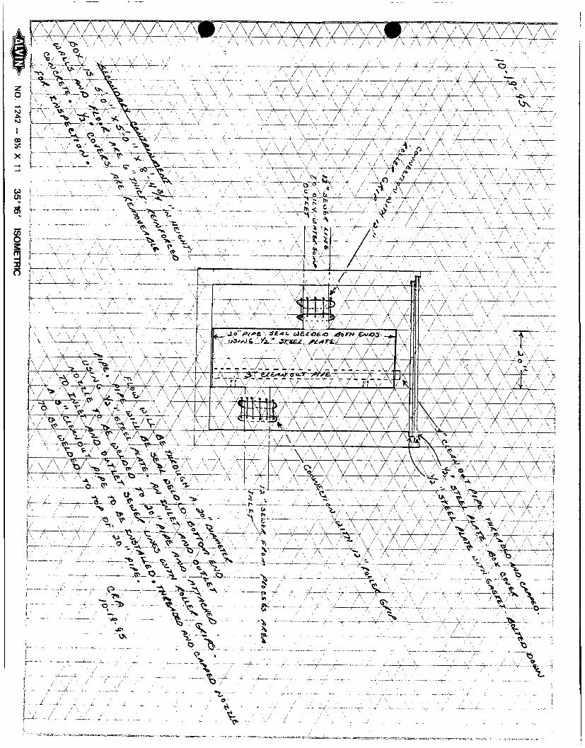
RE: CLEAN-OUT BOX AT LEA REFINING CO., LEA COUNTY NM
Dear Mark,
Enclosed is a copy ofthe drawing of the revised clean-out box at Lea Refining. As a you can see, we now have secondary containment and the lid can be lifted to check the annulus for leaks. However, we would like to bring to your attention the fact that the influent through the primary containment is hot. We are sure this will lead to condensation and some water in the secondary containment. This should be easy enough to distinguish from an oily leak.
I hope this addresses your concerns and we are sorry for any oversights on our part. I f you have any questions, please call me at 505-748-3311.
Sincerely, NAVAJO REFINING COMPANY
Darrell Moore Sr. Environmental Specialist
Encl.
An Independent Refinery Serving ... NEW MEXICO ° ARIZONA ° WEST TEXAS
-%/ \A/y\AA/\ / \A#7^ $ v v v \ - >
3p*__ f . . . V V- V v
Z7\ / \ / \ / \ A'/ A" ,\ X x X -X-
-f
• x ~Xr-
7X V"*.
l c , — : f > — ;
rrv' \ / -x-
,/\ /r / - r% 7\~7\
__SL. / "\» "\ /~ -'— '• ~ ~ ~ ~ \ _ _ ,
- 1 T;—
-V -V
\
7^ y.
~*f—
>w X
A -v* *
V

TELEPHONE (505)748-3311
EASYLINK 62905278
EEFIMIMG COMPANY (505) 746-6410 ACCTG (505) 746-6155 EXEC (505) 748-9077 ENGR (505) 746-4438 P / L
FAX
501 E A S T M A I N S T R E E T ° P. O . B O X 159 «.;,• ' ARTESIA. NEW MEXICO 88211 -0159
L'3 un r;P| 8 S^January3,1995
Mr. Roger Anderson Oil Conservation Division Environmental Bureau Land Office Bldg. P.O. Box 2088 Santa Fe, NM 87501
RE: Modification to Discharge Plan, Lea Refining Co., Lea County, New Mexico
Dear Roger,
As you are aware, Lea Refining Company is currently using a reverse osmosis process to treat our feed water into the plant. The reject water off of this unit is presently being sent to the City of Lovington's publicly owned treatment works(POTW). In order to halt this unnecessary treatment of perfectly good water, we have entered into a tentative agreement with Greenhill Petroleum to beneficially use this water as makeup for their secondary recovery efforts in the vicinity of the refinery.
To facilitate this project, Navajo is now seeking a modification to our discharge plan to allow us to discharge the above referenced waters through a 4" poly pipe to Greenhill's battery which is located approximately one mile southwest of the refinery. According to the agreement, Navajo is responsible for the piping within our fences and Greenhill is responsible from our fence to the battery. The piping will be engineered so that in the event of a problem where Greenhill could not take the water, it could be diverted back to Lovington's POTW. Volumes will run about 175000 gallons a day or 120 gallons a minute.
I have enclosed the analysis of the reject water for your review. We would like to start construction of the pipeline as soon as possible. To that end, if you agree with this proposal, we would appreciate it i f you could give us verbal approval pending written approval. Let me know if there is anything we can do to speed this process along. Thank you for your time in this matter.
Sincerely,
Darrell Moore Environmental Specialist
Encl.
An Independent Refinery Serving . .NEWMEXICO ° ARIZONA ° WEST TEXAS

lit o i J
- s 0
«* •«# b o 0 J) » « g 0
O Q ( j r S J M M « r | ffl
5 5 5 5 > o a c o 3
I . . . ' i>M> M to -H 0 0 o
f
ao
1 ' C
n
"1 (•„'!!
' l j A It I 1 ! <»' till IM
M O
s r-l
I S „ s W B Pj
| g s ° 00 03
i*» '-y.* «Hfe S3; 2 o se ^
•3 £*' ® 0 § ^ JJ o § SS < S rtj'
0>
',6* ;
; J ® • O 4 J
•• ''Be o 0 ' A • •*
<* M a 4* Ov Q ffi ••
Q« O ~
M > + > 4J
l-,CN->. 0 o o
,; . H . o o >« 0 - f t - n H-> r-4 o a o o 9 © a u u
• r> K to (u..
t1 n •! rt
•fc I
3 I
2
« <
M
I
iO 00
o o *' •
o in
S3 ^ IO •
< *r I,
U) to O rt
* •
o tn
O CM O O
o o, v
r • .
o 2
•no;*' o •
o •P (4 o +» 0 c 1
Tt.i.Q,
<9 *
CN CN Q i ro CN 8
m o o
H O
in O
¥
a
o o
tn o
H
W , 'K
H Q
o> tn
r4 °V
rH O
o o
m on o H
o u, rt <-l °* rH
tn n . w rH * " rH
O P
o,
o *n o o H I rH
o
rH O
Pi
S * H
> • > 1
M.-'.'M'.
O
o ** c. 0
• r l
I
0 ; N H , -,W.
id S 0 .
<» # #
o
0-
»
5
I
rt * O
o g * g o i rC rH rH « g
r H , 4
o o f •
o o rt CO
r- ° ? o oo in o w o o
* , 1 •
o o
9 *
? CN o o
in
m
Q.i.35 in
in
O o
CN
in
* o rt o
a 1 ~ a i
rt
8
8
. rt
o ro
rH ,
O v '
!° o
o
o o
i n , - r 1
Q l ,
in o
tn o
in o
. CO
o
.r-l
P
( I, '
I'M-X H rl
s M
t •B w p
* «> <D,
o» eh oo!
O _» rt
° A ° f i m rH
S *> S ° a\ ° H < " H
o
n
3
' i f f: l " " t i " ' I
I

•iTTft"'
ir ' "' •£ «. r, „ «
s g s .. O **s. it. £
^ CO ti
.«v,\. g e « R .. •• • •« -rl 0
0 0 4J :>. +» i,p -rr>3> m.
i A T I 111° >i< ,7*
•1 IIS " t o Rl
tn'i.j
CM: :!> ©• o O • ri «-». at.
r t I r ! Q| T V f - » ,H o e o o 3 9 9 vi tt b « co a, o,
1 Ss W O —
» Q
Si?
ro H
i i
[Ch I r-l I CM I
• CM
I CO
CM
rt © [in o
I o o I-:, •
. .1 '
8* hfc a*
o to W O
«
tv,
o V Q;
f co «* I co in
I.CM in \*f (*><•• I in CM i" * •* CM rt.
h © U
•s a. IcM l CM I O
IBS
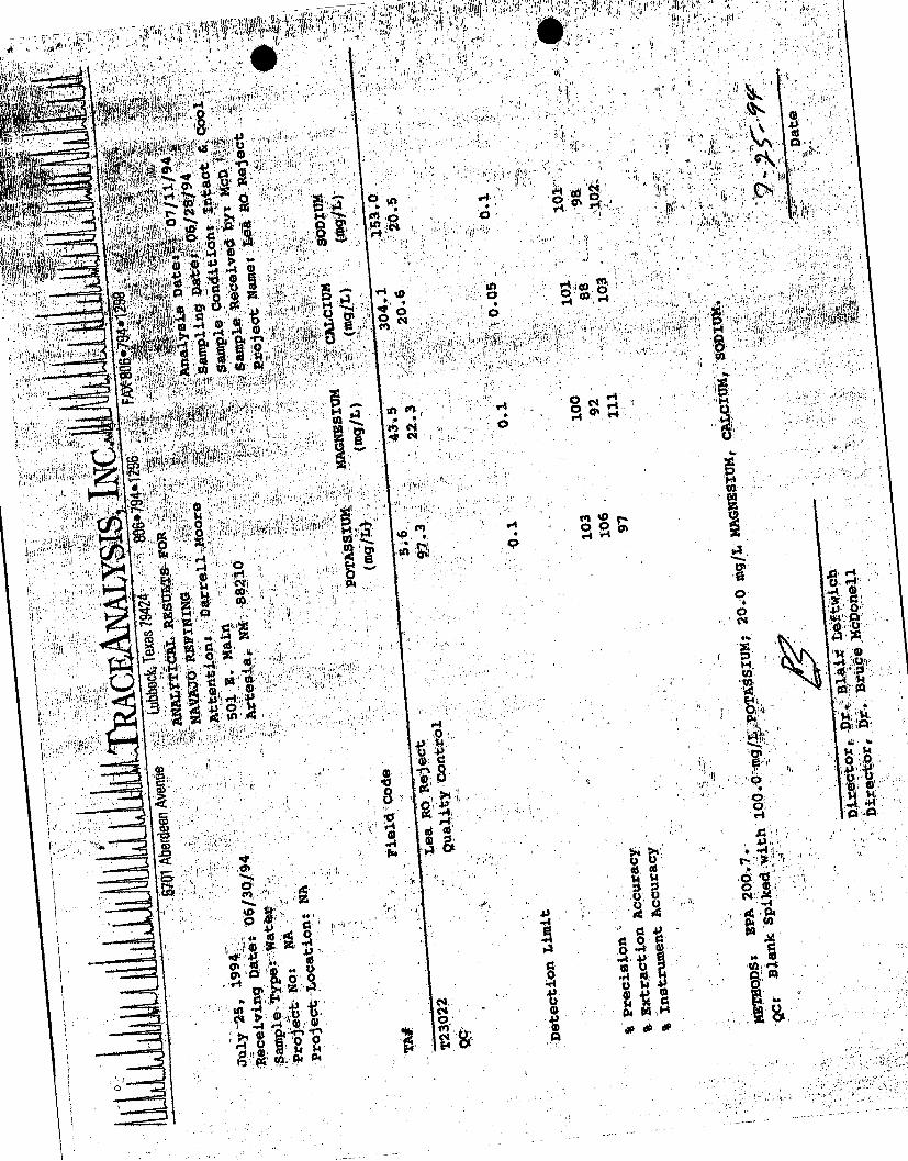
4 r,>
WIS rH
si 4»i
aa ^
^ 21 5 se ^
® *». 5 n> Pi!
a) w •
1 f 1 s K 5 g ! ! o> o PS
5 a w •» D n —i * » „ « B °, g1
JBS^Bi i j I Q i Q | n v
1 1
ro
tit
til
rt CN CO CO
a CP :
* 5 -''E n I» • rt
9 8
o
ro
O v c
. ..... n a %
rt
©
.ft* ft*
i1 ' >\ Hj V ' \
"I
t i
' i rt a, p»
•-4 rt CO 0 © CO
H * rt
ro £ t-S rt *
a
«• s
o u * ?. o, u rt <
C 0 (3 O rt |
*o o ? rt * H 0 Vl
tu W rt OP # #
5 H
I CO
rt to
s
U> I

") 6701 Aberdeen Avenue
lubbock. Texas 79424 ,
^ 8p6«794*1296
KAX806«794»1298
Analytical Results for NAVAJO REFINING Attention: Darrell Moore 501 K. Main Artesia, NM 88210
Project Name: LEA, RO Reject J u l y 25," 1994 „ ,
Date of Date of BOD5 TSS pfl Cl2 S A M P f * ^ F I * $ * U ™ * r e i v i n g Analys i s ( r a g / L ) ( m g / L ) ( 8 . u . ) <mg/L>
NH3-N (mg/L)
T23022 .»•-'"Lea RO Reject 06/30/94 07/01/94 <3
1
7.76 <0.1 <0.01
QUALITY CONTROL SUMMARY
BODS Precision » 98% BOP5 Instrument Accuracy = 108% TSS Precision » 99% pH precision = 100%
Director, Dr. Blair Leftwich Director, Dr. Bruce McDonell
DATE
llitiiMj^ Inc. A Laboratory for Advanced Environmental Research and Analysis

I 806*794# 1296 ' ' "
j I 1
r ' i f f ,„,/
it
J^ 'Oate .
^ Nama^Ro Refec t , ^
' 1 i
' i l l 1 fw
arte
/Nftrobenzemj , ,
I'spphOfone
/2,4-Oichtorop/,eno<
P*Cf)forcflaphlha/ete
Mcenapfrtheng
/2.4-Ofnftropheno,

NAVAJO REFINING ^ J u l y 25,1,994 ^ ' i - -
i';';T23022 ;/. i,?f. ,;4. i ! „'•;• LeaiROr
• JX-
Page 2 of 2
; •g.-4;r.;DL>:1:1 vt.:.;y:;i Reject QC %P i %EA %IA I-/ 0.464< NR NR
'6.doi :• ND
; : ND
0.529 . NR NR
0.522' NR' NR O.QOl ND 0.496 NR NR
rt^lttosodlphenytamine
Diphehylhydrazlne
0.001 ND 1.015 NR NR 0.005 ND 0.466 NR NR 0:001' ND 0.515 NR NR
Hexachlorobenzene
Pentachlorophenol
Plienanthrejie'
Anthracene.
FJiior&nthene.'. •
0.001 ND 0.513 NR NR 0.005 ND 0.486 99 95 0.001 ND 0.522 NR NR
; 0.001 ND 0.507 NR NR 0:001 •„y o.oo4 0.491 NR NR
dine
0,001 ND 0.510 NR NR 0.01 ND 0.558
Pyrene .** . . ; :
Jutyfperi^phlral^
Ben^ajantiiracene
3>D|c^l6ri9b^jne ••' .".
Chyreene S\ V "•
bls(2^ylh^phthaWte. * X.
DkKictlphthalate • .V ;.. ^
3enzo[b]fluorarithene •
Benzo[k]fluoranthene
Benzo[a]pyrene s .f '
Ir^r-all J^pjr^e- I f t ^ -f^J " ''
Diben2fa,h"lar^rac»rie '. 1%% •
Benzo[g,h,Operylerie" . y ; E ^flf:!.,, jn' y
0.004 il' '|( 0.499
NR NR
99 124
Mm ND 0.477 0.001' ND 0.495
NR. NR
NR NR 0.001
0.001 ND 0.477, NR NR 0.474:
0.001 0,001 0.480
NR
NR
NR
NR! ,0.001, ND 0.493 NR NR 0.001 ND 0.459 0.001 ND 0.499
NR
NR 0.001 ND 0.487 NR
NR
NR
NR
0.001
; ' • • I
jsjp_ 0.451 NR NR ND 0.430 NR NR
0.422 NR NR
93c
105
104
99
102
93
103
102
97
104
101
98
102
102
112
100
94
99
95
96
99
92
100
97,
90
86
84 ND> Not Detected rl "jV sf-y-.^. •!!;«''-J
;/:'y' ' ;;"*•'• ;VT:; : v"- |r?::'.!; %'RECOVERY 2-FiubrophenolSURR, - • .'.,„;;. 88 *"
PhenoW5 $URR r ?
Nitrobenzene-dS SURR
2-Fluorobfphenyt SURR !
2,4,6-Tribrorrtpphenol SURR
Terphenyt-dUsORR.
METHODS: E P A 625. :
. 'i - 87
88
93
87
99
Director,'; Dr. Blair Leftwich ^° Dr. Bruce McDonell
DATE

67.(11: Aberdeen Avenue1- rt, • 1 ' : u'.:"'" t
Lubbock; Texas 79424 1
806»794«t296
FAX 806«794*1298
Vu- I'
July 25, 1994 Receiving Date: 06/30/94. Sample Type: Water Project No: NA Project Location: Artesia, NM
ANALYTICAL RESULTS FOR NAVAJO REFINING . Attention: Darrell Moore ; 501 E. Main . ^ Artesia, NM 88210 Analysis Date: 07/13/94
. Sampling Date: 06/28/94 Sample Condition: I S C Sample Received by: McD Project Name: Lea RO Reject
ORGANOCHLORINE INSECTICIDES (mg/L)
T23022 Lea RO Reject
Detection Limit QC %P %EA %IA
a-BHC ND 0.003 0.0006 100 93 80 b-BHC ND 0.006 0.0008 90 120 ld7 g-BHC ND 0.004 0.0009 88 119 120 S-BHC ND 0.009 0.0008 94 119 107 Heptachlor • ND 0.003 0.0010 100 80 133 Al d r i n : ND 0.004 0.0009 '• 1.8.8, 1P7 120 Heptachlor epoxide . ND 0.004 0.0009 86 125 120 Endpsulfan-l ND 0.005 0.0009 100 80 120 EndosuIfan-2 ND 0.004 0.0008 90 125 107 DDE , .. ND 0.004 0.0007 ,80 125 93 Di e l d r i n ND . 0.002 0.0007 80 125 93 Endrin ...!'••' ,n : ND 0.006 0.0007 93 80 93 DDD ND 0.005 0.0006 88 119 80 Endrin Aldehyde ND 0.01 0.0007 , 95 119 93 Endosulfan Sulphate ND 0.05 0.0007 93 93 93 DDT ND 0.005 0.0007 80 125 93 Methoxychlor i ND 0.01 0.0010 100 80 133 PCB's .. ;;;r' Ki :,t I- ND 0.001 r — — —
Chlordane :,. •; -:i•['[-• . ; ND 0.0002 0.0021 100 105 ; 105 Toxaphene ." lj!*, - ' ' ' " l v ! v • ND 0.005 0.0208 99 1 84 ,; ! 104 ND =' Not. Detected' i ' ' ' ' ' i ii. • ]'"'-, •
METHODS: EPA 608.
Director, Dr. B l a i r Leftwich Director, Dr. Bruce McDonell
DATE
,YSIS. INC A Laboratory for Advanced Environmental Research and Analysis
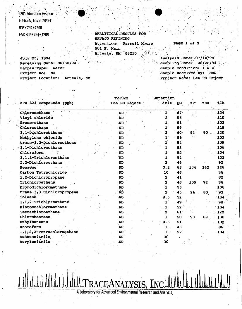
67Q1 Aberdeen Avenue
Lubbock, Texas 79424
806»794»1296
FAX 8Q6»794»1298 ANALYTICAL RESULTS FOR NAVAJO REFINING Attention: Darrell Moore 501 E. Main Artesia, NM 88210 ];, y»r.;t
July 25, 1994 , Receiving Date: 06/30/94 Sample Type: Water Project No: NA Project. Location: Artesia, NM
PAGE 1 Of 2
Analysis Date: 07/14/94 Sampling Date: 06/28/94 . Sample Condition: I & C Sample Received by: McD ' Project Name: Lea RO Reject
EPA 624. Compounds (ppb) T23022
Lea RO Reject Detection
Limit QC %P %EA %IA
Chloromethane 1 ' ND 1 67 134
Vinyl chloride ND 2 55 110 Bromomethane ND 1 51 102 Chloroethane ND 1 59 118
1,1-bichloroethene ND 2 60 94 90 120 Methylene chloride ND 1 51 102 trans-1,2-Dichloroethene ND l " 54 108 1,lrDichloroethane ND '•' 1 53 106
Chloroform ;• • ND 1 52 104
1,1,1-Trichloroethane ND 1 51 102 1,2-Dichibrpethane . ' ND 2 46 92 Benzene - ND 0.2 63 104 142 126 Carbon Tetrachloride ND 10 48 96 1,2-Dichloroprppane ND 2 41 82 Trichloroethene ND 2 48 105 92 96 Bromodichloromethane ND 1 53 106 trans-1,3-Dichloropropene ND 2 46 94 80 92 Toluene ND 6.5 52 104 1,1;2-Trichlbroethane ND 1 49 98 Dibromochloromethane ND V : 1 52 104 Tetrachloroethene ND 2 61 , 122 Chlorobenzene ND 1 50 93 89 100 Ethylbenzene ND 0.5 51 102 Bromoform ND 1 43 86 1,1,2,2-Tetrachloroethane ND 1 52 104 Acentonitrile ND 30 A c r y l o n i t r i l e ND 30
ilJLlM^^ INC A Laboratory for Advanced Environmental Research and Analysis.

»*1 ' !
f^ EPA 624 Compou
lPP b>
1 i
!• I'll . 0 - '
• • i i -n
» « 'a'ii'''^!''
• ' ..i'-jij;'*' I 1
%1 RECOVERY i 1 t ^ i
100 120
HU'. l l ' " " " t . t"
« 4 F * »
•m.
• ' i " 1 ' ' ' ' ' - l i l l >» l u .
','W1'/ J" ' : t i l
h ,
i « ,
t1 w i ! l
1 1 »©'
TV£.•:•% «... •..-»
* I ! 1 "
w T
i * i it b 1
1 l i l »
1 a
, 1 1 , I' ' . ' » / '
111!
1'| - | i ti i *
D i r e c t o r , D r . uruv.
DATE
I i
i 1 \
i !
, i A *
1 %

May 19, 1993
STATE OF NEW HEXICO
ENVIRONMENT DEPARTMENT
Bruce King Governor
Judith M. Espinosa Secretary
Ron Curry Deputy Secretary
Harold Runnels Building 1190 St. Francis Drive
P.O. Box 26110 Santa Fe. Wf 87502 M (SOS) 827-2850 FAX (505) 827-2836
Mr. William R. Koym SLCU/Law Department The Travelers Companies 1201 Louisiana, Suite 3300 Houston, TX 77002
Dear Mr. Koym:
I am referring your letter, dated May 7, 1993, regarding Southern Union Company Lovington Refinery to the Surface Water Bureau and the Hazardous and Radioactive Materials Bureau of the Environment Department, and to the Oil Conservation Division of Energy and Minerals Department for their response to you.
The Ground Water Protection and Remediation Bureau does not have a record on the Southern Union Company Lovington Refinery.
I f you have any questions, please contact Jim Piatt of Surface Water Bureau, (505) 827-0187, Benito Garcia of Hazardous and Radioactive Materials Bureau (505) 827-4300, and Roger Anderson of the Oil Conservation Division, (505) 827-5800.
Sincerely,
Steve Cary, Chief Ground Water Protection
and Remediation Bureau
cc: Jim Piatt, Surface Water Bureau Benito Garcia, Hazardous and Radioactive Materials
Bureau Roger Anderson, Oil Conservation Division

RECEIVED
TheTravelersj MAY141K3
The Travelers Companies Special Liability Coverage Unit 1201 Louisiana Suite 3300 GROUND WATPK a I ID^ Law Department Houston. TX 77002 " tffcrt I GUf l lL,
Steve Cary, Bureau Chief May 7, 1993 Groundwater Protection and
Remediation Bureau Environmental Improvement Division 1190 St. Francis Drive, Room North 2261 Santa Fe, New Mexico 87502
Site : Southern Union Company Lovington Refinery
Location : Lovington, NM
Dear Mr. Cary:
Under the Freedom of Information Act of your state I am requesting access to and copies of information regarding the above s i t e located i n Lovington, New Mexico. I would ask that you have a department-wide search for a l l material that i s public record f o r t h i s f a c i l i t y and that material be made available to me f o r my review.
My goal i s to develop a clear chronological picture of the problems that have transpired at t h i s s i t e s t a r t i n g i n 1973 u n t i l the s i t e was purchased by Holly Corporation/Navaho Refining Company i n 1989.
I f you deny any or a l l parts of t h i s request, please c i t e each sp e c i f i c exemption you think j u s t i f i e s your refusal t o release the information and n o t i f y me of appeal procedures available under the law.
After t h i s l e t t e r has been assigned to the appropriate project manager, please ask that manager to contact me so th a t arrangements can be made for me to v i s i t your o f f i c e f o r the purpose of reviewing the above f i l e . I f there are questions concerning t h i s request, please contact me at (713) 650-8766.
Sincerely,
William R. Koym SLCU/Law Department Houston, Texas
WRK:vmw/scary.bk
HOME OFFICE One Tower Square Har t f n r r l C T 0 6 1 8 3

ENVIRONMENT DEPARTMENT
BRUCE KING GOVERNOR e T ^ j
JUDITH M. ESPINOSA SECRETARY
RON CURRY DEPUTY SECRETAR Y
FEB 1 5 1993 OIL CONSERVATION DIV.
SANTA FE
February 10, 1993
Mrs. Buck Whitaker 9 01 East Avenue R Lovington, New Mexico 88260
Re: Navajo Refinery's Lea F a c i l i t y at Lovington, NM
Dear Mrs. Whitaker:
Thank you for your l e t t e r of January 20, 1993, concerning the Lea Refinery i n d u s t r i a l waste discharge through the City of Lovington's c o l l e c t i o n system to the City's wastewater treatment plant.
I understand that a dir e c t pipeline from the refinery to the wastewater treatment plant i s under construction r i g h t now, and should be placed i n service sometime t h i s month. This should resolve the problems you mentioned of refinery waste odors and excessive flows i n the c o l l e c t i o n system, as the l i n e does not go through the City. This e f f o r t towards a voluntary resolution to the problems i s to be commended. However, there may s t i l l be problems with the refinery wastes at the wastewater treatment plant, which the City of Lovington i s responsible for and w i l l have to resolve.
The US Environmental Protection Agency i s involved with t h i s s i t u a t i o n , and has s t a f f assigned to evaluate Navajo Refinery's compliance status under the federal Clean Water Act. The Surface Water Quality Bureau assists the US Environmental Protection Agency i n t h e i r e f f o r t s towards the resolution of t h i s problem.
N<.H<^. /I// = DRUG FREE =
IIII Harold Runnels Building • 1190 St. Francis Drive • P.O. Box 26110 • Santa Fe, New Mexico 87502
f^fl^ On ">C<rn A ir ,c-r\r\ n"- ~r~-r

Mrs. Buck Whitaker February 10, 1993 Page 2
Thank you f o r expressing your concerns. I hope t h i s i n f o r m a t i o n w i l l be b e n e f i c i a l t o you. I f we can be of f u r t h e r assistance, please c a l l Ann Young of my s t a f f a t (505) 827-2823.
Sincerely,
Jim P i a t t Chief Surface Water Q u a l i t y Bureau
pc: Bob Carter, C i t y Manager, C i t y of Lovington David G r i f f i n , Superintendent of Environmental A f f a i r s and
Qu a l i t y Control, Navajo Ref i n i n g Company Garry McCaslin, Manager, NMED D i s t r i c t IV, Roswell Tom Burt, Carlsbad O f f i c e , NMED Myra Myers, Hobbs O f f i c e , NMED Robert Garcia, Ground Water P r o t e c t i o n and Remediation Bureau,
NMED B i l l Olsen, O i l Conservation D i v i s i o n

NOTICE OF PUBLICATION
STATE OF NEW MEXICO ENERGY, MINERALS AND NATURAL RESOURCES DEPARTMENT
OIL CONSERVATION DIVISION
Notice is hereby given that pursuant to New Mexico Water Quality Control Commission Regulations, the following discharge plan applications and renewal applications have been submitted to the Director of the Oil Conservation Division, State Land Office Building, P. O. Box 2088, Santa Fe, New Mexico 87504-2088, Telephone (505) 827-5800:
(GW-85) - Union Oil Company of California, DBA UNOCAL, Glen O. Papp, District Production Engineer, 3300 North Butler, Suite 200, Farmington, New Mexico 87401, has submitted a discharge plan application for its Navajo Compressor Station located in the NW/4, NW/4, Section 7, Township 25 North, Range 10 West, NMPM, San Juan County, New Mexico. Approximately 4 gallons per day of washdown water and natural gas liquids will be collected in a double lined pond equipped with leak detection prior to disposal at an OCD approved offsite disposal facility. Groundwater most likely to be affected by an accidental discharge is at a depth in excess of 100 feet with a total dissolved solids concentration of approximately 700 mg/l. The discharge plan addresses how spills, leaks and other accidental discharges to the surface will be managed.
(GW-86) - BCO, Inc., Elizabeth B. Keeshan, President, 135 Grant, Santa Fe, New Mexico, 87501, has submitted a discharge plan application for its North Lybrook Compressor Station located in the SE/4 SE/4, Section 2, Township 23 North, Range 7 West, NMPM, Rio Arriba County, New Mexico. Approximately 14 gallons per day of wastewater will be stored in an above-ground fiberglass tank prior to disposal in an OCD approved offsite disposal facility. Groundwater most likely to be affected by an accidental discharge is at a depth of approximately 225 feet with a total dissolved solids concentration of approximately 1470 mg/l. The discharge plan addresses how spills, leaks and other accidental discharges to the surface will be managed.
(GW-75) - HOMCO International, Inc., Robert J . Meddler, Director, Environmental and Safety, P. O. Box 2442, Houston, Texas 77252, has submitted a discharge plan application for its Hobbs service facility located in Section 29, Township 18 South, Range 38 East, NMPM, 3000 West County Road, Lea County, New Mexico. Approximately 800 gallons per day of wastewater are presently stored in an above ground storage tank prior to disposal in an OCD approved offsite disposal facility. Proposed modifications include the installation of a wastewater recycling system. Unrecyclable wastes will be stored in below grade concrete sump equipped with leak detection prior to disposal at an OCD approved offsite disposal facility. Groundwater most likely to be affected by an accidental discharge is in the Ogallala aquifer at a depth of 55 feet with a total dissolved solids concentration ranging fro 300 mg/l of 700 mg/l. The discharge plan addresses how spills, leaks and other accidental discharges to the surface will be managed.

(GW-72) - The Western Company of North America, Ron McKeel, Director, Real Estate and Facilities, 515 Post Oak Blvd., Suite 915, Houston, Texas 77027, has submitted a discharge plan application for its Hobbs service facility located in the NE/4, Section 20, Township 18 South, Range 38 East, NMPM, Lea County, New Mexico. Approximately 3350 gallons per day of wastewater with a total dissolved solids concentration of 3942 mg/l is stored in below grade fiberglass tanks prior to disposal at an OCD approved offsite disposal facility. Groundwater most likely to be affected by an accidental discharge is in the Ogallala aquifer at a depth of approximately 55 feet with a total dissolved solids concentration of ranging from 300 mg/l to 700 mg/l. The discharge plan addresses how spills, leaks and other accidental discharges to the surface will be managed.
(GW-76) - Star Tool Company, David T. Taylor, Vice President, P. O. Box 2008, Hobbs, New Mexico 88240, has submitted a discharge plan application for its Hobbs service facility located in the NE/4 NW/4, Section 32, Township 18 South, Range 38 East, NMPM, Lea County, New Mexico. Approximately 10 gallons per day of wastewater are currently stored in unlined pits prior to disposal at an OCD approved offsite disposal facility. Proposed modifications include the installation of a wastewater recycling system. Unrecyclable wastes will be collected in above ground tanks prior to disposal at an OCD approved offsite disposal facility. Groundwater most likely to be affected by an accidental discharge is at a depth of 44 feet with a total dissolved solids concentration ranging from 300 mg/l to 700 mg/l. The discharge plan addresses how spills, leaks and other accidental discharges to the surface will be managed.
(GW-73) - Dowell Schlumberger, Inc., M. L. Wood Jr., Environmental Coordinator, 1105 West Bender Street, Hobbs, New Mexico 88240, has submitted a discharge plan application for its Hobbs service facility located in the NE/4 NE/4, Section 28, Township 18 South, Range 38 East, NMPM, Lea County, New Mexico. Approximately 2200 gallons per day of wastewater is stored in above grade tanks and lined pits prior to disposal at an OCD approved offsite disposal facility. Proposed modifications include the installation of a wastewater recycling system and closure of all surface impoundments. Wastes not recyclable will be disposed of at an OCD approved offsite disposal facility. Groundwater most likely to be affected by an accidental discharge is at a depth of 68 feet with a total dissolved solids concentration ranging from 300 mg/l to 700 mg/l. The discharge plan addresses how spills, leaks and other accidental discharges to the surface will be managed.

(GW-14) - Navajo Refining Company, David G. Gnmh, Superintendent, Environmental Affairs, P. O. Box 159, Artesia, New Mexico 88210, has submitted a discharge plan renewal application for its Lovington Refinery located in the SW/4, Section 31, Township 16 South, Range 37 East; the SE/4 of Section 36, Township 16 South, Range 36 East; the NW/4 of Section 6, Township 17 South, Range 37 East; and the NE/4 of Section 1, Township 17 South, Range 36 East, NMPM, Lea County, New Mexico. Approximately 175,000 gallons per day of process wastewater with a total dissolved solids concentration of 1300 mg/l will undergo treatment in a USEPA regulated pretreatment unit prior to discharge to the City of Lovington sanitary sewer system. Groundwater most likely to be affected by an accidental discharge is at a depth ranging from 60 feet to 80 feet with a total dissolved solids concentration of 450 mg/l. The discharge plan addresses how spills, leaks and other accidental discharges to the surface will be managed.
Any interested person may obtain further information from the Oil Conservation Division and may submit written comments to the Director of the Oil Conservation Division at the address given above. The discharge plan application may be viewed at the above address between 8:00 a.m. and 5:00 p.m., Monday through Friday. Prior to ruling on any proposed discharge plan or its modification, the Director of the Oil Conservation Division shall allow at least thirty (30) days after the date of publication of this notice during which comments may be submitted to him and public hearing may be requested by any interested person. Requests for public hearing shall set forth the reasons why a hearing should be held. A hearing will be held if the Director determines there is significant public interest.
If no public hearing is held, the Director will approve or disapprove the proposed plan based on information available. If a public hearing is held, the Director will approve or disapprove the proposed plan based on information in the plan and information submitted at the hearing.
GIVEN under the Seal of New Mexico Oil Conservation Commission at Santa Fe, New Mexico, on this 5th day of August, 1991.
STATE OF NEW MEXICO OIL CONSERVATIONJDIVISION
S E A L

#
OIL CONSERV REC
ifi DIVISION 'ED
July 17, 1991 '91 JUL 2h nn 9 11 TO BE PUBLISHED ON OR BEFORE JULY 27, 1991
PUBLIC NOTICE
NEW MEXICO ENVIRONMENT DEPARTMENT
Notice i s hereby given that, pursuant to New Mexico Water Quality Control Commission Regulations, the following proposed discharge plans have been submitted f o r approval to the New Mexico Environment Department. The information i n t h i s notice generally has been supplied by the applicant and may or may not have been confirmed by the Environment Department.
DP-87 CITY OF LOVINGTON, Bob Carter, City Manager, P.O. Box 1269, Lovington, NM 88260, proposes to modify i t s discharge plan for the discharge of up to 1.5 m i l l i o n gallons per day (MGD) of treated municipal ef f l u e n t to a land application s i t e . The f a c i l i t y i s located i n Lovington i n Section 10, 11 and 14, T16S, R36E, Lea County. The proposed modification i s for addition of 0.17 MGD to the treatment plant from the Navajo refinery. The estimated q u a l i t y of the waste water from the refinery i s : COD, 1056 milligrams per l i t e r (mg/l); CL, 505 mg/l; TKN, 20 mg/l; SO4, 292 mg/l and TDS, 1300 mg/l. I t i s estimated that additional 50 to 120 acres of cropland w i l l be needed at the land application s i t e for the additional flow from the refinery. Ground water below the s i t e i s at a depth of approximately 60 fe e t and has a t o t a l dissolved solids concentration of approximately 700 mg/l. ~
DP-398 EILEEN ACRES MOBILE HOME PARK, James L. Wimberly, Owner, P.O. Box 130, Alto, NM 88312, (505) 336-4377, proposes to renew i t s discharge plan for the disposal of up to 41,300 gallons per day of domestic sewage eff l u e n t from a package waste water treatment plant. The f a c i l i t y i s located near La Luz on U.S. 54 i n the NE 1/4 of Section 33, T15E, R10E, Otero County. The ef f l u e n t w i l l be i r r i g a t e d using sprinklers onto 5.6 acres of bermuda grass. : Ground water below the s i t e i s at a depth of approximately 230 feet and has a t o t a l dissolved solids concentration of approximately 1,800 milligrams per l i t e r .
DP-419 US INTERIOR - CHACO CULTURE NATIONAL PARK, Bonnie Winslow, Acting Superintendent, St. Rt. 4, Box 6500, Bloomfield, NM 87513, proposes t o renew i t s discharge plan which allows the discharge of up to 15,000 gallons per day of domestic sewage. The f a c i l i t y i s located approximately 40 miles south of Bloomfield i n Section 21, T21N, R10W, San Juan County. Domestic septage and r e j e c t water from a reverse osmosis u n i t i s pumped to a series of synthetically-lined sewage lagoons f o r evaporation.
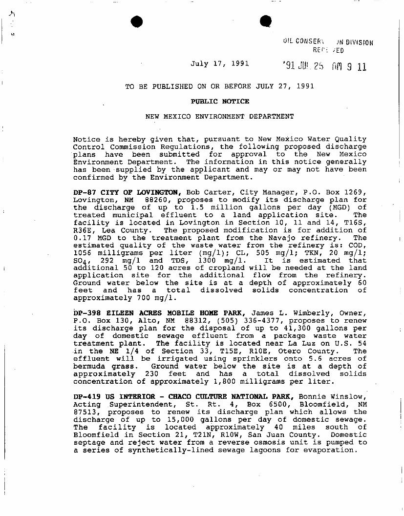
OIL CONSERV JN DIVISION RECI vED
July i?, 1991 '9i ju«.2s nn 9 11 TO BE PUBLISHED ON OR BEFORE JULY 27, 1991
PUBLIC NOTICE
NEW MEXICO ENVIRONMENT DEPARTMENT
Notice i s hereby given t h a t , pursuant t o New Mexico Water Quality Control Commission Regulations, the f o l l o w i n g proposed discharge plans have been submitted f o r approval t o the New Mexico Environment Department. The information i n t h i s notice generally has been supplied by the applicant and may or may not have been confirmed by the Environment Department.
DP-87 CITY OF LOVINGTON, Bob Carter, C i t y Manager, P.O. Box 1269, Lovington, NM 88260, proposes t o modify i t s discharge plan f o r the discharge of up t o 1.5 m i l l i o n gallons per day (MGD) of tre a t e d municipal e f f l u e n t t o a land a p p l i c a t i o n s i t e . The f a c i l i t y i s located i n Lovington i n Section 10, 11 and 14, T16S, R36E, Lea County. The proposed m o d i f i c a t i o n i s f o r a d d i t i o n of 0.17 MGD t o the treatment plant from the Navajo r e f i n e r y . The estimated q u a l i t y of the waste water from the r e f i n e r y i s : COD, 1056 milligrams per l i t e r (mg/l); CL, 505 mg/l; TKN, 20 mg/l; SO4, 292 mg/l and TDS, 1300 mg/l. I t i s estimated t h a t a d d i t i o n a l 50 t o 120 acres of cropland w i l l be needed at the land a p p l i c a t i o n s i t e f o r the a d d i t i o n a l flow from the r e f i n e r y . Ground water below the s i t e i s at a depth of approximately 60 f e e t and has a t o t a l d i s s o l v e d so l i d s concentration of approximately 7 00 mg/l.
DP-398 EILEEN ACRES MOBILE HOME PARK, James L. Wimberly, Owner, P.O. Box 130, A l t o , NM 88312, (505) 336-4377, proposes t o renew i t s discharge plan f o r the disposal of up t o 41,300 gallons per day of domestic sewage e f f l u e n t from a package waste water treatment p l a n t . The f a c i l i t y i s located near La Luz on U.S. 54 i n the NE 1/4 of Section 33, T15E, R10E, Otero County. The e f f l u e n t w i l l be i r r i g a t e d using s p r i n k l e r s onto 5.6 acres of bermuda grass. Ground water below the s i t e i s at a depth of approximately 230 feet and has a t o t a l dissolved s o l i d s concentration of approximately 1,800 milligrams per l i t e r .
DP-419 US INTERIOR - CHACO CULTURE NATIONAL PARK, Bonnie Winslow, Acting Superintendent, St. Rt. 4, Box 6500, Bloomfield, NM 87513, proposes t o renew i t s discharge plan which allows the discharge of up t o 15,000 gallons per day of domestic sewage. The f a c i l i t y i s located approximately 40 miles south of Bloomfield i n Section 21, T21N, R10W, San Juan County. Domestic septage and r e j e c t water from a reverse osmosis u n i t i s pumped t o a series of s y n t h e t i c a l l y - l i n e d sewage lagoons f o r evaporation.

Ground water below the s i t e i s at a depth of approximately 925 f e e t and has a t o t a l d i s s o l v e d so l i d s concentration of approximately 1,800 milligrams per l i t e r .
DP-429 LOS COLONIAS MOBILE HOME PARK, Elbert D. Martinez, Owner, 2801 V a i l Avenue, Redondo Beach, CA 90278-1530, proposes t o renew i t s discharge plan which allows f o r the discharge of 7,500 gallons per day of domestic waste water i n t o a septic tank-leach f i e l d system located 4 miles northwest of Taos i n Section 30, T26, R13E, Taos County. Ground water below the s i t e i s at a depth of approximately 60 feet and has a t o t a l dissolved s o l i d s concentration of approximately 300 mg/l.
DP-587 IDEAL MOBILE HOME PARK, LeRoy Huebner, Owner, 120 E. 1st, Clovis, NM 88101, proposes t o modify i t s discharge plan which allows the discharge of up to 6,000 gallons per day of domestic sewage t o a series of evaporation lagoons. The f a c i l i t y i s located approximately 8 miles northwest of Clovis i n the SW 1/4, Section 6, T3N, R35E, Curry County. The m o d i f i c a t i o n consists of c o n s t r u c t i n g a series of concrete sewage lagoons f o r treatment and evaporation of domestic waste from the Ideal Mobile Home Park. Excess c l a r i f i e d sewage supernate w i l l be used t o i r r i g a t e range land and ornamental trees on property adjacent t o the mobile home park owned by Mr. and Mrs. Wall and Mr. Tommie Tucker. Ground water below the s i t e i s at a depth of approximately 400 feet and has a t o t a l dissolved s o l i d s concentration of approximately 300 milligrams per l i t e r .
CORRECTION: DP-810 RANCHO ENCANTADO I n the pu b l i c notice published on or before July 5, 1991, the l o c a t i o n should have been Section 7, T18N, R10E. The complete, corrected notice f o l l o w s :
DP-810 RANCHO ENCANTADO, John T. Egan, Route 4, Box 57C, Santa Fe, NM 87501, proposes t o discharge approximately 50,000 gallons per day of t r e a t e d sewage e f f l u e n t from a re s o r t community. The f a c i l i t y i s located approximately 2.5 miles north of Tesuque i n the SW 1/4, SW 1/4, SE 1/4 of Section 7, T18N, R10E, Santa Fe County. The sewage w i l l be tre a t e d using a package treatment p l a n t which w i l l f a c i l i t a t e nitrogen removal. The t o t a l n i t rogen a f t e r treatment i s estimated t o be 10 milligrams per l i t e r (mg/l). The tr e a t e d e f f l u e n t w i l l be discharged t o a leach f i e l d . Ground water below the s i t e i s at a depth of approximately 170-300 fee t and has a t o t a l dissolved s o l i d s concentration of approximately 300 mg/l.
DP-811 CONTRACT CARRIERS, Mike H a r r i s , C o n t r o l l e r , 830 Broadway Blvd., NE, Albuquerque, NM 87102, proposes t o discharge 21,600 gallons per day of spray aerated, oxygenated water from a contaminated monitor w e l l to a bioremediation i n f i l t r a t i o n bed. The f a c i l i t y i s located i n Albuquerque i n the SW 1/4 of NE 1/4 of SE 1/4, Section 17, TION, R3E, B e r n a l i l l o County. The discharge w i l l e s t a b l i s h a b i o l o g i c a l l y a c tive zone i n the vadose zone between the i n f i l t r a t i o n system and the water t a b l e , thus
remediating the gasoline contaminated s o i l s . Ground water below the s i t e i s at a depth of approximately 45 feet and has a t o t a l dissolved s o l i d s concentration of approximately 500 milligrams per l i t e r .
DP-812 DONA ANA COUNTY LIQUID WASTE FACILITY, Frank S t e e l e , D i r e c t o r , Environmental Services Department, Dona Ana County, 2025 E. Griggs Avenue, Las Cruces, NM 88001, proposes t o discharge up to 30,000 gallons per day f o r a 5-day week of l i q u i d waste t o two geosynthetically l i n e d , t o t a l retention/evaporation ponds. The ponds w i l l be constructed w i t h leachate c o l l e c t i o n systems. The f a c i l i t y i s located about 1 1/2 miles northeast of the I n t e r s t a t e 1-10 Mesquite Interchange i n Section 32, T24S, R3E, Dona Ana County. Ground water below the s i t e i s at a depth of approximately 250 feet and has a t o t a l dissolved s o l i d s concentration of approximately 300-400 milligrams per l i t e r .
DP-813 CANYON KIDS CLUB DAY CARE CENTER, Vincent B o t a r e l l i , Property Owner, P.O. Box 939, Idaho Springs, CO 80452, proposes to discharge 2,300 gallons per day of domestic sewage from a day care center. The f a c i l i t y i s located i n T i j e r a s i n Section 22, T10N, R5E, B e r n a l i l l o County. Domestic sewage from the day care center w i l l be discharged t o a septic tank-leach f i e l d system. Ground water below the s i t e i s at a depth of approximately 70 f e e t and has a t o t a l d i s s o l v e d s o l i d s concentration of approximately 400 milligrams per l i t e r .
DP-814 BAYO WASTE WATER TREATMENT PLANT, Paul P i z z o l i , D i r e c t o r of Gas, Water, Sewer Operations, Department of Public U t i l i t i e s , County of Los Alamos, 901. T r i n i t y Drive, P.O. Box 1057, Los Alamos, NM 87544, proposes t o discharge 800,000 gallons per day of t r e a t e d e f f l u e n t from the Bayo Waste Water Treatment Plant. The e f f l u e n t w i l l be stored i n a l i n e d lagoon and used t o i r r i g a t e the County g o l f course and b a l l f i e l d s located 1 mile northeast of Los Alamos on North Mesa i n Section 4, T19N, R6E, Los Alamos County. Ground water below the discharge s i t e i s at a depth of approximately 850 feet and has a t o t a l dissolved s o l i d s concentration of approximately 250 mg/l.
Any i n t e r e s t e d person may obtain f u r t h e r information from the Ground Water Section of the Environment Department, telephone (505) 827-2906, and may submit w r i t t e n comments t o the Ground Water Section, Environment Department, P.O. Box 26110, Santa Fe, NM 87502. P r i o r t o r u l i n g on any proposed discharge plan or i t s m o d i f i c a t i o n , the Environment Department w i l l allow t h i r t y (30) days a f t e r the date of p u b l i c a t i o n of t h i s notice t o receive w r i t t e n comments and during which a public hearing may be requested by any in t e r e s t e d person. Requests f o r public hearing s h a l l set f o r t h the reasons why the hearing should be held. A hearing w i l l be held i f the Environment Department determines t h a t there i s s i g n i f i c a n t public i n t e r e s t .

T E L E P H O N E
( 5 0 5 ) 748-331 1
REFINING COMPANY 501 E A S T M A I N S T R E E T • P. O. D R A W E R 159
E A S Y L I N K
6 2 9 0 5 3 7 8 ~ -
F A X
( 5 0 5 ) 746-6410
ARTESIA , NEW MEXICO 8 8 2 I O
July 9, 1991
Mr. David G. Boyer, Chief Environmental Bureau Oil Conservation Division 310 Old Santa Fe Trail, Room 206 Santa Fe, NM 87501
RE: LEA REFINING COMPANY DISCHARGE PLAN
Dear Mr. Boyer:
Enclosed are three (3) copies of Lea Refining Company's Discharge Plan submittal. Navajo would like to restart the Lea Refinery in Lovington, NM in October of this year. Your prompt review of this application will be greatly appreciated.
If you have any questions concerning the application please give me a call at 748-3311, ext. 223.
Sincerely, / / / /
\
David G. Griffin Supt. of Environmental Affairs & Quality Control
DGG/pb
enclosure
An Independent Refinery Serving... NEWMEXICO • ARIZONA • WEST TEXAS
NAVAJO REFINING COMPANY
GROUND WATER DISCHARGE PLAN
LEA REFINERY, LOVINGTON, NEWMEXCIO
July 9, 1991
Prepared For:
New Mexico Oil Conservation Division
P.O. Box 2088
Santa Fe, New Mexico 87501-2088
Supt. Environmental Affairs & Quality Control

TABLE OF CONTENTS
1.0 EXECUTIVE SUMMARY 1
2.0 LOCATION, PURPOSE, RESPONSIBLE PARTIES AND BACKGROUND 2
2.1 LOCATION 2
2.2 PURPOSE 2
2.3 RESPONSIBLE PARTIES 2
2-4 BACKGROUND 2
3.0 ENVIRONMENTAL SETTING AND CONDITIONS 4
3.1 REGIONAL AND LOCAL HYDROGEOLOGY 4 3.3.1 Regional Hydrogeology 4 3.3.2 Local Hydrogeology 4 3.3.3 Local Wells and Water Usage 7
3.4 SURFACE DRAINAGE AND FLOODING POTENTIAL 7
4.0 PROCESS DESCRIPTION AND WASTEWATER GENERATION 11
4.1 WATER SUPPLY AND TREATMENT 11 4.1.1 Water Supply 11 4.1.2 Water Treatment 11
4.2 COOLING AND STEAM GENERATION PROCESSES .' 11 4.2.1 Cooling Towers 11 4.2.2 Steam Generation 14
4.3 PETROLEUM REFINING PROCESSES 14 4.3.1 Desalting 16 4.3.2 Merox Treating 16 4.3.3 Atmospheric Fractionation, S t a b i l i z a t i o n and Vacuum
D i s t i l l a t i o n 16
4.4 OTHER WASTEWATER STREAMS 16 4.4.1 Sanitary Sewers 16 4.4.2 Fire Protection 16 4.4.3 Storm Water 16 4.4.4 Tank Drains 18
5.0 WASTEWATER CHARACTERISTICS, TREATMENT AND DISPOSAL 18
5.1 WASTEWATER CHARACTERISTICS . . 18
5.2 WASTEWATER COLLECTION 18 5.2.1 Process Areas 18
5.2.2 Loading Rack Area 18
5.3 WASTEWATER TREATMENT 20
5.4 WASTEWATER DISPOSAL 20
5.5 OTHER WASTES OO

6.0 MONITORING, REPORTING AND OTHER REQUIREMENTS 22
6.1 GROUND WATER AND VADOSE-ZONE MONITORING 22
6.2 EFFLUENT MONITORING 22
6.3 LEAK DETECTION, SPILL PREVENTION AND CONTINGENCY PLANS . . . . 22 6.3.1 Wastewater Systems 22
6.3.2 Process, Loading and Tank Areas 23
6.4 REPORTING AND RECORD KEEPING 24
7.0 REFERENCES CITED 24
LIST OF FIGURES
FIGURE 2-1 LOCATION MAP, LEA REFINERY, LOVINGTON NEW MEXICO . 3
FIGURE 3-1 WATER-LEVEL CONTOUR MAP, REFINERY AREA g
FIGURE 3-2 WATER WELLS IN ONE-MILE RADIUS OF LEA REFINERY 10
FIGURE 4-1 REFINERY WATER FLOW AND CONSUMPTION 12
FIGURE 5-1 WASTEWATER FLOW AND TREATMENT SYSTEM 21
LIST OF TABLES
TABLE 3-1 STRATIGRAPHIC UNITS IN SOUTHERN LEA COUNTY, NEW MEXICO . . . 5
TABLE 3-2 SUPPLY WATER ANALYSES 6
TABLE 3-3 24-HOUR PRECIPITATION EVENTS 9
TABLE 4-1 COOLING TOWER AND BOILER ADDITIVES 13
TABLE 4-2 DESALTER AND MEROX ADDITIVES 15
TABLE 5-1 WASTEWATER CHEMISTRY 19
TABLE 6-1 WASTEWATER SAMPLING SCHEDULE AND METHODS 23
LIST OF PLATES
PLATE 1 REFINERY MAP SHOWING WASTEWATER COLLECTION AND TREATMENT SYSTEM
APPENDIX A
APPENDIX B
LIST OF APPENDICES
LITHOLOGIC LOGS FOR WELLS INSTALLED BY PILKO & ASSOCIATES, INC.
MATERIAL SAFETY DATA SHEETS FOR REFINERY CHEMICALS

1.0 EXECUTIVE SUMMARY:
Navajo Refining Company (Navajo) proposes to renew Discharge Plan GW-14, originally issued by the New Mexico Oil Conservation division (NMOCD) to the Southern Union Refining Company, for the Lea Refinery, located approximately five (5) miles Southeast of Lovington, New Mexico.
The Lea Refinery is a crude-oil refining facility with a rated capacity of 37,000 barrels per stream day. The refinery will produce finished petroleum products, as well as feedstocks for Navajo's Artesia, New Mexico refinery.
Water for all on-site uses will be produced from two (2) wells at the facility, and the normal refining processes will discharge an average of 121 gallons per minute of wastewater. Wastewater, treated to remove free-phase and dissolved hydrocarbons, will have a total dissolved solids content of approximately 1,300 milligrams per liter (mg/l). Following treatment the wastewater will be pumped approximately 20,000 ft. by pipeline do discharge into the gathering system for the City of Lovington (POTW). Lea Refining's effluent will make up approximately 20% of the total wastewater treated by the City. The treated water from the city POTW is used for agricultural irrigation.
The only wastewater that will be disposed of on-site is sanitary sewage, which is treated in septic tanks. The wastewater collection and treatment system is fully enclosed. Two (2) wastewater storage tanks with a capacity of 3.3 million gallons each are available to contain all process effluent in the case of an emergency or scheduled maintenance.
The site is underlain by the Ogallala Aquifer. Ground water most likely to be impacted by any release is at a depth of 60 to 80 feet, and has a TDS of 450 mg/l.
1

LOCATION, PURPOSE, RESPONSIBLE PARTIES AND BACKGROUND:
2.1 LOCATION:
The Lea Refinery is located in Lea County, New Mexico, approximately 5 miles Southeast of Lovington, along New Mexico Highway 18. The site occupies approximately 600 acres in the SW quarters of Section 31, T. 16 S., R. 37 E.; the SE quarters of Section 36, T. 16 S., R 36 E.; the NW quarters of Section 6, T. 176 S., R 37 E.; and the NE quarters of Section 1, T. 17 S., R. 36 E. (Figure 2-1). Wastewater will be discharged to the City of Lovington POTW in compliance with a pre-treatment program administered by Region VI EPA.
2.2 PURPOSE:
Pursuant to Section 3-102 of the New Mexico Water Quality Control Commission (NMWQCC) Regulations (1988), Navajo Refining Company (Navajo) is required to submit a Discharge Plan for wastewater produced by the Lea Refinery.
It is the intent of Navajo to recondition and restart the Lea Refinery, previously owned by Southern Union Company. This document constitutes Navajo's application to revise and renew Discharge Plan GW-14, originally issued to Southern Union Company.
2.3 RESPONSIBLE PARTIES:
All inquiries concerning this Discharge Plan should be directed to:
Navajo Refining Company Attn: Mr. David Griffin P.O. Box 159 501 East Main Street Artesia, New Mexico 88210 (505) 748-3311
2.4 BACKGROUND:
The present Refinery, then known as the Lovington Refinery, was constructed in 1973-1974 by corporations controlled by Mr. Walter Famariss. At that time, Southern Union Company also constructed product storage and shipping facilities on the South side of the refinery.
In 1975, the Refinery was purchased by Southern Union Oil Products Company, which was subsequently merged into Southern Union Refining Company. The refinery was operated until 1984, when it was mothballed in anticipation of a future restart.
A Discharge Plan was prepared for the facility by G. A. Baca and Associates, Ltd. (Baca, 1981) and approved by NMOCD as Discharge Plan GW-14.
Navajo Refining Company has purchased the facility and is in the process of reconditioning the refinery. Restart of petroleum processing is anticipated in the Fall of 1991.
The Refinery has a rated capacity of 37,000 barrels per stream day (BPSD). Navajo will operate the refinery to produce primarily feedstocks for its Artesia refinery.

1 KIIOMETER
CONTOUR INTERVAL 5 FEET NATIONAL GEODETIC VERTICAL DATUM OF 1929
Figure 2-1. LOCATION MAP, LEA REFINERY, LOVINGTON, NEW MEXICO
3
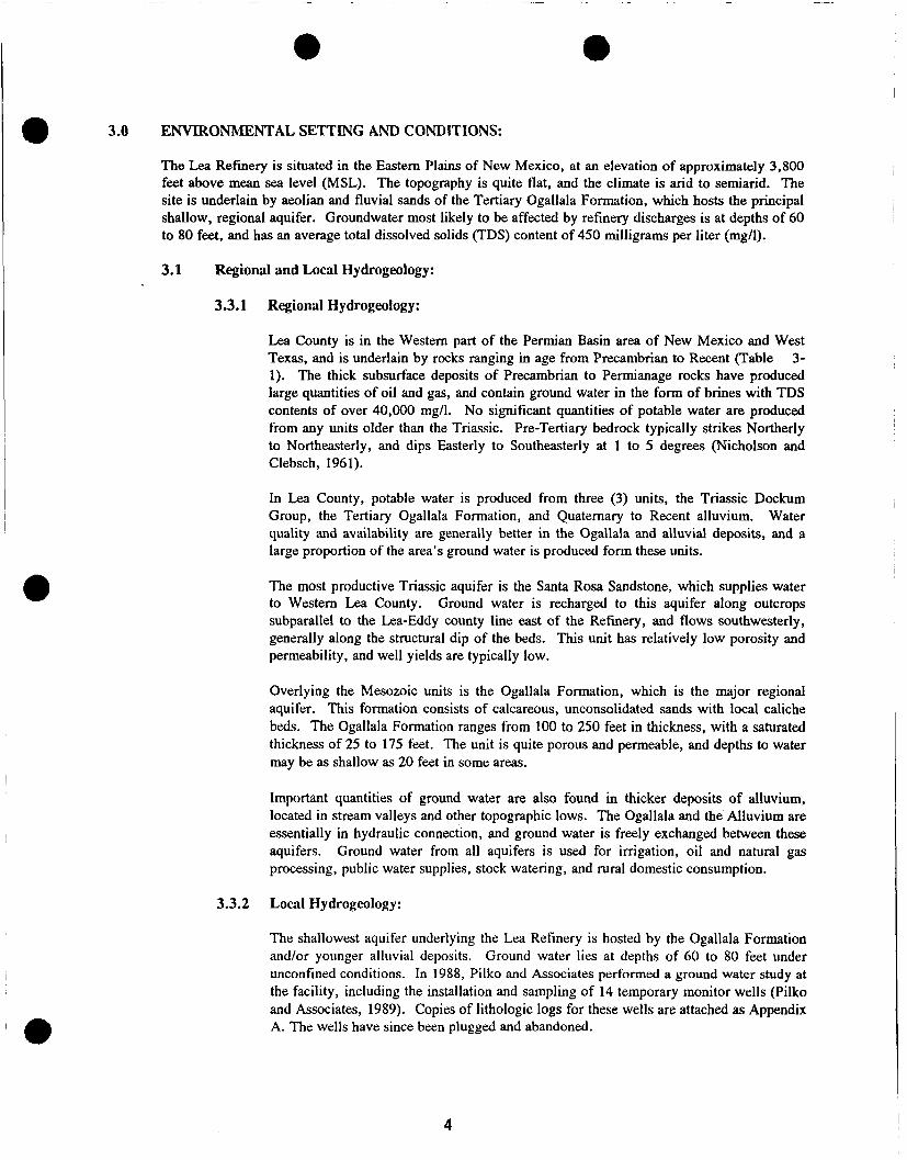
3.0 ENVIRONMENTAL SETTING AND CONDITIONS:
The Lea Refinery is situated in the Eastern Plains of New Mexico, at an elevation of approximately 3,800 feet above mean sea level (MSL). The topography is quite flat, and the climate is arid to semiarid. The site is underlain by aeolian and fluvial sands of the Tertiary Ogallala Formation, which hosts the principal shallow, regional aquifer. Groundwater most likely to be affected by refinery discharges is at depths of 60 to 80 feet, and has an average total dissolved solids (TDS) content of 450 milligrams per liter (mg/l).
3.1 Regional and Local Hydrogeology:
3.3.1 Regional Hydrogeology:
Lea County is in the Western part of the Permian Basin area of New Mexico and West Texas, and is underlain by rocks ranging in age from Precambrian to Recent (Table 3-1). The thick subsurface deposits of Precambrian to Permianage rocks have produced large quantities of oil and gas, and contain ground water in the form of brines with TDS contents of over 40,000 mg/l. No significant quantities of potable water are produced from any units older than the Triassic. Pre-Tertiary bedrock typically strikes Northerly to Northeasterly, and dips Easterly to Southeasterly at 1 to 5 degrees (Nicholson and Clebsch, 1961).
In Lea County, potable water is produced from three (3) units, the Triassic Dockum Group, the Tertiary Ogallala Formation, and Quaternary to Recent alluvium. Water quality and availability are generally better in the Ogallala and alluvial deposits, and a large proportion of the area's ground water is produced form these units.
The most productive Triassic aquifer is the Santa Rosa Sandstone, which supplies water to Western Lea County. Ground water is recharged to this aquifer along outcrops subparallel to the Lea-Eddy county line east of the Refinery, and flows southwesterly, generally along the structural dip of the beds. This unit has relatively low porosity and permeability, and well yields are typically low.
Overlying the Mesozoic units is the Ogallala Formation, which is the major regional aquifer. This fonnation consists of calcareous, unconsolidated sands with local caliche beds. The Ogallala Formation ranges from 100 to 250 feet in thickness, with a saturated thickness of 25 to 175 feet. The unit is quite porous and permeable, and depths to water may be as shallow as 20 feet in some areas.
Important quantities of ground water are also found in thicker deposits of alluvium, located in stream valleys and other topographic lows. The Ogallala and the Alluvium are essentially in hydraulic connection, and ground water is freely exchanged between these aquifers. Ground water from all aquifers is used for irrigation, oil and natural gas processing, public water supplies, stock watering, and rural domestic consumption.
3.3.2 Local Hydrogeology:
The shallowest aquifer underlying the Lea Refinery is hosted by the Ogallala Formation and/or younger alluvial deposits. Ground water lies at depths of 60 to 80 feet under unconfined conditions. In 1988, Pilko and Associates performed a ground water study at the facility, including the installation and sampling of 14 temporary monitor wells (Pilko and Associates, 1989). Copies of lithologic logs for these wells are attached as Appendix A. The wells have since been plugged and abandoned.
4

1 'a i JXe _>— i O L i a L i q i d p U i C u i u t a -LU o u u L u e i n
GEOLOGIC ACE GEOLOCIC UNIT THICKNESS
(ft)
GENERAL CHARACTER WATER-BEARING PROPERTIES
Sand 0-30-Recent
and
Pleistocene
Dune sand, unconsolidated stabilized to drifting, semiconsolidated at depth; fine- to medium-grained.
Above the zone of saturation, hence, does not yield water to wells. Aids recharge to underlying formations by permitting rapid infiltration of rainwater.
Alluvium 0-400±
Channel and lake deposits; alternating thickbedded calcareous silt, fine sand, and clay; thickest in San Simon Swale; less than 100 feet thick in most places.
Saturated and highly permeable in places in east end of Laguna Valley. Forms continuous aquifer with Ogallala formation. Wells usually yield less than 30 gpm. Locally above the water table.
z
2 * o O
J8
> c O -n
Z
z !*! > 73
s o 73 n w
Semiconsolidated fine-grained calcareous sand capped with thick layer of
Pliocene Ogallala 0-300± caliche: contains some clay, silt, and gravel.
Major water-bearing formation of the area. Unsaturated in many localities, such as north side of Grama Ridge, west side of Eunice Plain, Antelope Ridge area, and Rattlesnake Ridge. Greatest saturated thickness along east side of Eunice Plain, west of Monument Draw, where wells yield up to 30 gpm. Highest yields, up to 700 gpm, obtained from wells along south edge of Eunice Plain, east of j a l .
S 5
Small isolated and buried residual Undifferentiated 35± blocks of limestone, about 3 miles east
of Eunice.
Possibly small isolated bodies of water locallv.
s S s :=
3 O 60 S 5 O
a
Claystone, red and green; minor fine-Chinle grained sandstones and siltstones; un-
formation 0-1270^- derlies all of eastern part of southern Lea County area: thins westward: absent in extreme west.
Yields small quantities of water from sandstone beds. Yields are rarely over 10 gpm. Water has high sulfate content.
Sandstone, chiefly red but locally white, gray, or greenish-gray; fine- to coarse-
Santa Rosa grained; exposed in extreme west; sandstone 14O-30O± underlies Cenozoic rocks in western
part of area, and is present at depth in eastern part.
Yields small quantities of water over most of the area. Some wells are reported to yield as much as 100 gpm. Water has high sulfate content.
a o c z D
> M 73
r-> o O c z
Undiffer- Siltstone, red, shale, and sandstone: entiated 90-400+ present at depth under all of southern
Lea County.
No wells are known to be bottomed in the red beds. Probably can yield very small quantities of high-sulfate water.
"c .2 JB a 5 u t e n
1 H i
Thick basin deposits ranging in character from evaporites to coarse clas-
6300-17,000± tics; thinnest on the east side of the area over the Central basin platform, thickest toward the southwest.
No presently usable water supply available from these rocks. Source of highly mineralized oil-field waters.
Granite, granodioritic and other igneous and metamorphic rocks; complex structure.
Not hydrologically significant.
5

TABLE 3-2 SUPPLY WATER ANALYSES
PARAMETER CONCENTRATION (mg/l) STANDARD (mg/l)
Arsenic 0.01 0.1
3arium 0.3 1.0
Cadmium <0.001 0.01
Chromium 0.001 0.05
Cyanide <0.1 0.2
F l u o r i d e 1.0 1.6
Lead <0.001 0.05
Mercury <0.0004 0.002
N i t r a t e (NO3 as N) 3.5 10.0
Selenium <0.01 0.05
S i l v e r <0.01 0.05
Uranium <0.5 5.0
Radium-22 6 (pCi/1) <0.6 30 pCi/1
Radium-228 (pCi/1) 4.2 Combined
Chloride 79.0 250
Copper 0.002 1.0
Iron 0.02 1.0
Manganese 0.002 0.2
Phenols <0.001 0.005
Sulfate 74.5 600
T o t a l Dissolved S o l i d s 453.0 1000
Zinc <0.01 10
pH 7.1 6 t o 9
Aluminum <0.1 5.0
Boron 0.2 0.75
Cobalt <0.01 0.05
Molybdenum 0.001 1.0
Nickel <0.01 0.2
6

Based on the logs of these wells, subsurface materials above the water table consist of fine-grained sand with local seams of caliche and silt.
Measurements of water levels in these monitor wells indicate a southeasterly flow direction with a water-table gradient of 0.002 ft/ft (Figure 3-1). Analyses (September, 1981) of water from the refinery supply wells (Table 3-2) indicate that the water quality is within primary drinking-water standards, with a total dissolved solids content of 453 mg/l. The Lea Refinery and the City of Lovington draw their water from wells completed in this shallow aquifer.
Refinery water is drawn from two wells, located near the refinery office (Figure 3-1). The northern well is completed at a depth of 235 feet, and the southern well at 248 feet. Both wells were drilled to the top of a locally continuous clay strata, which is the base of the local shallow aquifer. The casings of both wells are perforated from 78 to 228 feet, and both pumps are set at 175 feet. At the time of the Pilko studies, the refinery wells had not been pumped for approximately 4 years, therefore the water table shown in Figure 3-1 shows no effects from these wells.
3.3.3 Local Wells and Water Usage:
All water wells registered with the New Mexico State Engineer's Office (NMSEO) that lie within 1 mile of the Refinery boundary are shown in Figure 3-2. Well locations shown on Figure 3-2 are taken from the legal descriptions in the well logs, and are at best accurate to the nearest quarter section. Where possible, well locations have been identified by their correspondence to well symbols on the topographic base map. Also, features identified as water wells or windmills on the topographic map have been identified, even if they were not listed in the NMSEO records. It is possible that additional unmapped or unregistered wells exist.
There are no perennial streams or permanent bodies of surface water within one mile of the facility. Surface water does accumulate in several intermittent lakes or playas to the northwest and east of the site. The southeasterly slope of the land's surface (see Figure 3-1) will prevent any potential release of wastewater or stormwater from reaching these areas.
3.4 SURFACE DRAINAGE AND FLOODING POTENTIAL:
Annual rainfall in the Lovington area averages 14 inches per year, most of which falls as late summer and autumn rains. The local topography is relatively flat, and slopes to the southeast at approximately 25 feet per mile (see Figure 3-1). There is no well-integrated, natural drainage system in the area; surface runoff is controlled by small arroyos and swales which drain to the southeast along the general topographic slope.
The refinery's tanks are bermed to contain any stormwater which falls within the area immediately surrounding the tank perimeters, and the same berms serve to prevent run-on of off-site stormwater. Process and loading areas are paved and bermed, and stormwater from these areas is diverted to the wastewater treatment system (see Section 4.4.3). Table 3-3 shows the estimated maximum rainfall events for 2, 5, 10, 25, 50 and 100-year storm events (United States Department of Agriculture, 1973). This table also includes a calculated total discharge per acre in gallons for each event.
7

STATE HIGHWAY 18
4 H TEXAS lc NEW MEXICO RAILROAD
TK-1201A
TW-7/
to
TK-12i 11B
CD
1X^1201 C TK=J201D
H f- H — { 1 f-
TK-1000F
O TK-1000C
oo JK-1000E
• ® TW-3 X X
<§) SAMPLE LOCATION & TEMPORARY WELL LOCATION
® TEMPORARY WELL LOCATION FINAL STUDY - SOUTHERN UNION
© TEMPORARY WELL LOCATION FINAL STUDY - HOLLY CORPORATION I | Figure 3-1 .
O PLANT WATER WELLS j SOUTHERN UNION REFINERY •33 WATER LEVEL ELEVATION (RELATIVE TO AN ASSUMED ELEVATION, JANUARY 1989) W A T E R L E V E L C O N T O U R M A P
DIRECTION OF GROUNDWATER FLOW ; PILKO * ASSOCIATES, INC.
0
L

TABLE 3-3 24-HOUR PRECIPITATION EVENTS
EVENT FREQUENCY (YEARS) PRECIPITATION (INCHES) GALLONS PER ACRE
2 2.6 70,800
5 3.4 92,500
10 4.0 109,000
25 4.8 131,000
50 5.0 136,000
100 6.0 163,000
9

I ... «N 1000
SCALE 1:24 000 o
2000 300O 4000 WOO f/xxj /ono r t n
1 Kll OMi rt H
n s ; MILS CONTOUR INTERVAL 5 FEET NATIONAL GEOOETIC VERTICAL DATUM OF 1929
Figure 3-2. WATER WELLS IN ONE-MILE RADIUS OF LEA REFINERY
10

4.0 PROCESS DESCRIPTION AND WASTEWATER GENERATION:
4.1 WATER SUPPLY AND TREATMENT:
The Lea Refinery uses approximately 111,500,000 gallons of water per year (gpy). Approximately 42% of this water (47,000,000 gpy) is lost to evaporation, and the remaining 58% is disposed of in the City of Lovington POTW. Figure 4-1 is a flow diagram which illustrates the water flow and water balance at the refinery. Plate 1 shows the locations of the major features of the water-supply and wastewater management systems.
4.1.1 Water Supply:
Water is supplied by 2 wells completed in the local Ogallala Aquifer. Together, these wells extract approximately 212 gallons per minute (gpm) on a yearly average. Water chemistry is shown in Table 3-2. Water is held in Tank 1210 (Plate 1) prior to distribution to sanitary, fire protection, water treatment and cooling systems. Water for steam generation and Merox processing is processed through a demineralizer; all other processes use untreated water.
4.1.2 Water Treatment:
Prior to use in the boilers and Merox process, water is treated in a full demineralization process. The water first passes through a cation zeolite catalyst where all cations are exchanged for hydrogen ions ( H + ) . The water then passes through a decarbonator stripper where C0 2 is stripped from the water prior to entering the anion catalyst part of the process. In the anion section all remaining anions (Ci" & S04~, etc.) are exchanged for hydronium ions (OH"). The hydrogen ions ( H + ) and the hydronium ions (OH") combine to make water (H 20). The cation zeolite catalyst is regenerated with hydrochloric acid (HCI) and the anion zeolite catalyst is regenerated with sodium hydroxide (NaOH). The waste from regeneration of the zeolite catalyst goes directly to sewer. The waste acid from the cation units and the waste caustic from the anion units will neutralize each other in Tank 1201D. These regenerate waste streams do not pass through the refinery oil-water separator (Corrugated Plate Separator #1) since they contain no oil and potentially could affect the efficiency of the separator due to differences in pH. Based on the manufacturer's specifications and projected demineralized water demand, the waste water generated should average about 8 gpm, although the waste is actually generated only when zeolite units are regenerated.
Refining processes require heating and cooling of process units to achieve optimum operating temperatures. Temperature control is achieved by circulation of steam or cooling water, as appropriate to the process. Steam is also used as an energy source for vacuum jets, to operate turbine pump, and for wastewater stripping. Steam production and cooling systems generate wastewater in the form of blowdown water (as described below), which is rejected to maintain the correct TDS in the boilers and cooling towers.
4.2.1 Cooling Towers:
The refinery cooling needs are met by a 10,000 gpm recirculating cooling tower, which draws approximately 130 gpm of water during average operation, of this 130 gpm, 90 gpm is lost to evaporation and 40 gpm is rejected as blowdown. Chemical additives employed to prevent fouling and corrosion are listed in Table 4-1, and Material Safety Data Sheets are included as Appendix B. None of these chemicals or their ingredients are
4.2 COOLING AND STEAM GENERATION PROCESSES:
11
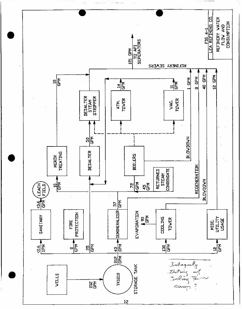
3: u_
•-« OJ
CO
oc H D Q - r -< <
QC a u r - 0 _
oo
i
u.
ri 01 u T
r Z
a < a 2 h-4
> z •—4 I—
Z o_ I—I >- 3 : U. DC > ZD U Ul • (A
z _ i Z M Lu •
< u
U. Ul oc
SH3A3S Aa3NIJ3d
a: UJ
r - > < T
O
fx a. 13 ^
a. 13
ti oc
ti Ul <r > > 0 >
r -
a. 13
00
z a 1—1 r -<r or ui z UJ 13 U l Ql
a. 13
o
z > a • _ i m
• •—I i -<r oc • a. < > ui
0-13
(VI
13 01 Z Ul 1—1 _J > a • • 0
0 2 : 0 a. «-4 0
>-U l U l
0 1—1 13 </> _J <T. Y—t 2 :
UTI
US
OJ 2 : a. a
12

listed as carcinogenic under OSHA Standards (40 CFR 1910.1200). This table also includes a calculation of the loading of these chemicals in the blowdown waste stream. These additives increase the wastewater TDS by approximately 46 ppm.
Prior to the 1984 shutdown, chromium compounds were used as corrosion and biological control agents in the cooling towers. Soils in the vicinity of the cooling towers that exhibited elevated chromium levels have been excavated and removed to a permitted disposal facility. No chromium compounds will be used
TABLE 4-1 COOLING TOWER AND BOILER ADDITIVES
COOLING TOWERS
ADDITIVE USAGE IN GAL/YEAR FUNCTION
Unichem 1300 2200 Scale Control
Unichem 512 520 Biocide
Unichem 570 520 Biocide
Chlorine Tablets 175 Bacteria Control
TOTAL GALLONS/YEAR 3415
TDS LOADING* (ppm) 46
BOILERS AND WATER TREATMENT
ADDITIVE USAGE GAL/YEAR FUNCTION
Unichem 3030 2550 Corrosion Control
Unichem 3140 1800 Oxygen Scavenger
Unichem 3235 1800 Neutralizing Amine
Unichem 3510 730 Corrosion Control
Unichem 3310 185 Corrosion Control
Unichem 4500 96 Zeolite Cleaner
TOTAL GALLONS/YEAR 7161 -
TDS LOADING* (ppm) 97
* TDS Loading based on 74,000,000 gallons/year of wastewater discharge.
13

4.2.2 Steam Generation:
Steam is expected to be produced at a rated capacity of 36,000 pounds per hour (lb/hr), using both fired boilers and waste-heat recovery. The steam is used for general process heating, fractionation stripping and vacuum-jet motive steam. Steam generation consumes an annual average of 25 gpm of treated water, along with an estimated 45 gpm of returned steam condensate. Only steam from non-contact process heating is condensed and recycled into the boiler makeup water. Contact steam, from the stripping and vacuum-jet processes, may contain hydrocarbons and is therefor routed to the desalter prior to stripping for benzene removal and discharge to the oily sewer system. Since such high purity water is used to make steam only a very small amount of boiler blowdown will occur. This is estimated to be only 1 gpm or perhaps less.
A number of chemicals are used to prevent scaling and corrosion, and to maintain boiler water at an optimal pH of 11.0. These are listed in Table 4-1, and Material Safety Data Sheets are included as Appendix B. None of these chemicals or their ingredients are listed as carcinogenic under OSHA Standards (40 CFR 1910.1200).
Boiler blowdown water has traces of TDS, as well as traces of additive chemicals. Table 4-1 also includes a calculation of the approximate loading of these chemicals in the final waste stream. In total, boiler additives increase the TDS of the wastewater by approximately 100 ppm by volume.
4.3 PETROLEUM REFINING PROCESSES:
Treated water from the demineralizer is used for Merox treating; most other refining processes that consume water use it in the form of steam except desalting, which uses a combination of raw water makeup and condensed contact waters. All process wastewaters are routed to the wastewater treatment system prior to discharge to the Lovington POTW.
4.3.1 Desalting:
Crude oil feedstocks contain sodium, magnesium and calcium salts, primarily as chlorides, as well as minor amounts of suspended solids. In the desalting process, water is mixed with the crude oil to dissolve these salts and to scavenge the suspended solids. The water is removed by settling in the presence of an electric field. Conditioning chemicals and their levels of usage are listed in Table 4-2.
This process consumes approximately 50 gpm of water, and produces an equal quantity of wastewater. This wastewater has elevated TDS in the form of salts, spent treatment chemicals (approximately 175 ppm) and small amounts of dissolved and suspended hydrocarbons.
14

TABLE 4-2 DESALTER AND MEROX ADDITIVES
DESALTER
ADDITIVE USAGE GALLONS/YEAR FUNCTION
P e t r o l i t e 7140 3650 Demulsifier
P e t r o l i t e 7210 730 Wetting Agent
P e t r o l i t e 4030 9125 Antifo u l a n t
P e t r o l i t e 1202 2190 Film Control
P e t r o l i t e 1100 912 Neutralizer
TOTAL GALLONS/YEAR 12,957
TDS LOADING* (ppm) 175
MEROX ADDITIVE
ADDITIVE USAGE FUNCTION
Sodium Hydroxide 128 tons/year REAGENT
UOP Merox FB 85 gal/year CATALYST
TDS LOADING* (ppm) 418 mg/l
* TDS loading based on 74,000,000 gallons/year of wastewater discharge
15

4.3.2 Merox Treating:
The Merox process uses a proprietary catalyst to convert mercaptans, which are corrosive and cause odor problems, into disulfides that can be returned to the products (naphtha and kerosene). Mercaptans are extracted with sodium hydroxide and then oxidized by air injection in the presence of the catalyst. Treated water is used to wash excess sodium hydroxide from the product stream, and the water is separated by settling.
This process consumes approximately 10 gpm of treated water. The wastewater contains rejected sodium hydroxide which increases the TDS and the pH, traces of spent catalytic reagent (see Table 4-2), and small amounts of dissolved and suspended hydrocarbons.
4.3.3 Atmospheric Fractionation, Stabilization and Vacuum Distillation:
These processes separate the various petroleum fractions from crude oil by distillation, either at atmospheric pressure or under vacuum. Steam is used for either direct (contact) or indirect (non-contact) heating, and for vacuum generation by jetting.
Wastewater is generated by condensation of steam in the presence of crude oil and products. The atmospheric tower produces approximately 14 gpm, and the vacuum jets approximately 11 gpm. These wastewaters have elevated TDS, and also contain dissolved and suspended hydrocarbons, but are of sufficient quality to serve as makeup to the desalter, thus reusing and conserving water in the process.
4.4 OTHER WASTEWATER STREAMS:
4.4.1 Sanitary Sewers:
The refinery sanitary sewers produce approximately 0.6 gpm of wastewater. This stream is not commingled with process wastewater, and is routed to onsite septic systems with buried leach fields. The sanitary system is separate from the process and loading area drains, and receives no non-sanitary discharges.
4.4.2 Fire Protection:
Fire protection water is taken from the main water holding tanks, prior to the treatment system. In normal operations this system neither consumes water nor generates wastewater. Relatively minor amounts of water may be discharged to grade during periodic system testing; this water will enter the wastewater treatment and disposal system in the paved process areas, or infiltrate and evaporate in the unpaved areas.
4.4.3 Storm Water:
Based on an average annual rainfall of 14 inches per year, runoff will average approximately 381,000 gallons per year, or 1044 gpd (0.73 gpm) for the paved process areas and 285,750 gallons per year (0.54 gpm) from the loading-rack area. Combined, this represents only 1 % of total wastewater production.
The paved process and loading-rack areas are drained by separate storm-sewer networks that are connected to the wastewater treatment and disposal system (Plate 1). Stormwater from these, areas may contain hydrocarbons, and will not be allowed to discharge to grade. Primary storm surge capacity is provided by the bermed, paved areas, and discharge to the separators will be regulated by several mechanisms to prevent releases.
16

The 100-year storm event (6 inches in 24 hours) will produce a total of approximately 300,000 gallons of runoff from the process and loading areas, or about 1.5 times the normal daily discharge. Surge-control capacity for the process areas is provided by the bermed, paved areas and by pumpage to the first of two (2) 3.3 million-gallon holding tanks, adequate to contain approximately 20 times the 100-year maximum daily precipitation. In the loading-rack area, the paved areas will retain the storm surge until it can be safely pumped to the treatment system. In both the process and loading-rack areas, the stormwater that will accumulate in the paved areas can be safely drained and treated in a matter of hours.
PROCESS AREAS:
Paved process areas have an area of approximately 1 acre. For individual storm events, each inch of rainfall will produce approximately 27,225 gallons of runoff per acre (assuming 100% runoff). The storm sewers are designed for a rainfall rate of 1.5 inches per hour, or 40,838 gallons per hour (680 gpm). Because this flow will exceed the capacity of the oil-water separator, a steam-powered pump operated by a high-low level switch has been installed in the collection sump that feeds the separator (see Section 5.2). This pump has a capacity of 1000 gpm, and the excess wastewater will be passed through a 6" inch line to the 3.3-million-gallon holding tank (Tank 1201 D; Plate 1). If rainfall exceeds the 1.5-inch-per-hour capacity of the sewer system, it will accumulate and be held in the paved areas until it drains.
If process units produce 121 gpm, and the storm sewers contribute 680 gpm, the total flow to the sump will be 801 gpm. The emergency removal capacity will be the sum of the normal separator capacity of 300 gpm, plus the pump capacity of 1000 gpm, for a total of 1300 gpm. Thus the system has a safety factor of 499 gpm, or 162%.
The estimated 100-year storm event for the Lovington area is 6 inches in a 24hour period. This would produce approximately 163,350 gallons of water in the 1-acre process area. Berms around the process areas will contain the water for the 4 hours required for the sewer system to drain this amount of water.
LOADING RACK AREA:
A paved area of approximately 0.75 acres, located south of the refinery, is used as a truck-loading rack. This area is also equipped with a storm-sewer system, a sump and a pump to transfer any collected water or spillage to the refinery oil-water separator system.
The loading area will produce approximately 20,400 gallons of runoff per inch of rainfall, and the sewer system also has a capacity of 1.5 inches of rain per hour, or 30,628 gallons per hour (510 gpm). As is the case in the process area, the average depth of retained water in a 100-year storm event will be 6 inches. This represents a volume of 122, 500 gallons. The paved and bermed area will be drained at a rate which will not exceed the capacity of the sump and transfer pump.
TANK-BERM AREA:
Areas surrounding the crude oil and product storage tanks are surrounded by berms which are designed to retain the tank volume plus a safety factor of one third; these berms also prevent inflow or runoff of stormwater. Direct precipitation will accumulate inside the berms, where it will normally be dispersed by evaporation and infiltration. If floating hydrocarbons are noted on stormwater inside tank berms, the oily water will be removed by vacuum truck and transported to the separator.
17
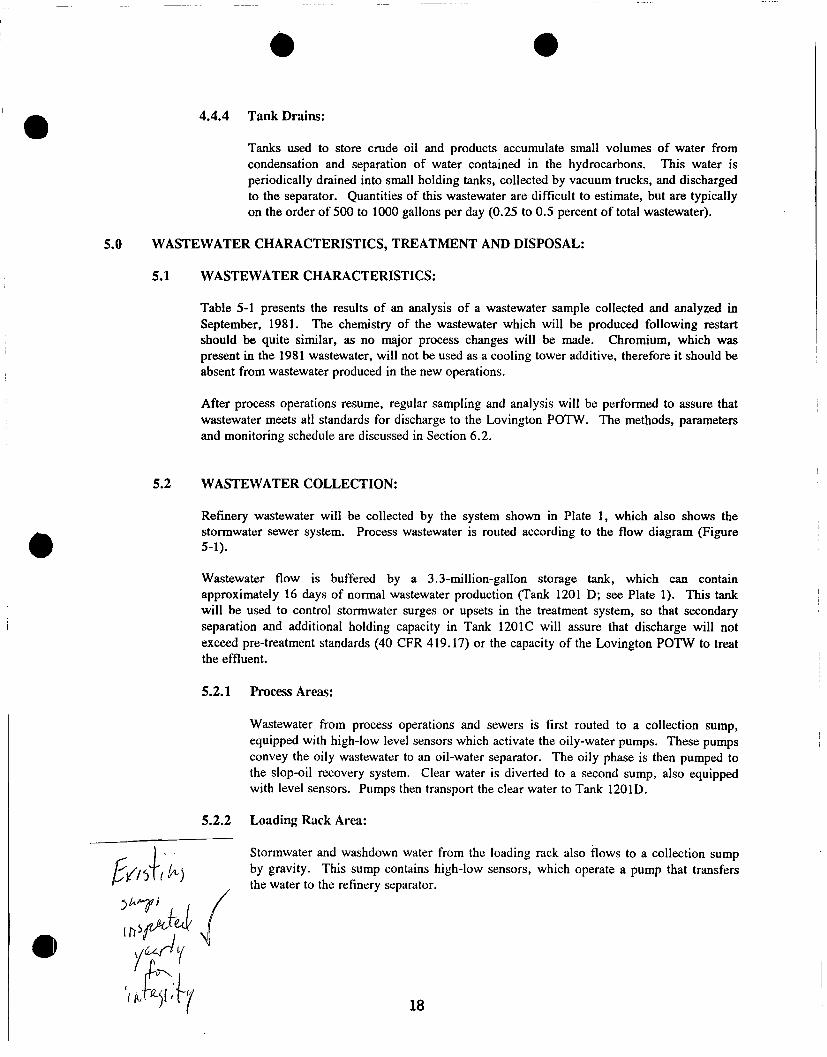
4.4.4 Tank Drains:
Tanks used to store crude oil and products accumulate small volumes of water from condensation and separation of water contained in the hydrocarbons. This water is periodically drained into small holding tanks, collected by vacuum trucks, and discharged to the separator. Quantities of this wastewater are difficult to estimate, but are typically on the order of 500 to 1000 gallons per day (0.25 to 0.5 percent of total wastewater).
5.0 WASTEWATER CHARACTERISTICS, TREATMENT AND DISPOSAL:
5.1 WASTEWATER CHARACTERISTICS:
Table 5-1 presents the results of an analysis of a wastewater sample collected and analyzed in September, 1981. The chemistry of the wastewater which will be produced following restart should be quite similar, as no major process changes will be made. Chromium, which was present in the 1981 wastewater, will not be used as a cooling tower additive, therefore it should be absent from wastewater produced in the new operations.
After process operations resume, regular sampling and analysis will be performed to assure that wastewater meets all standards for discharge to the Lovington POTW. The methods, parameters and monitoring schedule are discussed in Section 6.2.
5.2 WASTEWATER COLLECTION:
Refinery wastewater will be collected by the system shown in Plate 1, which also shows the stormwater sewer system. Process wastewater is routed according to the flow diagram (Figure 5-1).
Wastewater flow is buffered by a 3.3-million-gallon storage tank, which can contain approximately 16 days of normal wastewater production (Tank 1201 D; see Plate 1). This tank will be used to control stormwater surges or upsets in the treatment system, so that secondary separation and additional holding capacity in Tank 1201C will assure that discharge will not exceed pre-treatment standards (40 CFR 419.17) or the capacity of the Lovington POTW to treat the effluent.
Process Areas:
Wastewater from process operations and sewers is first routed to a collection sump, equipped with high-low level sensors which activate the oily-water pumps. These pumps convey the oily wastewater to an oil-water separator. The oily phase is then pumped to the slop-oil recovery system. Clear water is diverted to a second sump, also equipped with level sensors. Pumps then transport the clear water to Tank 1201D.
Loading Rack Area:
Stormwater and washdown water from the loading rack also flows to a collection sump by gravity. This sump contains high-low sensors, which operate a pump that transfers the water to the refinery separator.
5.2.1
5.2.2

TABLE 5-1 WASTEWATER CHEMISTRY
PARAMETER CONCENTRATION (mg/l) STANDARD (mg/l)
Arsenic 0.1 0.1
Barium 0.5 1.0
Cadmium <0.001 0.01
Chromium 0.053 0.05
Cvanide 0.26 0.2
F l u o r i d e 1.7 1.6
Lead 0.005 0.05
Mercury <0.0009 0.002
N i t r a t e (N03 as N) 0.8 10.0
Selenium <0.01 0.05
S i l v e r <0.01 0.05
Uranium 14.0 5.0
Radium-226 (pCi/1) <0.6 30 pCi/1
Radium-228 (pCi/1) 3.1 Combined
C h l o r i d e 505 250
Copper 0.005 1.0
I r o n 4.6 1.0
Manganese 0.002 0.2
Phenols 0.327 0.005
S u l f a t e 292 600
T o t a l Dissolved S o l i d s 1300 1000
Zinc 0.1 10
PH 9.8 6 t o 9
Aluminum <0.1 5.0
Boron 2.0 0.75
Cobalt <0.01 0.05
Molybdenum <0.001 1.0
N i c k e l <0.01 0.2
Benzene 1.0 0.01
Ethylbenzene <1.0 0.75
19

5.3 WASTEWATER TREATMENT:
All oily wastewater from the refinery and the loading rack discharge to a sump ahead of Corrugated Plate Separator #1 (CPS) as shown on Figure 5-1. There are two sets of pumps located at this sump and under normal flow conditions one set of pumps (main and spare) lifts the oily water into the CPS.
A corrugated plate separator consists of a pack of parallel corrugated plates that act to separate oil, water and sediment in the feed water. The separated oil is skimmed off the unit and pumped to slop oil storage from which it will be reprocessed in he refinery. The sediment, in the form of an oily sludge, settles in a sump at the bottom of the unit where it is pumped into an elevated above ground storage tank. The accumulated sludge will be properly manifested offsite for hazardous waste incineration. The clear water exits the separator into a sump where the demineralizer regeneration waste combines with it. The clear water is then pumped to tank 1201D.
In the event of a power failure, the pumps that charge the separator will not operate. As the level in the oily water sump rises a steam driven pump will come on and begin transferring the wastewater directly to Tank 1201D. Due to the infrequent occurrence of powerfailures and the large capacity (is long holding time) of Tank 1201D, the occasional transfer of unseparated wastewater should not effect the quality of the final discharge. The steam turbine pump also serves as a large capacity pump needed during storm events. The corrugated plate separator can only process 300 ppm, therefore storm flows in excess of 300 gpm will be transferred directly to Tank 1201D by the turbine pump.
Water in Tank 1201D will gravity feed into a second corrugated plate separator (CPS #2) where any remaining oil and sludge will be drawn off to their respective storage and handling systems. After this secondary separator step, the water will be lifted into Tank 1201C, where it will be held until rateably pumped the 3.7 miles to Lovington. The City of Lovington has a sewer main on the South end of town that will receive the refinery effluent and transfer it to the treatment works.
5.4 WASTEWATER DISPOSAL:
Treated wastewater from the refinery will be pumped approximately 20,000 ft. through a HDPE pipeline that ties into the City of Lovington sanitary sewer system. This pipeline will be equipped with a pig launcher and catcher system so that the capacity of the line can be maintained in the unexpected event of any settling or precipitation restricting the flow. It is not anticipated that the
/' / line will be pigged more than just a few times a year.
j Once the refinery effluent enters the Lovington sewer system it will be commingled with the city " f u -t^S t*r&~' sanitary wastewater and processed through the city POTW. All treated effluent from the city is / f / T y stored and used for irrigation of a 640 acre farm which borders the treatment plant. Navajo
r ' J J l A 1 \ contracted the consulting firm of Parkhill, Smith and Cooper (PSC) in El Paso, Texas to evaluate f J^t->J the addition of the refinery effluent to the city POTW. Their study indicates that no detrimental
<?r cuJL i^JJfZX'-j effects on treatment or final disposal will occur due to the refinery effluent. PSC is preparing a permit modification for submittal by the City of Lovington to NMEID Groundwater Bureau supporting these findings.
Discharge of the refinery effluent to the City of Lovington will be directly regulated by EPA Region VI in Dallas, Texas under the Federal Pre-treatment Regulations (40 CFR 403 and 40 CFR 419.17). These pre-treatment regulations require, among other things, that Navajo meet maximum discharge standards of 100 ppm oil and grease, 100 ppm ammonia and 1 ppm total chromium. The pre-treatment regulations require Navajo to sample and analyze the effluent twice a year to demonstrate compliance.
20


5.5 OTHER WASTES:
The Refinery will also generate solid wastes and potentially hazardous wastes. Solid wastes (domestic and industrial trash) are collected in dumpsters and transported to a landfill by a local contractor.
Wastes which are hazardous will be collected at their points of generation, properly containerized manifested, and transported to a licensed treatment, storage and disposal facility in accordance with the regulations of the Resource Conservation and Recovery Act (RCRA) . At no time will the Refinery facility be used for the treatment, storage or disposal of hazardous wastes.
Hazardous wastes will include separator sludges, sludge from cleaning heat exchangers, slop oil emulsion solids and possibly waste or off-specification chemicals. All of these wastes will be managed under RCRA regulations, in accordance with the rules applicable to generators of those wastes (40 CFR 260-262).
MONITORING, REPORTING AND OTHER REQUIREMENTS:
6.1 GROUND WATER AND VADOSE-ZONE MONITORING:
Because no wastewater will be disposed of on site, no ground water or vadose zone monitoring is proposed.
6.2 EFFLUENT MONITORING:
Effluent monitoring and reporting requirements under EPA's Pre-treatment Program are found in 40 CFR 403.12. Section 403.12.b.4 requires flow measurement that will show average daily and maximum daily flow in gallons per day discharged to the POTW. Navajo will install a flow recorder on the pipeline to Lovington to comply with this requirement.
Protocols for sample collection and analysis are given in Section 403.12.b.5 and require that 24 hour composite samples be collected for analysis. Table 6-1 identifies the sampling schedule and analytical methods. In addition to the categorical standards given in 40 CFR 419.17 for oil and grease, ammonia and chromium, Navajo will be analyzing wastewater samples for pH, sulfide and BTEX. Reporting requirements under Section 403.12.e require the above analyses to be done twice a year for reporting in June and December of each year. Additionally Navajo must analyze and report to EPA within 90 days of startup to demonstrate initial compliance.
6.3 LEAK DETECTION, SPILL PREVENTION AND CONTINGENCY PLANS:
Prior to the restart of the refinery, all process and wastewater tanks, lines and appurtenances will be inspected and tested according to manufacturer's and industry standards. Repair will be performed as necessary to assure safe and efficient operation before processing begins.
The refinery will operate on a 24-hour schedule, and will be under the continuous observation and supervision of experienced staff. Any significant problems with the wastewater system will be immediately reported to the plant operator, who will issue a work order for prompt repair.
6.3.1 Wastewater Systems:
A key part of release prevention are the two (2) 3.3 million gallon holding tanks (1201C and 1201 D; Plate 1). These tanks can hold up to 37 days of wastewater production, or
22

40 times the 100-year storm runoff for the process areas. Secondary containment for effluents will be provided by the paved process areas, which are bermed to prevent inflow from adjacent areas, as well as to prevent release of wastewater to grade.
Before reaching the collection sumps, wastewater will flow by gravity through the refinery sewer system. All sewer lines will be cleaned and inspected prior to process startup. If blockage or flow problems are noted during operation, vacuum trucks or portable pumps will be used to convey wastewater to the treatment system until repairs can be made.
Pumps and pressurized lines will convey untreated wastewater, recovered slop oil and treated wastewater through the rest of the collection and treatment system. These lines will be inspected and tested prior to use.
6.3.2 Process, Loading and Tank Areas:
Any spill or other release in the process areas or loading racks will be controlled and retained by the pavement and berms. Lost materials will be recovered by the separators and returned to the appropriate part of the
TABLE 6-1 WASTEWATER SAMPLING SCHEDULE AND MEHTODS
PARAMETER SAMPLING INTERVAL EPA METHOD
Oil & Grease 1 Every 6 Months 413.1
Ammonia 1 Every 6 Months 350.1, 350.2 or 350.3
Chromium 1 Every 6 Months 218.1 or 218.2
PH 1 Every 6 Months 9040
Sulfide 1 Every 6 Months 376.1 or 376.2 BTEX 1 Every 6 Months 602 or 8020
23

Treatment and process chemicals (see Section 4.0) will be stored in approved containers in the paved process areas. Regular inspection of these containers will detect any releases. If a release is noted, it will be cleaned up in accordance with safety and environmental concerns identified in the manufacturer's MSDS data (Appendix B).
Cleanup wastes will be recycled or disposed of in accordance with manufacturer's instructions and/or applicable regulations.
Potential spills of products or feedstocks outside the paved areas will be controlled by industry-standard practices. In general, these releases will be controlled by temporary earth berms or other emergency structures until the materials are recovered by vacuum truck or other methods. Any impacted soils or other materials will be removed to the extent practical. Analyses (by methods described in SW-846 for the appropriate parameters) to determine their contents and regulatory status will be done and then the waste will be properly disposed of.
In the event of fire or explosion, quantities of fire-fighting water and other chemicals may be used. In the paved areas, these will be collected by the sewers and transported to the normal wastewater treatment system. In the tank areas, these wastewaters will be retained by the tank berms, removed by vacuum truck or temporary pumps, and discharged to the wastewater system.
6.4 REPORTING AND RECORD KEEPING:
All records pertaining to wastewater analyses and volumes, and any other aspects of Discharge Plan compliance, will be maintained at the Lea Refinery office for a period of 5 years.
Results of monitoring activities (wastewater volumes and analyses) will be reported to the NMOCD on a semiannual basis.
7.0 REFERENCES CITED:
G. A.. Baca and Associates, Ltd., 1981, Southern Union Refining Company Lovington Refinery Waste Water Discharge Plan; G. A.. Baca and Associates, Ltd., 36 p. with Plate.
New Mexico Water Quality Control Commission Regulations (as Amended Through November 25, 1988); New Mexico Water Quality Control Commission, Santa Fe, New Mexico, 91 p.
Nicholson, A. and Clebsch, A., 1961, Geology and Ground-Water Conditions in Southern Lea County, New Mexico; New Mexico Bureau of Mines and Mineral Resources Ground Water Report 6, 123 p.
Pilko and Associates, Inc., 1989, Groundwater Monitoring Well Installation, Sampling, and Analysis of Lovington, New Mexico Refinery (Prepared for Holly Corporation); Pilko and Associates, Inc., Houston, Texas, 8 p. with Appendices.
U.S. Department of Agriculture Soil Conservation Service, 1973, Peak Rates of Discharge for Small Watersheds; Engineering Manual for Conservation Practices, Chapter 2, U.S. Department of Agriculture, Washington, D.C, 32 p.
U.S. Code of Federal Regulations, Section 40 (Protection of the Environment), as revised 1990; U.S. Environmental Protection Agency, Washington, D.C.
U.S. Environmental Protection Agency, 1986-1991, Test Methods for Evaluating Solid Waste (SW-846), Third Edition, U.S. Environmental Protection Agency. Washington, D.C.
24

APPENDIX A

r ^.QG & AS-BUILT DIGRAM
GEOLOGIST: Darryi Carteon .
DRILLER: Southwest Engineering
DRILLING METHOD: Hollovretem Auger
COMPLETION DATE: 11-9-88
TOP OF CASING ELEV.: 114.4'
GROUND SURFACE ELEV.: 98.6'
GEOLOGIC LOG
•GROUND SURFACE • Borehole previously sampled 0'—15'
Dense, tan, fine SAND (Sa) —slight chemical odor
• —slight chemical odor
—with thin cemented seam at 30', and slight odor
—with thin cemented seam at 35'—36', chemical odor slightly stronger at 32'-35'
—questionable odor at 40'
-no detectable odor at 45'
-no detectable odor at 50*
-no detectable odor at 55' -weakiy cemented 58'-60'
no detectable odor at 60' -weakiy cemented seams at 61',
63', 65', no detectable odor at 65'
—with numerous cemented seams 65'-70\ no detectable odor at 70'
—with fewer cemented seams moist with no detectable odor at 75'
-no detectable odor at 80' saturated below 81'
-no detectable odor at 85'
o o LOG
DEPTH IN
FEET
Total Depth =* 90 ft
— 10-
"—ZQ-i
r-30-^
—40-
—50—
•70—
—80—
•90-=
AS BUILT 8"
PVC Siip-on
Cap ^F~j
Natural Soil Backfill
2-in. LD. Schedule 40 PVC Casing
Bentonite Powder
Bentonite Pellet Seal
r-
Sand Rlter
0.010* Slotted Screen
2-In. I.D. PVC Plug
15.0 ft
73.0 ft 75.0 ft 77.2 ft
87.2 ft 90.0 ft
PHXO ck ASSOCIATES, INC. TW-1
Southern Union Refinery Overflow Pond
Job No. 293 Nov., 1988 Page 1 of 1

r #PG & AS-BUILT DIGRAM
GEOLOGIST: Darryi Carlson
DRILLER: Southwest Engineering
DRILLING METHOD: Hollowstem Auger
COMPLETION DATE: 11—10—88
TOP OF CASING ELEV.: 100.0'
GROUND SURFACE ELEV.: 84.7'
GEOLOGIC LOG
•GROUND SURFACE Borehole previously sampled 0'—15'
Dense, tan, fine SAND (Sa) —damp, fuel odor (kerosene?)
15-20' • '-fuel odor 20-25'
-fuel odor 25-30' -light gray, slightly sflty and
weakly cemented 28'-34' -slight fuel odor 30-32' —no detectable odor 32'—35' —tan below 35' —no detectable odor 35'-40' —no detectable odor 40'—45' —light gray and weakly cemented
44-46' —no detectable odor 45'-50' ' —no detectable odor 50'—55' —weakly cemented 58'-60' -no detectable odor 55'-60' —weakly cemented 63'—65' —no detectable odor 60'-65* —moist below 65' -no detectable odor 65'-70' -wet at 70'
-no detectable odor 70'-75'
i -o o
m
Total Depth = 80 ft
LOG DEPTH
IN FEET
— 10 —
r-20-^
— 3 0 —
— 4 0 —
— 5 0 —
r-60-^
— 7 0 —
— 80—
7-90-:
AS BUILT 8*
PVC Slip-on Cap
Natural Soil Backfill
2-tn. LD. Schedule 40 PVC Casing
Bentonite Powder
Bentonite Pellet Seal
Sand Rlter
0.010" Slotted Screen
2-in. I.D. PVC Plug
PILKO ie ASSOCIATES, INC. TW-2
Southern Union Refinery AP! Truck Rack
10.0 f t
61.5 ft 63.5 ft
69.5 ft
79.5 ft
Job No. 293 Nov., 1988 Page 1 of 1

#LQG & AS-BUILT D#GRAM
GEOLOGIST: Darryi Carison
DRJLLER: Southwest Engineering
DRILLING METHOD: Hollowstem Auger
COMPLETION DATE: 1—20—89
TOP OF CASING ELEV.: 115.85*
GROUND SURFACE ELEV.: Not Determined
GEOLOGIC LOG
-GROUND SURFACE Hard, tan and light gray cemented
sand Dense, tan fine sand
—with thin cemented seams 16 to 18 ft . . . - :
—with occasional weakly cemented seam3 20 to 25 ft
—weakly cemented 30 to 40 ft
—with occasional thin cemented seams 58 to 60 ft
-with occasional thin cemented seams 55 to 72 ft
-saturated below 80 ft
-no odor or stain 0 to 89 ft
Total Depth =« 89 ft
t -o o LOG
DEPTH IN
FEET
—10 —
r-20-E
-30—
—40-
• *
—50-
=-60—
• -
•70—
•80—
r-90—
AS BUILT 8'
PVC Slip-on Cap
Bentonite Powder
2-in. I.D. Schedule 40 PVC Casing
Natural Soil Back-fUl
A/1
Bentonite Pellet Seal
Sand Rter
0.010* Slotted Screenf.
~2=fnrtrr PVC Plug
fi
20.0 ft
61.0 ft 63.0 ft
75.0 ft
85.0 ft
89.0 ft
PILKO it ASSOCIATES, INC. TW-3
Southern Union Refinery New Mexico
Job No.: 7599 Jan., 1989 Page 1 of 1

#LQG & AS-BUILT DIGRAM
GEOLOGIST: Darryi Carlson
DRILLER: Southwest Engineering
DRILLING METHOD: Hollowstem Auger
COMPLETION DATE: 1-21—89
TOP OF CASING ELEV.: 109.76'
GROUND SURFACE ELEV.: Not Determined
GEOLOGIC LOG
-GROUND SURFACE Hard, tan and light gray cemented^
3and Dense, tan and light gray calcareous
sand
Dense, red-and brown silty fine 3and
Dense, tan fine sand
—no odor or stain 0 to 85 f t
Total Depth =« 85 ft
O O LOG
DEPTH IN
FEET
LU
— 10 —
—20—.
• •«
—30—
—40—
• -
—50—
—60—
—70-
—80—
r-90-^
AS BUILT 8"
PVC Siip-on Cap
Bentonite Powder
2-in. LD. Schedule 40 PVC Casing
Natural Soil Backfill
Bentonite Pdlet Seal
Sand Filter
0.010" Slotted Screen
5
2-in. I.D. PVC Plug
20.0 ft
61.0 ft 63.0 ft
74.0 ft
85.0 ft
PILKO <k ASSOCIATES, INC. TW-4
Southern Union Refinery New Mexico
Job No.: 7599 Jan., 1989 Pcge 1 of 1

I o
r 3
j
il
1
1 a
•.OG & AS-BUILT DlffcRAM GEOLOGIST: John Buchanan
DRILLER: Southwest Engineering
DRILLING METHOD: Hollowstem Auger
COMPLETION DATE: 1—16—89
TOP OF CASING ELEV.: 9&73'
GROUND SURFACE n FV - Not Determined
GEOLOGIC LOG
•GROUND SURFACE
LU o o LOG
DEPTH IN
FEET
Dense, tan silty sand
Hard, tan and light gray cemented^ sand
Dense, tan silty 3and Hard, tan and light gray cemented/
sand Dense, tan fine sand
: — t a n and white below 20 ft
—reddish brown below 34 ft
—tan below 60 ft
—no odor or stain 0 to 74.5 ft
Total Depth = 74.5 ft
•10 —
• *
7-20-f.
•30—
• •*
—40-
—50—
'—60-
—70-
—80-
—90—
AS BUILT 8**
PVC Slip-on Cap
Bentonite Powder .
2-In. LD. Schedule 40 PVC Casing
Natural Soli Backfill
Bentonite Pellet Seal
Sand Filter
0.010" Slotted Screen
20.0 ft
60.0 ft 62.0 ft 64.5 ft
74.5 ft 2-in. I.D. PVC Plug
PILKO ck ASSOCIATES, INC. TW-5
Southern Union Refinery New Mexico
Job No.: 7599 Jan., 1989 Page 1 of 1

0-OG & AS-BUILT DIGRAM
GEOLOGIST: John Buchandn
DRILLER: Southwest Engineering
DRILLING METHOD: Hollowstem Auger
\
COMPLETION DATE: 1—19—89
TOP OF CASING ELEV.: 115.90'
GROUND SURFACE ELEV.: Not Determined
GEOLOGIC LOG
•GROUND SURFACE Hard, tan and light gray cemented
3and y Dense, tan and light gray calcareous
sand
Dense, reddish brown fine sand
—tan fine sand below 35 ft.
o o
-no odor or stain 0 to 89 f t
Total Depth = 89 f t
as
— 10 —
LOG DEPTH
IN FEET
•30—
•40—
—50—
—60—
—70-
— 80—
•90—
AS BUILT 8"
PVC Slip-on Cap
Bentonite Powder
2-In. LD. Schedule 40 PVC Casing
Natural Soil BackflU
3
i / ,/
Bentonite Pellet Seal
Sand Filter
0.010" Slotted Screen
2-in. I.D. PVC Plug
;5
20.0 f t
71.0 f t 73.0 f t
79.0 ft
89.0 f t
PILKO <k ASSOCIATES, INC. TW-6
Southern Union Refinery New Mexico
Job No.: 7599 Jan., 1989 Page 1 of 1

CN
r #0G & AS-BUILT DIGRAM
GEOLOGIST: Darryi Carison
DRILLER: Southwest Engineering
DRILLING METHOD: Hollowstem Auger
COMPLETION DATE: 1—14—89
TOP OF CASING ELEV.: None
GROUND SURFACE ELEV.:
GEOLOGIC LOG
•GROUND SURFACE Hard, tan and light gray cemented
sand y Dense, tan fine sand
—with occasional weakiy cemented seams 15 to 20 ft
-with occasional thin weakly camented seams 30 to 32 ft
-with numerous thin weakiy cemented seams 40 to 53 ft
—weakly cemented 60 to 85 ft —occasional ferrous 3tains from naturally occuring nodules
-no odor or 3tain 0 to 95 ft
-moist 80 to 85 ft . -saturated below 85 ft —with occasional thin weakiy cemented seams below 85 ft
Total Depth = 95 ft
LU O o LOG
DEPTH IN
FEET
— 10 —
• »
r-20-^i
— 3 0 —
—40-
— 5 0 —
=-60-=.
— 7 0 —
— 8 0 —
=-90-:
AS BUILT
Note: This location was abandoned due to the loss of 45 ft of
. auger. A well was installed atJocation TW— 7A, approx. 20 ft west The borehole was backfilled with soil to 20 ft and bentonite powder to the surface.
PILKO «& ASSOCIATES, INC. TW-7
Southern Union Refinery New Mexico
Job No.: 7599 Jan., 1989 Page 1 of 1

CT CT
m r >LOG & AS-BUILT DIGRAM
GEOLOGIST: Darryi Carlson
DRILLER: Southwest Engineering
DRILLING METHOD: Hollowstem Auger
COMPLETION DATE: 1-20—89
TOP OF CASING ELEV.: 121.98'
GROUND SURFACE ELEV.: Not Determined
GEOLOGIC LOG
•GROUND SURFACE
See log for TW-7
Total Death = 95 f t .
PILKO ck ASSOCIATES, INC.
O o
CD
LOG DEPTH
IN FEET
— 10 —
r-20-
— 3 0 —
— 4 0 —
—50-
• -
•60—
— 7 0 —
— 80-
AS BUILT 8*
PVC Slip-on Cap ,1
Bentonite Powder
2 - i n . I.D. Schedule 40 PVC Casing
Natural Soil Backfill
Bentonite Pellet Seal
1/
v
t
r
Sand R t e r .
0.010" Slotted Screen
2 - l n . LD. PVC Plug
/
i /
20.0 f i
71.0 f t 73.0 f t
85.0 f t
95.0 ft
TW-7A Southern Union Refinery
New Mexico
Job No.: 7599 Jan., 1989 Page 1 of 1

#LOG & AS-BUILT DIGRAM
GEOLOGIST: John Buchanan
DRILLER: Southwest Engineering
DRILLING METHOD: Hollowatem Auger
COMPLETION DATE: 1-26-89
TOP OF CASING ELEV.: 113.64'
GROUND SURFACE ELEV.: Not Determined
GEOLOGIC LOG
•GROUND SURFACE Hard, tan and light gray cemented
sand / Dense, tan and light gray calcareous
sand
Hard, tan and light gray cemented^ sand
Dense, tan and light gray calcareous sand
Dense, tan fine sand
- n o odor or stain 0 to 89 f t
Total Depth - 89 f t
LOG DEPTH
IN FEET
AS BUILT
— 10 —
7-20-=
• -
— 3 0 —
— 4 0 —
— 50—
• «
— 7 0 —
• •«
—80-
—90—
Bentonite Powder
2 - i n . I.D. Schedule 40 PVC Casing
Natural Soil Backfill
Bentonite Pellet Seal
Sand R te r
8 '
PVC Slip-on Cap (Z2
tt
0.010" Slotted Screen ' 2 - l n ; I.LV PVC Plug
V
20.0 f t
71.0 f t 73.0 f t
78.0 f t
89.0 f t
PILKO Sc ASSOCIATES, INC. TW-8
Southern Union Refinery New Mexico
Job No.: 7599 Jan., 1989 Page 1 of 1

.OG & AS-BUILT DIGRAM
GEOLOGIST: John Buchanan
DRILLER: Southwest Engineering
DRILLING METHOD: Hollowstem Auger
COMPLETION DATE: 1—21-89
TOP OF CASING ELEV.: 113.88'
GROUND SURFACE ELEV.: Not Determined
GEOLOGIC LOG
•GROUND SURFACE Hard, tan and light gray cemented,
sand _____ . Dense, tan calcareous sand
Hard, tan and light gray cemented 3and
Dense, tan and white fine sand
-tan beiow 25 ft.
—light reddish brown below 35 ft
—tan below 45 ft
o o LOG
DEPTH IN
FEET
-no odor or stain 0 to 89 ft
— 10 —
• «
—20-=
Total Depth =» 89 ft
•30-
—40—
•50—
—60—
• X
—70-
• -
—80-
• 4
—90-
AS BUILT 8'
PVC Slip-on Cap
Bentonite Powder
2-in. I.D. Schedule 40 PVC Casing
Natural Soil Backfill •
Bentonite Pellet Seal
/
\
Sand Rter
0.010" Slotted Screen
2-In. I.D. PVC Plug
/ i s
/
/ V
St 6 \ •s
/ *
20.0 f t
71.0 f t 73.0 ft
79.0 ft
89.0 ft
PLLKO ck ASSOCIATES, INC. TW-9
Southern Union Refinery New Mexico
Job No.: 7599 Jan., 1989 Page 1 of 1
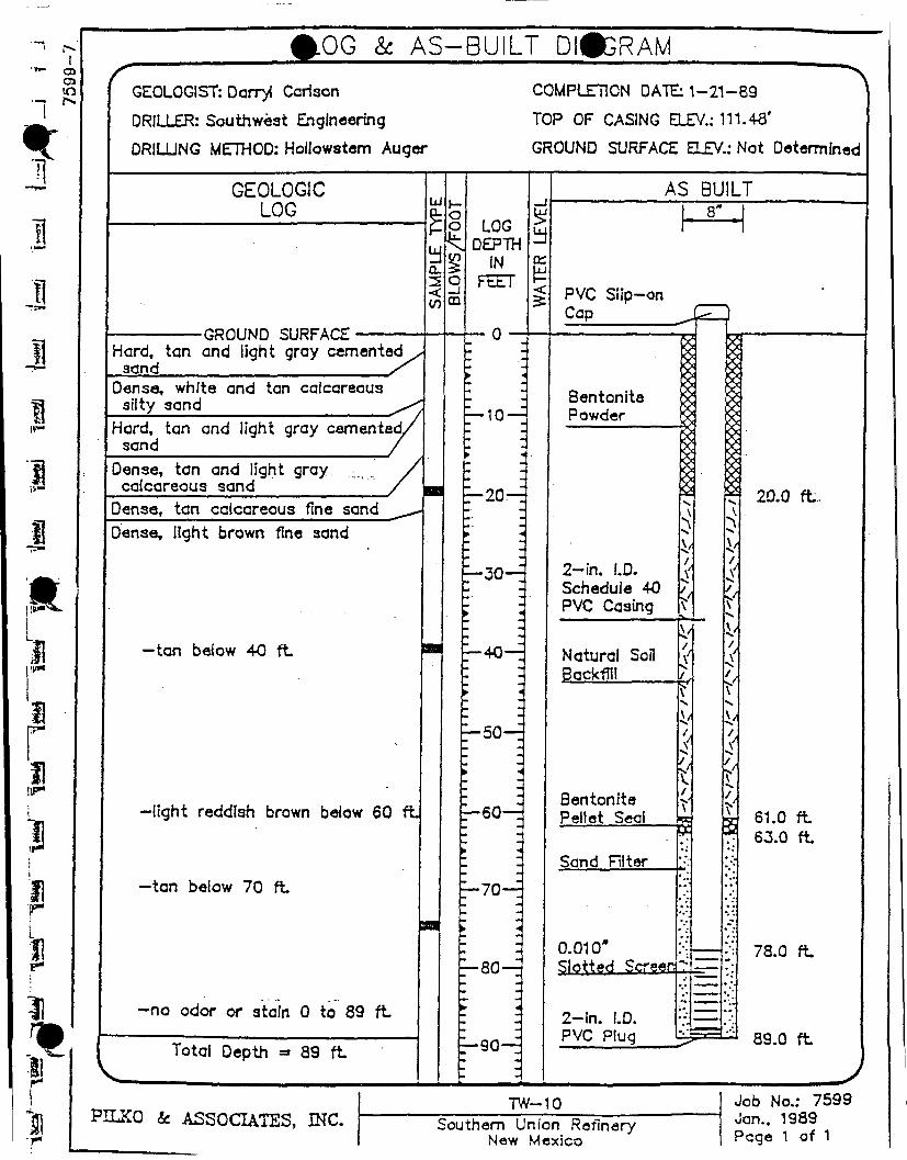
#.QG & AS-BUILT DIAGRAM
GEOLOGIST: Darryi Carison
DRILLER: Southwest Engineering
DRILLING METHOO: Hollowstem Auger
COMPLETION DATE: 1-21-89
TOP OF CASING ELEV.: 111.48'
GROUND SURFACE ELEV.: Not Determined
GEOLOGIC LOG
•GROUND SURFACE Hard, tan and light gray cemented
3and _ / Dense, white and tan calcareous
slity sand Hard, tan and light gray cemented/
sand Dense, tan and light gray calcareous sand
Dense, tan calcareous fine sand Dense, light brown fine 3and
—tan below 40 ft
-light reddish brown below 60 ft
—tan below 70 ft
-no odor or stain 0 to 89 ft
Total Depth =• 89 f t
i— o o LOG
DEPTH IN
FEET
—10 —
•20—
•30—
—40-
• *
—50—
• t
_-60-_
•70—
—80—
—90—
AS BUILT
PVC Slip-on Cap
Bentonite Powder
2-in. I.D. Schedule 40 PVC Casing
Natural Soil Backfill
Bentonite Pellet Seal
Sand niter
8"
fc r
0.010" Slotted Screen
2-ln. I.D. PVC Plug
5
20.0 ft.
61.0 ft 63.0 ft
78.0 ft
89.0 ft
PILKO & ASSOCIATES, INC. TW-10
Southern Union Refinery New Mexico
Job No.: 7599 Jan., 1989 Page 1 of 1

r <|PG & AS-BUILT DIGRAM
GEOLOGIST: Darryi Carlson .
DRILLER: Southwest Engineering
DRILLING METHOD: Hollowstem Auger
COMPLETION DATE: 1-21-89
TOP OF CASING ELEV.: 103.88'
GROUND SURFACE ELEV.: Not Determined
GEOLOGIC LOG
-GROUND SURFACE-Hard, tan and light gray cemented,
3and Dense, tan and light gray calcareous
sand
Dense, light brown calcareous silty fine sand
Dense, light brown silty fine sand
—weakly cemented 35 to45
—with weakiy cemented seams 45 to 50 ft
Dense, tan fine sand
—weakly cemented 56 to 63 f t
-cemented 63 to 68 ft
—moist below 69 ft
—no odor or stain 0 to 79.5 ft
Total Depth = 79.5 f t
t -o a
— 10-
LOG DEPTH
IN FEET
•20—
• *
•30—
—40—
— 50-
r-60-E
•70—
• -
—80—
E - 9 0 - .
AS BUILT 8"
PVC Slip-on Cao
Bentonite Powder
2-in. I.D. Schedule 40 PVC Casing
Natural Soil Backfill
7
Bentonite Pellet Seal
Sand Filter
0.010" Slotted Screen 2-?n. I.D. PVC Plug
15.0 f t
61.0 ft 63.0 ft
-1 69.5 ft
79.5 ft
PILKO k. ASSOCIATES, INC. TW-11
Southern Union Refinery New Mexico
Job No.: 7599 Jan., 1989 Page 1 of 1
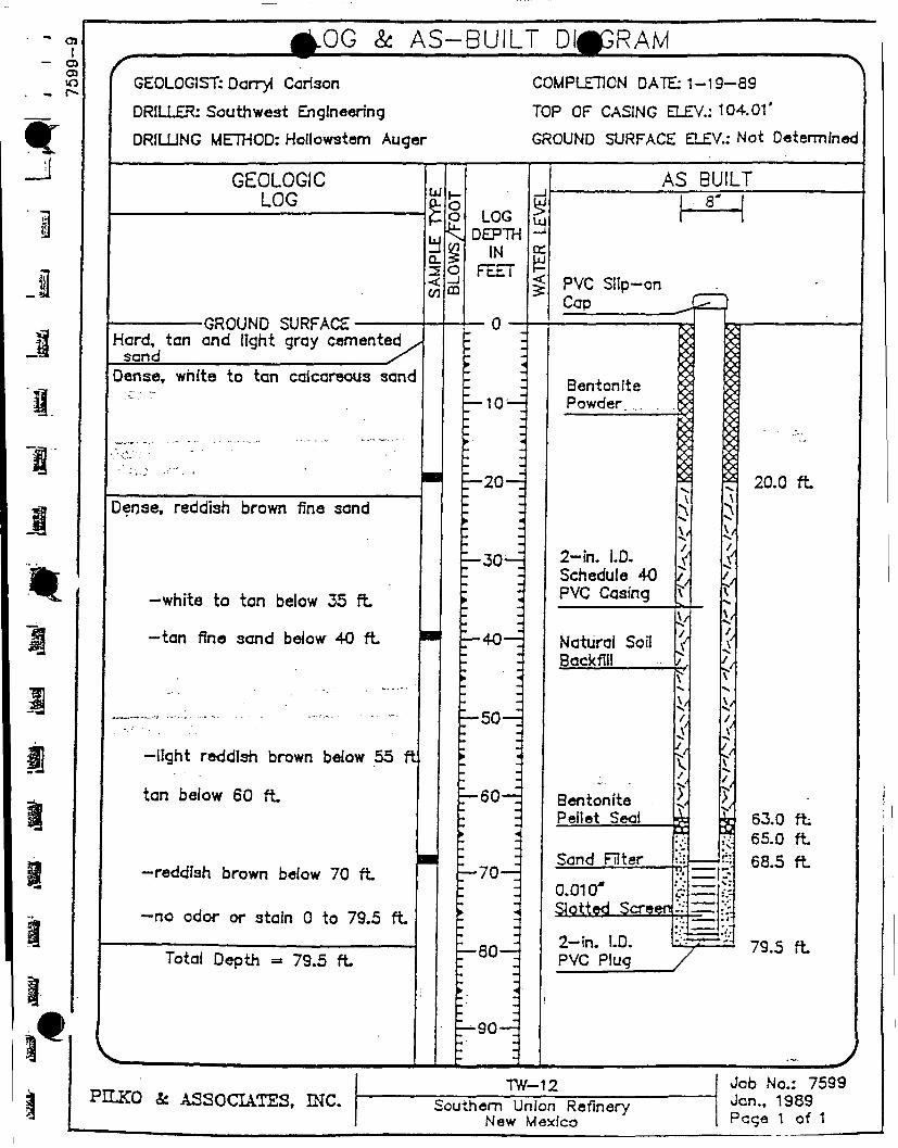
OJ jb-OG & AS-BUILT DIAGRAM
GEOLOGIST: Darryi Carlson
DRILLER: Southwest Engineering
DRILLING METHOD: Hollowstem Auger
COMPLETION DATE: 1-19—89
TOP OF CASING ELEV.: 104.01'
GROUND SURFACE ELEV.: Not Determined
GEOLOGIC LOG LU
•GROUND SURFACE Hard, tan and light gray cemented
sand y Dense, white to tan calcareous sane
Dense, reddish brown fine sand
—white to tan below 35 ft
—tan fine sand below 40 ft
-light reddish brown below 55 ft
tan below 60 ft
-reddlsh brown below 70 ft
-no odor or 3tain 0 to 79.5 f t
Total Depth =» 79.5 ft
o o LOG
DEPTH IN
FEET
— 10 —
•20—
•30—
_-40-_
—50—
• *
E-60—
• *
—70—
—80—
•90—
AS BUILT 8"
PVC Slip-on Cap JP~)
Bentonite Powder
2-in. I.D. Schedule 40 PVC Casing
Natural Soil Backfill
Bentonite Pellet Seal
Sand Rter
0.010* Slotted Screed -
2-in. LD. PVC Plug
20.0 f t
63.0 f t 65.0 ft 68.5 ft
79.5 ft
PLLKO _fc ASSOCIATES, INC. TW-12
Southern Union Refinery New Mexico
Job No.: 7599 Jan., 1989 Page 1 of 1

LOG & AS-BUILT DIAGRAM
GEOLOGIST: John Buchanan
DRILLER: Southwest Engineering
DRILLING METHOD: Hollowstem Auger
COMPLETION DATE: 1-17—89
TOP OF CASING ELEV.: 99.30*
GROUND SURFACE ELEV.: Not Determined
GEOLOGIC LOG
•GROUND SURFACE Hard, tan and light gray cemented
sand Dense, tan fine sand
- m o i s t at 15'
o o LOG
DEPTH IN
FEET
-moist to wet below 70 ft
- n o odor or stain 0 to 77 f t
— 10 —
_ - 2 0 - _
— 3 0 —
— 4 0 —
Total Depth = 77 f t
• 50—
'—60—.
— 7 0 —
— 8 0 —
'—90—.
AS BUILT 8'
PVC SHp-on Cap
Bentonite Powder
2 - I n . I.D. Schedule 40 PVC Casing
Natural Soil Backfill
Bentonite Pellet Seal
Sand Filter
0.010" Slotted Screen
2 - i n . I.D. PVC Plug /
20.0 f t
61.0 f t 63.0 f t
76.0 f t
77.0 f t
J PLLKO ck ASSOCIATES, INC.
TW-13 Southern Un icn 9»-nn»r->/
Job No.: 7599 Jen., 1989

I P G & AS-BUILT D#GRAM
GEOLOGIST: Darryi Carlson
DRILLER: Southwest Engineering
DRILLING METHOO: Hollowstem Auger
COMPLETION DATE: 1-16—89
TOP OF CASING ELEV.: 96.00'
GROUND SURFACE ELEV.: Not Determined
GEOLOGIC LOG
•GROUND SURFACE [Hard, tan and light gray cemented
sand
I Dense, tan fine sand
—with occasional thin cemented seams 20 to 25 f t
-weakly cemented 28 to 32 ft
—with occasional cemented seams 32 to 38 ft
-cemented 38 to 40 ft
-weakly cemented 62 to 65 f t —mol3t below 62 ft —wet below 65 ft —with thin cemented seams
66 to 68 ft. —no odor or stain 0 to 74 ft
Total Depth = 74 ft
o o LOG
DEPTH IN
FEET
UJ
a_
— 10 —
— 2 0 - .
—30-
—40-
— 5 0 —
—60-_
— 7 0 —
—80—
—90—
AS BUILT
PVC Slip-on Cap
Bentonite Powder
2-in. I.D. Schedule 40 PVC Casing
Natural Soil Backfill
Bentonite Pellet Seal
Sand Filter
0.010" Slotted Screen
2-In. I.D. PVC Plug
20.0 f t
51.0 f t 53.0 f t
64.0 ft
74.0 ft
PILKO ck ASSOCIATES, INC. TW-14
Southern Union Refinery New Mexico
Job No.: 7599 Jan., 1989 Pcge 1 of 1

BRUCE KING GOVERNOR
State of New Mexico ENVIR ON ME NT DEPAR TMENT
Harold Runnels Building 1190 St. Francis Drive. P.O. Box 26110
Santa Fe, New Mexico 87502 (505) 827-2850
OIL COHSERV ,N DIVISION REC: . ED
'9i w n m 8 i3
JUDITH M. ESPINOSA SECRETARY
RON CURRY DEPUTY SECRETARY
M E M O R A N D U M
TO:
FROM:
DATE:
RE:
David Boyer, OCD
Louis W. Rose, Deputy General Counsel, NMED
May 20, 1991
Southern Union Refinery, Lovington
Attached i s a copy of a l e t t e r I received from a law fi r m i n New York concerning the Southern Union Refinery s i t e i n Lovington. I t appears that the records she seeks are probably i n your f i l e s , not NMED * s. I n my response I have advised her to contact you d i r e c t l y .
Enclosure
cc: Ron Curry, Deputy Secretary Kathleen Sisneros, Director, W&WMD
^'i»r% ******* ^ k

M O U N D , C O T T O N & W O L L A N C O U N S E L L O R S AT LAW
O N E B A T T E R Y P A R K P L A Z A
N E W Y O R K , NY 1 0 0 0 4
WRITER'S D I R E C T DIAL
(212) 8 0 4 - 4 2 7 0
(212) 8 0 4 - 4 2 0 0
TELEX: 6 4 - 9 0 6 3
FAX: (212) 3 4 4 - 8 0 6 6
RECEIVED
MAY 1 V i 9 9 l
LEGAL 71 S T E V E N S O N S T R E E T
S A N F R A N C I S C O , C A 9 4 1 0 5
(•4IS) 8 8 2 - 4 1 7 7
May 13 , 1991
L O N G B O W H O U S E
- 2 0 C H I S W E L L S T R E E T
L O N D O N ECIY 4TY
( 0 7 I ) 6 3 8 - 3 6 S e
CERTIFIED MAIL. RETURN RECEIPT REQUESTED
Mr._Lon Rose-, Esq -. Department of Environment P.O. Box 26110 Santa Fe, New Mexico 87502
Re: Southern Union Lovington, New Mexico Refinery Our F i l e No.: 383.39
Dear Mr. Rose:
Pursuant to the Freedom of Information Act, we request that your provide us with a l l documentation i n your possession r e l a t i n g t o the contamination and clean-up of the Southern Union Lovington, New Mexico Refinery located i n Lovington, New Mexico. This request encompasses but i s not l i m i t e d t o governmental records r e l a t i n g t o the discovery of the contamination, extent of the clean-up and progress of the clean-up.
We believe the responsive documents w i l l be voluminous and therefore request a l i s t i d e n t i f y i n g the documents before they are copied. I f t h i s i s not possible, kindly provide us with an estimate as to the number of boxes or quantity of documents. Should you need any further information, do not hesitate t o contact me at the above d i r e c t - d i a l number. I f I am unavailable, please speak with the attorney handling t h i s matter, Jeffrey B. Gold.
Thank you i n advance f o r your prompt assistance i n t h i s matter.
Very t r u l y yours,
MOUND,- COTRDN & WOLLAN
Lisa Panebianco Legal Assistant
LP: vr
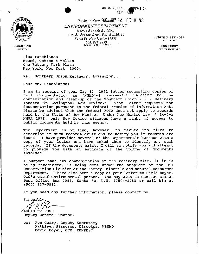
OIL CONS£R\ -^DIVISION
ENVIRONMENT DEPAR TMENT Harold Runnels Building
1190 St. Francis Drive. P.O. Box 26110 Santa Fe. New Mexico 87502
State of New M k i c W n 8 i 3
'505)827-2850
JUDITH M. ESPINOSA SECRETARY
BRUCE KING May 20 , 1991 RONCURRY DEPUTY SECRETARY
Lisa Panebianco Mound, Cotton & Wollan One B a t t e r y Park Plaza New York, New York 10004
Re:._. Southern Union Refinery:,- Lovington .
Dear Ms. Panebianco:
I am i n r e c e i p t of your May 13, 1991 l e t t e r requesting copies of " a l l documentation i n [NMED's] possession r e l a t i n g t o the contamination and clean-up of the Southern Union . . . Refinery lo c a t e d i n Lovington, New Mexico." That l e t t e r requests the documentation pursuant t o the f e d e r a l Freedom of I n f o r m a t i o n Act. Please be advised t h a t the f e d e r a l FOIA does not apply t o records held by the State of New Mexico. Under New Mexico law, § 14-2-1 NMSA 1978, only New Mexico c i t i z e n s have a r i g h t of access t o p u b l i c documents held by t h i s agency.
The Department i s w i l l i n g , however, t o review i t s f i l e s t o determine i f such records e x i s t and t o n o t i f y you i f records are found. I have provided several of the Department's bureaus w i t h a copy of your l e t t e r and have asked them t o i d e n t i f y any such records. I f the documents e x i s t , I w i l l so n o t i f y you and attempt t o provide you w i t h an estimate of the volume of documents invol v e d .
I suspect t h a t any contamination a t the r e f i n e r y s i t e , i f i t i s being remediated, i s being done under the auspices of the O i l Conservation D i v i s i o n of the Energy, Minerals and Na t u r a l Resources Department. I have also sent a copy of your l e t t e r t o David Boyer, OCD's c h i e f environmental person. You may wish t o contact him a t Post O f f i c e Box 2088, Santa Fe, N.M. 87504-2088 or c a l l him a t (505) 827-5812.
I f you need any f u r t h e r i n f o r m a t i o n , please contact me.
Sincerely ,
LOUIS WY ROSE Deputy General Counsel
cc: Ron Curry, Deputy Secretary Kathleen Sisneros, D i r e c t o r , W&WMD David Boyer, OCD, EMNRD
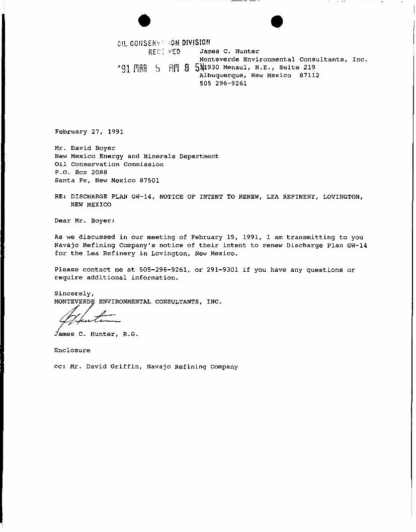
OIL CONSERVE • fOM DIVISION RE-? v'ED James C. Hunter
Monteverde Environmental Consu l t an t s , I n c . *91 PlfiR 5 f i n 8 S 4 ! 1 9 3 0 Menaul, N . E . , Su i t e 219
Albuquerque, New Mexico 87112 505 296-9261
February 27, 1991
Mr. David Boyer
New Mexico Energy and Minerals Department O i l Conservation Commission P.O. Box 2088 Santa Fe, New Mexico 87501
RE: DISCHARGE PLAN GW-14, NOTICE OF INTENT TO RENEW, LEA REFINERY, LOVINGTON, NEW MEXICO
Dear Mr. Boyer:
As we discussed i n our meeting of February 19, 1991, I am t r a n s m i t t i n g t o you Navajo R e f i n i n g Company's n o t i c e of t h e i r i n t e n t t o renew Discharge Plan GW-14 f o r the Lea Refinery i n Lovington, New Mexico.
Please contact me at 505-296-9261, or 291-9301 i f you have any questions or re q u i r e a d d i t i o n a l i n f o r m a t i o n .
S i n c e r e l y , MONTEVERDE ENVIRONMENTAL CONSULTANTS, INC.
James C. Hunter, R.G.
Enclosure
cc: Mr. David G r i f f i n , Navajo Refining Company

Under Section 3-108 of the New Mexico Water Q u a l i t y Control Commission Regulations, Navajo R e f i n i n g Company (Navajo) hereby n o t i f i e s the New Mexico O i l Conservation Commission of i t s i n t e n t t o renew Discharge Plan GW-14 f o r the Lea Refinery i n Lovington, New Mexico.
I n q u i r i e s concerning t h i s Discharge Plan may be d i r e c t e d t o :
Mr. David G r i f f i n Navajo R e f i n i n g Company P.O. Box 159 A r t e s i a , New Mexico 88210
The l o c a t i o n of the discharge w i l l be:
Lea Refinery Section 1, T. 17 S., R. 35 E. Lea County, New Mexico
The Lea Refinery i s a crude o i l r e f i n i n g f a c i l i t y t h a t has a r a t e d process capacity of 37,500 b a r r e l s of o i l per day. The r e f i n e r y was constructed i n 1974, processed petroleum products u n t i l 1984, and has been shut down since 1984. Navajo intends t o r e c o n d i t i o n and r e s t a r t the r e f i n e r y , and t o produce petroleum products f o r sale as w e l l as feedstocks f o r i t s A r t e s i a , New Mexico f a c i l i t y .
The Lea Refinery w i l l produce approximately 200,000 gal l o n s per day of wastewater t h a t w i l l be disposed of i n 1 or 2 o f f - s i t e Class I i n j e c t i o n w e l l s , operated by Araho, Inc. and located i n Section 1, T. 17 S., R. 36 E. These w e l l s w i l l i n j e c t wastewater i n t o e i t h e r the Abo Formation at a depth of approximately 8000 f e e t , and/or the Fusselman Formation at a depth of approximately 11,000 f e e t . Natural waters i n these formations are b r i n e s , w i t h t o t a l d i s s o l v e d s o l i d s (TDS) contents i n excess of 40,000 m i l l i g r a m s per l i t e r ( mg/l).
Wastewater w i t h an average TDS content of 1300 mg/l w i l l be generated by water treatment, c o o l i n g and steam generation, crude o i l d e s a l t i n g , s t r i p p i n g , and other r e f i n i n g processes. P r i o r t o discharge t o the i n j e c t i o n w e l l , the wastewater w i l l be t r e a t e d t o remove free hydrocarbons and any p o t e n t i a l l y hazardous l e v e l s of organic c o n s t i t u e n t s .
Groundwater i n the shallowest a q u i f e r under the r e f i n e r y i s at depths ranging from 60 t o 80 f e e t , and has an average TDS of 450 mg/l.