Embed Size (px)
Citation preview

f/ -
@
f
G E N E R A L E L E C T R I C C O M P A N Y
D R I V E S Y S T E M S P R O D U C T D E P A R T M E N T
S A L E M , V A . 2 4 1 5 3
INSTRUCTIONS GEK-28673
SPEEDTRONIC" CONTROL
CALTRRATOR HANDBOOK
4 t h Editton J u n e 2 3 , 1 9 7 8
PROPRIETARY INFORMATION OF THE GENERAL ELECTRIC COMPANY
IS CONTAINED IN THESE INSTRUCTIONS
* Trademark of General Electric Company* Trademark of General Electric Company
GENENil @ E L E C T R I C


Sheet -1
CONTENTS
Introduction
I. Features
A. Physical
B. Signal Sources
1. Millivolt
2. Variable Frequency
39 Standard Voltage Source
4. Current/Volta,ge
5. Test Pot and Switches
6. Sequence Switches
C. Patchboard
II. Ca.libration
A. General
1. Connections
2. Instrumentation
3. References
4. Techniques
B. Signal Sources
1. Thermocouple Simulation
c. Sample Calibration Procedure
III. Revision Variation Definition
IV. DEVICE INFORMATIOE
A. Calibrator, I:c4g88Aloo, Shs. 3 .l-3.23
B. 1c36oo~~ss, shs. 3.0-Fl.
1c36ooscz~, Shs. 3.0-Fl.
Page
3
4
4
4
4
5
6
6
6
7
8
10
10
10
10
11
12
16
16
17
18
IC36OOSVFA. Shs. 3.0-Fl.
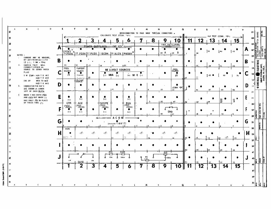
c. Patchboard Layout


Sheet - 2
$ INTRODUCTION
The SPEEDTRONIC* Control calibrator provides a convenient method of accessing
important variables within a SPEEDTRONIC* control system and supplying signals to t .he
panel to simulate the input from sensors external to the panel. The calibrator
patch board and the two connectors whichplug between the SPEEDTRONIC* control___-
“page” and calibrator are the means for reading out and inputing signals to thecontrol. The calibrator is dedicated to the SPEEDTRONIC* controls by its plug-in
feature and by the fact that it is powered by the control to which it is connected.
Its signal sources are universal types however; (such as millivolt, variable
frequency, current and voltage) which may be used to calibrate special circuits
that may be part of-a particular SPEEDTRONIC* control application.
These instructions cover the calibrator and how it may be used to calibrate a
SPEEDTRONIC* control system. The actual procedure for calibrating and the settings
are contained in the Control Specifications. The System Elementary drawing is
also needed for calibrating. The interconnection between the calibrator and the__-_--- -.._- -_- -_----_--_--_.__--
---control system is shown on the 42 series sheets of the System Elementary.-..___._---___-__----------.
On the last sheet of this publication is a patchboard layout showing points on
the patchboard which are generated within the calibrator. The System Instruction
book will be useful for both general information about the system and specific
information about each piece of equipment and should be referred to in the event
trouble-shooting, changes, or repair need be accomplished.
This calibrator may be used to calibrate any Mark I or Mark II Speedtronic* control
panel. The calibrator is presently in its 3rd revision, but changes have been
minor. For revision variations, refer to Section III, Revision Variation
Definition.
* Trademark of General Electric Company

Sheet - 3
SPEEDTRONIC* CONTROL CALIBRATOR ICF37009" See Revision Variations Section III

I. FEATURES
A. PWSICAL . i,
The calibrator is packaged in a carrying case with additional space
available for a digital voltmeter and frequency counter. It is connected
to the SPEEDTRONIW control panel by means of 2 connector cables which
plug into slots 'A" and "Brc in the calibrator and 2 slots on the "page"
designated "CALIBRATOR TEST" and "AUX TEST" respectively. Each connector
cable contains 51 wires.
The circuits for power supply, signal sources etc. are built on
DIRECTOMATIW II cards and plugged into the card slot rack along with
the connector cables A and 3. Card Slot C contains SVFA on which the
circuits for the 2 variable frequency oscillators are built. Card Slot I)
contains SCZh on which the 2 millivolt sources and voltage/current source
are built. The EPSS card in slot E contain a-SOVDC to-12VDC power supply.
B. SIGNAL SOURCES
1, The millivolt source is designed to simulate low level signals such
as turbine exhaust thermocouples over a range 0-50MV with FINE adjust-
ment of 23 MV.
a. There are two sources.
b. Their respective power is derived each from one of the 3 KHZ
power oscillators in the SPEEDTRONIC% page.
c. Outputs are available on patchboard @WA, C4 and C5; MVB, C6
and C7).
* Trade Nark of General Electric Co.

Sheet - 5
I. FEATUHES - (continued)
B. SIGNAL SOURCES - (continued)
a. "S$:c switch can be used to switch each source to either
position on the patchboard.
SWITCH DOWN MV#l AT MY-A; MV#2 AT MVB
SWITCH Up MV#2 AT MVA; MV#lAT MVB
This allows the two sources to be set up at convenient end points,
for instance, when calibrating gain and offset on the temperature
amplifier.
e. Circuit details: IC~~OOSCZA
2. The two Variable Frequency sources are 10 to 11 volt peak to peak
variable from 15 Hz to 12.5 KHZ Sine wave (66.7 millisec. to 80.0
microsec). The sources may be used to simulate a speed signal from
a"pulse tach" ma.gnetic pick-up in order to calibrate pulse rate to
analog circuit and speed control loop.
a. Fine adjustment + 25OHZ.
b. Output available on patchboard
(FRE.2, #lat Cl and FREQ #2 at Cl0 with respect to ACOM)
c. Circuit 5s powered by 1c36oo~~ss MINUS jOV TO MUNUS 12V converter
unless MINUS I2 VOLT supply is available in SPEEDTRONIC* control
in which case MINUS 5oV is not available; it also requires plus
12V supply from SPEEDTRONIC* control.
d. Circuit details IC36OOSVFA.

Sheet 6
_ I
I. FEATURES - (Continued)
B. SIGNAL SOURCES - (Continued)
3. The Standard voltage sources are approximately 6 volts and 20
millivolts. The actual values will be recorded on the 1~3600~~~~
card on which the terminal binding posts are located. These
standard sources may be used to
voltmeter or scope.
4. The combination CURRENT/VOLTAGE
calibrate instruments such as
source makes available a current
and a voltage to simulate pressure transmitters, etc.
a. With 50 volt bus available in control:
current, 0-50ma (500n MAX load); voltage 0-34VDC
With only 12 volt bus available in control:
current, O-50ma (50 n MAX load); voltage 0-LIVDC
b. Sources are adjustable by coarse and fine pots marked "current".
5.
c. On Patchboard:
Voltage source located D2
Current source located C2
To read current with voltmeter
precision resistor (10 mv/ma).
d. Circuit details IC~~O@SCZA
There are two switches, a resistor
configuration.
connect C2, (positive) to D2 across
pot configuration and a resistor
a. SW9 s.p.s.t. switch could be used as a logic level switch
DC()M = "0" ; p12TJ = "1" ; or contact closure to P28v.
(patchboard points Fg and FlO).

I.
Sheet - 7
aFJWFURJZS - (Continued)
B. SIGNAL SOURCES - (Continued)
5. (Continued)
b. SW10 s.p.d.t. switch could be used to switch the voltmeter
between the two overtemperature channels to facilitate
simultaneous calibration. (patchboard points Jl, 52, and 53).
c. Pot and resistor configuration may be used to set up a test
voltage or with 3KEZ oscillator to make a test vibration
signal.
d. Resistor configuration may be used to simulate flame and no
flame condition of impedance expected from detectors to "Ball
park" the detector sensitivity prior to starting. The 10K
connected between Pl2V and "VERY FAST" counter rate will speed
up the digital setpoint counter for calibrating purposes, &I some-.
6. There are 7 sequence switches which may be used to simulate points
in the start-up mode. Certain portions of the control are operable
only when the turbine has come up to a given point during start-up.
Some or all of these switches may be wired in a given application
if they are needed in order to calibrate the unit. Refer to sheet
42Iof the elementary for switch usage.
IMPORTAI'TT: These switches normally must be turned off {down)
when starting up or running the turbine with the
calibrator connected.

Sheet - 8
FEATURES - (Continued)
C. PATCHBOABD
The patchboard layout is shown on the final sheet of this publication
(fold out ) . Patchboard points are connected to circuitry within the
calibrator such as sources, test switches, and components; or jacks
along the right side of the calibrator to allow hook up of instruments;
or through the connector cable to the SPlZEXYCRONIC* page. The points
on the patchboard which are wired through the connector to the SPEEDTRONIC*
pege are shown in The System Elementary for the specific control on
the 42 series sheets.- - -
The 10 x 10 section of the patchboard, points Al by JlO, are connected
to the SPEEDTRONIG* page through "Corm A", the "calibrate test" connector,
and the remaining 5 x 10 section, points All by 515, are connected by
"Corm B", the "Aux test" connector.
1‘ On the layout sheet the pin numbers to which the input/output are
connected appear as the small number in the lower left hand corner
of each block.

Sheet - 9
II. FEATURES - (Continued)
c. PATCHBOARD - (Continued)______~~._______.
2. The "calibrate test" connector and the "auxiliary test" connector-.--_--- - - - - _._.-_- .----'is shown on the 42 series sheets of the system elementary_--- .______ - _----- - -
for each unit. These sheets name and reference the point in the
circuit to which the point is connected - if it is used.
3. To facilitate working from the system elementary to the calibrator
for a particular point, the coordinates on the patchboard are___...._ ----_------~
given adjacent to each point r& the system elementary. ---.-----____Lp- --_--- --~ -__

Sheet - 10
_-- -.-.-.-_~- .--__11. TYPICAL CALIHRATION-__-___- .~
A. GEXERAL
Once power is applied after preliminary checkout, the unit is
ready for calibration. Plug in the.calibrator and check that proper
power is available at the patchboard points Al thru A6, and 3KHZ- - -__
power oscillators A9 and A10 (refer to patchboard layout - - -
of the turbine control elementary).
1. Necessary Connections for SPlZEDTRONIC* Calibrator
Connector "A" from calibrator should be connected to "calibrate test
card slot" on SPEEDTRONIC* page.
Connector "B" should be connected to "Aux. Test Card Slot" on
SPEEDIRONIC* page.
Refer to job elementary to determine location of these two card slots- - - -
(normally shown on sheet 421 of elementary).
2. -X&iZtib~iT%~GieXZ%~&i----_.-
- - . .._
-__--~~-__-___Other- instruments that can be suppl_i&-with-the calihratorare:_______.. _~--I_--..-~..-~_~--.-.--
.~_ .Digit&Voltmeter. 4-Digits.-(3$ Digits)_~_. _. _- -.-- ~-- --~------ -- -Counter 20Hz - 8OMHz 7 Digits
In additional to the SPEEDTRONIC* calibrator, other devices that
Multi Meter - 20,000 Ohms/Volt
Such as - Triplett Model 630 *
or Simpson Model 270 -1>._~._--~-- .-
OsciLlos_cope.~~lfor__traub.leshooting only)
Such as - Tektronix 453
SPEEDTRONIC* Protective Logic Test Aid Module - catalog #277A6557Gl.

Sheet - 11
II. TYPICAL CALIBRATION - (Continued
A. GENERAL - (Continued)
3. References:
a) Instruction Book - Comprehensive information, one lines, locations
of adjustments.
b) Job elementary diagram - Circuit, pin numbers, card location,
pot. identification.
c) Turbine Control Specifications - Design and application
parameters, device settings,
calibration procedure.
4. Techniques and Procedures
a) Use a voltmeter to determine logic level of signal.
11 (10 = OV to .4V (High thresho&~"O" up to 1.5~)
I1 II1 = 4.75v to la?
b) Definition of Range, Span, Zero, Offset, Gain
Given: Exhaust temperature variation of 3000 and 1000° which
produces signals of 1.83 Mv and 23.4l~V;
Signal span = 23.41 IW - 1.83 IVN = 21.58 MV
Signal range = 1.83 MV to 23.41&W
Signal zero or offset = 1.83 MV
If this signal is amplified to l.CV and 4,5V,

Sheet - 12
.--_--_____._II. TYPICAL CALIJlRATI.ON - (Continued-. -
A. GENERAL - (Continued)
4. (Continued)
d
output span = 4.5-v - l.w = 3.5v
Output range = l.W 4.5V
Output zero or offset = l.W
Amplifier gain = Output span
Input span
= 3.7.7 = .1624 v-
21.5&V Mv
Adjusting "zero" and t'gaint' of an amplifier (ZERO: OFFSET)
Theoretically you should adjust the gain first, then adjust
the zero because gain affects zero and zero does not affect
gain. However, since many amplifiers are not perfect and
since you want to start in the right "ball park", an easier
and more practical method is as follows:
Using the va,lues in the example (b) above:
1. Apply 1.83 Mv to input.
2. Adjust zero for I.W output.
3. Apply 23.41 MV to input.
4. Adjust gain for 4.5 output.

Sheet - 13
__-.-~ __. ____-..-_--.------11. TYPICAL C~~B&$~~ON_z_@onticlantinued)-
A. GEKERAL - (Continued)
4. (Continued)
c) (Continued)
5. Apply 1.83 MV to input.
Note : Because of the gain adjust, the zero has moved. .
6. Readjust zero for l.OV output.
7. Apply 23.41 Mv to input.
8. Readjust gain for 4.5 output.
Note : The amount of readjustment
adjustment.
decreased with each
9. Repeat 1 to 8 until no readjustment is necessary.
d) "Nulling" or "balancing" the summing junction.
1.
2.
Within the stable operating range of an operational amplifier,
the sum of all currents to the summing junction is zero.
Many of the amplifiers used herein have integrating feedbacks.
This means that, if the net current to the summing junction
is negative, the output volts will continue to rise and con-
versely, a net positive summing junction current will cause
the output volts to continue to decrease. When the sTunming
junction current is zero, the output will. stop integrating
and the volts will remain constant.

Sheet - 14
___.___ -.- _--. .---------_ .-II. TYPICK'CALIBRATION - (Cont>&ued)
I---.--
A. GENERAL - (Continued)
4. (Continued)
d) (Continued)
3. A voltmeter on the output of the amplifier can be used to de-
termine when the integration stops. However, an easier method
is to use the function indicating lights. For example, consider
the temperature control card STKA and we want to set the iso-
thermal base reference to 1OOOoF.
4 Input an exhaust temp. signal of 1OOOoF. (4.5V @ pin 17)
b) Quickly rotate and counter rotate base reference pot. R95
so that temperature control indicating light goes on and
off. (Note: Pot. movement causes amplifier to integrate
voltage up or down. Light driver is voltage sensitive;
above 28V = Light out and below 28V = Light on). As you
rotate and counter rotate and the light goes on and off,
reduce the amount of excursion until the light just stays
on. Set the pot. at the midpoint of this minimum excur-
sion.
4 The summing junction is now "nulled" for this particular
setting.

Sheet - 15
___----e-m-
II. ??@ICAL CALIBRATION - (Continued)
A. GENERAL - (Continued)
4. (Continued)
e) Inputs and Outputs
1. Frequently, the Control Specification will refer to pin numbers
on various cards, for monitoring, logic forcing, or even
signal insertion. This does not mean that you should work on
that pin; on the contrary, you should avoid working on the
pin itself. Rather, you should refer to the pin and the card
on the Turbine Control elementary and, if possible, determine
some more appropriate point, on the same point in the circuit
as the pin, but physically more accessible. For example, the
point may be available on the calibrator patchboard; it may be
available on a card front; it may be an incoming signal with
isolation LED
element which
front; it may
indication.
2. Logic Forcing
indication; it may be the output of a SL;EH
has LSD indication and is forcible from its
be the output of a STDC element which has IZD
The SLEH element can be forced to a "1" or "0" from the front.
All elements may be forced "0" on the outputs, but must never
be forced to "I.".
i.e. You may jumper any logic signal to D-COM (to force "0")
but must never jumper a signal to Pl2Y or Pfjiv to force "1".

Sheet - 16
____-__-._. --.---L_._-__-
II, TYPI~&.&..IER&TT~N - !Con%inued)
B. SIGNAL SOURCES
The signal source outputs appear on the patchboard so that they may be
connected to any other point on the patchboard by jumpering with the
miniature plugs supplied with the calibrator. Sources may be accessed
for use into points not on the patchboard by patching them to large
jacks such as Y?COPE", "DVM", or YTR". These jacks will accept
standard "BANANA" plugs or may be wired to by clamping the wire under
terminal binding post.
1. MILLIVOLT for thermocouple simulation may be accomplished 3 ways:
a. If a cold junction compensation network is available for the
particular type of thermocouple to be simulated (such a
J type Iron-Constantan; K type Chromal-alumal), it may connected
with the proper thermocouple wire between the source and the
T. C. amplifier. Standard thermocouple tables can be used to
convert from the temperature desired to the'millivolts which
must be measured.
b. If the cold junction compensation network is not available the
above method will work provided the ambient temperature is
measured and difference between ambient and 3Z°F (which is the
reference used in the tables) is subtracted from the table value
of millivolts for the particular temperature desired to simulate.

Sheet - 17
____---- _ ----II. TYPICAL CALIBRATION - (Continued)
B. SIGNAL SOURCES - (Continued)
1. c. If a temperature indicator such as the one on the SIEEDTRONIC*
control panel is available the temperature may be read directly.
The amplifiers and trips may then be set without measuring
millivolts .
c. SAMpI;E CALIBRATION PROCEDURE
The following is a brief description of the steps required to use the
calibrator; as one example let us consider the case where the overspeed
trip points are to be checked. The actual detail is defined in the
Turbine Control Specification; the following is only a description
of how to find your way around:
1.
2.
3.
4.
5.
6.
7.
8.
Calibrator must be plugged into the panel '
The panel must be powered up.
Refer to the Turbine Control Elementary Index, sheet AOO, and
determine which sheet the "Overspeed Protection" is located on.
Refer to the Overspeed Protection circuit in the Turbine Control
Elementary
Refer to the Turbine Control Specification for the details
on settings and procedure.
The control specification will typically say "insert a speed
signal of X frequency to the Overspeed Protection Card, pins
Y:, Z.+'
Refer to the elementary Overspeed Protection circuit and look
for a cross reference to sheet 42~ or 42!c.
Follow the cross reference to sheet 42~ or 42C and determine
the corresponding calibrator patchboard location; one position

Sheet 1.8
per Overspeed Protection card. The return is via A-COM on-. -
Patchboard Gl thru G-10.
9. Refer to sheet 42D of the elementary, the patchboard layout.
Pick out a frequency source - Cl or ClO.
10. Jumper the frequency source to the patchboard position of step
8. The return (COM) is taken care of internally.
11. For monitoring, jumper El to the frequency source and Fl to A-COM
(ie. Gl). This puts the frequency signal on test jacks C?; (+)
and (-); These test jacks will accept a standard plug for frequency
monitoring with a counter.
12. Adjust the frequency with the "COURSE" and "FINE" Frequency
adjusting Potentiometer on the Calibrator; The potentiometers
are clearly labeled.
13 l Cheek the Overspeed Protection function as defined in the Turbine
Control Specification.
III. REVISION VARIATION DEFINITION__--
The calibrator is presently in its 4133revision. Changes have been minor
and have been made to make the calibrator more versatile. The revision
number is not on the nameplate, but the revision of any particular calibrator
is readily apparent from the following:
REVISION 1: The original form used nomenclature on the switches as illustrated
on sheet 3.7 Also it has seven test jacks on the right hand side of sheet 3;‘:
REVISION 2: Added two test jacks, AUX (f), (-), wired to patchboard points
E2, F2 respectively and spaced all test jacks to take a standard size plug.
REVISION 3: The switch designations were changed from names to switch numbers,-__- ______ -----
i.e. SW1,2 etc. Note that the switch numbers on the calibrator drawings were- - -
changed to facilitate a left to right flow of switch numbers..p---- -..-- ------ - --- -- - --...-- ____ This change allows__ _. ____ _ _ _.__ ___-- - ----------
__.______._ - _._~ - ._ -.--- .-- -- ----.- -- .---....-. ~_

Sheet 19
any one switch to be used for different functions from one panel to another.
The switch's function is defined on sheet 42Eof the panel elementary.
The switch numbering is as follows:
SW1 SW2 SW3 SW4 SW5 sw60 0 0 0 0 0
SW7 SW8 SW9 SW100 0 0 0
In addition to the change in switch nomenclature, 12 additional wire runs1
from the panel to the patchboard have been added as follows:
connector A: pins 49, 51
connector B; Pins 1, 2% 23, 24, 27, 28, 29, 30, 50, 51
This further increases the capability of the calibrator. Your calibrator will
have these extra runs if it has switch numbers on the nameplate; it will
not have these runs if the switches have names as illustrated on sheet yl“------l
Any panel may be calibrated with any calibrator with the following reservations 1limitations:
(4 Switch designation may be confusing, but are defined above.
(b) The 3.2 interconnecting wires defined above will not be on revisions
1 and 2 and may be a problem when a Mark II Industrial panel is
to be calibrated with a revision 1 and 2 calibrator. This limitation
may be identified by referring toyhe-mzessheets ofXi& Paielementary.
-----.---.-_
A modification kit is available to take care of limitations (a) and
(b) where needed. 4
(cl The voltage/current source on IC36OOSCZA, Rev. A is not capable
of providing a 50 MA pressure signal when used on a Mark 11
panel. (It's O.K. on Mark I>. If this signal is required for__~-
a Eark II panel, a Revision B must be obtained._ _-_------- ^~--- _... _. _ _
REVISION 4: The "TEST" pot RHll was changed from a 1 turn lOOK_ _.-_-_ __~__ _-__-_- _--_- -- -... -.. - .- ____ __.

03
05
07
09
11
13
IS
17
19
21
23
25
!7.
29
31
I3
1s
I7
I.9
I1
13
I5
I7
19
5 1
s IC.NAL DEF It: If I OfI Am LOCAT ION
S7l~IBOL tw4E CONN A PATCH BObRDSTD. A L T . P I N No. LOCAT 1 ON
DCOM DIGITAL COMMIN f
ACOM ANALOG COt+tJN 2P50 POSITIVE 50 VOLTS 24P28 POSITIVE 28 VOLTS 23PI2 POSITIVE 12 VOLTS 2 7
h4
Gl - 610Alh2A3
N12 NEGATIVE 12 VOLTS 29 ASN50 NEGATIVE 50 VOLTS 30 A6OSCA OSC I LLATOR A 3KC 8.4 RMS (LVDT.) 26 A9OSCB OSC I LlATOR 8 3% 8.4 RMS (LVOT) 28 I410
CALlERAlCR S IGNALSVARIABLE FREQUENCY OUTPUT tVARIABLE FREQUENCY 1 - EXTERNAL CONTROL (SIMULATfON)VARIABLE FREQUENCY OUTPUT 2VARIABLE FREQUENCY 2 - EXTERNAL CONTROL (SlMlJLAT ION)
Cl11
Cl012
PsfM CURREM SOURCE @-5Cb@jVOLTAGE SOURCE( &34V, SUPPLY SW; CL8, SUPPLY 12YCURRENT SOURCE-EXTERN CONTROL (S Ir4lJlAtlON)
WA+MVA-MvB+MYB-
MILLIVOLT SOURCE
MI LL IVOLT SOURCE
c2de14
c4C5C6c7
NOTE MVAL MV) W I T H S W I T C H S W - 1 DOkMHVB:MV2 WITH SWITCH SW-1 WWJMYArMY WITH SWITCH SW-1 UPMVBs.MVt W I T H S W I T C H S W - 1 ‘$
MVIC
rC%dER SUPPLIES
Ml LLiVOU SOURCE 1 - EXTERNAL CONTROL (SIMULATION) 13

07
09
11
1 3
15
17
19
21
23
2s
27
29
3 1
33
35
37
39
41
43
45
47
49
51
C A
tI0x8
P-
Y
4

0 3
OSSEE SH.
DI 3.6 FOR
BUSS
0 9 CONN
14POT tc3Cm PATCH
SCZAl
cuwCOA-E
!iOK
11
13
13
17
19
21
23
2s
I7
+ FINE
AC ‘34
+12” 0” -12v ,,TRt -
4FRQt
19ACPOT I c3600 PATCH CPOT
FR@ ---- d2tc36co SP2 - PATCHSVFAl .
rpD~ lAoc S I N E 45 t-R42 c l 00
O U T 2156
t - i
SVFAtF P O T
S,NE 1 9 FRQl ”
21A IAOC cyTI - -
21 00
Q 9SW-I PATCli
ACW ACDW
(SUOW I,” DOWN P O S )
1 i 2 c4
DCDU
I
-JR”SC2At
*I2 IAcmWA
-eLcjB3
366 a -
I
I
I
I
r I 8 Cl3 44ri o+
____ I38 rrv2.b
15
17
I9
51
MVBc7-Q-5x--
--
SAhfM, VA. U.S.A.

01
0 3
OS
0 7
0 9
11
1 3
15
17
19
21
23
25
27
29
31
33
35
37
39
41
43
45
47
49
51
IC36K6CZA 1
J8 Jlo
PATCH
PATCHE4 0
Fd o
JACKSrJ3
160 0 f(R)r&I4
170 -lMo
DWTEST
cf? 0
&$KS
2100 +m)
TJ6t-6 o 221, .Q -031
A L L S W I TCHES SHU&d IN D%N PCS.
C O W ASW-2 P28 C O N N A
3 5 <28~
37 <31A
SW-4
:::&rIl
SW-34 8 2
-f.K3 9 A
STDV O L T A G E 6v -__(
IC3600XzAl 2oMv __(
IA00 ov*
6
CARD FRONTJACKS
PATCHE2
Au%TESTshac3TJ8
SW-540
28~‘/=l
4 2<( 28~
1
S W 64 3
(< 3 3 a
45 < I33J
CONN A 41
37J
47J

07
09
15
17
19
21
23
25
L7
29
31
33
35
17
39
4 1
$3
55
17
I9
51
4g CONN A<
PATCH a502A
7 06
044a 07
006~
9
10
54
06~
IO*
12r
Da0
D90
040
6. 05
141)0
HI0
16~
fah
20A
22A
I490
I450
H60
14 H6.w 0
24~13 H7< 26~
0
33 Ed26~ 0
31 324 0
3oA17 e3
da 732~
1 9 3 4
34. a9<
3640
32 / 01036~ 0
16 R7\ 40A 0
360
4 D3-44A 0
21 HI\
46A0
22 c3< 46~ -
0
3 E80
SOA
GCONN A
n KPATCH
51 < 02a86
25 CO
. 046
47{oN. B
l<All
0 6 001 I
L.
IOU010
23( 124
01124< Q
14G
Cl227 4
I6a
26(t13
16~ 0
29(El I
200Hll
30x 220
36 A12-c 260 0
A
26G36- Al3\
3003
39 813
32~0
4 0 , At434a 0
41 6144 0
36042 AlS4
380 a
43 3151
4oa 0
22 tll420 0
14 El60
446
3 s-11
+----XT0
16 r!2c)
46017 Fl3
A600. Jll
11ts1 MAO1 rot E L E C T R I C CALIWATtYI
I c. N O .TAf 3.q.73
INDUSTRY CONTROL DEPT. 1 c 4 9 8aBBA , o oSALEM. VA. U.S.A. CON?. ON JH ’ SW.NO. 3*s
. . . .I r*
03
05
07
09
11
.I5
19
23
25
27
29
31
33
35
307
39
41
43
45
47
49
51
CONN. 0 PATCH CWN. 0 PATCH
13 Cl4 10 ml2\
WA0 <
04f0
9 fl5w 0
06~
1 9 Ill3
06f0
4 4 Cl2. 2 0 844< 0 0
OBA 08f
45 012 2t I415A 3
1OAL;
10F0
46 cl3 34 112<
12A 126
4 7 013 3 5 113
14Ax-
1 4 f
4 8 Cl4 2 5 I14N
16~0
16~0
49 014 2 6 115-+ 0 0
16A 18F
8 Cl1 10 J12
20A0 . 2OP
0
4 a l 2f 22A
011 J 1 34;
2 2 F
5 Cl3 1 2< 0
J 1 4
24A 24~
6 014 1 5 J154.
26A0
26f0
7 Cl5 3 2 01s.
28~ 26f
31 ct5 53.3OA
0 /- $43Of
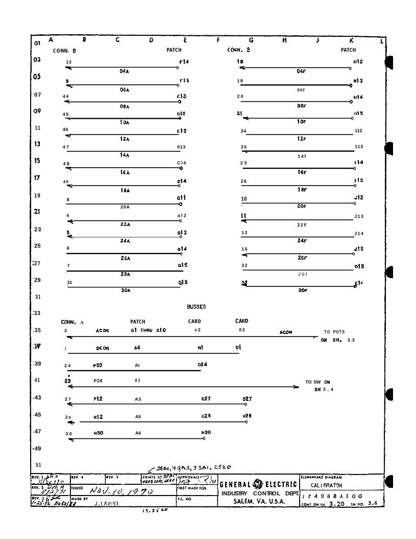
CONN. A PATCH CARD CARD
2 ACCt4 Ot THRU Glo c 2 0 2 ACOH TO POTS\ - ON Ski. 3.3
1 DCOM A4 Hl Ql
2 4 P50 At D24
2; P28 A 2 TO SW ow4 >
SH 3 . 4
2 7 PI2 A3 ~27 a27-c 0
2 s Nt2 A5 ~29 n29
-e 0
3 0 N50 A6 H30
\ 0
INDUSTRY CONTROL DEPT.

03
05
07
09
11
13
15
17
19
21
23
25
2?
29
31
33
35
37
39
4 1
4 3
45
47
49
51
PURPOSE
Is to provide a convenient, fast and accurate method for checking andcalibrating Spccltr0nf.c Panels. It is packaged in a carrying case
and is electric;llly connected withribbon cables. It provides frequency signals to calibrate the speedcontrols , millivolt signals for the temperature controls, voltage or currentsignals for the pressure sensors , precision voltage references for calibratinglnstrumcnts, and control signals are made available for monitoring.
The equipment has been designed to provide a turbine simulate functionwithin the present housing with a minimum of change.
m
1. Connectors - two card and ribbon cables with fifty one wires areused to connect the Speedtronic page with the calibrator. E a c hcable wi l l be s ix feet long . The A connector (red)is used primarily for theCalibrator asd its signals while the B connector (bluc)is used primarily formonitor ing speedtronic s ignals .
2. Directomatic 2 card rack - an eight card slot sack is provided.The two left most slots are provided to accept the connector cardsof the ribbon cable. Three slots are for the XC36OOSVF’A, SCZA, and&%~o~~ds. Three slots are provided,without receptacles,as space for future
a ) IC3~OOSVPA - voltage to frequency convertor. This card isused in conjunction with the Frq. pots to generate variablefrequency sine waves. There are two circuits OR a card.
See the card application notes for more information.
b ) IC36OOSC2A -calibrator signal source. This card containsthree di f ferent types o f c ircuit . These are:
l- one standard voltage source - 3 card front jacksare provided for meter calibration.
2 - one voltage and current source.3 - two mil l ivolt sources .
See the card application notes for more information.
c ) IC36OOEPSS - -5OV to -12Y regulator. This card converts-50V to -12V DC. It is only necessary when -12V is notavailably in the system. The card does not have tg beremoved from its slot when the -5OV’is not present.
3. Patchboard - There are two patchboards used in the equipment. Oneis a one hundred pin (10X10) Vector patchboard; the othet, a fiftypin (lOX5) Vector patchboard. The 10X10 is used primarily forcalibrator applications and the 10X5 for monitoring speedtroniccontrol signals. A quantity .of piggyback type patch plugs ateprovided for patching.

0 1 -
0 3
05
0 7
09
11
13
1 5
1 7
1 9
2 1
2 3
25
2 7
29
3 1
3 3
3 5
3 7
3 9
4 1
4 3
4 3
4 7
4 9
51
T-
4 . Potentiometera - eleven two watt potentiometer8 are provided for usewith the voltage to frequency convertors, millivolt sources, voltage,source and test functions. They are single turn pots and full counterclockwise is the minimum position.
5 . Switches - ten miniature size switches are provided for sequence simulation,thermocouple transfer and test function. All switch toggles in the up position(toward the card rack> provides a closed circuit.
6 . Test Jacks - four pairs of miniature binding posts are provided toaccomodate digital voltmeters, counters and oscilloscopes.
7. Storage - space is provided for two small instruments, instructionbook and connector cables.
8 . Enclosure - is similar to a suitcase and hinged such that it isstable in the open position.
9 . Chassis Ground is brought to a Jack (Green) which can be connected toEarth Ground.
PUNCTICNS-
Ronitor - the fifty pin patch board AlldJ15 is provided tomonitor Speedtronic signals. The procedure is to patch the desiredsignal to a test jack where it can be instrumented.
Two variable frequency oscillators are contained in the IC36OOSvFAcard. The circuits are used with four pots to achieve a variablefrequency output. By addit ion of a signal conditioning card, it Lapossible to achieve voltage control.
A variable voltage source with a. ten ohm shunt is provided. It iscapable of operating from either a +5OV supply or a +12V supply.It can be controlled from an external voltage signal for the simulateopt ion.
The Standard voltages are precision voltage references for calibratinginstruments. The two voltages are nominally +6 volts and +20 mv; theactual values are recorded on the card front during card test. Allcalibration rr\ust be done at the tacks on the card front to avoid voltagedrops.
Two millivolt sources are provided which are adjustable from O-50millivolts with 1 ohm output impedance floating with respect to thesystem. Provision is made for voltage control of mv output. for thesimulate option.

03
0 5
0 7
0 9
11
13
15
17
19
6. Switches are provided to accomplish the sequence simulation.
P O W E R
All power is supplied to the Calibrator”from the Spaedtronic Panel viathe ribbon connectors. 1 DCOM has been used as power common and ACOMused as signal common.
OPEP?TING CHECK OF ELECTRONICS
A. Install A connector in proper Speedtronic slot.
B. 1. Check to see that the necessary DC buses are present.2 . Check to see that the 8.4V 3KH voLtages are present.
(use Signal, Definition and Location chart to determineproper points).
c;. Mi l l ivo l t Source -21 1.
2 .
233 .
P u t Swi switch in the down positfon.Put millivoltmeter from MVA+ to WA- by patching ~6 to C4and F6 to CS.
25 4 .‘5 .
I76 .
29 7 .8
319 .
10.13 11.
15 12 .13 .
1 714.
19 I S .
Turn MVl-coarse pot from one e?d to the other. MV metershould vary between OV and at least +5OW.Set output at 25 mv with MVL coarse.Turn MVL fine pot from one end to the other. MV meF,:rshould vary at least 3 mv from the 25 mv reading. ’P u t SW1 switch in the up posit ion.Millivoltmeter should read OV from WA+ to MVA-. (No control from HVl Knob)Put mLlli.voltmeter from ?lVB+ to MVB- by patching E6 to C6; F6 to C7 andG5. (Remove E6 to C4 and F6 to CS and C5 to GS) .Meter should read 25 mv 53 mv.P u t SW1 switch in down position.Turn MV2-coarse pot from one end to the other. W metershould vary-between OV and at least i-50 mv.Set output at 25 mv with W2 coarse.Turn MV2 fine pot from one end to the other. MV metershould vary at least 3 mv from the 25 mv reading.Put, SW1 switch in the up position.Millivoltmeter should read 25 mv 23 mv (same reading asstep 5) . (No Control, From MV2 Knob)
13
15
Ii
19
D . Current Source -1. Patch C2 to E6 and Gl to F6.2 . Monitor between +DW and -DVMA at the test facks with a
vpltmeter.3 . Vary Curr. Coarse from one end of the pot to the other.
Voltage should vary between OV and at least 34V when i-5@?DC Ls present.Voltage should vary between OV and at least 8V when only +12VDC is present.
r
!&%?%!5 “f#~?& &- G E n E R A tfituurf~#rDf~GalY~~Lib,~~~~
rlrsr’hof fOIEtECTRlC bplicfttion I n f o .
“ 10, /4 7 3 JNDUSTRY CONTROL DEPT. Ic4988AIOOI”^“’ ‘* J, A. F,bJc CI- ix. MO. SALEM. VA. U.S.A. CoMI.OUSH 323 s*.Mo 3.22
1% z.CLP

03
05
O?
09
1 11
13
15
37
19
21
23
25
27
25
31
33
35
37
34
41
43
45
4 7
49
51
E. Voltage CO Frequency Converbor -
::
3 .
4.
6.
hatch c l to ~4 &td ~1 o CO ~4.Monitor FRQl with oscilloscope dt Scope A test jacks. A 10 to 11volt peak to peak variable frequency 15HZ to 12..SKHZ Sine WaveWill. be observed. (Lt is necessary to vary coarse pot to start wave).Vary FRQL coarse from one end of the pot to the other. Frequencyshould vary from a t t e a s t 1SHZ to 12.5KHZ (66,7MS To 80.0microsec . period).Set frequency at 6KHZ (167 microsec period). Vary FRQl finefrom one end of the pot to the other. The frequency shouldchange approx. 2fO HZ.llonitor FRO2 with oscilloscope . Remove Cl to E4, instaLl CL0 to E4. A 10to 11 volt peak to peak variable frequency 15HZ to 1:!.5KLiZ Sinewave will be observed.Vary FRQ2 coarse from one end of the pot to the other.Frequency should vary from at least LSHZ to 12.5KHZ (66.7MS To80.0 microsec. period).Set frequency at 6KHZ (167 microsec. period). Vary FRQZ finefrom one end of the pot to the other. The frequency shouldchange approximately 250 HZ.
trR’lA”@v$ypi~ EE#EBAL BLIMCYTAIV DlAGBW ~a 1 jCbra to
I>I hoa ELECTRIC A p p l i c a t i o n Info.
lNDUSTRY t6MTROl DEPT. IC4988AlOOIS. MO. SALEM. VA. U.S.A. cow. ON In. Lo wo.3~

01
3 3
a5
37
19
11
13
15
I7
1 9
21
23
!5
.I
!9
3 1
3
5
7
9
I1
3
5
7
9
it
.- - _ . - , ,
A 5 c D‘ E F G H J KSTANOARO VOLTAGE *VOLTAGE AND CURRENT SOURCE
+50V C R 6
(24) (14)Pof
SPl @) ---y-q HSl
CR5 - 68+l82ooPlCRlO - 68AR38PlPl -2wn4-~7373~892 - 2Ns320 - 68A7nmCRl4,S.d -.63A?25OPlMILLIVOLT SOURCE (2 CIRCUITS PER CARD)
CRT
CARD FRONT
-B-CR2
t3b;W)
cm OUT(36)
(34)
14% l
1. 1 SBH fir%3 IW. , RLV. 5 PIwrS TO dPtL3/72 6-r OLl ,iJzrhvb,
ELIM~WlA.LIY OIAGPAM c&L 1 BRATOR1. 2 ‘ssuEo y- 2 a - S!GNAL S O U R C E70, FOP GEH ERA1 @ ELECTRIC@J
paI FtaslM2Df
1 . 3 INDUSTRY CONTROL DEPT.MAO1 .II.C. NO.
1 c 3 6 0 0 s c z A 1JH SMITH 1338 SALEM. VA. U.S.A. CONT. ON SW. 3 -1 IN. N O . 3 . 0
D3
D5
D7
09
1 1
1 3
15
17
19
2 1
23
25
27
29
31
33
3 5
3 7
39
4 1
4 3
45
47
4 9
51
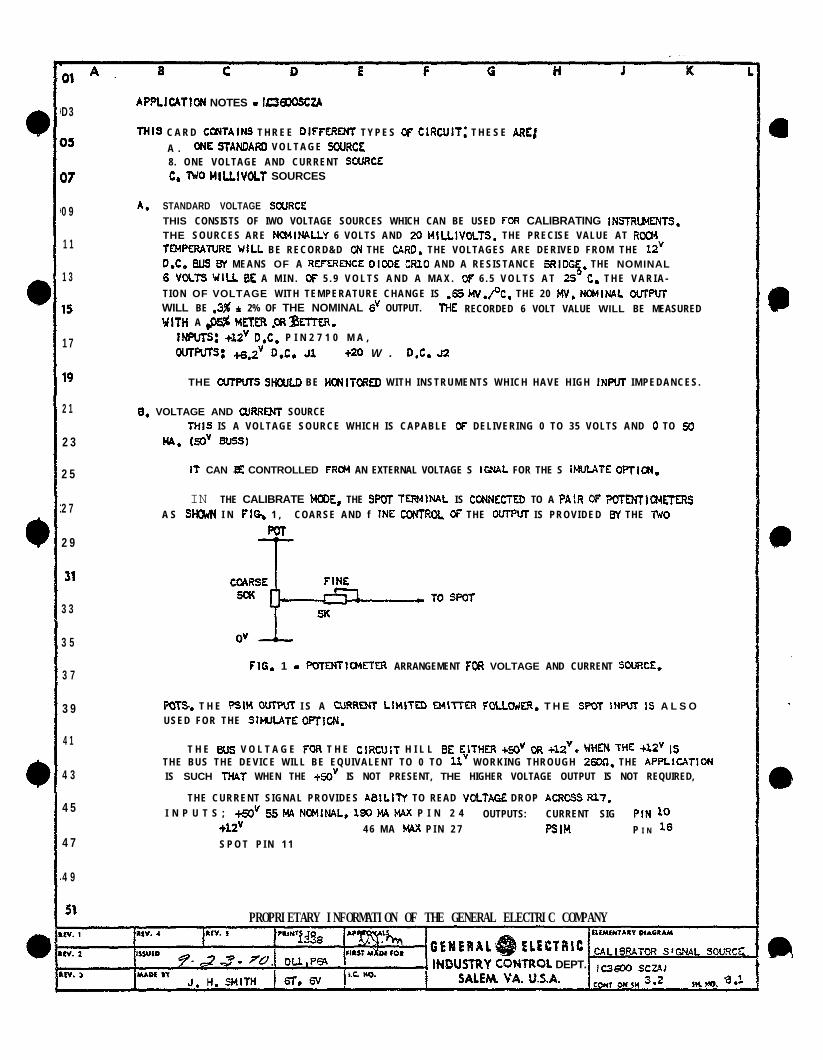
APPLlcATtoN NOTES - 1cmJosczA
THIS C A R D CfflTAtNS T H R E E DIffERENT T Y P E S DF ClRCUit; T H E S E AREJA . CM STAHDARU V O L T A G E SQURCE8. ONE VOLTAGE AND CURRENT SCURCEC. IWO HlLLIVOLT SOURCES
A. STANDARD VOLTAGE SCURCETHIS CONSISTS OF IWO VOLTAGE SOURCES WHICH CAN BE USED FOR CALIBRATING INSTRLMENTS.THE SOURCES ARE NCMINALlY 6 VOLTS AND 20 MiLLlVOLTS. THE PRECISE VALUE AT ROCMTP(PERATURE WILL BE RECORD&D ON THE C4RD. THE VOLTAGES ARE DERIVED FROM THE 12’D.C. BUS By MEANS OF A REfERENCE DIDDE CRT0 AND A RESISTANCE BRIDGE. THE NOMINAL6 VOLTS WILL BE A M I N . DF 5 . 9 V O L T S A N D A M A X . Of 6 . 5 V O L T S A T 25” C. T H E V A R I A -TION OF VOLTAGE WITH TEMPERATURE CHANGE IS .65 MV.,‘?. THE 20 W. WINAL OUTPUTWILL BE .3% 4 2% OF THE NOMINAL 6’ OUTPUT. ME RECORDED 6 VOLT VALUE WILL BE MEASUREDWITH A &5% METER .CRBmER.
fNPUTS: +12’ D.C. P I N 2 7 1 0 M A ,
mRfTs: +& D.C. Jl +20 W . D,C. J2
THE CUTPUTS SHaJLD BE MCNITORED WITH INSTRUMENTS WHICH HAVE HIGH INPUT IMPEDANCES.
0. VOLTAGE AND WRRENT SOURCETHIS IS A VOLTAGE SOURCE WHICH IS CAPABLE Df DELIVERING 0 TO 35 VOLTS AND 0 TO 50
MA, cd Bu5Sl
It CAN a CONTROLLED FRCM AN EXTERNAL VOLTAGE S IGNAt FOR THE S fMULATE OPTICN.
IN THE CALIBRATE MODE, THE SPDT TERMINRL IS CDNNECTED TO A PAlR Df F’OTMTICMETERSA S SHCMN I N FIG, 1 , COARSE AND f INE CoKTROt. CF THE DUTPVT IS PROVIDED By THE nj0
Fm
FIG. 1 - PO-fENTlavlETER ARRANGEMENT FOA VOLTAGE AND CURRENT SDURCE,
PC% T H E QSIM OmPm I S A CURREM LlMiTED B4lTTE.R :QLLCMR. T H E SPOT INPUT US A L S OUSED FOR THE SitMATE OPTION.
T H E BUS V O L T A G E FOR T H E ClRCUlt H I L L 8E EiTHER +SO” CR +IZ’. WHEN WE +12’ ISTHE BUS THE DEVICE WILL BE EQUIVALENT TO 0 TO 11’ WORKING THROUGH 2600, THE APPLlCATlDNIS SUCH THAT’ WHEN THE +SOv IS NOT PRESENT, THE HIGHER VOLTAGE OUTPUT IS NOT REQUIRED,
THE CURRENT SIGNAL PROVIDES ABtLITY TO READ VDLTAGE DROP ACRDSS R17,I N P U T S ; +d 55 t-94 NCWNAL, 190 MA MAX P I N 2 4 OUTPUTS: CURRENT SIG PtN 10
+12V 4 6 M A MAX P I N 2 7 PSIH P I N 16S P O T P I N 1 1
PROPRIETARY INFORMATION OF THE GENERAL ELECTRIC COMPANY
lNDlJSTRY COMTROL DEPT.

01 A
03
D5
37
09
11
13
15
I7
19
21
23
25
!f
29
31
13
I5
17
39
61
13
15
I7
I9
51
8 c D .E F G i i J K
C . WILLWOLT SQURCE ( 2 CfRCUITS P E R C A R D )
ADJUSTABLE FRCM ‘O-60 MILLIVOLT WITH I O+U OU7PW IMPEDANCE, fLaA7lNG WI7H RESPECT
70 THME SYSTM, PROVISlDtd I S M A D E FOR V O L T A G E CoNTROt. ff MIUIVDLT OU7PW fOR SIMULA’IE
OPTION.
THE MILLIVOLT SOURCE DERIVES 17S PckJER FRCM THE iYDT OSCILLATOR. INPUT VOLTAGELFtfEL I S B.4Y; FREQUENCY 3 K H , ME WC; C U R R E N T OWN I S 1SDt.M RMS. T H E A&,VOLTAGE IS RECTIFIED AND flLTERED. A N EMITTER FOLLCWER I S U S E D T O CONlROL THE VccrAGEACROSS A RESISTANCE DIVIDER. . T H E CUTPUT IS A PORTlDN O f THIS DIVIDERS; THE S C PDTINPUT IS CONNECTED To SLIDE OF A 1K FOTENTJMETER WHICH IS CONNECTED BEiWEEN THEi+ AND 0’. I7 PROVIDES THE C O A R S E ADJUSFM&NT of M E pvFM. S C FQT I S ALSO U S E D F O R THEShUtATE CCWRDL, THE SLIDE Of A 1K p07ENTIoMFTER IS CONNECTED TO SfPDTl THE lJDTEN7I~Ei’ERIS CONNECTED BETWEEN 3” AND Ov, 7HIS PROVIDES THE FtNE ADJUSTMEW FOR THE UJTF’UT.
imz 8.4’, 3 K H P I N 32, (46)SW07 P I N 3 5 , (451s e P I N 3 0 , (471
SfPO7 P I N 3 1 , WI
wrpvr: O U T PIN 29,138)3y P I N 2 8 , (36)
CONNECflDN FOR CALIBRATOR IS AS SHCMI BELW:
(361
(38)
(43)
0, FDUR RESISTORS AND A CAP.4ClTM1 ARE MDW7D CN M I S CARD WHICH ARE USED IN CCWUNttiW
WITH T H E CALIB?ATDfI... . . . . l
PROPRIETARY INFORMATION OF THE GENERAL ELEffRlC COMPANY
SALEM, VA. U.S.A.

(27) P12
ICI. - MC 1741 = 7672Pl
Ql - 2N4249 - 68h7355Pl
42 - 2N4899 - 68A772OPl
CR3 4 . N - 56A8202PO52
CR4 - 68hi2SOPl
APPLICATION KOTES
THIS C tRCU tT CONVERTS -50v D .C. TO -12” D. C. 8Y MEANS OF A VOLTAGE CC:iTROLLED SMlNTREGULATOR. A SHUNT TRANS tSTOR IS CONTROLLED BY A VOLTAGE SENSING M ICROELECTRCN tC OPERATIONAL
AWLIFIER. A ZENER SUPPLY CAPABLE OF 60 MA. PROV jOES 5.3’ FOR INTEGRATED C IRCU i is.
INPUTS : + L2’ O.C. PlN 27 70 MA. MAXm 50” D.C. PIN 30 300 MA. MAX
OUTPUTS : -12’ f .I” PIN 29 250 MA. MAX+5.3” i 5% PIN 26 60 MA. MA MAX
REGULAT I ON : -12’ D.C. i .03” FROM 10 I%. TO 250 MA.RIPPLE’. LESS THAN 1CMV P-P ON -12” SUPPLY
THIS CARD b?UST 6E MOUNTED IN THE LAST USAGCE CART) SLOT IN ME CARD ROW OR LEAVE SPACE FOR 2 CARDS
IN THE CARD Rm.
PROPRlETARYlNFORMATfON OFTHE GENERALELECXiC COMPANY
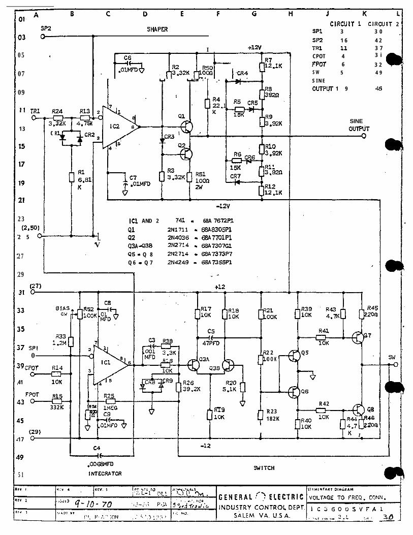
ClRCUlt 1 ClRCUlT 2SPI 3 3 0
SP2 1 6 4 2l-R1 11 3 7
SH4PER
I +12V
. PpCR? y--AZ-05
07
09
11 l-R1cb-
1 3
23(2,501
2 5 o-
27
29
CPOT 4FPOt 6
3 i
3 2S W 5 4 9
S I N E
0UTPtj-r 1 9 4s
KR93.92K
R103.92K
SINEOUTPUT
C Ry-3
I
ICl AND 2 741 - 68A 7672Pl
Ql 2Nl711 - 68A8305Pl42 2N4036 - 63A77olPl
V Q3A 4238 2N27i4 - 68A7307Gl45 - Q 8 2N2714 - 68A7373P7Q 6 - Q 7 2N4249 - 66A7355Pl
(27131-
0
39CPOT RL4
41 1OK
3 3 2 K
45
(29)1 7 0
2 2 Q 5O O K
R 4 2 ;;Iq%R4-l 46
h R 2 31 8 2 K
I Y
4.7jJmQ
K I
$9 L---,-l-.oocz!MFD
5 1 lNTECRA7aRSWITCH

fORM 1C 2 3 9 0 (03-68)
lb1517
19
21
23
25
29
APPLICATION NOTES
F U N C T I O N : T H I S C I R C U I T I S U S E D I N T H E SPEEDTRUNIC CALI5RATOR/SIMULATOR. 1T CAN ACCEPTA V O L T A G E V I A A S I G N A L CONDItlONER C R U S E ITS CklN SWlTCH OUTPUT’ V I A .4N MTL%tAL POTENTIOMEJ’ER
TO CONTROL A FIXED MAGNITUDE VARlABLE FREQUENCY SINE WAVE OaPUl.. THE SINE WAVE IS USED TOSMUtATE THE OUTPUT OF A MAGNETIC PICKUP WHICH IS THE SPEED SIGNAL FOR THE TURBlNE SH4FT.
WHEN USED IN THE CALIBRATOR THE OUTPUI- FREQUENCY IS CONTROLLED BY A f’DTENTIC+tETERf WHENUSED 1N THE SIMULATOR -I% OUT FREQUENCY IS CONTROLLED BY A D.C. VOLTAGE VIA A SIGNALCONDITIONER,
C I R C U I T D E S C R I P T I O N :
THE ClRCUlT CAN BE BROKEN DOW INTO FOUR PART-S:
1. I MEGRATOR2 , S W I T C H - H Y S T E R E S I S3 . SHAPER4. SIGNAL CONDITIONER
INTEGRATOR
4SIGNAL
CDND- . .
JTIONER HYSTERESIS
ISWITCH
! SW. IF I G . I - BLOCK DIAGRAM
THE INTEGRATOR IS A MICROELECTRONIC OPERATIONAL AMPLIFIER. IT WILL INTEGRATE ITS INIjVT U N T I L
THE OUTPUT CAUSES THE HYSTERESIS SWITCH TO OPERATE. A T T H I S T I M E T H E I N T E G R A T O R I N P U T WItLREVERSE POLARITY AND BEGIN INTEGRATING IN THE OPPOSITE DIRECTION UNTIL THE HYSTERESfS SWfTCH
I S S W I T C H E D BACK T O I T S ORIGiNAL C O N D I T I O N , THE RESULT IS THE GENERATION OF A TRIANG?JLAR
W A V E A T T H E lNTECRATOR O U T P U T . THE FREGUENCY IS CONTROLLED BY VARYING THE M4CNlTUDE CF THE
C U R R E N T 1 M O T H E INTEGRATOR I N P U T , T H I S I S D O N E B Y M W N S Gf A POTENT1OMEI.ER I N TilE SIdiTCH
OUTPUT OR 6-f MEANS OF AN EXTERNAL CURRENT SOURCE FED THRU A PA IR OF DIODE SWITCHES WHICHARE CONTROLLED BY THE HYSTERESIS SWITCH OUTPUT.
THE INTEGRATOR OUTPUT IS FED iNT0 A SHAPER WHICH IS AN oPER4TIONAL AMPLIFIER WITH VARIABLE
CAIN. THE GAIN IS REDUCED AT THREE DISTINCT LEVELS. TWO A R E A T T A I N E D 8Y V A R Y I N G T H E FEEDE4CK
R E S I S T A N C E T H E O T H E R By V A R Y I N G T H E I N P U T R E S I S T A N C E . T H E R E S U L T O F T H E S E G4lN CWNGES I S A
ROUNDING OF THE TRIANGLE WAVE F&M AND A STEEPENING OF THE ZERO CROSSOVERS TO Al- i -A IN A SINEWAVE.
C I R C U I T CwRACTERfSTICS:
1. POdER I N P U T +12v 1cy~ bt4 W I T H lOOn L O A D
-12Y 100 :t4 W I T H lo0t-l L O A D
2 . S I G N A L I N P U T : V I A POTENTlCMETER O R D I O D E S W I T C H E S O-+1,0 t-t4 V A R I E S T H E F R E Q U E N N Fi?CM
0 TO APPROX . 12 KHZ.
PROPPJETARY iNFOR!~lAT:OM QF THE GENERAL ELECTRJC COMPANY

._.___. -___- _.__ “._.I ..__ __- ^____ --_ .-.~ ___._ _-. _--. _ - _ --. _-_ . -- _....- -
09
23
25
29
3 1
33
3. SINE WAVE CUTPUT:
VOLTAGE - 1OV P - P O R 3.53 m. .CURRENT - 1 4 0 MA P - P O R 4 9 . 5 MA RMS
(WITHOUT CHANGE IN OUTPUT VOLTAGE LEVEL)fREQUENCY-CONTINUOUSLY VARlABLE F R O M 0 T O 1 2 K H Z
LOWEST USEASLE FREQUENCY - 15 HZ.
CALI BRATOR HCQKUP:
f POTI C36CQSVfAl
4 t31) C POTr-n3 ( 3 0 91
10KF
PROPRIETARY INFORMATIO~I OF THE GEHERAl ELECTRIC fOMPANYtv t s-r/e<*/ IllMtNTAPI DIAbRIM
//-rl.l ,
!V. t VOLTAGE TO fRE(?UEt’ICY CCr!‘i
iv. 1 MADf YY4 fi 1338 “’ ‘* SALEM. VA. U.S.A.
, C 3 6 o o S V f A 1
LX PE”sRSON l-ON1 ON 1* FL. J,‘ NO 3 .2
A B C D
Dl
33
D7
39
I1
13
15
I7
I9
21
23
25
17
29
31
3 3
35
3 7
3 9
11
43
45
4 7
I9
51
NU’IES -
1 CURRENT MAY HE MEASURE,,B Y IN,4 F R O M U2 !*) T Oc2 I-), 1 MA - lcw
2 . SWITCH ~~SW)~~ W I L LCONNECT E ITHER MVSOURCE TO EITHER PATCH
PJINT
S W D3WN - M”A T O NV1MVB T O MV2
SW. UP M V A T O MV2MVS T O MVl
3 . CONNECT’33 P I N N O ’ SARE SHOWN IN LOWERLEFT OF EACH BLC)CK
4 MARK 1 HAS BOTH PSOVAND N!iOV BUT MARK I I
HAS ONLY PSV IN PLACEO F T H E S E T W O . (-1
INTERCONNECTION TO PAGE MADE THRaUGH CONNECTORS _
a . . I 0 . ,oI 0 a 017 19 49 IS1 IS 20 1 3 4 , 3 2
I I I IMI LLVOLT SOURCES SE%&
0 0 0t+, MVA (-)
.(t, M E! :I
. . 0#t
22 I II I
0 0 0 0 0 0 . 0(CCNN “8”
4 5 ,s 7 5 9 IO 23I I I I
- A C O M -. . 0’ 0 l 0 0 l
(*NnLoo COMMON)
H l . . . . . . �. . .
21 � I I II 12 1 3 14 15 ISI I I I I
0 0I 4s l ☯ 48. 1 3; c
2 44
0 0 0 0 l D4 4s 47 4 9 32
I
. 0 0 0 l E9 27 ,z* 33 1 4I
. 0 . 0 l F3 1s , 17 13 ,9
8 I
0 0 0 . 0’ G4 5 6 7
II I
P l /,8o !/ (,, . !*T /�
1 9 g21
23
A B C D E F G H J K 1 M N P Q R S T U V 16 Iii 1


‘DRIVE SYSTEMS PRODUCT DEPARTMENTSALEM, VA. 24153
GENERAL@!) E L E C T R I C
8-78 (1M)