Embed Size (px)
Citation preview

GEMÜ 567 BioStar controlservoDrive
Aseptic control valve with motorized eSyDrive/servoDrive actuator
Operating instructionsEN
further informationwebcode: GW-567

All rights including copyrights or industrial property rights are expressly reserved.
Keep the document for future reference.
© GEMÜ Gebr. Müller Apparatebau GmbH & Co. KG17.07.2019
www.gemu-group.com2 / 48GEMÜ 567
servoDrive
Contents1 General information ................................................... 4
1.1 Information ......................................................... 41.2 Symbols used ..................................................... 41.3 Definition of terms ............................................. 41.4 Warning notes .................................................... 4
2 Safety information .................................................... 53 Product description ................................................... 54 Correct use ................................................................ 65 Order data - servoDrive ............................................. 86 Technical data ........................................................... 117 Dimensions ............................................................... 158 Manufacturer's information ....................................... 30
8.1 Delivery ............................................................... 308.2 Packaging ........................................................... 308.3 Transport ............................................................ 308.4 Storage ............................................................... 30
9 Installation in piping .................................................. 309.1 Installation location ........................................... 309.2 Preparing for installation ................................... 309.3 Installation with clamp connections ................. 319.4 Installation with butt weld spigots .................... 31
10 Mounting .................................................................. 3211 Electrical connection ................................................. 3413 Error clearance .......................................................... 3514 Inspection/maintenance ............................................ 3615 Removal from piping ................................................. 4516 Disposal .................................................................... 4517 Returns ..................................................................... 4518 Declaration of Incorporation according to 2006/42/
EC (Machinery Directive) ........................................... 4619 Declaration of conformity according to 2014/30/EU
(EMC Directive) ......................................................... 47
GEMÜ 567
servoDrive
www.gemu-group.com 3 / 48

www.gemu-group.com4 / 48GEMÜ 567
servoDrive
1 General information
1 General information
1.1 Information
– The descriptions and instructions apply to the stand-ard versions. For special versions not described in thisdocument the basic information contained herein ap-plies in combination with any additional special docu-mentation.
– Correct installation, operation, maintenance and repairwork ensure faultless operation of the product.
– Should there be any doubts or misunderstandings, theGerman version is the authoritative document.
– Contact us at the address on the last page for stafftraining information.
1.2 Symbols used
The following symbols are used in this document:
Symbol MeaningTasks to be performedResponse(s) to tasks
– Lists
1.3 Definition of terms
Working mediumThe medium that flows through the GEMÜ product.PDPD = Plug Diaphragm
1.4 Warning notes
Wherever possible, warning notes are organised according tothe following scheme:
SIGNAL WORD
Type and source of the dangerPossiblesymbol for thespecificdanger
Possible consequences of non-observance.
Measures for avoiding danger.
Warning notes are always marked with a signal word andsometimes also with a symbol for the specific danger.The following signal words and danger levels are used:
DANGERImminent danger!▶ Non-observance can cause death or
severe injury.
WARNINGPotentially dangerous situation!▶ Non-observance can cause death or
severe injury.
CAUTIONPotentially dangerous situation!▶ Non-observance can cause moderate
to light injury.
NOTICEPotentially dangerous situation!▶ Non-observance can cause damage to
property.
The following symbols for the specific dangers can be usedwithin a warning note:
Symbol MeaningDanger of explosion
Corrosive chemicals
Hot plant components!
Danger - high voltage!

www.gemu-group.com 5 / 48 GEMÜ 567
servoDrive
2 Safety informationThe safety information in this document refers only to an in-dividual product. Potentially dangerous conditions can arisein combination with other plant components, which need tobe considered on the basis of a risk analysis. The operator isresponsible for the production of the risk analysis and forcompliance with the resulting precautionary measures andregional safety regulations.The document contains fundamental safety information thatmust be observed during commissioning, operation andmaintenance. Non-compliance with these instructions maycause:– Personal hazard due to electrical, mechanical and
chemical effects.– Hazard to nearby equipment.– Failure of important functions.– Hazard to the environment due to the leakage of dan-
gerous materials.The safety information does not take into account:– Unexpected incidents and events, which may occur
during installation, operation and maintenance.– Local safety regulations which must be adhered to by
the operator and by any additional installation person-nel.
Prior to commissioning:1. Transport and store the product correctly.2. Do not paint the bolts and plastic parts of the product.3. Carry out installation and commissioning using trained
personnel.4. Provide adequate training for installation and operating
personnel.5. Ensure that the contents of the document have been fully
understood by the responsible personnel.6. Define the areas of responsibility.7. Observe the safety data sheets.8. Observe the safety regulations for the media used.
During operation:9. Keep this document available at the place of use.10. Observe the safety information.11. Operate the product in accordance with this document.12. Operate the product in accordance with the specifica-
tions.13. Maintain the product correctly.14. Do not carry out any maintenance work and repairs not
described in this document without consulting the manu-facturer first.
In cases of uncertainty:15. Consult the nearest GEMÜ sales office.
3 Product description
3.1 Construction
1
2
4
5
6
3
Item Name Materials1 Electrical connections2 Connection cable PUR3 Cable gland Stainless steel4 Actuator housing 1.43055 Distance piece with leak detection
hole1.4404
6 Valve body 1.4435
3.2 Function
The product is a motorized 2/2-way diaphragm globe valvemade of stainless steel. The GEMÜ 567 2/2-way diaphragmglobe valve is designed for installation in piping systems andhas been equipped with a GEMÜ PD design. Flow rates ofbetween 80 l/h and 4100 l/h are possible, depending on theversion.An external controller is required to operate the valve. Thevalve does not work without a controller.With this external controller, the filling valve offers flexibleand fast program changes thanks to freely programmablefilling curves.The external controller is not included in the scope of deliv-ery.
3 Product description

www.gemu-group.com6 / 48GEMÜ 567
servoDrive
4 Correct use
3.3 PD seal system
1
2
3
4
Item PTFE plug diaphragm (actuator seal)1 O-ring (seat seal) FPM2 Regulating cone stainless steel (1.4435)3 Support ring stainless steel (1.4435)4 Plug diaphragm (actuator seal) PTFE
1
2
3
4
5
Item PTFE plug diaphragm (actuator seal)1 O-ring (seat seal) FPM2 Regulating cone stainless steel (1.4435)3 Support ring stainless steel (1.4435)4 Plug diaphragm (actuator seal) PTFE5 Bypass diaphragm
1
Special function M - 3A
3.4 Flow direction
3.4.1 Installation position for optimized draining
in open and closed position in open position
3.5 Description
The GEMÜ 567 2/2-way diaphragm globe valve is motorized.The product can be operated with the servoDrive actuator.The servoDrive actuator can be used for extremely preciseand fast control and filling processes in aseptic and hygienicareas of application.
4 Correct use
DANGERDanger of explosion▶ Risk of death or severe injury.● Do not use the product in potentially
explosive zones.
WARNINGImproper use of the product!▶ Risk of severe injury or death.▶ Manufacturer liability and guarantee will be void.● Only use the product in accordance with the operating
conditions specified in the contract documentation andthis document.
The product is designed for installation in piping systemsand for controlling a working medium.The product is not intended for use in potentially explosiveareas.
● Use the product in accordance with the technical data.

4 Correct use
www.gemu-group.com 7 / 48 GEMÜ 567
servoDrive

5 Order data - servoDriveThe order data provide an overview of standard configurations.
Please check the availability before ordering. Other configurations available on request.
Order codes
1 Type CodeControl valve 567
2 DN CodeDN 8 8DN 10 10DN 20 20
3 Body configuration Code2-way angle body E2-way angle body with bypass M
4 Connection type CodeSpigotSpigot DIN 0Spigot EN 10357 series A (formerly DIN 11850series 2) / DIN 11866 series A
17
Spigot ASME BPE / DIN 11866 series C 59Spigot ISO 1127 / EN 10357 series C / DIN 11866series B
60
ClampClamp DIN 32676 series B 82Clamp DIN 32676 series A 86Clamp ASME BPE 88
5 Valve body material Code1.4435 (316L), block material 411.4435 (BN2), block material, Δ Fe<0.5% 43
6 Seal material CodeActuator seal PTFE/seat seal FPMFPM
4
Actuator seal PTFE/seat seal PTFE,PTFE
5
Actuator seal PTFE/seat seal FPM,FPM
43
Actuator seal PTFE/seat seal FPM,PTFE/FPM
45
Actuator seal PTFE/seat seal FPM,FPM
47
Actuator seal PTFE/seat seal PTFE,PTFE/EPDM
55
7 Voltage / Frequency Code48 V DC D1
8 Control module CodeOPEN/CLOSE, positioner and process controller L0
9 Cable length Code0.5 m 01.0 m 12.0 m 2
9 Cable length Code3.0 m 3
10 Control characteristic Codemodified equal-percentage Glinear L
11 Kv value Code80 l/h AA100 l/h AB160 l/h BC250 l/h BD400 l/h BE630 l/h CF1.0 m³/h CG1.6 m³/h DH2.6 m³/h EJ4.1 m³/h G1
12 Bypass actuator version CodeActuator size 11 11Actuator size S0 S0
13 Actuator+interface CodeServoDrive with standard bus TNServoDrive with Powerlink TP
14 Special version CodeSpecial version for 3A M
15 Surface CodeRa ≤ 0.25 µm (10 µin.) for media wetted surfaces*),in accordance with DIN 11866 HE5,electropolished internal/external,*) for inner pipe diameter < 6 mm, in spigots Ra ≤0.38 µm
1516
Ra ≤ 0.25 µm (10 µin.) for media wetted surfaces*),in accordance with DIN 11866 H5,mechanically polished internal,*) for inner pipe diameter < 6 mm, in spigots Ra ≤0.38 µm
1527
Ra ≤ 0.4 µm (15 µin.) for media wetted surfaces,in accordance with DIN 11866 H4,mechanically polished internal
1536
Ra ≤ 0.4 µm (15 µin.) for media wetted surfaces,in accordance with DIN 11866 HE4,electropolished internal/external
1537
Ra max. 0.51 µm (20 µin.) for media wettedsurfaces,in accordance with ASME BPE SF1,mechanically polished internal
SF1
5 Order data - servoDrive
www.gemu-group.com8 / 48GEMÜ 567
servoDrive
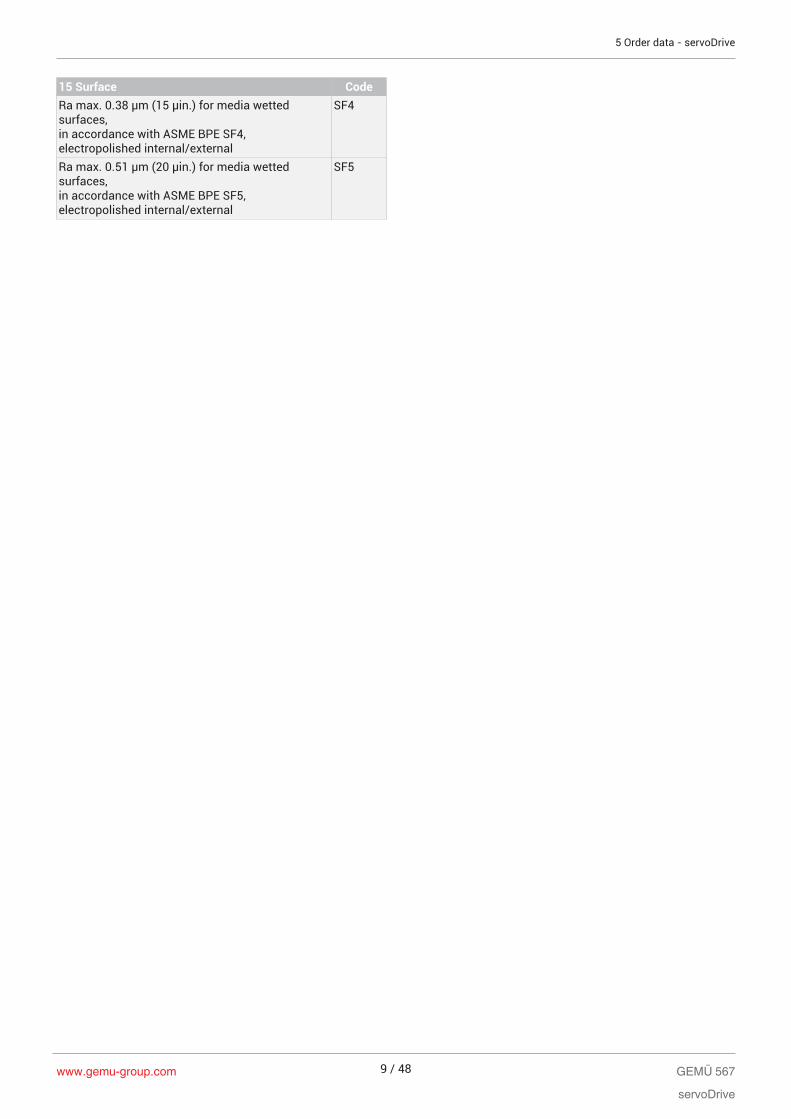
15 Surface CodeRa max. 0.38 µm (15 µin.) for media wettedsurfaces,in accordance with ASME BPE SF4,electropolished internal/external
SF4
Ra max. 0.51 µm (20 µin.) for media wettedsurfaces,in accordance with ASME BPE SF5,electropolished internal/external
SF5
5 Order data - servoDrive
www.gemu-group.com 9 / 48 GEMÜ 567
servoDrive
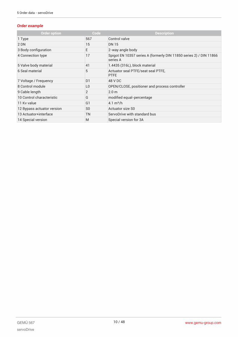
Order example
Order option Code Description1 Type 567 Control valve2 DN 15 DN 153 Body configuration E 2-way angle body4 Connection type 17 Spigot EN 10357 series A (formerly DIN 11850 series 2) / DIN 11866
series A5 Valve body material 41 1.4435 (316L), block material6 Seal material 5 Actuator seal PTFE/seat seal PTFE,
PTFE7 Voltage / Frequency D1 48 V DC8 Control module L0 OPEN/CLOSE, positioner and process controller9 Cable length 2 2.0 m10 Control characteristic G modified equal-percentage11 Kv value G1 4.1 m³/h12 Bypass actuator version S0 Actuator size S013 Actuator+interface TN ServoDrive with standard bus14 Special version M Special version for 3A
5 Order data - servoDrive
www.gemu-group.com10 / 48GEMÜ 567
servoDrive

6 Technical data
6.1 Medium
Working medium: Corrosive, inert, gaseous and liquid media which have no negative impact on the physical andchemical properties of the body and diaphragm material.
6.2 Temperature
Media temperature: Without bypass -10 to 160 °CWith bypass -10 to 100 °C
Sterilisation temperature: Seat seal FPM without bypass, (code 4) 160 °C 1), steam max. 30 min 2)
Seat seal PTFE without bypass, (code 5) 160 °C 1), steam max. 30 min 2)
Seat seal FPMbypass diaphragm material EPDM,(code 43)
150 °C 3), max. 30 min
Seat seal FPM bypass diaphragm material PTFE/EPDM,PTFE laminated, (code 45)
150 °C 3), max. 30 min
Seat seal FPMbypass diaphragm material EPDM,(code 47)
150 °C 3), max. 30 min
Seat seal PTFE bypass diaphragm material PTFE/EPDM,PTFE laminated, (code 55)
150 °C 3), max. 30 min
1) The sterilisation temperature is only valid for steam (saturated steam) or superheated water.
2) Longer sterilisation times or continuous operation on request
3) If the sterilisation temperatures listed above are applied to the EPDM diaphragms for longer periods oftime, the service life of the diaphragms will be reduced. In these cases, maintenance cycles must be adap-ted accordingly. This also applies to PTFE diaphragms exposed to high temperature fluctuations. Themaintenance cycles must be adapted accordingly.
Ambient temperature: -10 to 60 °C
Storage temperature: 0 to 40 °C
6.3 Pressure
Operating pressure: -10 to 130 °C 0 to 10 bar
Pressure/Temperature diagram11
10
9
8
7
6
5
4
3
2
1
-20 -10 0 20 40 60 80 100 120 140 160130
Temperature [°C]
Ope
ratin
g pr
essu
re [b
ar]
GEMÜ 567
servoDrive
www.gemu-group.com 11 / 48
6 Technical data

Kv values: 100
80
60
40
20
100806040200
L
G
0
Kv v
alue
[%]
Stroke [%]
Equal-percentage (except code 59) / linear (except code 59)
Control charac-teristic
Kv value DN 8 DN 10 DN 15
GAA, LAA 80 l/h X X XGAB, LAB 100 l/h X X XGBC, LBC 160 l/h X X XGBD, LBD 250 l/h X X XGBE, LBE 400 l/h X X XGCF, LCF 630 l/h X X XGCG, LCG 1.0 m³/h - X XGDH, LDH 1.6 m³/h - X XGEJ, LEJ 2.6 m³/h - - XGG1, LG1 4.1 m³/h - - X
Equal-percentage (only code 59) / linear (only code 59)
Control characteristic Kv value DN 15 DN 20GAA, LAA 80 l/h X XGAB, LAB 100 l/h X XGBC, LBC 160 l/h X XGBD, LBD 250 l/h X XGBE, LBE 400 l/h X XGCF, LCF 630 l/h X XGCG, LCG 1.0 m³/h X XGDH, LDH 1.6 m³/h X XGEJ, LEJ 2.6 m³/h - XGG1, LG1 4.1 m³/h - X
www.gemu-group.com12 / 48GEMÜ 567
servoDrive
6 Technical data

6.4 Product compliance
Machinery Directive: 2006/42/EU
EMC Directive: 2014/30/EU
Foodstuffs: FDAUSP Class VIEC regulation 1935/2004EC regulation 10/2011
6.5 Mechanical data
Protection class: Actuator and cable exit: IP69K acc. to EN 60529Connector plug: IP65/IP67 acc. to EN 60529 when plugged inIP 65 acc. to EN 60529
Weight: Actuator servoDrive 1.3 kg + kg adaptor
Operating time: servoDrive actuator adjustable, max. 200 mm/s
6.6 Electrical data - servoDrive
Humidity: Relative humidity: 5–95%Absolute humidity: 1–29 g/m³
6.6.1 Supply voltage
Actuator voltage: 48 V DC ± 10%
Logic voltage (simcodrive controller):
24 V DC ± 10%
Maximum current: 6.7 A
Extended standstillcurrent:
2 A
Rated current: 1.8 A
Maximum power: 150 W
Rated power: ≤ 55 W
Duty cycle: 100%
Reverse batteryprotection:
Yes
6.6.2 Electrical connection
Connection: Connection cable with connector
Connector plug: Intercontec series 915 12 + 3-pin
Plug cycles: <500
6.6.3 Connection cable
Cable length: 3 m (extension cable 5 m)
Cable material: PUR
Shield: Twofold shield
Cable colour: Black
GEMÜ 567
servoDrive
www.gemu-group.com 13 / 48
6 Technical data

Bend radius: Single movement ≥ 3 x DMoving ≥ 10 x D
Drag chain data: Acceleration 2 m/s²Bend cycles 1,000,000Speed 3 m/s
Resistance: Oil resistance in accordance with EN 60811-404
Torsion applications: Not suitable
Approval: UL AWM Style 20233, 80 °C, 300 V
www.gemu-group.com14 / 48GEMÜ 567
servoDrive
6 Technical data

7 Dimensions
7.1 Actuator dimensions
7.1.1 servoDrive
A
CT
*
øB
DN Actuatorsize
A øB
8, 10, 15, 20 2 245 40
Dimensions in mm* CT = A + H1 (see body dimensions)
GEMÜ 567
servoDrive
www.gemu-group.com 15 / 48
7 Dimensions
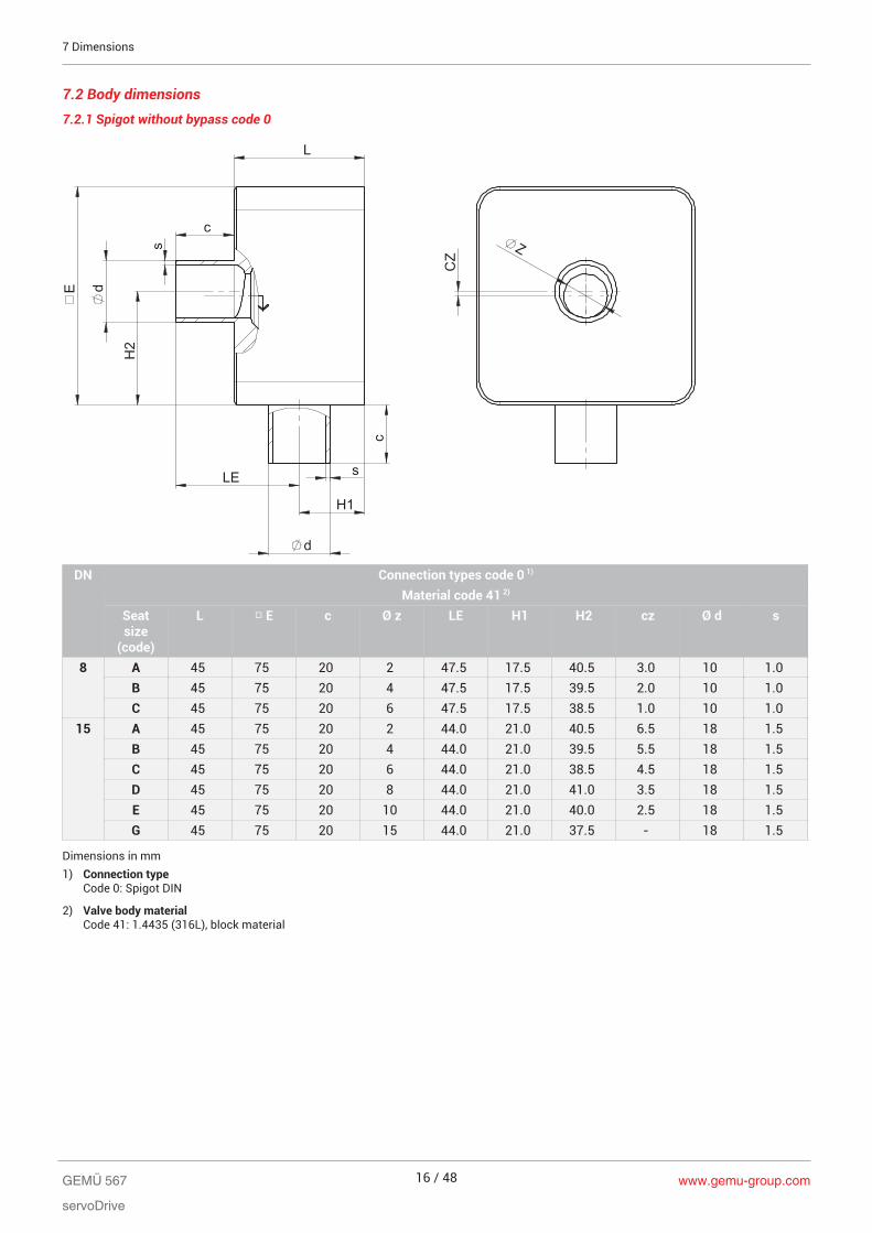
7.2 Body dimensions
7.2.1 Spigot without bypass code 0 H
2
E
L
c
c
s
d
s
d
LE
H1
CZ
Z
DN Connection types code 0 1)
Material code 41 2)
Seatsize
(code)
L □ E c Ø z LE H1 H2 cz Ø d s
8 A 45 75 20 2 47.5 17.5 40.5 3.0 10 1.0B 45 75 20 4 47.5 17.5 39.5 2.0 10 1.0C 45 75 20 6 47.5 17.5 38.5 1.0 10 1.0
15 A 45 75 20 2 44.0 21.0 40.5 6.5 18 1.5B 45 75 20 4 44.0 21.0 39.5 5.5 18 1.5C 45 75 20 6 44.0 21.0 38.5 4.5 18 1.5D 45 75 20 8 44.0 21.0 41.0 3.5 18 1.5E 45 75 20 10 44.0 21.0 40.0 2.5 18 1.5G 45 75 20 15 44.0 21.0 37.5 - 18 1.5
Dimensions in mm1) Connection type
Code 0: Spigot DIN
2) Valve body materialCode 41: 1.4435 (316L), block material
www.gemu-group.com16 / 48GEMÜ 567
servoDrive
7 Dimensions
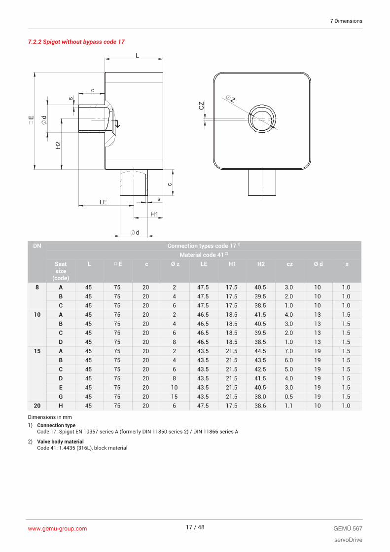
7.2.2 Spigot without bypass code 17
H2
E
L
c
c
s
d
s
d
LE
H1
CZ
Z
DN Connection types code 17 1)
Material code 41 2)
Seatsize
(code)
L □ E c Ø z LE H1 H2 cz Ø d s
8 A 45 75 20 2 47.5 17.5 40.5 3.0 10 1.0B 45 75 20 4 47.5 17.5 39.5 2.0 10 1.0C 45 75 20 6 47.5 17.5 38.5 1.0 10 1.0
10 A 45 75 20 2 46.5 18.5 41.5 4.0 13 1.5B 45 75 20 4 46.5 18.5 40.5 3.0 13 1.5C 45 75 20 6 46.5 18.5 39.5 2.0 13 1.5D 45 75 20 8 46.5 18.5 38.5 1.0 13 1.5
15 A 45 75 20 2 43.5 21.5 44.5 7.0 19 1.5B 45 75 20 4 43.5 21.5 43.5 6.0 19 1.5C 45 75 20 6 43.5 21.5 42.5 5.0 19 1.5D 45 75 20 8 43.5 21.5 41.5 4.0 19 1.5E 45 75 20 10 43.5 21.5 40.5 3.0 19 1.5G 45 75 20 15 43.5 21.5 38.0 0.5 19 1.5
20 H 45 75 20 6 47.5 17.5 38.6 1.1 10 1.0
Dimensions in mm1) Connection type
Code 17: Spigot EN 10357 series A (formerly DIN 11850 series 2) / DIN 11866 series A
2) Valve body materialCode 41: 1.4435 (316L), block material
GEMÜ 567
servoDrive
www.gemu-group.com 17 / 48
7 Dimensions
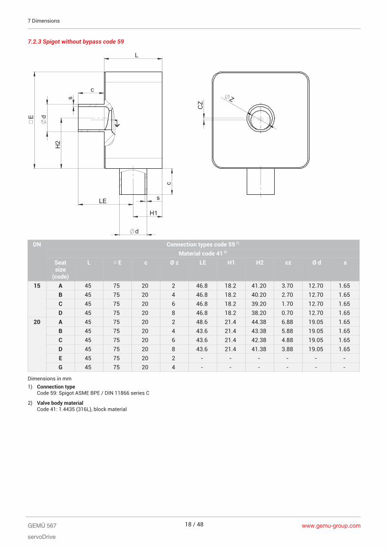
7.2.3 Spigot without bypass code 59
H2
E
L
c
c
s
d
s
d
LE
H1
CZ
Z
DN Connection types code 59 1)
Material code 41 2)
Seatsize
(code)
L □ E c Ø z LE H1 H2 cz Ø d s
15 A 45 75 20 2 46.8 18.2 41.20 3.70 12.70 1.65B 45 75 20 4 46.8 18.2 40.20 2.70 12.70 1.65C 45 75 20 6 46.8 18.2 39.20 1.70 12.70 1.65D 45 75 20 8 46.8 18.2 38.20 0.70 12.70 1.65
20 A 45 75 20 2 48.6 21.4 44.38 6.88 19.05 1.65B 45 75 20 4 43.6 21.4 43.38 5.88 19.05 1.65C 45 75 20 6 43.6 21.4 42.38 4.88 19.05 1.65D 45 75 20 8 43.6 21.4 41.38 3.88 19.05 1.65E 45 75 20 2 - - - - - -G 45 75 20 4 - - - - - -
Dimensions in mm1) Connection type
Code 59: Spigot ASME BPE / DIN 11866 series C
2) Valve body materialCode 41: 1.4435 (316L), block material
www.gemu-group.com18 / 48GEMÜ 567
servoDrive
7 Dimensions
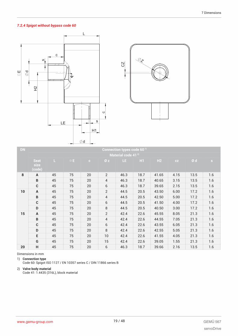
7.2.4 Spigot without bypass code 60
H2
E
L
c
c
s
d
s
d
LE
H1
CZ
Z
DN Connection types code 60 1)
Material code 41 2)
Seatsize
(code)
L □ E c Ø z LE H1 H2 cz Ø d s
8 A 45 75 20 2 46.3 18.7 41.65 4.15 13.5 1.6B 45 75 20 4 46.3 18.7 40.65 3.15 13.5 1.6C 45 75 20 6 46.3 18.7 39.65 2.15 13.5 1.6
10 A 45 75 20 2 44.5 20.5 43.50 6.00 17.2 1.6B 45 75 20 4 44.5 20.5 42.50 5.00 17.2 1.6C 45 75 20 6 44.5 20.5 41.50 4.00 17.2 1.6D 45 75 20 8 44.5 20.5 40.50 3.00 17.2 1.6
15 A 45 75 20 2 42.4 22.6 45.55 8.05 21.3 1.6B 45 75 20 4 42.4 22.6 44.55 7.05 21.3 1.6C 45 75 20 6 42.4 22.6 43.55 6.05 21.3 1.6D 45 75 20 8 42.4 22.6 42.55 5.05 21.3 1.6E 45 75 20 10 42.4 22.6 41.55 4.05 21.3 1.6G 45 75 20 15 42.4 22.6 39.05 1.55 21.3 1.6
20 H 45 75 20 6 46.3 18.7 39.66 2.16 13.5 1.6
Dimensions in mm1) Connection type
Code 60: Spigot ISO 1127 / EN 10357 series C / DIN 11866 series B
2) Valve body materialCode 41: 1.4435 (316L), block material
GEMÜ 567
servoDrive
www.gemu-group.com 19 / 48
7 Dimensions
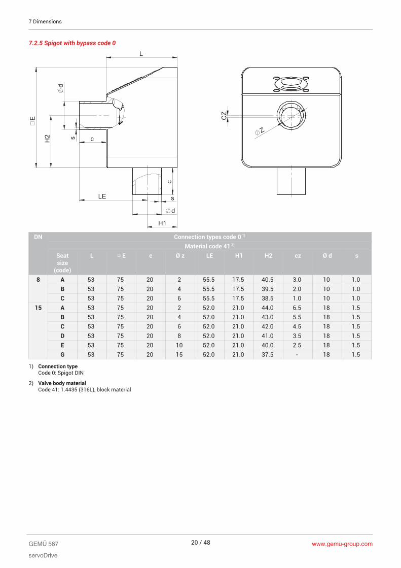
7.2.5 Spigot with bypass code 0
s
d
c
c s
d
LE
E
H2
L
H1 C
Z
Z
DN Connection types code 0 1)
Material code 41 2)
Seatsize
(code)
L □ E c Ø z LE H1 H2 cz Ø d s
8 A 53 75 20 2 55.5 17.5 40.5 3.0 10 1.0B 53 75 20 4 55.5 17.5 39.5 2.0 10 1.0C 53 75 20 6 55.5 17.5 38.5 1.0 10 1.0
15 A 53 75 20 2 52.0 21.0 44.0 6.5 18 1.5B 53 75 20 4 52.0 21.0 43.0 5.5 18 1.5C 53 75 20 6 52.0 21.0 42.0 4.5 18 1.5D 53 75 20 8 52.0 21.0 41.0 3.5 18 1.5E 53 75 20 10 52.0 21.0 40.0 2.5 18 1.5G 53 75 20 15 52.0 21.0 37.5 - 18 1.5
1) Connection typeCode 0: Spigot DIN
2) Valve body materialCode 41: 1.4435 (316L), block material
www.gemu-group.com20 / 48GEMÜ 567
servoDrive
7 Dimensions
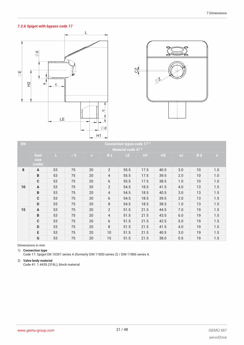
7.2.6 Spigot with bypass code 17
s
d
c
c s
d
LE
E
H2
L
H1 C
Z
Z
DN Connection types code 17 1)
Material code 41 2)
Seatsize
(code)
L □ E c Ø z LE H1 H2 cz Ø d s
8 A 53 75 20 2 55.5 17.5 40.5 3.0 10 1.0B 53 75 20 4 55.5 17.5 39.5 2.0 10 1.0C 53 75 20 6 55.5 17.5 38.5 1.0 10 1.0
10 A 53 75 20 2 54.5 18.5 41.5 4.0 13 1.5B 53 75 20 4 54.5 18.5 40.5 3.0 13 1.5C 53 75 20 6 54.5 18.5 39.5 2.0 13 1.5D 53 75 20 8 54.5 18.5 38.5 1.0 13 1.5
15 A 53 75 20 2 51.5 21.5 44.5 7.0 19 1.5B 53 75 20 4 51.5 21.5 43.5 6.0 19 1.5C 53 75 20 6 51.5 21.5 42.5 5.0 19 1.5D 53 75 20 8 51.5 21.5 41.5 4.0 19 1.5E 53 75 20 10 51.5 21.5 40.5 3.0 19 1.5G 53 75 20 15 51.5 21.5 38.0 0.5 19 1.5
Dimensions in mm1) Connection type
Code 17: Spigot EN 10357 series A (formerly DIN 11850 series 2) / DIN 11866 series A
2) Valve body materialCode 41: 1.4435 (316L), block material
GEMÜ 567
servoDrive
www.gemu-group.com 21 / 48
7 Dimensions
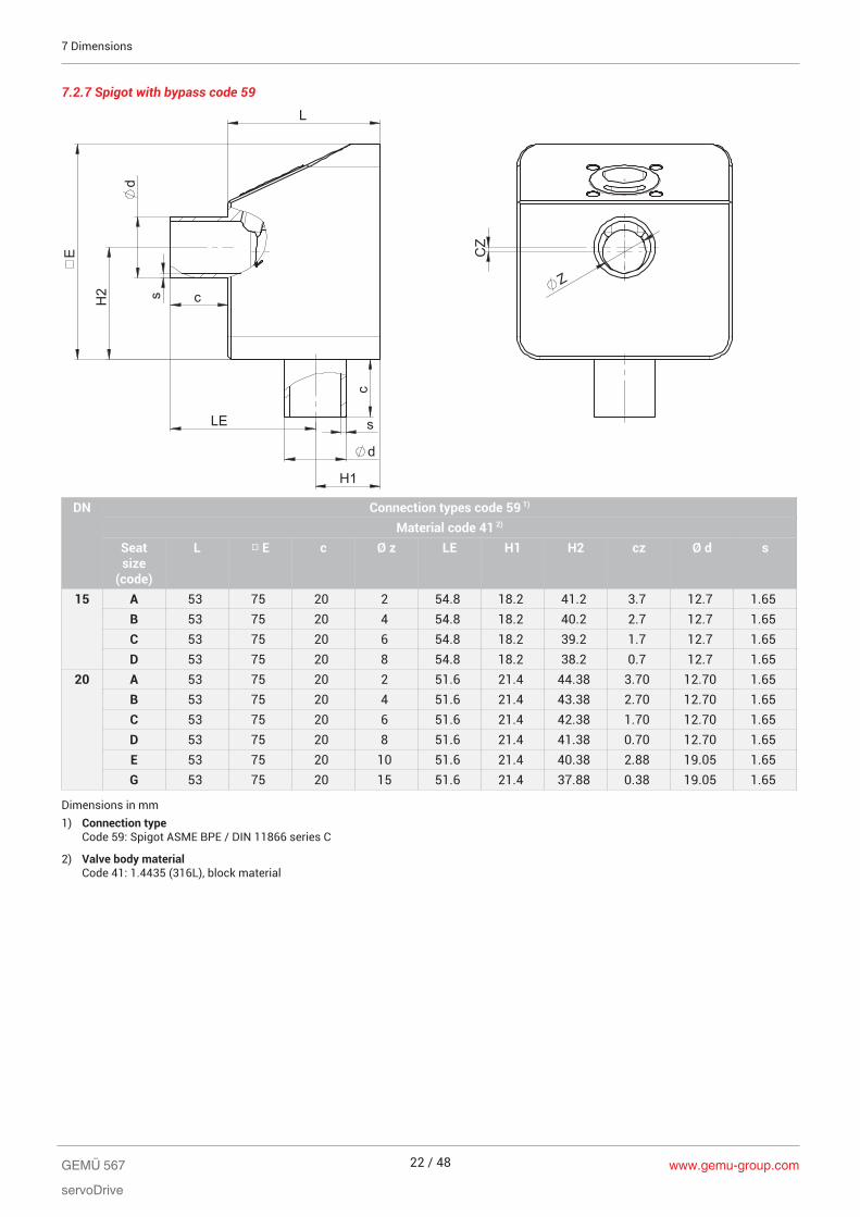
7.2.7 Spigot with bypass code 59
s
d
c
c s
d
LE
E
H2
L
H1 C
Z
Z
DN Connection types code 59 1)
Material code 41 2)
Seatsize
(code)
L □ E c Ø z LE H1 H2 cz Ø d s
15 A 53 75 20 2 54.8 18.2 41.2 3.7 12.7 1.65B 53 75 20 4 54.8 18.2 40.2 2.7 12.7 1.65C 53 75 20 6 54.8 18.2 39.2 1.7 12.7 1.65D 53 75 20 8 54.8 18.2 38.2 0.7 12.7 1.65
20 A 53 75 20 2 51.6 21.4 44.38 3.70 12.70 1.65B 53 75 20 4 51.6 21.4 43.38 2.70 12.70 1.65C 53 75 20 6 51.6 21.4 42.38 1.70 12.70 1.65D 53 75 20 8 51.6 21.4 41.38 0.70 12.70 1.65E 53 75 20 10 51.6 21.4 40.38 2.88 19.05 1.65G 53 75 20 15 51.6 21.4 37.88 0.38 19.05 1.65
Dimensions in mm1) Connection type
Code 59: Spigot ASME BPE / DIN 11866 series C
2) Valve body materialCode 41: 1.4435 (316L), block material
www.gemu-group.com22 / 48GEMÜ 567
servoDrive
7 Dimensions

7.2.8 Spigot with bypass code 60
s
d
c
c s
d
LE
E
H2
L
H1 C
Z
Z
DN Connection types code 60 1)
Material code 41 2)
Seatsize
(code)
L □ E c Ø z LE H1 H2 cz Ø d s
8 A 53 75 20 2 54.3 18.7 41.65 4.15 13.5 1.6B 53 75 20 4 54.3 18.7 40.65 3.15 13.5 1.6C 53 75 20 6 54.3 18.7 39.65 2.15 13.5 1.6
10 A 53 75 20 2 52.5 20.7 43.50 6.00 17.2 1.6B 53 75 20 4 52.5 20.7 42.50 5.00 17.2 1.6C 53 75 20 6 52.5 20.5 41.5 4,00 17.2 1.6D 53 75 20 8 52.5 20.5 40.5 3,00 17.2 1.6
15 A 53 75 20 2 50.4 22.6 45.55 8.05 21.3 1.6B 53 75 20 4 50.4 22.6 44.55 7.05 21.3 1.6C 53 75 20 6 50.4 22.6 43.55 6.05 21.3 1.6D 53 75 20 8 50.4 22.6 42.55 5.05 21.3 1.6E 53 75 20 10 50.4 22.6 41.55 4.05 21.3 1.6G 53 75 20 15 50.4 22.6 39.05 1.55 21.3 1.6
Dimensions in mm1) Connection type
Code 60: Spigot ISO 1127 / EN 10357 series C / DIN 11866 series B
2) Valve body materialCode 41: 1.4435 (316L), block material
GEMÜ 567
servoDrive
www.gemu-group.com 23 / 48
7 Dimensions
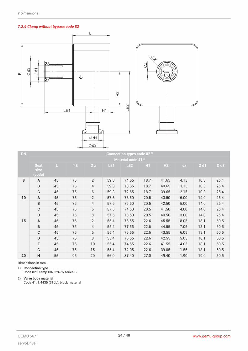
7.2.9 Clamp without bypass code 82
d1
d3
E
H2
L
d1
d3
LE1 H1 LE
2
CZ
Z
DN Connection types code 82 1)
Material code 41 2)
Seatsize
(code)
L □ E Ø z LE1 LE2 H1 H2 cz Ø d1 Ø d3
8 A 45 75 2 59.3 74.65 18.7 41.65 4.15 10.3 25.4B 45 75 4 59.3 73.65 18.7 40.65 3.15 10.3 25.4C 45 75 6 59.3 72.65 18.7 39.65 2.15 10.3 25.4
10 A 45 75 2 57.5 76.50 20.5 43.50 6.00 14.0 25.4B 45 75 4 57.5 75.50 20.5 42.50 5.00 14.0 25.4C 45 75 6 57.5 74.50 20.5 41.50 4.00 14.0 25.4D 45 75 8 57.5 73.50 20.5 40.50 3.00 14.0 25.4
15 A 45 75 2 55.4 78.55 22.6 45.55 8.05 18.1 50.5B 45 75 4 55.4 77.55 22.6 44.55 7.05 18.1 50.5C 45 75 6 55.4 76.55 22.6 43.55 6.05 18.1 50.5D 45 75 8 55.4 75.55 22.6 42.55 5.05 18.1 50.5E 45 75 10 55.4 74.55 22.6 41.55 4.05 18.1 50.5G 45 75 15 55.4 72.05 22.6 39.05 1.55 18.1 50.5
20 H 55 95 20 66.0 87.40 27.0 49.40 1.90 19.0 50.5
Dimensions in mm1) Connection type
Code 82: Clamp DIN 32676 series B
2) Valve body materialCode 41: 1.4435 (316L), block material
www.gemu-group.com24 / 48GEMÜ 567
servoDrive
7 Dimensions
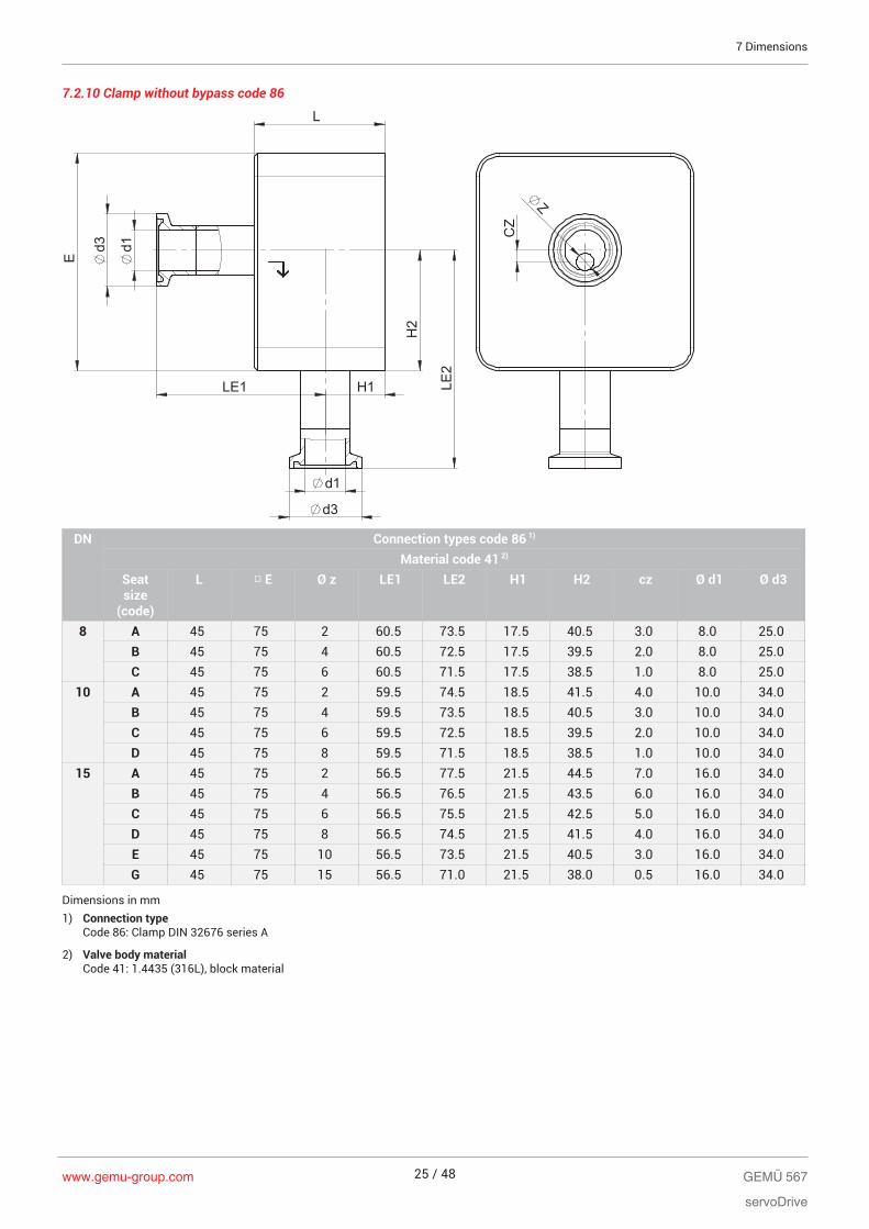
7.2.10 Clamp without bypass code 86
d1
d3
E
H2
L
d1
d3
LE1 H1 LE
2
CZ
Z
DN Connection types code 86 1)
Material code 41 2)
Seatsize
(code)
L □ E Ø z LE1 LE2 H1 H2 cz Ø d1 Ø d3
8 A 45 75 2 60.5 73.5 17.5 40.5 3.0 8.0 25.0B 45 75 4 60.5 72.5 17.5 39.5 2.0 8.0 25.0C 45 75 6 60.5 71.5 17.5 38.5 1.0 8.0 25.0
10 A 45 75 2 59.5 74.5 18.5 41.5 4.0 10.0 34.0B 45 75 4 59.5 73.5 18.5 40.5 3.0 10.0 34.0C 45 75 6 59.5 72.5 18.5 39.5 2.0 10.0 34.0D 45 75 8 59.5 71.5 18.5 38.5 1.0 10.0 34.0
15 A 45 75 2 56.5 77.5 21.5 44.5 7.0 16.0 34.0B 45 75 4 56.5 76.5 21.5 43.5 6.0 16.0 34.0C 45 75 6 56.5 75.5 21.5 42.5 5.0 16.0 34.0D 45 75 8 56.5 74.5 21.5 41.5 4.0 16.0 34.0E 45 75 10 56.5 73.5 21.5 40.5 3.0 16.0 34.0G 45 75 15 56.5 71.0 21.5 38.0 0.5 16.0 34.0
Dimensions in mm1) Connection type
Code 86: Clamp DIN 32676 series A
2) Valve body materialCode 41: 1.4435 (316L), block material
GEMÜ 567
servoDrive
www.gemu-group.com 25 / 48
7 Dimensions
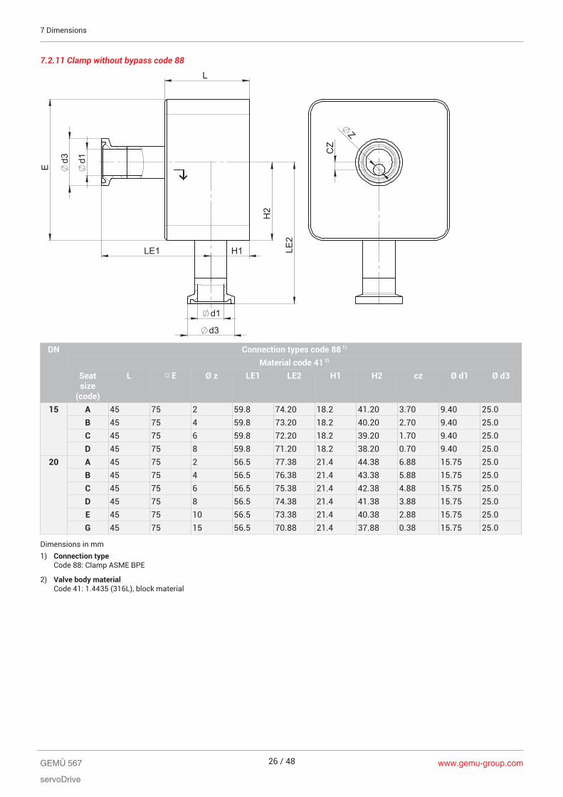
7.2.11 Clamp without bypass code 88
d1
d3
E
H2
L
d1
d3
LE1 H1 LE
2
CZ
Z
DN Connection types code 88 1)
Material code 41 2)
Seatsize
(code)
L □ E Ø z LE1 LE2 H1 H2 cz Ø d1 Ø d3
15 A 45 75 2 59.8 74.20 18.2 41.20 3.70 9.40 25.0B 45 75 4 59.8 73.20 18.2 40.20 2.70 9.40 25.0C 45 75 6 59.8 72.20 18.2 39.20 1.70 9.40 25.0D 45 75 8 59.8 71.20 18.2 38.20 0.70 9.40 25.0
20 A 45 75 2 56.5 77.38 21.4 44.38 6.88 15.75 25.0B 45 75 4 56.5 76.38 21.4 43.38 5.88 15.75 25.0C 45 75 6 56.5 75.38 21.4 42.38 4.88 15.75 25.0D 45 75 8 56.5 74.38 21.4 41.38 3.88 15.75 25.0E 45 75 10 56.5 73.38 21.4 40.38 2.88 15.75 25.0G 45 75 15 56.5 70.88 21.4 37.88 0.38 15.75 25.0
Dimensions in mm1) Connection type
Code 88: Clamp ASME BPE
2) Valve body materialCode 41: 1.4435 (316L), block material
www.gemu-group.com26 / 48GEMÜ 567
servoDrive
7 Dimensions

7.2.12 Clamp with bypass code 82
L
E
LE
H2
H1
d1 d3
d3
d1
LE
2
CZ
Z
DN Connection types code 82 1)
Material code 41 2)
Seatsize
(code)
L □ E Ø z LE1 LE2 H1 H2 cz Ø d1 Ø d3
8 A 53 75 2 67.3 74.65 18.7 41.65 4.15 10.3 25.4B 53 75 4 67.3 73.65 18.7 40.65 3.15 10.3 25.4C 53 75 6 67.3 72.65 18.7 39.65 2.15 10.3 25.4
10 A 53 75 2 65.5 76.50 20.5 43.50 6.00 14.0 25.4B 53 75 4 65.5 75.50 20.5 42.50 5.00 14.0 25.4C 53 75 6 65.5 74.50 20.5 41.5 4.00 14.0 25.4D 53 75 8 65.5 73.50 20.5 40.5 3.00 14.0 25.4
15 A 53 75 2 63.4 78.55 22.6 45.55 8.05 18.1 50.5B 53 75 4 63.4 77.55 22.6 44.55 7.05 18.1 50.5C 53 75 6 63.4 76.55 22.6 43.55 6.05 18.1 50.5D 53 75 8 63.4 75.55 22.6 42.55 5.05 18.1 50.5E 53 75 10 63.4 74.55 22.6 41.55 4.05 18.1 50.5G 53 75 15 63.4 72.05 22.6 39.05 1.55 18.1 50.5
Dimensions in mm1) Connection type
Code 82: Clamp DIN 32676 series B
2) Valve body materialCode 41: 1.4435 (316L), block material
GEMÜ 567
servoDrive
www.gemu-group.com 27 / 48
7 Dimensions

7.2.13 Clamp with bypass code 86
L
E
LE
H2
H1
d1 d3
d3
d1
LE
2
CZ
Z
DN Connection types code 86 1)
Material code 41 2)
Seatsize
(code)
L □ E Ø z LE1 LE2 H1 H2 cz Ø d1 Ø d3
8 A 53 75 2 68.5 73.5 17.5 40.5 3.0 8 25B 53 75 4 68.5 72.5 17.5 39.5 2.0 8 25C 53 75 6 68.5 71.5 17.5 38.5 1.0 8 25
10 A 53 75 2 67.5 74.5 18.5 41.5 4.0 10 34B 53 75 4 67.5 73.5 18.5 40.5 3.0 10 34C 53 75 6 67.5 72.5 18.5 39.5 2.0 10 34D 53 75 8 67.5 71.5 18.5 38.5 1.0 10 34
15 A 53 75 2 64.5 77.5 21.5 44.5 7.0 16 34B 53 75 4 64.5 76.5 21.5 43.5 6.0 16 34C 53 75 6 64.5 75.5 21.5 42.5 5.0 16 34D 53 75 8 64.5 74.5 21.5 41.5 4.0 16 34E 53 75 10 64.5 73.5 21.5 40.5 3.0 16 34G 53 75 15 64.5 71.0 21.5 38.0 0.5 16 34
Dimensions in mm1) Connection type
Code 86: Clamp DIN 32676 series A
2) Valve body materialCode 41: 1.4435 (316L), block material
www.gemu-group.com28 / 48GEMÜ 567
servoDrive
7 Dimensions
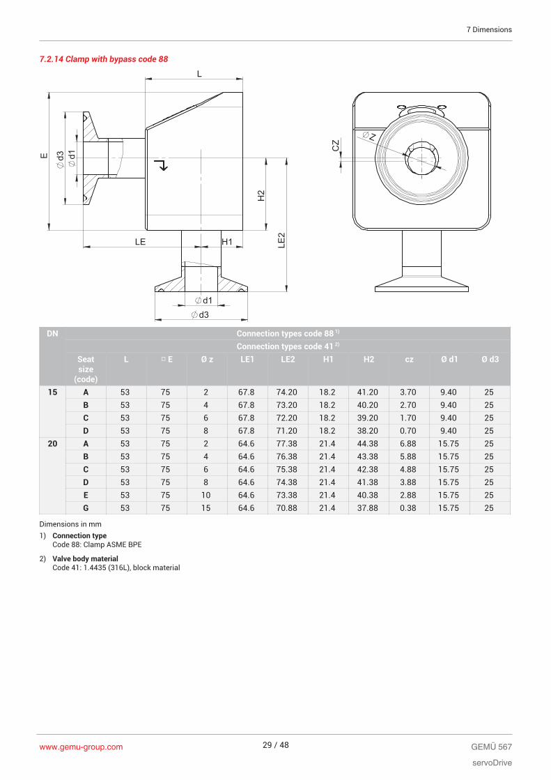
7.2.14 Clamp with bypass code 88
L
E
LE
H2
H1
d1 d3
d3
d1
LE
2
CZ
Z
DN Connection types code 88 1)
Connection types code 41 2)
Seatsize
(code)
L □ E Ø z LE1 LE2 H1 H2 cz Ø d1 Ø d3
15 A 53 75 2 67.8 74.20 18.2 41.20 3.70 9.40 25B 53 75 4 67.8 73.20 18.2 40.20 2.70 9.40 25C 53 75 6 67.8 72.20 18.2 39.20 1.70 9.40 25D 53 75 8 67.8 71.20 18.2 38.20 0.70 9.40 25
20 A 53 75 2 64.6 77.38 21.4 44.38 6.88 15.75 25B 53 75 4 64.6 76.38 21.4 43.38 5.88 15.75 25C 53 75 6 64.6 75.38 21.4 42.38 4.88 15.75 25D 53 75 8 64.6 74.38 21.4 41.38 3.88 15.75 25E 53 75 10 64.6 73.38 21.4 40.38 2.88 15.75 25G 53 75 15 64.6 70.88 21.4 37.88 0.38 15.75 25
Dimensions in mm1) Connection type
Code 88: Clamp ASME BPE
2) Valve body materialCode 41: 1.4435 (316L), block material
GEMÜ 567
servoDrive
www.gemu-group.com 29 / 48
7 Dimensions
www.gemu-group.com30 / 48GEMÜ 567
servoDrive
8 Manufacturer's information
8 Manufacturer's informationThe controller required for valve operation is not included inthe scope of delivery.
8.1 Delivery
● Check that all parts are present and check for any dam-age immediately upon receipt.
The product's performance is tested at the factory. Thescope of delivery is apparent from the dispatch documentsand the design from the order number.
8.2 Packaging
The product is packed in a cardboard box which can be re-cycled as paper.
8.3 Transport
1. Only transport the product by suitable means. Do notdrop. Handle carefully.
2. After the installation dispose of transport packing mater-ial according to relevant local or national disposal regula-tions / environmental protection laws.
8.4 Storage
1. Store the product free from dust and moisture in its ori-ginal packaging.
2. Avoid UV rays and direct sunlight.3. Do not exceed the maximum storage temperature (see
chapter "Technical data").4. Do not store solvents, chemicals, acids, fuels or similar
fluids in the same room as GEMÜ products and theirspare parts.
9 Installation in piping
9.1 Installation location
CAUTION● Do not apply external force to the valve.● Choose the installation location so that the valve cannot
be used as a foothold.● Lay the pipeline so that the valve body is protected
against transverse and bending forces, and also vibra-tions and tension.
● Only install the valve between matching aligned pipes.
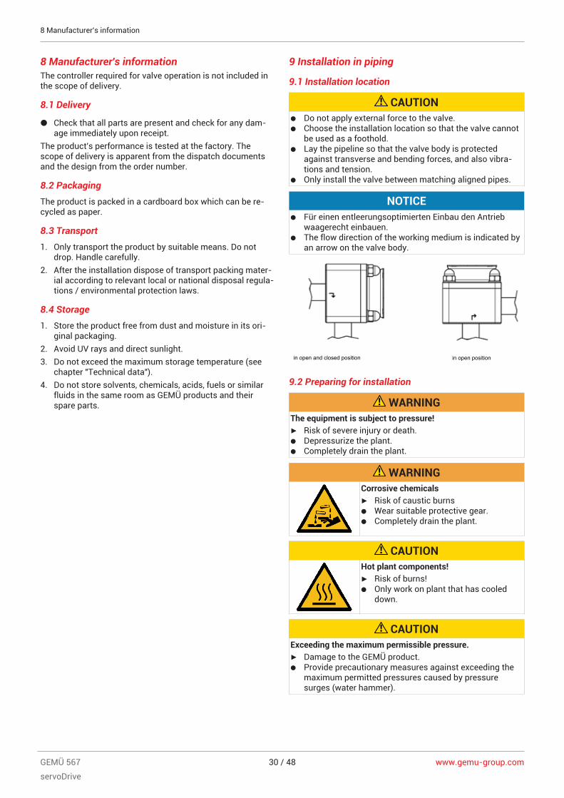
NOTICE● Für einen entleerungsoptimierten Einbau den Antrieb
waagerecht einbauen.● The flow direction of the working medium is indicated by
an arrow on the valve body.
in open and closed position in open position
9.2 Preparing for installation
WARNINGThe equipment is subject to pressure!▶ Risk of severe injury or death.● Depressurize the plant.● Completely drain the plant.
WARNINGCorrosive chemicals▶ Risk of caustic burns● Wear suitable protective gear.● Completely drain the plant.
CAUTIONHot plant components!▶ Risk of burns!● Only work on plant that has cooled
down.
CAUTIONExceeding the maximum permissible pressure.▶ Damage to the GEMÜ product.● Provide precautionary measures against exceeding the
maximum permitted pressures caused by pressuresurges (water hammer).
www.gemu-group.com 31 / 48 GEMÜ 567
servoDrive
CAUTIONUse as step.▶ Damage to the product.▶ Risk of slipping-off.● Choose the installation location so that the product can-
not be used as a foothold.● Do not use the product as a step or a foothold.
NOTICESuitability of the product!▶ The product must be appropriate for the piping system
operating conditions (medium, medium concentration,temperature and pressure) and the prevailing ambientconditions.
NOTICETools▶ The tools required for installation and assembly are not
included in the scope of delivery.● Use appropriate, functional and safe tools.
1. Ensure the product is suitable for the relevant application.2. Check the technical data of the product and the materials.3. Keep appropriate tools ready.4. Wear appropriate protective gear, as specified in the plant
operator's guidelines.5. Observe appropriate regulations for connections.6. Have installation work carried out by trained personnel.7. Shut off plant or plant component.8. Secure plant or plant component against recommission-
ing.9. Depressurize the plant or plant component.10. Completely drain the plant (or plant component) and let it
cool down until the temperature is below the media va-porization temperature and cannot cause scalding.
11. Correctly decontaminate, rinse and ventilate the plant orplant component.
12. Lay piping so that the product is protected against trans-verse and bending forces, and also from vibrations andtension.
13. Only install the product between matching aligned pipes(see chapters below).
14. Please note the flow direction (see chapter "Flow direc-tion").
15. Please note the installation position (see chapter "Install-ation position").
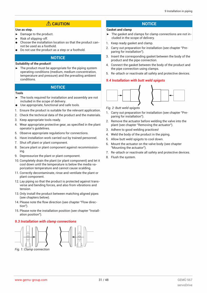
9.3 Installation with clamp connections
Fig. 1: Clamp connection
NOTICEGasket and clamp▶ The gasket and clamps for clamp connections are not in-
cluded in the scope of delivery.
1. Keep ready gasket and clamp.2. Carry out preparation for installation (see chapter "Pre-
paring for installation").3. Insert the corresponding gasket between the body of the
product and the pipe connection.4. Connect the gasket between the body of the product and
the pipe connection using clamps.5. Re-attach or reactivate all safety and protective devices.
9.4 Installation with butt weld spigots
Fig. 2: Butt weld spigots1. Carry out preparation for installation (see chapter "Pre-
paring for installation").2. Remove the actuator before welding the valve into the
plant (see chapter "Removing the actuator").3. Adhere to good welding practices!4. Weld the body of the product in the piping.5. Allow butt weld spigots to cool down.6. Mount the actuator on the valve body (see chapter
"Mounting the actuator").7. Re-attach or reactivate all safety and protective devices.8. Flush the system.
9 Installation in piping

www.gemu-group.com32 / 48GEMÜ 567
servoDrive
10 Mounting
10 MountingMounting the actuator on the distance piece:
A
18
17
16 16
18
17
11
1. Move the actuator A to the open position.2. Place actuator A on distance piece 11.3. Place washers 17 and cap nuts 18 on stud bolts 16 and
position by hand.4. Tighten cap nuts 18 diagonally (tightening torque: 16–
20 Nm).
Mounting the actuator and the distance piece:
A
1817
16
1
16
181711
5. Place actuator A and distance piece 11 on valve body 1.6. Place washers 17 and cap nuts 18 on stud bolts 16 and
position by hand.7. Tighten cap nuts 18 diagonally (tightening torque: 16–
20 Nm).

www.gemu-group.com 33 / 48 GEMÜ 567
servoDrive
10.1 Mounting for option with a bypass valve
10.1.1 Mounting the diaphragm
NOTICE▶ Important: Mount the correct diaphragm that suits the
valve (suitable for medium, medium concentration, tem-perature and pressure). The diaphragm is a wearing part.Check the technical condition and function of the dia-phragm valve before commissioning and during thewhole term of use. Carry out checks regularly and de-termine the check intervals in accordance with the con-ditions of use and/or the regulatory codes and provi-sions applicable for this application.
NOTICE▶ Important: Incorrectly mounted diaphragm may cause
valve leakage / emission of medium. In this case removethe diaphragm, check the complete valve and diaphragmand reassemble again proceeding as described above.
Diaphragm size 8:Compressor and actuator flange seen from below:
Push-fit diaphragm:
1
2
2
Item Name1 Recess of compressor2 Diaphragm tab3 Fastening spigot
1. Move the actuator to the closed position.2. Place the diaphragm with the fastening spigot in an in-
clined position at the recess of the compressor and pushit in.
NOTICE▶ Important: Do not use greases or lubricants!
3. Align diaphragm tab with identifying manufacturer andmaterial in parallel to compressor weir.
10.1.2 Mounting the actuator
1. Move the actuator to the open position.2. Position the actuator with the mounted diaphragm on the
valve body.
ð Take care to align the compressor weir and valve bodyweir (diaphragm size 8).
3. Tighten the fastening elements by hand.4. Move the actuator to the closed position.5. Fully tighten the bolts with nuts diagonally
6. Ensure that the diaphragm is compressed evenly (approx.10-15 %, visible by an even bulge to the outside).
7. Check tightness of completely assembled valve.
NOTICE▶ Important: Diaphragms set in the course of time. After
valve disassembly / assembly check that the bolts andnuts on the body are tight and retighten if necessary (atthe very latest after the first sterilisation process).
10 Mounting
www.gemu-group.com34 / 48GEMÜ 567
servoDrive
11 Electrical connection
11 Electrical connection
11.1 Electrical connection - servoDrive
Establish the electrical connection as described in the con-troller manufacturer's information.
12 Commissioningü The product is installed in piping.
ü The product is connected electrically and the control unitconfigured accordingly.
1. Check the leak-tightness and the functioning of theproduct (close the product and open it again).
2. Flush the piping system of new plant and following repairwork (the product must be fully open).
ð Harmful foreign matter has been removed.
ð The product is ready for use.3. Commission the product.

13 Error clearance
Error Error cause Error clearanceWorking medium escapes from leakdetection hole
Plug diaphragm faulty Check plug diaphragm for potentialdamage, replace plug diaphragm ifnecessary
The product doesn't open or doesn'topen fully
Actuator faulty Replace actuator cartridge, replaceactuator if necessary
Plug diaphragm incorrectly mounted Remove actuator, check plug diaphragmmounting, replace plug diaphragm ifnecessary
The product leaks downstream (doesn'tclose or doesn't close fully)
Operating pressure too high Operate the product with operatingpressure specified in datasheet
Plug diaphragm incorrectly mounted Remove actuator, check plug diaphragmmounting, correct if necessary
Foreign matter between plug diaphragmand valve seat
Remove actuator, remove foreign matter,check plug diaphragm and valve body fordamage and replace if necessary
Valve body leaks or is damaged Check valve body for potential damage,replace valve body if necessary
Plug diaphragm faulty Check plug diaphragm for potentialdamage, replace plug diaphragm ifnecessary
The product leaks between actuator andvalve body
Plug diaphragm incorrectly mounted Remove actuator, check plug diaphragmmounting, correct if necessary
Bolting between valve body and actuatorloose
Retighten bolting between valve bodyand actuator
Plug diaphragm faulty Check plug diaphragm for potentialdamage, replace plug diaphragm ifnecessary
Actuator/valve body damaged Replace actuator/valve bodyValve body connection to piping leaks Incorrect installation Check installation of valve body in piping
Sealing material faulty Replace sealing materialValve body leaks Valve body leaks or is corroded Check valve body for damage, replace
valve body if necessaryValve doesn't open/close or doesn'topen/close fully
Voltage is not connected Connect voltageCable ends incorrectly wired Wire cable ends correctly
13 Error clearance
www.gemu-group.com 35 / 48 GEMÜ 567
servoDrive
www.gemu-group.com36 / 48GEMÜ 567
servoDrive
14 Inspection/maintenance
14 Inspection/maintenance
NOTICEExceptional maintenance work!▶ Damage to the GEMÜ product.● Any maintenance work and repairs not described in
these operating instructions must not be performedwithout consulting the manufacturer first.
The operator must carry out regular visual examination of theGEMÜ products depending on the operating conditions andthe potential danger in order to prevent leakage and damage.The product also must be disassembled and checked forwear in the corresponding intervals.1. Have servicing and maintenance work performed by
trained personnel.2. Wear appropriate protective gear as specified in plant op-
erator's guidelines.3. Shut off plant or plant component.4. Secure plant or plant component against recommission-
ing.5. Depressurize the plant or plant component.6. Actuate GEMÜ products which are always in the same
position four times a year.
14.1 Replacing the actuator
14.1.1 Remove the actuator from the distance piece.
CAUTIONDanger - high voltage!▶ Electric shock.● Before performing any work on the
GEMÜ product switch off power andprotect circuit from being switched onagain.
WARNINGThe equipment is subject to pressure!▶ Risk of severe injury or death.● Depressurize the plant.● Completely drain the plant.
CAUTIONHot plant components!▶ Risk of burns!● Only work on plant that has cooled
down.
WARNINGCorrosive chemicals▶ Risk of caustic burns● Wear suitable protective gear.● Completely drain the plant.
CAUTIONUse of incorrect spare parts!▶ Damage to the GEMÜ product.▶ Manufacturer liability and guarantee will be void.● Use only genuine parts from GEMÜ.
NOTICEImportant:▶ After disassembly, clean all parts of contamination. Take
care not to damage the parts in the process. Afterwards,check parts for potential damage. If parts are damaged,replace them.
CAUTIONValve is no longer functioning correctly▶ Damaged parts are reused.● Remove and clean all parts, check for damage and re-
place if necessary.
NOTICE▶ The piping need not be drained when replacing the actu-
ator, as the valve spindle is sealed by the plug dia-phragm.
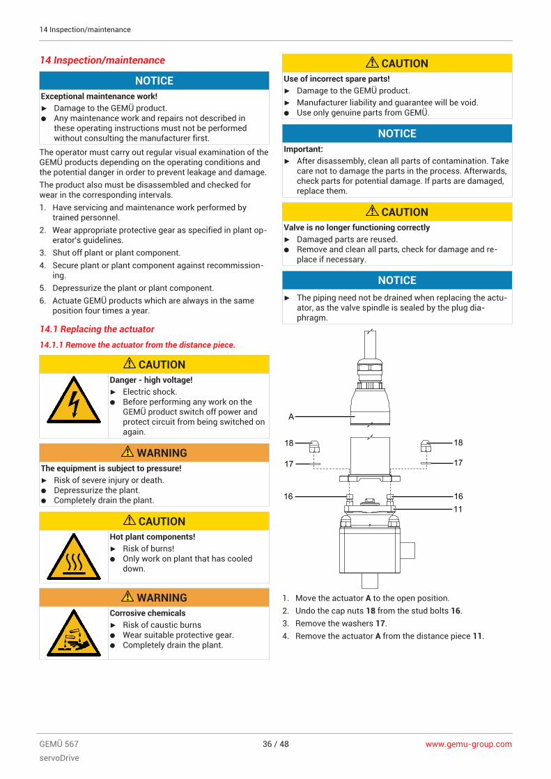
A
18
17
16 16
18
17
11
1. Move the actuator A to the open position.2. Undo the cap nuts 18 from the stud bolts 16.3. Remove the washers 17.4. Remove the actuator A from the distance piece 11.

www.gemu-group.com 37 / 48 GEMÜ 567
servoDrive
14.1.2 Mounting the actuator on the distance piece
1. Move the actuator A to the open position.2. Place actuator A on distance piece 11.3. Place washers 17 and cap nuts 18 on stud bolts 16 and
position by hand.4. Tighten cap nuts 18 diagonally (tightening torque: 16–
20 Nm).
14.1.3 Removing the actuator with the distance piece
CAUTIONDanger - high voltage!▶ Electric shock.● Before performing any work on the
GEMÜ product switch off power andprotect circuit from being switched onagain.
WARNINGThe equipment is subject to pressure!▶ Risk of severe injury or death.● Depressurize the plant.● Completely drain the plant.
CAUTIONHot plant components!▶ Risk of burns!● Only work on plant that has cooled
down.
WARNINGCorrosive chemicals▶ Risk of caustic burns● Wear suitable protective gear.● Completely drain the plant.
CAUTIONUse of incorrect spare parts!▶ Damage to the GEMÜ product.▶ Manufacturer liability and guarantee will be void.● Use only genuine parts from GEMÜ.
CAUTIONValve is no longer functioning correctly▶ Damaged parts are reused.● Remove and clean all parts, check for damage and re-
place if necessary.
A
1817
16
1
16
181711
1. Undo the cap nuts 18 from the stud bolts 16.2. Remove the washers 17.3. Remove the actuator A, including the distance piece 11,
from the valve body 1.
ð Do not damage the sealing surface!
14.1.4 Mounting the actuator with the distance piece
1. Place actuator A and distance piece 11 on valve body 1.2. Place washers 17 and cap nuts 18 on stud bolts 16 and
position by hand.3. Tighten cap nuts 18 diagonally (tightening torque: 16–
20 Nm).
14 Inspection/maintenance
www.gemu-group.com38 / 48GEMÜ 567
servoDrive
14 Inspection/maintenance
14.2 Replacing the regulating cone
14.2.1 Removing the regulating cone
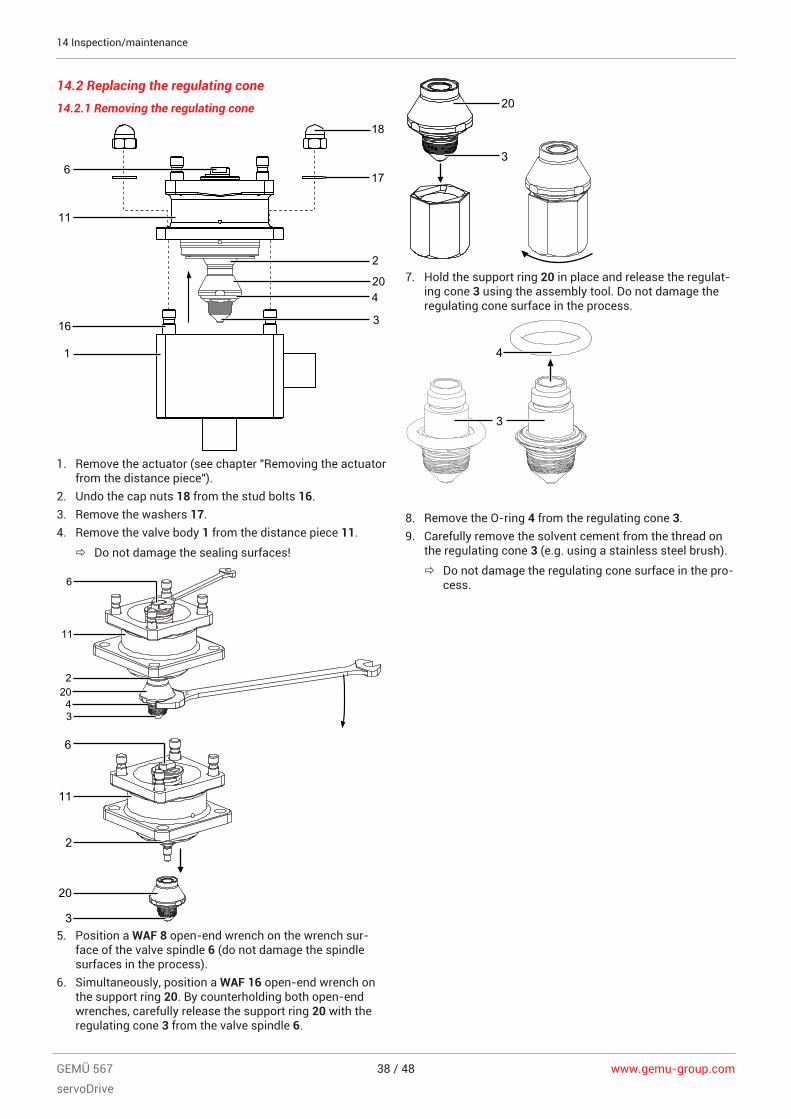
6
11
16
1
3
420
2
17
18
1. Remove the actuator (see chapter "Removing the actuatorfrom the distance piece").
2. Undo the cap nuts 18 from the stud bolts 16.3. Remove the washers 17.4. Remove the valve body 1 from the distance piece 11.
ð Do not damage the sealing surfaces!
8
16
6
11
22043
6
11
2
20
35. Position a WAF 8 open-end wrench on the wrench sur-
face of the valve spindle 6 (do not damage the spindlesurfaces in the process).
6. Simultaneously, position a WAF 16 open-end wrench onthe support ring 20. By counterholding both open-endwrenches, carefully release the support ring 20 with theregulating cone 3 from the valve spindle 6.
20
3
7. Hold the support ring 20 in place and release the regulat-ing cone 3 using the assembly tool. Do not damage theregulating cone surface in the process.
4
3
8. Remove the O-ring 4 from the regulating cone 3.9. Carefully remove the solvent cement from the thread on
the regulating cone 3 (e.g. using a stainless steel brush).
ð Do not damage the regulating cone surface in the pro-cess.
www.gemu-group.com 39 / 48 GEMÜ 567
servoDrive
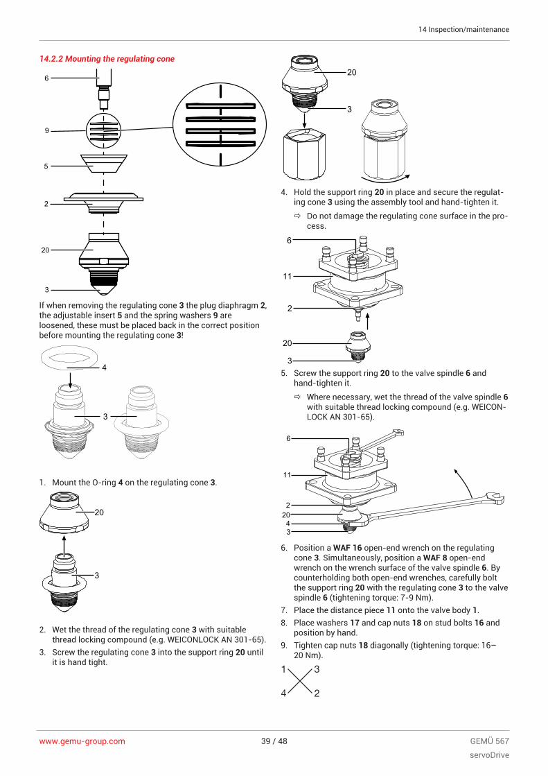
14.2.2 Mounting the regulating cone
20
6
9
5
2
3
If when removing the regulating cone 3 the plug diaphragm 2,the adjustable insert 5 and the spring washers 9 areloosened, these must be placed back in the correct positionbefore mounting the regulating cone 3!
4
3
1. Mount the O-ring 4 on the regulating cone 3.
20
3
2. Wet the thread of the regulating cone 3 with suitablethread locking compound (e.g. WEICONLOCK AN 301-65).
3. Screw the regulating cone 3 into the support ring 20 untilit is hand tight.
20
3
4. Hold the support ring 20 in place and secure the regulat-ing cone 3 using the assembly tool and hand-tighten it.
ð Do not damage the regulating cone surface in the pro-cess.
6
11
2
20
35. Screw the support ring 20 to the valve spindle 6 and
hand-tighten it.
ð Where necessary, wet the thread of the valve spindle 6with suitable thread locking compound (e.g. WEICON-LOCK AN 301-65).
8
16
6
11
22043
6. Position a WAF 16 open-end wrench on the regulatingcone 3. Simultaneously, position a WAF 8 open-endwrench on the wrench surface of the valve spindle 6. Bycounterholding both open-end wrenches, carefully boltthe support ring 20 with the regulating cone 3 to the valvespindle 6 (tightening torque: 7-9 Nm).
7. Place the distance piece 11 onto the valve body 1.8. Place washers 17 and cap nuts 18 on stud bolts 16 and
position by hand.9. Tighten cap nuts 18 diagonally (tightening torque: 16–
20 Nm).
14 Inspection/maintenance
www.gemu-group.com40 / 48GEMÜ 567
servoDrive
14 Inspection/maintenance
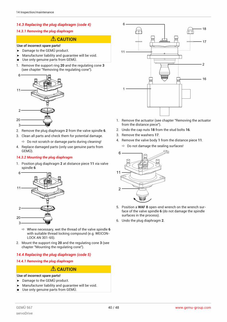
14.3 Replacing the plug diaphragm (code 4)
14.3.1 Removing the plug diaphragm
CAUTIONUse of incorrect spare parts!▶ Damage to the GEMÜ product.▶ Manufacturer liability and guarantee will be void.● Use only genuine parts from GEMÜ.
1. Remove the support ring 20 and the regulating cone 3(see chapter "Removing the regulating cone").
6
11
2
203
2. Remove the plug diaphragm 2 from the valve spindle 6.3. Clean all parts and check them for potential damage.
ð Do not scratch or damage parts during cleaning!4. Replace damaged parts (only use genuine parts from
GEMÜ).
14.3.2 Mounting the plug diaphragm
1. Position plug diaphragm 2 at distance piece 11 via valvespindle 6
6
11
2
203
ð Where necessary, wet the thread of the valve spindle 6with suitable thread locking compound (e.g. WEICON-LOCK AN 301-65).
2. Mount the support ring 20 and the regulating cone 3 (seechapter "Mounting the regulating cone").
14.4 Replacing the plug diaphragm (code 5)
14.4.1 Removing the plug diaphragm
CAUTIONUse of incorrect spare parts!▶ Damage to the GEMÜ product.▶ Manufacturer liability and guarantee will be void.● Use only genuine parts from GEMÜ.
618
17
2
16
1
11
1. Remove the actuator (see chapter "Removing the actuatorfrom the distance piece").
2. Undo the cap nuts 18 from the stud bolts 16.3. Remove the washers 17.4. Remove the valve body 1 from the distance piece 11.
ð Do not damage the sealing surfaces!8
6
11
2
5. Position a WAF 8 open-end wrench on the wrench sur-face of the valve spindle 6 (do not damage the spindlesurfaces in the process).
6. Undo the plug diaphragm 2.

www.gemu-group.com 41 / 48 GEMÜ 567
servoDrive
14.4.2 Mounting the plug diaphragm
8
6
11
2
1. Screw the plug diaphragm 2 to the valve spindle 6 andhand-tighten it.
2. Place the distance piece 11 onto the valve body 1.3. Place washers 17 and cap nuts 18 on stud bolts 16 and
position by hand.4. Tighten cap nuts 18 diagonally (tightening torque: 16–
20 Nm).
14.5 Replacing the bypass valve actuator
14.5.1 Removing the actuator
1. Move the actuator to the open position.2. Loosen fastening elements between the valve body and
the actuator diagonally and remove them.
3. Remove the actuator from the valve body.4. Move the actuator to the closed position.
NOTICEImportant:▶ After disassembly, clean all parts of contamination. Take
care not to damage the parts in the process. Afterwards,check parts for potential damage. If parts are damaged,replace them.
14.5.2 Removing the diaphragm
NOTICE▶ Before removing the diaphragm, remove the actuator,
see previous chapter "Removing the actuator").
1. Pull out the diaphragm (diaphragm size 8).
NOTICEImportant:▶ After disassembly, clean all parts of contamination. Take
care not to damage the parts in the process. Afterwards,check parts for potential damage. If parts are damaged,replace them.
2. Use only genuine parts from GEMÜ.
14.5.3 Mounting the diaphragm
NOTICE▶ Important: Mount the correct diaphragm that suits the
valve (suitable for medium, medium concentration, tem-perature and pressure). The diaphragm is a wearing part.Check the technical condition and function of the dia-phragm valve before commissioning and during thewhole term of use. Carry out checks regularly and de-termine the check intervals in accordance with the con-ditions of use and/or the regulatory codes and provi-sions applicable for this application.
NOTICE▶ Important: Incorrectly mounted diaphragm may cause
valve leakage / emission of medium. In this case removethe diaphragm, check the complete valve and diaphragmand reassemble again proceeding as described above.
Diaphragm size 8:Compressor and actuator flange seen from below:
Push-fit diaphragm:
1
2
2
Item Name1 Recess of compressor2 Diaphragm tab3 Fastening spigot
1. Move the actuator to the closed position.2. Place the diaphragm with the fastening spigot in an in-
clined position at the recess of the compressor and pushit in.
NOTICE▶ Important: Do not use greases or lubricants!
3. Align diaphragm tab with identifying manufacturer andmaterial in parallel to compressor weir.
14 Inspection/maintenance

www.gemu-group.com42 / 48GEMÜ 567
servoDrive
14 Inspection/maintenance
14.5.4 Mounting the actuator
1. Move the actuator to the open position.2. Position the actuator with the mounted diaphragm on the
valve body.
ð Take care to align the compressor weir and valve bodyweir (diaphragm size 8).
3. Tighten the fastening elements by hand.4. Move the actuator to the closed position.5. Fully tighten the bolts with nuts diagonally
6. Ensure that the diaphragm is compressed evenly (approx.10-15 %, visible by an even bulge to the outside).
7. Check tightness of completely assembled valve.
NOTICE▶ Important: Diaphragms set in the course of time. After
valve disassembly / assembly check that the bolts andnuts on the body are tight and retighten if necessary (atthe very latest after the first sterilisation process).
14.6 Cleaning the product
– Clean the product with a damp cloth.– Do not clean the product with a high pressure clean-
ing device.
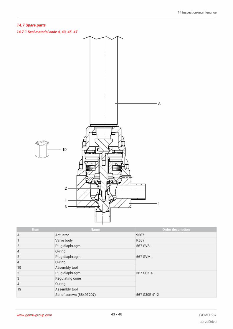
14.7 Spare parts
14.7.1 Seal material code 4, 43, 45. 47
A
2
43
1
19
Item Name Order descriptionA Actuator 95671 Valve body K5672 Plug diaphragm 567 SVS…4 O-ring2 Plug diaphragm 567 SVM...4 O-ring19 Assembly tool2 Plug diaphragm 567 SRK 4...3 Regulating cone4 O-ring19 Assembly tool
Set of screws (88491207) 567 S30E 41 2
14 Inspection/maintenance
www.gemu-group.com 43 / 48 GEMÜ 567
servoDrive

14.7.2 Seal material code 5, 55
A
2
1
Item Name Order descriptionA Actuator 95671 Valve body K5672 Plug diaphragm with regulating cone 567 SRK 5…
Set of screws (88491207) 567 S30E 41 2
14 Inspection/maintenance
www.gemu-group.com44 / 48GEMÜ 567
servoDrive
www.gemu-group.com 45 / 48 GEMÜ 567
servoDrive
15 Removal from piping1. Remove the clamp or screw connections in reverse order
to installation.2. Remove welded or solvent cemented connections using a
suitable cutting tool.3. Observe the safety information and accident prevention
regulations.
16 Disposal1. Pay attention to adhered residual material and gas diffu-
sion from penetrated media.2. Dispose of all parts in accordance with the disposal regu-
lations/environmental protection laws.
17 ReturnsLegal regulations for the protection of the environment andpersonnel require that the completed and signed return deliv-ery note is included with the dispatch documents. Returnedgoods can be processed only when this note is completed. Ifno return delivery note is included with the product, GEMÜcannot process credits or repair work but will dispose of thegoods at the operator's expense.1. Clean the product.2. Request a return delivery note from GEMÜ.3. Complete the return delivery note.4. Send the product with a completed return delivery note to
GEMÜ.
17 Returns
18 Declaration of Incorporation according to 2006/42/EC (Machinery Directive)
Declaration of Incorporationaccording to the EC Machinery Directive 2006/42/EC, Annex II, 1.B for
partly completed machinery
We, GEMÜ Gebr. Müller Apparatebau GmbH & Co. KGFritz-Müller-Straße 6-874653 Ingelfingen-Criesbach, Germany
declare that the following product
Make: GEMÜ
Commercial name: GEMÜ 567
meets the following essential requirements of the Machinery Directive 2006/42/EC:1.1.2, 1.1.3, 1.1.5, 1.3.2, 1.3.3, 1.3.4, 1.5.1, 1.5.2We also declare that the specific technical documentation has been compiled in accordance with part B of Annex VII. The manufacturer or his authorised representative undertake to transmit, in response to a reasoned request by the nationalauthorities, relevant information on the partly completed machinery. This transmission takes place:Electronically
Authorised documentation officer GEMÜ Gebr. Müller Apparatebau GmbH & Co. KGFritz-Müller-Straße 6-874653 Ingelfingen, Germany
This does not affect the industrial property rights!Important note! The partly completed machinery may be put into service only if it was determined, where appropriate, that themachinery into which the partly completed machinery is to be installed meets the provisions of this Directive.
Ingelfingen-Criesbach 29-05-2018
Joachim BrienHead of Technical Department
www.gemu-group.com46 / 48GEMÜ 567
servoDrive
18 Declaration of Incorporation according to 2006/42/EC (Machinery Directive)

19 Declaration of conformity according to 2014/30/EU (EMC Directive)
EU Declaration of Conformityaccording to 2014/30/EU (EMC Directive)
We, GEMÜ Gebr. Müller Apparatebau GmbH & Co. KGFritz-Müller-Straße 6-874653 Ingelfingen-Criesbach, Germany
declare that the product listed below complies with the safety requirements of the EMC Directive 2014/30/EU.
Description of the product: GEMÜ 567
Technical standards used:Interference resistance:– DIN EN 61326-1 (industrial processes)
Interference emission:– DIN EN 61800-3
Ingelfingen-Criesbach 29-05-2018
Joachim BrienHead of Technical Department
GEMÜ 567
servoDrive
www.gemu-group.com 47 / 48
19 Declaration of conformity according to 2014/30/EU (EMC Directive)
GEMÜ Gebr. Müller Apparatebau GmbH & Co. KGFritz-Müller-Straße 6-8, 74653 Ingelfingen-Criesbach,GermanyTel. +49 (0)7940 123-0 · [email protected]
Subject to alteration
07.2019 | 88600425
*88600425*